network management principles and practice mani subramanian 2nd edition ch14
DESCRIPTION
Network Management Principles and Practice Mani Subramanian 2nd Edition Ch14TRANSCRIPT
Part IV: Broadband Network Management > Broadband Wireless Access Networks
Objectives
Broadband wireless access networks
Multichannel multipoint distribution service, MMDS
Local multipoint distribution service, LMDS
IEEE 802.16/WiMax networks
Components of wireless access network
Base station (BS)
Subscriber station (SS)
Wireless medium
Wireless spectrum
Basic principles of wireless communication
Free-space propagation
Terrestrial propagation
Cellular mobile environment
Fading phenomena
MMDS and LMDS
Deployment in rural areas
Line-of-sight (LOS) limitation
Operational spectrum and modes
Similarity with cable access network
DOCSIS standards or proprietary protocol
DOCSIS management standards for DOCSIS-basedsystems
Network Management: Principles and Practice > Review of Information ... file:///D:/TC Engg/8th Semester/TMN/Book Network Management Princ...
1 of 4 23-Sep-15 7:41 PM

IEEE 802.16/WiMax networks
IEEE 802.16 spectrum 10–66 GHz
WiMax spectrum windows in the 2–11 GHz
WiMax mesh network eliminates LOS limitation
Management of BS and SS
Spectrum management
Service flow management
Management using wmanIfMib
Mobile wireless network
2.5, 3, and 4G technologies
TDM, TDMA, and CDMA protocol systems
Management issues
Use of mobile IP
Mobility management
Power and resource management
QoS management
Security management
VSAT network and management
We studied basics of broadband (wired) access networks and theirmanagement in the previous chapter. We will now look at the basics ofbroadband wireless access (BWA) networks and how they are managedin this chapter. Wireless access network has a lot of benefits over wiredaccess networks. It is easier to install than cable, asymmetric digitalsubscriber line (ADSL), and passive optical network (PON) networks. Itis more economical as it requires only the installation of a base station(BS). It is easily scalable in that more subscribers can be added byinstalling more BSs or more sectors in a BS. It is demographicallyadaptable for both rural and urban communities.
However, the BWA network suffers from some major disadvantages ofinadequate bandwidth for broadband, data loss, short and shallowfading, and security threat considerations. Service providers have
Network Management: Principles and Practice > Review of Information ... file:///D:/TC Engg/8th Semester/TMN/Book Network Management Princ...
2 of 4 23-Sep-15 7:41 PM

invested large capital in implementing basic wireless voice networkusing multiple and proprietary technologies. However, they have beenslow in moving to standard and interoperable technologies that couldmitigate these deficiencies. All these drawbacks are further complicatedby the lack of a common management system that can remotely andcentrally manage multiwireless technologies and multivendor products.
The application of wireless technologies can be grouped into threecategories. They are personal area networks (PANs), wireless LANs(WLANs), and access networks—metropolitan area network (MAN),GPS/general packet radio service (GPRS), and code division multipleaccess (CDMA)—and are represented in Figure 14.1.
Figure 14.1. Wireless Networks
The PAN is a short-range mobile network that covers a range in theorder of tens of feet. It is primarily used for device applications withtransmitters and receivers being mobile.
The WLAN, a good example of which is WiFi, is used primarily insidebuildings as customer premises equipment (CPE) or home network. Ithas a reach of several hundreds of meters.
The third category is broadband and narrowband access networks thatare deployed as both fixed and mobile networks. Their reach is several
Network Management: Principles and Practice > Review of Information ... file:///D:/TC Engg/8th Semester/TMN/Book Network Management Princ...
3 of 4 23-Sep-15 7:41 PM

Related Content
kilometers and is deployed outside. Examples of mobile cellularnetworks are global system for mobile communications (GSM), GPRS,and CDMA [Pahlavan and Krishnamurthy, 2002].
Fixed wireless networks, such as the MAN, are deployed as BWAnetworks in cities with antennas over the roof top of buildings. This canbe deployed as a mesh network. Point-to-multipoint BWA network isdeployed using different technologies and using different spectral bands.They are deployed in both metropolitan and rural areas. The thirdcategory is the subject of this chapter.
The ever-increasing demand of ubiquity caused by the transition fromstatic to nomadic society is driving wireless technology ahead in generaland BWA network technology in particular. We will first look at the basicprinciples of propagation for wireless transmission in Section 14.1 andunderstand the current limitations of wireless for broadbandtransmission. Fixed wireless broadband networks are addressed inSection 14.2, and the mobile wireless network is covered in Section14.3. We have included the very small aperture terminal (VSAT)network in the treatment of broadband access network in Section 14.4although it meets the requirements of broadband even less thanterrestrial wireless systems.
Network Management: Principles and Practice > Review of Information ... file:///D:/TC Engg/8th Semester/TMN/Book Network Management Princ...
4 of 4 23-Sep-15 7:41 PM
Chapter 14. Broadband Wireless Access Networks > Basic Principles
Wireless propagation for access network, fixed wireless, also known aswireless local loop (WLL), and cellular mobile wireless are discussed inthis section. There are several physical mechanisms to consider indealing with wireless propagation, which we do not have withpropagation through wired networks.
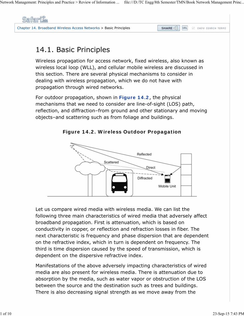
For outdoor propagation, shown in Figure 14.2, the physicalmechanisms that we need to consider are line-of-sight (LOS) path,reflection, and diffraction–from ground and other stationary and movingobjects–and scattering such as from foliage and buildings.
Figure 14.2. Wireless Outdoor Propagation
Let us compare wired media with wireless media. We can list thefollowing three main characteristics of wired media that adversely affectbroadband propagation. First is attenuation, which is based onconductivity in copper, or reflection and refraction losses in fiber. Thenext characteristic is frequency and phase dispersion that are dependenton the refractive index, which in turn is dependent on frequency. Thethird is time dispersion caused by the speed of transmission, which isdependent on the dispersive refractive index.
Manifestations of the above adversely impacting characteristics of wiredmedia are also present for wireless media. There is attenuation due toabsorption by the media, such as water vapor or obstruction of the LOSbetween the source and the destination such as trees and buildings.There is also decreasing signal strength as we move away from the
Network Management: Principles and Practice > Review of Information ... file:///D:/TC Engg/8th Semester/TMN/Book Network Management Princ...
1 of 10 23-Sep-15 7:43 PM

source antenna since open-space wave propagation is not guided but isdivergent. The major cause of frequency, phase, and time dispersioncan all be attributed to the signal from the source arriving as multiplesignals at the receiver by the multipath. They arrive at the receiver atdifferent times, with changes in frequency and phase, causinginterference of short and long duration. If it is a rapid change, itresembles phase, frequency, and time dispersion. If it is gradual and thesignal strength degrades, it is called fading. Fading can be slow or rapidtemporally or could be spatially fluctuating. Frequency shift is due toDoppler effect when the source or the receiver moves fast with respectto each other.
Let us first consider the signal strength, which varies with distance fromthe source in free space. This is shown in Figure 14.3 for an isotropicantenna.
Figure 14.3. Isotropic Antenna Propagation
The power at distance d from the source is given by
Equation 14.1
where Pr = Received power per unit area and PT = Total transmittedpower.
Figure 14.4 shows configuration of non-isotropic propagation betweenthe transmitter and the receiver antenna of finite size.
Figure 14.4. Non-Isotropic Propagation
Network Management: Principles and Practice > Review of Information ... file:///D:/TC Engg/8th Semester/TMN/Book Network Management Princ...
2 of 10 23-Sep-15 7:43 PM
For a given effective receiver antenna size, AR, and receiver efficiency,ηR, the total received power, PR, for an isotropic transmitter antenna is
Equation 14.2
Now include antenna gain, GT of transmitter for a finite antenna.Normalizing the effective antenna area AT with respect to wavelength, λ
Equation 14.3
Multiplying PT by GT in Equation (14-2) for the non-isotropic caseshown in Figure 14.4, we get
Equation 14.4
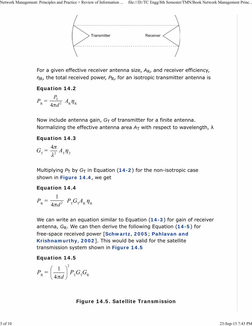
We can write an equation similar to Equation (14-3) for gain of receiverantenna, GR. We can then derive the following Equation (14-5) forfree-space received power [Schwartz, 2005; Pahlavan andKrishnamurthy, 2002]. This would be valid for the satellitetransmission system shown in Figure 14.5
Equation 14.5
Figure 14.5. Satellite Transmission
Network Management: Principles and Practice > Review of Information ... file:///D:/TC Engg/8th Semester/TMN/Book Network Management Princ...
3 of 10 23-Sep-15 7:43 PM
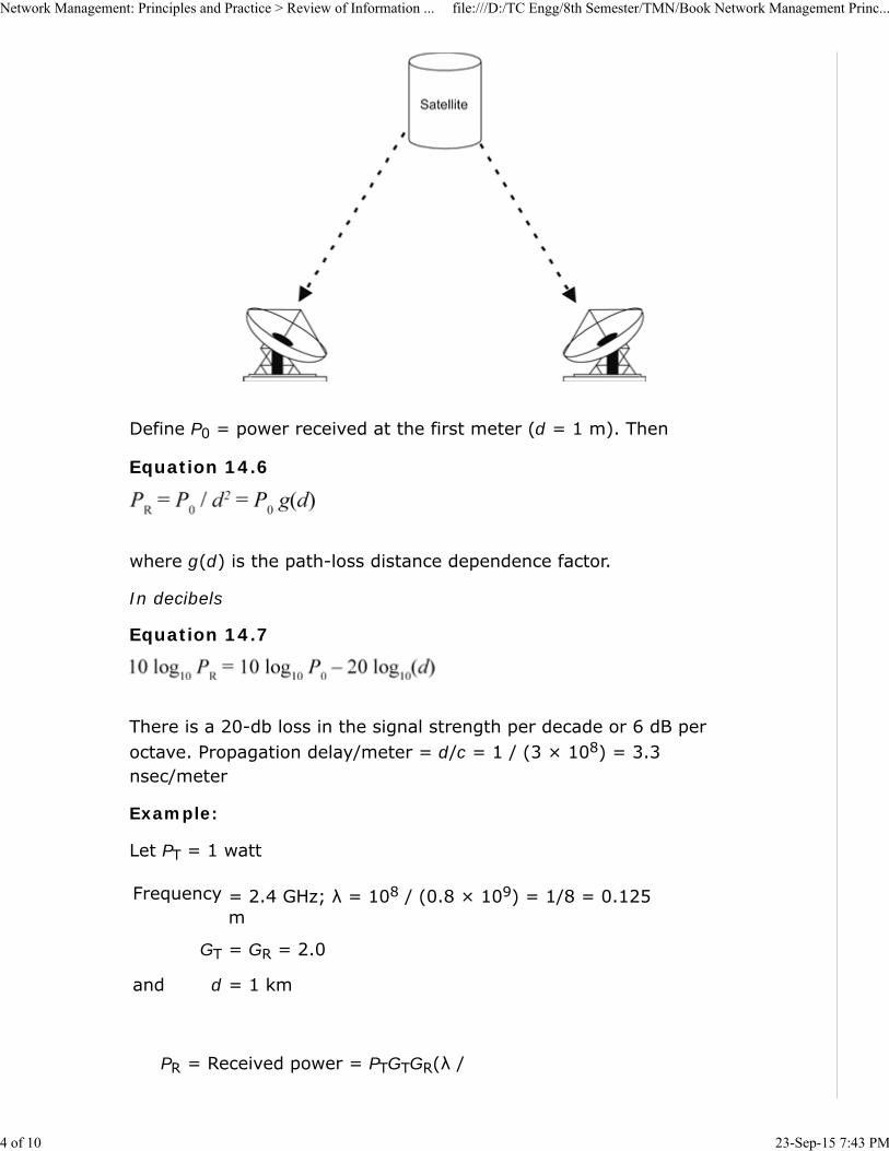
Define P0 = power received at the first meter (d = 1 m). Then
Equation 14.6
where g(d) is the path-loss distance dependence factor.
In decibels
Equation 14.7
There is a 20-db loss in the signal strength per decade or 6 dB peroctave. Propagation delay/meter = d/c = 1 / (3 × 10⁸) = 3.3nsec/meter
Example:
Let PT = 1 watt
Frequency = 2.4 GHz; λ = 108 / (0.8 × 10⁹) = 1/8 = 0.125m
GT = GR = 2.0
and d = 1 km
PR = Received power = PTGTGR(λ /
Network Management: Principles and Practice > Review of Information ... file:///D:/TC Engg/8th Semester/TMN/Book Network Management Princ...
4 of 10 23-Sep-15 7:43 PM

4π)2 (1 / d2)
= PT 4.0 (0.125 /(4 × 3.14))2 (1/d2)
or
PR = 4 × 10⁻⁴ (1 / d2) watts
= 4 × 10⁻¹⁰ watts
For d = 1 m,
P0 = 4 × 10⁻⁴ watts
= 0.4 mW
The free-space propagation model derived in Section 14.1.1 can beapplied to satellite propagation. However, it does not apply to theterrestrial propagation model. Figure 14.6 shows a simple terrestrialpropagation model. The signal travels from the transmitter to thereceiver along two paths. The first is a direct path and the other anindirect path caused by ground reflection. If the height of thetransmitter and receiver antennas is assumed to be ht and hr, it can beshown [Schwartz, 2005] that
Equation 14.8
where d is the horizontal distance between the transmitter and thereceiver.
Figure 14.6. Terrestrial Two-Ray Propagation Model
Network Management: Principles and Practice > Review of Information ... file:///D:/TC Engg/8th Semester/TMN/Book Network Management Princ...
5 of 10 23-Sep-15 7:43 PM

Comparing Equations (14-5) and (14-8), we observe that thedependency of the received signal power on distance has changed from1/d2 to 1/d4. Expressing this in decibels, Equation (14-7) now becomes
Equation 14.9
Now, the distance-dependent path-loss factor is 40 dB per decade or 12dB per octave. Figure 14.7 shows the two cases. In the real world,distance dependency would transition between the two cases as eitherthe distance is increased or the height of the antenna is varied.
Figure 14.7. Path Loss Depending on Distance
Example:
Coverage in cellular network configuration
PT = Transmitted power from the BS = 1 kW
PR = Receiver sensitivity = –100 dBm
Path loss at the first meter = 40 dB
Path-loss distance dependency g(d) = 1/d4
Network Management: Principles and Practice > Review of Information ... file:///D:/TC Engg/8th Semester/TMN/Book Network Management Princ...
6 of 10 23-Sep-15 7:43 PM
PT in dB = 10 log10 1,000/0.001 = 60 dBm
PR in dB = –100 dBm
Total path loss allowed = 60 – (–100) dB = 160 dB
P0 = 32 dB
From Equation (14-9)
10 log 10 PR = 10 log10 P0– 40 log (d)
4010 log10 (d)max = 160 – 40 = 120 dB
dmax = 10131 / 40 ≅ 103 = 1 km
Power at the receiver fluctuates due to fading phenomena, which we willsoon address. We can generalize the average power received bycombining Equations (14-6) and (14-8)
Equation 14.10
For free-space wireless
g(d) =kf/d2
kf =(λ/4π)2
For terrestrial wireless
g(d) =kt/d4
kt = (hthr)2
Various factors contributing to fading phenomena in outdoor wirelesspropagation were presented in Figure 14.2. All of them impact theinstantaneous value of the received signal that is varying temporally andspatially. The magnitude of the received power fluctuation is causedprimarily either by path loss due to absorption and scattering, or due tomultipath fading caused by the interference of direct wave withreflected, diffracted, or scattered waves.
The fading phenomenon has both spatial and temporal dependencies.We can classify them into large-scale fading and small-scale fading. The
Network Management: Principles and Practice > Review of Information ... file:///D:/TC Engg/8th Semester/TMN/Book Network Management Princ...
7 of 10 23-Sep-15 7:43 PM

former occurs at a slow spatial rate compared to the wavelength and isgenerally slow in temporal variation. The latter, namely small-scalefading, occurs at spatial dimension comparable to the wavelength andgenerally occurs at a more spatially rapid rate compared to large-scalefading. In addition to the above two classifications, there is fading dueto Doppler effect in fast-moving mobile units.
Shadow Fading. Large-scale fading, which occurs at relatively longdistances compared to wavelength, is also called shadow fading. It iscaused due to reflection, scattering, diffraction, meteorological changesuch as absorption, etc. The fading follows a log-normal (Gaussian)distribution with a standard deviation of 6–10 dB around average power,as shown in Figure 14.8.
Figure 14.8. Shadow Fading Over Average Path Loss
Cellular Configuration in a Wireless System. Wireless propagationenvironment can be classified based on the range and rangedependency of the BS. An area served by a BS is called a cell, and atotal wireless system is designed using multiple cells, each cell beingserved by a BS.
Free-space propagation described earlier, which is applicable to satellitewireless, could cover a very large area spanning hundreds of kilometersdepending on the power of the transmitter, height and distance of the
Network Management: Principles and Practice > Review of Information ... file:///D:/TC Engg/8th Semester/TMN/Book Network Management Princ...
8 of 10 23-Sep-15 7:43 PM
satellite, and the beam width of the antennae of the transmitter and thereceiver.
Terrestrial wireless propagation can be broadly split into macrocellularareas and microcellular areas.
Macrocells cover an area of a few kilometers to tens of kilometers.These are typically cellular telephony BSs operating at 900 MHz and1,800–1,900 MHz band. Small-scale fading in the macrocell isempirically found to follow Raleigh distribution.
Microcells typically cover a range of up to a kilometer and operate in thefrequency spectrum of up to 11 GHz; commercial deployments includeWiFi (2.4 GHz) and WiMax (2.1 GHz). The antennas are at low heightson roof tops and lamp poles in the urban area and hence the cell patternvaries considerably. LOS could be a serious problem in configuration andis overcome by multiple BSs connected in a mesh configuration orimplementing orthogonal frequency division multiplexing (OFDM), whichis an enabling technology in broadband communications [Schwartz,2005].
Small-Scale Fading. As we stated earlier, small-scale fading is causedby multipath fading, which is constructive or destructive interference ofsignals arriving at the receiver traversing different paths and hence atdifferent phases. Moving the receiver by a distance comparable to thewavelength, the signal strength could vary significantly. For example, forthe IEEE 802.11b WiFi signal, the data rate could go down from a strongseveral megabits per second (max. data rate is 11 Mbps) to less than 1Kbps for displacement in the order of centimeters. Even for a wirelessreceiver in a stationary state, small-scale fading could occur as theenvironment fluctuates.
Statistics of the variation of the signal due to small-scale fading dependson the cellular structure of the BSs. In the macrocellular configuration,several multipath rays (5 or 6) interfere with each other and fadingdistribution follows Raleigh statistics. In microcellular architecture, thedirect ray is much stronger than the indirect signal and statistics trendto be Ricean distribution.
Fading Mitigation Techniques. With all the technologies available,although fading could not be completely eliminated, it could bemitigated significantly. One of the techniques used is to spread digitalsignals out in time by interleaving them. This eliminates loss of adjacentbits of information, i.e., bytes or words of information, and makes iteasier to reconstruct the signal using various error correctiontechniques. This reduces fast fading and possible bursts of noise. It is
Network Management: Principles and Practice > Review of Information ... file:///D:/TC Engg/8th Semester/TMN/Book Network Management Princ...
9 of 10 23-Sep-15 7:43 PM

used in the second-, third-, and fourth- (2G, 3G, and 4G) generationcellular and WLAN systems.
Another technique is to use OFDM using Fourier analysis techniques[Forouzan, 2006; Schwartz, 2005] described in Appendix D. Thisensures that each peak or maximum of a digital signal coincides withthe valleys or zeros of the rest of the digital signals in the spectrum.This technique is used in all wireless access systems.
A third method is to use the multiple input multiple output (MIMO)technique. This method takes advantage of multipath fading. It usesmultiple antennas to transmit and receive the same signals and recoverthem using correlation techniques. Frequency, spatial, and temporaldiversity spread signal can be reconstructed and fading mitigated.
A fourth technique is to introduce equalization in receivers based on apriori knowledge of the distortion of the signal.
Network Management: Principles and Practice > Review of Information ... file:///D:/TC Engg/8th Semester/TMN/Book Network Management Princ...
10 of 10 23-Sep-15 7:43 PM
Chapter 14. Broadband Wireless Access Ne... > Fixed Broadband Wireless Access Netw...
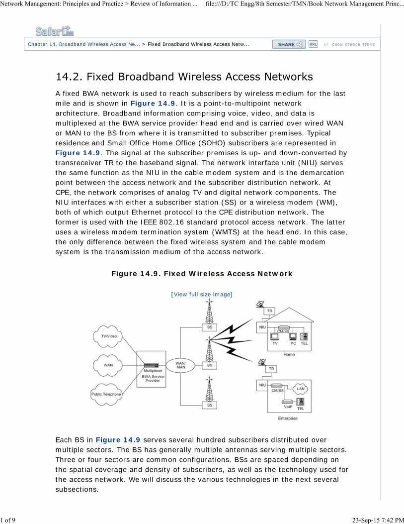
A fixed BWA network is used to reach subscribers by wireless medium for the lastmile and is shown in Figure 14.9. It is a point-to-multipoint networkarchitecture. Broadband information comprising voice, video, and data ismultiplexed at the BWA service provider head end and is carried over wired WANor MAN to the BS from where it is transmitted to subscriber premises. Typicalresidence and Small Office Home Office (SOHO) subscribers are represented inFigure 14.9. The signal at the subscriber premises is up- and down-converted bytransreceiver TR to the baseband signal. The network interface unit (NIU) servesthe same function as the NIU in the cable modem system and is the demarcationpoint between the access network and the subscriber distribution network. AtCPE, the network comprises of analog TV and digital network components. TheNIU interfaces with either a subscriber station (SS) or a wireless modem (WM),both of which output Ethernet protocol to the CPE distribution network. Theformer is used with the IEEE 802.16 standard protocol access network. The latteruses a wireless modem termination system (WMTS) at the head end. In this case,the only difference between the fixed wireless system and the cable modemsystem is the transmission medium of the access network.
Figure 14.9. Fixed Wireless Access Network
[View full size image]
Each BS in Figure 14.9 serves several hundred subscribers distributed overmultiple sectors. The BS has generally multiple antennas serving multiple sectors.Three or four sectors are common configurations. BSs are spaced depending onthe spatial coverage and density of subscribers, as well as the technology used forthe access network. We will discuss the various technologies in the next severalsubsections.
Network Management: Principles and Practice > Review of Information ... file:///D:/TC Engg/8th Semester/TMN/Book Network Management Princ...
1 of 9 23-Sep-15 7:42 PM

14.2.1. MMDS NetworkMultipoint multichannel distribution service (MMDS) is based on point-to-multipoint network architecture. It operates at 2.5–2.686 GHz and carriesdigital information in the 6-MHz analog TV channel. Well-developed cable accessnetwork standards are modified and defined as DOCSIS+ (Data-Over-CableService Interface Specifications). We can visualize the MMDS system as the cablemodem system with the HFC medium replaced by wireless.
An MMDS broadband system shown in Figure 14.10 comprises a head end,which is the BS, antennas at the head end and at the SS, transreceivers thatconvert the baseband signal to the microwave signal, and the cable modem at thesubscriber end that converts DOCSIS+ protocol to Ethernet protocol for a CPEdistribution network. The range of a BS is about 25 kilometers, and hence BSs areseparated by about 50 kilometers. The broadband signal is brought to the BSs viaWAN or MAN. The range can be extended by having repeater stations, whichenables low-powered systems to be used at the SS.
Figure 14.10. Multichannel Multipoint Distribution Service
Downstream propagation is TDM broadcast mode and upstream is TDMAtransmission. Downstream modulation is QAM and upstream is QPSK. The systemis ideal for rural areas. When it is used in the metropolitan area, the LOS is notalways good and OFDM modulation is used to mitigate the problem.
14.2.2. LMDS NetworkLocal multipoint distribution service (LMDS) is a last-mile broadband accessnetwork that operates in the K band spectrum, primarily in the 20–40 GHz band.There is no uniformity in the spectral allocation across the world. FCC hasallocated the 27.5–29.5 GHz band in the US to LMDS. The architecture of LMDS isthe same as MMDS. Its range is shorter than MMDS, about 5 kilometers and
Network Management: Principles and Practice > Review of Information ... file:///D:/TC Engg/8th Semester/TMN/Book Network Management Princ...
2 of 9 23-Sep-15 7:42 PM
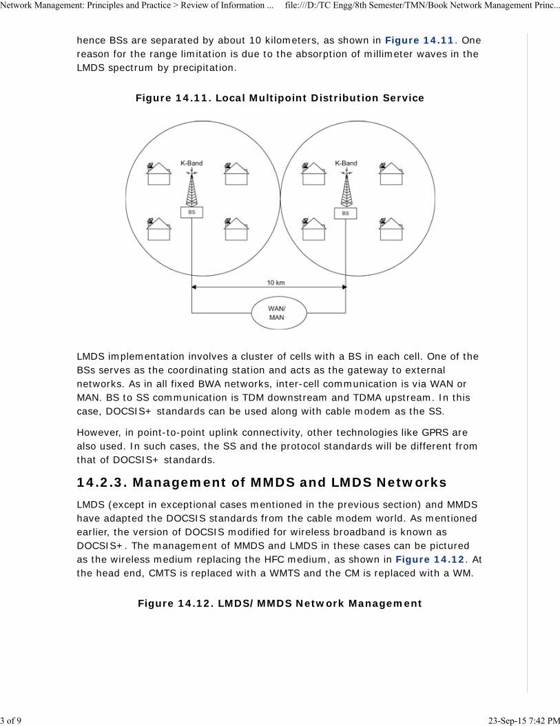
hence BSs are separated by about 10 kilometers, as shown in Figure 14.11. Onereason for the range limitation is due to the absorption of millimeter waves in theLMDS spectrum by precipitation.
Figure 14.11. Local Multipoint Distribution Service
LMDS implementation involves a cluster of cells with a BS in each cell. One of theBSs serves as the coordinating station and acts as the gateway to externalnetworks. As in all fixed BWA networks, inter-cell communication is via WAN orMAN. BS to SS communication is TDM downstream and TDMA upstream. In thiscase, DOCSIS+ standards can be used along with cable modem as the SS.
However, in point-to-point uplink connectivity, other technologies like GPRS arealso used. In such cases, the SS and the protocol standards will be different fromthat of DOCSIS+ standards.
14.2.3. Management of MMDS and LMDS NetworksLMDS (except in exceptional cases mentioned in the previous section) and MMDShave adapted the DOCSIS standards from the cable modem world. As mentionedearlier, the version of DOCSIS modified for wireless broadband is known asDOCSIS+. The management of MMDS and LMDS in these cases can be picturedas the wireless medium replacing the HFC medium, as shown in Figure 14.12. Atthe head end, CMTS is replaced with a WMTS and the CM is replaced with a WM.
Figure 14.12. LMDS/MMDS Network Management
Network Management: Principles and Practice > Review of Information ... file:///D:/TC Engg/8th Semester/TMN/Book Network Management Princ...
3 of 9 23-Sep-15 7:42 PM
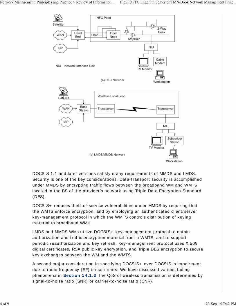
DOCSIS 1.1 and later versions satisfy many requirements of MMDS and LMDS.Security is one of the key considerations. Data-transport security is accomplishedunder MMDS by encrypting traffic flows between the broadband WM and WMTSlocated in the BS of the provider’s network using Triple Data Encryption Standard(DES).
DOCSIS+ reduces theft-of-service vulnerabilities under MMDS by requiring thatthe WMTS enforce encryption, and by employing an authenticated client/serverkey-management protocol in which the WMTS controls distribution of keyingmaterial to broadband WMs.
LMDS and MMDS WMs utilize DOCSIS+ key-management protocol to obtainauthorization and traffic encryption material from a WMTS, and to supportperiodic reauthorization and key refresh. Key-management protocol uses X.509digital certificates, RSA public key encryption, and Triple DES encryption to securekey exchanges between the WM and the WMTS.
A second major consideration in specifying DOCSIS+ over DOCSIS is impairmentdue to radio frequency (RF) impairments. We have discussed various fadingphenomena in Section 14.1.3 The QoS of wireless transmission is determined bysignal-to-noise ratio (SNR) or carrier-to-noise ratio (CNR).
Network Management: Principles and Practice > Review of Information ... file:///D:/TC Engg/8th Semester/TMN/Book Network Management Princ...
4 of 9 23-Sep-15 7:42 PM
For downstream performance, CNR in a cable downstream 6-MHz channel shouldnot be less than 35 dB, while the typical multipath (micro-reflections in the cable)should not be greater than 1.5 ms. The upstream performance of SNR in thecable should be less than 25 dB and a typical multipath of less than 1.5 ms.Contrasted with this downstream and upstream performance in wirelesspropagation, SNR is determined mainly by the transmit level, antenna gain,distance, link budget, interference noise, and the receiver-noise figure and isworse than for cable. More robustness is needed both in the downstream andupstream physical and MAC layers for BWA over cable. DOCSIS+ addresses theseby restricting the specifications of DOCSIS [Wilson and Shirali, 2008]. Some ofthese limitations are mitigated by using OFDM.
MMDS and LMDS will in the future migrate to 802.16 or WiMax standard, whichwe will consider next.
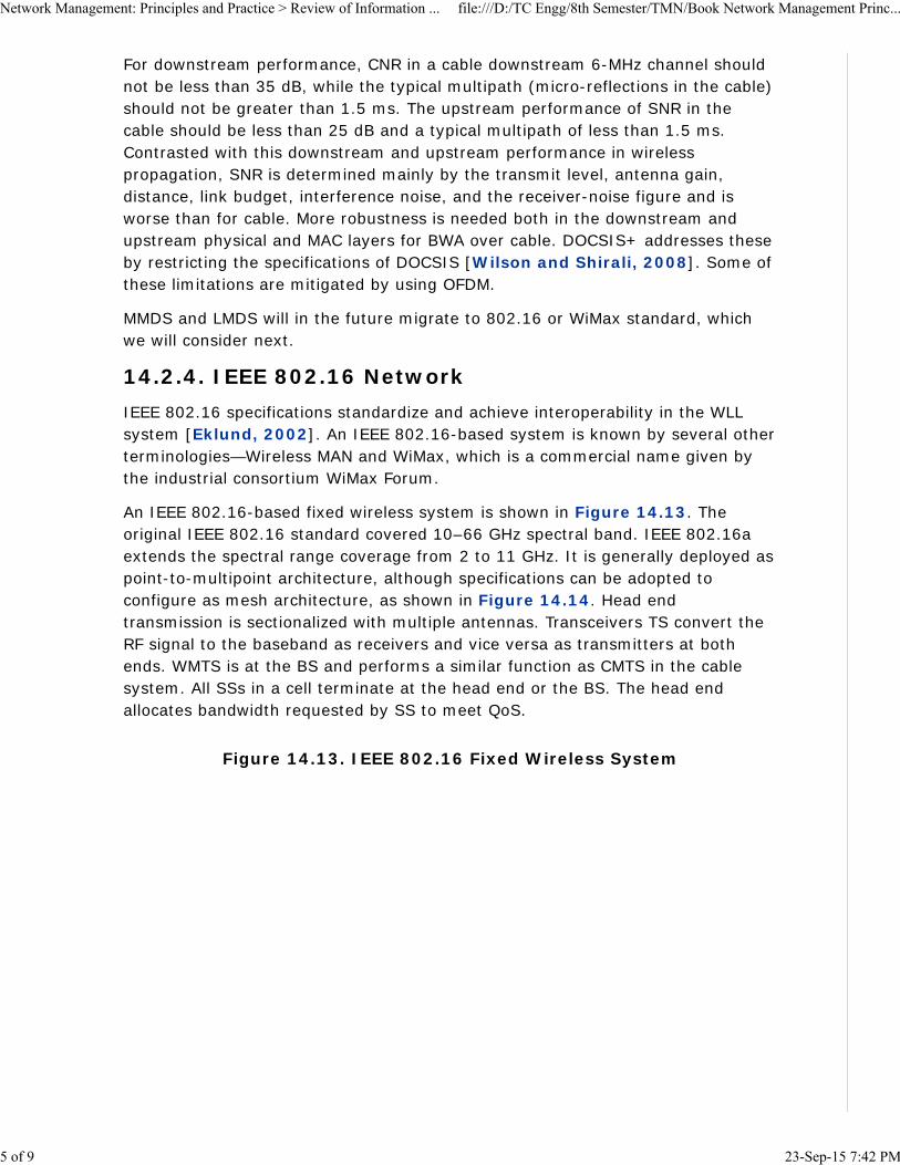
14.2.4. IEEE 802.16 NetworkIEEE 802.16 specifications standardize and achieve interoperability in the WLLsystem [Eklund, 2002]. An IEEE 802.16-based system is known by several otherterminologies—Wireless MAN and WiMax, which is a commercial name given bythe industrial consortium WiMax Forum.
An IEEE 802.16-based fixed wireless system is shown in Figure 14.13. Theoriginal IEEE 802.16 standard covered 10–66 GHz spectral band. IEEE 802.16aextends the spectral range coverage from 2 to 11 GHz. It is generally deployed aspoint-to-multipoint architecture, although specifications can be adopted toconfigure as mesh architecture, as shown in Figure 14.14. Head endtransmission is sectionalized with multiple antennas. Transceivers TS convert theRF signal to the baseband as receivers and vice versa as transmitters at bothends. WMTS is at the BS and performs a similar function as CMTS in the cablesystem. All SSs in a cell terminate at the head end or the BS. The head endallocates bandwidth requested by SS to meet QoS.
Figure 14.13. IEEE 802.16 Fixed Wireless System
Network Management: Principles and Practice > Review of Information ... file:///D:/TC Engg/8th Semester/TMN/Book Network Management Princ...
5 of 9 23-Sep-15 7:42 PM

Figure 14.14. WiMax Mesh Network
The SS performs a similar function as the cable modem but is more complex thanthe cable modem. It is designed as a highly directional antenna to minimize thetransmitter power. The downstream transmission mode is the TDM broadcastmode and the upstream is the TDMA. Upstream and downstream operate in thefrequency division duplex mode for bidirectional transmission.
14.2.5. WiMax NetworkWiMax specifications are defined by IEEE 802.16d, which is a modification of802.16a and 802.16c. Some of the limitations due to LOS requirements aremitigated by operating in a lower spectral range of 2–11 Gbps. The WiMax Forumhas allocated several frequency bands for 802.16d products, both licensed(2.5–2.69 and 3.4–3.6 GHz) and unlicensed spectra (5.725–5.850 GHz).
Multipath phenomenon is taken advantage of to partially mitigate the LOSlimitation and, in addition, OFDM technology is used at the PHY layer to improveperformance. Channel quality feedback from SS to BS is used to dynamically vary
Network Management: Principles and Practice > Review of Information ... file:///D:/TC Engg/8th Semester/TMN/Book Network Management Princ...
6 of 9 23-Sep-15 7:42 PM
the power and data rate to improve QoS. By using TDMA in the MAC layer, andhead end allocating the desired bandwidth to the SSs, the broadband requirementof prioritization of real-time over non-real-time traffic is accomplished.
In a metropolitan area, where antennas are positioned over the roof tops ofbuildings, the network is configured as mesh network, as shown in Figure 14.14.In this case, obstruction of signal between any two antennas is overcome. If adirect LOS path is not available, the system will redirect traffic throughintermediate nodes.
The IEEE 802.16e standard is an extension to the approved IEEE 802.16/16astandard. The purpose of 802.16e is to add limited mobility to the currentstandard, which is designed for a fixed operation.
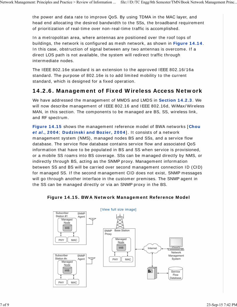
14.2.6. Management of Fixed Wireless Access NetworkWe have addressed the management of MMDS and LMDS in Section 14.2.3. Wewill now describe management of IEEE 802.16 and IEEE 802.16d, WiMax/WirelessMAN, in this section. The components to be managed are BS, SS, wireless link,and RF spectrum.
Figure 14.15 shows the management reference model of BWA networks [Chouet al., 2004; Dudzinski and Bozier, 2004]. It consists of a networkmanagement system (NMS), managed nodes BS and SSs, and a service flowdatabase. The service flow database contains service flow and associated QoSinformation that have to be populated in BS and SS when service is provisioned,or a mobile SS roams into BS coverage. SSs can be managed directly by NMS, orindirectly through BS, acting as the SNMP proxy. Management informationbetween SS and BS will be carried over second management connection ID (CID)for managed SS. If the second management CID does not exist, SNMP messageswill go through another interface in the customer premises. The SNMP agent inthe SS can be managed directly or via an SNMP proxy in the BS.
Figure 14.15. BWA Network Management Reference Model
[View full size image]
Network Management: Principles and Practice > Review of Information ... file:///D:/TC Engg/8th Semester/TMN/Book Network Management Princ...
7 of 9 23-Sep-15 7:42 PM

Figure 14.16 shows the MIB structure of wmanIfMib for 802.16 and is node 184under transmission (mib-2 10). It defines the interface table for a wireless MANinterface. Table 14.1 describes some key attributes of BS in the wmanIfMib.There are controllers associated with the BS and sectors. The SNMP agent can beimplemented in the BS controller or sector controller. There is one entry for eachBS if the SNMP agent is implemented in a common BS controller. There is onlyone entry for the BS sector if the SNMP agent is implemented in the sectorcontroller. This is shown in Table 14.1. The usage table for the SS is shown inTable 14.2.
Figure 14.16. WMAN IF MIB
Table 14.1. Usage of ifTable Objects for the Base Station
ifTable ifIndex ifType(LANA) ifSpeed ifPhysAddress ifAdminStatus ifOperStatus
BSSector 1
AnifEntryper BSsector(1)
propBWAp2MP Null MAC Address ofBS Sector
AdministrationStatus
OperationalStatus
BSSector 2
AnifEntryper BSsector(2)
propBWAp2MP Null MAC Address ofBS Sector
AdministrationStatus
OperationalStatus
BSSector 3
AnifEntryper BSsector(3)
propBWAp2MP Null MAC Address ofBS Sector
AdministrationStatus
OperationalStatus
Network Management: Principles and Practice > Review of Information ... file:///D:/TC Engg/8th Semester/TMN/Book Network Management Princ...
8 of 9 23-Sep-15 7:42 PM

ifTable ifIndex ifType(LANA) ifSpeed ifPhysAddress ifAdminStatus ifOperStatus
Ethernet Null MAC Address ofBS Sector
AdministrationStatus
OperationalStatus
Table 14.2. Usage of ifTable Objects for the Subscriber Station
ifTable ifIndex ifType(LANA)
ifSpeed ifPhysAddress
ifAdminStatus
ifOperStatus
SS AnifEntryfor SS
propBWAp2MP Null MACAddressof SS
AdministrationStatus
OperationalStatus
Ethernet Null MACAddress
AdministrationStatus
OperationalStatus
wmanIfMibObjects under wmanIfMib has three subnodes. wmanIfBsObjects (1)has the tables associated with the BS; wmanIfSsObjects (2) has the tablesassociated with the SS; and wmanIfCommonObjects (3) has the tables associatedwith the common objects.
BWA supports various classes of service with various QoS for bearer services. Itcan be configured for bandwidth negotiation for connectionless service, and withstate information, is maintainable for connection-oriented service. It supportsATM traffic categories: CBR, VBR-rt, VBR-nrt, ABR, and Internet categories forintegrated and differentiated services.
Network Management: Principles and Practice > Review of Information ... file:///D:/TC Engg/8th Semester/TMN/Book Network Management Princ...
9 of 9 23-Sep-15 7:42 PM
Chapter 14. Broadband Wireless Access Networks > Mobile Wireless Networks
Although the wired part of the topology for a cellular mobile network issimilar to fixed wireless systems, the topology and characteristics of awireless segment are very different. Even though today’s wirelesstechnology for cellular mobile systems is digital, it is essentially anextension of the voice-based analog system. The 2G technology GSM isprimarily used for voice transmission and is essentially circuit switched.The 2.5G networks are GPRS and enhanced data rates for GSMevolution (EDGE) are enhancements to GSM. Voice service uses circuitswitching and data service uses packet switching. The 2G networks areTDMA based and 2.5G networks are CDMA based. Standardization andhence interoperability is introduced in 3G networks by ITU-T and iscalled the universal mobile telecommunication system (UMTS). They arebased on CDMA protocol. An IP-based mobile network is a 4G networkand is still in its embryonic stage.
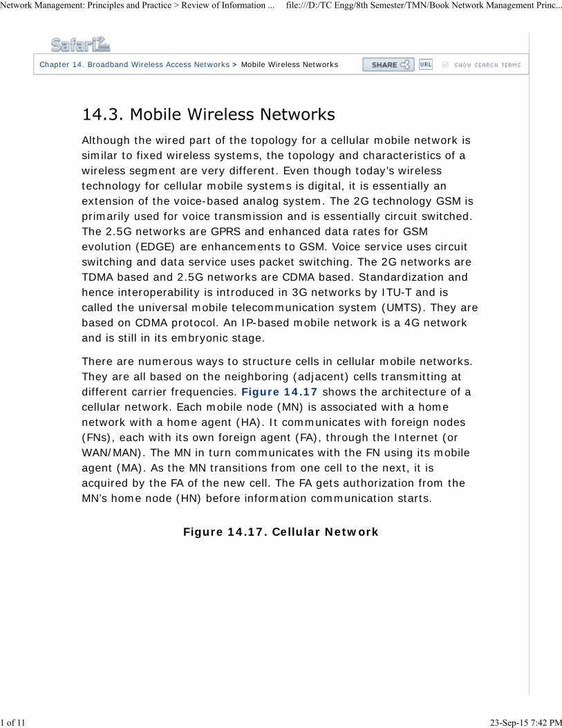
There are numerous ways to structure cells in cellular mobile networks.They are all based on the neighboring (adjacent) cells transmitting atdifferent carrier frequencies. Figure 14.17 shows the architecture of acellular network. Each mobile node (MN) is associated with a homenetwork with a home agent (HA). It communicates with foreign nodes(FNs), each with its own foreign agent (FA), through the Internet (orWAN/MAN). The MN in turn communicates with the FN using its mobileagent (MA). As the MN transitions from one cell to the next, it isacquired by the FA of the new cell. The FA gets authorization from theMN’s home node (HN) before information communication starts.
Figure 14.17. Cellular Network
Network Management: Principles and Practice > Review of Information ... file:///D:/TC Engg/8th Semester/TMN/Book Network Management Princ...
1 of 11 23-Sep-15 7:42 PM

The management of a 3G and 4G network is more complicated than afixed wireless network. Some of the issues associated with a cellularmobile network management are listed below:
Network architecture is a hierarchical LAN architecture
Mobile computing unit has both hardware and software limitations
There is bandwidth limitation in reaching the mobile unit
Mobility of the mobile unit has to be monitored and tracked
Location of the mobile unit has to be monitored and tracked
Resource management is complex
Power in the mobile has to be managed
Security and privacy management need to be assured
Broadband QoS needs to be achieved
We will now look at these issues from a management point of view. Mostof them are built-in features whose network parameters need to bemonitored and managed. One of the technological advances made tomanage mobile network is the mobile IP initiative, which we will discussnext.
Most mobile cell providers currently use proprietary protocol in
Network Management: Principles and Practice > Review of Information ... file:///D:/TC Engg/8th Semester/TMN/Book Network Management Princ...
2 of 11 23-Sep-15 7:42 PM

communicating with mobile units. To make mobile networkinteroperable, IETF has defined mobile IP [RFCs 2003–2006]. Thefunctioning of mobile IP is analogous to the functioning of callforwarding in telephony. The home telephone with a home telephonenumber forwards an incoming call to another telephone number that isentered in the home telephone. In mobile network, telephone numbersare replaced by IP addresses, and the mobile IP is not stationary. Noticethat this is different from a nomadic unit such as a portable PC. In anomadic unit, the local unit is assigned a temporary IP address by thelocal controller such as a wireless access point or an Ethernet hub.
A mobile IP uses two addresses—a fixed home address and a care-of-address that changes with the point of attachment. There are threemobile IP functions performed by three mobile functional entities. Theyare mobile node, foreign node, and home node. MN is a host or routerthat changes point of attachment from one network or subnet toanother. It has an embedded agent, MA, which does the discovery of anFA in the FN, which is the second entity. The FN is a router in the mobilenetwork that provides services to the MN. The FA, after acquisition ofthe MA, registers the MN’s location with the HA in the HN. The HN is arouter on a mobile network that is the home network of the MN. The HAin the HN tunnels packets to and from the HA to the FA care-of-addressas the MN roams.
Discovery and registration functions are presented in Figure 14.18. TheMN discovers the FA and its care-of-address by the advertisement of theFA. The MN can also discover by its own solicitation. The MN registersthe FA with the HA.
Figure 14.18. Discovery and Registration in a Mobile System
Network Management: Principles and Practice > Review of Information ... file:///D:/TC Engg/8th Semester/TMN/Book Network Management Princ...
3 of 11 23-Sep-15 7:42 PM
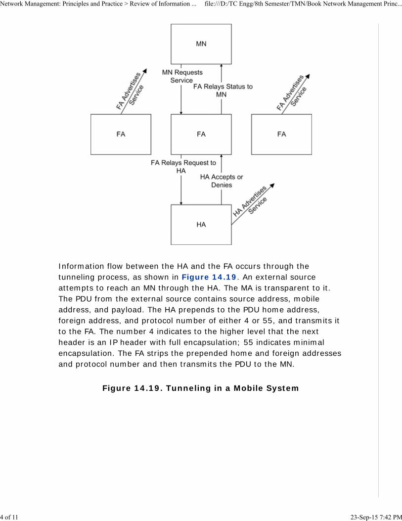
Information flow between the HA and the FA occurs through thetunneling process, as shown in Figure 14.19. An external sourceattempts to reach an MN through the HA. The MA is transparent to it.The PDU from the external source contains source address, mobileaddress, and payload. The HA prepends to the PDU home address,foreign address, and protocol number of either 4 or 55, and transmits itto the FA. The number 4 indicates to the higher level that the nextheader is an IP header with full encapsulation; 55 indicates minimalencapsulation. The FA strips the prepended home and foreign addressesand protocol number and then transmits the PDU to the MN.
Figure 14.19. Tunneling in a Mobile System
Network Management: Principles and Practice > Review of Information ... file:///D:/TC Engg/8th Semester/TMN/Book Network Management Princ...
4 of 11 23-Sep-15 7:42 PM

Table 14.3 presents mobile IP MIB groups. There are three groups:mobile node, foreign agent, and home agent. Each group is organizedas a set of related objects. The relationship is between objects withinthe same group or across different groups. For example,mipSystemGroup spans across all three groups andmaAdvertisementGroup spans FA and HA groups. mnSystemGroup andfaSystemGroup comprise intra-group-related objects.
Table 14.3. Mobile IP MIB Groups
Groups MobileNode
ForeignAgent
HomeAgent
Agent
mipSystemGroup X X X
mipSecAssociationGroup X X X
mipSecViolationGroup X X X
mnSystemGroup X
mnDiscoveryGroup X
mnRegistrationGroup X
maAdvertisementGroup X X
faSystemGroup X
faAdvertisementGroup X
faRegistrationGroup X
haRegistrationGroup X
Network Management: Principles and Practice > Review of Information ... file:///D:/TC Engg/8th Semester/TMN/Book Network Management Princ...
5 of 11 23-Sep-15 7:42 PM
Groups MobileNode
ForeignAgent
HomeAgent
haRegNodeCountersGroup x
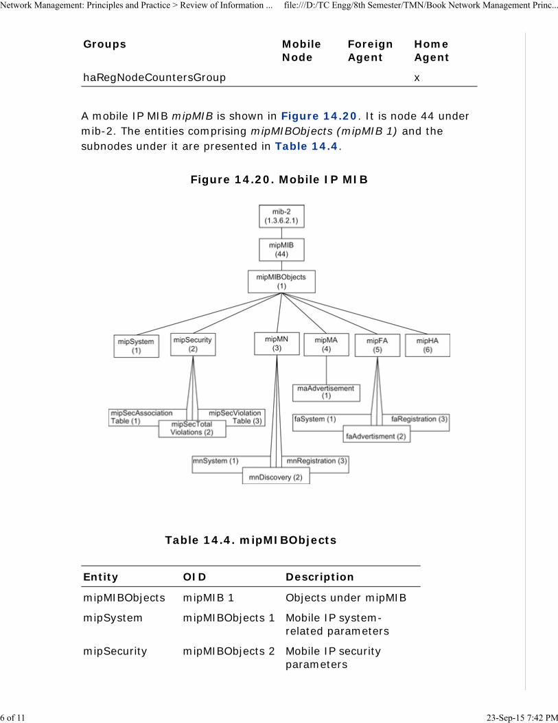
A mobile IP MIB mipMIB is shown in Figure 14.20. It is node 44 undermib-2. The entities comprising mipMIBObjects (mipMIB 1) and thesubnodes under it are presented in Table 14.4.
Figure 14.20. Mobile IP MIB
Table 14.4. mipMIBObjects
Entity OID Description
mipMIBObjects mipMIB 1 Objects under mipMIB
mipSystem mipMIBObjects 1 Mobile IP system-related parameters
mipSecurity mipMIBObjects 2 Mobile IP securityparameters
Network Management: Principles and Practice > Review of Information ... file:///D:/TC Engg/8th Semester/TMN/Book Network Management Princ...
6 of 11 23-Sep-15 7:42 PM

Entity OID Description
mipSecurity
AssociationTable mipSecurity 1 Security associationtable
mipSecTotal
Violations mipSecurity 2 Total number of securityviolations in the entity
mipSecViolation
Table mipSecurity 3 Security violationinformation
mipMN mipMIBObjects 3 Mobile node group
mnSystem mipMN 1 Mobile node systeminformation
mnDiscovery mipMN 2 Mobile node discoverycounter on solicitations,advertisements, andmoves
mnRegistration mipMN 3 Mobile node registrationtable
mipMA mipMIBObjects 4 Mobile agent group
maAdvertisement mipMA 1 Mobility agentadvertisementconfiguration tablepresent in both the MNand the FA
mipFA mipMIBObjects 5 FA group
faSystem mipFA 1 FA system information
faAdvertisement mipFA 2 FA advertisementinformation plus MAadvertisement group
faRegistration mipFA 3 FA visitors list
mipHA mipMIBObjects 6 HA registration groupand mobility binding list
We have already learned the important role that mobile IP plays inmobile communication. Mobility management consists of twocomponents, location management and handoff management.
Network Management: Principles and Practice > Review of Information ... file:///D:/TC Engg/8th Semester/TMN/Book Network Management Princ...
7 of 11 23-Sep-15 7:42 PM

Location management is a two-stage process. First, it enables thenetwork to discover the current attachment point of the mobile user fordata delivery. The MA periodically notifies the network of the MN’s newaccess point. The second stage is data delivery. Here the network isqueried for the mobile user’s location profile and the current position ofthe mobile host is found.
The second component is handoff (or handover) management thatenables the network to maintain a user’s connection as the mobileterminal continues to move and change its access point to the network.This is a three-stage process of initiation, connection establishment, anddata-flow management. During the initiation stage, either the user (anetwork agent) or changing network conditions identify the need forhandoff. In the connection–establishment stage, the network must findnew resources for the handoff connection and perform any additionalrouting operations. The final stage is data-flow control, where deliveryof data from the old connection path to the new connection path ismaintained.
Resource management deals with scheduling and call admission control(CAC), load balancing between access networks, dynamic control of RFspectrum, and power management. This impacts management ofbandwidth to provide multimedia broadband service, as well as handoffbetween cells to achieve quality of service.
In mobile cellular networks, when a mobile user moves from one cell toa different cell, “handoff” of the user needs to be accomplished withoutdropping the session. CAC is the process that controls whether anincoming call can be admitted or not. The resource control mechanismhas to allocate the limited bandwidth resources to users in an efficientway in order to guarantee the users’ QoS requirements. If the handofftarget cell does not have enough bandwidth to support this call, the callwill be forced to terminate. Handoff calls are commonly given a higherpriority in accessing bandwidth resources in order to provide a seamlessconnection for users. Call dropping during a handoff is mitigated byreserving bandwidth specifically for that function in each cell. Forbroadband service, handoff management becomes more complicated.The system needs to support, in addition to handoff in the same class ofservice, multiple classes of service where each class presents differentQoS requirements.
Handoff may also need to be done in intra-cell roaming of an MN. If thesignal falls below a threshold level of a subscriber’s SLA, transmission
Network Management: Principles and Practice > Review of Information ... file:///D:/TC Engg/8th Semester/TMN/Book Network Management Princ...
8 of 11 23-Sep-15 7:42 PM
can be dynamically switched to another frequency that is stronger.
Power management involves multiple components. [Pahlavan andKrishnamurthy, 2002] discusses power control, power-savingmechanisms, energy efficiency, and radio resource management. Powercontrol deals with mechanisms to dynamically control transmitter powerto reduce interference. Power-saving mechanisms and energy-efficientdesigns extend battery life. Radio resource management optimizestransmission by selecting the best spectral components.
Unfortunately, there are no standard MIBs defined for monitoring andmanaging the above resources. Proxy agents can be developed andused by vendors to implement these requirements.
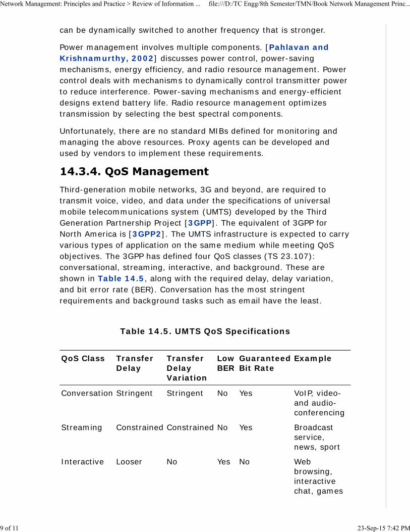
Third-generation mobile networks, 3G and beyond, are required totransmit voice, video, and data under the specifications of universalmobile telecommunications system (UMTS) developed by the ThirdGeneration Partnership Project [3GPP]. The equivalent of 3GPP forNorth America is [3GPP2]. The UMTS infrastructure is expected to carryvarious types of application on the same medium while meeting QoSobjectives. The 3GPP has defined four QoS classes (TS 23.107):conversational, streaming, interactive, and background. These areshown in Table 14.5, along with the required delay, delay variation,and bit error rate (BER). Conversation has the most stringentrequirements and background tasks such as email have the least.
Table 14.5. UMTS QoS Specifications
QoS Class TransferDelay
TransferDelayVariation
LowBER
GuaranteedBit Rate
Example
Conversation Stringent Stringent No Yes VoIP, video-and audio-conferencing
Streaming Constrained Constrained No Yes Broadcastservice,news, sport
Interactive Looser No Yes No Webbrowsing,interactivechat, games
Network Management: Principles and Practice > Review of Information ... file:///D:/TC Engg/8th Semester/TMN/Book Network Management Princ...
9 of 11 23-Sep-15 7:42 PM

QoS Class TransferDelay
TransferDelayVariation
LowBER
GuaranteedBit Rate
Example
Background No No Yes No Email, SMS,TFPtransactions
We have mentioned in the previous two sections the dependency of QoSon mobility and resource management. The QoS discussed here isapplicable only between the BS and the mobile stations. QoS on thecore network is achieved using wired network methodologies, such asintserv (integrated services) or diffserv (differentiated services).
Security is a major issue in mobile wireless communication. Securityrequirements for mobile wireless communication involve security indifferent parts of the network, both wired and wireless. Broadbandcommunication system is based on digital communication technologyTDM, TDMA, and CDMA. Air interface security is based on the wirelessapplication.
Wireless application protocol (WAP) and secured socket shell (SSL) arethe two approaches that are commonly used for secured wirelesscommunication. Although SSL is used extensively in a wired network,WAP is the common implementation in mobile wireless. It is based ontransport layer security (TLS) protocol. It does the normal securityfunctions, which include authentication, authorization, privacy, andaddress integrity.
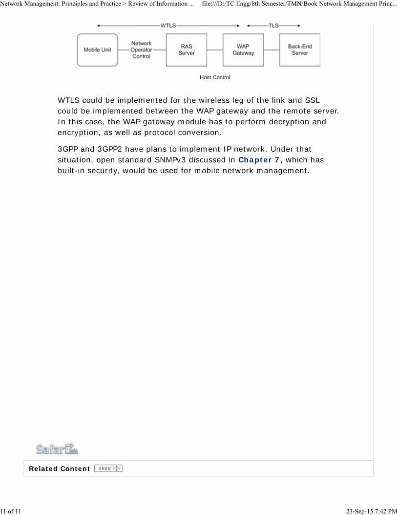
Figure 14.21 shows WAP architecture [Howell]. The MN is connectedto the WAP gateway through a network operator control and a remoteaccess server. The security protocol used is wireless TLS (WTLS). TheTLS protocol is used between the WAP gateway and remote server thatthe mobile subscriber is trying to access. Most security failures happenin the transition between the two. Robust security can be achieved bycareful design and implementation of the WAP gateway using availablesecurity tools.
Figure 14.21. Security Management in a Mobile System
Network Management: Principles and Practice > Review of Information ... file:///D:/TC Engg/8th Semester/TMN/Book Network Management Princ...
10 of 11 23-Sep-15 7:42 PM
Related Content
WTLS could be implemented for the wireless leg of the link and SSLcould be implemented between the WAP gateway and the remote server.In this case, the WAP gateway module has to perform decryption andencryption, as well as protocol conversion.
3GPP and 3GPP2 have plans to implement IP network. Under thatsituation, open standard SNMPv3 discussed in Chapter 7, which hasbuilt-in security, would be used for mobile network management.
Network Management: Principles and Practice > Review of Information ... file:///D:/TC Engg/8th Semester/TMN/Book Network Management Princ...
11 of 11 23-Sep-15 7:42 PM
Chapter 14. Broadband Wireless Access Networks > Satellite Networks
Although satellite communication is currently not ideally suited forbroadband communication, it is emerging as one in a limited manner.For example, VSAT (Figure 14.22) is a popular implementation ofdirect transmission to home (DTH) satellite access network. Somereasons for the revival of DTH are easy implementation, small andhighly directional antenna, and video compression technique. It is usedas a back-up link for communication by industrial organizations, as wellas to set up communication to rural and inaccessible areas such asmountainous regions.
Figure 14.22. VSAT Broadband Links
Network Management: Principles and Practice > Review of Information ... file:///D:/TC Engg/8th Semester/TMN/Book Network Management Princ...
1 of 3 23-Sep-15 7:41 PM

In the USA, VSAT operates in the Ku- and Ka-bands. In the Ku-band thedownlink is in the 12-GHz range and the uplink is in the 14-GHz range.In the Ka-band, the corresponding ranges are 29.5–30 GHz and19.7–20.2 GHz. Spectral allocations vary from country to country. Bothbands suffer from rain absorption and it is worse in the Ka-band than inKu-band. Although efforts to increase the speed in VSAT systems are inprogress, current systems operate at uplink speeds of about 40–60 kbpsand downlink speeds of 500 kbps.
The outdoor unit (ODU) consists of a power amplifier and anup-converter feeding into the antenna and low-noise blockdown-converter receiving signals from the antenna. The signal traversesat intermediate frequency over the coaxial cable between the ODU andthe indoor unit (IDU). The IDU includes the following components:modulator, demodulator, frequency synthesizer, encoder, and decoder.The normal interface to the customer network is Ethernet.
Network Management: Principles and Practice > Review of Information ... file:///D:/TC Engg/8th Semester/TMN/Book Network Management Princ...
2 of 3 23-Sep-15 7:41 PM
Standards are emerging in DTH. Digital video broadcast (DVB) is usedfor downstream broadcast. Upstream protocol is either DVB-RCS (DVBreturn channel system) or modified DOCSIS, DOCSIS-S [Steffes,2005].
VSAT uses geostationary earth orbit and hence appears stationary forthe ground station. The signal undergoes frequency conversion andamplification or regeneration in the satellite. The former is called a“bent-pipe” configuration and the latter regeneration configuration.Besides rain attenuation, VSAT also suffers from an end-to-endround-trip delay time of 0.5 seconds; i.e., from one terminal to anotherand back.
The NMS is usually located at the hub and monitors the hub and nodalsite equipment. Management data are acquired over satellite linkssharing bandwidth with the payload.
Objects to be managed are parameters associated with the antenna,transceivers, frequency converters, and power amplifiers. Since the totalbandwidth available is in the range of 40–500 kbps, assuming a limit of5% usage for management data, the bandwidth available in the satellitelinks for management is in the order of a few kilobits per second. Theusage of a standard SNMP protocol frame is expensive, and henceefficient proprietary protocols are implemented. Management featuresand parameters that are implemented are also limited due to bandwidthconstraint.
Network Management: Principles and Practice > Review of Information ... file:///D:/TC Engg/8th Semester/TMN/Book Network Management Princ...
3 of 3 23-Sep-15 7:41 PM
Chapter 14. Broadband Wireless Access Networks > Exercises
1. A satellite is transmitting 10 watts and is positioned at 2miles over the earth receiver. Assume that the antenna gainof the transmitter and the receiver are each equal to 1.6and the frequency of operation is at 4.8 GHz. Calculate thepower and the latency (propagation delay) of the receivedsignal.
2. A terrestrial wireless point-to-point broadbandcommunication system is established at 2.4 GHz. Theheight of the transmitter and the receiver antenna is each50 meters and the separations 10 kilometers. The receiversensitivity is 10-5 watts. Calculate the power needed at thetransmitter using a two-ray propagation model. Assume thegain of the antenna as 2 both at the transmitter and thereceiver.
3. Latency is a problem for interactive communication viasattelite. Calculate the orbital altitude and round-trip delaytime between two stations on the ground communicatingvia a geostationary satellite. Assume the radius of the orbitis 42,164 kilometers and the radius of the earth is 6,378kilometers.
4. Fill the ifTable objects for a three-sector base station andone subscriber station for each sector shown in Table 14.1and Table 14.2. The tables should represent reasonableand valid values as they appear in the database of an NMS.Assume that sector 1 is completely functional, sector 2 isunder failure condition, and sector 3 is under maintenancemode. All subscriber stations are active.
5. Identify the managed objects and the MIBs that were usedto acquire the information in Tables 14.1 and 14.2.
6.What MIB table would you use to measure theQoS of service flow in a fixed wireless systembetween the base station and the subscriberstation?
a.
Network Management: Principles and Practice > Review of Information ... file:///D:/TC Engg/8th Semester/TMN/Book Network Management Princ...
1 of 2 23-Sep-15 7:41 PM

Define latency and jitter for service flow in a fixedwireless system
b.
Write the specific managed objects associatedwith latency and jitter
c.
7. In designing a mobile network, what is the protocol youwould use for:
Communication between the foreign agent andthe mobile agents associated with that cell?
a.
Communication between the foreign agent andthe home agent?
b.
8. In Figure 14.19, assume the home network as a class Bnetwork and foreign nodes belonging to a class C network.Fill in the data frame with the appropriate addressesbetween each pair of nodes.
Network Management: Principles and Practice > Review of Information ... file:///D:/TC Engg/8th Semester/TMN/Book Network Management Princ...
2 of 2 23-Sep-15 7:41 PM

Chapter 14. Broadband Wireless Access Networks > Summary
Network Management: Principles and Practice > Review of Information ... file:///D:/TC Engg/8th Semester/TMN/Book Network Management Princ...
1 of 2 23-Sep-15 7:43 PM

Related Content
In this chapter, we addressed the basic principles of wirelesscommunication that are required to understand wireless accessnetworks and their management. The key areas covered are free-spacepropagation that is applicable to satellite and mobile communicationsand two-ray propagation that terrestrial wireless access networks arebased on. We also discussed the fading phenomenon that separateswireless access networks from those of wired access networks.
We discussed the three major categories of fixed wireless broadbandaccess networks, namely MMDS, LMDS, and IEEE 802.16/WiMax. MMDShas been deployed in rural areas and has adopted wired cabletechnology defined by DOCSIS standards. LMDS is also based onDOCSIS standards although other technologies such as GPRS are used.Network management of DOCSIS-based MMDS and LMDS has takenadvantage of standards developed for the management of cable accessnetworks.
WiMax network is an outgrowth of IEEE 802.16, which is the generalizedstandard for fixed wireless access networks. This technology is seriouslyconsidered for metropolitan access network and will compete with cableand DSL technologies. However, it has been slow in getting deployeddue to technical, as well as competitive reasons. MIBs have beenspecified for this to implement remote network management.
We discussed mobile cellular wireless network primarily from the IPnetwork point of view, although proprietary technologies are mostlyused for predominantly voice-based network. Mobile IP plays animportant role in the implementation of broadband mobile wirelessincluding management of it. This was addressed in detail.
VSAT was described as emerging DTH technology for broadband accessnetwork. It has several advantages and disadvantages for use inbroadband communication. Because of its geographical distribution,remote network management system is a necessity. However, due tobandwidth constraint, features of the system are usually limited.
Network Management: Principles and Practice > Review of Information ... file:///D:/TC Engg/8th Semester/TMN/Book Network Management Princ...
2 of 2 23-Sep-15 7:43 PM