networking fundamentals fiber-optic cable. osi model data unitlayerfunction host layers data 7....
TRANSCRIPT
Networking Fundamentals
Fiber-OpticCable
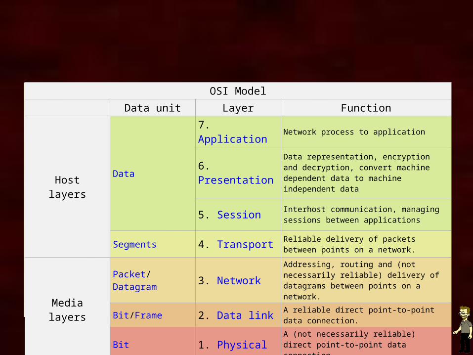
OSI ModelData unit Layer Function
Hostlayers
Data
7. Application Network process to application
6. PresentationData representation, encryption and decryption, convert machine dependent data to machine independent data
5. Session Interhost communication, managing sessions between applications
Segments 4. Transport Reliable delivery of packets between points on a network.
Medialayers
Packet/Datagram 3. NetworkAddressing, routing and (not necessarily reliable) delivery of datagrams between points on a network.
Bit/Frame 2. Data link A reliable direct point-to-point data connection.
Bit 1. Physical A (not necessarily reliable) direct point-to-point data connection.
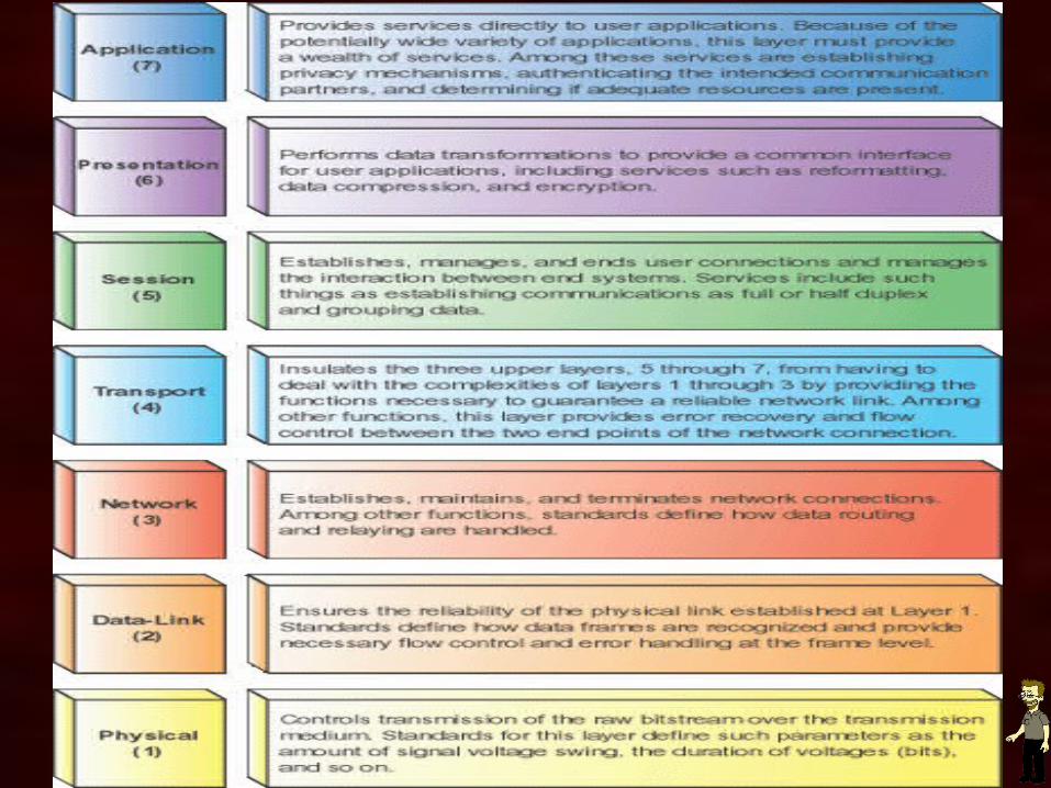
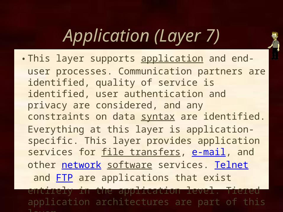
Application (Layer 7)• This layer supports application and end-user processes.
Communication partners are identified, quality of service is identified, user authentication and privacy are considered, and any constraints on data syntax are identified. Everything at this layer is application-specific. This layer provides application services for file transfers, e-mail, and other network software services. Telnet and FTP are applications that exist entirely in the application level. Tiered application architectures are part of this layer.
Presentation (Layer 6)• This layer provides independence from differences in
data representation (e.g., encryption) by translating from application to network format, and vice versa. The presentation layer works to transform data into the form that the application layer can accept. This layer formats and encrypts data to be sent across a network, providing freedom from compatibility problems. It is sometimes called the syntax layer.
• Mostly useless
Session (Layer 5)• This layer establishes, manages and
terminates connections between applications. The session layer sets up, coordinates, and terminates conversations, exchanges, and dialogues between the applications at each end. It deals with session and connection coordination.
• Mostly useless.
Transport (Layer 4)• This layer provides transparent transfer of data between end
systems, or hosts, and is responsible for end-to-end error recovery and flow control. It ensures complete data transfer.
• Layer 4 data units are also called packets, but when you're talking about specific protocols, like TCP, they're "segments" or "datagrams" in UDP. This layer is responsible for getting the entire message, so it must keep track of fragmentation, out-of-order packets, and other perils. Layer 4 provides end-to-end management of communication. Some protocols, like TCP, do a very good job of making sure the communication is reliable. Some don't really care if a few packets are lost--UDP is the prime example.
Network (Layer 3)• This layer provides switching and routing
technologies, creating logical paths, known as virtual circuits, for transmitting data from node to node. Routing and forwarding are functions of this layer, as well as addressing, internetworking, error handling, congestion control and packet sequencing.
• IP is part of layer 3, along with some routing protocols, and ARP (Address Resolution Protocol). Everything about routing is handled in layer 3. Addressing and routing is the main goal of this layer.

Data Link (Layer 2)• At this layer, data packets are encoded and decoded into bits.
It furnishes transmission protocol knowledge and management and handles errors in the physical layer, flow control and frame synchronization. The data link layer is divided into two sub layers: The Media Access Control (MAC) layer and the Logical Link Control (LLC) layer. The MAC sub layer controls how a computer on the network gains access to the data and permission to transmit it. The LLC layer controls framesynchronization, flow control and error checking.
• Ethernet, among other protocols, lives on Layer 2.• MAC address, switches, or network cards
Physical (Layer 1)• This layer conveys the bit stream - electrical
impulse, light or radio signal -- through the network at the electrical and mechanical level. It provides the hardware means of sending and receiving data on a carrier, including defining cables, cards and physical aspects. Fast Ethernet, RS232, and ATM are protocols with physical layer components.
CHARACTERISTICS
Fiber-OpticCable
Characteristics of Fiber-Optic Cable
• Security• Immunity to Electromagnetic Interference• Weight and Size• Safety• Bandwidth• Corrosion and Water Resistance• Greater Distances
Security
No “Vampire” tapshard to eaves-dropI don’t think it’s impossible – just expensive
and requires specialized equipmentand know-how
Immune to EMP
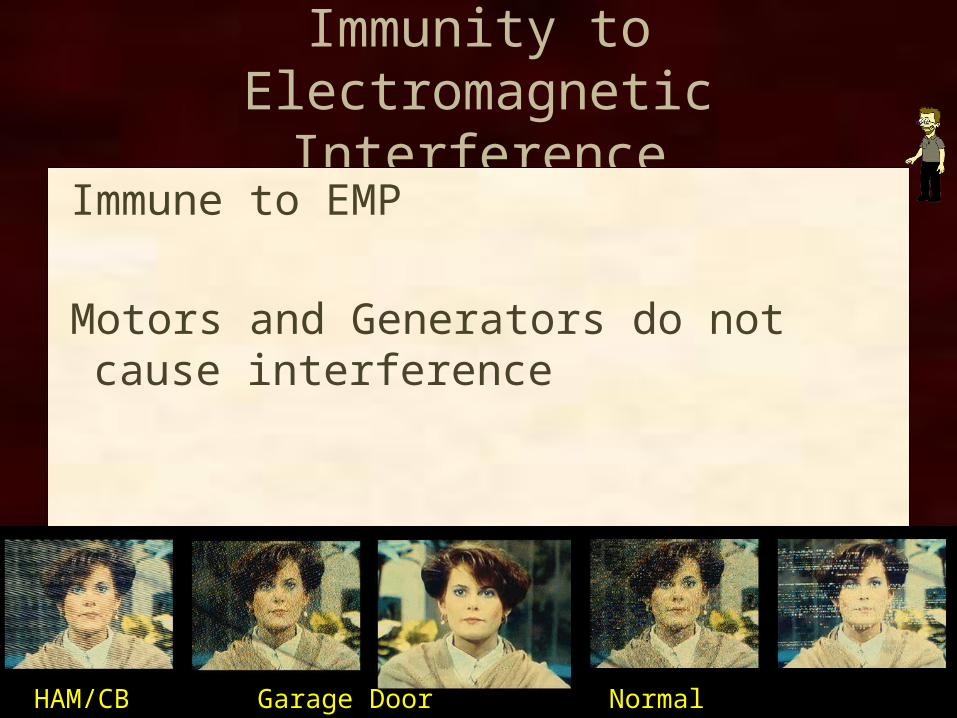
Immunity to Electromagnetic Interference
Immune to EMP
Motors and Generators do not cause interference
HAM/CB Garage Door Normal Computer Hair Dryer
Weight and Size
Lighter than copper (1/10)
Smaller diameter than copper (10/1)
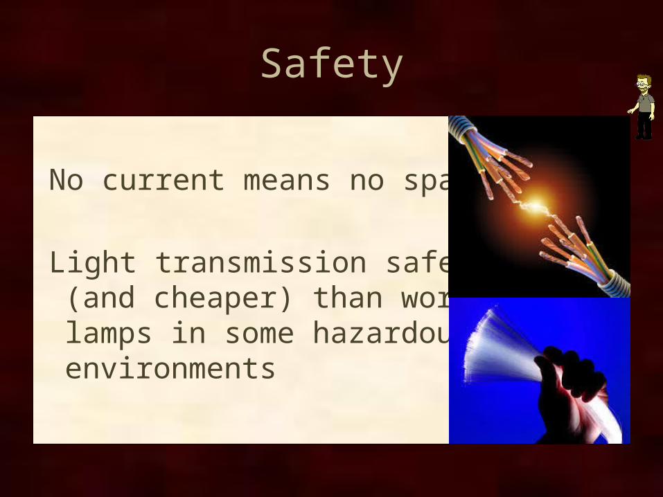
Safety
No current means no sparks
Light transmission safer (and cheaper) than work lamps in some hazardous environments
Bandwidth
Compared to copper:higher frequency means greater bandwidthno impedance limitationsno inductive reactance (at high frequencies
copper can lose conduction)
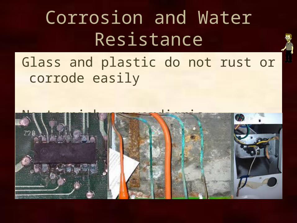
Corrosion and Water Resistance
Glass and plastic do not rust or corrode easily
No tarnish or verdigris (oxidation/rust)
Greater Distances
Copper networks segments mostly limited to 100 meters or less.
fiber-optic can support distances over 20 kilometers.
FDDI applications can be 200 km (124 mi).
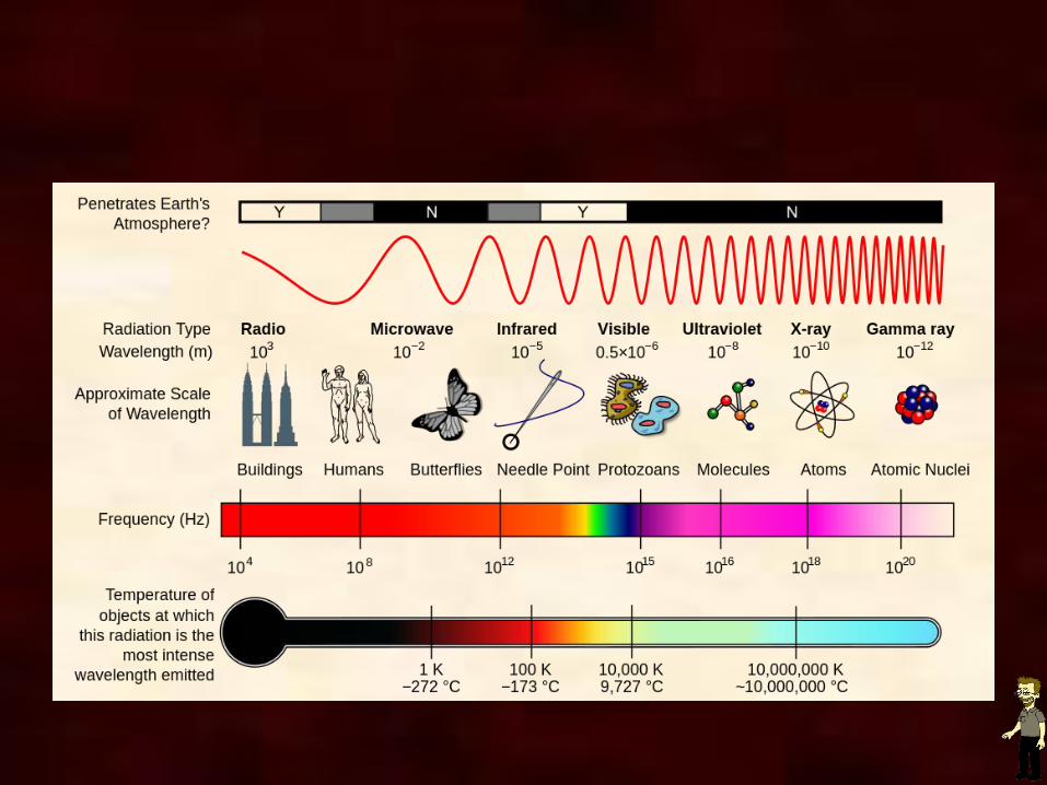
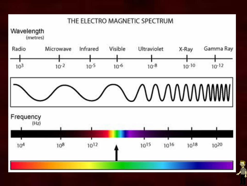
The Nature of Light
light energy waves - electromagneticelectromagnetic waves need no carrier (can
travel through a vacuum) unlike sound wavesinstead of frequency wavelengthvisible light roughly 400 - 800 nmnano meter is meter/billionfiber-optic commonly use 850nm - 1550nm
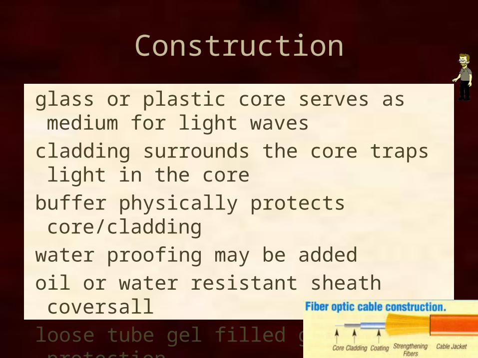
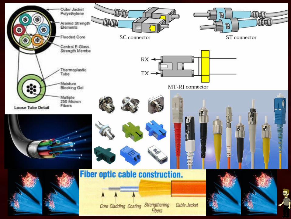
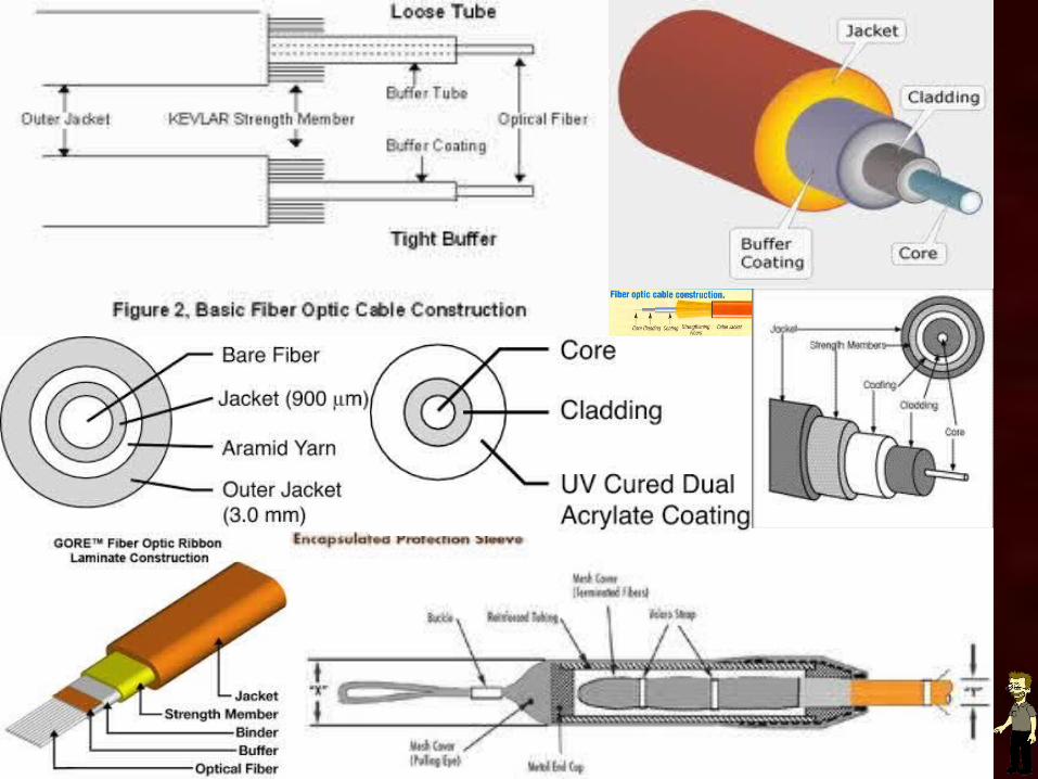
Construction
glass or plastic core serves as medium for light waves
cladding surrounds the core traps light in the corebuffer physically protects core/claddingwater proofing may be addedoil or water resistant sheath coversallloose tube gel filled greater protectiontight buffer less space more fragile
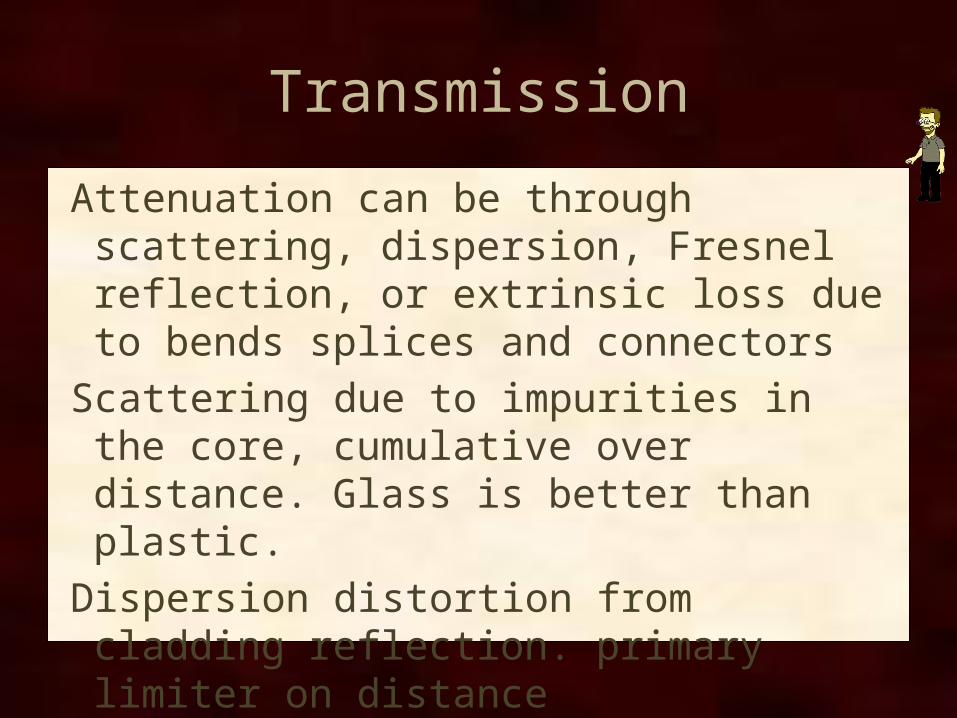
Transmission
Attenuation can be through scattering, dispersion, Fresnel reflection, or extrinsic loss due to bends splices and connectors
Scattering due to impurities in the core, cumulative over distance. Glass is better than plastic.
Dispersion distortion from cladding reflection. primary limiter on distance
Fresnel reflection occurs at connectors


Specifications
Multimode fiber optic cable - large core diameterSingle-mode fiber optic cable - small core diameter
- matched to wavelength to control dispersion - allows greater distances
Micrometers - um - meter/millionCable identified as core/cladding
multimode eg 50/125 65.5/125single-mode eg 8.3/125
802.3 STANDARDS
Fiber-OpticCable
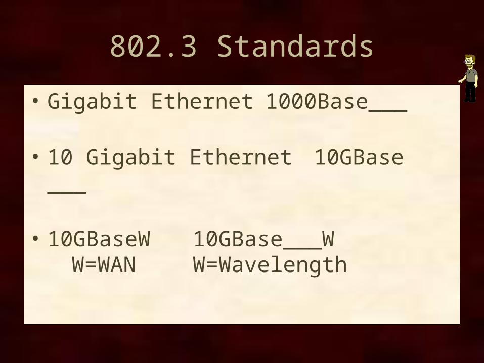
802.3 Standards
• Gigabit Ethernet 1000Base___
• 10 Gigabit Ethernet 10GBase ___
• 10GBaseW 10GBase___WW=WAN W=Wavelength
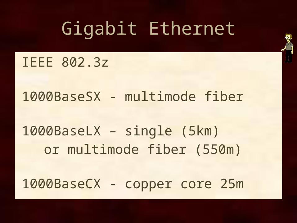
Gigabit Ethernet
IEEE 802.3z
1000BaseSX - multimode fiber
1000BaseLX – single (5km) or multimode fiber (550m)
1000BaseCX - copper core 25m
10 Gigabit Ethernet
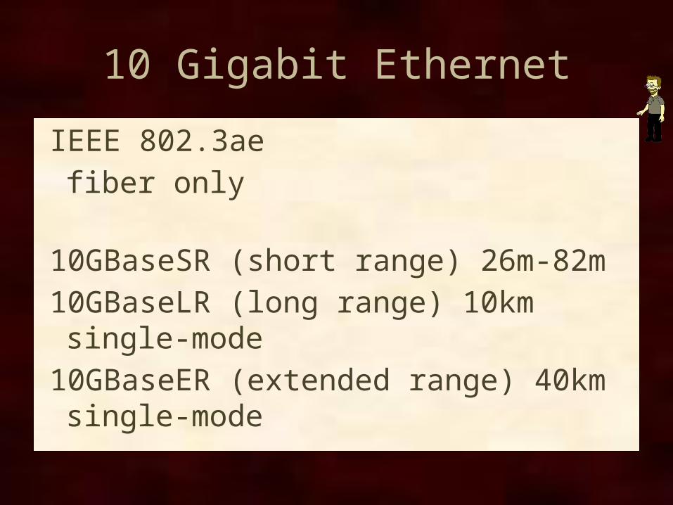
IEEE 802.3aefiber only
10GBaseSR (short range) 26m-82m10GBaseLR (long range) 10km single-mode10GBaseER (extended range) 40km single-mode
10GBaseW
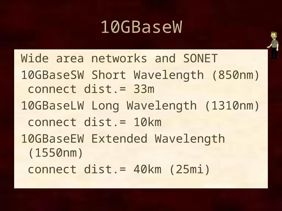
Wide area networks and SONET10GBaseSW Short Wavelength (850nm)
connect dist.= 33m10GBaseLW Long Wavelength (1310nm)
connect dist.= 10km10GBaseEW Extended Wavelength (1550nm)
connect dist.= 40km (25mi)
FDDI
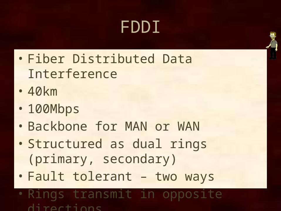
• Fiber Distributed Data Interference• 40km• 100Mbps• Backbone for MAN or WAN• Structured as dual rings (primary, secondary)• Fault tolerant – two ways• Rings transmit in opposite directions• Token ring
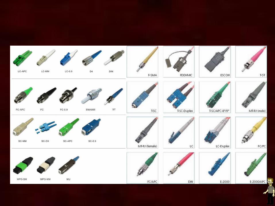
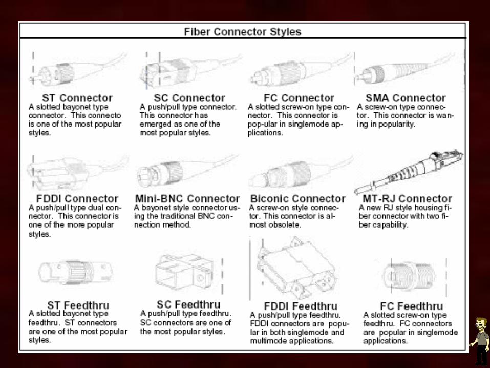
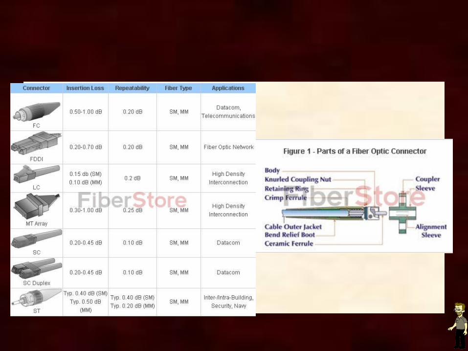
Fiber-Optic Cable Connectors
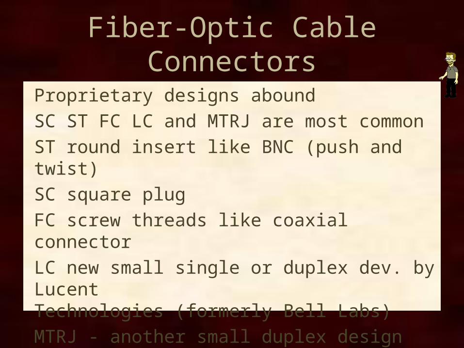
Proprietary designs aboundSC ST FC LC and MTRJ are most commonST round insert like BNC (push and twist)SC square plugFC screw threads like coaxial connectorLC new small single or duplex dev. by LucentTechnologies (formerly Bell Labs)MTRJ - another small duplex designSee page 135
INSTALLATION AND TROUBLESHOOTING
Fiber-OpticCable
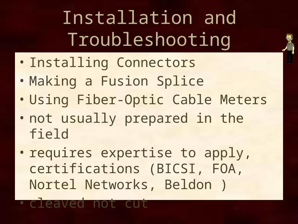
Installation and Troubleshooting
• Installing Connectors• Making a Fusion Splice• Using Fiber-Optic Cable Meters• not usually prepared in the field• requires expertise to apply, certifications
(BICSI, FOA, Nortel Networks, Beldon )• cleaved not cut

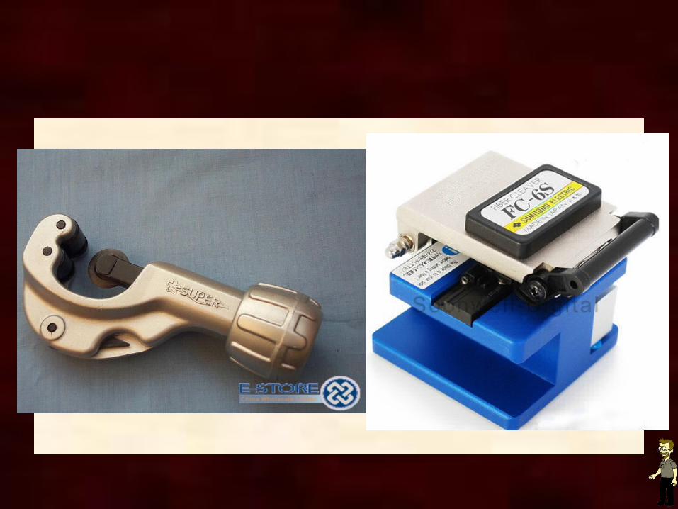
Installing Connectors
Design/measure prior to installation/supplySplicing difficulties include dirt and alignmentGlass cores must be cleaved carefullyPlastic cores must be cut carefully
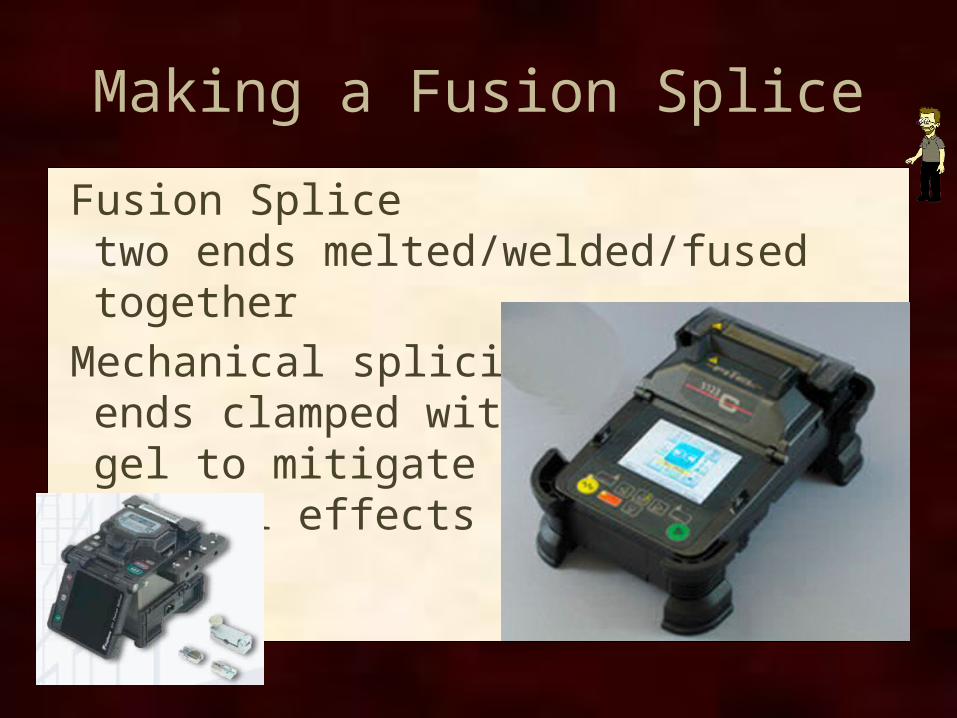
Making a Fusion Splice
Fusion Splicetwo ends melted/welded/fused together
Mechanical splicingends clamped with gel to mitigate Fresnel effects
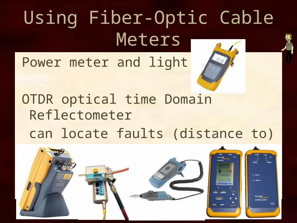
Using Fiber-Optic Cable Meters
Power meter and light source
OTDR optical time Domain Reflectometercan locate faults (distance to)rent don’t buy