neurosurgical operative approaches: what the neuroradiologist … · calvarial anatomy the...
TRANSCRIPT

Neurosurgical OperativeApproaches:
What the Neuroradiologist Needs to
Know
Ryan Holdsworth, MD
eEdE-54

Purpose
Imaging plays a key role in the preoperative and
postoperative evaluation of neurosurgical patients, and
neuroradiologists should be facile with the various
approaches utilized in intracranial operations.
This exhibit will demonstrate neurosurgical approaches
for operations such as cranial decompression, tumor
resection, and aneurysm clipping.
Our goal is to highlight the most common neurosurgical
approaches, including anatomic considerations, imaging
appearance, and imaging of potential complications.

Normal Anatomy and Basic Craniotomy
Technique
Before delving into the types and imaging appearance of
various craniotomies, we must first understand normal
cranial anatomy.
A review basic craniotomy technique is also useful.

Scalp Anatomy
The scalp extends anteroposteriorly from the supraorbital ridge to the superior nuchal line and laterally to the zygomatic arch and external auditory meatus.
The scalp is composed of five layers from superficial to deep: 1. skin, 2. subcutaneous tissue, 3. galea aponeurotica, 4. loose areolar connective tissue, and 5. periosteum.
The connective tissue layer also contains traversing vessels and three primary muscle groups (frontalis, occipitalis, and temporalis).

Scalp Anatomy - CT
Coned down axial soft tissue window gray scale and color overlay CT images of the superior right temporal fossa demonstrate the 5 layers of the scalp: 1. skin (green), 2. subcutaneous tissue (yellow), 3. galea aponeurotica (blue), 4. loose areolar tissue (orange) including temporalis muscle (teal), and 5. thin periosteum (red).

Scalp Anatomy - MRI
Coned down non contrast enhanced axial T1 weighted gray scale and color overlay MRI images of the superior right temporal fossa demonstrate the 5 layers of the scalp: 1. skin (green), 2. subcutaneous tissue (yellow), 3. galea aponeurotica (blue), 4. loose areolar tissue (orange) including temporalis muscle (teal), and 5. thin periosteum (red).

Calvarial Anatomy
The calvarium, or skull vault, is composed of inner and outer tables of cortical bone surrounding a central area of marrow containing cancellous bone.
A combination of a number of different bones (frontal, parietal, temporal, sphenoid, maxillary, ethmoid, zygomatic, and occipital) comprise the outer calvarial vault which are joined together by fibrous joints composed of Sharpey’s fibers called sutures.
The inner and outer tables are covered by a thin layer of periosteum.
The underlying dura mater is comprised of the combination of the inner periosteum and the dura mater proper.
In the native calvarium, the inner periosteum is tightly opposed to the sutures which typically restricts the flow of fluid collections in the epidural space.

Calvarial Anatomy - CT
Coned down axial bone window gray scale and color overlay CT images of the junction of the left frontal (F) and parietal (P) bones demonstrate the outer table (green) and inner table (blue) of cortical bone surrounding the central cancellous bone. Note the obliquely oriented coronal suture (red) joining the two bones tightly together.
Calvarial Anatomy - Bones
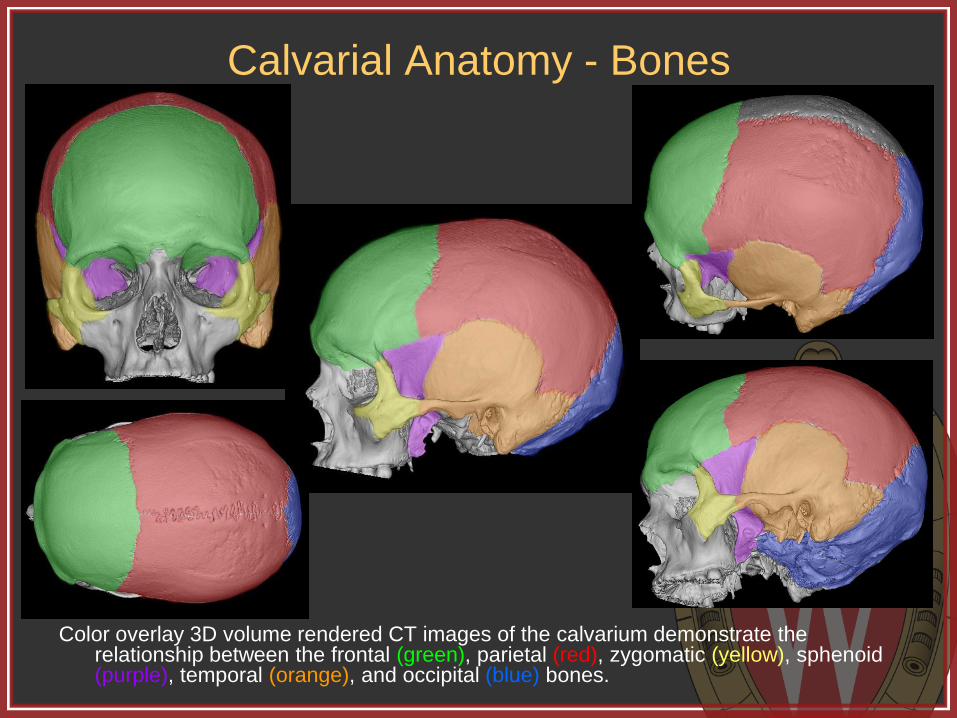
Color overlay 3D volume rendered CT images of the calvarium demonstrate the relationship between the frontal (green), parietal (red), zygomatic (yellow), sphenoid (purple), temporal (orange), and occipital (blue) bones.

Calvarial Anatomy - Sutures
Color overlay 3D volume rendered CT images of the calvarium demonstrate the relationship between the coronal (green), sagittal (red), squamosal (orange),sphenofrontal (yellow), sphenoparietal (teal), sphenotemporal (purple), lambdoid (blue), parietomastoid (dark green), occipitomastoid (maroon) , frontozygomatic (dark orange) , temporozygomatic (gray), and zygomaticomaxillary (dark blue) sutures.

Basic Craniotomy Technique
The patient is positioned to ensure proper access, then prepped and draped appropriately.
An incision is made to the depth of the periosteum to create a large myocutaneous flap, which is then reflected away from the planned craniotomy.
One or more burr holes are created through the calvarium using a manual or automatic drill.
A side cutting router is then used to connect the burr holes and create a bone flap completely separate from the remaining calvarium.
An elevator is then used to free the craniotomy flap from the underlying dura and the flap is removed.
After the intracranial portion of the operation is concluded, the bone flap is typically replaced and secured to the remainder of the calvarium with small titanium plates and screws.

Types of Craniotomies We will now review the most common types of surgicial
approaches used for intracranial access.
First, a few terms:
Craniectomy = excision of a portion of the skull
Cranioplasty = surgical correction of a skull defect
Craniotomy = opening into the skull, which can be used either to describe isolated holes (trephination) or, more typically, the removal for intracranial access with subsequent replacement of a skull flap in one operation.

Burr Hole
Small hole within the calvarium.
Indications: evacuation of simple fluid collections (liquid chronic subdural hematoma or effusion), placement of a device (intracranial pressure monitor, ventricular shunt catheter, endoscope, stimulator lead, etc), or as the first step in craniotomy flap formation.
Appear as well defined round holes within the calvarium traversing both the outer and inner tables.
Post-operatively, may be covered by a round titanium cover.
*3D volume rendered CT with overlay
demonstrates the typical location for a
burr hole (gray circle) for placement of an
external ventricular drainage catheter or
frontal ventriculoperitoneal shunt
(approximately 3 cm lateral from midline
and 1 cm anterior to the coronal suture).

Burr Holes
Axial non-contrast enhanced CT
demonstrates subacute to chronic
appearing subdural hemorrhage along the
left cerebral convexity which was
subsequently evacuated by anterior and
posterior parietal burr holes.
Postoperative axial non-contrast enhanced
CT in the same patient demonstrates the
expected appearance of two burr holes
along the left calvarium. Note the round,
smooth margin, involvement of both the
inner and outer table, and presence of
metallic burr hole covers.

“Mini” Craniotomy
A small craniotomy, often within the frontal or parietal bones, typically using one or two burr holes.
Indications are the same for burr holes, but the “mini” craniotomy is used when slightly wider access is needed for things such as placement of grid electrodes or subdural drains, or for the evacuation of more complicated fluid collections (empyema or subacute subdural hematoma).
*3D volume rendered CT with overlay
demonstrates the expected planning for an
anterior parietal “mini” craniotomy utilizing a
single burr hole (gray circle) and free handed
router track (curved gray line) for removal of a
small calvarial flap (green).

“Mini” Craniotomy
Preoperative (top left) and immediate postoperative (top
middle and top right) axial CT images for the same patient
as the prior burr hole example. The patient developed a
recurrent subdural bleed requiring “mini” craniotomy
evacuation and subdural drain placement using the same
anterior burr hole as in the prior operation. 3D volume
rendered CT image (bottom right) demonstrates the
location and appearance of the anterior “mini” craniotomy
and existing posterior burr hole. Note the star shaped
covers over the burr holes and small dogbone plates
securing the craniotomy.

Craniectomy
Craniectomy involves removal of a portion of the calvarium with the scalp subsequently closed without the bone in place.
The removed bone may be discarded or saved for future replacement.
Indications for craniectomy typically involve decompression to create room for cerebral swelling (trauma, malignant MCA territory infarction), or to reduce anatomic mass effect (Chiari malformation).
Other indications include infection/osteomyelitis and calvarial tumors.
*3D volume rendered CT with overlay
demonstrates the expected planning for a
large left sided hemicraniectomy using multiple
burr holes (gray circles) and side cutting router
tract (curvilinear gray line) to remove a large
calvarial flap (green) for decompression of the
left cerebral hemisphere .

Hemicraniectomy
Diffusion (top left) and cerebral blood volume map (top middle) MR images demonstrate left MCA territory infarction as sequela of occlusion of the distal left internal carotid artery (top right – yellow arrow). The patient developed malignant cerebral swelling. Post-operative CT (bottom left and bottom middle) and non contrast enhanced T2 weighted (bottom right) axial images demonstrate cerebral swelling and external herniation through the newly created large calvarial defect.
Hemicraniectomy
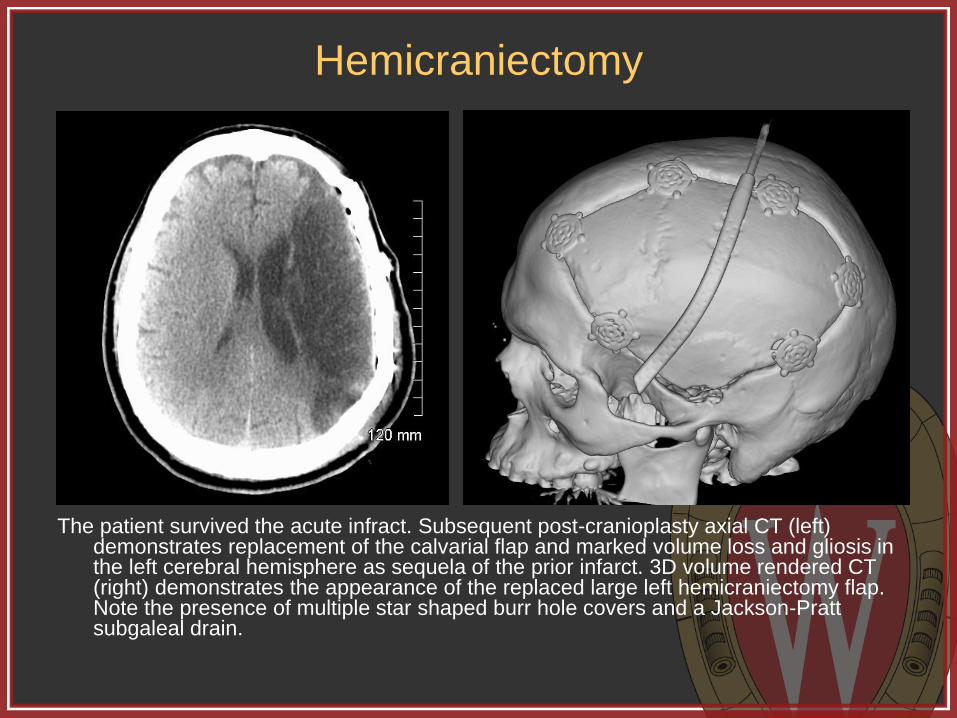
The patient survived the acute infract. Subsequent post-cranioplasty axial CT (left) demonstrates replacement of the calvarial flap and marked volume loss and gliosis in the left cerebral hemisphere as sequela of the prior infarct. 3D volume rendered CT (right) demonstrates the appearance of the replaced large left hemicraniectomy flap. Note the presence of multiple star shaped burr hole covers and a Jackson-Pratt subgaleal drain.

Hemicraniotomy
Axial noncontrast axial CT image on a different patient demonstrates an acute right cerebral convexity subdural hemorrhage with mass effect and leftward subfalcine herniation (top right). Post operative soft tissue (top middle) and bone window (top right) images demonstrate the expected appearance status post hematoma evacuation with decreased mass effect. 3D volume rendered CT (bottom right) demonstrates the appearance of the large calvarial flap. Note the presence of a subdural drain on all post-operative images.

Hemicraniectomy
Follow-up contrast enhanced axial CT of the same patient (top left) demonstrates the presence of a peripherally enhancing fluid collection consistent with post operative infection and subdural empyema. Immediate post-operative CT images (top middle, top right) demonstrate removal of the infected bone flap and irrigation of the operative bed. 3D volume rendered CT image (bottom right) demonstrates the removal of the large right fronto-temporo-parietal craniotomy flap.

Cranioplasty
Cranioplasty can refer plastic surgery for alteration or reconstruction of the calvarium, but can also refer to repair of a calvarial defect status post craniectomy.
Cranioplasty can involve replacement of the originally removed (and preserved) calvarial flap, but can also be accomplished using a variety of commercially prepared materials.
Cranioplasty is typically performed within 3 months post craniectomy to avoid too much tissue retraction in the scalp.
*Molded titanium (top left) and custom
composite PEEK (top right) cranioplasty
materials. Multiple titanium bone plates and
round burr hole covers (bottom image) used in
securing cranioplasty flaps.
Images courtesy KLS Martin, Inc.
(www.klsmartinnorthamercia.com/products)
Cranioplasty
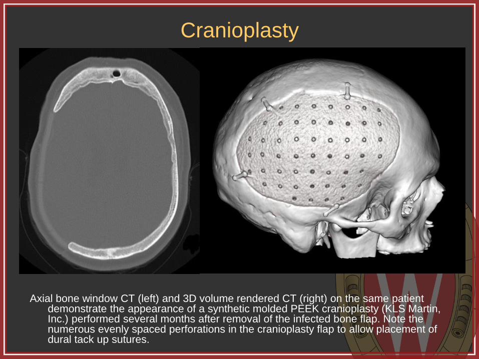
Axial bone window CT (left) and 3D volume rendered CT (right) on the same patient demonstrate the appearance of a synthetic molded PEEK cranioplasty (KLS Martin, Inc.) performed several months after removal of the infected bone flap. Note the numerous evenly spaced perforations in the cranioplasty flap to allow placement of dural tack up sutures.

Standard Craniotomies
Next, we will review the most common craniotomies and surgical approaches using case examples including:
Bifrontal
Parietal
Frontotemporoparietal
Frontosphenotemporal (pterional)
Orbitozygomatic
Suboccipital
Less commonly performed transphenoidal, retrosigmoid, and translabyrinthine approaches, among others, are not covered in this presentation for brevity.
Bifrontal
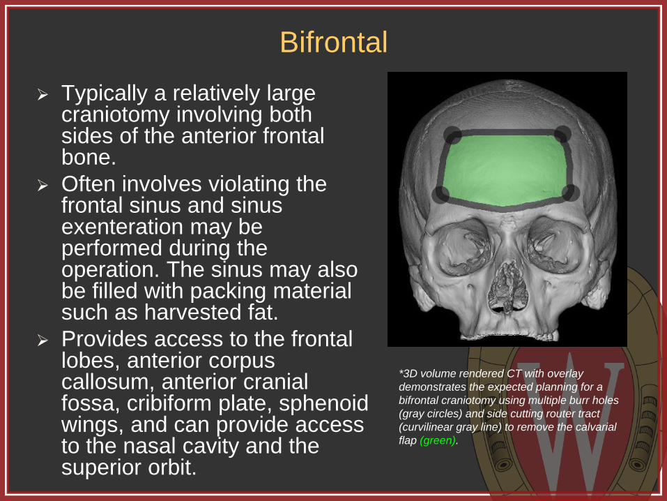
Typically a relatively large craniotomy involving both sides of the anterior frontal bone.
Often involves violating the frontal sinus and sinus exenteration may be performed during the operation. The sinus may also be filled with packing material such as harvested fat.
Provides access to the frontal lobes, anterior corpus callosum, anterior cranial fossa, cribiform plate, sphenoid wings, and can provide access to the nasal cavity and the superior orbit.
*3D volume rendered CT with overlay
demonstrates the expected planning for a
bifrontal craniotomy using multiple burr holes
(gray circles) and side cutting router tract
(curvilinear gray line) to remove the calvarial
flap (green).

Bifrontal
Axial (top left) and sagittal (top middle) post contrast T1 weighted images demonstrate a large, expansile, enhancing mass centered within the superior nasal cavity and frontal sinus. Note the mass eroding through the anterior wall of the frontal sinus. Post operative axial (top right) and sagittal (bottom right) post contrast T1 weighted images demonstrate the appearance status post bifrontal craniotomy for removal of the mass.

Bifrontal
Axial soft tissue (top left) and bone window (top middle) and sagittal reconstruction (top right) CT images demonstrate the appearance of the operative bed status post bifrontal craniotomy for removal of the mass. Note the presence of fat packing within the region of the frontal sinus which could be confused with air on the narrower soft tissue window width. 3D volume rendered CT (bottom right) shows the appearance of the calvarial flap. Note the absence of bone where the tumor had eroded through the frontal sinus. Also note the second small bone flap created for additional exposure.

Parietal
Smaller craniotomies involving a single bone are typically used to access a cerebral lesion subjacent to the craniotomy.
The same principles involved in a parietal craniotomy can also be applied to an isolated frontal or temporal craniotomy. We are using a parietal craniotomy in this example.
A midline craniotomy spanning the sagittal suture involving a portion of both parietal bones is often referred to as a vertex craniotomy.
*3D volume rendered CT with overlay
demonstrates the expected planning for a right
sided posterior parietal craniotomy using
multiple burr holes (gray circles) and side
cutting router tract (curvilinear gray line) to
remove the calvarial flap (green).

Parietal
Axial post contrast T1 weighted (top left) and T2 FLAIR (top middle) images demonstrate an enhancing cystic and solid mass with marked surrounding vasogenic edema within the posterior right parietal lobe. Post contrast axial T1 weighted (top right) and T2 FLAIR (bottom right) demonstrate expected post operative changes from right posterior parietal craniotomy for resection of what turned out to be a metastatic lesion. Note the T2 hyperintense edema and associated enhancement within the scalp, a normal finding in the immediate post operative period.

Parietal
Axial bone window (left) and 3D volume rendered (right) CT images in the same patient demonstrate the appearance of the right posterior parietal craniotomy for resection of the metastatic lesion. Note the smooth, round burr hole and overlying titanium burr hole cover. Also note the smooth margins of the side cutting router tract. This patient also has a left frontal external ventricular drainage catheter, which is partially seen on these images.

Frontotemporoparietal
Relatively large craniotomy involving portions of the frontal, temporal, and parietal bones.
Very large FTP craniotomies can also be termed “hemi-craniotomies” as previously illustrated.
Indications primarily include hematoma evacuation or tumor resection.
Accessible intracranial contents include the cerebral hemisphere and Sylvian fissure.
*3D volume rendered CT with overlay
demonstrates the expected planning for a left
sided frontotemporoparietal craniotomy using
multiple burr holes (gray circles) and side
cutting router tract (curvilinear gray line) to
remove the calvarial flap (green).

Frontotemporoparietal
Axial noncontrast CT (top left) demonstrates a large acute traumatic subdural hematoma with significant mass effect and rightward subfalcine herniation. Initial post-operative CT (top second from left) demonstrates evacuation of the hematoma and decreased herniation. The calvarial flap was replaced as opposed to being removed in a craniectomy. Note the presence of a subdural drain and high attenuation duraplasty material. Contrast enhanced axial CT (top second from right) performed some time later demonstrates a fluid collection within the subdural space as well as thick subarachnoid enhancement consistent with infection. The patient was taken to the operating room for irrigation and removal of the calvarial flap as demonstrated the in the post operative CT (right top and bottom).
Frontotemporoparietal
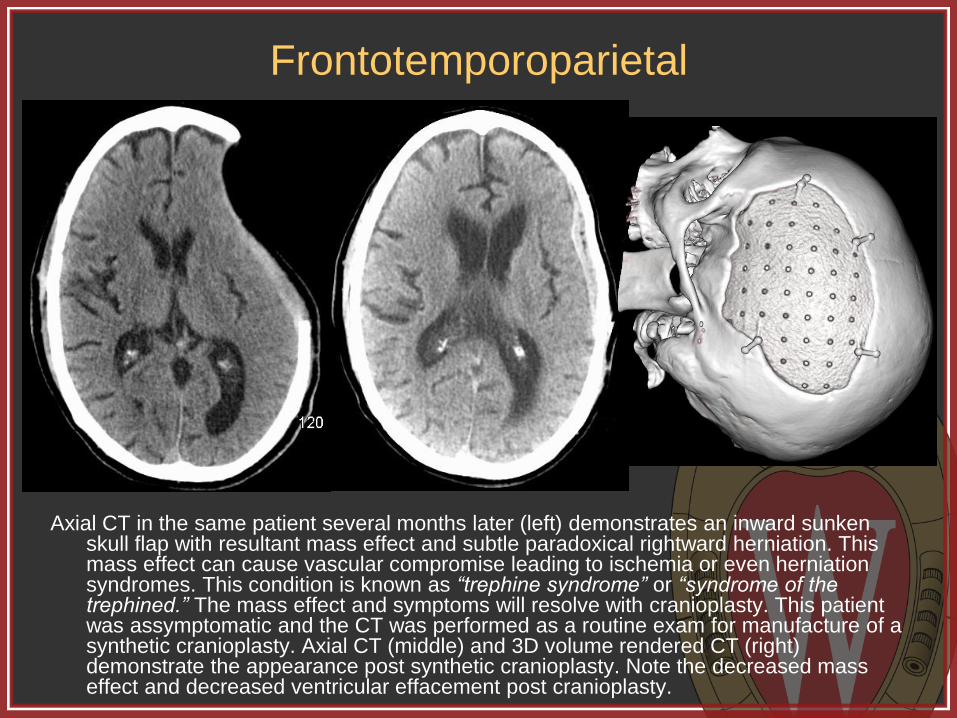
Axial CT in the same patient several months later (left) demonstrates an inward sunken skull flap with resultant mass effect and subtle paradoxical rightward herniation. This mass effect can cause vascular compromise leading to ischemia or even herniation syndromes. This condition is known as “trephine syndrome” or “syndrome of the trephined.” The mass effect and symptoms will resolve with cranioplasty. This patient was assymptomatic and the CT was performed as a routine exam for manufacture of a synthetic cranioplasty. Axial CT (middle) and 3D volume rendered CT (right) demonstrate the appearance post synthetic cranioplasty. Note the decreased mass effect and decreased ventricular effacement post cranioplasty.
Frontosphenotemporal (pterional)
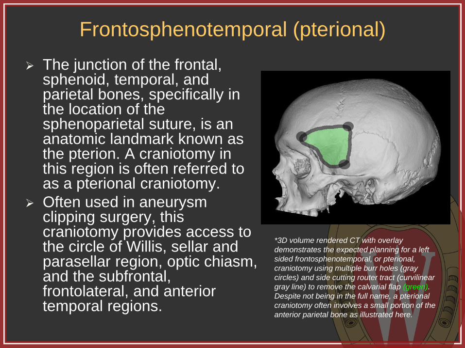
The junction of the frontal, sphenoid, temporal, and parietal bones, specifically in the location of the sphenoparietal suture, is an anatomic landmark known as the pterion. A craniotomy in this region is often referred to as a pterional craniotomy.
Often used in aneurysm clipping surgery, this craniotomy provides access to the circle of Willis, sellar and parasellar region, optic chiasm, and the subfrontal, frontolateral, and anterior temporal regions.
*3D volume rendered CT with overlay
demonstrates the expected planning for a left
sided frontosphenotemporal, or pterional,
craniotomy using multiple burr holes (gray
circles) and side cutting router tract (curvilinear
gray line) to remove the calvarial flap (green).
Despite not being in the full name, a pterional
craniotomy often involves a small portion of the
anterior parietal bone as illustrated here.

Frontosphenotemporal (pterional)
Axial contrast enhanced CT angiogram (top left) demonstrates an aneurysm arising from an early bifurcation of the middle cerebral artery. Post operative axial soft tissue (top middle) and bone window (top right) CT images demonstrate the expected appearance status post pterional craniotomy for aneurysm clipping. Note the metallic clip in the location of the aneurysm. The patient also has a coil mass on the right from a previously coiled aneurysm. 3D volume rendered CT (bottom right) demonstrates the appearance and location of the craniotomy.

Orbitozygomatic
The orbitozygomatic craniotomy is very similar to the pterional craniotomy except, as the name implies, it involves extension in to the superior orbit as well as a small portion of the zygomatic bone.
The OZ craniotomy is used for similar indications and provides similar access as the pterional craniotomy, but secondary to the additional bone removed, provides better access to the inferior margin of the circle of Willis and is often used on more difficult to access aneurysms.
*3D volume rendered CT with overlay
demonstrates the expected planning for a left
sided orbitozygomatic, craniotomy using
multiple burr holes (gray circles) and side
cutting router tract (curvilinear gray line) to
remove the calvarial flap (green). Note the
similarity to the pterional craniotomy but with
extension into the superior orbit and a portion
of the zygomatic bone.

Orbitozygomatic
Axial noncontrast CT (left) demonstrates diffuse subarachnoid hemorrhage throughout the basilar cisterns. Axial (middle) and sagittal (right) reformatted maximum intensity projection (MIP) images from a subsequent CT angiogram demonstrate a small inferior and posterior projecting aneurysm arising from the anterior communicating artery. The patient was taken for operative clipping of the aneurysm. Given the posterior and inferior projection, an orbitozygomatic approach was chosen to allow greater access to and intraoperative visualization of the aneurysm.

Orbitozygomatic
Axial noncontrast CT images in soft tissue (left) and bone (middle) windows demonstrate the expected post operative appearance status post left orbitozygomatic craniotomy for clipping of the anterior communicating artery aneurysm. Note that the cranitomy extends into the left frontal sinus placing the patient at a slightly higher risk for developing infection or cerebrospinal fluid leak. The orbit should be closely scrutinized in all orbitozygomatic craniotomy patients to evaluate for possible orbital injury or hematoma.

Suboccipital Though the craniotomy
involves the occipital bone, it is referred to as suboccipital because it provides access to the posterior fossa, not the occipital lobe.
Can be either midline or lateral and provides access to the cerebellum, 4th ventricle, dorsal pons and medulla, and the pineal region. Far lateral approaches can also provide access to the cerebellopontine angle cistern.
Surgery for posterior fossa decompression typically also involves removing the posterior arch of C1.
*3D volume rendered CT with overlay
demonstrates the expected planning for a
midline suboccipital craniotomy using multiple
burr holes (gray circles) and side cutting router
tract (curvilinear gray line) to remove the
calvarial flap (green).

Suboccipital - Midline
Midline sagittal T1 weighted MRI image (top left) demonstrates downward herniation of peg shaped cerebellar tonsils consistent with Chiari 1 malformation. The patient had chronic headaches and elected to undergo posterior fossa decompression. Post operative axial bone window CT (top middle) demonstrates the removal of the middle portion of the inferior occipital bone and placement of a titanium plate over the osseous defect. 3D volume rendered CT images (top and bottom right) demonstrate the plate position. Also note the absence of the posterior arch of C1, which was operatively removed as is often performed in posterior fossa decompression.

Suboccipital - Lateral
Axial T2 weighted (top left) and post contrast T1 weighted (top
middle) MRI images in a different patient demonstrate a
large, heterogenous mass within the left cerebellar
hemisphere with surrounding vasogenic edema and mass
effect with effacement of the 4th ventricle and compression
of the pons. Post operative axial T2 weighted (top right)
and post contrast T1 weighted (bottom right) demonstrate
the expected appearance status post left lateral
suboccipital craniotomy for resection of what was
confirmed to be a metastatic lesion. Note decreased
compression of the pons.

Suboccipital - Lateral
Axial CT images of the posterior fossa in soft tissue (left) and bone (middle) windows
demonstrate the expected appearance status post left lateral suboccipital craniotomy for
resection of the left cerebellar hemisphere metastatic lesion. Note the presence of a
square titanium cranioplasty molded to the calvarial contour. 3D volume rendered CT
(right) demonstrates the location of the craniotomy and appearance of the titanium plate.

Summary
Imaging plays a key role in the preoperative and
postoperative evaluation of neurosurgical patients, and
neuroradiologists should be facile with the various
approaches utilized in intracranial operations.
This exhibit demonstrated neurosurgical approaches for
operations such as cranial decompression, tumor
resection, and aneurysm clipping, highlighting the most
common neurosurgical approaches, including anatomic
considerations, imaging appearance, and imaging of
several complications.

References Angeli S. Middle fossa approach: indications, technique, and results. Otolaryngol Clin N Am 2012; 45: 417–438
Arriaga M and Lin J. Translabyrinthine approach: indications, techniques, and results. Otolaryngol Clin N Am 2012;
45: 399–415
Barnes B et al. Minimally invasive surgery for intracerebral haemorrhage. Curr Opin Crit Care 2014; 20: 148–152
Ducruet A et al. The surgical management of chronic subdural hematoma. Neurosurg Rev 2012; 35: 155–169
Elhammady M et al. Retrosigmoid approach: indications, techniques, and results. Otolaryngol Clin N Am 2012; 45:
375–397
Flechsenhar J et al. Hemicraniectomy in the management of space-occupying ischemic stroke. Journal of Clinical
Neuroscience 2013; 20: 6–12
Hunter T et al. Medical devices of the head, neck, and spine. RadioGraphics 2004; 24: 257–285
Kilincer C et al. Contralateral subdural effusion after aneurysm surgery and decompressive craniectomy: case report
and review of the literature. Clinical Neurology and Neurosurgery 2005; 107: 412–416
Shah A et al. Materials used in cranioplasty: a history and analysis. Neurosurg Focus 2014; 36 (4): E19
Silk P et al. Surgical approaches to vestibular schwannomas: what the radiologist needs to know. RadioGraphics
2009; 29: 1955–1970
Sinclair A and Scoffings D. Imaging of the post-operative cranium. RadioGraphics 2010; 30: 461–482
Stiver S. Complications of decompressive craniectomy for traumatic brain injury. Neurosurg Focus 2009; 26 (6): E7
Takeuchi S et al. Decompressive hemicraniectomy for spontaneous intracerebral hemorrhage. Neurosurg Focus
2013; 34 (5): E5
Taljanovic M et al. Gallery of medical devices part 2: devices of the head, neck, spine, chest, and abdomen.
RadioGraphics 2005; 25: 1119–1132
Tebo C et al. Evolution of cranial epilepsy surgery complication rates: a 32-year systematic review and meta-analysis.
J Neurosurg 2014; 120: 1415–1427
Zuo P et al. Functional outcome and postoperative complications after the microsurgical removal of large vestibular
schwannomas via the retrosigmoid approach: a meta-analysis. Neurosurg Rev 2014; 37: 15–21