neutron booster feasibility and property investigations
TRANSCRIPT

EUROPEAN COMMISSION D I R E C T O R A T E - G E N E R A L J R C JOINT R E S E A R C H C E N T R E Institute for Transuranium Elements
Date: 05,02.2001
Title
Neutron Booster Feasibility and Property Investigations
Autfior{s) J. Galy
J. Valkó and H. van Dam Interfaculty Reactor Institute
Mekelweg 15. 2629 JB Delft, The Netherlands
Report Nr.: JRC-ITU-TN-2001/03
Classification :
Type of Report: Contract No. 15848-2000-03 F1SC KAR NL
Name Date Signature —><^ ^ ^^J^
reviewed by the autfior
Dr. J . Galy 5.02.2001 ^ ^ ^ " ^
approved by tfie project leader
Dr. J. Magil l 5.02.2001
released by ttie Director
Dr. R. Schenke l 5.02.2001
Legal notice / disclaimer
Neither ihe European Commission nor any person acting on behalf of the
Commission is responsible for the use which might be made of the
mformation contained in this document.
ISO 9001 QUALITY S Y S T E M Reg. Nr. 59429-01
Po<;tfarh 2340 D-76125 Karlsruhe - Germany
ï S h o n e direct line (.49-7247)951-366, switchboard 951-0. Fax: 951-591
Internet: E-mail: [email protected] ; WWW: http://www.jrc.org

Distribution list This report was printed in 20 unnumbered copies.
Copy
Messrs.
R. Scheni el (Director)
J.-F. Babelot (QM Office)
J. Magill (Project co-ordinator)
J. Galy
Mrs. Martellenghi (Registration)
J. Richter (Archives)
H. Van Dam
ITU Ix
ITU Ix
ITU 4x ITU Ix
ITU 2x
ITU Ix
IRI lOx

Neutron Booster Feasibility and Property Investigations
J. Galy
J. Valkó and H. van Dam Interfaculty Reactor Institute
Mekelweg 15, 2629 JB Delft, The Netherlands
under Contract No. 15848-2000-03 FISC K A R N L

Summary:
One can design a critical system with fissile material in the form of a thin layer on the inner surface of a cylindrical neutron moderator such as graphite or beryllium. This an-angement can be used for the design of a neutron booster assembly (called neutron booster) comprising of a slightly subcritical arrangement of fissile material with a primary neutron source. The thickness o f the required fissile layer depends on the type of fissile material, its concentration in the layer and on the geometrical arrangement.
Some potential applications o f thin fissile layers in nuclear technology can be foreseen,
such as:
1) Booster spallation sources. In this application a thin layer o f fissile material surrounds the spallation source. Consequence of this is that less powerflil accelerators may be required in accelerator driven systems.
2) Neutron amplifier for medical applications. A cylindrical shell unit using a thin fissile layer can be conceived whereby an enhancement of an order o f magnitude in the neutron flux can be produced for specified applicafions.
3) Dedicated fast islands in a reactor core. This idea has been investigated at the Institute for Transuranium Elements, Karisruhe, for burning minor actinides in a special zone inside thermal reactors. In these zones, the neutron spectrum is fast and is produced through the interaction o f thermal neutrons with the thin fissile layer.
Systematic investigations o f the properties of thin layer systems, based on criticality and source multiplication calculations have been performed with the help of neutron transport codes. In the present report, we present the results of these neutronic property studies.

i
ii

Table of contents
1. INTRODUCTION 1
1.1 Description of tlie booster concept 1
1.2 Potential applications of thin layers in nuclear technology 2
1.3 Computer code system 3
1.4 Strategy of the investigations 5
2. 1 -DIMENSIONAL CALCULATIONS 5
2.1 Critical thickness investigations 5
2.1.1 Spherical geometry 5
2.1.2 Cylindrical geometry 7
2.1.2.1 Influence of the graphite thickness on the reactivity 7
2.1.2.2 Criticality calculations 8
2.2 Source multiplication investigation in ID 10
3. 2D INVESTIGATIONS WITH DORT 11
3.1 Number of broad groups 11
3.2 Criticality 12
3.3 Source multiplication 13
3.3.1 Leakage 13
3.3.2 Influence of the kejf. 16
3.3.3 Flux inside material region 17
3.3.4 Flux through the system 18
3.3.5 Initial burnup 19
3.4 Beryllium reflector investigations 20
3.5 Double layer system/Muiti-amplification 23
3.6 New configuration (top and bottom stopper) 24
4. MCNP CALCULATIONS 25
4.1 Verification of the DORT results 25
ii i

4.2 Remarks about the use of different libraries 26
CONCLUSIONS AND RECOMMENDATIONS 28
REFERENCES 30
LIST OF TABLES 32
LIST OF FIGURES 34
APPENDIX A: SYSTEMATIC INVESTIGATIONS OF THE TECHNICAL
PARAMETERS 35
APPENDIX B: BUCKLING CORRECTION IN XSDRNPM 38
APPENDIX C: THE FINE AND BROAD ENERGY GROUP STRUCTURE 39
APPENDIX D: CROSS-SECTIONS 44
APPENDIX E: SAMPLE INPUT OF DORT SOURCE CALCULATION 46
iv
1. Introduction
The first reference to thin layers of fissile material in the design of nuclear reactors was by Chapline [1] in 1988. In this work, the author proposed very thin (< 5 ^m) fibers of carbon coated with fissile material and placed inside a magnetic field. The novelty of the proposal belongs to the fact that the fission products can escape fi-om the fibers (reactor core) and be guided out. One application of this interesting concept was the design of a propulsion unit for space exploration [1,2]. Chapline [1] and Ronen [3,4,5] suggested the use ^''^"Am as a nuclear fiiel for such space reactors or for small core reactors. The advantage of '* '"Am as a nuclear fuel derived fi-om the fact that ' '"Am has the highest thermal fission cross-section of all known isotopes. The amount of "Am required to obtain a given koo is significantly less than for other fissile isotopes such as ^ Pu and ^^^U, as demonstrated by Ronen et al. [3]. The idea of spaceship reactor based on thin layers has been recently reconsidered by Rubbia [6], who has presented the possibility of using thin layer of fissile material in an Hohlraum geometry as a propulsion engine concept for space exploration. These ideas have been fiirthér investigated at the ITU [7, 8, 9, 10], where it has been shown that through the use of thin layers (10 [im (in the case of ^''^'"Am) or in the range of a few mm in the case of uranium or plutonium isotopes) one can design critical or near critical systems in which the absolute amount of material is small and the system has favorable heat transfer properties [7, 8].
Based on these considerations, a collaboration between the ITU and the Interfaculty Reactor Institute (IRI), Delft, the Netherlands has been established for a "Feasibility study on aNeutron Booster Concept" under the study contract No. 15848-2000-03 Fl SC KAR NL. The group at Delft has a unique expertise in the area of nuclear reactors and associated research in this field, and has an extensive neutron computer code collection required for such kinds of investigations.
The aim of this joint study was a) to investigate the feasibility of the Neutron Booster concept and, b) to consider the potential applications of this concept such as to develop fast zones in thermal reactors, neutron amplifier for medical applications etc.
The present report will discuss the first part of the investigations: the feasibility and the properties of the Neutron Booster concept. For basic reading and understanding of the reactor physics concept, references to classic work and textbook is given in ref [*].
1.1 Description of the booster concept
A critical or near critical system based on the use of thin layer actinide films is shown schematically in Fig. 1. The fissile material constitutes a thin layer on the inner surface of a hollow cylinder, made of neutron moderator material such as graphite or beryllium. The thickness of the layer is to be determined and is one of the main purposes of the present investigations. This thickness depends mainly upon the type of the fissile nuclide, its concentration in this layer and the global geometry of the system.
I

Inside the Hohlraum, one can insert a primary neutron source depending on the application, to the case of the spallation booster discussed to the next section, this could be a spallation source.
moderator
Figure 1. Critical or near critical system based on a Hohlraum, a thin actinide layer, a moderator and a likely inner neutron source.
1.2 Potential applications of thin layers in nuclear technology
Some interesting applications can be foreseen from the previous studies of the properties of thin layer of fissile material:
1. Boosted Spallation Sources, to this application, a thin layer of fissile material surrounds the spallation source. Consequence of this is that considerably less powerfiil accelerators may be required in accelerator driven systems (ADS), tostead of using, for example, a 1 GeV proton beam (leading to a production of about 30 neutrons per proton), one requires only around 150 MeV protons (typically of medical cyclotrons, and leading to a production of about 1-3 neutrons per proton). This has important consequences not only on the economics of ADS but also on the non-proliferation aspects (i.e. one does not need very powerful accelerators).
2

2. Fast Island Concept for Minor Actinide Incineration. At present, preliminary calculations have been made at ITU on the idea of burning Minor Actinides in special zones inside thermal reactors. In these zones, the neutron spectrum is fast and is produced through the interaction of thermal neutrons with the thin fissile layer.
3. Neutron Amplifier for medical applications. A cylindrical shell unit using a thin layer can be conceived whereby an enhancement of an order of magnitude in the neutron flux can be produced for specific medical applications. This unit can be "folded". To switch the unit on, the unit is expanded whereby the gain of the "amplifier" increases.
Patent applications [8,9], which cover points 1, 2 and 3 above, have been submitted by ITU.
1.3 Computer code system
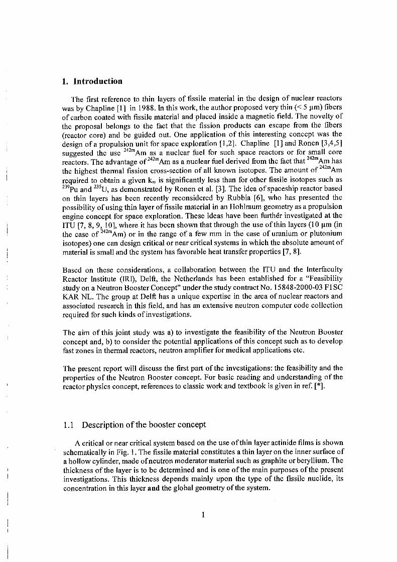
Most of the calculations discussed in this report have been performed by the INAS (IRI-NJOY-AMPX-SCALE) code system, at IRI. Fig. 1 shows the part of the INAS code system that was used in our studies of the neutron booster properties.
For the deterministic codes we have used nuclear libraries based on JEF2.2. Those data were processed with special codes to make an AMPX-master library with 172-neutron energy groups. For the Monte Carlo (MCNP4c) calculations we have used the data libraries based on both ENDF/B V I and JEF2.2. Remarks about this topic are discussed in the relevant section of this report.
The discrete-ordinate code XSDRNPM-S (ID, neutron transport code) [11] was used to calculate the properties of a spherical system and for the 1-dimensional cylindrical calculations as a first approximation of the system. The fiinction of XSDRNPM is, four our purpose, twofold:
1) To perform a 1-D discrete-ordinates calculation in slab, cylindrical, or spherical geometry (optionally, a 1-D diffusion theory or infinite medium B„ calculation can be made).
2) Use the fluxes determined from its spectral calculation to collapse input cross sections. The produced zone-weighted cross sections are required for the DORT (2-D, neutron transport code) calculations described further on.
A great deal of flexibility is allowed in describing a problem for XSDRNPM. The number of spatial intervals, the number of energy groups, the number of nuclides, the quadrature order, the order of fits to the angular variation in basic cross sections are all arbitrary chosen by the user and are limited only by computer resources. The flux calculation can be performed according to several options, including fixed source calculations, k-calculations, and dimension search calculations.
3
E N D F / B - J E F
Monte Cailo (Probabilistic method)
AMPX M A S n - K
W O R K ;
\ s n k N i » M - s
Neutron transport ID Discrete ordinates
W E I G H T y Neutron transport 2D
Discrete ordinates
Figure 2. Part of the INAS code system that was used for the analysis of the neutron booster investigations.
The transport 2-dimensional discrete ordinate DORT [12] code has been used for both criticality and neutron multiplication calculation of the system based on the Sn method^ The code is mainly dedicated to solve problems dealing with the calculaüon of radiation resulting trom a given extraneous source, i.e. "fixed-source" problems. If such a system has tissile material and is subcritical, the multiplication factor can be calculated. The code also has the keff calculation capability and various types of searches (dimension search calculations). The directional quadrature set can be chosen from an arbitrary
' The sn meüiod is also called discrete ordinates method. It is based on a discretization of the duection variable in the
approximation.
4

number of input sets, and both ID and 2D geometries can be treated. The DORT output file contains both distributed flux moments and boundary directional fluxes.
Additional calculations have been performed using MCNP4c. The major feature of using MCNP4c code [13] is that it uses poinfless continuous energy cross secfion data, and that it "solves" the transport problem by simulating particles history rather than by solving the transport equation. On the other hand, Monte Cario code has the disadvantages of stafistical scatter in the results and its large appetite for computer time.
1.4 Strategy of the investigations
The neutron booster/mulfilayer geometry is not a typical muhiplying geometry in terms of reactor physics. This fact implies that a careful study of all technical parameters in the input file of the used codes is required. Furthermore, particular care has been given to the convergence, which has been turned out to be particularly slow with the unusual geometry of the neutron booster system.
The investigations of the properties of the system have been separated into two studies. The first one consists in the investigation of the criticality with systematic studies of the dimensions of the materials and their influence on the reactivity of the system. These investigations are based on the geometry suggested by the authors of those papers [7,8], which formed a starting point for the present investigation. Once the geometry of critical or subcritical systems has been investigated, we have been interested in the multiplying properties of such systems by inserting a neutron source and looking at the output such as flux or leakage.
The following chapters summarize the results from these studies.
2. 1-Dimensional Calculations
2.1 Critical thickness investigations
2.1.1 Spherical geometry
The spherical shape is a basic geometry, which allows a good understanding of the studied systems and gives trends of its properties.
Criticality search has been performed for spherical geometry with the thickness of the graphite layer equal to 70 cm. The results of these investigations are collected in the following tables:
5

0 Thickness
ketf Critical mass 0 radius Thickness Critical mass
radius (cm)
(cm) ketf (g) (cm) (cm) keff
(g)
10 1.2722 0.99407 30215.31 10 0.5111 1.00006 2780.384
20 0.533 0.997844 50635.94 20 0.1144 1 2489.344
40 0.1335 1.00517 50730.94 40 0.0027 1.00674 235.008
60 0.0418 1.00629 35739.66 60 0.0006 0.9901 117.504
100 0.004 0.990584 9500.176 100 - - -
Table 1. Spherical critical thickness of "'Am and U layers (O radius = Hohlraum radius).
Using spherical geometry , one observes that the thickness of fissile material required to make the system critical decreases considerably when the inner diameter increases.
We can see here an important and fundamental fact, that with a small Hohlraum, we have a "fast" system, i.e. the chain reaction is based on fission by epithermal and fast neutrons. With a larger Hohlraum the probability of moderation and retuming to the fission layer becomes such that the chain reaction is accomplished by thermal neutrons, which is indicated by a drastic decrease in the critical layer thickness.
One can insert a 5 cm radius Pb sphere inside the Hohlraum and see how the kefr is affected.
0 radius Thickness keff
0 radius Thickness keff (cm) (cm) keff (cm) (cm) keff
10 1.2862 1 10 0.5146 1.00001
20 0.5476 0.999997 20 0.1154 r.00016
40 0.1499 0.999994 40 0.0032 1.0032
60 0.0431 1.0014 60 0.00065 0.9996
100 0.011 1.00032 100 - -
Table 2. Spherical critical thickness of ™ Am and U layers with an inner Pb sphere of 5 cm radius.
As expected, the introduction of a lead sphere inside the Hohlraum has just a small influence on the reactivity of the system. Indeed, lead has a small absorption cross-section.
6

2.1.2 Cylindrical geometry
In this section, the cylindrical calculations performed with the XSDRNPM 1-dimensional discrete ordinate code are described.
XSDRRPM allows 'l5uckling approximation", which means, in our case, that the transport equation is solved by a quite general method in two dimensions, RZ, with a certain assumption on the behavior along the third dimension, Z. The assumption for the Z direction is that the system is homogeneous along the length z=0 to z=H. Then, with separation of variables, the solution along z is written in terms of eigenflinctions. The fundamental eigeniunction that is nonzero in the whole range is, in this case, a sin(Bz)
function where B = - ^ i f flux=0 is required at both ends. B is called "buckling".
In the following XSDRNPM results, when we speak of height, we refer to the first transverse dimension used in a buckling correction to calculate leakage normal to the principal calculation direction (the DY parameter in the input file). This approximation is crude, but gives trends of the properties of the system.
2.1.2.1 Muence pf.the_grapMt
A systematic investigation of the influence of the thickness of the reflector on the criticality of the system has been performed in order to find the optimum thickness of graphite required by the systems.
In the following calculations, we have used a lead rod with a diameter of 20 cm, the inner diameter of the Hohlraum to 30 cm and the fissile layer is made of ^^^U of 0.06 cm thickness.
Infinite length Length = 200 cm Length =Outer diameter
Thickness C*(cm) keff
Thickness C* (cm) kefr
Thickness C* (cm) keff
10 0.126318 10 0.10597 10 0.0636132 20 0.404602 20 0.325264 20 0.1965 30 0.675063 30 0.540772 30 0.38757 60 1.05009 60 0.8179 60 0.7374 100 1.17852 100 0.889379 100 0.990004 120 1.19984 120 0.8975474 120 1.04491 150 1.21512 150 0.901937 150 1.09778
When the Graphite thickness is greater or equal to 100 cm, we have used 100 mesh points for this zone in the calculations.
7

200 1.22486 | 200 0-903329 | 200 1-14682_
Table 3. Reflector thickness influence on the reactivity of the neutron booster with a thin layer of ^"U
It can be seen from table 3 that for graphite thickness above Im, keff does not increase significantly. This is expected for physical reasons, because the thermal neutron diffusion length in graphite is about 50 cm.
2.1.2.2 Crjticality.calmlMo.ns
In the following, calculations have been performed in order to find the thickness of '^ 'U and '"""Am layers to make the system critical for various cylindrical geometries. '"'•"Am has been chosen as a likely fissile material as a layer because its thermal fission cross-section is about an order of magnitude higher than that of U. .
In all the critical thickness calculations of this section, the thickness of the graphite
reflector is equal to 70 cm.
235u 242m
Hohlraum diameter
(cm)
Critical thickness
(cm) keff
Critical thickness
(cm) keff
0 i2.l l 0.99654 1.44 0.99998
20 0.21 1.00034 0.008 0.998972
40 0.05 1.00017 7.00E-04 0.997261
60 0.0133 0.998855 - -
80 0.0099 1.00005 - -
120 0.0056 0.99831 - -
200 0.004 1.00052
Table 4. Layer thickness of " ' U and ''""Am required for criticality for various infinite length cylinder diameters.
Here again, one can notice that with a larger Hohlraum the probability of modemtion and retuming to the fission layer becomes such that the chain reaction is accomplished by thermal neutrons and one goes from a fast system to a thermal system, leading to a drastic decrease of the critical layer thickness.
8

235 U '"'•"Am
Hohlraum Critical Critical
diameter thickness keff thickness keff
(cm) (cm) (cm)
0 5.817 0.999999 4.1573 0.999999
20 1.4306 0.999999 0.5995 1
40 0.7224 1.000001 0.1966 1.00001
60 0.4896 1 0.0873 0.999997
80 0.3908 1 0.0503 0.999914
120 0.3411 0.999997 0.0349 0.999967
200 0.446 0.999998 0.071 1.00017
Table 5. Layer thickness of "^U and " ""Am required for criticality for various cylinder diameters. The calculations have been performed using the buckling correction with a cylmder length equals to 200 cm.
Unfortunately, results of the sphere and the infinite cylinder cannot be directly compared. The two geometries are, indeed, basically different: the curvature of the cylinder is zero along the axis, in the other directions it varies to a maximum that is equal to the curvature of the sphere (if their diameters are the same).
235u '"""Am
Hohlraum diameter
(cm)
Critical thickness
(cm) keff
Critical thickness
(cm) keff
0 2.6903 0.999967 1.66 0.999968
20 0.541 1 0.0947 1.00167
40 0.3003 0.999814 0.0244 0.99745
60 0.23 0.999988 0.0096 1.00144
80 0.2079 0.999973 0.0066 0.997759
120 0.1902 0.999958 0.0044 1.00178
200 0.19 1 0.004 0.99887
Table 6. Layer thickness of and '' "'Am required for criticality for various cylinder diameters. The calculations have been performed using the buckling correction with a cylinder length equals to the outer
diameter of the system.
From tables 4-6, one can notice that for spherical and infinite cylinder geometries, one can use thin layers of fissile material. On the other hand, when one goes to finite cylinder geometry, much thicker layers of fissile material are required to make the systems critical. This is explained by the extreme influence of axial leakage in case of large Hohlraum; on the other hand, in case of a small Hohlraum we have a low neutron return
9

probability for geometrical reasons and the fact that the neutron migration length i graphite is rather large before the neutron is thermalized.
2.2 Source multiplication investigation in I D
As a first approach a fission spectrum source has been used as neutron primary source. In XSDNRPM-S the source can be defined as a boundary source or a volumetric one. To be closer to the likely application (such as e.g. a spallation source), the volumetric source option has been chosen. As a first approximation of what it should be, the source is homogeneous in the whole volume of the Pb rod .
The following multiplication calculations have been performed in pure ID i.e. without buckling correction (infinite cylinder).
Leakage
Thickness C (cm) Thickness U'^^ (cm) keff (per unit source)
70 0.1576 0.950043 8.4334
40 0.4275 0.949997 9.8649
20 0.9976 0.95 8.6243
Thickness C (cm) Thickness Am'""" (cm) keff
Leakage (per unit source)
70 0.0024 0.95977 6.84473
40 0.0677 0.95 12.1336
20 0.3953 0.95 9.98547
Table 7a and 7b. Thickness of'"U and ''""Am layer required for kef O.95 in the system and corresponding leakage when a volumetric fission source is inserted.
The leakage value given in table 7a and 7b corresponds to the net number of neutrons appearing on the outside surface of the system per one neutron source. For a system with keff = 0.95, one is expecting an initial source multiplication about 20. Obviously, absorption occurs in the system leading to an effective multiplication factor of about 9 neutrons per source neutron.
' The external source is homogeneous in the lead; in actual case the source will be concentrated at half height of the cylinder which will lead to decrease axial leakage a bit.
10

3. 2D investigations with DORT
3.1 Number of broad groups
The 2-dimensional-transport code DORT uses the energy multi-group approach in solving the neutron transport equation. It was then necessary to choose an optimal number of broad groups both giving accurate results and saving CPU time m order to find out the accuracy of the results from DORT w th a broad ener^ group calculation, we have used as benchmark a result from XSDRPM using a layer of U and
T o t r f u r e ' ï h a ^ the^codes give coherent results, the DORT calculations have been performed using the ID option, which corresponds to an infinite ^^^^^er geome ly. Additional calculations have been performed using 2D geomefry and reflecting the top and the bottom of the cylinder, and similar results have been found. , Q . . . I We started with a typical 4-group structure, with boundary energy equal to 1.96 10 1 23*10' 9 19 7 05*10- and lO ' eV respectively. Then we have divided these four groups equally in order to get 16, 41 and 172 group-sfructures. This latest one corresponds to the fine group structure ofthe AMPX master library. Table 8 gives the calculated keirusing the different group structures (and corresponding weighted library) on the given geometry initially calculated with XSDRNPM:
number of keff
groups keff
4 1.02949
16 0.985577
41 0.954377
172 0.944816
Table 8. Influence ofthe broad group structure on the k,ff calculations for the booster geometry.
One can notice that the 4-group structure, which is accurate enough in most ofthe reactor calculations, is not sufficient for the neutron booster peculiar geometry.
Following the results of those energy group calculations, the use of 41 groups has been found to be optimal for the rest of our investigations.
Complete description ofthe 41 energy groups used in the following calculations is given
in Appendix C.
11

3.2 Criticality
M the following calculations we have inserted inside the Hohlraum a Pb rod with a radius of 5 cm This rod is supposed to represent the likely primary neutron source n the Afferent applications. The dimension of it is based on a likely spallation target descrintion Fl 31 ( 0 7 cm), even if our representation is a crude approximation ot it. ?heTelght of i e system has been arbitrary chosen to be equal to 1 m, m respect to a "real design".
hi the first step, we have looked for the thickness ofthe Am and U layer required to make the system critical varying the Hohlraum radius and the graphite thickness.
3.0 •
2.5
2.0
tn $ 1.5^
O
1.04
0.5 H
Ht-C10 C20 C50 070
* C100
.235
M2m
3.0
^2.5
- T — , — r . I ' I — T -10 20 30 40 50
1 1 1 1 1 1 1 ' I ' T-10 20 30 40 50
Hohlraum inner radius (cm)
2.0
H . 5
1.0
0.5
Figure 3 Required thickness of^'U and '^-Am to obtain ke«=l with 2D code DORT. The ^f^f^' system equafs to 100 cm and the Pb rod diameter equals to 10 cm. Cx = x cm graphite as a radial reflector.
In a second step, we looked at the same systems, but looking for a keir - 0.95, which is a
subcritical value reasonable value for practical purposes.
12

2.6-,
2.4¬
2.2
2,0
1.8
1.6
1.4 H
1.2
1.0
0.8¬
0.6¬
0.4
0,2 10
242ni
30 40 50
Inner radius (cm)
.235
10 20 30 40
inner radius (cm)
—r 50
2,6
2,4
2.2
2,0
1,8
1.6
H , 4
1.2
1,0
0.8
1-0,6
0,4
0,2
Figure 4 Required thielcness o f ^ U and ^^Am to obtain ke^O.95 with 2D code DORT. The height ofthe ' system equals to 100 cm and the Pb rod diameter equals to 10 cm.
3.3 Source multiplication
In the previous sections, we have made systematic investigations of the critical thickness ofthe fissile material in appropriate geometries. We then want to study the multiplying properties ofthe defmed systems when we insert a neutron source, ht our investigations, we have considered a fission spectrum neutron ««"^^^ « properties ofthe neutron booster. Further calculations may be performed with difierent neutron spectrum source, such as e.g. a spallation neutron spectrum.
3.3. i Leakage
We have then introduced a fission neutron spectrum source in the previous optimized geometries with keff = 0.95. The results of those studies are summarized m Fig. 5. The leakage corresponds to the net number of neutrons escapmg the system.
13

12
10
O tn
=5 0 C i_ 0) Q-0) O)
(0 0
,235
.242m Total leak U
Total leak Am"
i l Side leak U^''
- • - - S i d e leak A m ' ' " "
20 40 60 80 100
Graphi te Th ickness (cm)
Figure 5. Neutron leakage per neutron source for systems with a keH-0.95.
One can notice that an increase ofthe graphite thickness leads to a bigger leakage fi-om
the open top and bottom sides ofthe system.
As shown in the figures, '"""Am presents better multiplication properties than the '^ 'U as a fissile material in the layer. In the following, we have concentrated our calculations on '"'""Am as fissile material.
Fig 6 shows clearly the gradual transition fi-om a fast to a more thermal system when increasing the thickness of the reflector (and then increasing the probability of moderation and retuming to the fission layer ofthe neutrons).
14

Figure 6. Leakage investigation with DORT for various cylindrical geometries using '" ""Am layer.
16000
12000
8000
4000
- tot leakage - rgt netflow
Pb Radius = 5cm Inner radius = 10 cm C ttiickness = 50 cm Am"* ' thickness = 1.005 cm Height = 100 cm
I 1!
i i i iyu^ IHLIH i i i i M I i i i i i l "IIUJH IIIIMJI iiiiiMH I I —a— tot leakage
rgt netflow
Pb Radius = 5cm Inner radius = 10 cm C thickness = 20 cm Am'''"" thickness = 0,5952 cm A
A Height = 100 cm
/ ./ /
\ 1 1 i . . . . - 1 . . . . . J i i i i i r f m i l d 1
. . J . . • I R I
16000
5 •3
4000
0 10' 10-= 10-' 10° 10' i t f 10' 10" 10' 10= 10' 10'
Energy (eV)
10" 10"'
Energy (eV)
10000
••S 8000
3 B ° c6000
-9 4000
2000
—Ar—tot leakage — r g t netflow
Pb Radius = 5cm Inner radius = 10 cm C thickness = 50 cm
Height = 100 cm thickness = 0.2578 cm
- i - A. :
"1 "»n '""M '"" ' -A— tot leakage -m— rgt netflow
Pb Radius = 5cm Inner radius = 10 cm C thickness = 70 cm A m " ^ thickness = 0,2244 cm Height = 100 cm
12000
10000
8000
l \
6000 3 ^
2000
10"" lO-' 10' 10-' 10» 10' l t f i t f 10* It f 10' 10' 10'
Energy (eV)
10- 10' 10' 10-' ICf 10' 10= 10= 10' 10' l t f 10' irf
Energy (eV)
12000
10000
3 1 t i
< ^ 6000
4000
2000
^ tot leakage rgt netflow
Pb Radius = Scm Inner radius = 10 cm C thickness = 100 cm Am242m thickness = 0.2147 cm Height = 100 cm
10- 10' 10' 10° 10' 10' 10' 10* 10' 10' 10' 10'
Energy (eV)
15

3.3.2 Influence of the keff
It is interesting to look at the variations of the leakage when we vary ketf m the system For this purpose, we have used two values ofthe keff corresponding to one case where the system is far subcritical (kefpO.9) and another where the system is reallj^ close to criticality (kes=0.98). We have then looked for the required thickness ofthe Am layer corresponding to these cases and looked at the leakage results when we insert a fission spectrum neutron source into those systems.
eff
• Total leakage s Side leakage
Graphite thickness = 10 cm
« Total leakage B Side
Graphite thickness = 50 cm
« Total leakage • Side leakage
Graphite thickness = 20 cm
Total leakage Side leakage
Graphite thickness = 100 cm
eff
Figure 7. Influence ofthe kes on the leakage for various cylindrical geometries using "Am layer.
On can notice the radical changes in the leakage with kefr. It is quite interesting to notice from those graphs that the effective neutron multiplication (leakage) is about half of the total multiplication, so about 50% ofthe neutrons are absorbed in the reflector and about 50% leak out, due to the present geometry.
16

3.3.3 Flux inside material region
It is interesting to look at the energy distribution of the flux inside the diiïerent
materials constituting the system.
50
40
3 30
< X 3
20
10
-m— Pb (R = 5 cm) Hohlraum (R = 10 cm)
Flux in the materials
1 I H I I I 1 | I I I I I H I I I """I ' ' " " ' I • " • " " ! '
. i , ^ - A m " " " (Thickness = 0.2244 cm) ^ - Graphite (Thickness = 70 cm)
/
,1 • •' ' I " "
10- 10- 10- 10- 10° 10 10 10' 10' 10' lo'' 10' 10
Energy (eV)
Figure 8. Fluxes calculated inside the different materials ofthe booster.
A expected, fast neutrons are present in the source (Pb), the Hohlraum and the fissile layer. Thermal neutrons are predominately present in the moderator (graphite). This graph shows clearly that we have a fast system.
17

3.3.4 Flux through the system
To understand how the neutrons are distributed in the system, one can have a look at
the flux vs the radial axis ofthe system. • ^. A For a better readability ofthe graph, we have condensed the flux of 41 groups mto 4
groups as defined in section 3.1.
Pb Graphite
3.57x10
3.06x10'
2.55x10"
^ " 2.04x10'
q
1.53x10'
1.02x10'
5.09x10'
0.00
^ 2-55X
1.02X'
5-09*
i
0
-m— Group 1
• — Group 2
A^- Group 3
Group 4
, . A - A - . *
Pb radius = 5 cm Hohlraum radius = 10 cm Am""" thickness = 0.2244 cm Graphite thickness = 70 cm
20 40 60
Radial size (cm)
80
Figure 9. Fluxes versus system radius for four energy group calculation.
From Figure 9, we see that groups 2 and 3 dominate in the chain reaction. One can notice that the fast neutrons, which do not escape fi-om the top and bottom are quickly slowed down in the graphite. A maximum in the flux of fast neutrons can be found m the reflector layer (in our example at about 25 cm), this could be of fiiither use.
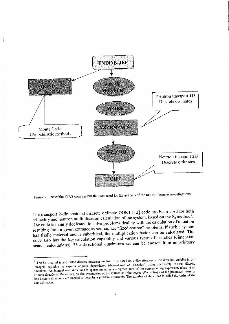
The most interesting remark comes when one has a look at Ae ^ssile material zo ^ ^ our example case between 10 cm and 10.2244 cm) as shown m Figure 10. We can notice that there is no thermal flux in the first 8O0/0 ofthe layer and * - ' ^ % b ^ ^ g ; ™ 2 4 ? I flux appears when close to the reflector. This is easily explained by the fact that Am has a high thermal fission cross-section (about lO'* bams) in comparison to the fast cross-
18
section (about 10 bams). Indeed, most ofthe thermal neutrons are immediately absorbed whin they penetrate the Am layer, and the presence of a high tlux on the right side corresponds to the neutrons slowed down in the graphite. i , „ These results (combined with the previous calculations) show us that without the leakage of most of the fast neutrons ti-om the top and bottom ofthe system, the fissile layer would be really thin (see the spherical calculations).
2.55x10
10.0 10.1
Radial size (cm)
10.2
Figure 10. Flux inside the Am layer for the thermal and epithermal groups'.
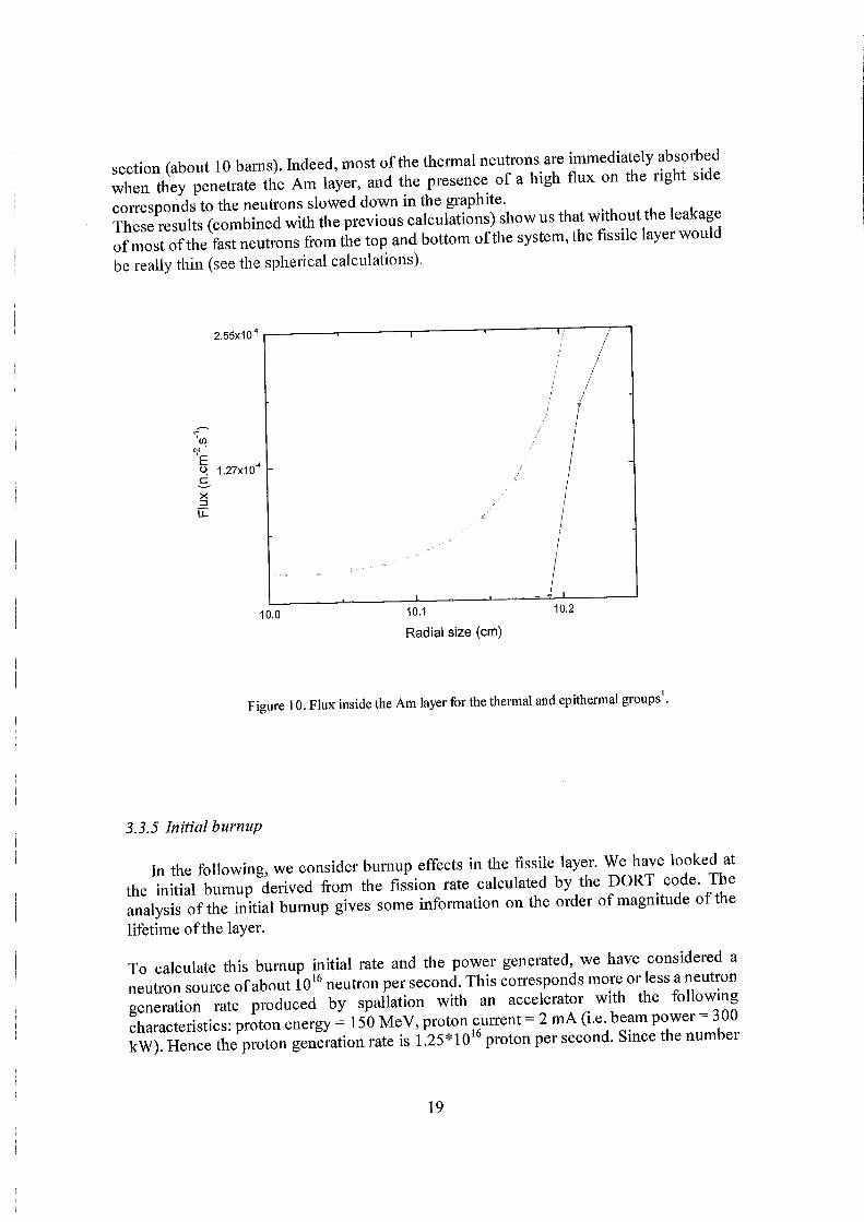
3.3.5 Initial burnup
In the following, we consider burnup effects in the fissile layer. We have looked at the initial burnup derived fi-om the fission rate calculated by the DORT code. The analysis ofthe initial burnup gives some information on the order of magnitude ot the lifetime ofthe layer.
To calculate this burnup initial rate and the power generated, we have considered a neutron source of about lO'^ neutron per second. This corresponds more or less a neutron generation rate produced by spallation with an accelerator with the following characteristics: proton energy = 150 MeV, proton current = 2 mA (i.e beam power - 300 kW) Hence the proton generation rate is 1.25*10 ' proton per second. Since the number
19

of neutrons oer proton is approximately unity at 150 MeV, the neutron generation rate is
also 1.25.10' per second.
0.000
A 2.3x10'
A 1.9x10''
-0
Q A 1.4x10' I TO — Ï
9.3x10' ^
H 4.6x10
20 40 60 80 100
Subcritical mass (kg) of '"'""Am for = 0.95
Figure 11. Initial burn-up vs. subcritical mass ofthe layer of'^'"Am for various cylmdrical systems.
The figure 11 shows the initial burnup which can be derived fi-om the calculated fissioii rate of the multiplying system. These results reveal that with the actual calculated thickness of the layer one can expect the layer to have a long efi^ective operational lifetime (actually, the relative burnup is so small because of the large thickness of he fissile layer). Of course, this is just initial burnup and, as explained previously, a detailed study is needed in order to know the build up of fission products/actinides and its influence on the reactivity of the system and etc.
3.4 Beryllium reflector investigations
Until now, we have been considering only graphite as a likely reflector. Beryllium
presents better moderation properties than the graphite's ones and it is occasionally used
in reactor design.
20

Thanks to the shorter moderation distance one needs considerably less Be m order obtain the same behavior than graphite. Table 9 shows the amount of Be required obtain keff = 0.95 with previous graphite based systems:
Granhite reflector Beryllium reflector
Thickness (cm)
Total leakage (per source unit)
Side leakage (per source unit)
Thickness (cm)
Total leakage (per source
unit)
Side leakage (per source
unit)
10 11.071 9.28 4.22 9.283 4.22
20 11.258 8.316 7.21 11.627 9.937
50 10.946 4.702 11.60 11.982 9.666
70 10.599 2.822 12.39 11.951 9.544
100 10.207 1.197 12.51 11.983 9.533
Table 9 Required Be thickness to reach ke( 0.95 with the required thickness of k fl=0 95 for various graphite thickness, with Pb rod radius equals to 5 cm and Hohlraum radius equals 10
cm. The length ofthe system is 1 m. Comparison of the leakage for the C/Be systems.
I f one has a look at the leakage, one can notice that because of the thinner required layer of reflector much less neutrons "escape" from the top and bottom due to the new geometry. On the other hand, the shape ofthe flux is quite similar (one can see again the gradual transition from a fast system to a more thermal one).
From table 9 one can note that beryllium is a good moderator because the slowing down distance is smaller than in graphite, and a good multiplication of almost 12 is obtained with a much smaller radius ofthe system. The leakage is now mainly side leakage which is advantageous for the application of such a system.
21

Figure 12. Leakage investigation with DORT for various cylindrical geometries using """"Am layer with Be as reflector.
A- tot leakage • rgt netflow
"m '""1 "'"H '
12000
5- g-8000
Pb radius = 5 cm Inner radius = 10 cm '°'"Am tlilckness = 1.005 cm
Be thickness = 4.22 cm Height = 100 cm
•-• 1 •
10" 10-" 10' 10' 10° 10' 10' 10' 10" 10' 10°
Energy (eV)
- I I — tot leakage rgt netflow
Pb radius = 5 cm Inner radius =10 cm ''"^Am thickness = 0.5952 cm Be thickness = 7.21 cm Height = 100 cm
8000 53 = •3 -S
10' 10" 10" 10^ 10' 10' 10° 10' 10' 10' 10" 10' 10' 10' 10'
Energy (eV)
- A — tot leakage - •— rgt netflow
8000
Ö m S ^ 4000
Pb radius = 5 cm Inner radius = 10 cm """Am thickness = 0.2578 cm Be thickness = 11.6 cm Height = 100 cm
-tot leakage - rgt netflow
Pb radius = 5 cm Inner radius = 10 cm '"""Am thickness = 0.2244 cm Be thickness = 12.29 cm Height = 100 cm
8000
1^ <D
10" 10-° 10' 10' 10° 10' 10' 10' 10" 10' 10' 10' 10' 10" 10-' 10' 10" 10° 10' 10' 10' 10" 10' 10° 10' 10°
Energy (eV) Energy (eV)
\ 4000
- tot leakage rgt netflow
Pb radius = 5 cm Inner radius = 10 cm '"'"Am thickness = 0.2147 cm Be thickness = 12.51 cm Height = 100 cm
10" lo-' 10' to" 10° 10' 10' 10' 10" 10' 10° 10' 10'
Energy (eV)
22
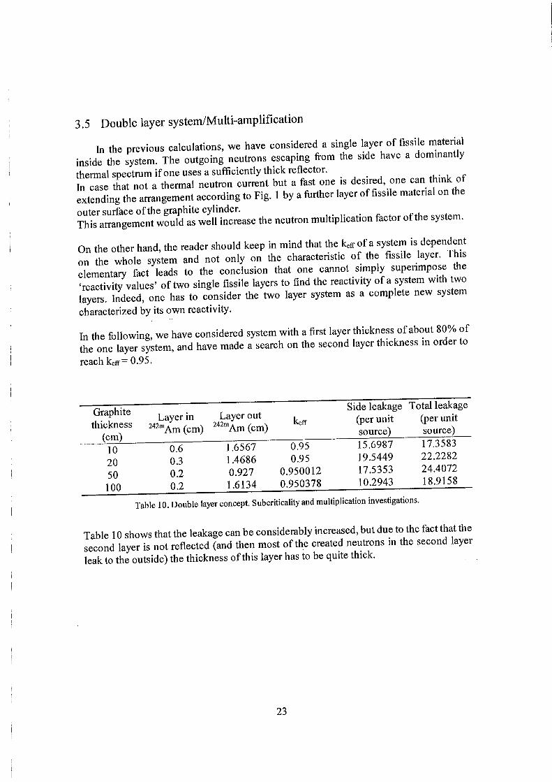
3.5 Double layer system/Multi-amplification
In the previous calculations, we have considered a single layer of fissile material inside the system. The outgoing neutrons escaping trom the side have a dominantly thermal spectrum ifone uses a sufficiently thick reflector. ,u- u In case that not a thermal neutron current but a fast one is desired, one can think of Ixtendinglhe airangement according to Fig. 1 by a fiirther layer of fissile matenal on the outer surface of the graphite cylinder. . . . . . . f,u .„ot^.^1 This arrangement would as well increase the neutron multiplication factor ofthe system.
On the other hand, the reader should keep in mind that the kefr of a system is dependent on the whole system and not only on the characteristic of the fissile layer. This elementary fact leads to the conclusion that one cannot simply superimpose the 'reactivity values' of two single fissile layers to find the reactivity of a system with ^ o layers, hideed, one has to consider the two layer system as a complete new system characterized by its own reactivity.
In the following, we have considered system with a first layer thickness of about 80% of the one layer system, and have made a search on the second layer thickness in order to reach keff=0.95.
Graphite thickness
(cm)
Layer in ^" •"Am (cm)
Layer out " ""Am (cm)
keff
Side leakage (per unit source)
Total leakage (per unit source)
10 20 50 100
0.6 0.3 0.2 0.2
1.6567 1.4686 0.927 1.6134
0.95 0.95
0.950012 0.950378
15.6987 19.5449 17.5353 10.2943
17.3583 22.2282 24.4072 18.9158
Table 10. Double layer concept. Sub criticality and multiplication investigations.
Table 10 shows that the leakage can be considerably increased, but due to the fact that tli second layer is not reflected (and then most ofthe created neutrons m the second lay. leak to the outside) the thickness of this layer has to be quite thick.
23

Energy (eV)
3x10'
2x10*
Ixio'
10" 10^ 10' 10' 10° 10' 10' 10' 10" 10= 10° 10 10 1, I . n i l iii.i.^ ••'m ' " " I ""'1 '
- tot leakage - rgt netflow
(D o
(0
Double layer system 1
10-' 10' 10-' 10° 10' 10' 10' 10' 10° 10° 10' 10°
2x10'
1x10'
-tot leakage - rgt netflow
Double layer system 3
' ^ 0 ° 10° 10' 10° 10" 10' 10' 10' 10° 10' 10' 10' 10' 10= 10° 10' 10°
Energy (eV)
10" 10' 10' 10" 10° 10' 10' 10' 10' 10° 10° 10' 10°
^ tot leakage — rgt netflow
Double layer system 2
-Ar - tot leakage • rgt netflow
Double layer system 4
V
3x10*
2x10'
1x10'
(D
m
I '
..4 § <" 2X10" I g
^ O (D C 3
1x10'
10" 10"
Figure 13. Leakage distribution for various geometries ofthe double layer concept using''""Am layers.
Ifone has a look to the Figure 13, one sees that, except ifone takes a rather large graphite layer, the neutrons going out are fast as expected.
This concept meets the same problems as the one layer concept: the leakage from the top and bottom ofthe system leads to a rather thick required amount of fissile material. This requirement is even more accentuated in this case that there is not a reflector for the second layer.
3.6 New configuration (top and bottom stopper)
The previous calculations on the cylindrical geometry, based on the geometry suggested by the previous investigations [7,8], have shown that due to the leakage fi-om
24
the top and bottom ofthe system, the required thickness ofthe fissile layer is not as small as it has been presented in previous papers. . The only way to get "thin layer" was in the use of a spherical geometry or an mfimte cylinder, and in both cases a Hohlraum with large diameter.
As the cause ofthe neutron leakage comes from the open top and bottom or the cylmder the idea to add a stopper of 50 cm of graphite on both extremities ofthe cylinder came to our mind to see how the system and its reactivity would be affected.
Our calculations have shown that when we add those stoppers the reactivity of the
systems increased drastically. _ j . , f+u^ 242mArr, In order to illustrate this fact, we have calculated the required thickness of the Am layer to obtain keff = 0.95 for systems with and without stoppers, as shown in table 11.
^"^"Am thickness ^ ""Am thickness
Pb radius Hohlraum radius Side graphite {cm)mth50em Xcm) without top (cm) (cm) thickness (cm) top and bottom and bottom ^ graphite stoppers stopper
5 10
5 20
5 50
50 0.0927 0.3065
50 0.0189 0.4257
50 0.0006 0.7934
Table 11. Comparison ofthe required thickness of'«"Am layer to obtain k.«=0.95 with and without top and bottom graphite stoppers.
One deduces that the use of stoppers improves the thermal neutron reflection which leads to a sufficient multiplication with a thin layer ^^^»Am (the order of magnitude ofthe required thickness goes from mm to ^m). , . . x, • i On the other hand, a cylinder with stopper on both side tends to be similar to a spherical geometry. The condition for a thin critical layer is also a sufficient diameter of the Hohlraum (in spherical geometiy) for the aforementioned geometrical reasons hi tab e 11 we see again the quite sudden transition from a fast to a thermal system with increasing Hohlraum diameter. The advantage of bottom and top 'stoppers is clear.
4. MCNP calculations
4.1 Verification ofthe DORT results
In order to verify our DORT results, criticality calculations have been done with
MCNP4C.
25

It has been found that the "^U based system calculations with MCNP agree fa.lrly well with the DORT calculations. As an example, we have calculated a cyhndncal booster with a 5 cm radius Pb rod inside a Hohlraum of 10 cm radius. The U thickness is equal to 0.8 cm and the graphite thickness is equal to 70 cm.
With DORT, we found for this geometry keir =0.9776 and with MCNP we found keff=0.97412 (0.96716 < keff < 0.98105 at 99% confidence).
On the other hand, when we calculated systems using a ^^^"Am layer, we^have found unexpected discrepancy. Indeed, i f we take a system based on a 0.2244 cm Am layer, with a 5 cm radius Pb rod inside a Hohlraum of 10 cm radius and graphite thickness Zng equal to 70 cm, we obtain keff equal to 0.95 and 1.04589 for DORT and MCNP calculation respectively.
This peculiar behavior led us to investigate the likely sources of discrepancy. The explanation for this discrepancy has been found and is described in the next section.
4.2 Remarks about the use of different Ubraries
The primary sources ofthe required nuclear data for the calculations (cross sections, etc) are evaluations from the ENDF/B-VI library. One should note that americium is mainly obtained by bombarding plutonium with neufrons. The only way to get Am is by chemical separation ofthe spent fiiel. This complication explains that the cross-sections of the '* '"Am are not as well-known as those of U.
As described in the previous section, in our investigations on the neutron booster we have found rather large discrepancies in the evaluation of keff with MCNP using different nuclear data libraries.
The default libraries are JEF2.2 and ENDF/B-VI for SCALE and MCNP respectively, hi the AMPX master library (the one used by SCALE) derived from the JEF2.2 nuclear data library there is only one ^"^Am isotope available corresponding to the isomer. On the other hand, for use with MCNP one can access both ENDF/B-VI and JEF2 2 libraries. In the original JEF2.2 library we found two nuclides respectively named 95242.00c and 95242 22c hi the ENDF/B-VI library, the default isomeric state of Am is named 95242 5Ic and comes actually from the ENDF/B-V evaluation (data from 1978!!). Using the above mentioned data, we obtained with MCNP4C the following results:
Library Data reference keff
ENDF/B-VI 95242.51c 1.04589
JEF2.2 95242.00c 0.95827
JEF2.2 95242.22c 0.75389
Table 12. MCNP calculations using different library data for "Am.
26

After verification, we iiave found tiiat the isomer present in the AMPX library corresponds to the 95242.00c in the JEF2.2 database. The second Am nuclide available refers to the ground state nuclide. ^ Then it turns out that using the same data for the ' '""Am layer (i.e. the one from the JEF2.2 library), DORT and MCNP4C agree fairly well.
On the other hand, the data from ENDF/B-VI gives a rather large discrepancy, certainly due to the fact that this particular data evaluation is a very old value (1978).
Table 13 illustrates the discrepancy that one can find in the different nuclear libraries:
Library Fission thermal cross section (bams)
Ground state Isomeric state
IEF2-2 ENDF/B-VI JENDL-3.2 BROND-2
2103 6886 2281 . 6700 2102 6420 2156 6985
Table 13.2200 m/s cross sections of''' Am in different data sets.
27

Conclusions and recommendations
The properties of the neutron booster have been intensively studied through systematical investigations ofthe different parameters (thickness, Hohlraum, reflector, etc) ofthe concept. The calculations were performed with determmistic codes solvmg the neutron transport equation, and those results have been partially verified with the probabilistic code MCNP. The studies have demonstrated that, with the one-layer geometry, one can have an effective multiplicafion factor of about 10~12 neutron per neutron source. Depending on the chosen geometry ofthe system (reflector thickness, single/double layer concept), one can select a thermal or fast neutron current coming out from the booster.
On the other hand, it has been calculated that the present cylindrical geometry does not appear to be the more efficient one for the use of thin layers of fissile material, hideed, the first and more important observation coming out of these studies is that the most advantageous geometry ofthe thin layer critical system is a sphere shaped hole inside an infinite (sufficiently large) piece of moderator such as graphite, covered by a thm layer ot fissile material. Criticality of such a system is made possible by the especially advantageous neutron economy, as described in the following. A very high proportion ot the fast fission neutrons gets thermalized, resulting in a high thermal flux. Fast leakage is very little i f the moderator is sufficiently large. Thermal flux attenuates at a few mean fi-ee paths distance from the fissile layer, thermal leakage is also very little with increasing moderator radius. In a good moderator, such as graphite there is little absorption, therefore a very high proportion ofthe thermal neutrons are available for absorption, and thus fission, in the fissile layer. Since the absorption cross section ofthe solid fissile material is high, the layer can be thin to avoid significant self shieldmg. The result is an essentially thermal system. Neutton lifetime is long, thermal neufrons have a high probability to get absorbed by the fiiel because the probability of any other way of getting "killed" (removal event: leakage or absorption) is very small.
This neutron balance is desfroyed i f a significant proportion of neufrons leak out. And this is not easily compensated by increasing the thickness ofthe layer. Due to the strong self-shielding there wil l not be a significant increase of thermal fissions. Fast fission can eventually compensate for the decrease of thermal fission i f the layer thickness is fiirther increased. Since the cross sections at fast neufron energies are much smaller, this is no longer a thin layer system.
'''U or In the present study, we have been investigating the possibility of usmg either '••'•"Am as likely fissile material in the neufron booster concept. We have then focused on the use of ' ' ' ' "Am based on the facts that it has the highest thermal fission cross section, that its thermal capture cross section is relatively low and the number of neufron per thermal fission is high. These nuclear properties should make it possible to obtam criticality with ulfra thin fiiel elements. We have shown that the geometry ofthe system has to be optimized in order to avoid leakage ifone wants to use thm layers of fiiel
28

material. The way to compensate the leakage is to improve the geometiy by reflecting from the top and bottom, which were open in the previously mentioned systems. With this special arrangement one goes from a fast system to a completely themiahzed system and thus the required thickness ofthe '«""Am layer is drastically reduced (fi-om a tens of mm to of order of iim). . • From a practical point of view, one has to remember that several kg of pure isomeric state ''"'"Am may have to be produced, not an entirely trivial procedure.
Another important feature for likely applications ofthe neutron booster would be bumup investigations (referring then to the fission products build up and influence on the reactivity, and the lifetime ofthe layer). This would require a detailed study with relevant knowledge of specific codes.
A special study ofthe reflector has shown that one can use Be instead of Graphite. This option allows to reduce considerably the size ofthe system keeping the similar properties than with graphite reflector. On the other hand, one has to remember that Be is a toxic material, but the poisoning eflfect of Beryllium is not prohibiting since it is used m many reactor systems. It might be a nice material for the foreseen applications.
Important lessons can be drawn fi-om this research: sufficient muhiplication with a thin fissile layer can only be obtained with a sufficient reflection coefficient for thermal neutrons ofthe reflector: this means a short slowing down length and a small curvature (large radius) ofthe Hohlraum. The smaller the slowing down length, the smaller the radius can be ofthe Hohlraum. I f the thermal reflection coefficient is too low, the system has to work on fast neutron muhiplication which requires a much thicker fissile layer because of much smaller cross sections for epithermal and fast neutrons. Beryllium is a nice moderator because the slowing down distance is smaller than in graphite and a good multiplication is obtained with a much smaller radius ofthe system The leakage is now mainly side leakage which is advantageous for the application of such a system.
The next step in the research should be a fiirther investigation of the application of Beryllium, and make calculations for real source geometiy (e.g. the lead is only in the lower half of the Hohlraum, neutrons are generated only in the center ofthe cylinder because the protons do not penetrate so far in the lead, and an axial neutron 'stopper is only possible in the lower haff assuming that the proton beam is mserted from above), using spallation spectrum for the source instead of fission spectrum.
29

References
[1] G. Chapline, Nucl. Instr. and Meth. A 271 (1988) 207.
[2] G. Chapline, Y. Matsuda, Fusion Technology 20 (1991) 719.
[3] Y. Ronen, M.J. Leibson, Trans. Israel Nucl. Soc. 14 (1987) V-42.
[4] Y. Ronen, M.J. Leibson, Nucl. Sci. Eng. 99 (1988) 278.
[5] Y. Ronen, E. Shwageraus, Nucl. hist, and Meth. in Phys. Research A (2000), to be
published.
[6] C. Rubbia: Neutrons in a highly difhisive, transparent medium: an effective neutron 'storage' device. Trans. ICENES'98, The Ninth hiternati'onal Conference on Emerging Nuclear Energy Systems, Tel-Aviv, Israel, June 28 - July 2, 1998. Vol. 1, page 4. Dan Knassim Ltd. Ramat-Gan, P.O. Box 1931, Israel.
[7] J. Magill, P. Peerani, J. van Geel, Basic Aspects of Sub-critical Systems using Fissile Layers, 3"* Int. Conf on Accelerator Driven Transmutation Technologies and Applications, Prague 7-11 June 1999.
[8] J. Magill, P. Peerani, J. van Geel, A Neutron Amplifier Assembly, European Patent Application N°. 99107327, Fo 2619 EP, 20 April 1999, Munich.
[9] European Community, Method of incineration of minor actinides in nuclear reactors. Patent submitted P-CEP-03/LU, April 26, 2000, Luxembourg.
[10] J. Magill, P. Peerani, hnproving the of minor actinides in thermal reactors by generation of fast islands with thin fissile films, to be published 2001.
[11] N.M. Greene, L.M. Petrie, XSDRNPM-S: A one dimensional Discrete Ordinates Code for Transport Analysis, Report, CCC-545, Oak Ridge National Laboratory (1983)
[12] W.A. Rhoads, R.L. Childs, The DORT two dimensional Discrete Ordinates Transport Code System, RSIC-CCCC-484, ORNL Radiation Shielding hiformation Center, Oak ridge, TN(1989).
[13] J. S. Hendricks, "MCNP4C," X-S: JSH-2000-30 (U) (February 29,2000).
[14] K. Van Tichelen, P. Kupschus, H.A. Abderrahim, "MYRRHA: Design of a Windowless Spallation Target for a Prototype Accelerator Driven System", to be published.
30

[*] "Classical" books on reactor theory are the following:
« G.I. Bell and S. Glasstone: Nuclear Reactor Theory
« S. Glasstone and M.C. Edlund: The Elements of Nuclear Reactor Theory
o J.J. Duderstadt and L.J. Hamilton: Nuclear Reactor Analysis
• J.R. Lamarsh: Introduction to Nuclear Reactor Theory
o A.M. Weinberg and E.P. Wigner: The Physical Theory of Neutron Chain
Reactors
31
List of tables
Table 1. Spherical critical thickness o f ' ' " "Am and " ' U layers (O radius = Hohlraum
radius) ^
Table 2. Spherical critical thickness of ' ' ""Am and " ' U layers with an inner Pb sphere of
5 cm radius ^
Table 3. Reflector thickness influence on the reactivity of the neutron booster with a thin
layer of "^U ^
Table 4. Layer thickness of'^^U and " ' " A m required for criticality for various infinite o
length cylinder diameters ° Table 5. Layer thickness o f ' ^ ' U and " ' " A m required for criticality for various cylinder
diameters. The calculations have been performed using the buckling correction with
a cylinder length equals to 200 cm 9
Table 6. Layer thickness of'^^U and ' " " A m required for criticality for various cylinder
diameters. The calculations have been performed using the buckling correction with
a cylinder length equals to the outer diameter ofthe system 9
Table 7a and 7b. Thickness of'^^U and " ' " A m layer required for keff=0.95 in the system
and corresponding leakage when a volumetric fission source is inserted 10
Table 8. hifluence ofthe broad group structure on the keff calculations for the booster
geometry ^ ^
Table 9. Required Be thickness to reach keflwO.95 with the required thickness of " ' " A m
layer found for keff=0.95 for various graphite thickness, with Pb rod radius equals to
5 cm and Hohlraum radius equals 10 cm. The length of the system is 1 m.
Comparison ofthe leakage for the C/Be systems 21
Table 10. Double layer concept. Subcriticality and multiplication investigations 23
Table 11. Comparison ofthe required thickness of " ' " A m layer to obtain keff=0.95 with
and without top and bottom graphite stoppers 25
Table 12. MCNP calculations using different library data for " ' " A m 26
Table 13.2200 m/s cross sections of " ' A m in different data sets 27
Table 14. Keff mesh dependence for a given geometry of a booster based on '^^U 35
32

Table 15. Working library dependence investigations for the and "Am likely
fissile material in the neutron booster concept 36
33
List of Figures
Figure 1. Critical or near critical system based on a Hohlraum, a thin actinide layer, a
moderator and a likely inner neutron source 2
Figure 2. Part ofthe INAS code system that was used for the analysis of the neutron
4 booster mvestigations
Figure 3. Required thickness o f ' ^ 'U and """Am to obtain kefpl with 2D code DORT.
The height ofthe system equals to 100 cm and the Pb rod diameter equals to 10 cm.
Cx = X cm graphite as a radial reflector 12
Figure 4. Required thickness of '^ 'U and """Am to obtain kefpO.95 with 2D code DORT.
The height ofthe system equals to 100 cm and the Pb rod diameter equals to 10 cm.
13
Figure 5. Neutron leakage per neutron source for systems with a keff=0.95 14
Figure 6. Leakage investigation with DORT for various cylindrical geometries using
" ' " A m layer
Figure 7. Influence of the keff on the leakage for various cylindrical geometries using
" ' " A m layer 16
Figure 8. Fluxes calculated inside the different materials ofthe booster 17
Figure 9. Fluxes versus system radius for four energy group calculation 18
Figure 10. Flux inside the Am layer for the thermal and epithermal groups 19
Figure 11. Initial bum-up vs. subcritical mass of the layer of " ' " A m for various
20 cylindrical systems •
Figure 12. Leakage investigation with DORT for various cylindrical geometries using
" ' " A m layer with Be as reflector 22
Figure 13. Leakage distribution for various geometries of the double layer concept using
" ' " A m layers 24
34

Appendix A: Systematic investigations ofthe technical parameters
Mesh dependence
The CSAS uses by defauhs a 4-interval mesh in each zone. This can be redefined by the use of a multiplication factor. This solution was not satisfactory for our purposes and it was then decided to use directly XSDRNPN input in order to get more flexibility with the input values.
One has to keep in mind that a good choice of coarse mesh can save both memory space and execution time without impairing the convergence of the problem. In some cases, proper application ofthe coarse mesh can help the convergence rate as well. A coarse mesh of one mean free path is ideal for many problems, hi our calculations, a finer mesh has been used for safety.
For the geometry investigations, a 10-interval mesh for the Pb zone,-the O zone and the fissile layer have been found to be optimal. For the Graphite layer, which can be from 10 cm to 100 cm thick, a 50-interval mesh is supposed to be sufficient, hideed, the mean free path of a fast neutron in graphite is about 5 cm and the mesh length should be around half of it to be accurate enough. With a 50-interval mesh and 100 cm of graphite, we obtain an interval length of 2 cm. The following table gives an example ofthe mesh influence on the keff calculation. For this study, the geometry is the following: a Pb rod of 40 cm diameter, the inner diameter of the Hohlraum is 60 cm, and the thickness of the graphite layer is 100 cm. Each zone dependence is investigated separately, i.e. when changing a mesh in one zone the other zones remains 4-interval mesh. The cylinder height is 260.6 cm (taking into account with the buckling approximation).
Zone 1 Pb
Zone 2 O low
concentration 3
Zone 3 235^
Zone 4 C
mesh nbr keff mesh nbr keff mesh nbr keff mesh nbr keff
4 1.03023 4 1.03023 4 1.03023 4 1.03023
5 1.03022 5 1.03021 5 1.03008 5 1.10745
10 1.03019 10 1.03012 10 1.02988 10 1.20765
15 1.03019 15 1.03004 15 1.02984 15 1.21891
20 1.03019 20 1.03 20 1.02983 20 1.22245
30 1.03019 30 1.02995 30 1.02983 30 1.22424
50 1.03018 50 1.02992 50 1.02983 50 1.22472
Table 14. Keff mesh dependence for a given geometry of a booster based on U.
^ In the calculations, we have used Oxygen with a low concentration (10" nuclei per unit volume) as material in the Hohlraum. This choice has been done in order to simulate void, which is never exactly obtained in experimental conditions.
35

Similarly one has to remember that the average thermal main free path for absorption m """Am is about 30 |am (when it is about 300 im for '^^U) and then should adapt the number of meshes to the required thickness ofthe fissile layer. In the calculations, except if difierently mentioned, we have used 10 mesh points for each ofthe lead, the Hohlraum and the fissile layer zone and 50 mesh points for the Graphite zone.
Workine library dependence
The use ofthe XSDRNPN module independently requires a working library, which is
made using the CSAS code.
For the criticality problems, many calculations have to be done with different thickness of the fissile material dealing with the different likely geometry investigated. It was then necessary to look at the influence of a specific working library to the criticality search in order to adjust the working library to the different problems. The following two tables show that changing the fissile medium thickness in can be done with a working library for a given geometry in a reasonably range. For the two cases, the geometry is based on Pb rod diameter or 20 cm, the inner diameter ofthe Hohlraum is 60 cm and the graphite thickness is 70 cm. The height ofthe cylinder
is 200 cm.
U 235
wku 0.5cm Thickness
(cm) 0.5 0.1 0.01
keff
1.18164 1.18134 1.17969
wku 0.1cm Thickness
keff
0.5 0.1 0.01
0.900968 0.903326 0.902625
wku 0.01 cm Thickness
(cm) 0.5 0.1 0.01
keff
0.663414 0.662428 0.668087
wkam 0.5 cm wkam 0.1cm wkam 0.01 cm
Thickness keff Thickness keff Thickness keff
(cm) (cm) (cm)
0.5 1.68985 0.5 1.29028 0.5 1.02975
0.1 1.68986 0.1 1.29182 0.1 1.03234
0.01 1.68984 0.01 1.29252 0.01 1.03392
Table 15. Working library dependence investigations for the ' " U and ''""Am likely fissile material in the neutron booster concept.
36

In table 2 numbers in italic are ketr values calculated with the working library corresponding to the actual fuel thickness. The working libraries are called wku for Uranium and wkam for Americium (e.g. the "wku 0.5 cm" is the library built with a uranium thickness of 0.5 cm). The other numbers give the keir calculated with the "wrong" libraries. It seems that the effects is very small.
Depending ofthe critical width of fuel investigations, several working libraries have been prepared on different geometry and fiiel thickness.
Order ofS„
The deterministic codes are using the method of discrete ordinate SN to solve the transport equation. The discretization ofthe space variable is left to the code user since it depends ofthe studied problem and the required accuracy. The mode.of discretization of the angular variables is inherent to the code and only the N order (defined as the number of intervals in the discretization ofthe colatitudes) can be chosen by the user.
hi our investigations, we have compared results obtain with S2, S4 and Se with a number of direction respectively equal to 6,16 and 30. The S4 has been found to be optimal and has been used in the following investigations.
Acceleration parameters
Parameters in the code can be adjusted in order to optimized the fiux convergence. Among them, we have used the following settings:
• iacc, the acceleration method in discrete ordinates, equal to 2 (partial current
rebalance) • kalf, the rebalance stabilization, equal to 0 (standard method) • ibfscl, number of flux acceleration before acceleration, equal to 1 (default) • intscl, minimum number of acceleration iterations, equal to 4 (default) • intmscl, maximum number of acceleration iterations, equal to 5 0 (default) • mode, flux extrapolation model, equal to 4 (S weighted) • isrmx, source iteration maximum, which has been adapted to the convergence
speed ofthe difierent calculations with a maximum equal to 200 • ificmi, initial fiux iteration maximum per group, equal to 50 • ifxmf, final flux iteration maximum per group, equal to 40 • eps, eigenvalue convergence criterion, equal to 10' /10" • epp, pointwise flux convergence criterion, equal to 10 /10' • theta, weighting parameter (for mode = 4), equal to 0.9 (default)
37

Appendix B: Buckling correction in XSDRNPM
XSDRNPM allows "buckling" corrections to be made for the transverse (non-calculated) dimensions in its 1-D slab and cylindrical geometries. Three input parameters-DY, DZ, and BF may be involved. ^, . , ,• In the case ofthe 1-D slab, the height DY and the width DZ can be mput. The bucklmg correction is used to account for leakage in the transverse direction and is treated analogous to an absorption cross section, that is.
Transverse Leakage = DB'cp
where B is the geometric buckling and is given by =
and Y and Z are the height and width ofthe slab, respectively, and include extrapolation
distances.
hi the case ofthe 1-D cylinder, the buckling is determined from =\^Y since only
one transverse dimension is needed.
— + i
J
The diffusion coefficient in the leakage term is determined from ^ = 7 ^ where the
transport cross-section is determined from S,, = which varies as a fiinction of
energy group and zone. The term Zsi is the within-group term from the Pi scattering
matrix.
38

Appendix C: The fine and broad energy group structure
Fine energy group
Energy boundary (eV)
Lethargy boundary Broad energy group
(41)
1 2 3
1.96E+07 1.73E+07 1.49E+07
-6.75E-01 -5.50E-01 -4.00E-01
1 1 1
4 5 6
1.38E+07 1.16E+07 l.OOE+07
-3.25E-01 -1.50E-01 O.OOE+00
2 2 2
7 8 9
8.19E+06 6.70E+06 6.07E+06
2.00E-01 4.00E-01 5.00E-01
3 3
• 3
10 11 12
5.49E+06 4.49E+06 3.68E+06
6.00E-01 8.00E-01 l.OOE+00
4 4 4
13 14 15
3.01E+06 2.47E+06 2.23E+06
1.20E+00 1.40E+00 1.50E+00
5 5 5
16 17 18
2.02E+06 1.65E+06 1.35E+06
1.60E+00 1.80E+00 2.00E+00
6 6 6
19 20 21
1.22E+06 l . l lE+06 l.OOE+06
2.10E+00 2.20E+00 2.30E+00
7 7 7
22 23 24
9.07E+05 8.21E+05 6.08E+05
2.40E+00 2.50E+00 2.80E+00
8 8 8
25 26 27
5.50E+05 4.98E+05 4.50E+05
2.90E+00 3.00E+00 3.10E+00
9 9 9
28 29 30
4.08E+05 3.02E+05 2.73E+05
3.20E+00 3.50E+00 3.60E+00
10 10 10
31 32 33
2.47E+05 1.83E+05 1.23E+05
3.70E+00 4.00E+00 4.40E+00
11 11 11
34 35
l . l lE+05 8.23E+04
4.50E+00 4.80E+00
12 12
39
Fine energy group
Energy boundary (eV)
Lethargy boundary Broad energy group
(41)
36 37 38
6.74E+04 5.52E+04 4.09E+04
5.00E+00 5.20E+00 5.50E+00
12 12 12
39 40 41 42 43
3.70E+04 2.93E+04 2.74E+04 2.48E+04 1.66E+04
5.60E+00 5.83E+00 5.90E+00 6.00E+00 6.40E+00
13 13 13 13
.13
44 45 46 47 48
1.50E+04 l . l lE+04 9.12E+03 7.47E+03 5.53E+03
6.50E+00 6.80E+00 7.00E+00 7.20E+00 7.50E+00
14 14 14
' 14 14
49 50 51 52 53
5.00E+03 3.53E+03 3.35E+03 2.25E+03 2.03E+03
7.60E+00 7.95E+00 8.00E+00 8.40E+00 8.50E+00
15 15 15 15 15
54 55 56 57 58
1.51E+03 1.43E+03 1.23E+03 l.OlE+03 9.14E+02
8.80E+00 8.85E+00 9.00E+00 9.20E+00 9.30E+00
16 16 16 16 16
59 60 61 62 63
7.49E+02 6.77E+02 4.54E+02 3.72E+02 3.04E+02
9.50E+00 9.60E+00 l.OOE+01 1.02E+01 1.04E+01
17 17 17 17 17
64 65 66 67 68
2.04E+02 1.49E+02 1.37E+02 9.17E+01 7.57E+01
1.08E+01 l . l lE+01 1.12E+01 1.16E+01 1.18E+01
18 18 18 18 18
69 70 71 72 73
6.79E+01 5.56E+01 5.16E+01 4.83E+01 4.55E+01
1.19E+01 1.21E+01 1.22E+01 1.22E+01 1.23E+01
19 19 19 19 19
40

Fine energy group
74 4.02E+01 1.24E+01 20
75 3.73E+01 1.25E+01 20
76 3.37E+01 1.26E+01 20
77 3.05E+01 1.27E+01 20
78 2.76E+01 1.28E+01 20
79 2.50E+01 1.29E+01 21
80 2.26E+01 1.30E+01 21
81 1.95E+01 1.32E+01 21
82 1.59E+01 1.34E+01 21
83 1.37E+01 1.35E+01 21
84 1.12E+01 1.37E+01 . 22
85 9.91E+00 1.38E+01 ' 22
86 9.19E+00 1.39E+01 22
87 8.32E+00 1.40E+01 23
88 7.52E+00 1.41E+01 23
89 6.16E+00 1.43E+01 23
90 5.35E+00 1.44E+01 23
91 5.04E+00 1.45E+01 23
92 4.13E+00 1.47E+01 23
93 4.00E+00 1.47E+01 23
94 3.38E+00 1.49E+01 24
95 3.30E+00 1.49E+01 24
96 2.77E+00 1.51E+01 24
97 2.72E+00 1.51E+01 24
98 2.60E+00 1.52E+01 24
99 2.55E+00 1.52E+01 24
100 2.36E+00 1.53E+01 24
101 2.13E+00 1.54E+01 25
102 2.10E+00 1.54E+01 25
103 2.02E+00 1.54E+01 25
104 1.93E+00 1.55E+01 25
105 1.84E+00 1.55E+01 25
106 1.76E+00 1.56E+01 25
107 1.67E+00 1.56E+01 25
108 1.59E+00 1.57E+01 26
109 1.50E+00 1.57E+01 26
110 1.48E+00 1.57E+01 26
111 1.44E+00 1.58E+01 26
41