new construction installation guide - · gaco · new construction installation guide 877 699 4226...
TRANSCRIPT

New Construction Installation Guide
877 699 4226 customer service | 855 639 4649 tech hotline | gaco.com MKWF5003 0916
EQUIPMENT AND ACCESSORIES
Required Equipment and Accessories
Same Proportioner, Hoses and Gun as used for Gaco’s Open Cell and Closed Cell Spray Foam
Pour Tip for Gun - recommended models include the following:
Graco Fusion Air-Purge (AP) Pour Adapter Kit, Part #
248528. This kit includes an Air Cap, 2 Teflon Rings (1 for flat
mixing chamber and 1 for round mixing chamber), and 2 feet of
hose.
Pour kits are also available for the P2 and the PMC gun.
Tips and Kits are available from your regular parts supplier.
Staplers, Staples and Air Hose - recommended models are listed below. Contact your GacoWallFoam
Area Manager for information on convenient Accessory Kits containing the recommended staplers, staples
and optional Air Hose.
Speed Stapler (for face stapling)
Bostitch Speed Stapler 21680B-ALM; ½” x 5/16” staples
Senco SFT 10-H Auto Double; ½” x 5/16” staples
Fasco F1B7C-16 Fine Wire, 11186F; ½” X 5/16” staples
Bea 80/14-450 ALM; ½”x 5/16” staples
Wide Crown Stapler (for inset stapling)
Bostitch Wide Crown Stapler 438S21; 1” x 1-1/4” staples
Senco WC 150XP Wide Crown Stapler; 1” x 1-1/4” staples
Hitachi N5024A2 Wide Crown Stapler; 1” x 1-1/4” staples
Makita AT2550A Wide Crown Stapler; 1” x 1-1/4” staples
Paslode S200-W16 Wide Crown Stapler; 1” x 1-1/4” staples
GacoProFill SYSTEM New Construction Installation Guide, Page 2
877 699 4226 customer service | 855 639 4649 tech hotline | gaco.com MKWF5003 0916
Required Equipment and Accessories (cont.)
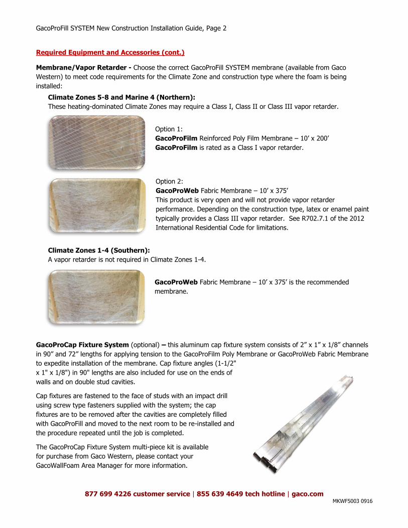
Membrane/Vapor Retarder - Choose the correct GacoProFill SYSTEM membrane (available from Gaco
Western) to meet code requirements for the Climate Zone and construction type where the foam is being
installed:
Climate Zones 5-8 and Marine 4 (Northern):
These heating-dominated Climate Zones may require a Class I, Class II or Class III vapor retarder.
Option 1:
GacoProFilm Reinforced Poly Film Membrane – 10’ x 200’
GacoProFilm is rated as a Class I vapor retarder.
Option 2:
GacoProWeb Fabric Membrane – 10’ x 375’
This product is very open and will not provide vapor retarder
performance. Depending on the construction type, latex or enamel paint
typically provides a Class III vapor retarder. See R702.7.1 of the 2012
International Residential Code for limitations.
Climate Zones 1-4 (Southern):
A vapor retarder is not required in Climate Zones 1-4.
GacoProWeb Fabric Membrane – 10’ x 375’ is the recommended
membrane.
GacoProCap Fixture System (optional) – this aluminum cap fixture system consists of 2” x 1” x 1/8” channels
in 90” and 72” lengths for applying tension to the GacoProFilm Poly Membrane or GacoProWeb Fabric Membrane
to expedite installation of the membrane. Cap fixture angles (1-1/2"
x 1" x 1/8") in 90" lengths are also included for use on the ends of
walls and on double stud cavities.
Cap fixtures are fastened to the face of studs with an impact drill
using screw type fasteners supplied with the system; the cap
fixtures are to be removed after the cavities are completely filled
with GacoProFill and moved to the next room to be re-installed and
the procedure repeated until the job is completed.
The GacoProCap Fixture System multi-piece kit is available
for purchase from Gaco Western, please contact your
GacoWallFoam Area Manager for more information.

GacoProFill SYSTEM New Construction Installation Guide, Page 3
877 699 4226 customer service | 855 639 4649 tech hotline | gaco.com MKWF5003 0916
Required Equipment and Accessories (cont.)
Proper PPE
Ensure all workers involved in the installation of GacoProFill Open Cell Foam are assigned the appropriate PPE
and have it available when arriving on jobsite. Applicators and Assistants should wear:
A NIOSH-approved full face or hood-type supplied air respirator (SAR)
MDI-resistant chemical gloves (e.g., nitrile), or fabric gloves coated in nitrile, neoprene, butyl, or PVC
Chemically resistant long-sleeve coveralls or chemically resistant full body suit with hood
MDI-resistant fitted boots/booties
Please visit www.spraypolyurethane.org for additional information.
GacoProFill SYSTEM New Construction Installation Guide, Page 4
877 699 4226 customer service | 855 639 4649 tech hotline | gaco.com MKWF5003 0916
GENERAL PROCEDURES
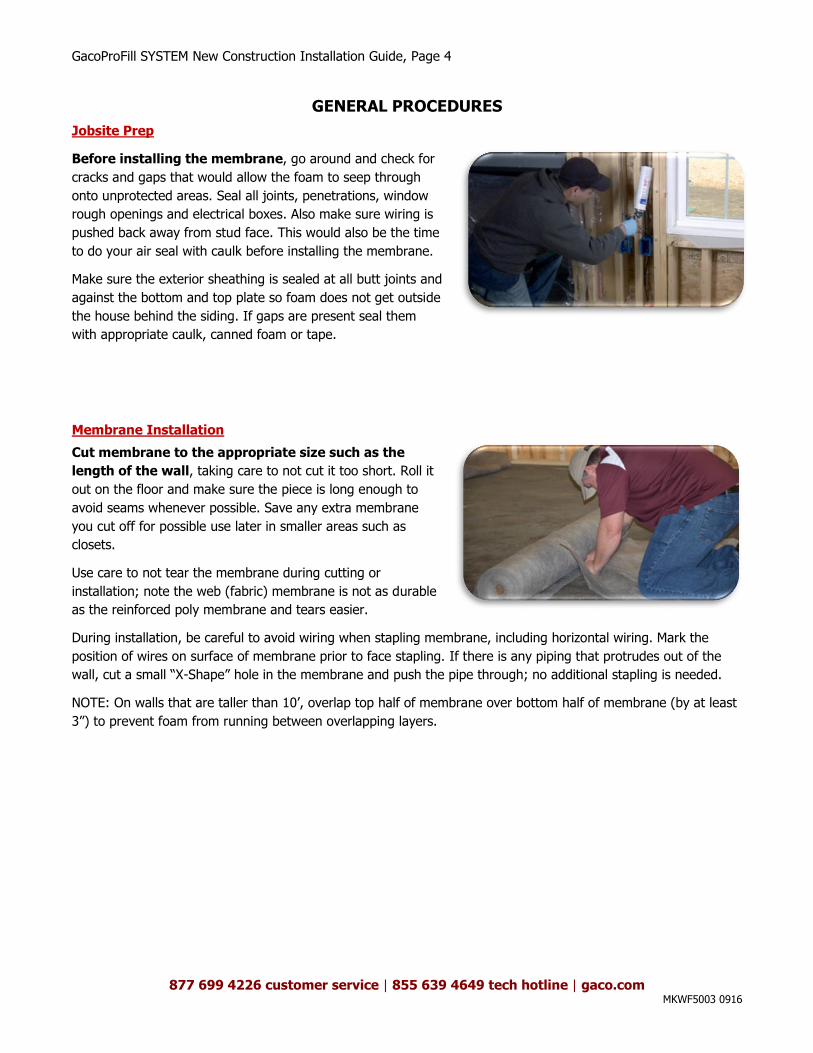
Jobsite Prep
Before installing the membrane, go around and check for
cracks and gaps that would allow the foam to seep through
onto unprotected areas. Seal all joints, penetrations, window
rough openings and electrical boxes. Also make sure wiring is
pushed back away from stud face. This would also be the time
to do your air seal with caulk before installing the membrane.
Make sure the exterior sheathing is sealed at all butt joints and
against the bottom and top plate so foam does not get outside
the house behind the siding. If gaps are present seal them
with appropriate caulk, canned foam or tape.
Membrane Installation
Cut membrane to the appropriate size such as the
length of the wall, taking care to not cut it too short. Roll it
out on the floor and make sure the piece is long enough to
avoid seams whenever possible. Save any extra membrane
you cut off for possible use later in smaller areas such as
closets.
Use care to not tear the membrane during cutting or
installation; note the web (fabric) membrane is not as durable
as the reinforced poly membrane and tears easier.
During installation, be careful to avoid wiring when stapling membrane, including horizontal wiring. Mark the
position of wires on surface of membrane prior to face stapling. If there is any piping that protrudes out of the
wall, cut a small “X-Shape” hole in the membrane and push the pipe through; no additional stapling is needed.
NOTE: On walls that are taller than 10’, overlap top half of membrane over bottom half of membrane (by at least
3”) to prevent foam from running between overlapping layers.
GacoProFill SYSTEM New Construction Installation Guide, Page 5
877 699 4226 customer service | 855 639 4649 tech hotline | gaco.com MKWF5003 0916
Membrane Installation – Face Stapling
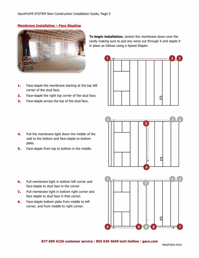
To begin installation, stretch the membrane down over the
cavity making sure to pull any wires out through it and staple it
in place as follows using a Speed Stapler.
1. Face-staple the membrane starting at the top left
corner of the stud face.
2. Face-staple the right top corner of the stud face.
3. Face-staple across the top of the stud face.
4. Pull the membrane tight down the middle of the
wall to the bottom and face-staple to bottom
plate.
5. Face-staple from top to bottom in the middle.
6. Pull membrane tight in bottom left corner and
face-staple to stud face in the corner
7. Pull membrane tight in bottom right corner and
face staple to stud face in that corner.
8. Face-staple bottom plate from middle to left
corner, and from middle to right corner.
GacoProFill SYSTEM New Construction Installation Guide, Page 6
877 699 4226 customer service | 855 639 4649 tech hotline | gaco.com MKWF5003 0916
Membrane Installation – Face Stapling (cont.)
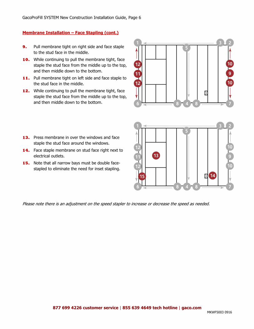
9. Pull membrane tight on right side and face staple
to the stud face in the middle.
10. While continuing to pull the membrane tight, face
staple the stud face from the middle up to the top,
and then middle down to the bottom.
11. Pull membrane tight on left side and face staple to
the stud face in the middle.
12. While continuing to pull the membrane tight, face
staple the stud face from the middle up to the top,
and then middle down to the bottom.
13. Press membrane in over the windows and face
staple the stud face around the windows.
14. Face staple membrane on stud face right next to
electrical outlets.
15. Note that all narrow bays must be double face-
stapled to eliminate the need for inset stapling.
Please note there is an adjustment on the speed stapler to increase or decrease the speed as needed.
GacoProFill SYSTEM New Construction Installation Guide, Page 7
877 699 4226 customer service | 855 639 4649 tech hotline | gaco.com MKWF5003 0916
Membrane Installation (cont.)
To complete the installation, choose one of the following options:
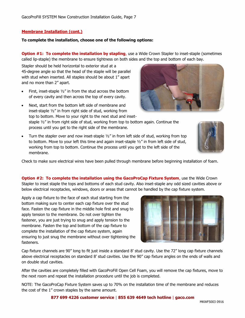
Option #1: To complete the installation by stapling, use a Wide Crown Stapler to inset-staple (sometimes
called lip-staple) the membrane to ensure tightness on both sides and the top and bottom of each bay.
Stapler should be held horizontal to exterior stud at a
45-degree angle so that the head of the staple will be parallel
with stud when inserted. All staples should be about 1” apart
and no more than 2” apart.
First, inset-staple ½” in from the stud across the bottom
of every cavity and then across the top of every cavity.
Next, start from the bottom left side of membrane and
inset-staple ½” in from right side of stud, working from
top to bottom. Move to your right to the next stud and inset-
staple ½” in from right side of stud, working from top to bottom again. Continue the
process until you get to the right side of the membrane.
Turn the stapler over and now inset-staple ½” in from left side of stud, working from top
to bottom. Move to your left this time and again inset-staple ½” in from left side of stud,
working from top to bottom. Continue the process until you get to the left side of the
membrane.
Check to make sure electrical wires have been pulled through membrane before beginning installation of foam.
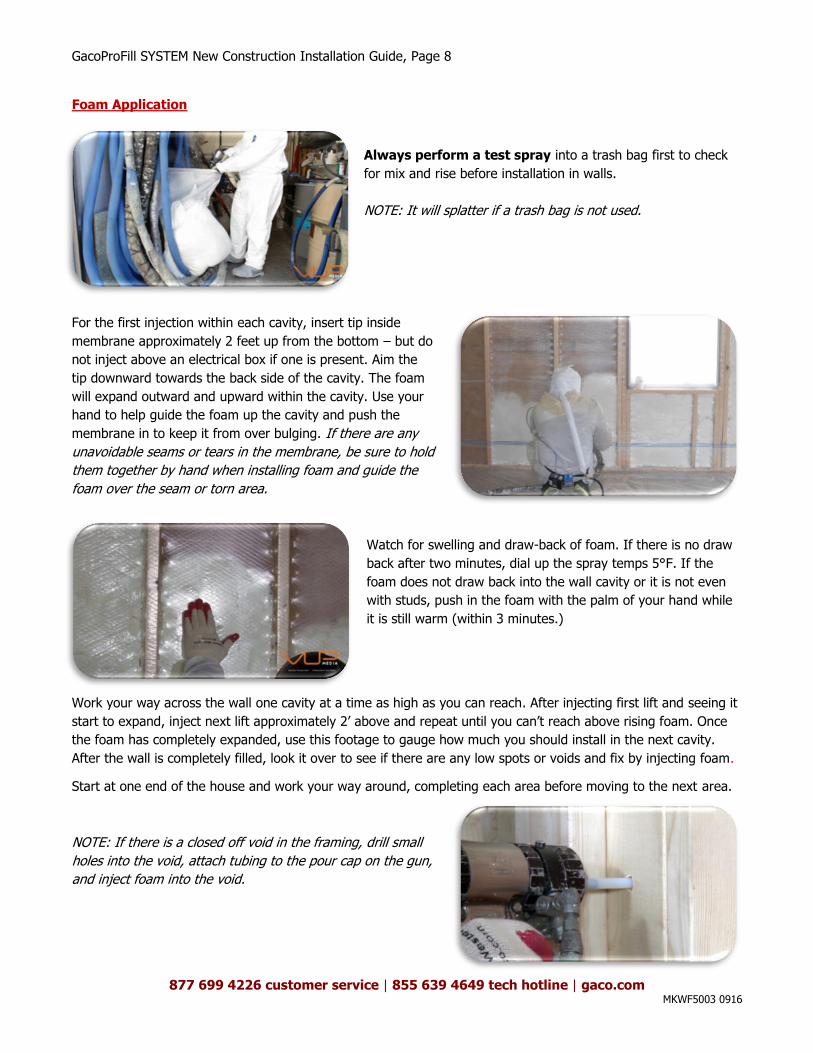
Option #2: To complete the installation using the GacoProCap Fixture System, use the Wide Crown
Stapler to inset staple the tops and bottoms of each stud cavity. Also inset-staple any odd sized cavities above or
below electrical receptacles, windows, doors or areas that cannot be handled by the cap fixture system.
Apply a cap fixture to the face of each stud starting from the
bottom making sure to center each cap fixture over the stud
face. Fasten the cap fixture in the middle hole first and snug to
apply tension to the membrane. Do not over tighten the
fastener, you are just trying to snug and apply tension to the
membrane. Fasten the top and bottom of the cap fixture to
complete the installation of the cap fixture system, again
ensuring to just snug the membrane without over tightening the
fasteners.
Cap fixture channels are 90” long to fit just inside a standard 8’ stud cavity. Use the 72” long cap fixture channels
above electrical receptacles on standard 8’ stud cavities. Use the 90” cap fixture angles on the ends of walls and
on double stud cavities.
After the cavities are completely filled with GacoProFill Open Cell Foam, you will remove the cap fixtures, move to
the next room and repeat the installation procedure until the job is completed.
NOTE: The GacoProCap Fixture System saves up to 70% on the installation time of the membrane and reduces
the cost of the 1” crown staples by the same amount.
GacoProFill SYSTEM New Construction Installation Guide, Page 8
877 699 4226 customer service | 855 639 4649 tech hotline | gaco.com MKWF5003 0916
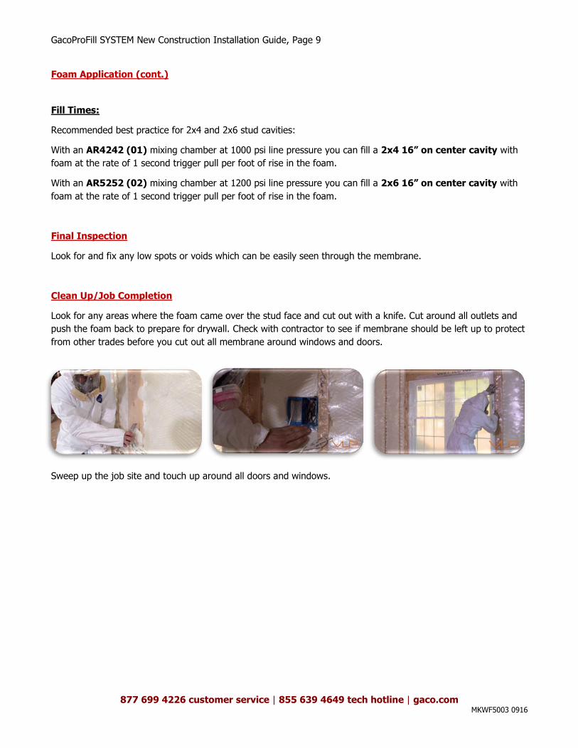
Foam Application
Always perform a test spray into a trash bag first to check
for mix and rise before installation in walls.
NOTE: It will splatter if a trash bag is not used.
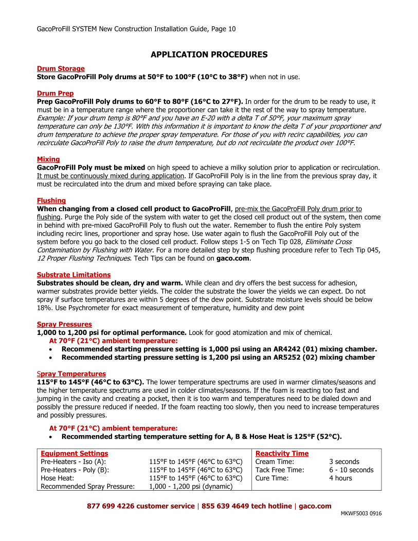
For the first injection within each cavity, insert tip inside
membrane approximately 2 feet up from the bottom – but do
not inject above an electrical box if one is present. Aim the
tip downward towards the back side of the cavity. The foam
will expand outward and upward within the cavity. Use your
hand to help guide the foam up the cavity and push the
membrane in to keep it from over bulging. If there are any
unavoidable seams or tears in the membrane, be sure to hold
them together by hand when installing foam and guide the
foam over the seam or torn area.
Watch for swelling and draw-back of foam. If there is no draw
back after two minutes, dial up the spray temps 5°F. If the
foam does not draw back into the wall cavity or it is not even
with studs, push in the foam with the palm of your hand while
it is still warm (within 3 minutes.)
Work your way across the wall one cavity at a time as high as you can reach. After injecting first lift and seeing it
start to expand, inject next lift approximately 2’ above and repeat until you can’t reach above rising foam. Once
the foam has completely expanded, use this footage to gauge how much you should install in the next cavity.
After the wall is completely filled, look it over to see if there are any low spots or voids and fix by injecting foam.
Start at one end of the house and work your way around, completing each area before moving to the next area.
NOTE: If there is a closed off void in the framing, drill small
holes into the void, attach tubing to the pour cap on the gun,
and inject foam into the void.
GacoProFill SYSTEM New Construction Installation Guide, Page 9
877 699 4226 customer service | 855 639 4649 tech hotline | gaco.com MKWF5003 0916
Foam Application (cont.)
Fill Times:
Recommended best practice for 2x4 and 2x6 stud cavities:
With an AR4242 (01) mixing chamber at 1000 psi line pressure you can fill a 2x4 16” on center cavity with
foam at the rate of 1 second trigger pull per foot of rise in the foam.
With an AR5252 (02) mixing chamber at 1200 psi line pressure you can fill a 2x6 16” on center cavity with
foam at the rate of 1 second trigger pull per foot of rise in the foam.
Final Inspection
Look for and fix any low spots or voids which can be easily seen through the membrane.
Clean Up/Job Completion
Look for any areas where the foam came over the stud face and cut out with a knife. Cut around all outlets and
push the foam back to prepare for drywall. Check with contractor to see if membrane should be left up to protect
from other trades before you cut out all membrane around windows and doors.
Sweep up the job site and touch up around all doors and windows.
GacoProFill SYSTEM New Construction Installation Guide, Page 10
877 699 4226 customer service | 855 639 4649 tech hotline | gaco.com MKWF5003 0916
APPLICATION PROCEDURES
Drum Storage
Store GacoProFill Poly drums at 50°F to 100°F (10°C to 38°F) when not in use.
Drum Prep Prep GacoProFill Poly drums to 60°F to 80°F (16°C to 27°F). In order for the drum to be ready to use, it
must be in a temperature range where the proportioner can take it the rest of the way to spray temperature. Example: If your drum temp is 80°F and you have an E-20 with a delta T of 50°F, your maximum spray temperature can only be 130°F. With this information it is important to know the delta T of your proportioner and drum temperature to achieve the proper spray temperature. For those of you with recirc capabilities, you can recirculate GacoProFill Poly to raise the drum temperature, but do not recirculate the product over 100°F. Mixing
GacoProFill Poly must be mixed on high speed to achieve a milky solution prior to application or recirculation.
It must be continuously mixed during application. If GacoProFill Poly is in the line from the previous spray day, it must be recirculated into the drum and mixed before spraying can take place.
Flushing
When changing from a closed cell product to GacoProFill, pre-mix the GacoProFill Poly drum prior to flushing. Purge the Poly side of the system with water to get the closed cell product out of the system, then come
in behind with pre-mixed GacoProFill Poly to flush out the water. Remember to flush the entire Poly system
including recirc lines, proportioner and spray hose. Use water again to flush the GacoProFill Poly out of the system before you go back to the closed cell product. Follow steps 1-5 on Tech Tip 028, Eliminate Cross Contamination by Flushing with Water. For a more detailed step by step flushing procedure refer to Tech Tip 045, 12 Proper Flushing Techniques. Tech Tips can be found on gaco.com.
Substrate Limitations Substrates should be clean, dry and warm. While clean and dry offers the best success for adhesion,
warmer substrates provide better yields. The colder the substrate the lower the yields we can expect. Do not spray if surface temperatures are within 5 degrees of the dew point. Substrate moisture levels should be below
18%. Use Psychrometer for exact measurement of temperature, humidity and dew point
Spray Pressures
1,000 to 1,200 psi for optimal performance. Look for good atomization and mix of chemical. At 70°F (21°C) ambient temperature:
Recommended starting pressure setting is 1,000 psi using an AR4242 (01) mixing chamber.
Recommended starting pressure setting is 1,200 psi using an AR5252 (02) mixing chamber
Spray Temperatures
115°F to 145°F (46°C to 63°C). The lower temperature spectrums are used in warmer climates/seasons and
the higher temperature spectrums are used in colder climates/seasons. If the foam is reacting too fast and jumping in the cavity and creating a pocket, then it is too warm and temperatures need to be dialed down and
possibly the pressure reduced if needed. If the foam reacting too slowly, then you need to increase temperatures and possibly pressures.
At 70°F (21°C) ambient temperature:
Recommended starting temperature setting for A, B & Hose Heat is 125°F (52°C).
Equipment Settings Pre-Heaters - Iso (A): 115°F to 145°F (46°C to 63°C)
Pre-Heaters - Poly (B): 115°F to 145°F (46°C to 63°C) Hose Heat: 115°F to 145°F (46°C to 63°C)
Recommended Spray Pressure: 1,000 - 1,200 psi (dynamic)
Reactivity Time Cream Time: 3 seconds
Tack Free Time: 6 - 10 seconds Cure Time: 4 hours