new cutter design to minimize part deflection in
TRANSCRIPT
NEW CUTTER DESIGN TO MINIMIZE PART
DEFLECTION IN MACHINING THIN WALL LOW
RIGIDITY COMPONENT
MOHD NORAZZIM BIN MOHD HASHIM
B050910049
UNIVERSITI TEKNIKAL MALAYSIA MELAKA
2012

B0
50
91
00
49 B
AC
HE
LO
R O
F M
AN
UF
AC
TU
RIN
G E
NG
INE
ER
ING
(MA
NU
FA
CT
UR
ING
PR
OC
ES
S) (H
ON
S.) 2
012 U
TeM

UNIVERSITI TEKNIKAL MALAYSIA MELAKA
NEW CUTTER DESIGN TO MINIMIZE PART DEFLECTION IN
MACHINING THIN WALL LOW RIGIDITY COMPONENT
This report submitted in accordance with requirement of the Universiti Teknikal
Malaysia Melaka (UTeM) for the Bachelor Degree of Manufacturing Engineering
(Process) (Hons.)
by
MOHD NORAZZIM BIN MOHD HASHIM
B050910049
870917055011
FACULTY OF MANUFACTURING ENGINEERING
2012

UNIVERSITI TEKNIKAL MALAYSIA MELAKA
BORANG PENGESAHAN STATUS LAPORAN PROJEK SARJANA MUDA
TAJUK: New cutter design to minimize part deflection in machining thin wall low rigidity component
SESI PENGAJIAN: 2011/12 Semester 2 Saya MOHD NORAZZIM BIN MOHD HASHIM mengaku membenarkan Laporan PSM ini disimpan di Perpustakaan Universiti Teknikal Malaysia Melaka (UTeM) dengan syarat-syarat kegunaan seperti berikut:
1. Laporan PSM adalah hak milik Universiti Teknikal Malaysia Melaka dan penulis. 2. Perpustakaan Universiti Teknikal Malaysia Melaka dibenarkan membuat salinan
untuk tujuan pengajian sahaja dengan izin penulis. 3. Perpustakaan dibenarkan membuat salinan laporan PSM ini sebagai bahan
pertukaran antara institusi pengajian tinggi.
4. **Sila tandakan (√)
SULIT
TERHAD
TIDAK TERHAD
(Mengandungi maklumat yang berdarjah keselamatan atau kepentingan Malaysiasebagaimana yang termaktub
dalam AKTA RAHSIA RASMI 1972)
(Mengandungi maklumat TERHAD yang telah ditentukan
oleh organisasi/badan di mana penyelidikan dijalankan)
Alamat Tetap:
39-2A Jalan 1B/133, Taman Sri
Sentosa, Jalan Kelang Lama,
58000 Kuala Lumpur
Tarikh: _________________________
Disahkan oleh:
Cop Rasmi:
Tarikh: 29 JUNE 2012
** Jika Laporan PSM ini SULIT atau TERHAD, sila lampirkan surat daripada pihak berkuasa/organisasi berkenaan dengan menyatakan sekali sebab dan tempoh laporan PSM ini perlu dikelaskan sebagai SULIT atau TERHAD.

DECLARATION
I hereby, declared this report entitled “New cutter design to minimize part deflection in machining thin wall low rigidity component” is the results of my own research
except as cited in references.
Signature :
Author’s Name : MOHD NORAZZIM BIN MOHD HASHIM
Date : 29 JUNE 2012
APPROVAL
This report is submitted to the Faculty of Manufacturing Engineering of UTeM
as a partial fulfillment of the requirements for the degree of Bachelor of
Manufacturing Engineering (Process) (Hons.). The member of the supervisory is
as follow:
………………………………
ABSTRAK
Untuk pengilang komponen struktur aeroangkasa, permintaan bagi alat pemotong
yang berprestasi tinggi adalah pra-syarat kerana lebih daripada 80% bahan dipotong
adalah untuk menghasilkan komponen monolitik. Di samping itu, kerja permintaan
permukaan profil yang berkualiti yang tinggi terhadap komponen monolitic
mempuayai ketebalan dinding yang nipis. Disebabkan ketebalan yang nipis pada
permukaan dinidng,ubah bentuk selalu terjadi dalam pemesinan dinding nipis dimana
mengakibatkan kecacatan pada ukuran permukaan. Oleh itu, proses pemesinan ini
memerlukan alat pemotong khas bagi mengawal kecacatan pada permukaan. Projek
ini, cuba untuk menyiasat dan menganalisis kesan bilangan gigi pada alat pemotong
terhadap magnitud ralat ukuran permukaan dan prestasi pemesinan apabila
pemesinan dilakukan pada bahagian dinding yang nipis dan ketegaran rendah. Pada
akhir pemesinan, apa yang dapat dilihat adalah keputusan analisis dari sudut
kerosakan pada permukaan, daya pemotongan dan kekasaran permukaan dengan
mengunakan alat pemotong yang berbeza gigi. Analisis akan menunjukkan bahawa
samada bilangan gigi pada alat pemotong menpengaruhi benda kerja. Selain itu, daya
permotongan menpengaruhi kerosakan pada permukaan.

ABSTRACT
For aerospace structural component manufacturer, the demand for the high-
performance cutting tools is pre-requisite as more than 80% of the material is cut
away to produce the monolithic component. In addition, this works demand high
quality surface profile as most of the monolithic component contains a thin-wall
feature. Because of the poor stiffness of thin-wall feature, deformation is more likely
to occur in the machining of thin-wall part which result a dimensional surface errors.
Thus, this machining process needs a special cutting tool for effectively control the
surface errors. This project attempts to investigate and analyse the effect of flute
number of end mill cutter on the magnitude of dimensional surface errors and
machining performance when machining thin-wall low rigidity part. At the end of
machining, what is seen are the results of analysis of surface error, cutting force and
surface roughness by using different flutes. The analysis will show that either the
number of flute on cutting tool will influence the workpiece surface. In addition,
cutting force is influence the surface error

DEDICATION
This dedication is for my mother and father, who always pray for my safety and
health. Thanks to them because always be my side no matter what happen.
Without blessing from them, maybe I’m not here. All guidance and advice given by
them always I follow. For me, their prayer is keys of my success. I am grateful
because I have them as my parents. Thank you, Allah.
Also thanks a lot to my supervisor, Dr Raja Izamshah Bin Raja Abdullah
for their support and care.

ACKNOWLEDGEMENT
Alhamdulillah, Thanks to the entire Almighty from Allah for giving me all the
strength and good health to complete this report without problems and barriers. This
report is finally completed with much assistance of many people.
I would like to express the deepest appreciation to Universiti Teknikal Melaysia
Melaka for providing such a brilliant facility such as equipment and machine for me
to fulfil PSM requirement that’s need to use while the project is carry on .
Besides that, I am heartily thankful to my supervisor, En. Raja Izamshah Bin Raja
Abdullah, whose encouragement, guidance and support from the initial to the final
level enabled me to develop an understanding of the research. I am truly grateful for
his the time spent proofreading and correcting my many mistakes, his tolerance of
my mistakes, and his commitment to my future career.
In addition, I would like to thank all manufacturing engineering department lab staff
for giving me an opportunity to work in a good and productive environment. Their
continuous support and guidance whenever problems occurred while I was
performing new task is really an encouragement in making me to perform at my very
best. This has partly contributed to the success of my research and the completion of
this ‘Projek Sarjana Muda’.
Last but not least I would like to thank my friends especially those who help to
contribute the idea and solution while the research is carry on. Thank you.

TABLE OF CONTENT
Abstrak i
Abstract ii
Dedication iii
Acknowledgement iv
Table of Content v
List of Tables vii
List of Figures viii
List Abbreviations, Symbols and Nomenclature x
CHAPTER 1 : INTRODUCTION 1
1.1 Research Background 1
1.2 Problem Statement 2
1.3 Research Objectives 3
1.4 Scope of Project 3
CHAPTER 2: LITERATURE RIVIEW 4
2.1 Related Study 4
2.2 End Milling 6
2.3 Geometric Feature of End Mill 7
2.4 Flute 10
2.4.1 Effect of flute number 11
2.5 Thin wall part 11
2.6 Cutting tool material 12
2.6.1 High Speed Steel 13
2.6.2 Carbide 13
2.7 Aluminium 14
CHAPTER 3: METHODOLOGY 15
3.1 Introduction 15
3.2 Flow Chart 16
3.3 Cutting tool parameter 17
3.4 Work Piece 17
3.4.1 Part Modelling 17
3.4.2 Machining process 21
3.5 Test/Machining 24
3.5.1 Performance Measurement 24
3.6 Summary 27
CHAPTER 4: RESULT & ANALYSIS
4.1 Introduction 28
4.2 Surface Error 30
4.2.1 3D Graph 30
4.2.2 3D Graph thickness 6-4mm 31
4.2.3 Analysis 6-4mm 34
4.2.4 3D Graph thickness 4-2mm 34
4.2.5 Analysis 4-2mm 37
4.3 Cutting force, Fx 37
4.3.1 Cutting Force Graph 6-4mm 38
4.3.2 Analysis cutting force 40
4.3.3 Cutting Force 4-2 mm 41
4.3.4 Analysis cutting force 42
4.4 Surface Roughness 43
4.4.1 Thickness 6 mm to 4 mm 44
4.4.2 Thickness 4 mm to 2 mm 45
CHAPTER 5 CONCLUSION 48
5.1 Conclusion 48
REFERENCES
APPENDICES
A PSM 1 Gantt Chart
B PSM 2 Gantt Chart
C Reading of surface error of 6 - 4mm (4 and 5 flute)
D Reading of surface error of 6 - 4mm (6 and 7 flute)
E Reading of surface error of 6 - 4mm (8 flute)
F Reading of surface error of 4 - 2mm (4 and 5 flute)
G Reading of surface error of 4 - 2mm (6 and 7 flute)
H Reading of surface error of 4 - 2mm (8 flute)
I Surface roughness result 6-4 mm (4, 5 and 6 flute)
J Surface roughness result 6-4 mm (7 and 8 flute)
K Surface roughness result 4 -2 mm (4, 5 and 6 flute)
L Surface roughness result 4 -2 mm (7 and 8 flute)
LIST OF TABLES
2.1 Feature Dimension 8
3.1 Parameter 16
3.2 Dimension Thin wall 23
4.1 Flute 28
4.2 Cutting Tool Dimension 29
4.3 Thickness 6mm to 4mm 43
4.4 Thickness 4mm to 2mm 44

LIST OF FIGURES
1.1 Aerospace monolithic component 1
2.1 Variety of end mills 6
2.2 Two Flutes 7
2.3 Multi Flute 7
2.4 Geometry Feature 8
2.5 Angle Geometry 8
2.6 Geometry of End mill 9
2.7 Rake Angle 9
2.8 Flute 10
2.9 Thin wall work piece 12
3.1 Methodology Flow Chart 16
3.2 Dimension (50 mm x 120 mm) 17
3.3 Extrude/Pad (11.8 mm) 18
3.4 Solid Part 18
3.5 Constraint 19
3.6 Extrude/Pad (38.1 mm) 19
3.7 Final part 20
3.8 Isometric view 20
3.9 Thin wall part before machining 21
3.10 Start machining 21
3.11 Overall Machining 22
3.12 Stock Aluminium 23
3.13 Thin wall dimension 23
3.14 Points to measure 24
3.15 Mitutoyo CNC CMM 25
3.16 Mitutoyo Microscope 26
3.17 Surface to measure 26

3.18 Mitutoyo surface roughness tester 27
3.19 Example Ra Graft 27
4.1 Five Cutting tool 28
4.2 Cutting Tool Dimension 29
4.3 Workpiece (Thin wall part) 30
4.4 Zone 31
4.5 4 Flute (6-4mm) 31
4.6 5 Flute (6-4mm) 32
4.7 6 Flute (6-4mm) 32
4.8 7 Flute (6-4mm) 33
4.9 8 Flute (6-4mm) 33
4.10 4 Flute (4-2mm) 34
4.11 5 Flute (4-2mm) 35
4.12 6 Flute (4-2mm) 35
4.13 7 Flute (4-2mm) 36
4.14 8 Flute (4-2mm) 36
4.15 4 Flute graph (6-4mm) 38
4.16 5 Flute graph (6-4mm) 38
4.17 6 Flute graph (6-4mm) 39
4.18 7 Flute graph (6-4mm) 39
4.19 8 Flute graph (6-4mm) 40
4.20 4 Flute graph (4-2mm) 41
4.21 5 Flute graph (4-2mm) 41
4.22 6 Flute graph (4-2mm) 42
4.23 7 Flute graph (4-2mm) 42
4.24 8 Flute graph (4-2mm) 43
4.25 Measurement Level 44
LIST OF ABBREVIATIONS, SYMBOLS AND
NOMENCLATURE
% - Percent
Al - Aluminium
CAM - Computer Aided Manufacturing
Catia - Computer Aided Three-Dimensional Interactive
CMM - Coordinate Measuring Machine
CNC - Computer Numerical Control
Cº - Degree Celsius
FEA - Finite Element Analysis
HSS
HV
-
-
High Speed Steel
Hardness Vickel
m - meter
min - minute
mm - millimetre
Mpa - Mega Pascal
NC - Numerical Control
Ra - Arithmetic Average of Absolute Value
RPM - Revolution Per Minute
Ti - Titanium
1
1.1 Research Background
Demand for the next generation, cost effective, high performance aircrafts has
motivating the aerospace industry to use non-traditional materials and new aircraft
structural design. New aircraft are design with one piece flow of monolithic
component to replace large number of assembled component. This new monolithic
structural components allows for higher quality and reduce the manufacturing times.
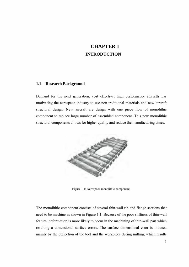
Figure 1.1: Aerospace monolithic component.
The monolithic component consists of several thin-wall rib and flange sections that
need to be machine as shown in Figure 1.1. Because of the poor stiffness of thin-wall
feature, deformation is more likely to occur in the machining of thin-wall part which
resulting a dimensional surface errors. The surface dimensional error is induced
mainly by the deflection of the tool and the workpiece during milling, which results
INTRODUCTION
CHAPTER 1
2
in a deviation of the depth of cut. If the cutter and workpiece have high rigidity, the
deflection of the cutter and workpiece are small and can be neglected in the
distribution of surface dimensional error. However, in the peripheral milling of a
very flexible component, the deflection is significant. The process is further
complicated by periodically varying milling forces, which statically and dynamically
excite the tool and part structures, leading to significant and often unpredictable
deflections.
1.2 Problem Statement
Machining errors can be broadly classified as geometric errors, thermal induced
errors cutting force induced errors and other errors. The errors caused by cutting
forces depend on the type of tool and workpiece and the specific cutting conditions
and parameters. For machining low rigidity thin-walled parts, the force induced part
deflection has a significant contribution to the total surface error. The tight
dimensional tolerance of aerospace component poses a great challenge for the
manufacturer especially for machining component that contains a thin wall feature.
Tool geometry has a direct influence on the cutting performance such as the cutting
forces, quality of machined surface, shapes accuracy, cutting edge wear and tool life.
The geometric parameters of end mills include the number of flute, edge shape, rake
angle, relief angle, helix angle and clearance angle. Each of the geometric features
has their own function and need to be considered for a specific machining
application.

3
1.3 Research Objectives
Most of the existing research on machining thin-wall component concentrated on the
process planning, little attention is emphasize on the effect of cutting tool on the
occurrence of the surface error and machining performance. Driven by the need to
constantly increase the machining efficiency and part accuracy, the objectives of this
project are to:
a) Investigate and analyse the effect of end mill flute number on the magnitude
of dimensional surface errors when machining thin-wall low rigidity part,
b) Investigate and analyse the effect of end mill flute number on the machining
performance namely cutting forces and surface roughness.
1.4 Scope of Project
This project focuses on the effects number of flute of end mill cutter on the
magnitude of dimensional surface errors and machining performance when
machining thin-wall low rigidity part. Five carbide end mill cutters with different
number of flute will be design and fabricate using a CNC tool cutter grinder
machine. Then, a side-milling experiment will be conduct on aluminium thin-wall
workpiece to analyse the effects on number of end mill flute. The evaluation of
machining performance consists of the magnitudes of surface errors, cutting forces
and surface roughness.
4
2.1 Related Study
So far, there is still no other specific journal research about the cutting tool for end
mill but there is some other journal that can be related to cutting tool which is cutting
force. In their study, cutting force in machining of thin wall parts is due of variable
part or tool deflection. All the study talk about the a new analytical force model, a
method that predicts cutting force, develop a cutting force model, proposed a
mechanistic model for cutting force and approach to identify cutting force
coefficients.
Min et.al (2006) propose a new mechanistic cutting force model for flat end milling
using the instantaneous cutting force coefficients. State that the total cutting forces
can be separated into two terms which is nominal component independent of the run
out and a perturbation component induced by the run out. To calibrate the cutting
force coefficients the instantaneous value of nominal component is used. In early
studies of milling process, Min et.al (2006), state that cutting force models were
develop based on the nominal instantaneous uncut chip thickness without run out and
more milling force models were proposed. Also state that dynamometer can be used
to measure a cutting force. Form other viewpoint, Cho et.al proposed an alternative
approach to use instantaneous cutting force for the calibration of cutting force
coefficients and the evaluation of run out parameters in end milling. Advantage of
this method is only needs a few test to do calibration procedure which is can reduce
large number of experiment or testing.
LITERATURE REVIEW
CHAPTER 2
5
S.Ratchev et.al (2004) study about a flexible force model for end milling of low-
rigidity parts which is there is a high complexity associated with modeling of cutting
forces in machining of thin-wall parts due to the variable part/tool deflection and
changing tool immersion angle. The cutting forces in machining of low-rigidity
deflecting parts depend on the chip thickness which is a function of the tool
immersion angle. In machining low-rigidity parts the tool immersion angle is a
function of the part deflection which itself depends on the cutting forces. S.Ratchev
et.al (2004) study the develop method from another research based on cutting force
of oblique cutting. For example, Budak et.al (1996), predicts the milling force
coefficients from an orthogonal cutting database and a generic oblique cutting
analysis where this method can be applied to more complex tool designs by
eliminates the need for experimental calibration for each milling tool geometry.
Based on theory of oblique cutting, Ikua et.al (2001), predicts the cutting force and
machining error assuming instantaneous rigid force model in calculating chip
thickness and cutting forces by presented a theoretical model. Meanwhile, Klineet.al
(1982) using the finite element (FE) method to model the part to proposed a
mechanistic model for cutting force prediction combined with a model for cutter and
work piece deflections. Feng and Meng (1994) developed a cutting force model
based on the mechanistic principles of metal cutting. Also propose a mechanistic
force model for predicting the machining errors caused by tool deflection is Lim et.al
(1995).
2.2 End Milling
End mill is a type of milling cutter which is cutting tool that used for many
applications in industrial milling. In application of end mills is used in milling
applications such as tracer milling profile milling, face milling, and plunging. In
selection and use of end mills, some precautions should be taken for best result also
for the safety. An ample power of milling machine should be used and also by select
a proper design of end mill and mount it with the least possible overhang. It
important to ensure that end mill is sharp and must run as concentric as possible.
(Metal Cutting Tool Handbook 1989)
6
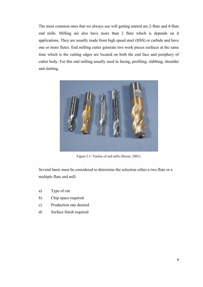
The most common ones that we always use will getting started are 2-flute and 4-flute
end mills. Milling are also have more than 2 flute which is depends on it
applications. They are usually made from high speed steel (HSS) or carbide and have
one or more flutes. End milling cutter generate two work pieces surfaces at the same
time which is the cutting edges are located on both the end face and periphery of
cutter body. For this end milling usually used in facing, profiling, slabbing, shoulder
and slotting.
Figure 2.1: Variety of end mills (Hoose, 2001).
Several basic must be considered to determine the selection either a two flute or a
multiple flute end mill.
a) Type of cut
b) Chip space required
c) Production rate desired
d) Surface finish required
11
2.4.1 Effect of flute number
The two-flute end mill has the greatest amount of flute space allowing for more chip
carrying capacity. Used primarily in slotting and pocketing of non-ferrous materials
where chip removal is a concern. Only have two teeth and designed to cut the center
of the mill. Three Flute, While this tool has the same flute space as two flutes, it has
a larger cross-sectional area providing for greater strength and the ability to pocket
and slot both ferrous and non-ferrous materials. Four/Multiple Flute, Suitable for
peripheral and finish milling. The additional flutes allow faster feed rates, but due to
the reduced flute space, chip removal may be a problem. Advantages, produces a
much finer finish than two and three flute tools.
2-Flute mills are generally used for cutting slots or grooves, while 4-flute mills are
more often used for surface milling, using the end of the mill. (Hoose, 2001).
Comparison between two flute end mills with multiple flute end mills is two flute
end mills have greater chip handling capacity than multiple flute end mills and also
for the cutting, two flute end mills are for center cutting while multiple flute end
mills for both center cutting and non-center cutting. For produce a better finishing, if
we run feed rate at the same time between these two types of flute, multiple flute end
mils may produce a finer finishes and longer tool life than two flutes. (Metal Cutting
Tool Handbook, 1989).
2.5 Thin wall part
The issue of thin-walled milling is very extensive. Machining of thin-walled parts is
key process in aerospace industry. The part deflection caused by the cutting force is
difficult to predict and control. In order to predict the cutting deformation of thin-
walled part in milling process, there are lot of method and research that already done
by researchers to get the result. In the aviation industry, the thin-walled structural
parts are widely used. Due to its low rigidity, the thin-walled parts easily deform
during the cutting process. This makes the precision difficult to master. The resulting
errors are usually compensated through repetitive feeding, numerical control
compensation and manual calibration. However, these methods create low efficiency