new england & interstate water pollution control ... -...
TRANSCRIPT
December 2003
Prepared by the
NEW ENGLAND INTERSTATE WATER POLLUTION CONTROL COMMISSION
Boott Mills South ■ 100 Foot of John Street ■ Lowell, MA 01852-1124 Tel: (978)323-7929 ■ Fax: (978) 323-7919 ■ [email protected] ■ www.neiwpcc.org
Ronald F. Poltak, Executive Director
Compact Member StatesConnecticut New YorkMaine Rhode IslandMassachusetts VermontNew Hampshire
For additional copies, contact NEIWPCC at the address above.
This document is also available for download at www.neiwpcc.org.
Printed on recycled paper
OPTIMIZING OPERATION,MAINTENANCE, ANDREHABILITATION OFSANITARY SEWER
COLLECTION SYSTEMS
OPTIMIZING OPERATION,MAINTENANCE, ANDREHABILITATION OFSANITARY SEWER
COLLECTION SYSTEMS
ii
This manual was developed by the New England Interstate Water Pollution ControlCommission (NEIWPCC). NEIWPCC is a not-for-profit interstate agency, established byan Act of Congress in 1947, which serves its member states (Connecticut, Maine,
Massachusetts, New Hampshire, New York, Rhode Island, and Vermont) by providing coordination,public education, research, training, and leadership in water management and protection.
This manual was made possible by a grant from the U.S. Environmental Protection Agency (EPA).Charles Vanderlyn served as the EPA Project Officer for EPA Grant No. CP83052701. The contentsdo not necessarily reflect the views and policies of EPA or NEIWPCC’s member states, nor does themention of trade names or commercial products or processes constitute endorsement orrecommendation for use.
This manual was compiled and written under the direction of an advisory committee consisting ofrepresentatives of NEIWPCC member state environmental agencies, EPA, and wastewaterconsultants.
Advisory Committee:
William Hogan, CT DEP
Don Albert, ME DEP
Steven Lipman, MA DEP
George Neill, NH DES
Brandon Chew, NYS DEC
Bill Patenaude, RI DEM
Jim Courchaine, Brown and Caldwell
Charles Vanderlyn, EPA
NEIWPCC would like to thank the following people who contributed their time in reviewing this manual.
Nelson Thibault, Hoyle, Tanner & Associates
Jo-Ann Pratt, Hoyle, Tanner & Associates
David Popielarczyk, Tighe & Bond
Paul Olander, VT DEC
Margo Webber, MA DEP
Joe Boccadoro, EarthTech
Erica Cruden, NYS DEC
Don Kennedy, NEIWPCC
Shawn Dent, Corollo Engineering
ACKNOWLEDGEMENTS
NEIWPCC Project OfficerMichael Jennings
Design and ProductionRicki Pappo, Enosis – TheEnvironmental Outreach Group
Editorial SupportStephen Hochbrunn
iii
This guidance document is designed to be used by collection system owners, managers, andoperators seeking to optimize the operation, maintenance, and rehabilitation of theirsystems. This document highlights areas of day-to-day operation and maintenance and
long-term system planning that can be implemented, improved upon, or documented in order tooptimize system performance, enhance program effectiveness, and reduce overall long-term costs.
A literature review was conducted to obtain current information on collection system operation,maintenance, and rehabilitation trends. Wherever practical, information was taken directly from theliterature compiled under the review. Reference information is provided where appropriate to allowusers of this guidance document to obtain the source documentation in order to find additional andmore detailed information.
This reference was written to provide guidance to towns and organizations dealing with wastewatercollection activities. It is not meant to be a substitute for professional advice in situations where it iswarranted. If the information we provide does not specifically and sufficiently address your problemor concern, you are urged to consult with industry professionals, service representatives or regulatoryofficials.
If you find any mistakes or omissions, please notify NEIWPCC by using the feedback form providedat the end of this document.
FOREWORD

This page is intentionally blank.

ACKNOWLEDGEMENTS . . . . . . . . . . . . . . . . . . . . . . . . . . . . . . . . . . . . . . . . . . . . . . . . . . . . . . . . . . ii
FOREWORD . . . . . . . . . . . . . . . . . . . . . . . . . . . . . . . . . . . . . . . . . . . . . . . . . . . . . . . . . . . . . . . . . . . iii
CONTENTS . . . . . . . . . . . . . . . . . . . . . . . . . . . . . . . . . . . . . . . . . . . . . . . . . . . . . . . . . . . . . . v
CHAPTER 1: INTRODUCTION
1.1 Background . . . . . . . . . . . . . . . . . . . . . . . . . . . . . . . . . . . . . . . . . . . . . . . . . . . . . . . . . . . . . . .1-1
1.2 Brief History of Collection System Regulatory Activities . . . . . . . . . . . . . . . . . . . . . . . . . . . .1-2
1.3 Brief Discussion of Types of Maintenance Activities . . . . . . . . . . . . . . . . . . . . . . . . . . . . . . . .1-3
1.3.1 Corrective Maintenance . . . . . . . . . . . . . . . . . . . . . . . . . . . . . . . . . . . . . . . . . . . . . . .1-4
1.3.2 Preventive Maintenance . . . . . . . . . . . . . . . . . . . . . . . . . . . . . . . . . . . . . . . . . . . . . . .1-5
1.3.3 Predictive Maintenance . . . . . . . . . . . . . . . . . . . . . . . . . . . . . . . . . . . . . . . . . . . . . . .1-5
1.4 Role of the Collection System Owner/Operator/Manager . . . . . . . . . . . . . . . . . . . . . . . . . . . . .1-7
Chapter 1 References . . . . . . . . . . . . . . . . . . . . . . . . . . . . . . . . . . . . . . . . . . . . . . . . . . . . . . . . . . . .1-7
CHAPTER 2: CMOM
2.1 Current Regulations for Collection System Operation and Maintenance . . . . . . . . . . . . . . . . . .2-1
2.2 CMOM Concept and What It Might Entail . . . . . . . . . . . . . . . . . . . . . . . . . . . . . . . . . . . . . . .2-2
2.2.1 General Performance Standards . . . . . . . . . . . . . . . . . . . . . . . . . . . . . . . . . . . . . . . . .2-2
2.2.2 CMOM Program Components . . . . . . . . . . . . . . . . . . . . . . . . . . . . . . . . . . . . . . . . . . .2-3
2.2.3 Measures and Activities . . . . . . . . . . . . . . . . . . . . . . . . . . . . . . . . . . . . . . . . . . . . . . .2-4
2.3 More Information . . . . . . . . . . . . . . . . . . . . . . . . . . . . . . . . . . . . . . . . . . . . . . . . . . . . . . . . . .2-7
Chapter 2 References . . . . . . . . . . . . . . . . . . . . . . . . . . . . . . . . . . . . . . . . . . . . . . . . . . . . . . . . . . . .2-7
CHAPTER 3: OPTIMIZING ADMINISTRATIVE AND MANAGERIAL FUNCTIONS
3.1 Standards, Policies, and Procedures . . . . . . . . . . . . . . . . . . . . . . . . . . . . . . . . . . . . . . . . . . . . .3-1
3.2 Staffing, Training, and Certification . . . . . . . . . . . . . . . . . . . . . . . . . . . . . . . . . . . . . . . . . . . . .3-2
3.3 Budgets . . . . . . . . . . . . . . . . . . . . . . . . . . . . . . . . . . . . . . . . . . . . . . . . . . . . . . . . . . . . . . . . . .3-4
3.4 Asset Management . . . . . . . . . . . . . . . . . . . . . . . . . . . . . . . . . . . . . . . . . . . . . . . . . . . . . . . . .3-4
3.4.1 Components of an Asset Management System . . . . . . . . . . . . . . . . . . . . . . . . . . . . . . .3-6
3.5 Safety . . . . . . . . . . . . . . . . . . . . . . . . . . . . . . . . . . . . . . . . . . . . . . . . . . . . . . . . . . . . . . . . . . .3-10
3.6 Security . . . . . . . . . . . . . . . . . . . . . . . . . . . . . . . . . . . . . . . . . . . . . . . . . . . . . . . . . . . . . . . . . .3-12
3.6.1 Securing Information . . . . . . . . . . . . . . . . . . . . . . . . . . . . . . . . . . . . . . . . . . . . . . . . .3-12
3.6.2 Securing Facilities . . . . . . . . . . . . . . . . . . . . . . . . . . . . . . . . . . . . . . . . . . . . . . . . . . . .3-12
3.6.3 Employees . . . . . . . . . . . . . . . . . . . . . . . . . . . . . . . . . . . . . . . . . . . . . . . . . . . . . . . . .3-13
3.7 Emergency Response Plans . . . . . . . . . . . . . . . . . . . . . . . . . . . . . . . . . . . . . . . . . . . . . . . . . . .3-14
3.8 Implementation and Effectiveness Analysis . . . . . . . . . . . . . . . . . . . . . . . . . . . . . . . . . . . . . . .3-16
3.9 More Information . . . . . . . . . . . . . . . . . . . . . . . . . . . . . . . . . . . . . . . . . . . . . . . . . . . . . . . . . .3-17
Chapter 3 References . . . . . . . . . . . . . . . . . . . . . . . . . . . . . . . . . . . . . . . . . . . . . . . . . . . . . . . . . . . .3-17
Optimizing Operation, Maintenance, and Rehabilitation of Sanitary Sewer Collection Systems
v
CONTENTS

CHAPTER 4: OPTIMIZING LEGAL AUTHORITY
4.1 Sewer Use Ordinances . . . . . . . . . . . . . . . . . . . . . . . . . . . . . . . . . . . . . . . . . . . . . . . . . . . . . . .4-1
4.1.1 Suggested Language . . . . . . . . . . . . . . . . . . . . . . . . . . . . . . . . . . . . . . . . . . . . . . . . . .4-2
4.1.2 Design Standards . . . . . . . . . . . . . . . . . . . . . . . . . . . . . . . . . . . . . . . . . . . . . . . . . . . .4-4
4.2 Fats, Oil, and Grease Control . . . . . . . . . . . . . . . . . . . . . . . . . . . . . . . . . . . . . . . . . . . . . . . . . .4-5
4.3 Private/Satellite Systems . . . . . . . . . . . . . . . . . . . . . . . . . . . . . . . . . . . . . . . . . . . . . . . . . . . . .4-5
4.4 Private Inflow Control . . . . . . . . . . . . . . . . . . . . . . . . . . . . . . . . . . . . . . . . . . . . . . . . . . . . . . .4-6
4.5 More Information . . . . . . . . . . . . . . . . . . . . . . . . . . . . . . . . . . . . . . . . . . . . . . . . . . . . . . . . . .4-8
Chapter 4 References . . . . . . . . . . . . . . . . . . . . . . . . . . . . . . . . . . . . . . . . . . . . . . . . . . . . . . . . . . . .4-9
CHAPTER 5: EFFECTIVE COMMUNICATION
5.1 Working with the Public . . . . . . . . . . . . . . . . . . . . . . . . . . . . . . . . . . . . . . . . . . . . . . . . . . . . .5-1
5.1.1 Outreach . . . . . . . . . . . . . . . . . . . . . . . . . . . . . . . . . . . . . . . . . . . . . . . . . . . . . . . . . . .5-1
5.1.2 Signage . . . . . . . . . . . . . . . . . . . . . . . . . . . . . . . . . . . . . . . . . . . . . . . . . . . . . . . . . . . .5-2
5.1.3 Alternative Dispute Resolution . . . . . . . . . . . . . . . . . . . . . . . . . . . . . . . . . . . . . . . . . .5-3
5.2 Working with Local Government . . . . . . . . . . . . . . . . . . . . . . . . . . . . . . . . . . . . . . . . . . . . . . . .5-4
5.2.1 Effective Project Presentation . . . . . . . . . . . . . . . . . . . . . . . . . . . . . . . . . . . . . . . . . . .5-4
5.3 Communicating in a Crisis . . . . . . . . . . . . . . . . . . . . . . . . . . . . . . . . . . . . . . . . . . . . . . . . . . . . .5-6
5.3.1 Communication Planning and Preparation . . . . . . . . . . . . . . . . . . . . . . . . . . . . . . . . . .5-7
5.4 More Information . . . . . . . . . . . . . . . . . . . . . . . . . . . . . . . . . . . . . . . . . . . . . . . . . . . . . . . . . . . .5-8
Chapter 5 References . . . . . . . . . . . . . . . . . . . . . . . . . . . . . . . . . . . . . . . . . . . . . . . . . . . . . . . . . . . .5-8
CHAPTER 6: UTILIZING TECHNOLOGY EFFECTIVELY
6.1 Benchmarking . . . . . . . . . . . . . . . . . . . . . . . . . . . . . . . . . . . . . . . . . . . . . . . . . . . . . . . . . . . . .6-1
6.1.1 Performance Indicators . . . . . . . . . . . . . . . . . . . . . . . . . . . . . . . . . . . . . . . . . . . . . . . .6-2
6.2 Management Information System . . . . . . . . . . . . . . . . . . . . . . . . . . . . . . . . . . . . . . . . . . . . . .6-2
6.3 Maps and GIS . . . . . . . . . . . . . . . . . . . . . . . . . . . . . . . . . . . . . . . . . . . . . . . . . . . . . . . . . . . . .6-3
6.4 Flow Monitoring . . . . . . . . . . . . . . . . . . . . . . . . . . . . . . . . . . . . . . . . . . . . . . . . . . . . . . . . . . .6-4
6.5 Modeling . . . . . . . . . . . . . . . . . . . . . . . . . . . . . . . . . . . . . . . . . . . . . . . . . . . . . . . . . . . . . . . . .6-4
6.6 More Information . . . . . . . . . . . . . . . . . . . . . . . . . . . . . . . . . . . . . . . . . . . . . . . . . . . . . . . . . .6-5
Chapter 6 References . . . . . . . . . . . . . . . . . . . . . . . . . . . . . . . . . . . . . . . . . . . . . . . . . . . . . . . . . . . .6-5
CHAPTER 7: OPERATION, MAINTENANCE, AND REHABILITATION TECHNIQUES
7.1 Methods and Equipment . . . . . . . . . . . . . . . . . . . . . . . . . . . . . . . . . . . . . . . . . . . . . . . . . . . . .7-1
7.1.1 Gravity Collection Systems . . . . . . . . . . . . . . . . . . . . . . . . . . . . . . . . . . . . . . . . . . . . .7-1
7.1.2 Pump Stations and Force Mains . . . . . . . . . . . . . . . . . . . . . . . . . . . . . . . . . . . . . . . . .7-8
7.1.3 Siphons . . . . . . . . . . . . . . . . . . . . . . . . . . . . . . . . . . . . . . . . . . . . . . . . . . . . . . . . . . . .7-11
7.1.4 Alternative Collection Systems . . . . . . . . . . . . . . . . . . . . . . . . . . . . . . . . . . . . . . . . . .7-11
7.1.5 Spare Parts and Equipment . . . . . . . . . . . . . . . . . . . . . . . . . . . . . . . . . . . . . . . . . . . . .7-13
Optimizing Operation, Maintenance, and Rehabilitation of Sanitary Sewer Collection Systems
vi
7.2 Rehabilitation Options . . . . . . . . . . . . . . . . . . . . . . . . . . . . . . . . . . . . . . . . . . . . . . . . . . . . . . .7-14
7.2.1 Choosing the Best Option . . . . . . . . . . . . . . . . . . . . . . . . . . . . . . . . . . . . . . . . . . . . . .7-14
7.2.2 Cost Considerations . . . . . . . . . . . . . . . . . . . . . . . . . . . . . . . . . . . . . . . . . . . . . . . . . .7-15
7.3 Hydrogen Sulfide Issues . . . . . . . . . . . . . . . . . . . . . . . . . . . . . . . . . . . . . . . . . . . . . . . . . . . . .7-16
7.4 Pumps, Motors, and Efficiency . . . . . . . . . . . . . . . . . . . . . . . . . . . . . . . . . . . . . . . . . . . . . . . . .7-17
7.5 More Information . . . . . . . . . . . . . . . . . . . . . . . . . . . . . . . . . . . . . . . . . . . . . . . . . . . . . . . . . .7-18
Chapter 7 References . . . . . . . . . . . . . . . . . . . . . . . . . . . . . . . . . . . . . . . . . . . . . . . . . . . . . . . . . . . .7-18
CHAPTER 8: NOTIFICATION AND REPORTING PROCEDURES
8.1 Reporting Overflows to State and EPA . . . . . . . . . . . . . . . . . . . . . . . . . . . . . . . . . . . . . . . . . .8-1
8.1.1 Initial Notification . . . . . . . . . . . . . . . . . . . . . . . . . . . . . . . . . . . . . . . . . . . . . . . . . . .8-1
8.1.2 Written Report . . . . . . . . . . . . . . . . . . . . . . . . . . . . . . . . . . . . . . . . . . . . . . . . . . . . . .8-2
8.2 Immediate Notification . . . . . . . . . . . . . . . . . . . . . . . . . . . . . . . . . . . . . . . . . . . . . . . . . . . . . . .8-2
8.2.1 Immediate Public Notification . . . . . . . . . . . . . . . . . . . . . . . . . . . . . . . . . . . . . . . . . .8-3
8.2.2 Immediate Notification of Other Agencies . . . . . . . . . . . . . . . . . . . . . . . . . . . . . . . . . .8-3
8.3 More Information . . . . . . . . . . . . . . . . . . . . . . . . . . . . . . . . . . . . . . . . . . . . . . . . . . . . . . . . . . . .8-4
Chapter 8 References . . . . . . . . . . . . . . . . . . . . . . . . . . . . . . . . . . . . . . . . . . . . . . . . . . . . . . . . . . . .8-6
APPENDICES
Glossary . . . . . . . . . . . . . . . . . . . . . . . . . . . . . . . . . . . . . . . . . . . . . . . . . . . . . . . . . . . . . . . . . . . . . .A-1
Day-to-Day Standard Operating Procedures . . . . . . . . . . . . . . . . . . . . . . . . . . . . . . . . . . . . . . . . . . .B-1
Emergency Procedures . . . . . . . . . . . . . . . . . . . . . . . . . . . . . . . . . . . . . . . . . . . . . . . . . . . . . . . . . . .C-1
House Lateral Design Standards . . . . . . . . . . . . . . . . . . . . . . . . . . . . . . . . . . . . . . . . . . . . . . . . . . . .D-1
EPA Region 4 MOM Checklist . . . . . . . . . . . . . . . . . . . . . . . . . . . . . . . . . . . . . . . . . . . . . . . . . . . . .E-1
Inspection Forms . . . . . . . . . . . . . . . . . . . . . . . . . . . . . . . . . . . . . . . . . . . . . . . . . . . . . . . . . . . . . . .F-1
FEEDBACK FORM
Optimizing Operation, Maintenance, and Rehabilitation of Sanitary Sewer Collection Systems
vii

This page is intentionally blank.
1.1 Background
Municipal sanitary sewer collection and conveyance systems are an extensive, valuable, andcomplex part of the nation’s infrastructure. Collection systems consist of pipelines, conduits,pumping stations, force mains, and all other facilities used to collect wastewater from individualresidential, industrial, and commercial sources and convey it to facilities that provide treatmentprior to discharge to the environment.
The proper functioning of these wastewater systems is among the most important factorsresponsible for the general level of good health enjoyed in the United States. Most members ofthe general public take a well-operated wastewater collection system for granted, without beingaware of its design and technical workings. The public expects these systems to functioneffectively at a reasonable cost to ratepayers.
A large number of public and private entities may own different pipes and other components ofthe entire municipal sanitary sewer collection system. The customers of a municipal sanitarysewer system typically retain ownership of building laterals and are responsible for theirmaintenance. However, municipalities can have differing regulations pertaining to lateralownership. These regulations should be revised on a case-by-case basis and incorporated into anymanagement plan. In addition, commercial complexes, homeowner associations, and otherentities may retain ownership of collector sewers leading to the municipal sanitary sewer system.In some situations, the municipality that owns the collector sewers may not provide treatment ofwastewater, but only convey its wastewater to a collection system that is owned and operated bya different municipal entity. Collection systems of this nature are referred to as satellitecollection systems.
According to the Environmental Protection Agency (EPA), of the more than 19,000 collectionsystems, about 4,800 are satellite collection systems. There are also private satellite collectionsystems, which are associated with a wide range of entities such as trailer parks, residentialsubdivisions, apartment complexes, commercial complexes such as shopping centers, industrialparks, college campuses, and military facilities.
Optimizing Operation, Maintenance, and Rehabilitation of Sanitary Sewer Collection Systems
CHAPTER 1
INTRODUCTION
1-1
EPA estimates that the more than 19,000 collection systems in the U.S. wouldhave a replacement value of $1 trillion to $2 trillion dollars. Another sourceestimates that wastewater treatment and collection systems represent about 10 – 15 percent of the total infrastructure value in the U.S. The collection systemof a single large municipality can represent an investment worth billions ofdollars. Usually, the asset value of the collection system is not fully recognizedand the collection system operation and maintenance programs are given lowpriority compared with wastewater treatment needs and other municipalresponsibilities.
The current performance of many collection systems is poor and many systems have receivedminimal maintenance for many years. Many collection systems are maintained by a public worksdepartment charged with various functions, such as street, sidewalk, storm drain, and sometimeswater utility maintenance. Money is usually spent where the ratepayer can see the results.
Wastewater collection systems also suffer from a history of inadequate investment inmaintenance and repair often due in large part to the “out-of-sight, out-of-mind” nature of thewastewater collection system which poses an inherent problem.
The lack of proper maintenance has resulted in deteriorated sewers with subsequent basementbackups, overflows, cave-ins, hydraulic overloads at treatment plants, and other safety, health,and environmental problems. As one of the most serious and environmentally threatening prob-lems, sanitary sewer overflows—or SSOs—are a frequent cause of water quality violations andare a threat to public health and the environment. Beach closings, flooded basements, closedshellfish beds, and overloaded treatment plants are some symptoms of collection systems withinadequate capacity and improper management, operation, and maintenance.
The poor performance of many sanitary sewer systems and resulting potential health andenvironmental risks highlight the need to optimize operation and maintenance of these systems.
1.2 Brief History of Collection System Regulatory Activities
EPA has been working for a number of years on enhancing existing regulations to reduce oreliminate the occurrence of SSOs and preserve the substantial investment in infrastructure thatcollection systems represent. In 1995, EPA convened an Urban Wet Weather Flows AdvisoryCommittee and an SSO Subcommittee. Both the Committee and the Subcommittee includedmunicipal representatives, advocacy groups, states, and EPA. The SSO Subcommittee examinedthe need for national consistency in permitting and enforcement, effective sewer operation andmaintenance principles, public notification of SSOs with potential health and environmentaldangers, and other public policy issues.
On May 29, 1999, President Clinton directed EPA to “improve protection of public health at ourNation’s beaches by developing, within one year, a strong national regulation to prevent the over40,000 annual sanitary sewer overflows from contaminating our nation’s beaches and jeopardizingthe health of our nation’s families. At a minimum, the program must raise the standard for sewagetreatment to adequately protect public health and provide full information to communities aboutwater quality problems and associated health risks caused by sanitary sewer overflows.”
EPA Administrator Carol Browner signed a proposed SSO rule in January 2001. The incomingBush Administration withdrew the signed rule proposal for further review before it could beofficially published in the Federal Register for public comment. The draft of the never-proposedSSO regulation was made available on EPA’s website and stakeholders provided EPA withextensive comment despite the absence of a formal comment period.
The draft proposed regulation included three major provisions related to controlling SSOs:
Standard Permit Conditions
Standard permit conditions would address:
Optimizing Operation, Maintenance, and Rehabilitation of Sanitary Sewer Collection Systems
1-2
• Record keeping and reporting requirements for SSOs.
• Public notification requirements for SSOs.
• Capacity assurance, management, operation, and maintenance requirements for municipalsanitary sewer collection systems.
• Prohibition of SSO discharges to waters of the United States.
Municipal Satellite Collection Systems
The proposed regulation addressed the need for satellite systems to obtain NPDES permitcoverage. Satellite systems are collection systems that do not treat and discharge theirwastewater. Rather, they convey flows to a treatment facility where the NPDES permittee is adifferent entity.
Emergency Overflow Structures
The regulation provides criteria for evaluating the location of constructed emergency overflowstructures for collection systems.
Although EPA has indicated its intent to propose the January 2001 regulatory text with a revisedpreamble, as of the release of this guidance document, the proposal has not occurred and EPAhas set no timetable for the rule’s release.
It is worth noting that current regulatory language of the Clean Water Act pertaining to theNational Pollutant Discharge Elimination System (NPDES) program, contained in 40 CFR122.41(e), states: “The permittee shall at all times properly operate and maintain all facilities andsystems of treatment and control (and related appurtenances) which are installed or used by thepermittee to achieve compliance with the conditions of this permit.” This provision applies tocollection systems operated by municipalities with their own treatment works, but not public orprivate satellite collection systems.
1.3 Brief Discussion of Types of Maintenance Activities
The purpose of operation and maintenance (O&M) programs is to maintain design functionality(capacity and integrity) and/or to restore the system components to the original condition andthus functionality. The ability to effectively operate and maintain a wastewater collection systemso it performs as intended depends greatly on site conditions, proper design (including selectionof appropriate materials and equipment), construction and inspection, testing and acceptance, andsystem start-up. This is true for both the collection system and the system laterals and serviceconnections.
O&M staff should be involved at the beginning of each project, including planning, design,construction, acceptance and start-up. When a collection system is designed with future O&Mconsiderations in mind, the result is a more effective program in terms of O&M cost andperformance.
Wastewater system maintenance can be either a proactive or reactive activity. Effective O&Mprograms are based on knowing what components make up the system, where they are located,and the condition of the components. With that information, proactive maintenance can beplanned and scheduled, rehabilitation needs identified, and long-term Capital Improvement
Chapter 1: Introduction
1-3

Programs (CIPs) planned and budgeted. High-performing agencies have all developedperformance measurements of their O&M program and track the information necessary toevaluate performance.
Commonly accepted types of maintenance include three classifications: corrective maintenance,preventive maintenance, and predictive maintenance.
1.3.1 Corrective Maintenance
Maintenance classified as corrective, including emergency maintenance, is reactive. Onlywhen the equipment or system fails is maintenance performed. Reliance on reactivemaintenance will always result in poor system performance, especially as the system ages.
A corrective maintenance approach is characterized by:
• The inability to plan and schedule work.
• The inability to budget adequately.
• Poor use of resources.
• A high incidence of equipment and system failures.
Emergency maintenance involves two types of emergencies: normal emergencies andextraordinary situations. Normal emergencies can happen on a daily basis whether it is apipe break or a blockage in a sewer. An effective maintenance program can reduce normalemergencies. Extraordinary emergencies, such as high-intensity rainstorms, hurricanes,floods, and earthquakes, will always be unpredictable occurrences. However, the effects ofextraordinary emergencies on the system’s performance can be minimized byimplementation of a planned maintenance program and development of a comprehensiveemergency response plan.
Optimizing Operation, Maintenance, and Rehabilitation of Sanitary Sewer Collection Systems
1-4
Capital improvement programs often follow a capital improvement plan. TheAssociation of Metropolitan Sewerage Agencies (AMSA) has a document titledManaging Public Infrastructure Assets to Minimize Cost and MaximizePerformance (available—for a fee—at: www.amsa-cleanwater.org), whichcontains the following definition:
CIP- capital improvement plan - A plan for expenditures taking intoconsideration the fundamental strategic goals for a utility system, includinggrowth, expansion, renewal and replacement, regulatory compliance, andstakeholder service needs. Typically, CIP documents show the projected annualexpenditures by project and category for at least five years. Increasingly,utilities are extending their CIP documents to 10-20 year time frames andincluding projected sources of revenue where available. Traditionally, CIPs havebeen updated on a regular cycle, such as once per year or every other year.Some agencies have begun the practice of updating their CIP documents on acontinuous basis and posting the current CIP on either intranet or Internet sites.

1.3.2 Preventive Maintenance
Maintenance classified as preventive is proactive and is defined by a programmed,systematic approach to maintenance activities. This type of maintenance will always resultin improved system performance except in the case where major chronic problems are theresult of design and/or construction flaws that cannot be completely corrected by O&Mactivities. Proactive maintenance is performed on a periodic (preventive) basis or an as-needed (predictive) basis. Preventive maintenance can be scheduled on the basis ofspecific criteria such as known problem areas (for example—a siphon that often getsclogged, a low point that is often first to overflow in a storm event, or even an area proneto blockages), equipment operating time since the last maintenance was performed, orpassage of a certain amount of time (calendar period).
The major elements of a good preventive and predictive maintenance programinclude the following:
• Planning and scheduling.
• System mapping/GIS.
• Computerized maintenance program.
• Records management.
• Assets inventory and management.
• Spare parts management.
• Cost and budget control.
• Emergency repair procedures.
• Training program.
Some benefits of taking a preventive maintenance approach are:
• Maintenance can be planned and scheduled.
• Work backlog can be identified.
• Adequate resources necessary to support the maintenance programcan be budgeted.
• Capital Improvement Program (CIP) items can be identified andbudgeted for.
• Human and material resources can be used effectively.
1.3.3 Predictive Maintenance
The third type of maintenance is predictive. Predictive maintenance, which is alsoproactive, is a method of establishing baseline performance data, monitoring performancecriteria over a period of time, and observing changes in performance so that failure can bepredicted and maintenance can be performed on a planned, scheduled basis.
System performance is frequently a reliable indicator of how the system is operated andmaintained. Agencies that historically relied primarily on corrective maintenance as theirmethod of operating and maintaining the system are never able to focus on preventive andpredictive maintenance since most of their resources are directed at corrective
Chapter 1: Introduction
1-5
maintenance activities and it is difficult to free up these resources to begin developingpreventive maintenance programs.
The goal of managing maintenance is to minimize investments of labor, materials, money,and equipment. In other words, we want to manage our human and material resources aseffectively as possible, while delivering a high level of service to our customers.
The benefits of an effective operation and maintenance program are as follows:
• Ensuring the availability of facilities and equipment as intended.
• Maintaining the reliability of the equipment and facilities asdesigned. Utility systems are required to operate 24 hours per day,7 days per week, and 365 days per year. Reliability is a criticalcomponent of the operation and maintenance program. If equipmentand facilities are not reliable, then the ability of the system toperform as designed is impaired.
• Maintaining the value of the investment. Wastewater systemsrepresent major capital investments for communities and are majorcapital assets of the community. If maintenance of the system is notmanaged, equipment and facilities will deteriorate through normaluse and age. Maintaining the value of the capital asset is one of theutility manager’s major responsibilities. Accomplishing this goalrequires ongoing investment to maintain existing facilities andequipment and extend the life of the system, and establishing acomprehensive O&M program.
• Obtaining full use of the system throughout its useful life.
• Collecting accurate information and data on which to base theoperation and maintenance of the system and justify requests for thefinancial resources necessary to support it.
• Costs. Planned maintenance and repairs are much more cost effective both inthe long and short term because the work can be done with the propermaterials during normal working hours and under preferred workingconditions. Repairing a pipe break in the middle of night during freezingrain with the wrong materials, while paying time and a half for labor can notonly increase cost manyfold but produce a substandard repair and leave theconsumer without service for an unnecessarily long time.
Optimizing Operation, Maintenance, and Rehabilitation of Sanitary Sewer Collection Systems
1-6
In reality, every agency operates their system using some combination ofcorrective and emergency maintenance, preventive maintenance, andpredictive maintenance methods. The goal, however, should be to reducethe corrective and emergency maintenance efforts by performingpreventive maintenance that will minimize or even eliminate systemfailures that result in stoppages and overflows.
1.4 Role of the Collection System Owner/Operator/Manager
A collection system manager’s specific O&M responsibilities vary depending on the size of theutility. At a small utility, the manager may oversee all utility operations (water and wastewater)while also serving as chief operator and supervising a small staff of operations and maintenancepersonnel and administrative personnel. In larger utility agencies, the manager may have nodirect, day-to-day responsibility for operations and maintenance but is ultimately responsible forefficient, cost-effective operation of the entire utility and customer satisfaction.
CHAPTER 1 REFERENCES:
Draft Notice of Proposed Rulemaking—NPDES Permit Requirements for Municipal Sanitary Sewer Collection Systems,Municipal Satellite Collection Systems, and Sanitary Sewer Overflows. U. S. Environmental Protection Agency. January 4,2001.
Utility Management. California State University, Sacramento. 1998.
Guide for Evaluating Capacity, Management, Operation, and Maintenance Programs for Sanitary Sewer Collection Systems(DRAFT). U. S. Environmental Protection Agency. 2000. EPA No. 300-B-00-014.
AMSA Wet Weather Survey—Final Report. Association of Metropolitan Sewerage Agencies. May 2003.
Collection Systems: Method for Evaluating and Improving Performance. California State University, Sacramento. 1998.
Chapter 1: Introduction
1-7

This page is intentionally blank.
As has been stated and described earlier, EPA has been working for a number of years on regulatorychanges to enhance the performance of sanitary sewer collection systems with the intent of reducingsanitary sewer overflows and preserving the substantial investment in infrastructure that collectionsystems represent.
The information contained in this chapter was gathered directly from the January 4, 2001 draft Noticeof Proposed Rulemaking for EPA’s Sanitary Sewer Overflow Rule, which was placed on EPA’swebsite but withdrawn prior to its publication in the Federal Register. As such, the informationcontained below is the most current representation of EPA’s vision of best practices for optimizingsanitary sewer collection system performance.
Once EPA’s Sanitary Sewer Overflow rule enters the rulemaking process and moves to promulgation,EPA is likely to establish NPDES permit conditions requiring capacity assurance, management,operations and maintenance (CMOM) programs be developed, implemented and periodicallyreviewed.
Sanitary sewer collection system owners and operators seeking to optimize the performance of theirsystem are encouraged to become familiar with the performance standards, components measures andactivities described in this chapter and reflect upon current activities in their own system, which couldbe enhanced or improved.
2-1
2.1 Current Regulations for Collection System Operation and Maintenance
It is worth noting that Federal requirements for operation and maintenance of collection systemsare not new and presently exist within NPDES regulations. Under existing federal regulations at40 CFR 122.41, all NPDES permits must contain two standard conditions addressing operationand maintenance.
A. Proper Operation and Maintenance Requirements at 40 CFR 122.41(e) requires properoperation and maintenance of permitted wastewater systems and related facilities toachieve compliance with permit conditions.
B. Duty to Mitigate at 40 CFR 122.41(d) requires the permittee to take all reasonable stepsto minimize or prevent any discharge in violation of the permit that has a reasonablelikelihood of adversely affecting human health or the environment.
Inadequate collection system operation and maintenance practices, particularly those that lead toSSOs, would violate these permit conditions.
In addition, the Clean Water Act Construction Grants Program established provisions requiringgrantees that received EPA funding to assure proper and efficient operation and maintenance oftreatment works and their associated collection systems. These provisions require thedevelopment of operation and maintenance manuals, emergency operating programs, personneltraining, adequate budget, and operational reports.
Optimizing Operation, Maintenance, and Rehabilitation of Sanitary Sewer Collection Systems
CHAPTER 2
CMOM

2.2 CMOM Concept and What It Might Entail
The proposed CMOM approach outlines a dynamic system management framework thatencourages evaluating and prioritizing efforts to identify and correct performance-limitingsituations in the collection system. Industry technical guidance supports the need for dynamicapproaches that use information about system performance, changing conditions, and operationand maintenance practices to guide and modify responses, routine activities, procedures, andcapital investments.
The CMOM program was developed in an attempt to establish a process and framework thatwould allow collection system owners and operators to:
1. Understand the components that make up the collection system and how the collectionsystem performs.
2. Identify goals and objectives for managing a specific collection system.
3. Provide the necessary program structure to allow goals to be met; including ensuringappropriate program components are in place, organization of administrative andmaintenance functions, legal authorities, measures and activities, and design andperformance standards.
4. Strive for adjustment of implementation activities to reflect changing conditions;including monitoring and measuring program implementation and making appropriatemodifications, conducting necessary system evaluations, implementing a capacityassurance program, and conducting periodic program audits to evaluate implementationand to identify deficiencies and steps to respond to them.
5. Prepare for and respond to emergency events.
6. Communicate with interested parties on the implementation and performance of theCMOM program.
2.2.1 General Performance Standards
As first conceptualized in the 2001 draft proposal, EPA’s CMOM standard permitcondition for municipal sanitary sewer collection systems would contain five generalperformance standards.
The permittee would need to:
1. Properly manage, operate and maintain, at all times, the parts of the collectionsystem that the permittee owns or over which it has operational control.
2. Provide adequate capacity to convey base flows and peak flows.
3. Take all feasible steps to stop, and mitigate the impact of, sanitary seweroverflows.
4. Provide notification to parties with a reasonable potential for exposure topollutants associated with the overflow event.
5. Develop a written summary of their CMOM program and make it, and requiredprogram audits, available to the public upon request.
Optimizing Operation, Maintenance, and Rehabilitation of Sanitary Sewer Collection Systems
2-2
2.2.2 CMOM Program Components
EPA’s proposed CMOM program identifies six components EPA believes are generallynecessary to meet the five performance standards in the proposed standard condition. TheCMOM program would need to:
1. Identify program goals consistent with the general standards.
2. Identify administrative and maintenance functions responsible for implementingthe CMOM program and chain of communication for complying with reportingrequirements for SSOs.
3. Include legal authorities necessary for implementing the CMOM program.
4. Address appropriate measures and activities necessary to meet the performancestandards.
5. Provide design and performance provisions.
6. Monitor program implementation and measure its effectiveness.
1. Program Goals
Program goals help determine the course of action needed to set a CMOM program inmotion. Goals define the purpose and desired results of the CMOM program. Goals mayreflect performance, safety, customer service, resource use, compliance, and otherconsiderations.
2. Administrative and Maintenance Functions
Responsibilities for managing and implementing CMOM program activities need to beclearly defined, documented, and communicated. Job descriptions help ensure that allemployees know specific responsibilities and individuals have proper credentials.Determination of staff requirements for a collection system requires a working knowledgeof the system and consideration of key variables.
3. Legal Authorities
In order to implement an effective CMOM program, the permittee would need to havesufficient legal authority to authorize implementation activities. The proposed CMOMprovision identifies five classes of activities that EPA generally believes are necessary forimplementing a CMOM program:
A. Control of infiltration and connections from inflow sources.
B. Requirement that sewers and connections be properly designed and constructed.
C. Ensure proper installation, testing, and inspection of new and rehabilitated sewers.
D. Address flows from municipal satellite collection systems (to the extent thepermittee services such systems).
E. Implement the general and specific prohibitions of the national pretreatmentprogram (see 40 CFR 403.5).
4. Measures and Activities
Measures, activities and program requirements would need to be tailored to the size,complexity and specific features of the collection system. The proposed CMOM provisionspecifically identifies eight general classes of measures and activities (discussed in
Chapter 2: CMOM
2-3
Section 2.2.3, below) that EPA believes are generally appropriate and applicable for mostmunicipal sanitary sewer collection system programs.
5. Design and Performance Provisions
An effective program that ensures that new sewers (including buildinglaterals/connections) are properly designed and installed can help avoid permanent systemdeficiencies that could create or contribute to future overflow events and/or operation andmaintenance problems. Similarly, major rehabilitation and repair projects are opportunitiesto ensure that work is done correctly in a way that will minimize future problems. Theproposed CMOM provision would require permittees to develop and implement programsto ensure:
• Requirements and standards are in place for the installation of new collectionsystem components and for major rehabilitation projects.
• Procedures and specifications exist for inspecting and testing the installation of newsewers, pumps, and other appurtenances and for rehabilitation and repair projectsthat are implemented.
6. Monitoring, Measurement, and Program Modifications
Accurate sewer performance information is an important part of improving collectionsystem performance and is a core task of any asset management program. EPA’s proposedCMOM provision would require permittees to monitor the implementation and, whereappropriate, measure the effectiveness of elements of their CMOM programs. Satisfactionof this requirement typically would include identifying performance indicators to describeand track the implementation of various aspects of their CMOM programs. Performanceindicators are ways to quantify and document the results and effectiveness of controlefforts. Performance indicators also can be used to measure and report progress towardsachieving goals and objectives and to guide management activities.
2.2.3 Measures and Activities
As described above, the fourth component of a CMOM program—Measures andActivities—identifies eight general areas of operation and maintenance that EPA believesare generally appropriate and applicable for most municipal sanitary sewer collectionsystem programs. The eight general measures and activities, which EPA proposed in 2001,are described below.
A. Maintenance Facilities and Equipment
Permittees would need to provide adequate maintenance facilities and equipment.Maintenance facilities are locations where equipment, materials and personnel aredispatched and where operations records are kept. Increasingly, computer systems areused to manage maintenance records. Industry guidance recognizes that a properlyplanned and supported equipment yard is essential to collection system operation.
B. Maintenance of a Collection System Map
One of the most typical problems in collection system management and maintenance isdetermining the locations of sewer lines and manholes. Determining such locations is bestdone by keeping appropriate collection system maps up-to-date. Many agencies keep large
Optimizing Operation, Maintenance, and Rehabilitation of Sanitary Sewer Collection Systems
2-4

paper maps divided into overlapping, large-scale sections that can be bound into booksthat can be stored easily and taken into the field as needed. Maps and plans should be keptcurrent by updating them when alterations or system additions occur.
C. Use of Timely, Relevant Information
Timely, relevant information plays a critical role in an effective CMOM program. Adynamic CMOM program focuses on planning, implementing, reviewing, evaluating andtaking appropriate actions in response to available information. The key to theseapproaches is the ability to get information from staff in the field to managers. The use oftimely, relevant information does not require that a computer or electronic database beused. A paper copy system to track information and data may be adequate. Regardless ofthe method for managing information, operators should have a written description of theprocedures used, including procedures for operating and updating the system. If thesystem is computer-based, procedures should present any unique hardware and softwarerequirements.
D. Routine Preventive Operation and Maintenance Activities
A good preventive maintenance program is one of the best ways to keep a system in goodworking order and prevent service interruptions and system failures which can result inoverflows and/or backups. In addition to preventing service interruptions and systemfailures, a preventive maintenance program can protect the capital investment in thecollection system.
Preventive maintenance activities should ensure that the permittee:
• Routinely inspects the collection system, including pump stations, and addressesdefects or other problems.
• Investigates complaints and promptly corrects faulty conditions.
• Provides maintenance records, an adequate workforce and appropriate equipment inworking order.
• Maintains and updates a schedule of planned activities.
Preventive maintenance activities typically address:
• Planned, systematic, and scheduled inspections to determine current conditions andplan for maintenance and repairs.
• Planned, systematic, and scheduled cleaning and repairs of the system based onpast history.
• Proper sealing and/or maintenance of manholes.
• Regular repair of deteriorating sewer lines.
• Remediation of poor construction.
• Inspection and maintenance of pump stations and other appurtenances.
• A program to ensure that new sewers and connections are properly designed,inspected and constructed and new connections of inflow sources are prohibited.
• A program to oversee lateral and private collection system installations that tie in topublic wastewater collection systems.
• A program to eliminate existing illegal inflow sources and a strategy for informingand educating the public about such sources.
Chapter 2: CMOM
2-5
E. Program to Assess the Capacity of the Collection System and Treatment Facilities
A critical function of a collection system is to provide adequate capacity for wastewaterflows. The capacity needs of a collection system change as the system ages, newconnections are made, and existing connections change their water usage. Identifyingreserve capacity, hydraulic deficiencies, and capacity needs is critical for effective assetmanagement. The capacity assessment program should ensure procedures exist and areimplemented for:
• Determining whether adequate capacity exists in downstream portions of thecollection system and treatment facilities that will receive wastewater from newconnections.
• Identifying existing capacity deficiencies in the collection system and at treatmentfacilities.
Capacity assurance also implies the need for a Master Plan, which is a study thatdocuments the expansion of the collection system due to community growth and systemimprovements. System improvements can include rehabilitation and replacement ofcurrent pipes (and manholes) due to deterioration, as well as the need for greaterconveyance capacity due to increased contribution to the system.
F. Identification and Prioritization of Capacity and Structural Deficiencies andCorresponding Rehabilitation Actions
Sanitary sewers are exposed to harsh internal and external environments. Structuralcondition assessment is a principle objective of any pipeline system inspection programand is important to cost-effective management of the collection system. The collectionsystem agency should clearly identify the techniques used in the program, such as fieldinspections or closed-circuit television, identify areas of the collection system wherevarious measures are employed, and describe criteria for identifying priorities forinspection and for correction. Efforts to rate the condition of system components can beused to help prioritize actions. Where rating systems are used for identifying the conditionof individual components of the collection system, the rating system should be explained.
G. Training
Collection system employees are exposed to numerous challenging conditions, andadequate training, including safety training, is necessary for employees to meet thesechallenges. An organized training program is a necessity, regardless of agency size.Training programs should address safety procedures and include training (generaloperation and maintenance procedures) to ensure employees are adequately prepared toimplement appropriate provisions of the CMOM program.
H. Equipment and Replacement Parts Inventories
Providing adequate maintenance facilities and equipment typically includes a process foridentifying critical parts needed for system operation, and maintenance of an adequateinventory of replacement parts. Without an adequate inventory of replacement parts, thecollection system may experience extended overflow events in the event of a breakdownor malfunction including extended service outages for customers. The process foridentifying critical parts can be based on a review of equipment and manufacturer’srecommendations, supplemented by the experience of the maintenance staff. The amount
Optimizing Operation, Maintenance, and Rehabilitation of Sanitary Sewer Collection Systems
2-6
and types of equipment and tools held by a utility depend on the size, age and conditionof the system. The less corrective maintenance required and more scheduled preventivemaintenance done, the fewer emergency supplies are required to be kept in stock.
2.3 More Information
Additional information pertaining to CMOM and future collection system regulations is availablefrom the EPA Office of Wastewater Management. Information can be downloaded from theirwebsite at www.epa.gov/npdes.
EPA Region 4, which pioneered the CMOM approach, has developed a checklist for conductingevaluations of wastewater collection systems. The Region 4 checklist is included in the Appendixof this document.
CHAPTER 2 REFERENCES
Draft Notice of Proposed Rulemaking—NPDES Permit Requirements for Municipal Sanitary Sewer Collection Systems,Municipal Satellite Collection Systems, and Sanitary Sewer Overflows. U. S. Environmental Protection Agency. January 4, 2001.
Guide for Evaluating Capacity, Management, Operation, and Maintenance Programs for Sanitary Sewer Collection Systems(DRAFT). U. S. Environmental Protection Agency. 2000. EPA No. 300-B-00-014.
Chapter 2: CMOM
2-7

This page is intentionally blank.

The quality of the operation and maintenance of a wastewater collection system depends oneffective administration of the numerous elements involved in such a program. An effectiveadministration will assure an operation and maintenance program that will keep a wastewatercollection system functioning at its top efficiency, maximize its useful life, and minimize costs.
Information for this chapter was primarily obtained from the following sources: U.S. EPA’s Guide forEvaluating Capacity, Management, Operation, and Maintenance Programs for Sanitary SewerCollection Systems (DRAFT); EPA’s Asset Management for Sewer Collection Systems—Fact Sheet;California State University’s Utility Management, Collection Systems: Method for Evaluating andImproving Performance; and California State University’s Operation and Maintenance of WastewaterCollection Systems (Volume I & II).
3-1
3.1 Standards, Policies, and Procedures
A collection system management program is the backbone for operation and maintenanceactivities. The purpose of a management program is to promote responsible and effectivecollection system operation and maintenance.
The goals of a management program should include:
• Protection of the public health, the environment, the wastewater collection systemoperator, and the prevention of unnecessary property damage.
• Minimization of infiltration, inflow, and exfiltration and maximize collection andconveyance of wastewater to the treatment plant.
• Provision of prompt response to service interruptions.
• Use of allocated funds efficiently.
• Identifying and remedying design, construction, and operational deficiencies.
• Performance of all activities in a safe manner so as to avoid injuries.
Maintenance activities should be documented in standard operation procedures (SOPs) that arereviewed for accuracy, efficiency, and effectiveness every two to three years, or as often asnecessary to remain up-to-date.
An important component of a properly operated collection system is the system’s organizationalstructure, which should be documented in a staffing plan. This information may take the form ofan organizational chart or narrative description of roles and responsibilities, or both. There is nosingle model for how an organization should be structured. Authority for operation andmaintenance activities and roles and responsibilities should be clearly defined, documented, andcommunicated.
Optimizing Operation, Maintenance, and Rehabilitation of Sanitary Sewer Collection Systems
CHAPTER 3
OPTIMIZING ADMINISTRATIVE AND MANAGERIAL FUNCTIONS
In some systems, maintenance may be carried out by a city-wide maintenance organization, whichmay also be responsible for such diverse activities as road repair and maintenance of the waterdistribution system. In this situation adequate lines of responsibility for the collection system mustbe established within the maintenance organization. Such organizations must clearly identifywho’s responsible for the collection system and establish mechanisms of communication.
Lines or mechanisms of internal communication within the organization ensure that all employeesreceive information and have an appropriate forum to provide feedback. The organization shouldhave procedures to facilitate internal communication between the various levels and functions ofthe organization regarding its management, operations, and maintenance programs.
The entity charged with operation, maintenance, and rehabilitation of a wastewater collectionsystem will often document its structure in an organizational plan, which shows who reports towhom and identifies the lines of authority. The organizational plan should show each person orjob position in the organization with a direct line showing to whom each person reports in theorganization.
The organizational plan should include a job description for each of the positions on theorganizational chart. The inclusion of job descriptions as part of the organizational programhelps ensure that all employees know their specific job responsibilities and have the propercredentials to be hired for their job. Employees should not be asked to accept responsibilities forjob tasks that are beyond their level of authority or ability in the organizational structure.
3.2 Staffing, Training, and Certification
Staffing
The collection system’s personnel requirements vary in relation to overall size and complexity ofthe collection system. They also depend upon the collection system operators’ otherresponsibilities. In very small systems these responsibilities may include operation of thewastewater treatment plant as well as the collection system. In many systems, collection systempersonnel are responsible for storm water as well as wastewater collection systems.Determination of staff requirements for a collection system requires a working knowledge of thesystem and consideration of key variables.
The use of job descriptions helps ensure that all employees know their specific jobresponsibilities and have the proper credentials to be hired for their job. Using unqualified
Optimizing Operation, Maintenance, and Rehabilitation of Sanitary Sewer Collection Systems
3-2
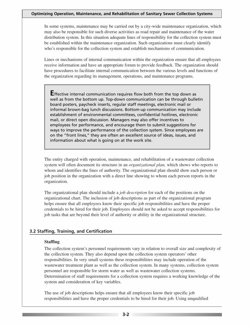
Effective internal communication requires flow both from the top down aswell as from the bottom up. Top-down communication can be through bulletinboard posters, paycheck inserts, regular staff meetings, electronic mail orinformal brown-bag lunch discussions. Bottom-up communication may includeestablishment of environmental committees, confidential hotlines, electronicmail, or direct open discussion. Managers may also offer incentives toemployees for performance, and encourage them to submit suggestions forways to improve the performance of the collection system. Since employees areon the “front lines,” they are often an excellent source of ideas, issues, andinformation about what is going on at the work site.

personnel risks serious injury, jeopardizes equipment warranties if qualified personnel do not dorepairs, raises the potential that collection system components and private property may bedamaged, and increases the potential for SSOs.
Training
Collection system operators are exposed to numerous challenging conditions. Adequate training—especially safety training—is necessary for employees to meet these challenges. Personnelshould have the required training to effectively carry out the responsibilities of their position.
The commitment of management is essential for a training program to be effective. Resources inthe form of funding must be invested in the program for it to be productive. An organization withuntrained or poorly trained collection system operators runs significantly more risk for accidentsand injuries and of experiencing non-compliance in the collection system and future costlycorrective actions (such as a sewer collapse).
New employees should be trained on how to perform standard procedures, coordinate with otherpublic works and private utility crews, operate equipment, and observe health and safetyprotection requirements.
Informal on-the-job training of new employees often allows improper procedures and mistakenassumptions to be passed on. This type of initiation also places too much emphasis on “what wedo” and not enough emphasis on “why we do what we do,” so that employees don’t have enoughinformation to respond to problems they encounter as they are performing their tasks. A formalorientation/training program addressing wastewater collection system operation and maintenanceshould be developed for all new employees.
The training program should identify the types of training required and offered. Types of trainingvary, but may include general environmental awareness training, training related to specificequipment, training on policies and procedures, safety training, and training on conductingoperation and maintenance activities.
The collection system agency or organization should routinely assess the effectiveness of trainingthrough periodic testing, drills, demonstrations, or informal reviews, and improve trainingprograms based on these assessments.
Employee participation in the training program should be mandatory and tracked. Informationthat should be tracked for each employee includes:
• Employee identification and title.
• Employee certification and licenses.
• Classes attended.
• Test results, if applicable.
• Continuing education credits awarded.
Lastly, collection system operators and their activities are the most visible segment of theorganization. Operators project a public image for their utilities on city and town streets. For thisreason, personnel need to be trained in what to expect in public situations and how to dealeffectively with the public and present a good image for the municipality.
Chapter 3: OPTIMIZING ADMINISTRATIVE AND MANAGERIAL FUNCTIONS
3-3
Certification
There are many benefits to implementing employee certification requirements, includingprotection of the public’s investment in facilities and infrastructure, employee pride, andrecognition. Certification assures that facilities and equipment are operated and maintained byqualified operators who possess a certain level of competence. Certification gives collectionsystem operators an upgraded image and provides a measurable goal that operators can strive forby preparing themselves to do a better job. Passing a certification exam is often recognized by anincrease in salary and other employee benefits.
3.3 Budgets
Although an adequate budget is not a guarantee of a well-run collection system, an inadequatebudget will make this achievement difficult. Funding has significant impacts on staff and theirability to do their job. Funding can come from a variety of sources, including user fees orappropriations from the State or local government.
A key element of the operation budget program is the tracking of costs in order to have accuraterecords each time the annual operating budget is developed. Having an annual baseline providesdocumentation for future budget considerations and provides justification for future rateincreases. Collection system management should be aware of the procedures for calculating userrates and for recommending and making user rate changes as often as necessary to manage,operate and maintain the efficiency and effectiveness of the utility.
The major categories of operating costs are labor, utilities, and supplies. Cost accounting forthese categories should include information on unit costs, total costs, and the amount/quantitiesused.
The cost of preventive and corrective maintenance and major collection system repairs andalterations are major items in the yearly operating budget and capital improvement program(CIP). The utility should keep an adequate record of all maintenance costs, both in-house andcontracted, plus the costs from spare parts. This will assist in the preparation of the next year’sbudget.
A capital improvement fund must be part of the organization’s budget in order to keep thesystem operating properly in the future. Capital planning starts with a look at changes in thecommunity. Where are the areas of growth in the community? Where are the areas of decline,and what are the anticipated changes in industry within the community? After identifying thechanging needs in the community, the existing utility structure should be examined and weakspots identified. Expected capital improvements within the next year, two years, five years, andten years should also be identified. Once all of this information has been compiled, it can beprioritized and a timetable developed for improving each of the areas identified.
3.4 Asset Management
Asset management, created to foster more efficient financial and physical resource investmentsand to prolong the life of the infrastructure system components, can be defined as managinginfrastructure capital assets to minimize the total cost of owning and operating them whiledelivering the service level customers desire.
Optimizing Operation, Maintenance, and Rehabilitation of Sanitary Sewer Collection Systems
3-4

Use of asset management procedures will help protect wastewater collection systems and extendfinancial resources by:
• Making sure components are protected from premature failure through proper operationand preventive and predictive maintenance.
• Facilitating proactive capital improvement planning and implementation over longercycles to reduce annual and overall costs.
• Reducing the need for expansions and additions through demand management.
• Reducing the cost of new or planned investments through economic evaluation of optionsusing life-cycle costing and value engineering.
• Focusing attention on results and by clearly defining responsibility, accountability, andreporting requirements within the organization.
• Maintaining stable and justifiable user rates.
An emphasis on asset management can better ensure that the key components of a strategicbusiness plan, such as level of service definition, rate setting, budgeting, financing, and valueengineering are taken into consideration.
Asset management and environmental management systems (EMSs) have valuable attributes andcan complement each other, but they are not the same. The asset management approach helpsutility owners optimize maintenance and replacement cycles to cost-effectively ensure that thesewer collection system runs smoothly and to accurately predict capital funding needs over along planning horizon. It assumes that the utility owner has identified its environmentalcompliance goals and has incorporated them into the planning process. By contrast, EMSs aredesigned to help an organization identify and manage a full range of environmental, publichealth, and safety issues—both regulated and unregulated (i.e., surface water, groundwater, airquality, noise, etc.) EMSs are designed to help integrate these issues into an overall system thatcan help continually improve environmental performance and provide other important businessbenefits like reduced costs through energy and water conservation, reduced chemical usage,reduced risk of noncompliance, to name a few.
The key elements of asset management are:
• Level of service definition.
• Selection of performance goals.
• Information systems.
• Asset identification and valuation.
• Failure impact evaluation and risk management.
• Condition assessment.
• Rehabilitation and replacement planning.
• Capacity assessment and assurance.
• Maintenance analysis and planning.
• Financial management.
• Continuous improvement.
Chapter 3: OPTIMIZING ADMINISTRATIVE AND MANAGERIAL FUNCTIONS
3-5
3.4.1 Components of an Asset Management System
Level of Service Definition
A basic level of service definition for most collection systems will be to deliver reliablesewer collection services at a minimum cost, consistent with applicable environmental andhealth regulations. Examples include:
• Ensuring adequate system capacity for all service areas.
• Eliminating system bottlenecks due to pipe blockages or other system defects.
• Reducing peak flow volumes through inflow/infiltration (I/I) controls.
• Providing rapid and effective emergency response service.
• Minimizing cost and maximizing effectiveness of CMOM programs.
Performance Measurements
Performance measurements are specific indicators designed to assess whether level ofservice objectives are being met. Some examples of performance measurements:
• Annual performance goals for sewer system inspection, cleaning, maintenance,rehabilitation, and capital improvement.
• Correlating grease control education and enforcement measures with expectedreductions in the number, distribution, and severity of grease blockages.
• Correlating illegal connections (sump pumps, roof leaders, foundation drains, etc.)education with wet weather SSO’s.
• Establishing maximum hourly and monthly peak flow volumes.
• Establishing maximum emergency response time to emergency calls, trackingcustomer complaints and dealing with claims for private property restoration.
• Performing cost-benefit analysis of key completed activities, taking into accountexpected vs. actual outcome and budgeted vs. actual cost.
Information System
Each utility must analyze its information needs. Begin with an evaluation anddocumentation of existing information systems. The next step is to perform a side-by-sidecomparison between identified information needs and existing systems to reveal gaps. Aprioritized, phased plan is then developed to fill in the gaps.
For most utilities, information is most efficiently managed by use of asset managementsoftware programs that help organize the data, perform many standard analyses, andfacilitate planning, scheduling, and budgeting. These programs range in cost andcomplexity from affordable, simple applications to very complex, expensivesolutions–from several thousand dollars to several hundred thousand dollars.
A geographic information system (GIS) links database information to points on the map,which are primarily defined by manhole locations and their connecting sewer segments.The GIS can then be linked to the asset management system, sewer system modelapplications, and even billing systems.
Asset Identification and Capitalization
Asset identification is the process of identifying and numbering the primary components
Optimizing Operation, Maintenance, and Rehabilitation of Sanitary Sewer Collection Systems
3-6
in the sewer system. Once the components are assigned unique identifiers, the utility canuse a GIS to link information systems and aggregate data for financial, economic,technical and management use.
For instance, sewer main segments would be identified by location, length, material, size,slope, burial depth, beginning and ending manholes, and approximate or actual age. Thenumbering system used to assign unique identifiers to components should be based onmanholes, with the sewer segments numbered according to their relationship to thebeginning and ending manholes.
Map data should be verified with physical system inspection methods such as closed-circuit TV (CCTV), sonar/CCTV, static camera, or person-entry. Latitude/longitudecoordinates should be established or verified using global positioning surveying (GPS)techniques.
Complete sewer system inspection is an expensive and time-consuming undertaking thatmust be carefully planned and coordinated to support many aspects of the assetmanagement program. Many communities will need to prioritize and plan inspection overa period of years. Highest priority for inspection should be given to sewers that haveknown defects, have caused or contributed to SSOs or treatment plant violations, havenegatively impacted users, or have the potential to impact sensitive environmental ordrinking water sources.
Asset Capitalization
In general, the capitalized amount of an asset is defined as its acquisition cost (design,construction, land acquisition, etc.), plus capital improvements, minus accrueddepreciation. For collection system utilities, this valuation could be established at thesubsystem level—force mains, sewer mains, service laterals, manholes, etc. or at theoverall system level.
Failure Impact Evaluation and Risk Management
The potential impacts from sewer line failures should be assessed on a system-wide basis.The goal is to identify those areas of the system that will have the most impact if a failureoccurs, and focus asset management resources to minimize the risk.
Condition Assessment
Condition assessment is performed to identify assets that are underperforming, determinethe reason for the deficiency, predict when failure is likely to occur, and determine what cor-rective action is needed and when. The GASB 34 modified accounting option requires thatcondition assessment be based on an up-to-date inventory of assets. A condition level mea-surement scale should be used, and a minimum acceptable condition should be establishedand incorporated into the administrative rules governing the operation of the collection sys-tem (municipal ordinance, state or county statute, etc.) Whatever benchmarks are chosen,they should refer primarily to the physical condition of the system and its components.
Components found to be in poor condition, or with severe defects and high failure impactratings, should be addressed as soon as possible after they are discovered. Less severedefects can be prioritized for more frequent inspection or cleaning, repair, rehabilitation,or replacement.
Chapter 3: OPTIMIZING ADMINISTRATIVE AND MANAGERIAL FUNCTIONS
3-7
Rehabilitation and Replacement Planning
Proactive rehabilitation and replacement planning provides the best opportunity for capitalcost savings. By rehabilitating or replacing sewers and other components before they fail,the utility automatically avoids costs such as emergency contractor fees, staff overtime,unplanned repairs, and SSO cleanup costs. Additional savings can be achieved throughcoordination of sewer construction with other construction projects, replacing longersegments, and phasing construction over a period of years.
Optimizing Operation, Maintenance, and Rehabilitation of Sanitary Sewer Collection Systems
3-8
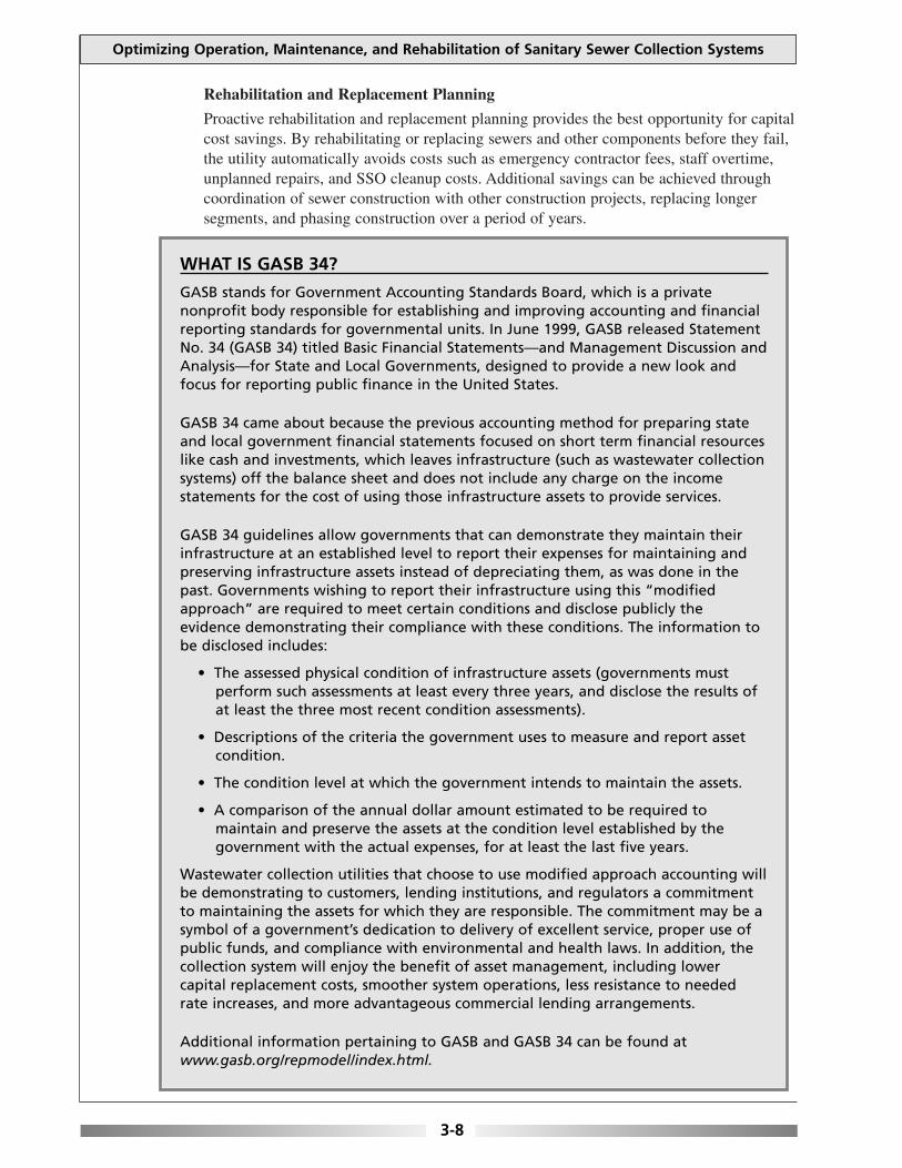
WHAT IS GASB 34?
GASB stands for Government Accounting Standards Board, which is a privatenonprofit body responsible for establishing and improving accounting and financialreporting standards for governmental units. In June 1999, GASB released StatementNo. 34 (GASB 34) titled Basic Financial Statements—and Management Discussion andAnalysis—for State and Local Governments, designed to provide a new look andfocus for reporting public finance in the United States.
GASB 34 came about because the previous accounting method for preparing stateand local government financial statements focused on short term financial resourceslike cash and investments, which leaves infrastructure (such as wastewater collectionsystems) off the balance sheet and does not include any charge on the incomestatements for the cost of using those infrastructure assets to provide services.
GASB 34 guidelines allow governments that can demonstrate they maintain theirinfrastructure at an established level to report their expenses for maintaining andpreserving infrastructure assets instead of depreciating them, as was done in thepast. Governments wishing to report their infrastructure using this “modifiedapproach” are required to meet certain conditions and disclose publicly theevidence demonstrating their compliance with these conditions. The information tobe disclosed includes:
• The assessed physical condition of infrastructure assets (governments mustperform such assessments at least every three years, and disclose the results ofat least the three most recent condition assessments).
• Descriptions of the criteria the government uses to measure and report assetcondition.
• The condition level at which the government intends to maintain the assets.
• A comparison of the annual dollar amount estimated to be required tomaintain and preserve the assets at the condition level established by thegovernment with the actual expenses, for at least the last five years.
Wastewater collection utilities that choose to use modified approach accounting willbe demonstrating to customers, lending institutions, and regulators a commitmentto maintaining the assets for which they are responsible. The commitment may be asymbol of a government’s dedication to delivery of excellent service, proper use ofpublic funds, and compliance with environmental and health laws. In addition, thecollection system will enjoy the benefit of asset management, including lowercapital replacement costs, smoother system operations, less resistance to neededrate increases, and more advantageous commercial lending arrangements.
Additional information pertaining to GASB and GASB 34 can be found atwww.gasb.org/repmodel/index.html.

Capacity Assurance Planning
Capacity planning should be based on:
• Review of existing capacity constraints.
• Analysis of predicted demand for sewer service based on regional growth patterns.
• Identification of current and future capacity shortfalls.
• Identification and evaluation of alternatives for correcting the deficiencies.
Chapter 3: OPTIMIZING ADMINISTRATIVE AND MANAGERIAL FUNCTIONS
3-9
Benefits of Water Conservation and Efficiency
Collection systems operating at or near capacity can benefit from a program toencourage water conservation and efficiency. Water conservation and efficiencyhave an effect on how much wastewater is produced, thereby having a directimpact on the performance and life of a wastewater system. A reduction in theamount of wastewater generated due to improved conservation and efficiencypractices that target both the engineering and behavioral practices of thecommunity can be extremely useful to any wastewater system. However, theseconservation and efficiency programs should be tailored to the local conditions,taking into account various factors to determine the proper mix of efficiencymeasures and the priority of the program.
One way to reduce wastewater flows is to adopt engineering practices based onmodifications in plumbing, fixtures, or water supply operating procedures onthe customer’s side of the meter. Installing water-saving devices and repairingleaky pipes, faucets, and toilets could save thousands of gallons of water perperson per year, and greatly reduce the amount of wastewater entering thecollection system and requiring treatment.
Community-wide water conservation and efficiency programs can also includewater use surveys, plumbing fixture retrofit kits, rebate or incentive programsfor low-flow toilet and appliance replacement, and informational/educationalprograms.
Additional information on the benefits of a water conservation and efficiencyprogram and guidance on establishing a program are available from thefollowing sources:
Water Efficiency Fact Sheet—A Technical Overview. National Small FlowsClearinghouse. No. WWFSOM33. 1998. Available at: www.nsfc.wvu.edu
On the web:American Water Works Association—Water Efficiency Clearinghouse.
Available at: www.waterwiser.org
EPA’s Water Use Efficiency ProgramAvailable at: www.epa.gov/owm/water-efficiency/index.htm
Saving Water Partnership, a group of local utilities in Seattle and King County,Washington area that fund water conservation programs.
Available at: www.savingwater.org

Maintenance Analysis and Planning
The asset management goal is to maximize planned maintenance and minimize unplannedmaintenance. Planning should be performed annually and updated throughout the year asneeded to address changing conditions. Maintenance activities are either planned (i.e.,inspecting all major lines in the system every 15 years, cleaning all major lines on arotating basis every five years) or unplanned (i.e., defect repair, emergency blockageremoval).
Field crews should be integrally involved with maintenance planning. As the maintenanceprogram proceeds, field staff should be encouraged to provide feedback on whichstrategies are working and which are not, to allow mid-course corrections if necessary.
Financial Management
The goal of sewer system financial management is to identify how much money will beneeded to meet level of service goals and maintain the system at or above the identifiedminimum condition, forecast when the money will be needed, and use the information toset user fees, other revenues, and debt financing.
Financial forecasting should be performed over a period of five to 10 years, and should beupdated annually. The annual estimate of the cost to maintain the system is included in theutility's annual financial report, along with a full accounting of cash flows, debt financing,and financial reserve activity and capital improvements program.
The high up-front costs of capital acquisition often dominate the capital improvementplanning process. It is, however, important to evaluate capital improvement alternativesrelative to the blend of capital and lifecycle costs and the expected useful life of the asset.Other lifecycle costs that may affect the cost of ownership include the risk of harm tohuman health or the environment, or the risk of private or public property damage in theevent of failure.
Continuous Improvement
Continuous improvement processes are based on periodic review of systems againstperformance measures to identify any shortfalls. Performance measures can be related tolevel of service goals, condition maintenance goals, or asset management system goals.
Alternatively, if an operational or capital improvement program is completed and theexpected performance improvement is not realized, further analysis may be needed toidentify the most effective next actions.
3.5 Safety
The development of a safety program is a necessity for any collection system agency. Thepurpose of the program is to define the principles under which the work is to be accomplished, tomake employees aware of safe working procedures, and to establish and enforce specificregulations and procedures. The program should be in writing (e.g., written procedures, policiesand training courses) and training should be well documented. Safety training cuts across all jobdescriptions and should emphasize the need to recognize and address hazardous situations.
Optimizing Operation, Maintenance, and Rehabilitation of Sanitary Sewer Collection Systems
3-10

The safety program should explicitly state the organization’s safety policy. The safety policystatement should be prepared by the top management of the collection system agency with theclose consultation of the agency’s safety officer/safety consultant, and select staff, since itspurpose is to let employees know that the safety program has the full support of the agency andits management.
The safety policy should:
• Define the goals and objectives of the program.
• Identify the person’s responsibilities for each element of the program.
• Affirm management’s intent to enforce safety regulations.
• Describe the disciplinary actions that will be taken to enforce safe work practices.
Within the safety program, management has the responsibility to:
• Formulate a written safety policy.
• Provide a safe workplace.
• Set achievable safety goals.
• Provide adequate training.
• Delegate authority to ensure that the program is properly implemented.
The manager/superintendent is the key to any safety program. Implementation and enforcementof the program is the responsibility of the manager. The manager/superintendent should:
• Ensure that all employees are trained and periodically retrained in proper safe workpractices and safety equipment.
• Ensure that proper safety practices are implemented and continued as long as the policy isin effect.
• Provide adequate safety equipment.
• Investigate all accidents and injuries to determine their cause.
• Institute corrective measures where unsafe conditions or work methods exist.
• Ensure that equipment, tools, and the work area are maintained to comply withestablished safety standards.
The collection system operators are the direct beneficiaries of a safety program. The operatorsshare the responsibility to:
• Observe prescribed work procedures with respect to personal safety and that of their co-workers.
• Report any detected hazard to a manager immediately.
• Report all accidents, even those that cause minor injuries.
• Report near-miss accidents so that hazards can be removed or procedures changed toavoid problems in the future.
• Correctly use all protective devices and safety equipment supplied to reduce thepossibility of injury.
Chapter 3: OPTIMIZING ADMINISTRATIVE AND MANAGERIAL FUNCTIONS
3-11

3.6 Security
As has already been discussed, the wastewater collection system represents a sizeable investmentby the community, so protecting it is a critical part of managing the system. Collection systemsmay be vulnerable to a wide variety of threats that can affect operations including naturaldisasters, operator errors, vandalism, and even terrorism. By adequately preparing, thecommunity’s investment, public health, environment, and other assets that rely on the systemwill be protected.
It is important to reassess the vulnerability of the collection system on a regular basis.Preparedness is not an end point, but a goal that can be achieved only through continued effortsto assess and improve the overall security of the system.
3.6.1 Securing Information
Records, maps, and other information should be stored in a secure location when not inuse. Utilities should make back-up copies of all data and sensitive documents on a regularbasis. Back-up material should be stored in a secure offsite location. Decision makersneed to address how sensitive documents (e.g., schematics, maps, and plans andspecifications) will be distributed for construction projects or other uses, and how theywill be recorded and recovered after use. Measures to safeguard documents used bybidders for new projects needs to be considered as well.
All computer access should be password protected and passwords should be changedperiodically and (as needed) following employee turnover. When possible, each individualshould have a unique password that they do not share with others.
Supervisory control and data acquisition (SCADA) systems are computer-monitoredalarm, response, control, and data acquisition systems used by collection system operatorsto remotely monitor and adjust the operation of equipment in the system. SCADA systemscan be vulnerable to potential intruders. The most direct approach to evaluatevulnerabilities is penetration testing, which can detect vulnerability and security breachesthat could be used to attack and penetrate the entire SCADA system. Hardening is theprocess of making the system less vulnerable through equipment upgrades, redundancy ofcomponents, etc. If you have a SCADA system, consider operating it on a system withoutinternet access to reduce the chance of unauthorized access.
3.6.2 Securing Facilities
Access to critical components of the collection system should be limited to authorizedpersonnel only, and staff need to understand and abide by the access policies that areestablished. Warning signs can be an effective means to deter unauthorized access. Checkregularly to be certain signs are present and legible.
Ideally, all facilities should have a security fence around the perimeter. The fence shouldbe walked periodically to check for breaches and maintenance needs. All windows anddoors should be locked. All gates should be locked with chains and a tamper-resistantpadlock. Other barriers, such as a concrete “jersey” barrier, can be considered to guardcertain critical components from accidental or intentional vehicle intrusion. Systemsshould ensure that all security measures comply with fire codes.
Optimizing Operation, Maintenance, and Rehabilitation of Sanitary Sewer Collection Systems
3-12

Suppliers and personnel from co-located organizations should be denied access to codesand/or keys. Change codes frequently, if possible. Entry into buildings should be under thedirect supervision of collection system personnel.
Utilities should establish a policy that an authorized person, designated by the collectionsystem agency, must accompany all deliveries. Verify the credentials of all deliverydrivers, preventing unauthorized personnel from having access to the collection system.
Utilities should keep a record of locks and associated keys, and to whom the keys havebeen assigned. This record will facilitate lock replacement and key management (e.g.,after employee turnover or loss of keys). Vehicle and building keys should be kept in alockbox when not in use. Have all keys stamped (engraved) “DO NOT DUPLICATE”.Electronic “swipe” card systems can be an effective way to regulate access.
Collection system vehicles should be locked when not in use or left unattended. Removeany critical information about the system before parking vehicles for the night or leavingthem unattended. Vehicles usually contain tools that could be used to access criticalcomponents of the collection system. Secure and account for tools daily.
Frequent and random patrolling of the above-ground portions and critical components ofthe collection system by utility staff may discourage potential tampering. It may also helpidentify problems that may have arisen since the previous patrol. Consider asking locallaw enforcement agencies to assist by conducting patrols of the collection system. Advisethem of your critical components and explain why they are important. Watchful neighborscan be very helpful to a security program. Make sure they know who to call in the eventof an emergency or suspicious activity.
When assessing the area around your collection system’s critical components, look forobjects that could be used to gain entry (e.g., large rocks, cement blocks, pieces of wood,ladders, valve keys, and other tools) and remove them if possible.
Tamper-resistant bolts or other methods may be used to secure manhole covers to rims.Lastly, protection of the collection system must be considered and included in theEmergency Response Plan.
3.6.3 Employees
Personnel should be trained and knowledgeable about security issues associated with thecollection system, know what to look for, and know how to report any suspicious events oractivities. Periodic meetings of authorized personnel should be held to discuss security issues.
Former or disgruntled employees have knowledge of the operation of the collectionsystem and could have both the intent and physical capability to harm the system and itsrelated assets. Requiring employees who will no longer be working at the collectionsystem agency to turn in their identification, keys, and access codes will help limit thesetypes of potential security breaches.
Chapter 3: OPTIMIZING ADMINISTRATIVE AND MANAGERIAL FUNCTIONS
3-13
3.7 Emergency Response Plans
The collection system agency should have in place a comprehensive plan for dealing with bothroutine and catastrophic emergencies. Routine emergencies include such situations asoverflowing manholes, backups into homes, line breaks, localized electrical failure, and pumpstation outages. Catastrophic emergencies include floods, tornados, earthquakes and other naturalevents; serious chemical spills; widespread electrical failure. Ideally, this plan is written,reviewed and adjusted accordingly over time.
The emergency preparedness and response procedures may be contained in the authority’s O & M manual, or may be reflected in the descriptions of equipment and unit operations.However, operators looking for information on emergency procedures can find it more easily in astand-alone document than when it’s combined with other information in the O & M manual
The plan should utilize the most up-to-date information on the collection system. A structuredanalysis, also called a risk assessment or vulnerability assessment, should be made of thecollection system, treatment plant, and the community. The assessment should identify areaswhere the collection system is vulnerable to failure and determine the effect and relative severityto collection systems operations, equipment, public safety and health of such a failure. Theassessment should concentrate on such factors as topography, weather, sewer system size, andother site-specific factors, which reflect the unique characteristics of the system. Once the areasof vulnerability are known, the authority should have appropriate plans in place to ensurecollection system operations continue for the duration of the emergency.
The plans must clearly identify the steps staff should take in the event of emergency situations.They should include information on when it is appropriate to initiate and cease emergency opera-tions. The plans should be very specific as to the collection system or repair equipment involved.Instructions should be available that explain how to operate equipment or systems during anemergency event when they are not functioning as intended but are not fully inoperable.
The plan should also include specific procedures for reporting events that result in an overflow orother non-compliance event to the appropriate authorities. Plans should specifically identifyemergency situations, responsibilities, actions to be taken, equipment to be used and sourcesthereof, and notification requirements including those involving regulatory authorities but alsoother local agencies such as the fire dept, ambulance, Local Emergency Planning Committee(LEPC), etc.
The plan should also contain a mechanism to keep the public/users notified of impacts to them,such as outages (including projected lengths of time), road closings, etc.
Typical components of an emergency program may include:
• General information regarding emergencies, such as telephone numbers of collectionsystem personnel, fire department, and ambulance.
• Identification of hazards (e.g., chlorine storage areas) and use of universal classificationsystem for hazards: Combustible material, flammable liquids, energized electrical circuits,and hazardous materials.
Optimizing Operation, Maintenance, and Rehabilitation of Sanitary Sewer Collection Systems
3-14

• Vulnerability analysis in which the collection system identifies the various types ofemergencies that could occur, such as natural or man-made disasters, power outages,equipment failures, vandalism, or other intentional acts of disruption.
• Emergency response procedures.
• Methods to reduce risk of emergencies.
• Responsibilities of staff and management.
An emergency response plan should provide a framework describing how the collection systemagency would notify the public, as well as other entities, of sanitary sewer overflows that mayimminently and substantially endanger human health as well as cause inconveniences. Theemergency response plans provision should not dictate the specific procedures or the specificinformation that would be provided through immediate notification. Rather, the emergencyresponse plan, in consultation with potentially affected entities, should establish a framework forcase-by-case notification, which depends on the nature of the overflow event and theresponsibilities of different local entities.
Given the complexities of immediate notification, it is critical to use the flexibility of a system-specific overflow emergency response plan to identify and clarify specific notificationresponsibilities and notification protocols. The emergency response plan should identifyappropriate authorities at the local, county, and/or State level to receive notification and identifythe roles and relationships of the collection system agency, public health authorities, and otherauthorities, including lines of communication and the identities of responsible officials.
A representative from management should be given the role of dealing with the media to addresspublic concerns. All other employees should refer inquiries to this designated spokesperson whencontacted by the media.
Collection system operators must be prepared to respond to routine emergencies with resourcesthat include appropriate procedures, spare parts, repair materials and equipment. Extraordinaryemergencies caused by natural events or manmade events tend to affect wider areas and otherutilities. These emergencies require greater time and resources due to the complexity ofcoordinating an effective response. Therefore, it is essential to have in place an effectiveemergency management plan to reduce the impact of extraordinary and routine emergencies.
Procedures for the emergency response plans should be understood and practiced by allpersonnel in order to ensure safety of the public, and the collection system personnel responding.Procedures need to be specific to the type of emergency that could occur. It is important to keepdetailed records of all past emergencies in order to constantly improve response training, and themethod and timing of future responses.
The ability to deal with emergencies depends on the knowledge and skill of the respondingcrews, in addition to availability of equipment. The crew needs to be able to rapidly diagnoseproblems in the field under stress, but they must also select the right equipment needed to correctthe problem. Crews therefore need immediate access to appropriate tools and equipment ifemergencies are to be dealt with as rapidly as possible. If resources are limited, considerationshould be given to contacting other departments or contracting with private industries to respondto some emergency situations, for example, those emergencies that would occur after normalhours of operation.
Chapter 3: OPTIMIZING ADMINISTRATIVE AND MANAGERIAL FUNCTIONS
3-15
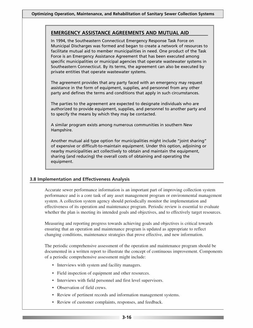
3.8 Implementation and Effectiveness Analysis
Accurate sewer performance information is an important part of improving collection systemperformance and is a core task of any asset management program or environmental managementsystem. A collection system agency should periodically monitor the implementation andeffectiveness of its operation and maintenance program. Periodic review is essential to evaluatewhether the plan is meeting its intended goals and objectives, and to effectively target resources.
Measuring and reporting progress towards achieving goals and objectives is critical towardsensuring that an operation and maintenance program is updated as appropriate to reflectchanging conditions, maintenance strategies that prove effective, and new information.
The periodic comprehensive assessment of the operation and maintenance program should bedocumented in a written report to illustrate the concept of continuous improvement. Componentsof a periodic comprehensive assessment might include:
• Interviews with system and facility managers.
• Field inspection of equipment and other resources.
• Interviews with field personnel and first level supervisors.
• Observation of field crews.
• Review of pertinent records and information management systems.
• Review of customer complaints, responses, and feedback.
Optimizing Operation, Maintenance, and Rehabilitation of Sanitary Sewer Collection Systems
3-16
EMERGENCY ASSISTANCE AGREEMENTS AND MUTUAL AID
In 1994, the Southeastern Connecticut Emergency Response Task Force onMunicipal Discharges was formed and began to create a network of resources tofacilitate mutual aid to member municipalities in need. One product of the TaskForce is an Emergency Assistance Agreement that has been executed amongspecific municipalities or municipal agencies that operate wastewater systems inSoutheastern Connecticut. By its terms, the agreement can also be executed byprivate entities that operate wastewater systems.
The agreement provides that any party faced with an emergency may requestassistance in the form of equipment, supplies, and personnel from any otherparty and defines the terms and conditions that apply in such circumstances.
The parties to the agreement are expected to designate individuals who areauthorized to provide equipment, supplies, and personnel to another party andto specify the means by which they may be contacted.
A similar program exists among numerous communities in southern NewHampshire.
Another mutual aid type option for municipalities might include “joint sharing”of expensive or difficult-to-maintain equipment. Under this option, adjoining ornearby municipalities act collectively to obtain and maintain the equipment,sharing (and reducing) the overall costs of obtaining and operating theequipment.
3.9 More Information
The American Public Works Association (APWA) has developed a guidance document forpreparing sewer overflow response plans titled Preparing Sewer Overflow Response Plans—AGuidebook for Local Governments, which is available (for a fee) from APWA. The APWAwebsite is www.apwa.net and their telephone number is 1-816-472-6100.
CHAPTER 3 REFERENCES
Collection Systems: Method for Evaluating and Improving Performance. California State University, Sacramento. 1998. Guide for Evaluating Capacity, Management, Operation, and Maintenance Programs for Sanitary Sewer Collection Systems
(DRAFT). U. S. Environmental Protection Agency. 2000. EPA No. 300-B-00-014.Utility Management. California State University, Sacramento. 1998.Operation and Maintenance of Wastewater Collection Systems (Volume I)- Fifth Edition California State University,
Sacramento. 1998.Operation and Maintenance of Wastewater Collection Systems (Volume II)- Fifth Edition California State University,
Sacramento. 1998.Asset Management for Sewer Collection Systems—Fact Sheet. U. S. Environmental Protection Agency. 2002.
Available at: www.epa.gov/npdes/pubs/assetmanagement.pdfDraft Notice of Proposed Rulemaking—NPDES Permit Requirements for Municipal Sanitary Sewer Collection Systems,
Municipal Satellite Collection Systems, and Sanitary Sewer Overflows. U. S. Environmental Protection Agency. January 4, 2001.
Protecting Your Communities Assets: A Guide for Small Wastewater Systems. National Environmental Training Center.November 2002. Available at: www.nesc.wvu.edu/netcsc/
Asset Based Vulnerability Checklist for Wastewater Utilities. Association of Metropolitan Sewerage Agencies. 2002. Available at: www.amsa-cleanwater.org/pubs/2002avcheck.pdf
Chapter 3: OPTIMIZING ADMINISTRATIVE AND MANAGERIAL FUNCTIONS
3-17

This page is intentionally blank.

Many municipalities have developed sewer use ordinances that improve performance and ensureproper maintenance of their wastewater collection system. The sewer use ordinance is a legaldocument that authorizes how the utility manages, operates and maintains its wastewater collectionsystem. Establishing or strengthening sewer use ordinances is a means of improving collection systemperformance.
Information for this chapter was primarily obtained from the following sources: Parsons, Inc.’sMunicipal Ordinance Considerations and Suggested Language to Help Control Sewer SystemOverflows (DRAFT), and the Water Environment Federation’s Control of Fats, Oil, and Grease(FOG)—Advanced Training Course.
4-1
4.1 Sewer Use Ordinances
Despite unique community conditions, the following is a list of general performance-affectingissues that most collection system agencies face. These include:
• The need to control infiltration, inflow, and exfiltration.
• The need to ensure proper design, installation, and inspection of sewer lines.
• The need to maintain all sewer line components, including those owned by private andpublic entities.
• The need to reduce the disposal of substances into the sewer line that can causeperformance problems.
• The need to find and eliminate illegal connections (sump pumps, roof leaders, foundationdrains, etc.).
Recognizing the health and legal problems that can result from sanitary sewer overflows andbackups, an increasing number of municipalities have enhanced their community’s sewer useordinance to address the collection system issues identified above.
A sewer use ordinance is a statute that is enacted by the legislative body of the municipalcorporation for public purposes in that jurisdiction. Municipalities adopt ordinances for public orgovernment purposes to facilitate the general administration and public welfare of the localcommunity, within delegated authority provided by the State constitution or State statutes.
A statute must be enacted by being formally introduced, voted upon favorably, and adopted bythe municipal legislative body (usually referred to as the city council, town council, villagecouncil, board of alderman, board of selectmen), and then signed into law by the municipalexecutive authority (e.g., mayor, city manager, commissioner, supervisor).
To be valid, a sewer use ordinance cannot conflict with the State’s constitution, general statutes,or the charter or other special legislative acts under which the municipal corporation operates.
Optimizing Operation, Maintenance, and Rehabilitation of Sanitary Sewer Collection Systems
CHAPTER 4
OPTIMIZING LEGAL AUTHORITY
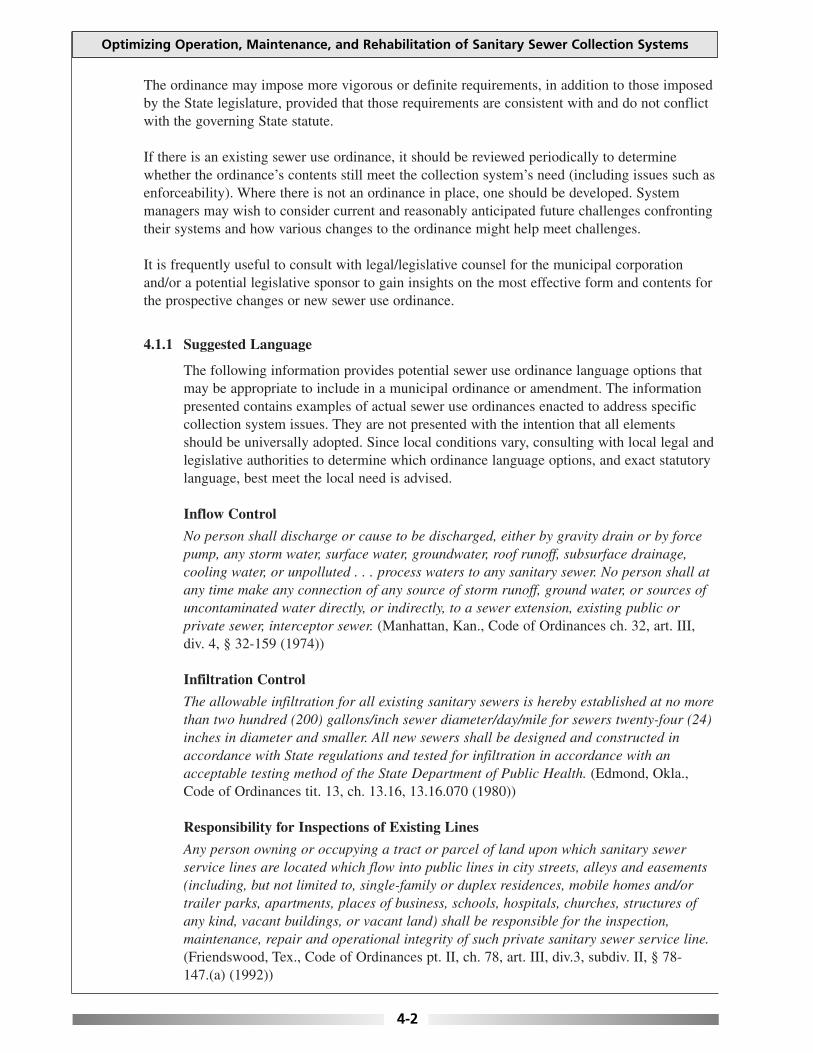
The ordinance may impose more vigorous or definite requirements, in addition to those imposedby the State legislature, provided that those requirements are consistent with and do not conflictwith the governing State statute.
If there is an existing sewer use ordinance, it should be reviewed periodically to determinewhether the ordinance’s contents still meet the collection system’s need (including issues such asenforceability). Where there is not an ordinance in place, one should be developed. Systemmanagers may wish to consider current and reasonably anticipated future challenges confrontingtheir systems and how various changes to the ordinance might help meet challenges.
It is frequently useful to consult with legal/legislative counsel for the municipal corporationand/or a potential legislative sponsor to gain insights on the most effective form and contents forthe prospective changes or new sewer use ordinance.
4.1.1 Suggested Language
The following information provides potential sewer use ordinance language options thatmay be appropriate to include in a municipal ordinance or amendment. The informationpresented contains examples of actual sewer use ordinances enacted to address specificcollection system issues. They are not presented with the intention that all elementsshould be universally adopted. Since local conditions vary, consulting with local legal andlegislative authorities to determine which ordinance language options, and exact statutorylanguage, best meet the local need is advised.
Inflow Control
No person shall discharge or cause to be discharged, either by gravity drain or by forcepump, any storm water, surface water, groundwater, roof runoff, subsurface drainage,cooling water, or unpolluted . . . process waters to any sanitary sewer. No person shall atany time make any connection of any source of storm runoff, ground water, or sources ofuncontaminated water directly, or indirectly, to a sewer extension, existing public orprivate sewer, interceptor sewer. (Manhattan, Kan., Code of Ordinances ch. 32, art. III,div. 4, § 32-159 (1974))
Infiltration Control
The allowable infiltration for all existing sanitary sewers is hereby established at no morethan two hundred (200) gallons/inch sewer diameter/day/mile for sewers twenty-four (24)inches in diameter and smaller. All new sewers shall be designed and constructed inaccordance with State regulations and tested for infiltration in accordance with anacceptable testing method of the State Department of Public Health. (Edmond, Okla.,Code of Ordinances tit. 13, ch. 13.16, 13.16.070 (1980))
Responsibility for Inspections of Existing Lines
Any person owning or occupying a tract or parcel of land upon which sanitary sewerservice lines are located which flow into public lines in city streets, alleys and easements(including, but not limited to, single-family or duplex residences, mobile homes and/ortrailer parks, apartments, places of business, schools, hospitals, churches, structures ofany kind, vacant buildings, or vacant land) shall be responsible for the inspection,maintenance, repair and operational integrity of such private sanitary sewer service line.(Friendswood, Tex., Code of Ordinances pt. II, ch. 78, art. III, div.3, subdiv. II, § 78-147.(a) (1992))
Optimizing Operation, Maintenance, and Rehabilitation of Sanitary Sewer Collection Systems
4-2

Time of Transfer Inspection Programs
Prior to the original connection, reconnection or transfer of water and/or sewer service toa tenant or property owner, the city may inspect or require the inspection of privatesanitary sewer service lines thereon for the purpose of determining the amount ofinfiltration and inflow into such lines, if any. Inspections shall be made or required when,based upon local infiltration and inflow conditions and experience, the director of publicworks has determined that such inspections are necessary to effectuate the purposes ofthis subdivision. Any conditions discovered in such line inspections causing or allowinginfiltration or inflow shall be repaired by the property owner or tenant, or agent thereof,prior to such original connection, reconnection or transfer of city water and/or sewerservice, as applicable. Where conditions have been discovered on existing private servicelines but for which no application for reconnection or transfer to city service has beensought, the property owner or tenant shall cause such repairs and maintenance to beperformed in accordance with sections 78-150 and 78-151. (Friendswood, Tex., Code ofOrdinances pt. II, ch. 78, art. III, div. 3, subdiv. II, § 78-148 (1992))
[Note: Time of transfer inspection programs are also effective for eliminating illicitconnections to the municipal stormwater collection system and identifying sources ofprivate infiltration.]
Inspection Programs – Power and Authority of Inspectors
The City shall be permitted to enter all properties for the purposes of inspection,observation, measurement, sampling and testing in accordance with the provisions of thischapter. (Edmond, Okla., Code of Ordinances tit. 13, ch. 13.16, 13.16.090 (1980))
Main, Trunk and Lateral Extensions – Permit Required to Connect with Sewers
Any project which is of sufficient discharge capacity and requires a state sewer extensionpermit pursuant to Massachusetts Sewer System Extension and Connection PermitProgram . . . must contribute to the reduction of infiltration and inflow to the public sewersystem. This may be in the form of a limited inflow/infiltration study, actual removal ofinflow/infiltration by pipeline rehabilitation, combined sewer separation, storm draininstallation, specific pipeline maintenance projects, a permit fee or other method asapproved by the sewer commission and department of public works.
Such inflow/infiltration reduction must establish an effective removal or planned removalof five times that volume proposed to that which is being introduced [by the sewer lineextension]. (Fall River, Mass., Revised Ordinances pt. II, ch. 74, art. III, div. 2, § 74-202(1988))
Private Line Specifications/Standards for Sewer Connections
The building sewer shall be connected into the public sewer at the property line by theCity, subject to fee outlined in section . . . of this article. Direct stub-ins through the wallof the sewer pipe shall not be permitted. Whenever possible, the connection shall be madeat the top of the pipe and smooth bends not exceeding forty-five (45) degrees shall be usedin the service pipe to prevent clogging. A neat workmanlike connection shall be made.(Alexandria, La., Code of Ordinances pt. II, ch. 27.5, art. I, § 27.5-4(l) (1980))
Inspection and Testing of New Sewers
4.2. Testing. The developer or contractor under the supervision of the city engineer willtest all sewers constructed for city acceptance as follows:
Chapter 4: OPTIMIZING LEGAL AUTHORITY
4-3
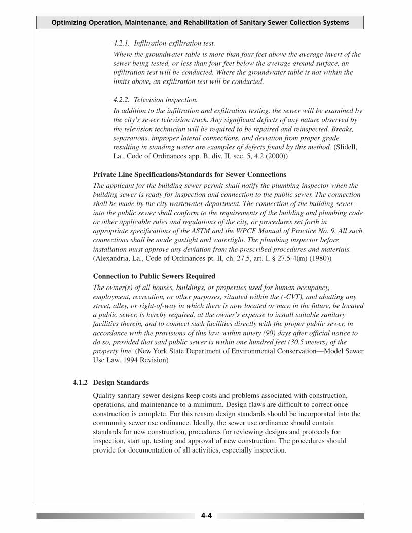
4.2.1. Infiltration-exfiltration test.
Where the groundwater table is more than four feet above the average invert of thesewer being tested, or less than four feet below the average ground surface, aninfiltration test will be conducted. Where the groundwater table is not within thelimits above, an exfiltration test will be conducted.
4.2.2. Television inspection.
In addition to the infiltration and exfiltration testing, the sewer will be examined bythe city’s sewer television truck. Any significant defects of any nature observed bythe television technician will be required to be repaired and reinspected. Breaks,separations, improper lateral connections, and deviation from proper graderesulting in standing water are examples of defects found by this method. (Slidell,La., Code of Ordinances app. B, div. II, sec. 5, 4.2 (2000))
Private Line Specifications/Standards for Sewer Connections
The applicant for the building sewer permit shall notify the plumbing inspector when thebuilding sewer is ready for inspection and connection to the public sewer. The connectionshall be made by the city wastewater department. The connection of the building sewerinto the public sewer shall conform to the requirements of the building and plumbing codeor other applicable rules and regulations of the city, or procedures set forth inappropriate specifications of the ASTM and the WPCF Manual of Practice No. 9. All suchconnections shall be made gastight and watertight. The plumbing inspector beforeinstallation must approve any deviation from the prescribed procedures and materials.(Alexandria, La., Code of Ordinances pt. II, ch. 27.5, art. I, § 27.5-4(m) (1980))
Connection to Public Sewers Required
The owner(s) of all houses, buildings, or properties used for human occupancy,employment, recreation, or other purposes, situated within the (-CVT), and abutting anystreet, alley, or right-of-way in which there is now located or may, in the future, be locateda public sewer, is hereby required, at the owner’s expense to install suitable sanitaryfacilities therein, and to connect such facilities directly with the proper public sewer, inaccordance with the provisions of this law, within ninety (90) days after official notice todo so, provided that said public sewer is within one hundred feet (30.5 meters) of theproperty line. (New York State Department of Environmental Conservation—Model SewerUse Law. 1994 Revision)
4.1.2 Design Standards
Quality sanitary sewer designs keep costs and problems associated with construction,operations, and maintenance to a minimum. Design flaws are difficult to correct onceconstruction is complete. For this reason design standards should be incorporated into thecommunity sewer use ordinance. Ideally, the sewer use ordinance should containstandards for new construction, procedures for reviewing designs and protocols forinspection, start up, testing and approval of new construction. The procedures shouldprovide for documentation of all activities, especially inspection.
Optimizing Operation, Maintenance, and Rehabilitation of Sanitary Sewer Collection Systems
4-4

4.2 Fats, Oil, and Grease Control
Fats, oil, and grease (FOG), primarily generated from restaurants and other institutional foodservice establishments, are major contributors to collection system blockages and overflows.Institutional food service establishments include, but are not limited to: mall food courts, foodmanufacturers, food packagers, restaurants, grocery stores, bakeries, lounges, hospitals, hotels,nursing homes, churches, and schools. Apartment and condominium complexes can also bemajor sources of FOG.
The effective management of FOG in sanitary sewer collection systems requires a strong legalfoundation. This foundation is often manifested in a municipality’s sewer use ordinance or aseparate FOG management ordinance. The management ordinance should be a complete outlineof the FOG management program. The program’s legal ordinance should refer to all of the basicrequirements of the program and leave the details of the implementation to rules and regulationsthat can be developed and changed, as needed. One common practice is to develop a FOG BestManagement Practices Manual and incorporate the manual by reference into the ordinance.
An effective grease control ordinance should establish the authority to:
• Establish who is regulated under the ordinance.
• Require grease interceptors, which are more effective than grease traps.
• Establish interceptor and/or trap design, construction, and inspection standards.
• Establish management, operation, and maintenance standards.
• Establish record keeping and reporting requirements.
• Regulate additives and alternative grease control devices.
• Issue individual/tailored permits or set a performance standard.
• Regulate grease haulers and establish fees.
• Regulate the proper disposal of FOG removed from grease traps and interceptors.
Establishing a local FOG management program is a resource-intensive undertaking. The resourcerequirements must be carefully considered when establishing a new program and municipalmanagement authorities should be made aware of the required resource commitment early in theplanning stages.
4.3 Private/Satellite Systems
A large number of public and private entities may own different pipes and other components ofthe entire municipal sanitary sewer collection system. In some situations, the municipality thatowns the collector sewers may not provide treatment of wastewater, but only convey itswastewater to a collection system that is owned and operated by a different municipal entity. Inaddition, private satellite collection systems are associated with a wide range of entities such astrailer parks, residential subdivisions, apartment complexes, commercial complexes such asshopping centers, industrial parks, college campuses, military facilities, hospitals, and prisons.
The collection system authority should have a comprehensive program, which addresses flowsfrom satellite communities. Satellite communities must not be allowed to contribute excessiveflows that cause or may contribute to overflows, flooding or non-compliance at the wastewater
Chapter 4: OPTIMIZING LEGAL AUTHORITY
4-5

treatment plant. Should any of these situations exist, it is not sufficient that the authority merelycharges the satellite community for the excess flow. The authority must be able to prohibit thecontribution of the excess flow.
4.4 Private Inflow Control
Inflow is a system-wide problem, which, if not addressed, can result in SSOs and backups intobuildings with significant adverse impacts to public health, welfare and the environment. Localprojects to identify and remove inflow sources from private property (Private Inflow) arehindered on several fronts.
It is often difficult to convince local elected officials that the public health and environmentalbenefits of private inflow removal outweigh the potential local public outcry often associatedwith inspection/enforcement on private property. Also, local Sewer Use Ordinances often lackeffective and employable measures for such enforcement.
There must be recognition that private inflow control is a complex issue and undertaking whichrequires a concerted and cooperative effort by a number of stakeholders, including homeowners,municipal officials and local agencies (including public works, building permits, plumbinginspector and board of health) and the State water pollution control agency.
Each wastewater system owner/operator should establish a Comprehensive Inflow RemovalProgram (Program). The Program should include a specific schedule for finding and redirectingall such sources unless the property owner can provide written documentation that the removal ofthe inflow source(s) will result in a severe financial burden. The Program should includeprocedures for periodic post-removal re-inspection to ensure that the inflow source(s) are notreconnected.
The wastewater system owner/operator should consider the following elements when designingits Program:
• Assess total system-wide costs to correct the problem and how corrective costs should beallocated.
• Inclusion of a one-time amnesty provision to get voluntary compliance.
• Consider financial assistance for building owners, such as providing homeowners withfree technical assistance to design a fix, and an interest free loan to implementimprovement.
• Assess local storm drainage system and its ability to provide a specific drain-connectionto the property line to allow homeowners to disconnect/reconnect private inflow sources.
• Coordinate private source implementation work with other municipal utility and/orroadway reconstruction activities (e.g., integrate work into larger construction projects tominimize costs and inconvenience).
• Coordinate activities with building and plumbing permit and inspection programs.
Any program for removal of private inflow must specifically include a process for directtechnical assistance to the property owner so that a viable and cost-effective alternative tocontinued connection to the wastewater system could be determined and implemented. It will be
Optimizing Operation, Maintenance, and Rehabilitation of Sanitary Sewer Collection Systems
4-6
difficult to implement a successful private inflow control program without the inclusion of suchtechnical assistance; the property owner needs to see that a feasible cost-effective option actuallyexists.
The program must include outreach and education components to alert homeowners to the factthat their private inflow source(s) is contributing to problems in the wastewater system that couldbe causing specific local system overflows into nearby water bodies and/or backups intobuildings, which could increase costs for all rate payers due to additional fees now and in thefuture.
Chapter 4: OPTIMIZING LEGAL AUTHORITY
4-7
WHAT ABOUT ILLICIT CONNECTIONS TO THE STORMWATER SYSTEM?
Municipal separate stormwater collection/conveyance systems frequently haveillegal wastewater connections (e.g. illicit connections), or other contaminateddischarges, which can pose significant threats to public health, welfare and theenvironment and severely restrict the beneficial uses of local waterways. Even arelatively small number of illicit connections can result in extensive degradationto the receiving water where the contaminated stormwater discharges.
Finding and eliminating illicit connections requires a series of concurrent andsequential actions that need to be carefully coordinated. Basic initial elementsinclude:
• Preparation of maps showing the locations and size of each stormwaterdischarge pipe, and if possible, the tributary drainage area.
• Visual observation of each of the stormwater discharge pipes to determinewhether the discharge is active during dry weather.
• Sampling of each of the active dry weather discharges from stormwateroutfalls to determine whether the discharge contains pollutants that wouldindicate illicit connections to the system.
• Development of a plan to identify and eliminate illegal sewer connectionsto the storm drains for areas where sampling results indicate the presenceof sanitary sewer flows.
• Update, as necessary, local sewer use ordinance and drain connectionregulations relative to preventing and eliminating illicit connections and/orcross connections (e.g. common manholes) between separate sewerage andstormwater systems.
Even though a successful illicit connection program can remove significantsources of contamination, it comes with a cost, both political and financial. Sincemost illicit connections are from private buildings, the program will require thedirect involvement of the public and will include such unpopular actions asaccess onto/into private property and often enforcement against individualbuilding owners. The financial impacts can also be significant.
A major goal of an illicit connection program must be to develop a costeffective, systematic and expeditious approach for identifying illegalconnections. Historically, illegal connection investigations are performed byvisually inspecting manholes starting at the lower reaches of the drainage area,near the outfall. Once a source of sanitary influence is identified, further
continued on page 4-8

4.5 More Information
The New York State Department of Environmental Conservation has a web page containinginformation about sewer use and water efficiency, as well as fats, oil, and grease control. Theweb page is available at: www.dec.state.ny.us/website/dow/bwcp/seweruse_mp.html.
The New York State Department of Environmental Conservation has developed a Model SewerUse Law that is intended to aid municipalities in developing or modifying their sewer use laws.The Model Sewer Use law is available at: www.dec.state.ny.us/website/dow/bwcp/seweruselaw.htm.
Additional information on successful fats, oil, and grease control programs is available from thefollowing organizations.
• North Carolina Department of Environment and Natural Resources, Division of PollutionPrevention and Environmental Assistance. Oil and Grease Documents available at:www.p2pays.org/food/main/oil.htm.
• Georgia Department of Natural Resources, Pollution Prevention Assistance Division. Fats,Oils, and Grease Initiative Documents available at:www.dnr.state.ga.us/p2ad/h_fog_initiative.html.
• Oregon Association of Clean Water Agencies. Fats, Oil, and Grease Best ManagementPractices Manual available at: www.oracwa.org/.
Optimizing Operation, Maintenance, and Rehabilitation of Sanitary Sewer Collection Systems
4-8
investigation of the drainage area would be suspended until the correction wasmade. After correction, follow-up inspections are performed. However, in manycases, there is still evidence of an upstream source of sanitary sewage andadditional investigation is required.
A methodology recently developed by the Boston Water and Sewer Commissionbegins by defining smaller sub-areas. Visual inspections of storm drain manholesare performed starting at the upper reaches of the drainage area and workingdownstream. The inspections are performed only after 48 hours of dry weather.If flow is observed in a manhole, the flow is tested in the field for ammonia andsurfactants using a field test kit. If no flow is observed, manholes at keyjunctions of the sub-drainage area are sandbagged for 48 hours to capturepossible intermittent flow from upstream storm drains. Any flow that iscaptured is inspected for evidence of contamination. If evidence ofcontamination exists, upstream buildings are dye tested to determine the sourceof the contamination. Manhole inspections downstream of the suspected sourceof contamination are suspended until all upstream sources are identified andcorrected. This way one can be almost assured that no illegal connections aremissed.
Additional information on illicit connections is available in a NEIWPCC guidancedocument titled Illicit Discharge Detection and Elimination Manual—AGuidebook for Municipalities, which can be downloaded at: www.neiwpcc.org.
WHAT ABOUT ILLICIT CONNECTIONS TO THE STORMWATER SYSTEM? continued from page 4-7

CHAPTER 4 REFERENCES
Municipal Ordinance Considerations and Suggested Language to Help Control Sewer System Overflows (DRAFT). Parsons, Inc.2002. EPA Contract No. 68-C-00-116, Work Assignment No. 1-03.
Control of Fats, Oil, and Grease (FOG)—Advanced Training Course. Water Environment Federation. July 2002.
Draft Notice of Proposed Rulemaking—NPDES Permit Requirements for Municipal Sanitary Sewer Collection Systems,Municipal Satellite Collection Systems, and Sanitary Sewer Overflows. U. S. Environmental Protection Agency. January 4,2001.
Guide for Evaluating Capacity, Management, Operation, and Maintenance Programs for Sanitary Sewer Collection Systems(DRAFT). U. S. Environmental Protection Agency. 2000. EPA No. 300-B-00-014.
Model Sewer Use Law—Incorporating Federal Pretreatment Language. New York State Department of EnvironmentalConservation. 1994 Revision.
Chapter 4: OPTIMIZING LEGAL AUTHORITY
4-9

This page is intentionally blank.
Collection system owners and operators must communicate effectively with municipal authorities,state and federal regulators, and the general public. Enhancing communication is an integral part ofoptimizing an operation and maintenance program.
Information for this chapter was primarily obtained from the following sources: U.S. EPA’s Guide forEvaluating Capacity, Management, Operation, and Maintenance Programs for Sanitary SewerCollection Systems (DRAFT) and Draft Notice of Proposed Rulemaking—NPDES PermitRequirements for Municipal Sanitary Sewer Collection Systems, Municipal Satellite CollectionSystems, and Sanitary Sewer Overflows; U.S. DHHS’s Communicating in a Crisis: RiskCommunication Guidelines for Public Officials; and the Maine Department of EnvironmentalProtection’s O&M Newsletter.
5-1
5.1 Working with the Public
Improving public awareness is important because the public can play a key role in improvingcollection system performance. The public is a key stakeholder that should have an opportunityto identify its concerns and expectations regarding the performance of collection systems andpotential public health and environmental risks.
The public does not always understand the benefits to be derived from collection system projectsthat may significantly raise their user rates and require temporary or permanent disruption.Public officials in turn may not be willing to counter public sentiment. Therefore, it is importantto engage and inform stakeholders early and maintain communication throughout the projectprocess.
Education is a vital tool that can eliminate potential barriers or opposition related to funding andsiting, provide support for the project, and reduce overall costs and disruptions. The public isusually more willing to pay for improvements it can see and understand.
The ability to establish constructive communication will be determined, in large part, by whetheran audience perceives you to be trustworthy and believable. Consider how they form theirjudgments and perceptions. Key factors in assessing trust and credibility are: empathy andcaring; competence and expertise; honesty and openness; and dedication and commitment.
5.1.1 Outreach
As stated earlier, building public support can be challenging. Holding an “Open House”can be an effective tool for building support, especially for larger system improvementprojects requiring public “buy-in.” The difference between an Open House and a publicmeeting is that a public meeting allows a project to be formally presented to all attendeesat once, while an Open House allows for more one-on-one interaction. An Open Housemay include relevant displays and handouts, but not formal presentations.
Optimizing Operation, Maintenance, and Rehabilitation of Sanitary Sewer Collection Systems
CHAPTER 5
EFFECTIVE COMMUNICATION

In addition to public meetings and open houses, there are a number of options availablefor presenting information to the public. These include direct mail, an insert into awater/sewer bill, publishing a notice in a local newspaper, or an addendum to otherexisting printed materials or notices such as signs or public health advisories posted atrecreation areas. The internet is likely to be an increasingly desirable medium for makinginformation available to the public. One option is to make the information available on themunicipality’s website.
Citizen advisory committees also work very well for community outreach. Thesecommittees include members of the community who volunteer to be a liaison between themunicipality, consulting engineers, and the public. The committee mechanism assures thepublic that their concerns are being addressed. This provides “buy-in” to the process andthe results.
5.1.2 Signage
An important form of outreach and communication involves the posting of chronicoverflow locations. Long-term posting might be appropriate in locations where releasesfrom the collection system are likely to re-occur, including emergency overflow structures,pump stations experiencing releases, and locations where remediation and rehabilitationrequire capital planning and construction over a long period of time.
Optimizing Operation, Maintenance, and Rehabilitation of Sanitary Sewer Collection Systems
5-2
FIVE RULES FOR BUILDING TRUST AND CREDIBILITY
1. Accept and involve the public as a partner. Work with and for the publicto inform, dispel misinformation and, to every degree possible, allay fearsand concerns.
2. Appreciate the public’s specific concerns. Statistics and probabilities don’tnecessarily answer all questions. Be sensitive to people’s concerns andworries on a human level. Do not overstate or dwell on negatives, but doempathize with the public and provide answers that respect theirhumanity.
3. Be honest and open. Once lost, trust and credibility are almost impossibleto regain. Never mislead the public by lying or failing to provideinformation that is important to their understanding of issues.
4. Work with other credible sources. Conflicts and disagreements amongorganizations and credible spokespersons create confusion and breeddistrust. Coordinate your information and communications efforts withthose of other legitimate parties.
5. Meet the needs of the media. Never refuse to work with the media. Themedia’s role is to inform the public, which will be done with or withoutyour assistance. Work with the media to ensure that the information theyare providing the public is as accurate and enlightening as possible.Designate a media coordinator and have other employees refer mediaquestions to this person.
Posting is also appropriate at locations where public exposure is more likely, such asswimming areas or parks. Posting at selected public places (e.g., a public informationcenter at a park, beach, or school) might be appropriate in cases where a relatively narrowsegment of the public is likely to be affected and can be reached via the public placesselected for display.
Posting locations should be identified in consultation with other affected entities, such aslocal, State, or tribal public health officials; and parks and recreation officials. Thisconsultation would occur as part of an integrated public outreach process.
Information provided in posted areas should include information such as the following:
• When exposure at this location could pose risks (e.g., “during and immediately afterheavy rains”).
• Where exposure may be a problem (e.g., “within 500 feet of this sign”).
• The nature of the problem (e.g., “this sewer may overflow and discharge rawsewage”).
• Why exposure should be avoided (“bacteria may cause illness”).
• How to avoid exposure (“do not swim or wade in this area”).
• Where to get more information.
• Request for public assistance in reporting discharges (“if you see a discharge fromthis pipe, please call [specified phone number]”).
The information would need to be targeted to the potentially affected population,including consideration for non-English-speaking individuals.
5.1.3 Alternative Dispute Resolution
Collection systems agencies and the communities they serve often have to deal withcomplicated projects and environmental decisions, which can hinge on difficult economic,environmental, and quality of life trade-offs. Debates about these issues can becomedivisive and lead to conflict, deadlock, or long and expensive legal proceedings.Alternative dispute resolution is used to describe a range of techniques that can helppeople settle their disputes without having to resort to litigation or to reach settlementmore efficiently within existing litigation proceedings. It is based on the concept thatpeople who are involved in a controversy are the ones best able to develop a reasonableand enduring solution because they know their own needs and interests.
Most alternative dispute resolution techniques involve the use of a neutral third party, whohelps orchestrate the process and ensures that it is implemented fairly and that everyone isheard and shares in the decision making process.
Constructive engagement, conflict assessment, facilitation, mediation, and consensusbuilding are all alternative dispute resolution techniques. These techniques offer theopportunity to improve communication among stakeholders and can promote betterrelations among groups that have been at odds. These techniques can save all stakeholderstime, money, and stress in the long run if used appropriately and conducted efficiently.
Chapter 5: EFFECTIVE COMMUNICATION
5-3
5.2 Working with Local Government
Often, resistance by chief financial officers and other upper management executives can be acritical barrier to implementing collection system improvement projects. The following outlineillustrates the kind of information that needs to be presented to successfully gain approval forsuch a project.
The information below is useful for effectively presenting a project to an authorizing or approvalauthority at an oversight board or local government meeting. In deciding who should be invitedto the meeting, consideration should be given to impact on budgets as well as on operations. It ismost important that all interested parties be fully informed before the meeting, so they can beprepared to participate. If your project gets approved, funding may have to come from otheractivities; those managers must be fully involved before your presentations, if you are to avoidhaving them oppose your project.
Besides gaining the cooperation of internal management, it might be wise to gain the support ofoutside parties, who might lend additional credibility to your proposal.
Your presentation to management must be tailored to the scope of the project and themanagement style of your leadership, and must be keyed to achieving a decision. The best idea isto make the individual in your management scheme that can ultimately approve the project thecenter of your presentation.
Your presentation should present all of the necessary information as concisely as possible. Donot waste valuable time with unimportant details. The more irrelevant details you furnish, thegreater the likelihood that someone will start to nit-pick. This may well divert the decision-maker’s attention from the true issues at hand.
5.2.1 Effective Project Presentation
The following outline suggests a format for presenting your project to management.
State the purpose of the presentation.
You want everyone attending your presentation to focus on the problem you will present,knowing that a decision will have to be made. If attendees think they are there for aninformation briefing, they may easily miss some of the points that will critically affect thedecision.
State the problem to be corrected.
What are the existing conditions that make it important that the project be considered?What costs are involved that can be reduced? How do existing conditions affectproduction, staffing, maintenance, and the bottom line?
Describe the scope of the project being proposed.
As briefly as possible and using a minimum of detail describe what the project willconsist of in terms of equipment, labor, time and cost to implement. This part of thepresentation will help the decision-maker and other key players get a fast understanding ofwhat you want to accomplish and how.
Optimizing Operation, Maintenance, and Rehabilitation of Sanitary Sewer Collection Systems
5-4
State the benefits to be achieved by implementing the project.
Using simple data summaries and graphical displays, explain how the project will cure theproblems you earlier laid out in discussing existing conditions and improvements to thebottom line. Emphasize reducing costs.
Clearly state the cost of the implementation.
Accurately state what it will cost to perform the project. You must examine all of thedirect costs involved, and also the indirect costs, as well as a percentage (e.g., 10 percent)for contingencies. Will there be additional costs?
Explain any effect the project will have on operations.
While this project is going on, will there be any adverse effect on operations? If so, howwill it be accommodated? Has the resultant cost of any such impact been included in theestimate of the cost of the implementation?
Present the effect on the budget.
Any significant new project will affect the budgeting process. If the project is beingsought for the current budget year, the effect is likely to be both large and widespread,having an effect on more than just one part of the organization. If the project is for afuture budget year, the planning may be simplified, but the effect may be felt throughoutthe organization. Unless a windfall of new revenue exists to fund the project, funding willhave to come from existing budget items that will have to be reduced. Advancecoordination with the likely targets of these budget transfers can help in getting approval.It may be necessary to clearly demonstrate a long-term benefit to be derived to convince asenior manager that he or she can accept a short-term loss of funds to support the project.
Much care should go into analyzing the Return on Investment (ROI), that is, the time overwhich the savings to be realized by the project equals the cost of implementing it. Theshorter the ROI, the more likely the project will be approved. This part of the presentationmay be a good time to compare graphically costs against time and present the expectedreturns to clearly illustrate the ROI. It is also a good time to restate any reduction in costper unit of production to be realized under the project.
A major barrier to project approval is often a lack of management awareness of realoperational costs. Collection/estimation of these costs, and simple graphical displays inyour presentation can help highlight the need for the project.
Provide a coordinated implementation plan.
The best plan, implemented poorly, can be a total failure. Coordination between andamong departments; realistic work schedules; accommodation for the unexpected; clearlystated, achievable milestones; and the assignment of a fully accountable project managerare essential to making the project a success. “What if” brainstorming should always beincluded in the planning. Under best conditions all of the affected activities should be inagreement on the plan before the decision briefing is presented. If such agreement is notpossible in advance, the plan should include an early milestone related to achieving thatlevel of agreed-to coordination. The timing for the project and each of the milestones arecritical to the decision process. The latest date a decision can be useful must be madeclear. Normally, this time estimate should allow management some time to consider
Chapter 5: EFFECTIVE COMMUNICATION
5-5

options and alternatives. However, it must be made clear that the reason the project isbeing sought is because a decision is needed, and it is needed by a specific date.
Summarize the project and ask for the decision.
Close the sale. Summarize the need for the project and timing, review the cost/benefitanalysis, lead the thought process to conclude the need for a decision, and ask that thedecision be made.
Provide a minimum of complicated details in the briefing itself. It is a good idea to haveon hand as much hard data detail as possible, in case it is requested. Spreadsheets andreports, process studies, cost data and analysis are all valuable backup to yourpresentation. However, avoid using these materials in the presentation itself to avoidconfusion. Any data that you provide should be in a prepared format, and it should not becluttered with ancillary, irrelevant data that may mislead or divert thinking. You shouldalways remember that the two most critical parameters in play during your presentationsare time and focus. Time is critical because the longer it takes to “make your case”—theless likely you are to get the decision you want. Focus is important because you do notwant the decision-maker to be distracted from the very specific goal of implementing yourproject.
The most important factor in gaining the approval you seek is coordinating in advancewith all of the affected managers and key players within your organization. If you can getthem to approve the concept informally in advance of your presentation to seniormanagement, a favorable decision will be much more easily achieved. In most cases, itwill be very difficult to get unanimous coordinated approval from all the players. Andremember that because of the competition for funding, one or more of the key players willsuffer some form of budget impact.
5.3 Communicating in a Crisis
A destabilized information environment (such as an ongoing large-scale SSO event) can make itvery important to give thought and consideration to what message needs to be delivered beforemaking any public comment—be it a 30-second statement to a news person or a 30-minute newsconference to a roomful of media representatives.
• Assess the environment into which you are introducing information. Gain a sense of thepublic’s general attitude toward the situation and tailor your presentation accordingly.
• Review your remarks to gauge the probable impact that your words will have on thesituation and adjust them as necessary.
• Understand your audience.
• Don’t speak unless you are comfortable doing so. Most communications mistakes aremade by those who are not prepared to speak but feel compelled to do so anyway. Ifconfronted with a demand for a quick answer, have the confidence to say, “I would like toanswer that question later.”
• Develop press releases to provide to the media.
People often fail to effectively communicate due to a lack of clear communications goals andkey messages to support them. Setting such goals and identifying support messages are decisions
Optimizing Operation, Maintenance, and Rehabilitation of Sanitary Sewer Collection Systems
5-6

that should be made prior to the issuing of any public comment and are especially important in acrisis.
Once goals and messages have been established, the challenge becomes one of delivery andensuring that messages are heard and goals are met.
Scientific information will be more useful to the audience and greater communication successwill be achieved if the information provided is relevant and easily understood. To help audiencesunderstand the issues, create well-targeted messages. Also be sure to use clear, non-technicallanguage to discuss risks and other specific information indicating the nature, form, severity, ormagnitude of the risk.
5.3.1 Communication Planning and Preparation
Much of the success of effective risk communications is predicated on the amount of workthat goes into planning and preparing for a crisis event.
Risk communication efforts should receive the same preparation as any other possibleemergency. Lists of contacts with addresses and phone numbers should be drawn up (andupdated regularly) and fact sheets and background materials should be prepared. The toolsand information needed to communicate fully and effectively when a crisis erupts have tobe readily accessible.
Guidance for Communication Planning and Preparation
• Form a risk communication team.
• Designate a team leader and assign responsibilities to teammembers.
• Develop a risk communication protocol.
- Who decides when a crisis exists, and what are each teammember’s responsibilities?
- Who speaks to the media/public on what subjects and at whosedirection?
• Develop and maintain lists.
- Primary contacts/experts for key offices and issue areas.
- Secondary contacts/experts for key offices and issue areas.
- Media lists.
• Identify information needs and develop appropriate fact sheets andbackground materials.
The more questions that can be anticipated and answered ahead of time in a fact sheet the better.This is especially true for information regarding high visibility public health issues such asoverflowing collection systems.
Chapter 5: EFFECTIVE COMMUNICATION
5-7
5.4 More Information
Additional information on public involvement and alternative dispute resolution is available fromthe U.S. EPA’s Office of Policy, Economics, and Innovation. Their website iswww.epa.gov/publicinvolvement.
The New England Water Environment Association (NEWEA) has developed a guidancedocument for working with the media titled Meet the Press—A Guide to Communicating with theMedia. The document can be downloaded from its website: www.newea.org.
CHAPTER 5 REFERENCES
Communicating in a Crisis: Risk Communication Guidelines for Public Officials. U.S. Department of Health and HumanServices. 2002.
Model Emergency Response Plan for Municipal Sewage Discharges. Loureiro Engineering Associates. 2002.Draft Notice of Proposed Rulemaking—NPDES Permit Requirements for Municipal Sanitary Sewer Collection Systems,
Municipal Satellite Collection Systems, and Sanitary Sewer Overflows. U. S. Environmental Protection Agency. January 4,2001.
Guide for Evaluating Capacity, Management, Operation, and Maintenance Programs for Sanitary Sewer Collection Systems(DRAFT). U. S. Environmental Protection Agency. 2000. EPA No. 300-B-00-014.
O&M Newsletter. Maine Department of Environmental Protection. May 2003.Preparing Sewer Overflow Response Plans—A Guidebook for Local Governments. American Public Works Association. January
1999.
Optimizing Operation, Maintenance, and Rehabilitation of Sanitary Sewer Collection Systems
5-8

Collection system owners and operators have a variety of technology-based resources available tothem. Effectively utilizing these resources will allow for operation and maintenance programenhancement.
Information for this chapter was primarily obtained from the following sources: U.S. EPA’s Guide forEvaluating Capacity, Management, Operation, and Maintenance Programs for Sanitary SewerCollection Systems (DRAFT) and Draft Notice of Proposed Rulemaking—NPDES PermitRequirements for Municipal Sanitary Sewer Collection Systems, Municipal Satellite CollectionSystems, and Sanitary Sewer Overflows and California State University, Sacramento’s CollectionSystems: Method for Evaluating and Improving Performance.
6-1
6.1 Benchmarking
Benchmarking is a process of gathering information on the productivity and performance ofother collection system agencies and then comparing actual information for an agency thatwishes to improve its level of production and performance. The concept became popular in theprivate sector in the 1970s and more recently it has been adopted by the public sector andprofessional associations as a method to develop new ideas, make fact-based decisions, andinitiate organizational change.
The benchmarking process enables a collection system agency to conduct an internal assessmentof its operation and maintenance program, compare its performance with the performance ofother similar agencies that are considered high-performing agencies, and attempt to improve itsperformance. Agencies can compare their system characteristics with other systems and alsotheir level of production, performance, and budget with other similar agencies. Subjects forcomparison include operation and maintenance data, finance, training and certification, safety,level of service, regulatory compliance, policies and procedures, and information management.
It should be noted, however, that there are very few areas where performance data from oneagency can be used directly by other agencies to produce the same performance results. This isdue to the wide variations in the collection system infrastructure such as age of the system, pipematerials, number of pump stations, and soil and groundwater conditions.
In spite of these difficulties, it is possible to establish performance indicators, which will provideinsight into the performance of the collection system and the effectiveness of the system’soperation and maintenance program. Data from multiple agencies can be plotted to develop a“range” of performance for various activities such as cleaning, stoppages, overflows, financialdata, number of staff, and safety. This information can be used to determine if performance fallswithin the desired range. If it does not, additional investigation should be carried out todetermine why agencies have different levels of performance.
Optimizing Operation, Maintenance, and Rehabilitation of Sanitary Sewer Collection Systems
CHAPTER 6
UTILIZING TECHNOLOGY EFFECTIVELY

6.1.1 Performance Indicators
Performance indicators should describe the performance of the collection system on thebasis of measurable objectives. Thus, the number of stoppages and the number ofcomplaints or service requests are important level of service performance indicators.Performance indicators should not be confused with production indicators. Typicalproduction indicators could be miles of sewers televised per year or miles of sewerscleaned per year.
Performance indicators can be used to:
1. Compare performance with similar agencies and then attempt to determinepotential areas for improvement.
2. Compare performance on an annual basis to identify performance trends within anagency.
3. Compare performance of subsystems within an agency.
If the results from comparison of performance indicators reveal that other similar agenciesare performing at a higher level, it could mean a need for more equipment, more crews,increased training, a better capital improvement program, or an increase in certain areas ofthe budget.
If the results from comparison of performance on an annual basis reveal either anincreasing or a decreasing level of performance, then the cause of the trend should beidentified. The comparison could reveal a decreasing trend caused by equipment that iswearing out and needs replacing, operators may be retiring and are not being replaced, ornew operators are not being trained due to budget restrictions. An increasing trend couldbe caused by a successful capital improvement program, or additional equipment andcrews, which could justify additional funds to continue improving performance.Comparisons should also consider other factors that could contribute to trends, such asextremes in weather patterns.
6.2 Management Information System
The foundation of a collection system agency’s management system is its managementinformation system. The ability of the authority to effectively manage its collection system isdirectly related to its ability to maintain and have access to the most up-to-date informationconcerning its facilities. Maintenance of this up-to-date information is an effort involving allmembers of the authority from the staff person answering the telephone to the operator in thestreet.
A satisfactory management information system should provide the authority with the ability to:
• Access information queries faster.
• Maintain preventive maintenance and inspection schedules.
• Provide budgetary justification.
• Track repairs and work orders.
• Organize capital replacement plans.
Optimizing Operation, Maintenance, and Rehabilitation of Sanitary Sewer Collection Systems
6-2

• Manage tools and equipment inventories.
• Print out purchase orders.
• Record customer service inquiries/complaints.
Collection systems agencies have been increasingly moving towards computer-based systems tomanage data. Only the very smallest systems still rely on paper data management systems.Computer-based Maintenance Management Systems (CMMSs) are designed to manage dataneeded to track the collection system’s O&M performance.
Global Positioning Systems (GPS) and Geographic Information Systems (GIS) are used in thefield to map and locate system components and, because of their computer-based compatibility,can easily be integrated with a CMMS. However, it is important to note that these computer-based systems can only be as accurate as the data that is being generated in the field.
Management information systems are critical to the collection system authority in that they helpensure appropriate staffing and budgeting, proper operation and maintenance, and compliancewith environmental and safety requirements. Regardless of the management information stylechosen, the collection system should have written instructions regarding the use of themanagement information systems. These procedures may include operating the system,upgrading the system, accessing data and information, and developing and printing reports.
6.3 Maps and GIS
The importance of maintaining accurate, up-to-date maps of the collection system cannot beoverestimated. Efficient collection system maintenance and repairs are not possible if mapping isnot adequate.
Collection system maps should have a numbering system, which uniquely identifies all manholesand sewer cleanouts. The system should be simple and easy to understand. Manholes and sewercleanouts should have permanently assigned numbers and never be renumbered. Maps shouldalso indicate the property served and reference its cleanout.
Sewer line maps should indicate the pipe diameter, type of pipe, the length between the centersof the up and downstream manholes, the direction of flow, location of manholes and servicewye’s including three (3) swing ties to known fixed objects (hydrants, telephone poles, etc.) pipeinvert elevations, slopes, pipe materials. The dimensions of easements and property lines shouldbe included on the maps. Other information to be included on maps is access and overflowpoints, storm drainage systems, a scale and a north arrow. All maps should have the date the mapwas drafted and the date of the last revision. The use of GPS to accurately measure the locationof collection system components is increasing.
GIS has made the mapping and map updating process considerably more efficient. GIS is acomputerized mapping program capable of combining mapping with detailed information aboutthe physical structures within the collection system as well as historical information includingvideo imaging of the pipe and manhole interiors.
It is important that there are specific procedures established for correction of errors and updatingmaps and drawings. Field personnel must be properly trained to recognize discrepancies between
Chapter 6: UTILIZING TECHNOLOGY EFFECTIVELY
6-3
field conditions and map data and to record changes necessary to correct the existing mappingsystem. The accuracy of the drawings used by field personnel and contractors is critical to properidentification of wastewater collection system components.
6.4 Flow Monitoring
Fundamental information about the collection system is obtained by flow monitoring, namelyhow much wastewater is conveyed through the system by pipes, pump stations and force mains.Flow monitoring will provide information on both dry and wet weather flows as well as areas ofthe collection system potentially affected by infiltration and inflow. Flow measurement may alsobe performed for billing purposes, to assess the need for new sewers in a certain area or tocalibrate a model. There are basically three techniques for monitoring flow rates: permanent,long-term monitoring; temporary monitoring; and instantaneous monitoring. Permanentinstallations are done at key points in the collection system such as the entry point of a satellitecollection system, pump stations, and key junctions. Temporary monitoring consists of flowmeters typically installed for 30-90 days. When the operator performs instantaneous flowmetering, one reading is taken and then it is removed.
A flow-monitoring plan should provide for routine inspection, service and calibration checks (asopposed to actual calibration). In some cases, the data is calibrated rather than the flow meter.Each meter should be checked on a predetermined schedule. Checks should include takingindependent water level (and ideally velocity readings), cleaning accumulated debris and siltfrom the flow meter area, downloading data (sometimes only once per month), and checking thedesiccant and battery state. Records of each inspection should be maintained.
6.5 Modeling
A model is a computer program that is capable of simulating the different flows within thecollection system. Modeling is a tool that may be used to assess the collection system’s capacityunder various flow scenarios. If a collection system is not experiencing any capacity relatedissues, i.e., overflows, bypasses, basement backups, street flooding, hydraulic overload at thetreatment plant, etc., then maintenance of a model may be optional for that system, althoughmost medium and large systems should maintain a model of the larger diameter portion of theirsystem. The use of a model is also effective for determining how system expansion andextension might effect overall operation. If any of the mentioned conditions are occurring, thenmaintenance of a model is essential to performing a capacity assessment in the problem areas.
Modeling is also useful in examining effects before and after rehabilitation. For example, modelscan be calibrated with “before” and “after” flow monitoring to estimate the effects of the repairs.
The model also needs to be properly calibrated. Improperly calibrated models may yield under-or over-estimations of flow. Calibration involves comparing actual flow measurements to thosegenerated by the model. For wet weather modeling, comparison of two to three storms isgenerally adequate.
Optimizing Operation, Maintenance, and Rehabilitation of Sanitary Sewer Collection Systems
6-4

6.6 More Information
Additional information on benchmarking is available from the following document:Optimization of Collection System Maintenance Frequencies and System Performance. AmericanSociety of Civil Engineers. February 1999. Available at: www.epa.gov/npdes/pubs/optimization-finalreport.pdf.
CHAPTER 6 REFERENCES
Collection Systems: Method for Evaluating and Improving Performance. California State University, Sacramento. 1998. Guide for Evaluating Capacity, Management, Operation, and Maintenance Programs for Sanitary Sewer Collection Systems
(DRAFT). U. S. Environmental Protection Agency. 2000. EPA No. 300-B-00-014.Draft Notice of Proposed Rulemaking—NPDES Permit Requirements for Municipal Sanitary Sewer Collection Systems,
Municipal Satellite Collection Systems, and Sanitary Sewer Overflows. U. S. Environmental Protection Agency. January 4,2001.
Chapter 6: UTILIZING TECHNOLOGY EFFECTIVELY
6-5

This page is intentionally blank.
A systematic operation, maintenance, and rehabilitation program is an essential element in themanagement of a wastewater collection system. Effective inspection, cleaning, and rehabilitation arekey processes for optimizing the proper functioning of a collection system.
Information for this chapter was primarily obtained from the following sources: U.S. EPA’s Guide forEvaluating Capacity, Management, Operation, and Maintenance Programs for Sanitary SewerCollection Systems (DRAFT) and Collection Systems O&M Fact Sheet Trenchless SewerRehabilitation, California State University’s Collection Systems: Method for Evaluating andImproving Performance and Operation and Maintenance of Wastewater Collection Systems (Volumes I& II).
7-1
7.1 Methods and Equipment
The following information outlines the methods and equipment frequently utilized to inspect andclean gravity collection systems and pumping stations. Frequent inspection and cleaning isessential for normal functioning and problem identification. Information is also presentedregarding spare parts and equipment necessary for effective operation.
7.1.1 Gravity Collection Systems
Physical Inspection
A physical inspection is vital to an O&M program. Without it, a maintenance programcannot be implemented in a systematic way since system problems cannot be quantified.Elements of a physical inspection program include visual and equipment-based techniquesthat use established industry methods of system evaluation. Physical inspections should beperformed on a regularly scheduled basis as a part of the preventive maintenance program.
The purpose of conducting inspections is to:
• Identify what is in the system (inventory).
• Identify the location of the system’s components.
• Determine the condition of the components (assessment).
• Prevent problems from developing.
Before acceptance of a newly constructed collection system, O&M personnel shouldconduct a physical inspection to verify the accuracy and completeness of the recorddrawings. Inspection before acceptance will also ensure that the new components are clearof construction debris and rocks.
Optimizing Operation, Maintenance, and Rehabilitation of Sanitary Sewer Collection Systems
CHAPTER 7
OPERATION, MAINTENANCE, AND REHABILITATION TECHNIQUES

Physical inspections are performed to accomplish the following goals:
• Identify defects in the system that can contribute to or cause backups, overflows, andbypasses.
• Identify chronic problem areas so maintenance can be planned and scheduled.
• Identify defects that if not fixed will result in a future failure.
• Determine the system needs for long-term replacement and rehabilitation.
• Develop a baseline for future comparison to determine rates of deterioration.
• Assist in setting and justifying realistic user charges.
Inspection provides a detailed inventory of the system that includes size, material,condition, line sags, joint types, elevations, slopes, location of manholes and pumpstations, location of building lateral connections and other system attributes that arenecessary for managing the entire O&M program.
Inspection data provide location information that allows more efficient O&M planningand scheduling and emergency response. During stoppages that involve overflows and/orbackups, valuable time is lost if location information is not available, increasing the riskof regulatory violations, property and environmental damage, and threats to public healthand safety.
Inspection provides the data necessary for managers to make informed decisions on allmaintenance, repair, and rehabilitation actions. This results in an O&M program that iseffective and efficient.
The primary methods of inspection and testing include the following:
• Air testing
• Vacuum testing
• Mandrel testing
• Smoke testing
• Dye water testing
• Closed-circuit television (CCTV)
• Visual (including lamping)
• Tape measurements
• Sonic Testing
Air testing and vacuum testing can test the integrity of the sewer main line, servicelaterals, and manholes. Mandrel testing will indicate whether the pipe has the properflushing and vertical and horizontal tolerances and is normally done in new pipe beforeplacing it in service. Smoke Testing indicates sources of inflow and sometimes infiltration.Dye water testing is used to determine sources of both I/I and permitted flow where dye isintroduced into the potential source and downstream manholes are observed to determineif and where it enters the system. Closed circuit television inspection will indicate pipeconditions including breaks and leaks, leaking and protruding laterals, root intrusions and
Optimizing Operation, Maintenance, and Rehabilitation of Sanitary Sewer Collection Systems
7-2
other blockages including the exact locations of all features and problems. The tapesprovide a visual history of the sewer for future reference and can be put on CDs forintegration into a GIS system. Visual testing using manhole access both from above andbelow ground, sometimes with the use of mirrors, gives an inexpensive indication ofblockages, pipe size, materials, and condition.
Visual and CCTV inspections will provide verification that manholes and cleanouts are onproper grade and accessible for future use. Accurate tie information and tapemeasurements also are used to physically locate manholes and cleanouts in case they arepaved over or are otherwise concealed. Inspection records should be updated regularly toinclude the exact locations of service taps and property lines so that they can be locatedwhen maintenance is required in the future. Sonar-based (sonic) equipment can be used tomeasure the internal cross-sectional profile of sewer systems. Sonar technology is alsovery useful for inspecting depressed sewers (inverted siphons), where the pipe iscontinually full of water under pressure.
Uniform coding of the system is a requirement to track all future inspection results andcompare current data to the baseline data. Each segment of sewer and each maintenancestructure should have its own unique identification. Numerous computer maintenancemanagement systems (CMMSs) are available that can manage the vast amount of sewersystem data generated from inspection programs, but they all rely on unique identificationof structures, main line segments, and laterals.
Any components of the system located along streams are particularly vulnerable to theeffects of rainstorms. Each sewer crossing of a stream should be inspected to be sure thesewer is not in danger of being broken. Also, the manholes on each side of the streamshould be checked to see that no excess flow is taking place, which would indicate aleaking sewer under the stream. Since these sewers are often in remote locations, they aresusceptible to vandalism and can overflow for long periods of time without detection.
Chapter 7: OPERATION, MAINTENANCE, AND REHABILITATION TECHNIQUES
7-3
Routine scheduled inspection of the entire wastewater collection system isrequired to verify the condition of the system so that blockages andoverflows can be prevented. Some agencies plan an inspection of the entiresystem over a period of time: for example, 20 percent of the entire system isscheduled for CCTV inspection each year. In the north, this is usuallyscheduled during early spring runoff and high groundwater conditions tolook for sources of I/I. Priorities may be established based on age of pipe, pipematerial, or other factors, which maximize the agency’s resources byidentifying areas with a higher probability of problems. Once the system hasbeen completely inspected and the condition quantified, scheduledinspections are prioritized based on need and availability of resources ratherthan simply re-inspecting the entire system using CCTV.
IF MANHOLES ARE ENTERED, PROPER TRAINING IN CONFINED SPACE ENTRYAND PROPER SAFETY HARNESS, TRIPOD, CALIBRATED GAS DETECTIONDEVICES, AND VENTILATION EQUIPMENT ARE A MUST.

Locking covers with adequate lid sealing is appropriate in these instances. Streamstabilization and sewer relocation can require long-range planning, design, permitting, andconstruction periods so it is important to identify problems as early as possible.
Cleaning
Stoppages in gravity sewers usually are caused either by structural defects or by anaccumulation of material in the pipe. Accumulated material can include fats, oil, grease,sediment, or other materials. Certain structural defects, such as protruding taps, may catchdebris, which then causes a further buildup of solids that will eventually block the sewer.Root intrusion through structural defects is a major contributor to blockages. Repair orelimination of any defects that contribute to a buildup of material in the pipe should beevaluated as part of a rehabilitation program since the defects will always be amaintenance problem.
Mechanical and hydraulic cleaning of sewers is a cost-effective method of removingmaterial that interferes with the proper operation of the sewer. The objective is to removeall material clinging to the interior surface of the pipe so that the sewer pipe can carry fullpipe flow without any restrictions that might result in blockages due to reduced pipecapacity.
Sewer cleaning should be scheduled on a regular cycle: for example, 100 percent of thepipes are cleaned every 1, 3, or 5 years. However, unless the cleaning schedule is adjustedto take into account the actual conditions in various parts of the collection systempipelines, routine cleaning can result in over-maintenance of the system. In mostcollection systems, some sections do not require frequent cleaning while other sectionsmay require cleaning on a more frequent basis, such as monthly, if they are susceptible toblockages. Information from the inspection program should be used to help identifychronic problem areas in the gravity sewer system and related structures in the wastewatercollection system, quantify defects and problem areas, and develop a preventivemaintenance sewer cleaning program based on actual conditions in a particular wastewatercollection system.
Cleaning is either scheduled or unscheduled. Scheduled cleaning is proactive in thatcleaning is done on a preventive basis to remove material prior to a stoppage occurring.Preventive cleaning activities can be supplemented by additional cleaning on an as-neededbasis in cases where predictive information such as previous history, inspection data, pipeage and material, slope, or other information indicates a need for more frequent cleaning.
Scheduled cleaning is usually coordinated with planned CCTV since televising requires aclean pipe for access and visually provides a much better picture of conditions.
Unscheduled cleaning is usually the result of a reported stoppage and is therefore reactive.When reactive maintenance is the primary form of maintenance (that is, waiting until afailure occurs before performing maintenance), it will always result in poor system perfor-mance, especially as the system ages. Normally, this type of cleaning is done on an emer-gency basis to clear a stoppage, restore pipe capacity to full flow, and relieve asurcharging situation in the sewer that has caused a backup into homes and/or an over-flow.
Optimizing Operation, Maintenance, and Rehabilitation of Sanitary Sewer Collection Systems
7-4
Various hydraulic and mechanical methods are available for main line sewer cleaning.Hydraulic cleaning methods include equipment that uses water and water velocity to cleanthe invert and walls of the sewer pipe. Mechanical cleaning methods use equipment tophysically remove the material from the walls and invert of the sewer pipe.
A. Hydraulic Cleaning
High-Velocity Cleaners
High-velocity cleaners are very efficient machines that provide the most flexibilitywith the least personnel required. A high-pressure stream of water is aimed at thesurface to be cleaned.
High-velocity cleaners can either be truck mounted or trailer mounted; in either case,they are designed as self-contained units for maximum efficiency.
All tools required to route traffic, remove manhole covers, and for safety of the jobsite are carried on the truck, as are the various nozzles and hoses required for properoperation.
The removal of debris from the sewer usually requires two operators on the normalhigh-velocity machine, but some agencies operate with a one-person crew in certainsituations. Under these circumstances, additional crewmembers should be availablenearby if needed.
An enhancement to the high-velocity machine is the addition of a vacuum unit forremoval of debris from the manhole. When sand, silt, and other material are broughtback to the manhole, it can be removed easily with the vacuum unit instead ofmanually removing it. When a vacuum unit is combined with a high-velocity cleaneron the same vehicle, it is frequently referred to as a combination machine.
Another advantage of larger high-velocity cleaners is the availability of root cutters.This device is basically a flat blade that attaches to the end of the nozzle. Pressurefrom the high-velocity stream of water spins the cutting blade causing it to cutthrough roots as it passes through the sewer. With the addition of root cutters, high-velocity cleaners are capable of cleaning every type of debris from a sewer main.High-velocity cleaners are the most frequently used equipment for sewermaintenance.
It is important to remove sand and gravel at the nearest downstream manhole asflushing progresses. If it is washed downstream, it can create even greater problemsat pumping stations and treatment plants.
There are other devices (balls, kites, bags, parachutes, scooters, etc.) that can be usedto improve performance of hydraulic cleaners, particularly in large gravity sewerswhere high-velocity cleaners are not as effective. These devices use water pressurebehind the tool to develop hydraulic water pressure and scour the pipe as the toolmoves through the pipe.
Most small to medium size systems and many larger systems subcontract cleaningand televising to specialists who have the proper tools and training to not only cleanand televise, but seal and grout leaks and cut off protruding service connections.
Chapter 7: OPERATION, MAINTENANCE, AND REHABILITATION TECHNIQUES
7-5

B. Mechanical Cleaning
Rodders
Mechanical cleaning means the use of some type of physical device that scrapes,cuts, or pulls material from the main line gravity sewer. The original method, calledhand rodding, is the oldest and most labor-intensive method of mechanical cleaning.Small engine-powered rodding machines are now available. These machines are veryinexpensive and provide a very effective method of cleaning in smaller systems andalso in remote easements or right-of-way areas where large equipment cannot gainaccess.
Larger mechanical power rodders are equipped with a reel to carry the steel rods andan engine to provide the force to rotate, push, and pull the steel rods. Power roddersare available in both truck-mounted and trailer-mounted models and a variety ofdifferent engine sizes are available for each type of unit.
Truck-mounted rodders can travel more quickly than trailer-mounted rodders, whichmust be towed to the work location. Also, truck-mounted units have the advantage ofoffering power takeoff capability. Some disadvantages of truck-mounted units aretheir limited maneuverability and the fact that if the rodder breaks down, the truckcannot be used for any other purpose while repairs are made. With a trailer-mountedunit, the truck can be used for other purposes when the power rodder is not in use.Also, the trailer-mounted unit costs less.
Power rodders can clear most obstructions in a sewer main. The rodder is effective incleaning roots and grease as well as cleaning or opening stoppages in the main line.The power rodder is not as effective when working with deposits of solids such assand or gravel because the tools do not have the ability to move the material. Thetools are designed to cut or scrape materials from the pipe walls and are mosteffective on hardened grease and roots.
Power rodders are usually less expensive than high-velocity or combinationmachines. However, power rodders do involve more setup time than high-velocitycleaners. Power rodders normally must have drivable surfaces to operate efficiently;in extreme cases, a trailer-mounted unit can be hauled into off-road situations byusing a backhoe to pull it along. Both the power rodder and the high-velocity cleanermust have well-trained operators. Either machine can seriously injure operators ordamage the sewer main if it is not operated properly.
Bucket Machine
Power bucket machines are another type of mechanical cleaning device; they areused to remove debris, roots, grease, or sediments from main line sewers. A bucketmachine is equipped with a set of specialized winches that pull a special bucketthrough a pipe to collect debris. The captured materials are then physically removedfrom the pipe.
These machines are very powerful and offer the best cleaning product with the leastopportunity for operator error that could affect the results. Since a full-size cutterand brush can be pulled through the line, each cleaning should be thorough and no
Optimizing Operation, Maintenance, and Rehabilitation of Sanitary Sewer Collection Systems
7-6

residual debris should be left in the sewer main. Operating bucket machines is a verylabor-intensive process; therefore, power buckets are normally used only for specificcleaning purposes, especially removing large amounts of debris from larger sewers.
Cable Machines
Cable machines are extremely effective in larger diameter sewers where the otherequipment is less effective. They operate similar to bucket machines except a winchis usually truck-mounted. The normal procedure is to pull a cable through the mainline sewer from one manhole to the next, attach a cutter, brush, or bucket to thecable, and pull it back through the sewer to clear any grease, roots, sludge, sand, orgravel from the sewer.
There are two types of cable machines. Double-drum machines allow you to operatefrom one manhole but require a cable to be laid over the ground surface, which cancause safety concerns. Single-drum machines require setup at both manholes but allactivity takes place below the surface. Cable drag operations are labor intensive andinvolve the longest setup time to complete the work. However, there are stillspecialized conditions that make this cleaning operation the best for a particularsituation.
C. Chemical Cleaning
Several chemicals and application methods are available to kill and retard theregrowth of roots in the wastewater collection system. Methods of applicationinclude foaming, dusting and liquid application. Special equipment is required for allthree application methods. If the problem is roots alone, chemical treatment is a verycost-effective method of cleaning
Grease can also be cleaned from sewers by the addition of chemicals or bybioaugmentation (addition of bacteria to speed up the breakdown of grease). Variouschemicals are available, such as enzymes, hydroxides, caustics, biocides, andneutralizers, for removing and/or controlling grease buildups. The effectiveness of aparticular chemical depends largely on the exact nature of the problem and site-specific circumstances. In most cases, these compounds tend to be an expensivemethod of treatment if they are applied routinely on an ongoing basis. If the grease
Chapter 7: OPERATION, MAINTENANCE, AND REHABILITATION TECHNIQUES
7-7
With any mechanical cleaning equipment, the operator must knowwhere plastic pipe has been installed in the wastewater collection system.High-velocity cleaning machines are least likely to damage a plastic pipesystem. Power rodders can be used carefully to remove obstructions, butthere is always the possibility of damaging the pipe wall if the cutter issuddenly deflected off the blockage and into the pipe wall. Mechanicalcleaning tools such as cutters and brushes should not be used in plasticpipe since they can score the pipe and reduce the flow characteristics byincreasing the pipe wall roughness. A suitable pipe identification systemshould be in place to warn the operator where plastic pipe has beeninstalled. Generally speaking, high velocity flushing is the method ofchoice for most sewer cleaning programs.
is not removed at the source, it can create additional problems downstream at thepumping stations and treatment plants. An effective grease control ordinance is animportant part of any service program.
7.1.2 Pump Stations and Force Mains
Operation, maintenance and repair of pump stations require special electrical, hydraulicand mechanical knowledge. Proper design, construction and operator training are alsoimportant. All pump stations (with the exception of those continuously staffed and verysmall pump stations) should be equipped with secondary power and at least the most basictelemetry system, one which transmits a high and low water level alarm to a centrallocation. Even very small pump stations should be equipped with an audible/visual highwater alarm.
A pump station maintenance program should be based on two factors. The first is theequipment manufacturers’ recommendations for such activities as lubrication of bearings,oil changes, and parts replacement. The manufacturers’ recommendations should befollowed closely during the warranty period to avoid invalidating the warranty. In general,they should be followed closely thereafter as well. The collection system authority shouldbe able to readily produce the manufacturers’ recommended maintenance schedules in theoriginal manuals.
The second factor is the specific requirements of the individual pump station. These areitems developed by the operators and their supervisors that are based on observations ofthe pump station and also include knowledge gained by experience of local conditions.Extremes of heat or cold may require the use of lubricants different than those in moretemperate climates.
Pump stations should be subject to inspection and preventative maintenance on a regularschedule. The frequency of inspection may vary from once per week for a reliable pumpstation equipped with a telemetry system to a continuously staffed large pump station. Achecklist should be established to ensure that proper inspection and maintenanceprocedures are routinely followed. The basic inspection should include verification thatalarm systems are operating properly, wet well levels are properly set, all indicator lightsand voltage readings are within acceptable limits, suction and discharge pressures arewithin normal limits, and that the pumps are running without excessive heat or vibration
Optimizing Operation, Maintenance, and Rehabilitation of Sanitary Sewer Collection Systems
7-8
Specialized training must be provided for personnel who are at any timeinvolved in the handling and application of chemicals. In addition, propercare must be taken to protect the public and the environment from anyadverse effects. Chemical reactions frequently produce gases as a productof the reaction. Proper ventilating and control of these potentiallyhazardous gases must be planned. Because of the extreme safetyrequirements and cost of the chemicals, traditional hydraulic andmechanical cleaning methods are more cost-effective for most situations.When applying chemicals for any reason, you should always notify thereceiving wastewater treatment facility of the type of chemical, quantityused, and time of application.
and have the required amount of lubrication. Less frequent inspections may include suchitems as vibration analysis, infrared photography, and internal inspection of pumpcomponents. Occasionally a supervisor should perform an unscheduled inspection toconfirm that tasks have been performed as expected.
A typical weekly pump station inspection should include observations of the following:
• The components comprising the alarm system, i.e., the wet well controller andelectrical system. Note how the pumps are sequenced.
• The pumps: bearings, packing, seals, suction and discharge gauge pressures.
• The pump motors: temperature, amperage and voltage, coupling and alignment,vibration and noise.
• Valves: check and pressure relief.
• Oil levels and lubrication.
• Belt wear and tightness.
• Emergency generator (exercise under load—if present).
Many pumping stations are considered confined spaces and should be entered by onlytrained authorized personnel using the required safety equipment. The station’s ventilationsystem and gas detection equipment need to be checked and calibrated regularly.
Force Mains
Force mains are pipelines that convey wastewater under pressure from the discharge sideof a pump or pneumatic ejector to a discharge point. Pumps or compressors located in alift station provide the energy for wastewater conveyance in force mains. Force mains arevery reliable when they are properly designed and maintained. In general, force mainreliability and useful life are comparable to that of gravity sewer lines, but pipelinereliability may be compromised by excessive pressure surges, corrosion, or lack of routinemaintenance.
Pressure surges are abrupt increases in operating pressure in force mains, which typicallyoccur during pump start-up and shut-off. Pressure surges may have negative effects onforce main integrity but can be reduced by proper pump station and pipeline design.Pressure surge control devices can be installed to reduce pipeline pressure below a safeoperating pressure during lift station start-up and shut-off.
Force mains are constructed from various materials and come in a wide range ofdiameters. Wastewater characteristics govern the selection of the most suitable pipematerial. Operating pressure and corrosion resistance also impact the choice. Ductile ironand polyvinyl chloride (PVC) are the most frequently used materials for wastewater forcemains. Corrosion-resistant plastic lined piping systems are used for certain waste carryingapplications. Polyethylene-lined ductile iron pipe and fittings known as “poly-bond-lined”pipe are widely used for force mains conveying highly corrosive industrial or municipalwastewater.
The types of thermoplastic pipe materials used for force main service are PVC,acrylonitrile-butadiene-styrene (ABS), and polyethylene (PE). The use of compositematerial pipes, such as fiberglass reinforced mortar pipe (“truss pipe”), is increasing in the
Chapter 7: OPERATION, MAINTENANCE, AND REHABILITATION TECHNIQUES
7-9

construction of force mains. A truss pipe is constructed of concentric ABS cylinders withannular space filled with cement. Pipe fabricated of fiberglass reinforced epoxy resin isalmost as strong as steel, as well as corrosion and abrasion resistant.
The operation of force main-lift station systems is usually automated and does not requirecontinuous on-site operator presence. However, annual force main route inspections arerecommended to ensure normal functioning and to identify potential problems.
Special attention should be given to the integrity of the force main surface and pipelineconnections, unusual noise, vibration, pipe and pipe joint leakage and displacement, valvearrangement and leakage, lift station operation and performance, discharge pump rates andpump speed, and pump suction and discharge pressures.
One common method of determining the condition of the force main is by routine pumpstation calibration. If this is done on an annual basis, any changes in capacity anddischarge head in the pump station can be identified. Because these changes could also beattributed to pump wear, it is essential to verify that the pumps are in good working orderbefore determining that the force main needs cleaning.
The most common method of cleaning force mains is by use of polyurethane swabs,which are better known as “poly pigs.” Poly pigs are available in various densities andsurface coatings. To use this method, poly pigs are inserted into the pipeline, which is thenpressurized behind the pig. As the device travels through the force main it scours theinside of the pipe.
Normally, the use of poly pigs requires that the pump station be temporarily shut down.Provisions must be made for handling incoming wastewater, either through bypasspumping or by providing adequate short-term storage.
A launching point must be available for insertion of the pig and access at the dischargeend of the force main must be available for removing the pig. Insertion facilities can belocated within the pump station. Several launching and retrieval stations are usuallyprovided in long force mains to facilitate cleaning the pipeline.
The following factors should be considered when using poly pigs to clean force mains:
• Provisions must be made for bypassing the pump station or providing alternativewastewater storage while the force main is being cleaned.
• A launching station must be provided, either in the pump station or at the beginningof the force main.
• External pumps and a water supply are needed to propel the pig through the forcemain.
Optimizing Operation, Maintenance, and Rehabilitation of Sanitary Sewer Collection Systems
7-10
The dissolved oxygen content of the wastewater is often depleted in the wet-well of the lift station, and its subsequent passage through the force mainresults in the discharge of septic wastewater, which not only lacks oxygen butoften contains sulfides. Frequent cleaning and maintenance of force mains isrequired to remove solids and grease buildup and minimize corrosion due tothe high concentration of sulfides.

• The force main must be drained any time it is worked on.
• Provisions must be made to track the pig through the force main in case it gets hungup and can not be removed except by digging up the pipeline.
• The debris removed by the cleaning operation must be collected and taken to anappropriate disposal site.
7.1.3 Siphons
Sewage siphons, which are designed to convey wastewater under low areas (such as the bedof a stream or river) without the use of pumps, are critical components in some collectionsystems. Siphons are relatively simple devices that are made up of an inlet and outletchamber connected by closed pipes or conduits through which wastewater flows underpressure. The driving force causing wastewater to flow is the hydraulic head in the inletchamber. The individual pressurized pipes or conduits are normally smaller in diameterthan the gravity system they are serving, causing the wastewater to flow at highervelocities. The higher velocity serves to keep heavier solids normally found in wastewaterin suspension, avoiding (in theory) the deposition of solids that could otherwise accumulatein the pressurized pipes and interfere with the free flow of the wastewater.
Siphons are typically constructed with multiple pipes or conduits so that the number inactive use can be matched to the range of wastewater flow being conveyed. This alsoprovides redundancy in the event of a blockage in one of the pipes. Typically, there is aneed for frequent siphon monitoring and maintenance due to the probability of solidsdeposition. In some collection systems siphons can be a “known problem area” requiringelevated levels of monitoring and maintenance in order to prevent chronic overflows.
7.1.4 Alternative Collection Systems
Alternative wastewater collection systems are often implemented in situations whereconventional wastewater collection systems are not feasible. Alternative collection systemsinclude vacuum systems, small diameter gravity sewers, and pressure systems, whichinclude septic tank effluent pump (STEP) systems and grinder pump (GP) systems.
A common need of all alternative collection systems is proper administration andmanagement. Since the needs of these technologies are different from conventionalcollection systems, operation and maintenance staff members must be properly trained inthe particular needs of the type of system employed.
Vacuum Systems use differential air pressure to move wastewater. This requires a centralsource of power to run vacuum pumps, which maintain vacuum within a system ofcollection mains. Pipe sizes generally range from 6 inches to 10 inches in diameter, with4-inch lines used only for short runs on branch lines. Line profiles are carefullycontrolled, with the majority of the pipeline having a positive (downhill) slope. Uphilltransport is achieved by using a saw-tooth profile.
The system requires a normally closed vacuum/gravity interface valve at each entry pointto seal the lines so that vacuum is maintained. These valves, located in a pit, open when apredetermined amount of wastewater accumulates in a collection sump. The resultingdifferential pressure becomes the driving force that propels the wastewater towards thevacuum station.
Chapter 7: OPERATION, MAINTENANCE, AND REHABILITATION TECHNIQUES
7-11
Vacuum mains are typically installed at shallow depths (4 to 6 feet deep) in public streets.Isolation valves should be strategically located throughout the vacuum system in order toisolate sections of the system for maintenance. When there is an operational problem inthe system, including cracks or breaks in the piping system, a drop in vacuum pressure isindicated at the vacuum station. Isolation valves are then used to systematically locate thearea that is causing the pressure loss. Repairs to damaged piping can then be completedwhile the system is still under vacuum, maintaining service while the repairs are made.
Aside from the gravity service connection, the system is a closed system, minimizinginfiltration. There are no manholes in a vacuum system and flushing connections are typi-cally not needed since high velocities in vacuum mains (15-20 feet per second) preventthe accumulation of debris.
Small Diameter Gravity Sewers (SDGS) convey effluent by gravity from an interceptortank (or septic tank) to a centralized treatment location or pump station for transfer toanother collection system or treatment facility. These systems generally use smaller diam-eter pipes with a slight slope or follow the surface contour of the land, reducing theamount of excavation and construction costs.
Most suspended solids are removed from the wastestream by septic tanks, reducing thepotential for clogging to occur and allowing for smaller diameter piping both downstreamof the septic tank in the lateral and in the sewer main. Cleanouts are used to provideaccess for flushing; manholes are rarely used. Air release risers are required at or slightlydownstream of summits in the sewer profile. Odor control is important at all access pointssince the SDGS carries odorous septic tank effluent.
Because of the small diameters and flexible slope and alignment of the SDGS, excavationdepths and volumes are typically much smaller than with conventional sewers. Minimumpipe diameters can be three inches. Plastic pipe is typically used because it is economicalin small sizes and resists corrosion.
The operation and maintenance requirements for SDGS systems are usually low, espe-cially if there are no lift stations. Periodic flushing of low-velocity segments of the collec-tor mains may be required. The septic tanks must be pumped periodically to prevent solidsfrom entering the collector mains. Disposing of collected septage from septic tanks isprobably the most complex aspect of the SDGS system and should be carried out by localauthorities. However, many tanks are installed on private property requiring easementagreements for local authorities to gain access. Contracting to carry out these functions isan option, as long as the local authorities retain enforceable power to ensure compliancewith maintenance requirements.
Where lift stations are used, such as in low lying areas where wastewater is collected frommultiple sources, they should be checked on a daily or weekly basis. A daily log should bekept of all operational inspections, maintenance performed, and service calls. Regularflow monitoring is useful to evaluate whether inflow and infiltration problems are devel-oping. The municipality or sewer utility should be responsible for operation and mainte-nance of all of the SDGS system components to ensure a high degree of system reliability.
Pressure Systems are particularly adaptable for rural or semi-rural communities wherepublic contact with effluent from failing drain fields presents a substantial health concern.Since the mains for pressure systems are, by design, watertight, the pipe connections
Optimizing Operation, Maintenance, and Rehabilitation of Sanitary Sewer Collection Systems
7-12
ensure minimal leakage of wastewater. This can be an important consideration in areassubject to groundwater contamination. Two major types of pressure systems are the STEPsystem and the GP system.
In STEP systems, wastewater flows into a conventional septic tank to capture solids. Theliquid effluent flows to a holding tank containing a pump and control devices. The effluentis then pumped and transferred for treatment.
In a GP system, sewage flows to a vault where a grinder pump grinds the solids and dis-charges the sewage into a pressurized pipe system. GP systems do not require a septictank but may require more horsepower than STEP systems because of the grinding action.
Annual preventive maintenance calls are usually scheduled for GP components of pressuresewers. STEP systems also require pump-out of septic tanks at two to three year intervals.Public education is necessary so the user knows how to deal with emergencies and how toavoid blockages or other maintenance problems.
Odors and corrosion are potential problems because the wastewater in the collection sew-ers is usually septic. Proper ventilation and odor control must be provided in the designand non-corrosive components should be used. Air release valves are often vented to soilbeds to minimize odor problems and special discharge and treatment designs are requiredto avoid terminal discharge problems. The inherent septic nature of wastewater in pressuresewers requires that system personnel take appropriate safety precautions when perform-ing maintenance to minimize exposure to toxic gases, such as hydrogen sulfide, whichmay be present in the sewer lines, pump vaults, or septic tanks.
Most system maintenance activities involve responding to homeowner service calls,usually for electrical control problems or pump blockages. Generally, it is in the bestinterest of the municipality and the homeowners to have the municipality or sewer utilityassume responsibility for maintaining all system components. General easement agree-ments are needed to permit access to on-site components, such as septic tanks, STEPunits, or GP units on private property.
7.1.5 Spare Parts and Equipment
The collection system authority must maintain an adequate inventory of spare parts,equipment, and supplies. Without such an inventory, the collection system may experiencelong down times or periods of inefficient operation in the event of a breakdown ormalfunction. The inventory should contain information from the equipmentmanufacturer’s recommendations, supplemented by historical experience withmaintenance and equipment problems.
A review of the equipment and manufacturer’s manuals will aid in determining what spareparts should be maintained. The authority should then consider the frequency of usage ofthe part, how critical the part is, and finally how difficult the part is to obtain when deter-mining how many to have on hand. Spare parts should be kept in a clean, well-protectedstock room. The authority should have a procedure for determining which spare parts arecritical. Critical parts are those that are essential to the operation of the collection system.Like equipment and tools management, a tracking system should be in place, includingprocedures on logging out materials when maintenance personnel must use them.
Chapter 7: OPERATION, MAINTENANCE, AND REHABILITATION TECHNIQUES
7-13

7.2 Rehabilitation Options
The objective of sewer rehabilitation is to maintain the overall viability of a conveyance system.This is done in four ways: (1) by ensuring its structural integrity, (2) limiting the loss ofconveyance and wastewater treatment capacity through reducing infiltration and inflow,(3) limiting the potential for groundwater contamination through controlling exfiltration from thewastewater collection system, and (4) limiting the potential for sewer backups and overflows bymaintaining pipeline integrity.
There are many rehabilitation methods. The choice of methods will depend on pipe size, type,location, dimensional changes, sewer flow, material deposition, surface conditions, severity of I/Iand other physical factors. Non-structural repairs typically involve the sealing of leaking joints inotherwise sound pipe and manholes. Pull-through packer systems are used to test (using airpressure), inject a variety of chemical grouts into leaking joints, and then retest sealed joints, allwithout excavation. Elastomer sealing rings may also be placed (typically in larger pipes) to sealjoints. Specialized equipment is also used to seal leaking joints in service laterals and at the pointof connection of those laterals to the sewer main as well as in manhole joints and around coversand frames.
Structural repairs involve either the replacement of all or a portion of a sewer line, or the liningof the sewer. These repairs can be carried out by excavating (common for repairs limited to oneor two pipe segments; these are known as point repairs) or by trenchless technologies (in whichrepair is carried out via existing manholes or a limited number of access excavations). Theseinclude slip lining (in which a smooth plastic liner is pulled through the pipe), cured-in-place-pipe (CIPP) technologies (in which a resin-soaked felt liner is “inverted” into the pipe and curedin place), and fold-and-form technologies (in which a heated plastic liner is folded, pulled intoplace, and then expanded and allowed to harden). A variation of slip lining is pipe bursting, inwhich a bursting head is pulled through the existing pipe, bursting it, and at the same timepulling a continuous replacement pipe through the resulting “hole in the ground.” A benefit ofpipe bursting is that it can be used to increase the diameter of the new pipe. These technologiesall create a smooth, continuous, and generally leak-free “pipe-within-a-pipe.”
7.2.1 Choosing the Best Option
Trenchless sewer rehabilitation methods are now routinely applied to wastewatercollection system improvement projects in the United States and many other countries.While trenchless techniques may be applied to rehabilitate existing pipelines in a varietyof conditions, they are particularly valuable in urban environments where constructionimpacts are disruptive to businesses, homeowners, and automotive and pedestrian traffic.Other underground utilities and existing infrastructure are an obstacle in the traditionaldig-and-replace method, and trenchless techniques are widely applied where these arepresent. Most trenchless techniques are applicable to both gravity and pressure pipelines.Many trenchless methods are capable of performing spot repairs as well as manhole-to-manhole lining.
For most applications, trenchless sewer rehabilitation techniques require less installationtime and therefore less pump-around time than traditional dig-and-replace methods.Installation time can be critical in deciding between trenchless sewer rehabilitationmethods and dig-and-replace methods. Trenchless sewer rehabilitation, with the potentialto reduce surface disturbance over traditional dig-and-replace methods, can reduce the
Optimizing Operation, Maintenance, and Rehabilitation of Sanitary Sewer Collection Systems
7-14
number of traffic and pedestrian detours, minimize tree removal, decrease constructionnoise, and reduce air pollution from construction equipment. In addition to these benefits,reducing the amount of underground construction labor and surface construction zone areaconfines work zones to a limited number of access points, reducing the area where safetyconcerns must be identified and secured. On the downside there is less control of line andgrade for gravity sewers and additional opportunity for extra expenses due to utilityinterferences and breaks and soil problems including rocks, ledge and clay.
Trenchless sewer rehabilitation can be performed to increase the hydraulic capacity of thecollection system. While pipe bursting typically yields the largest increase in hydrauliccapacity, rehabilitation by other trenchless methods may also increase hydraulic capacityby reducing friction. A hydraulic analysis of the pre- and post-rehabilitation conditionscan be performed to evaluate the impact on collection system capacity.
The sliplining, deform-and-reform methods, and CIPP methods will reduce the pipediameter, tending to decrease the hydraulic capacity of the sewer. The rehabilitatedpipeline, however, may be less rough than the original. The roughness coefficient dependson the liner material. New high performance plastic materials tend to reduce piperoughness compared to aged concrete materials.
In any sewer rehabilitation program, the hydraulic capacity may be modified as ground-water intrusion is inadvertently redirected to unlined side sewers and house services.
7.2.2 Cost Considerations
Sewer rehabilitation by both trenchless and traditional dig-and-replace methods canreduce treatment and O&M costs at the receiving treatment plant. In addition to treatmentcost savings, energy costs for transporting flows to the treatment plant could also bereduced due to the reduced flow volume.
A cost comparison of trenchless and traditional sewer rehabilitation methods mustconsider the condition and site characteristics of the existing pipeline. Factors influencingthe cost of a trenchless sewer rehabilitation project include:
• The diameter of the pipe.
• The amount of pipe to be rehabilitated.
• Specific defects in the pipe, such as offset joints, root intrusions, severe cracking orother defects.
• The depth of the pipe to be replaced and changes in grade over the pipe length.
• The locations of access manholes.
• The number of additional access points that need to be excavated.
• The location of other utilities and structures that have to be avoided duringconstruction.
• Provisions for flow by-pass.
• The number of service connections that need to be reinstated.
• The number of directional changes at access manholes.
• The soil’s characteristics.
Chapter 7: OPERATION, MAINTENANCE, AND REHABILITATION TECHNIQUES
7-15

In general, the greater the amount of excavation required for a rehabilitation operation, the morecost-effective trenchless sewer rehabilitation becomes as compared with the traditional dig-and-replace method.
7.3 Hydrogen Sulfide Issues
Hydrogen sulfide is generated by anaerobic bacteria in slow moving wastewater such as thatwhich sits in a long force main or a pump station wet well or conditions such as low pH or hightemperature. The hydrogen sulfide is released when the wastewater undergoes turbulence oraeration. The hydrogen sulfide is converted to sulfuric acid by other bacteria on the pipe wall andcorrosion of the pipe wall begins to take place. Hydrogen sulfide is a major source of odors andcorrosion in collection systems. Hydrogen sulfide corrosion may cause structural failure of theaffected component. Hydrogen sulfide smells like rotten eggs but quickly numbs the sense ofsmell so that it can no longer be detected.
The collection system utility should have a program under which it monitors areas of thecollection system which may be vulnerable to the adverse effects of hydrogen sulfide. It may bepossible to perform visual inspections of these areas. The records should note such items as thecondition of metal components, the presence of exposed rebar (metal reinforcement in concrete),copper sulfate coating on copper pipes and electrical components, and loss of concrete from thepipe crown or walls.
Coupons may be installed in structures or pipelines believed to be potentially subject tocorrosion. Coupons are small pieces of steel inserted into the area and measured periodically todetermine whether corrosion is occurring. The collection system utility should be aware that asystem in which infiltration and inflow has successfully been reduced may actually face anincreased risk of corrosion since the reduction of flow through the pipes allows un-submergedconditions to occur and acid to be deposited.
Collection systems vary widely in their vulnerability to hydrogen sulfide corrosion. Vitrified clayand plastic pipes are very resistant to hydrogen sulfide corrosion. Concrete, steel and iron pipesare susceptible to hydrogen sulfide corrosion. The physical aspects of the collection system arealso important. A terrain that encourages the wastewater to move at a higher velocity will be
Optimizing Operation, Maintenance, and Rehabilitation of Sanitary Sewer Collection Systems
7-16
HYDROGEN SULFIDE IS AN ACUTELY TOXIC MATERIAL THAT IS DANGEROUS TOHUMAN HEALTH AND HAS BEEN RESPONSIBLE FOR THE DEATHS OF A NUMBEROF COLLECTION SYSTEM WORKERS.
Hydrogen sulfide is heavier than air and therefore can be found in the lowerportion of manholes. This deadly gas, whose toxicity has been ranked withhydrogen cyanide, is colorless and has a characteristic rotten egg smell at lowconcentrations. As the level of hydrogen sulfide increases, workers are generallyunaware of its presence. A person’s ability to sense dangerous concentrations bysmell is quickly lost. If the concentration is high enough, unconsciousness willcome suddenly, followed by death if there is not a prompt rescue. It is essentialthat a collection system utility’s safety program contain procedures and trainingfor monitoring for hydrogen sulfide and confined space entry.

freer of hydrogen sulfide than one where the wastewater may experience longer detention timesin the pipes. Therefore, some systems may need a more comprehensive corrosion controlprogram while some might limit observations to vulnerable points.
7.4 Pumps, Motors, and Efficiency
According to the U.S. Department of Energy, pump systems account for nearly 20 percent of theworld’s electrical energy demand and range from 20-50 percent of the energy usage in certainplant operations.
Although pumps are typically purchased as individual components, they provide a service onlywhen operating as part of a system. The energy and materials used by a system depend on thedesign of the pump, the design of the installation, and the way the system is operated. Thesefactors are interdependent. What’s more, they must be carefully matched to each other, andremain so throughout their working lives to ensure the lowest energy and maintenance costs, thelongest equipment life, and other benefits. The initial purchase price is a small part of the lifecycle for higher usage pumps. While operating requirements may sometimes override energycost considerations, an optimum solution is still possible.
Conservative engineering practices often result in the specification, purchase, and installation ofpumps that exceed requirements of the system. Engineers often include a margin of safety insizing pumps to compensate for uncertainties in the design process. Anticipated system capacityexpansions and potential fouling effects add to the tendency to source pumps that are "one sizeup" from those that meet the system requirements.
Unfortunately, over-sizing pumps adds to system operation costs both in terms of energy andmaintenance requirements—costs that are often overlooked during the system specificationprocess. Since many of these operating and maintenance costs are avoidable, correcting anoversized pump can be a cost-effective system improvement.
Most pumps are driven by electric motors. Although some pumps are driven by direct current(DC) motors, the low cost and high reliability of alternating current (AC) motors make them themost common type of pump prime mover. In recent years, largely due to efforts of theDepartment of Energy, the efficiencies of many types of AC motors have improved. In high runtime applications, improved motor efficiencies can significantly reduce operating costs. However,a more important aspect to minimizing operating costs is a "systems approach" that uses propercomponent sizing and effective maintenance practices to avoid unnecessary energy consumption.
Pump speed adjustments provide the most efficient means of controlling pump flow. Adjustablespeed drives—specifically, variable frequency drives (VFDs)—allow pump speed adjustmentsover a continuous range. VFDs adjust the electrical frequency of the power supplied to a motorto change the motors rotational speed. For many systems, VFDs offer a means to improve pumpoperating efficiency despite changes in operating conditions. This efficiency response providesan essential cost advantage; by keeping the operating efficiency as high as possible acrossvariations in the system’s flow demands, the energy and maintenance costs of the pump can besignificantly reduced. VFDs can also decrease energy losses by lowering overall system flow orhead. By slowing the pump and lessening the amount of fluid energy imparted to the systemwhen it is not needed, VFDs offer substantial savings with respect to the cost per gallon of liquidpumped.
Chapter 7: OPERATION, MAINTENANCE, AND REHABILITATION TECHNIQUES
7-17

A greater understanding of all the components that make up the total cost of ownership willprovide an opportunity to dramatically reduce energy, operational, and maintenance costs.Reducing energy consumption and waste also has important environmental benefits.
7.5 More Information
Additional information concerning odor and corrosion from hydrogen sulfide is available in thefollowing EPA guidance document: Design Manual: Odor and Corrosion Control in SanitarySewerage Systems and Treatment Plants. EPA No. 625-1-85-018, October 1985.
Additional information pertaining to motor and pump energy efficiency can be obtained from theU.S. Department of Energy’s Office of Industrial Technologies website: www.oit.doe.gov.
Two helpful, free software packages are available. MotorMaster + 4.0 is used to identifyinefficient or oversized facility motors and compute the energy and demand savings associatedwith selection of a replacement energy-efficient model. Pumping System Assessment Tool (PSAT)helps users assess the efficiency of pumping system operations. Both can be downloaded fromwww.oit.doe.gov/bestpractices/software_tools.shtm.
CHAPTER 7 REFERENCES
Collection Systems: Method for Evaluating and Improving Performance. California State University, Sacramento. 1998.
Guide for Evaluating Capacity, Management, Operation, and Maintenance Programs for Sanitary Sewer Collection Systems(DRAFT). U. S. Environmental Protection Agency. 2000. EPA No. 300-B-00-014.
Operation and Maintenance of Wastewater Collection Systems (Volume I) - Fifth Edition California State University,Sacramento. 1998.
Operation and Maintenance of Wastewater Collection Systems (Volume II) - Fifth Edition California State University,Sacramento. 1998.
Draft Notice of Proposed Rulemaking—NPDES Permit Requirements for Municipal Sanitary Sewer Collection Systems,Municipal Satellite Collection Systems, and Sanitary Sewer Overflows. U. S. Environmental Protection Agency. January 4,2001.
Collection Systems Technology Fact Sheet: Sewers, Lift Station. U.S. Environmental Protection Agency. September 2000. Available at: www.epa.gov/owm/mtb/mtbfact.htm
Collection Systems Technology Fact Sheet: Sewers, Conventional Gravity. U.S. Environmental Protection Agency. (undated).Available at: www.epa.gov/owm/mtb/mtbfact.htm
Collection Systems O&M Fact Sheet: Trenchless Sewer Rehabilitation. U.S. Environmental Protection Agency. September 1999.Available at: www.epa.gov/owm/mtb/mtbfact.htm
Collection Systems O&M Fact Sheet: Sewer Cleaning and Inspection. U.S. Environmental Protection Agency. September 1999.Available at: www.epa.gov/owm/mtb/mtbfact.htm
Wastewater Technology Fact Sheet: Sewers, Force Main. U.S. Environmental Protection Agency. EPA No. 832-F-00-071.September 1999. Available at:www.epa.gov/owm/mtb/mtbfact.htm
Decentralized Systems Technology Fact Sheet: Small Diameter Gravity Sewers. U.S. Environmental Protection Agency. EPA No.832-F-00-038. September 2000. Available at: www.epa.gov/owm/mtb/mtbfact.htm
Manual: Alternative Wastewater Collection Systems. U.S. Environmental Protection Agency. EPA No. 625-1-91-024. October1991. Available at: www.epa.gov/ORD/NRMRL/Pubs/1991/625191024front.pdf
Improving Pumping System Performance: A Sourcebook for Industry, Hydraulic Institute, January 1999. Available for downloadat: www.oit.doe.gov/bestpractices/pdfs/pump.pdf
Optimizing Operation, Maintenance, and Rehabilitation of Sanitary Sewer Collection Systems
7-18

Even collection systems with high-performing operation and maintenance programs will eventuallyexperience overflows and backups. When these situations occur it is necessary to complete the propernotifications and reports. It is essential to obtain the specific requirements and procedures forreporting a sanitary sewer overflow, basement backup, or bypass from the appropriate state orfederal regulatory agency.
Information for this chapter was primarily obtained from the following sources: U.S. EPA’s Guide forEvaluating Capacity, Management, Operation, and Maintenance Programs for Sanitary SewerCollection Systems (DRAFT) and Draft Notice of Proposed Rulemaking—NPDES PermitRequirements for Municipal Sanitary Sewer Collection Systems, Municipal Satellite CollectionSystems, and Sanitary Sewer Overflows, Loureiro Engineering Associates’ Model EmergencyResponse Plan for Municipal Sewage Discharges.
8-1
8.1 Reporting Overflows to State and EPA
It is essential that collection system utilities (both public and private) obtain detailed notificationand reporting procedures from their appropriate state and federal regulatory agency. Contactinformation for EPA Region 1 and the NEIWPCC member states is provided in Section 8.3.
8.1.1 Initial Notification
Initial notification procedures and requirements vary. Generally, initial notification mustbe made within 24 hours of becoming aware of a sanitary sewer overflow. Someregulatory agencies also require notification of basement backups within 24 hours ofbecoming aware of an event. There are states with more stringent initial notificationrequirements, such as Connecticut’s requirement for immediate notification.
In all cases, it is necessary for a utility reporting an overflow to speak with a regulatoryagency official. Leaving a voicemail message is not appropriate.
The initial report should describe:
• The location of the event.
• The nature of the event (e.g., overflowing manhole, basement backup, pump stationfailure).
• Time and date utility became aware of the incident.
• Whether or not the event is ongoing.
• Emergency procedures underway to halt or mitigate the event.
Optimizing Operation, Maintenance, and Rehabilitation of Sanitary Sewer Collection Systems
CHAPTER 8
NOTIFICATION AND REPORTING PROCEDURES

Some states have reporting forms listing the specific information they require in an initialreport. Massachusetts is developing an electronic notification and reporting procedure,which will be used to report overflow, bypass, and backup events. The draft electronicreporting form is included in the Appendix section of this guide.
8.1.2 Written Report
Written report requirements also vary. Generally, the collection system agency shouldprovide a written report within five days of the time it became aware of the overflow tothe proper regulatory authority.
The written report should describe:
• The location of the overflow.
• The receiving water.
• An estimate of the volume of the overflow.
• A description of the sewer system component from which the release occurred (e.g.,manhole, constructed overflow pipe, crack in pipe).
• The estimated date and time when the overflow began and stopped or will be stopped.
• The cause or suspected cause of the overflow.
• Steps taken or planned to reduce, eliminate, and prevent reoccurrence of theoverflow and a schedule of major milestones for those steps.
• Steps taken or planned to mitigate the impact(s) of the overflow and a schedule ofmajor milestones for those steps.
The immediate and follow-up reporting should be based on observations made whenresponding to the overflow, and generally should not require detailed analysis orevaluation, unless determined to be necessary by a regulatory agency.
8.2 Immediate Notification
There are certain overflow event situations that require immediate notification of the public andother agencies that might be potentially affected. Immediate notification should be based on acoordinated effort between the collection system agency, State and/or local health officials, andothers such as the Local Emergency Planning Committee (LEPC). Immediate notificationprocedures should fit local needs and be delineated in the emergency response plan. Specificcircumstances associated with immediate notification, including which entities are notified,would depend on the circumstances of the overflow event.
Notification should include at the minimum the following information:
• The location of the overflow and affected receiving water.
• A clear statement identifying the potential health problem (e.g., raw sewage has beenreleased; water supply, bathing and/or shellfish bed has been impacted, etc.)
• Measures to avoid exposure (e.g., avoiding contact with ponded water or soil).
• Name and phone number to contact for further information.
Optimizing Operation, Maintenance, and Rehabilitation of Sanitary Sewer Collection Systems
8-2

The emergency response plan should provide a range of potential options with selection of aspecific option or options depending on the immediate circumstance of the overflow.
8.2.1 Immediate Public Notification
Immediate public notification is a critical part of responding to SSOs that may imminentlyand substantially endanger human health. Appropriate public notification of these over-flows can significantly reduce potential public exposure to raw or partially treated sewage.
SSOs that are generally expected to meet the “may imminently and substantially endangerhuman health” criterion for immediate public notification include major line breaks,overflow events that result in fish-kills or other significant harm, and overflow events thatoccur in sensitive waters and high-exposure areas, such as protection areas for publicdrinking water intakes, swimming beaches, waters where primary contact recreationoccurs, and shellfish harvesting areas.
Appropriate mechanisms for immediately notifying the public of SSOs that mightimminently and substantially endanger human health need to be incorporated into thecollection system emergency response plan. Options for consideration include:
• Hand delivery of information bulletins or door hangers to populations exposed to animminent and substantial human health risk in cases where the population is limited,easily defined, and accessible.
• Temporary (e.g., less than one week) posting at affected use areas (e.g., along abeach front or shellfishing area) in cases where recreational uses are affected on ashort-term basis.
• Temporary posting at selected public places with affected use areas such as a bulletinboard or public information center at a park or beach, in cases where the public hasaccess to the area selected for display.
• Notices in newspapers or in radio/television public announcements, and messages onlocal access cable TV in cases where public exposure is likely to be widespread orhealth impacts severe.
• E-mail list servers.
8.2.2 Immediate Notification of Other Agencies
There are other agencies that need to be immediately notified of SSOs that mightimminently and substantially endanger human health.
Public health authorities play an important role in protecting the public fromenvironmental and disease-causing agents. They develop policies and plans to meet localcommunity needs, monitor and disseminate information on community health, providehealth-based services and education, and enforce health and safety laws. Depending onlocal circumstances, the public health authorities—upon notification—may relay theimmediate notification to the public. The advantages to letting another authority providethis information to the public include the existence of other notification mechanisms forpublic health and safety, the training and background of the employees applying thenotification criteria, and the need for consistency of message.
Chapter 8: NOTIFICATION AND REPORTING PROCEDURES
8-3

Exposure to pathogens in drinking water is a compelling public health issue in this coun-try and worldwide, thus drinking water providers exert considerable control over this routeof public exposure to pathogens. To the extent a release from a municipal sanitary sewersystem has the potential to contaminate public drinking water supplies, it is essential thatthe operator of the drinking water system be notified immediately and have the opportu-nity to respond with stepped-up or targeted monitoring, additional disinfection, or limitingor controlling access to drinking water (e.g., issuing a boil-water advisory).
A mechanism should also be in place for immediate notification of “other affectedentities” in the event of an SSO that may imminently and substantially endanger humanhealth. “Other affected entities” may include beach monitoring authorities who do notalready receive notification in a role as public health authorities. Such notification mightbe triggered by an SSO to waters (or their tributaries) within a certain distance of aswimming beach, or an SSO to storm drains that flow to such tributaries.
“Other affected entities” could also include people who are not served by public watersystems with private wells that could be impacted by the overflow, downstream foodprocessors with water intakes, local fire or police departments, local and state shellfishagencies, local fish and wildlife officials, and local and regional watershed associations.The emergency response plan should identify mechanisms to provide this notification andidentify the entities to be notified.
8.3 More Information
It is essential that collection system utilities (both public and private) obtain detailed notificationand reporting procedures from their appropriate state and federal regulatory agency.
Specific contact information for this section was obtained from the EPA Region I and II NPDESwebsites and the websites of the state environmental agencies.
Connecticut
CT DEP – Bureau of Water ManagementPlanning and Standards DivisionMunicipal Facilities Section – (860) 424-3704www.dep.state.ct.us/wtr/index.htm
Maine
ME DEP – Bureau of Land and Water – (207) 287-7767www.maine.gov/dep/blwq/stand.htm
Massachusetts
In Massachusetts NPDES permits are jointly issued by EPA New England and theMassachusetts Department of Environmental Protection.EPA – NPDES Permit Unit Team Leader – (617) 918-1875www.epa.gov/region1/npdes/index.htmlMA DEP – Bureau of Resource Protectionwww.state.ma.us/dep/brp/npdes/surfcont.htm
Optimizing Operation, Maintenance, and Rehabilitation of Sanitary Sewer Collection Systems
8-4

New Hampshire
In New Hampshire NPDES permits are issued by EPA New England.EPA – NPDES Permit Unit Team Leader – (617) 918-1875www.epa.gov/region1/npdes/index.htmlNH DES – Wastewater Engineering Bureau, Compliance Section – (603) 271-2458
New York
NYS DEC – Bureau of Water Compliance Programs – (518) 402-8173www.dec.state.ny.us/website/dow/bwcp/index.html
Rhode Island
RI DEM – Office of Water Resources – (401) 222-6800www.state.ri.us/dem/programs/benviron/water/permits/index.htm
Vermont
VT DEC – Wastewater Management Division: (802) 241-3746www.anr.state.vt.us/fguide/fguide4.htm#WASTEWATER
EPA Region I
This web site contains a history of the NPDES program, a description of whichgovernment agencies issue permits in the six New England states, a New England state-by-state listing of recently issued permits, links to EPA permit application forms andattachments, and a list of contacts and links. www.epa.gov/region1/npdes/index.html
EPA Region II
All EPA Region II states issue NPDES permits. Contact information for the states’environmental agencies in the EPA Region II states can be obtained at:www.epa.gov/region02/contact.htm#sisters.
Additional information is available in EPA Region II from:
Division of Enforcement and Compliance AssistanceWater Compliance Branch(212) 637-3767
Division of Environmental Planning and ProtectionWater Programs Branch(212) 637-3880
Lastly, information pertaining to the national NPDES program can be obtained from the EPAOffice of Water at: www.epa.gov/npdes.
Chapter 8: NOTIFICATION AND REPORTING PROCEDURES
8-5

Optimizing Operation, Maintenance, and Rehabilitation of Sanitary Sewer Collection Systems
8-6
CHAPTER 8 REFERENCES
Guide for Evaluating Capacity, Management, Operation, and Management Programs for Sanitary Sewer Collection Systems(DRAFT). U. S. Environmental Protection Agency. 2000. EPA No. 300-B-00-014.
Draft Notice of Proposed Rulemaking – NPDES Permit Requirements for Municipal Sanitary Sewer Collection Systems,Municipal Satellite Collection Systems, and Sanitary Sewer Overflows. U. S. Environmental Protection Agency. January 4,2001.
Model Emergency Response Plan for Municipal Sewage Discharges. Loureiro Engineering Associates. 2002.

-A-
ABANDONEDNo longer in use; a length section or portion of a collec-tion system no longer in service and left in place, under-ground. For example, when a house or building is razedor removed the service connection may be left open andunused.
ABATEMENTPutting an end to an undesirable or unlawful conditionaffecting the wastewater collection system. A propertyowner found to have inflow sources connected to thecollection system may be issued a “NOTICE OFABATEMENT.” Such notices will usually describe theviolation, suggest corrective measures and grant a periodof time for compliance.
AEROBICA condition in which atmospheric or dissolved molecu-lar oxygen is present in the aquatic (water) environment.
AIR GAPAn open vertical drop, or vertical empty space, betweena drinking (potable) water supply and the point of use.This gap prevents backsiphonage because there is noway wastewater can reach the drinking water. Air gapdevices are used to provide adequate space above the topof a manhole and the end of the hose from the firehydrant. This gap ensures that no wastewater will flowout the top of a manhole, reach the end of the hose froma fire hydrant, and be sucked or drawn back up throughthe hose to the water supply.
AIR TESTA method of inspecting a sewer pipe for leaks, inflatableor similar plugs are placed in the line and the spacebetween these plugs is pressurized with air. A drop inpressure indicates the line or run being tested has leaks.
ALIGNMENTThe proper positioning of parts in a system. The align-ment of a pipeline or other line refers to its location anddirection.
ANAEROBICA condition in which atmospheric or dissolved molecu-lar oxygen is NOT present in the aquatic (water) envi-ronment.
ANAEROBIC DECOMPOSITIONThe decay or breaking down of organic material in anenvironment containing no “free” or dissolved oxygen.
ANGLE OF REPOSEThe angle between a horizontal line and the slope or sur-face of unsupported material such as gravel, sand orloose soil. Also called the “natural slope.”
ANNULARA ring-shaped space located between two circularobjects. For example, the space between the outside of apipe liner and the inside of a pipe.
ANOXICOxygen deficient or lacking sufficient oxygen.
APARTMENT COMPLEXOne or more residential buildings at a single location.An apartment building may contain several residenceswith a single connection to the wastewater collectionsystem. A complex can have several building with a sin-gle connection.
APPURTENANCEMachinery, appliances, structures and other parts of themain structure necessary to allow it to operate asintended, but not considered part of the main structure.
ARCH(1) The curved top of a sewer pipe or conduit.
(2) A bridge or arch of hardened or caked chemicalwhich will prevent the flow of the chemical.
ASPHYXIATIONAn extreme condition often resulting in death due to alack of oxygen and excess carbon dioxide in the bloodfrom any cause.
-B-
BODBiochemical Oxygen Demand. The rate at which organ-isms use the oxygen in water or wastewater while stabi-lizing decomposable organic matter under aerobicconditions. In decomposition, organic matter serves asfood for the bacteria and energy results from its oxida-tion. BOD measurements are used as a measure of theorganic strength of wastes in water.
Optimizing Operation, Maintenance, and Rehabilitation of Sanitary Sewer Collection Systems
A-1
APPENDIX AGLOSSARY
This glossary is primarily adopted from material that is copyrighted by the Office of Water Programs, CaliforniaState University, Sacramento Foundation. For additional information on this material and ordering information, visithttp://www.owp.osus.edu or call the Office of Water Programs at (916) 278-6142.

Optimizing Operation, Maintenance, and Rehabilitation of Sanitary Sewer Collection Systems
A-2
BACKFILL(1) Material used to full in a trench or excavation.
(2) The act of filling a trench or excavation, usually aftera pipe or some type of structure has been placed in thetrench or excavation.
BACKFILL COMPACTION(1) Tamping, rolling or otherwise mechanically com-pressing material used as backfill for a trench of excava-tion. Backfill is compressed to increase its density sothat it will support the weight of machinery or otherloads after the material is in place in the excavation.
(2) Compaction of a backfill material can be expressedas a percentage of the maximum compactability, densityor load capacity of the material being used.
BACKFLUSHINGA procedure used to wash settled waste matter offupstream to prevent odors from developing after a mainline stoppage has been cleared.
BACKWATER GATEA gate installed at the end of the drain or outlet pipe toprevent the backward flow of water or wastewater.Generally used on storm sewer outlets into streams toprevent backward flow during times of flood or high tide.
BACTERIABacteria are living organisms, microscopic in size,which usually consist of a single cell. Most bacteria useorganic matter for their food and produce waste productsas a result of their life processes.
BALLINGA method of hydraulically cleaning a sewer or stormdrain by using the pressure of a water head to create ahigh cleansing velocity of water around the ball. In nor-mal operation, the ball is restrained by a cable whilewater washes past the ball at high velocity. Special sewercleaning balls have an outside tread that causes them tospin or rotate, resulting in a “scrubbing” action of theflowing water along the pipe wall.
BAR RACKA screen composed of parallel bars, either vertical orinclined, placed in a sewer or other waterway to catchdebris. The screenings may be raked from it.
BARREL(1) The cylindrical part of a pipe that may have a bell onone end.
(2) The cylindrical part of a manhole between the coneat the top and the shelf at the bottom.
BEDDINGThe prepared base or bottom of a trench or excavationon which a pipe or other underground structure is sup-ported.
BEDDING COMPACTION(1) Tamping, rolling or otherwise mechanically com-pressing material used as bedding for a pipe or otherunderground structure to a density that will supportexpected loads.
(2) Bedding compaction can be expressed as a percent-age of the maximum load capacity of the bedding mate-rial.
(3) Bedding compaction also can be expressed in loadcapacity or pounds per square foot.
BEDDING DESTRUCTIONLoss of grade, load capacity or material of a bedding.
BEDDING DISPLACEMENTBedding which has been removed after placement andcompaction. In a sewer pipe system, this can take placeas a result of washouts due to infiltration, earth shifts orslides, damage from nearby excavations and/or improperbackfill methods.
BEDDING FAULTSLocations where bedding was improperly applied andthus failed.
BEDDING GRADE(1) In a gravity-flow sewer system, pipe bedding is con-structed and compacted to the design grade of the pipe.This is usually expressed in a percentage. A 0.5 percentgrade would be a drop of one-half of foot per hundredfeet of pipe.
(2) Bedding grade for a gravity-flow sewer pipe can alsobe specified as elevation above mean sea level at specificpoints.
BELL(1) In pipe fitting, the enlarged female end of a pipe intowhich the male end fits.
(2) In plumbing, the expanded female end of a wipedjoint.
BELL-AND-SPIGOT JOINTA form of joint used on pipes which have an enlargeddiameter or bell at one end, and a spigot at the otherwhich fits into and is laid in the bell. The joint is thenmade tight by lead, cement, rubber O-ring, or otherjointing compounds or materials.
BELLMOUTHAn expanding, rounded entrance to a pipe or orifice.
BENDA piece of pipe bent or cast into an angular shape.
BIOCHEMICAL OXYGEN DEMAND (BOD) The rate at which organisms use the oxygen in water orwastewater while stabilizing decomposable organic mat-ter under aerobic conditions. In decomposition, organicmatter serves as food for the bacteria and energy results

from its oxidation. BOD measurements are used as ameasure of the organic strength of wastes in water.
BIT(1) Cutting blade used in rodding (pipe cleaning) opera-tions.
(2) Cutting teeth on the auger head of a sewer boringtool.
BLOCKAGE(1) Partial or complete interruption of flow as a result ofsome obstruction in a sewer.
(2) When a collection system becomes plugged and theflow backs up, it is said to have a “blockage.”
BLOWERA device used to ventilate manholes and lift stations.
BLUEPRINTA photographic print in white on a bright blue back-ground used for copying maps, mechanical drawings,construction plans and architects’ plans.
BORROW BACKFILLMaterial used for backfilling a trench or excavationwhich was not the original material removed duringexcavation. This is a common practice where tests on theoriginal material show it to have poor compactiblity orload capacity.
BRANCH MANHOLEA sewer or drain manhole which has more than one pipefeeding into it. A standard manhole will have one outletand one inlet. A branch manhole will have one outlet andtwo or more inlets.
BRANCH SEWERA sewer that receives wastewater from a relatively smallarea and discharges into a main sewer servicing morethan one branch sewer area.
BREAKA fracture or opening in a pipe, manhole or other struc-ture due to structural failure and/or structural defect.
BRICKWORKA structure made of brick, which was common in oldersewers.
BROKEN HUBIn bell-and-spigot pipe, the bell portion is frequentlycalled the “hub.” A fracture or break in the bell portionis called a “broken hub.”
BROKEN SECTIONA run of pipe between two joints is referred to as a “sec-tion.” A fracture in a section is called a “broken section.”
BUCKET(1) A special device designed to be pulled along a sewerfor the removal of debris from the sewer. The bucket hasone end open with the opposite end having a set of jaws.When pulled from the jaw end, the jaws are automati-cally opened. When pulled from the other end, the jawsclose. In operation, the bucket is pulled into the debrisfrom the jaw end and to a point where some of the debrishas been forced into the bucket. The bucket is thenpulled out of the sewer from the other end, causing thejaws to close and retain the debris. Once removed fromthe manhole, the bucket is emptied and the processrepeated.
(2) A conventional pail or bucket used in BUCKETINGOUT and also for lowering and raising tools and materi-als from manholes and excavations.
BUCKET BAILThe pulling handle on a bucket machine.
BUCKET MACHINEA powered winch machine designed for operation overa manhole. The machine controls the travel of bucketsused to clean sewers.
BUCKETING OUTAn expression used to describe removal of debris from amanhole with a pail on a rope. In balling or high-veloc-ity cleaning of sewers, debris is washed into the down-stream manhole. Removal of this debris by scooping itinto pails and hauling debris out is called “bucketingout.”
BUILDING SERVICEA saddle or “Y” connection to a lateral or branch sewerfor connection of a building lateral.
BUILDING SEWERA gravity-flow pipeline connecting a building waste-water collection system to a lateral or branch sewer. Thebuilding sewer may begin at the outside of the building’sfoundation wall or some distance (such as 2 to 10 feet)from the wall, depending on local sewer ordinances.
BUILDING WASTEWATER COLLECTIONSYSTEMAll of the wastewater drain pipes and their hardware thatconnect plumbing fixtures inside or adjacent to a build-ing to the building sewers. This includes traps, vents,and cleanouts.
BYPASSA pipe, valve, gate, weir, trench or other device designedto permit all or part of a wastewater flow to be divertedfrom usual channels or flow. Sometimes refers to a spe-cial line which carries the flow around a facility ordevice that needs maintenance or repair.
Appendix A: Glossary
A-3

Optimizing Operation, Maintenance, and Rehabilitation of Sanitary Sewer Collection Systems
A-4
BYPASSINGThe act of causing all or part of a flow to be divertedfrom its usual channels. In a wastewater treatment plant,overload flows should be bypassed into a holding pondfor future treatment.
-C-
CFRCode of Federal Regulations. A publication of theUnited States Government which contains all of the pro-posed and finalized federal regulations, including safetyand environmental regulations.
CFSInitials standing for “Cubic Feet per Second,” a measureof flow rate.
CATCH BASINA chamber or well used with storm or combined sewersas a means of removing grit which might otherwise enterand be deposited in sewers.
CHECK VALVEA special valve with a hinged disc or flap that opens inthe direction of normal flow and is forced shut whenflows attempt to go in the reverse or opposite directionof normal flows.
CHEMICAL GROUTTwo chemical solutions that form a solid when com-bined. Solidification time is controlled by the strength ofthe mixtures used and the temperature.
CHEMICAL GROUTINGSealing leaks in a pipeline or manhole structure byinjecting a chemical grout. In pipelines, the chemicalsare injected through a device called a “packer.” In oper-ation, the packer is located at the leak point with the useof a television camera. Inflatable boots at either end ofthe packer isolate the leak point and the grouting chem-icals are then forced into the leak under pressure. Afterallowing time for the grout to set, the packer is deflatedand moved to the next location.
CLEANOUTAn opening (usually covered or capped) in a wastewatercollection system used for inserting tools, rods or snakeswhile cleaning a pipeline or clearing a stoppage.
CLEANOUT, TWO-WAYA cleanout designed for rodding or working a snake intoa pipe in either direction. Two-way cleanouts are oftenused in building lateral pipes at or near a property line.
COLLAPSED PIPEA pipe that has one or more points in its length whichhave been crushed or partially crushed by exterior pres-sures or impacts.
COLLECTION MAIN A collection pipe to which building laterals are con-nected.
COLLECTION SYSTEMA network of pipes, manholes, cleanouts, traps, siphons,lift stations and other structures used to collect all waste-water and wastewater-carried wastes of an area andtransport them to a treatment plant or disposal system.The collection system includes land, wastewater linesand appurtenances, pumping stations and general prop-erty.
COMMERCIAL CONTRIBUTIONLiquid and liquid-carried wastes dumped by commercialestablishments into the wastewater collection system.Used in this context, commercial contributions are dis-tinct from domestic and industrial sources of wastewatercontributions. Examples of high-yield commercialsources are laundries, restaurants and hotels.
COMPACTIONTamping or rolling of a material to achieve a surface ordensity that is able to support predicted loads.
COMPACTION TESTAny method of determining the weight a compactedmaterial is able to support without damage or displace-ment. Usually stated in pounds per square foot.
COMPUTED COLLECTION SYSTEMCONTRIBUTIONThe part of a collection system flow computed to beactual domestic and industrial wastewater. Applied toinfiltration/inflow research, the computed domestic andindustrial wastewater contribution is subtracted from atotal flow to determine infiltration/inflow amounts.
COMPUTED COMMERCIAL CONTRIBUTIONThat part of a collection system flow computed to origi-nate in the commercial establishments on the basis ofexpected flows from all commercial sources.
COMPUTED CONTRIBUTIONA liquid or liquid-carried contribution to a collectionsystem that is computed on the basis of expected dis-charges from all of the sources as opposed to actualmeasurement or metering.
COMPUTED DOMESTIC CONTRIBUTIONThat part of a collection system flow computed to origi-nate in the residential facilities based on the averageflow contribution from each person.
COMPUTED FACILITY CONTRIBUTIONThe computed liquid-waste discharge from a singlefacility based on the sources of waste flows in the facil-ity.

COMPUTED INDUSTRIAL CONTRIBUTIONThe computed liquid-waste discharge from industrialoperations based on the expected discharges from allsources.
COMPUTED PER CAPITA CONTRIBUTION The computed wastewater contribution from a domesticarea, based on the population of the area. In the UnitedStates, the daily average wastewater contribution is con-sidered to be 100 gallons per capita per day (100GPCD).
COMPUTED TOTAL CONTRIBUTIONThe total anticipated load on a wastewater treatmentplant or the total anticipated flow in any collection sys-tem area based on the combined computed contributionsof all connections to the system.
CONCENTRIC MANHOLE CONECone tapers uniformly from barrel to manhole cover.
CONCRETE CRADLEA device made of concrete that is designed to supportsewer pipe.
CONFINED SPACEConfined space means a space that:
A. Is large enough and so configured that an employeecan bodily enter and perform assigned work; and
B. Has limited or restricted means for entry or exit (forexample, tanks, vessels, silos, storage bins, hoppers,vaults, and pits are spaces that may have limited meansof entry); and
C. Is not designed for continuous employee occupancy.
(Definition from the Code of Federal Regulations (CFR)Title 29 Part 1910.146).
CONTRIBUTIONWaters, wastewaters or liquid-carried wastes entering awastewater collection system.
CORROSIONThe gradual decomposition or destruction of a materialdue to chemical action, often due to an electrochemicalreaction. Corrosion starts at the surface of a material andmoves inward, such as the chemical action upon man-holes and sewer pipe materials.
COUPLING(1) A threaded sleeve used to connect two pipes.
(2) A device used to connect two adjacent parts, such aspipe coupling, hose coupling or drive coupling.
COUPONA steel specimen inserted into wastewater to measurethe corrosiveness of the wastewater. The rate of corro-sion is measured as the loss of weight of the coupon orchange in its physical characteristics. Measure theweight loss (in milligrams) per surface area (in square decimeters) exposed to the wastewater per day.
CROSS BRACES
Shoring members placed across a trench to hold otherhorizontal and vertical shoring members in place.
CROSS CONNECTION(1) A connection between a storm drain system and asanitary collection system.
(2) Less frequently used to mean a connection betweentwo sections of a collection system to handle anticipatedoverloads of one system.
(3) A connection between drinking (potable) water andan unapproved water supply.
CURB INLETA chamber or well built at the curbline of a street toadmit gutter flow to the storm water drainage system.
-D-
DATA-VIEWA high-speed reporting and recording system used withclosed-circuit pipeline television equipment. Data-viewprovides digital indexing of date, job number, footagesand air test pressure in the television picture itself.Where videotape recordings of television pipe inspec-tions or pipe sealing activities are made, data-viewreports are automatically recorded on the taped pictures.
DEADEND MANHOLEA manhole located at the upstream end of a sewer andhaving no inlet pipe.
DEBRISAny material in wastewater found floating, suspended,settled, or moving along the bottom of a sewer. Thismaterial may cause stoppages by getting hung up onroots or settling out in a sewer. Debris includes grit,paper, rubber, silt, and all materials except liquid.
DECOMPOSED PIPEPipe which has been destroyed or portions of pipe weak-ened by chemical actions.
DECOMPOSITION, DECAYProcesses that convert unstable materials into more sta-ble forms by chemical or biological action. Waste treat-ment encourages decay in a controlled situation so thatmaterial may be disposed of in a stable form. Whenorganic matter decays under anaerobic conditions(putrefaction), undesirable odors are produced. The aer-obic processes in common use for wastewater treatmentproduce much less objectionable odors.
DEFECTA point where a pipe or system structure has been dam-aged or has a fault.
Appendix A: Glossary
A-5

Optimizing Operation, Maintenance, and Rehabilitation of Sanitary Sewer Collection Systems
A-6
DEFLECTED(1) Pipe which has been forced out of round by externalpressures. This happens mainly to fiber and plastic pipeswhere back fill compaction has resulted in unequal pres-sure on all sides of the pipe.
(2) Pipe whose direction has been changed either to theleft, right, up, or down.
DEGRADATIONThe conversion or breakdown of a substance to simplercompounds. For example, the degradation of organicmatter to carbon dioxide and water.
DESTROYED PIPEPipe which has been damaged, decomposed, deflected,crushed or collapsed to a point that it must be replaced.
DETRITUSThe heavy, coarse mixture of grit and organic materialcarried by wastewater.
DEWATERTo drain or remove water from an enclosure. A structuremay be dewatered so that it can be inspected or repaired.Dewater also means draining or removing water fromsludge to increase the solids concentration.
DIPA point in the sewer pipe where a drain grade defectresults in a puddle of standing water when there is noflow. If the grade defect is severe enough to cause thestanding water to fill the pipe at any point (preventingpassage of air through the pipe), it is called a “trap dip,”“full dip” or “filled dip.”
DISPLACED PIPEA run or section of sewer pipe that has been pushed outof alignment by external forces.
DISTURBED SOILSoil which has been changed from its natural conditionby excavation or other means.
DIVERSION CHAMBERA chamber or box which contains a device for divertingor drawing off all or part of a flow or for dischargingportions of the total flow to various outlets.
DOMESTICResidential living facilities. A domestic area will pre-dominantly residential in occupancy and is sometimesreferred to as a “bedroom area” or “bedroom commu-nity.”
DOMESTIC CONTRIBUTIONWastes originating in a residential facility or dwelling.In this use, it means the type and quantity of wastes aredifferent from commercial and industrial or agriculturalwastes.
DOMESTIC SERVICEA connection to a sewer system for hookup of a resi-dential-type building.
DOWNSPOUTIn plumbing, the water conductor from the roof guttersor roof catchment to the storm drain or other means ofdisposal.
DOWNSTREAMThe direction of flow of water. In the lower part of asewer or collection system or in that direction.
DRAGLINEA machine that drags a bucket down the intended line ofa trench to dig or excavate the trench. Also used to digholes and move soil or aggregate.
DROP JOINTA sewer pipe joint where one part has dropped out ofalignment.
DROP MANHOLEA main line or house service line lateral entering a man-hole at a higher elevation than the main flow line orchannel. If the higher elevation flow is routed to themain manhole channel outside of the manhole, it iscalled an “outside drop.” If the flow is routed downthrough the manhole barrel, the pipe down to the man-hole channel is called an “inside drop.”
DRY WELLA dry room or compartment in a lift station, near orbelow the water level, where the pumps are located.
DWELLINGA structure for residential occupancy.
-E-
EARTH SHIFTThe movement or dislocation of underground soil orstructure. Earth shift is usually caused by external forcessuch as surface loads, slides, stresses or nearby con-struction, water movements or seismic forces.
EASEMENTLegal right to use the property of others for a specificpurpose. For example, a utility company may have afive-foot easement along the property line of a home.This gives the utility the legal right to install and main-tain a sewer line within the easement.
ECCENTRIC MANHOLE CONECone tapers nonuniformly from barrel to manhole coverwith one side usually vertical.
EFFLUENTWastewater or other liquid—raw (untreated), partially,or completely treated—flowing FROM a reservoir,basin, treatment process, or treatment plant.
ELBOWA pipe fitting that connects two pipes at an angle. Theangle is usually 90 degrees unless another angle isstated.
ELEVATIONThe height to which something is elevated, such as theheight above sea level.
ESTIMATED CONTRIBUTIONA contribution to a collection system that is estimatedrather than computed. The distinction between com-puted and estimated in such cases is difficult to specifyor define.
ESTIMATED FLOWA rough guess of the amount of flow in a collection sys-tem. When greater accuracy is needed, flow could becomputed using average or typical flow quantities. Evengreater accuracy would result from metering or other-wise measuring the actual flow.
EXFILTRATIONLiquid wastes and liquid-carried wastes which uninten-tionally leak out of a sewer pipe system and into theenvironment.
EXTRADOSThe upper outside curve of a sewer pipe of conduit.
-F-
FAIR LEAD PULLEYA pulley that is placed in a manhole to guide TV cameraelectric cables and the pull cable into the sewer wheninspecting pipelines.
FLOAT (CONTROL)A device used to measure the elevation of the surface ofwater. The float rests on the surface of the water andrises or falls with it. The elevation of the water surface ismeasured by a rod, chain, rope or tape attached to thefloat.
FLOAT LINEA length of rope or heavy twine attached to a float, plas-tic jug or parachute to be carried by the flow in a sewerfrom one manhole to the next. This is called “stringingthe line” and is used for pulling through winch cables,such as for bucket machine work or closed-circuit tele-vision work.
FLOTATION(1) The stress or forces on a pipeline or manhole struc-
ture below a water table which tend to lift or float thepipeline or manhole structure.
(2) The process of raising suspended matter to the sur-face of the liquid in a tank where it forms a scum layerthat can be removed by skimming. The suspended mat-ter is raised by aeration, the evolution of gas, the use ofchemicals, electrolysis, heat or bacterial decomposition.
FLOWThe continuous movement of a liquid from one place toanother.
FLOW ISOLATIONA procedure used to measure inflow and infiltration(I/I). A section of sewer is blocked off or isolated and theflow from the section is measured.
FLOW LINE(1) The top of the wetted line, the water surface or thehydraulic grade line of water flowing in an open channelor partially full conduit.
(2) The lowest point of the channel inside a pipe or man-hole.
FLOW RECORDINGA record of a flow measurement past any selected point.Usually consists of time, velocity and amount (in gal-lons) with maximum and minimum rates as well as thetotal amount over a given time period.
FLUMEAn open conduit of wood, masonry, metal, or plasticconstructed on a grade and sometimes elevated.
FLUSHER BRANCHA line built specifically to allow the introduction of largequantities of water to the collection system so the linescan be “flushed out” with water. Also installed to pro-vide access for equipment to clear stoppages in a sewer.
FLUSHINGThe removal of deposits of material which have lodgedin sewers because of inadequate velocity of flows. Wateris discharged into the sewers at such rates that the largerflow and higher velocities are sufficient to remove thematerial.
FORCE MAINA pipe that carries wastewater under pressure from thedischarge side of a pump to a point of gravity flowdownstream.
FRICTION LOSSThe head lost by water flowing in a stream or conduit asthe result of the disturbances set up by the contactbetween the moving water and its containing conduitand by intermolecular friction.
Appendix A: Glossary
A-7

Optimizing Operation, Maintenance, and Rehabilitation of Sanitary Sewer Collection Systems
A-8
-G-
GAGEA device for checking or measuring a particular dimen-sion of something, using specific standardized units. Forexample, a gage might measure the elevation of a watersurface, the velocity of flowing water, the pressure ofwater, the amount or intensity of precipitation, and thedepth of the snowfall. Gages also are used to determinethe location or position of equipment during installationand after operation.
GRADE(1) The elevation of the invert (or bottom) of a pipeline,canal, culvert, sewer, or similar conduit.
(2) The inclination of slope of a pipeline, conduit,stream channel, or natural ground surface; usuallyexpressed in terms of the ratio or percentage of numberof units of vertical rise or fall per unit of horizontal dis-tance. A 0.5 percent grade would be a drop of one-halffoot per hundred feet of pipe.
GRADE RINGA precast concrete ring 4 to12 inches high which isplaced on top of a manhole cone to raise the manholecover frame flush with the surface grade.
GRADIENTThe upward or downward slope of a pipeline.
GRAVITYThe attraction of the earth to any substance—solid, liq-uid or gas.
GRAVITY FLOWWater or wastewater flowing from a higher elevation toa lower elevation due to the force of gravity. The waterdoes not flow due to energy provided by a pump.Wherever possible, wastewater collection systems aredesigned to use the force of gravity to convey waste liq-uids and solids.
GREASEIn a collection system, grease is considered to be theresidues of fats, detergents, waxes, free fatty acids, cal-cium and magnesium soaps, mineral oils, and certainother nonfatty material which tend to separate fromwater and coagulate as floatables or scums.
GREASE BUILDUPAny point in a collection system where coagulated andsolidified greases accumulate and build up. Many vari-eties of grease have high adhesive characteristics andcollect other solids, forming restrictions and stoppagesin collection systems.
GREASE TRAPA receptacle designed to collect and retain grease andfatty substances usually found in kitchens or from simi-
lar wastes. It is installed in the drainage system betweenthe kitchen or other point of production of the waste andthe building wastewater collection line. Commonly usedto control grease from restaurants.
GRITThe heavy mineral material present in wastewater suchas sand, coffee grounds, eggshells, gravel and cinders.Grit tends to settle out at flow velocities below 2 ft/secand accumulate in the invert or bottoms of the pipelines.
GRIT CATCHERA chamber usually placed at the upper end of adepressed collection line or at other points on combinedor storm water collection lines where wear from grit ispossible. The chamber is sized and shaped to reduce thevelocity of flow through it and thus permit the settlingout of grit.
GRIT CHAMBERA detention chamber or an enlargement of a collectionline designed to reduce the velocity of flow of the liquidto permit the separation of mineral solids from organicsolids by differential sedimentation.
GRIT CHANNEL(1) An enlargement in a collection line where grit caneasily settle out of the flow.
(2) The waterway of the grit chamber.
GRIT COLLECTORA device placed in a grit chamber to convey depositedgrit to a point of collection for ultimate disposal.
GRIT COMPARTMENTThe portion of the grit chamber in which grit is collectedand stored before removal.
GRIT TANKA structure located at the inlet to a treatment plant forthe accumulation and removal of grit.
GRIT TRAPA permanent structure built into a manhole (or otherconvenient location in a collection system) for the accu-mulation and easy removal of grit.
GROUNDWATERSubsurface water in the saturation zone from whichwells and springs are fed. In a strict sense the termapplies only to water below the water table.
GROUNDWATER DEPTHThe distance of the groundwater table below the surfaceat any selected location.
GROUNDWATER ELEVATIONThe elevation of the groundwater table above the meansea level at any selected location.

GROUNDWATER TABLEThe average depth or elevation of the groundwater overa selected area.
GROUTA substance in a paste or liquid form which solidifiesafter placement or treatment. Used to fill in spaces, holesor voids in other materials.
GUNITEA mixture of sand and cement applied pneumaticallythat forms a high-density, resistant concrete.
-H-
HAIRLINE CRACKA stress crack in a pipe; the crack looks like a piece ofhair.
HAND RODA sewer rod that can be inserted manually (by hand) intoa sewer to clear a stoppage or to prevent a stoppage fromdeveloping.
HANDHOLE TRAPA device made of pipe fittings used to prevent sewergases escaping from the branch or lateral sewer fromentering a building sewer.
HEADThe vertical distance, height or energy of water above apoint. A head of water may be measured in either height(feet) or pressure (pounds per square inch (psi)).
HIGH-VELOCITY CLEANERA machine designed to remove grease and debris fromthe smaller diameter sewer pipes with high-velocity jetsof water.
HYDRAULIC BLOCKThe movement of water in such a way that the flow ofwater from one direction blocks or hinders the flow ofwater from another direction.
HYDRAULIC GRADE LINE (HGL)The surface or profile of water flowing in an open chan-nel or a pipe flowing partially full. If a pipe is underpressure, the hydraulic grade line is at the level waterwould rise to in a small tube connected to the pipe. Toreduce the release of odors from sewers, the water sur-face or hydraulic grade line should be kept as smooth aspossible.
HYDRAULIC POPULATION EQUIVALENTA flow of 100 gallons per day is the hydraulic or flowequivalent to the contribution or flow from one person.Population equivalent = 100 GPCD or gallons per capitaper day.
-I-
IMPORTED BACKFILLMaterial used for backfilling a trench or excavationwhich was not the original material removed duringexcavation. This is a common practice where tests on theoriginal material show it to have poor compactability orload capacity.
INDUSTRIAL WASTEWATERLiquid wastes originating from industrial processing.Because industries have peculiar liquid waste character-istics requiring special consideration, these sources areusually handled and treated separately before being dis-charged to a wastewater collection system.
INFILTRATED DEBRISSand, silt, gravel, and rocks carried or washed into a col-lection system by infiltration water flows.
INFILTRATIONThe seepage of groundwater into a sewer system, includ-ing service connections. Seepage frequently occursthrough defective or cracked pipes, pipe joints, connec-tions or manhole walls.
INFILTRATION HEADThe distance from a point of infiltration leaking into acollection system to the water table elevation. This is thepressure of the water being forced through the leak inthe collection system.
INFILTRATION/INFLOWThe total quantity of water from both infiltration andinflow without distinguishing the source. AbbreviatedI&I or I/I.
INFLATABLE PIPE STOPPERAn inflatable ball or bag used to form a plug to stopflows in a sewer pipe.
INFLOWWater discharged into a sewer system and service con-nections from such sources as, but not limited to, roofleaders, cellars, yard and area drains, foundation drains,cooling water discharges, drains from springs andswampy areas, around manhole covers or through holesin the covers, cross connections from storm and com-bined sewer systems, catch basins, storm waters, surfacerunoff, street wash waters or drainage. Inflow differsfrom infiltration in that it is a direct discharge into thesewer rather than a leak in the sewer itself.
INFLUENTWastewater or other liquid—raw (untreated) or partiallytreated—flowing into a reservoir, basin, treatmentprocess, or treatment plant.
Appendix A: Glossary
A-9

Optimizing Operation, Maintenance, and Rehabilitation of Sanitary Sewer Collection Systems
A-10
INLET(1) A surface connection to a drain pipe.
(2) A chamber for collecting storm water with no wellbelow the outlet pipe for collecting grit. Often connectedto a CATCH BASIN or a “basin manhole” with a gritchamber.
INSERTION PULLERA device used to pull long segments of flexible pipematerial into a sewer line when sliplining to rehabilitatea deteriorated sewer.
INSITUFORMA method of installing a new pipe within an old pipewithout excavation. The process involves the use of apolyester-fiber felt tube, lined on one side withpolyurethane and fully impregnated with a liquid ther-mal setting resin.
INSPECTION TELEVISION EQUIPMENTTelevision equipment that is superior to standard com-mercial quality, providing 600 to 650 lines of resolution,and designed for industrial inspection applications.
INTERCEPTING SEWERA sewer that receives flow from a number of other largesewers or outlets and conducts the waters to a point fortreatment or disposal. Often called an “interceptor.”
INTERCONNECTORA sewer installed to connect two separate sewers. If onesewer becomes blocked, wastewater can back up andflow through the interconnector to the other sewer.
INTERNAL INFLOWNonsanitary or industrial wastewaters generated insideof a domestic, commercial or industrial facility andbeing discharged into the sewer system. Examples arecooling tower waters, basement sump pump dischargewaters, continuous-flow drinking fountains, and defec-tive or leaking plumbing fixtures.
INTRADOSThe upper inside curve or surface of a sewer pipe or con-duit.
INVERSIONAn Insituform process in which the Insitutube or liner isturned inside out (inverted) during the installation of theliner.
INVERTThe lowest point of the channel inside a pipe or man-hole.
INVERTED SIPHONA pressure pipeline used to carry wastewater flowing ina gravity collection system under a depression such as avalley or roadway or under a structure such as a building.
-K-
KEY MANHOLEIn collection system evaluation, a key manhole is onefrom which reliable or specific data can be obtained.
KITEA device for hydraulically cleaning sewer lines.Resembling an airport wind sock and constructed ofcanvas-type material, the kite increases the velocity of aflow at its outlet to wash debris ahead of it.
-L-
LAMPINGUsing reflected sunlight or a powerful light beam toinspect a sewer between two adjacent manholes. Thelight is directed down the pipe from one manhole. If itcan be seen from the next manhole, it indicates that theline is open and straight.
LATERAL(See LATERAL SEWER)
LATERAL BREAKA break in a lateral pipe somewhere between the sewermain and the building connection.
LATERAL CLEANOUTA capped opening in a building lateral, usually locatedon the property line, through which the pipelines can becleaned.
LATERAL SEWERA sewer that discharges into a branch or other sewer andhas no other common sewer tributary to it. Sometimescalled a “street sewer” because it collects wastewaterfrom individual homes.
LIFE-CYCLE COSTINGAn economic analysis procedure that considers the totalcosts associated with a sewer during its economic life,including development, construction, and operation andmaintenance (includes chemical and energy costs). Allcosts are converted to a present worth or present cost indollars.
LIFT STATIONA wastewater pumping station that lifts the wastewaterto a higher elevation when continuing the sewer at rea-sonable slopes would involve excessive depths of trench.Also, an installation of pumps that raise wastewaterfrom areas too low to drain into available sewers. Thesestations may be equipped with air-operated ejectors orcentrifugal pumps. Sometimes called a PUMP STA-TION, but this term is usually reserved for a similar typeof facility that is discharging into a long FORCE MAIN,while a lift station has a discharge line or force mainonly up to the downstream gravity sewer.

LONGITUDINAL CRACKA crack in a pipe or pipe section that runs lengthwisealong the pipe.
-M-
MGInitials for “Million Gallons.”
MGDInitials for “Million Gallons Per Day.”
MGYInitials for “Million Gallons Per Year.”
MAIN LINEBranch or lateral sewers that collect wastewater frombuilding sewers and service lines.
MAIN SEWERA sewer line that receives wastewater from many tribu-tary branches and sewer lines and serves as an outlet fora large territory or is used to feed an intercepting sewer.
MANDREL(1) A special tool used to push bearings in or to pullsleeves out.
(2) A gage used to measure for excessive deflection in aflexible conduit.
MANHOLEAn opening in a sewer provided for the purpose of per-mitting operators or equipment to enter or leave a sewer.
MANHOLE BEDDINGThe prepared and compacted base on which a manholeis constructed.
MANHOLE DEPTHThe measurement from the top of the manhole openingto the invert or lowest point of the trough at the bottomof the manhole.
MANHOLE ELEVATIONThe height (elevation) of the invert or lowest point in thebottom of a manhole above mean sea level.
MANHOLE FLOW(1) The depth or amount of wastewater flow in a man-hole as observed at any selected time.
(2) The total or the average flow through a manhole ingallons on any selected time interval.
MANHOLE FRAMEA metal ring or frame with a ledge to accommodate themanhole lid; located at the surface of the ground of thestreet.
MANHOLE GRADE RINGA precast concrete ring 4 to 12 inches high which isplaced on top of a manhole cone to raise the manholecover frame flush with the surface grade.
MANHOLE INFILTRATIONGroundwaters seeping or leaking into a manhole struc-ture.
MANHOLE INFLOWSurface waters flowing into a manhole, usually throughthe vent holes in the manhole lid.
MANHOLE INVERTThe lowest point in a trough or flow channel in the bot-tom of a manhole.
MANHOLE JACKA device used to guide the tag line into the sewer with-out causing unnecessary wear and provide support as thetag line is pulled back and forth.
MANHOLE LIDThe heavy cast-iron or forged-steel cover of a manhole.The lid may or may not have vent holes.
MANHOLE LID DUST PANA sheet metal or cast-iron pan located under a manholelid. This pan serves to catch and hold pebbles and otherdebris falling through vent holes, preventing them fromgetting into the pipe system.
MANHOLE RINGA metal frame or ring with a ledge to accommodate thelid and located at the surface of the ground or street.
MANHOLE SEALINGThe process of sealing infiltration leaks in a manhole byinjecting chemical grout.
MANHOLE TOOLS(1) Special tools having conveniently short handles forworking inside manholes.
(2) Special long-handled or extendable tools for removalof debris and other objects from manholes withoutrequiring a person to enter the manhole.
MANHOLE TROUGHThe channel in the bottom of a manhole for the flow ofthe wastewater from manhole inlet to outlet.
MANHOLE VENTSOne or a series of one-inch diameter holes through amanhole lid for purposes of venting dangerous gasesfound in sewers.
Appendix A: Glossary
A-11

Optimizing Operation, Maintenance, and Rehabilitation of Sanitary Sewer Collection Systems
A-12
MANNING’S FORMULAA mathematical formula for calculating wastewaterflows in sewers.
Q = (1.49/n)(A)(R2/3)(S1/2)
Q means flow in cubic feet per second (cfs).
n means the Manning pipe or channel roughness factor,also called roughness coefficient.
A means the cross-sectional area of the flow in square-feet (sq-ft).
R means the hydraulic radius in feet (ft) where R equalsA/P. P is the wetted perimeter of the channel or pipe infeet.
S means the slope of the channel or energy grade line infeet per foot (ft/ft).
MEASURED FLOWA flow which has been physically measured.
MECHANICAL CLEANINGClearing pipe by using equipment that scrapes, cuts,pulls or pushes the material out of the pipe. Mechanicalcleaning devices or machines include bucket machines,power rodders and hand rods.
MECHANICAL PLUGA pipe plug used in sewer systems that is mechanicallyexpanded to create a seal.
METEREDMeasured through a meter, as a quantity of water or flowmight be measured.
-N-
NET WASTEWATER CONTRIBUTIONIn a wastewater collection system, the net wastewatercontribution consists of the liquid wastes and liquid-car-ried wastes transported by the pipelines or received bythe pipelines. This value would be the only wastewaterfound in a collection system if all sources of infiltration,inflow and exfiltration were eliminated.
NET WASTEWATER FLOWThe actual wastewater flow from a collection systemthat reaches a wastewater treatment plant. The net waste-water flow includes the net wastewater contribution,infiltration and inflow and does not include lossesthrough exfiltration.
NOMINAL DIAMETERAn approximate measurement of the diameter of a pipe.Although the nominal diameter is used to describe thesize or diameter of a pipe, it is usually not the exactinside diameter of the pipe.
NONSPARKING TOOLSThese tools will not produce a spark during use. Theyare made of a nonferrous material, usually a copper-beryllium alloy.
NOTICEThis word calls attention to information that is espe-cially significant in understanding and operating equip-ment or processes safely.
-O-
OBSTRUCTIONAny solid object in or protruding into a wastewater flowin a collection line that prevents a smooth or even pas-sage of the wastewater.
OFF LINEA run of sewer pipe between two manholes is said to be“off line” if it is not located directly under a straight linepassing through the exact centers of the two manholes.Sewer alignment does not always pass through the cen-ter of a manhole, especially at junctions.
OFFSET(1) A combination of elbows or bends which brings onesection of a line of pipe out of line with, but into a lineparallel with, another section.
(2) A pipe fitting in the approximate form of a reversecurve, made to accomplish the same purpose.
(3) A pipe joint that has lost its bedding support and oneof the pipe sections has dropped or slipped, thus creatinga condition where the pipes no longer line up properly.
OFFSET INVERTA trough or channel in the bottom of a manhole whichis not centered in the bottom.
OFFSET JOINTA pipe joint that is not exactly in line and centered.
OFFSET MANHOLEA manhole located to one side of a pipe with either “Y”connections to it or the inlet and outlet pipes bent toenter and leave the manhole.
OFFSET TROUGHWhen the pipe feeding into a manhole does not exactlymatch up with the pipe leading out of the manhole, theinvert channel must be angled or curved. This is referredto as an “offset trough.”
OLFACTORY FATIGUEA condition in which a person’s nose, after exposure tocertain odors, is no longer able to detect the odor.
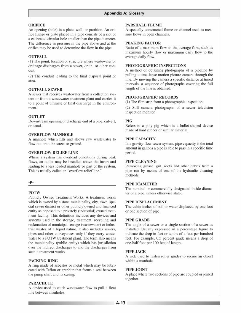
ORIFICEAn opening (hole) in a plate, wall, or partition. An ori-fice flange or plate placed in a pipe consists of a slot ora calibrated circular hole smaller than the pipe diameter.The difference in pressure in the pipe above and at theorifice may be used to determine the flow in the pipe.
OUTFALL(1) The point, location or structure where wastewater ordrainage discharges from a sewer, drain, or other con-duit.
(2) The conduit leading to the final disposal point orarea.
OUTFALL SEWERA sewer that receives wastewater from a collection sys-tem or from a wastewater treatment plant and carries itto a point of ultimate or final discharge in the environ-ment.
OUTLETDownstream opening or discharge end of a pipe, culvert,or canal.
OVERFLOW MANHOLEA manhole which fills and allows raw wastewater toflow out onto the street or ground.
OVERFLOW RELIEF LINEWhere a system has overload conditions during peakflows, an outlet may be installed above the invert andleading to a less loaded manhole or part of the system.This is usually called an “overflow relief line.”
-P-
POTWPublicly Owned Treatment Works. A treatment workswhich is owned by a state, municipality, city, town, spe-cial sewer district or other publicly owned and financedentity as opposed to a privately (industrial) owned treat-ment facility. This definition includes any devices andsystems used in the storage, treatment, recycling andreclamation of municipal sewage (wastewater) or indus-trial wastes of a liquid nature. It also includes sewers,pipes and other conveyances only if they carry waste-water to a POTW treatment plant. The term also meansthe municipality (public entity) which has jurisdictionover the indirect discharges to and the discharges fromsuch a treatment works.
PACKING RINGA ring made of asbestos or metal which may be lubri-cated with Teflon or graphite that forms a seal betweenthe pump shaft and its casing.
PARACHUTEA device used to catch wastewater flow to pull a floatline between manholes.
PARSHALL FLUMEA specially constructed flume or channel used to mea-sure flows in open channels.
PEAKING FACTORRatio of a maximum flow to the average flow, such asmaximum hourly flow or maximum daily flow to theaverage daily flow.
PHOTOGRAPHIC INSPECTIONSA method of obtaining photographs of a pipeline bypulling a time-lapse motion picture camera through theline. By moving the camera a specific distance at timedintervals, a sequence of photographs covering the fulllength of the line is obtained.
PHOTOGRAPHIC RECORDS(1) The film strip from a photographic inspection.
(2) Still camera photographs of a sewer televisioninspection monitor.
PIGRefers to a poly pig which is a bullet-shaped devicemade of hard rubber or similar material.
PIPE CAPACITYIn a gravity-flow sewer system, pipe capacity is the totalamount in gallons a pipe is able to pass in a specific timeperiod.
PIPE CLEANINGRemoving grease, grit, roots and other debris from apipe run by means of one of the hydraulic cleaningmethods.
PIPE DIAMETERThe nominal or commercially designated inside diame-ter of a pipe, unless otherwise stated.
PIPE DISPLACEMENTThe cubic inches of soil or water displaced by one footor one section of pipe.
PIPE GRADEThe angle of a sewer or a single section of a sewer asinstalled. Usually expressed in a percentage figure toindicate the drop in feet or tenths of a foot per hundredfeet. For example, 0.5 percent grade means a drop ofone-half foot per 100 feet of length.
PIPE JACKA jack used to fasten roller guides to secure an objectwithin a manhole.
PIPE JOINTA place where two sections of pipe are coupled or joinedtogether.
Appendix A: Glossary
A-13

Optimizing Operation, Maintenance, and Rehabilitation of Sanitary Sewer Collection Systems
A-14
PIPE JOINT SEAL(1) The tightness or lack of leakage at a pipe joint.
(2) The method of sealing a pipe coupling.
PIPE LINERA plastic liner pulled or pushed into a pipe to eliminateexcessive infiltration or exfiltration. Other solutions tothe problem of infiltration/exfiltration are the use ofcement grouting or replacement of damaged pipe.
PIPE PLUG(1) A temporary plug placed in a sewer pipe to stop aflow while repair work is being accomplished or otherfunctions are performed.
(2) In construction of a new sewer system, service sad-dles are sometimes installed before a building or a build-ing lateral is in existence. Under such circumstances, aplug will be placed in the off-lead of the saddle of a “Y.”
PIPE RODDINGA method of opening a plugged or blocked pipe bypushing a steel rod or snake, or pulling same, throughthe pipe with a tool attached to the end of the rod orsnake. Rotating the rod or snake with a tool attachedincreases effectiveness.
PIPE RUN(1) The length of sewer pipe reaching from one manholeto the next.
(2) Any length of pipe, generally assumed to be in astraight line.
PIPE SECTIONA single length of pipe between two joints or couplers.
PLANA drawing showing the TOP view of sewers, manholesand streets.
PNEUMATIC EJECTORA device for raising wastewater, sludge or other liquidby compressed air. The liquid is alternately admittedthrough an inward-swinging check valve into the bottomof an airtight pot. When the pot is filled compressed airis applied to the top of the liquid. The compressed airforces the inlet valve closed and forces the liquid in thepot through an outward-swinging check valve, thusemptying the pot.
POPULATION EQUIVALENT (HYDRAULIC)A flow of 100 gallons per day is the hydraulic or flowequivalent to the contribution or flow from one person.Population equivalent = 100 GPCD or gallons per capitaper day.
PORCUPINEA sewer cleaning tool the same diameter as the pipebeing cleaned. The tool is a steel cylinder having solid
ends with eyes cast in them to which a cable can beattached and pulled by a winch. Many short pieces ofcable or bristles protrude from the cylinder to form around brush.
POTABLE WATERWater that does not contain objectionable pollution, con-tamination, minerals, or infective agents and is consid-ered satisfactory for drinking.
POWER RODDERA sewer cleaning machine fitted with auger rods whichare inserted in a sewer line to dislodge and cut roots anddebris.
PRECIPITATION(1) The total measurable supply of water receiveddirectly from clouds as rain, snow, hail, or sleet; usuallyexpressed as depth in a day, month, or year, and desig-nated as daily, monthly, or annual precipitation.
(2) The process by which atmospheric moisture is dis-charged onto a land or water surfaces.
(3) The separation (of a substance) out in solid formfrom a solution, as by the use of a reagent.
PRE-CLEANINGSewer line cleaning, commonly done by high-velocitycleaners, that is done prior to the TV inspection of apipeline to remove grease, slime, and grit to allow for aclearer and more accurate identification of defects andproblems.
PRESSURE HEAD(1) The height of a water surface above a specific pointof reference. Usually measured in feet and tenths of afoot.
(2) The head represented by the expression of pressureover weight (p/w), where p is pressure (lbs/ sq ft) and wis weight (lbs/cu ft).
PREVENTIVE MAINTENANCECrews assigned the task of cleaning sewers (for exam-ple, balling or high-velocity cleaning crews) to preventstoppages and odor complaints. Preventive maintenanceis performing the most effective cleaning procedure, inthe area where it is most needed, at the proper time inorder to prevent failures and emergency situations.
PROFILEA drawing showing the SIDE view of sewers and man-holes.
PROTRUDING SERVICEThe connection of a building lateral to a main sewer linewhereby a hole is cut in the main and the end of thebuilding lateral is allowed to extend into the main.

PUMPA mechanical device for causing flow, for raising or lift-ing water or other fluid, or for applying pressure to flu-ids.
PUMP PITA dry well, chamber or room below ground level inwhich a pump is located.
PUMP STATIONInstallation of pumps to lift wastewater to a higher ele-vation in places where flat land would require exces-sively deep sewer trenches. Also used to raisewastewater from areas too low to drain into availablecollection lines. These stations may be equipped withair-operated ejectors or centrifugal pumps.
-Q-
QUICK AIR TESTThe same as a quick test with a packer for chemicalgrouting except that air pressure is used in place of liq-uid for a faster test and greater accuracy.
QUICK TESTUse of a packer designed for chemical grouting to pres-sure test any selected small area of pipeline.
-R-
RAINParticles of liquid water that have become too large to beheld by the atmosphere. Their diameter generally isgreater than 0.02 inch and they usually fall to the earthat velocities greater than 10 fps in still air.
REGULATORA device used in combined sewers to control or regulatethe diversion of flow.
RETENTION(1) That part of the precipitation falling on a drainagearea which does not escape as surface stream flow dur-ing a given period. It is the difference between total pre-cipitation and total runoff during the period, andrepresents evaporation, transpiration, subsurface leak-age, infiltration, and when short periods are considered,temporary surface or underground storage on the area.
(2) The delay or holding of the flow of water and water-carried wastes in a pipe system. This can be due to arestriction in the pipe, a stoppage or a dip. Also, the timewater is held or stored in a basin or wet well.
ROD GUIDEA bent pipe inserted in a manhole to guide hand andpower rods into collection lines so the rods can dislodgeobstructions.
ROD (SEWER)A light metal rod, three to five feet long with a couplingat each end. Rods are joined and pushed into a sewer todislodge obstructions.
RODDING MACHINEA machine designed to feed a rod into a pipe while rotat-ing the rod.
RODDING TOOLSSpecial tools attached to the end of a rod or snake toaccomplish various results in pipe rodding.
ROOF LEADERA downspout or pipe installed to drain a roof gutter to astorm drain or other means of disposal.
ROOT, SEWERAny part of a root system of a plant or tree that enters acollection system.
ROOT MOPWhen roots from plant life enter a sewer system, theroots frequently branch to form a growth that resemblesa string mop.
ROUGHNESS COEFFICIENTA value used in Manning’s formula to determine energylosses of flowing water due to pipe or channel wallroughness.
RUNOFFThat part of rain or other precipitation that runs off thesurface of a drainage area and does not enter the soil orthe sewer system.
-S-
SADDLEA fitting mounted on a pipe for attaching a new connec-tion. This device makes a tight seal against the main pipeby use of a clamp, adhesive, or gasket and prevents theservice pipe from protruding into the main.
SADDLE CONNECTIONA building service connection made to a sewer mainwith a device called a saddle.
SAND TRAPA device which can be placed in the outlet of a manholeto cause a settling pond to develop in the manhole invert,thus trapping sand, rocks and similar debris heavier thanwater. Also may be installed in outlets from car washareas.
SANITARY COLLECTION SYSTEMThe pipe system for collecting and carrying liquid andliquid-carried wastes from domestic sources to a waste-water treatment plant.
Appendix A: Glossary
A-15
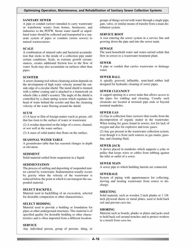
Optimizing Operation, Maintenance, and Rehabilitation of Sanitary Sewer Collection Systems
A-16
SANITARY SEWERA pipe or conduit (sewer) intended to carry wastewateror waterborne wastes from homes, businesses, andindustries to the POTW. Storm water runoff or unpol-luted water should be collected and transported in a sep-arate system of pipes or conduits (storm sewers) tonatural wastercourses.
SCALEA combination of mineral salts and bacterial accumula-tion that sticks to the inside of a collection pipe undercertain conditions. Scale, in extreme growth circum-stances, creates additional friction loss to the flow ofwater. Scale may also accumulate on surfaces other thanpipes.
SCOOTERA sewer cleaning tool whose cleansing action depends onthe development of high water velocity around the out-side edge of a circular shield. The metal shield is rimmedwith a rubber coating and is attached to a framework onwheels (like a child’s scooter). The angle of the shield iscontrolled by a chain-spring system which regulates thehead of water behind the scooter and thus the cleansingvelocity of the water flowing around the shield.
SCUM(1) A layer or film of foreign matter (such as grease, oil)that has risen to the surface of water or wastewater.
(2) A residue deposited on the ledge of a sewer, channel,or wet well at the water surface.
(3) A mass of solid matter that floats on the surface.
SEASONAL WATER TABLEA groundwater table that has seasonal changes in depthor elevation.
SEDIMENTSolid material settled from suspension in a liquid.
SEDIMENTATIONThe process of settling and depositing of suspended mat-ter carried by wastewater. Sedimentation usually occursby gravity when the velocity of the wastewater isreduced below the point at which it can transport the sus-pended material.
SELECT BACKFILLMaterial used in backfilling of an excavation, selectedfor desirable compaction or other characteristics.
SELECT BEDDINGMaterial used to provide a bedding or foundation forpipes or other underground structures. This material is ofspecified quality for desirable bedding or other charac-teristics and is often imported from a different location.
SERVICEAny individual person, group of persons, thing, or
groups of things served with water through a single pipe,gate, valve, or similar means of transfer from a main dis-tribution system.
SERVICE ROOTA root entering the sewer system in a service line andgrowing down the pipe and into the sewer main.
SEWAGEThe used household water and water-carried solids thatflow in sewers to a wastewater treatment plant.
SEWERA pipe or conduit that carries wastewater or drainagewater.
SEWER BALLA spirally grooved, inflatable, semi-hard rubber balldesigned for hydraulic cleaning of sewer pipes.
SEWER CLEANOUTA capped opening in a sewer main that allows access tothe pipes for rodding and cleaning. Usually suchcleanouts are located at terminal pipe ends or beyondterminal manholes.
SEWER GAS(1) Gas in collection lines (sewers) that results from thedecomposition of organic matter in the wastewater.When testing for gases found in sewers, test for lack ofoxygen and also for explosive and toxic gases.
(2) Any gas present in the wastewater collection system,even though it is from such sources as gas mains, gaso-line, and cleaning fluid.
SEWER JACKA device placed in manholes which supports a yoke orpulley that keeps wires or cables from rubbing againstthe inlet or outlet of a sewer.
SEWER MAINA sewer pipe to which building laterals are connected.
SEWERAGESystem of piping with appurtenances for collecting,moving and treating wastewater from source to dis-charge.
SHEETINGSolid material, such as wooden 2-inch planks or 1 1/8-inch plywood sheets or metal plates, used to hold backsoil and prevent cave-ins.
SHORINGMaterial such as boards, planks or plates and jacks usedto hold back soil around trenches and to protect workersin a trench from cave-ins.
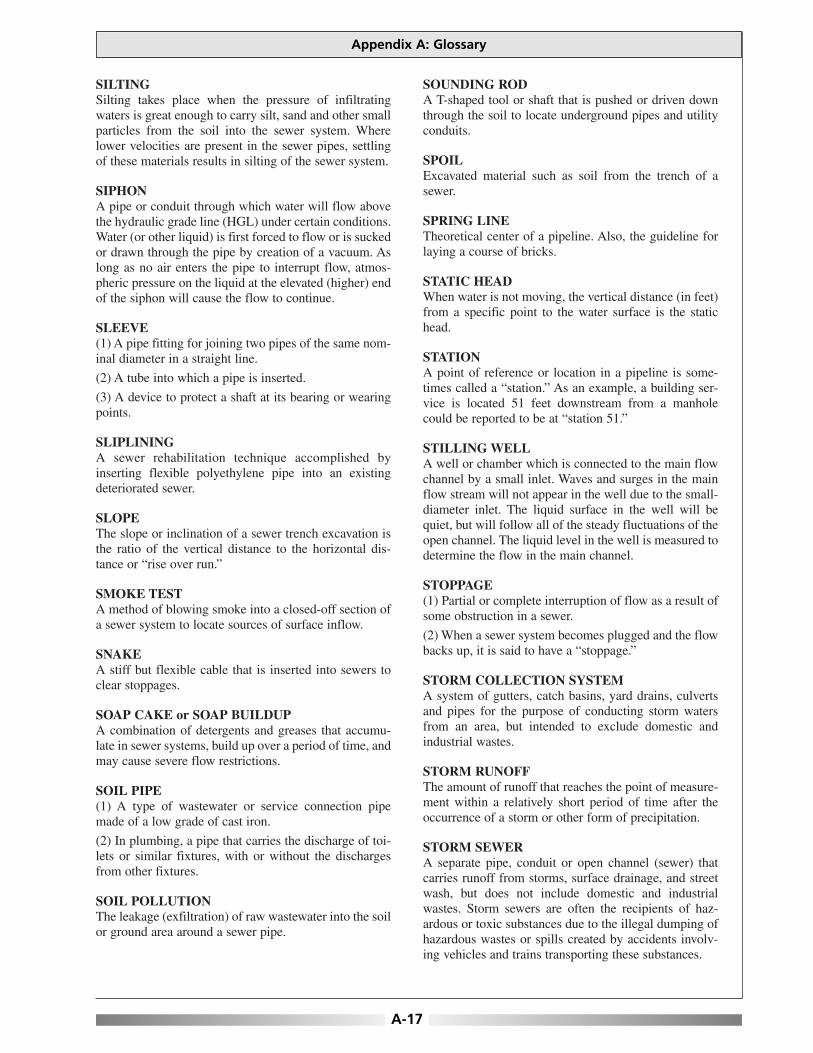
SILTINGSilting takes place when the pressure of infiltratingwaters is great enough to carry silt, sand and other smallparticles from the soil into the sewer system. Wherelower velocities are present in the sewer pipes, settlingof these materials results in silting of the sewer system.
SIPHONA pipe or conduit through which water will flow abovethe hydraulic grade line (HGL) under certain conditions.Water (or other liquid) is first forced to flow or is suckedor drawn through the pipe by creation of a vacuum. Aslong as no air enters the pipe to interrupt flow, atmos-pheric pressure on the liquid at the elevated (higher) endof the siphon will cause the flow to continue.
SLEEVE(1) A pipe fitting for joining two pipes of the same nom-inal diameter in a straight line.
(2) A tube into which a pipe is inserted.
(3) A device to protect a shaft at its bearing or wearingpoints.
SLIPLININGA sewer rehabilitation technique accomplished byinserting flexible polyethylene pipe into an existingdeteriorated sewer.
SLOPEThe slope or inclination of a sewer trench excavation isthe ratio of the vertical distance to the horizontal dis-tance or “rise over run.”
SMOKE TESTA method of blowing smoke into a closed-off section ofa sewer system to locate sources of surface inflow.
SNAKEA stiff but flexible cable that is inserted into sewers toclear stoppages.
SOAP CAKE or SOAP BUILDUPA combination of detergents and greases that accumu-late in sewer systems, build up over a period of time, andmay cause severe flow restrictions.
SOIL PIPE(1) A type of wastewater or service connection pipemade of a low grade of cast iron.
(2) In plumbing, a pipe that carries the discharge of toi-lets or similar fixtures, with or without the dischargesfrom other fixtures.
SOIL POLLUTIONThe leakage (exfiltration) of raw wastewater into the soilor ground area around a sewer pipe.
SOUNDING RODA T-shaped tool or shaft that is pushed or driven downthrough the soil to locate underground pipes and utilityconduits.
SPOILExcavated material such as soil from the trench of asewer.
SPRING LINETheoretical center of a pipeline. Also, the guideline forlaying a course of bricks.
STATIC HEADWhen water is not moving, the vertical distance (in feet)from a specific point to the water surface is the statichead.
STATIONA point of reference or location in a pipeline is some-times called a “station.” As an example, a building ser-vice is located 51 feet downstream from a manholecould be reported to be at “station 51.”
STILLING WELLA well or chamber which is connected to the main flowchannel by a small inlet. Waves and surges in the mainflow stream will not appear in the well due to the small-diameter inlet. The liquid surface in the well will bequiet, but will follow all of the steady fluctuations of theopen channel. The liquid level in the well is measured todetermine the flow in the main channel.
STOPPAGE(1) Partial or complete interruption of flow as a result ofsome obstruction in a sewer.
(2) When a sewer system becomes plugged and the flowbacks up, it is said to have a “stoppage.”
STORM COLLECTION SYSTEMA system of gutters, catch basins, yard drains, culvertsand pipes for the purpose of conducting storm watersfrom an area, but intended to exclude domestic andindustrial wastes.
STORM RUNOFFThe amount of runoff that reaches the point of measure-ment within a relatively short period of time after theoccurrence of a storm or other form of precipitation.
STORM SEWERA separate pipe, conduit or open channel (sewer) thatcarries runoff from storms, surface drainage, and streetwash, but does not include domestic and industrialwastes. Storm sewers are often the recipients of haz-ardous or toxic substances due to the illegal dumping ofhazardous wastes or spills created by accidents involv-ing vehicles and trains transporting these substances.
Appendix A: Glossary
A-17

Optimizing Operation, Maintenance, and Rehabilitation of Sanitary Sewer Collection Systems
A-18
STORM WATERThe excess water running off from the surface of adrainage area during and immediately after a period ofrain.
STORM WATER INLETA device that admits surface waters to the storm waterdrainage system.
STRETCHLength of sewer from manhole to manhole.
STRUCTURAL DEFECTA flaw or imperfection of a structure or design whichwas built into a project, pipeline or other collection sys-tem appurtenance.
STRUCTURAL FAILUREA condition that exists when one or more components ofa system break down or fail to perform as expected. Astructural failure may result from defective parts ordesign or may result from other circumstances that occurafter the completion of construction.
SUBSIDENCEThe dropping or lowering of the ground surface as aresult of removing excess water (overdraft or overpump-ing) from an aquifer. After excess water has beenremoved, the soil will settle, become compacted and theground surface will drop and can cause the settling ofunderground utilities.
SUBSYSTEMAn extensive underground sewer system connected tothe main collection system, but not considered part ofthe main system. An example might be the undergroundsewer system of a mobile home park.
SUCKER RODSRigid, coupled sewer rods of metal or wood used forclearing stoppages. Usually available in 3-ft, 39-in, 4-ft,5-ft and 6-ft lengths.
SUCTION HEADThe POSITIVE pressure (in feet or pounds per squareinch (psi)) on the suction side of a pump. The pressurecan be measured from the centerline of the pump UP TOthe elevation of the hydraulic grade line on the suctionside of the pump.
SUCTION LIFTThe NEGATIVE pressure (in feet or inches of mercuryvacuum) on the suction side of the pump. The pressurecan be measured from the centerline of the pumpDOWN TO (lift) the elevation of the hydraulic gradeline on the suction side of the pump.
SURCHARGESewers are surcharged when the supply of water to becarried is greater than the capacity of the pipes to carry
the flow. The surface of the wastewater in manholesrises above the top of the sewer pipe, and the sewer isunder pressure or a head, rather than at atmosphericpressure.
SURCHARGED MANHOLEA manhole in which the rate of the water entering isgreater than the capacity of the outlet under gravity flowconditions. When the water in the manhole rises abovethe top of the outlet pipe, the manhole is said to be “sur-charged.”
SURFACE RUNOFF(1) The precipitation that cannot be absorbed by the soiland flows across the surface by gravity.
(2) The water that reaches a stream by traveling over thesoil surface or falls directly into the stream channels,including not only the large permanent streams but alsothe tiny rills and rivulets.
(3) Water that remains after infiltration, interception, andsurface storage have been deducted from total precipita-tion.
SURFACED DEFECTA break or opening in a sewer pipe where the coveringsoil has been washed away and the opening or break isexposed on the ground surface.
SURFACED VOIDA dip or depression in the ground that appears when silt-ing has taken place to a degree that a void is caused inthe subsoil. Through successive cave-ins, the voidreaches the surface of the ground.
SURVEILLANCE TELEVISION EQUIPMENTEconomically closed-circuit television equipmentdesigned for surveillance or security work in commer-cial facilities. Picture resolutions generally range from250 to 350 lines.
SUSPENDED SOLIDS(1) Solids that either float on the surface or are sus-pended in water, wastewater, or other liquids, and whichare largely removable by laboratory filtering.
(2) The quantity of material removed from wastewater ina laboratory test, as prescribed in STANDARD METH-ODS FOR THE EXAMINATION OF WATER ANDWASTEWATER, and referred to as Total SuspendedSolids Dried at 103-105 ºC.
SWABA circular sewer cleaning tool almost the same diameteras the pipe being cleaned. As a final cleaning procedureafter a sewer line has been cleaned with a porcupine, aswab is pulled through the sewer and the flushing actionof water flowing around the tool cleans the line.

-T-
TAG LINEA line, rope or cable that follows equipment through asewer so that equipment can be pulled back out if itencounters an obstruction or becomes stuck. Equipmentis pulled forward with a pull line.
TAPA small hole in a sewer where a wastewater service linefrom a building is connected (tapped) into a lateral orbranch sewer.
TELEMETERING EQUIPMENTEquipment that translates physical measurements intoelectrical impulses that are transmitted to dials orrecorders.
TELEMETRYThe electrical link between the transmitter and thereceiver. Telephone lines are commonly used to serve asthe electrical line.
TELEVISION INSPECTIONAn inspection of the inside of a sewer pipe made bypulling a closed-circuit television camera through thepipe.
TELEVISION INSPECTION LOGA record of a pipeline television inspection which pro-vides date, line location, footage distances, pipe quadrantlocations and descriptions of all conditions observed inthe inspection. When this log is written, it is called a“written recording.” When it is voice recorded on a tape,it is called a “voice tape recording.” If the picture isrecorded with a videotape recorder with audio remarks, itis called a “video-voice inspection record.” Where data-view reporting is used, it is called a VIDEO LOG.
TELEVISION MONITORThe television set or kinescope where the picture isviewed on a closed-circuit system.
TERMINAL CLEANOUTWhen a manhole is not provided at the upstream end ofa sewer main, a cleanout is usually provided. This iscalled a “terminal cleanout.”
TERMINAL MANHOLEA manhole located at the upstream end of a sewer andhaving no inlet pipe.
THRUST BLOCKA mass of concrete or similar material appropriatelyplaced around a pipe to prevent movement when thepipe is carrying water. Usually placed at bends and valvestructures.
TOTAL CONTRIBUTIONAll water and wastewater entering a sewer system from
a specific facility, subsystem or area. This includesdomestic and industrial wastewaters, inflow and infiltra-tion reaching the main collection system.
TOTAL DYNAMIC HEAD (TDH)When a pump is lifting or pumping water, the verticaldistance (in feet) from the elevation of the energy gradeline on the suction side of the pump to the elevation ofthe energy grade line on the discharge side of the pump.
TOTAL FLOWThe total flow passing a selected point of measurementin the collection system during a specified period oftime.
TRAP(1) In the wastewater collection system of a building,plumbing codes require every drain connection from anappliance or fixture to have a trap. The trap in this caseis a gooseneck that holds water to prevent vapors orgases in a collection system from entering the building.
(2) Various other types of special traps are used in col-lection systems such as a grit trap or sand trap.
TRENCH JACKMechanical screw device used to hold shoring in place.
TRUNK SEWERA sewer that receives wastewater from many tributarybranches or sewers and serves a large territory and con-tributing population.
TRUNK SYSTEMA system of major sewers serving as transporting linesand not as local or lateral sewers.
TURBIDHaving a cloudy or muddy appearance.
TV LOGA written record of the internal pipe conditions observedduring a sewer line TV inspection.
TWO-WAY CLEANOUTAn opening in pipes or sewers designed for rodding orworking a snake into the pipe in either direction. Two-way cleanouts are most often found in building lateralpipes at or near a property line.
-V-
V-NOTCH WEIRA triangular weir with a “V” notch calibrated in gallonsper minute readings. By holding the weir in a pipe withrubber seals forcing a flow to pass through the “V,” ameasure of the gallonage flowing through the pipe canbe read on the basis of the depth of water flowing overthe weir.
Appendix A: Glossary
A-19

Optimizing Operation, Maintenance, and Rehabilitation of Sanitary Sewer Collection Systems
A-20
VAC-ALLEquipment that removes solids from a manhole as theyenter the manhole from a hydraulic cleaning operation.Most of the wastewater removed from the manhole bythe operation is separated from the solids and returned tothe sewer.
VELOCITY HEADThe energy in flowing water as determined by a verticalheight (in feet or meters) equal to the square of thevelocity of flowing water divided by twice the accelera-tion due to gravity (V2/2g).
VERTICAL OFFSETA pipe joint in which one section is connected to anotherat a different elevation.
VIDEO INSPECTIONA television inspection.
VIDEO LOGA magnetic tape picture recording of a television inspec-tion where data-view reporting has been included as partof the visual record.
VIDEOTAPEA magnetic tape for recording television pictures.Standard tapes also have a capacity to record a voicewith the picture, or an “audio” accompaniment.
VOIDA pore or open space in rock, soil or other granularmaterial, not occupied by solid matter. The pore or openspace may be occupied by air, water, or other gaseous orliquid material.
-W-
WASTELINE CLEANOUTAn opening or point of access in a building wastewaterpipe system for rodding or snake operation.
WASTELINE VENTMost plumbing codes require a vent pipe connection ofadequate size and located downstream of a trap in abuilding wastewater system. This vent prevents theaccumulation of gases or odors and is usually pipedthrough the roof and out of doors.
WASTEWATERA community’s used water and water-carried solids thatflow to a treatment plant. Storm water, surface water,and groundwater infiltration also may be included in thewastewater that enters a wastewater treatment plant. Theterm “sewage” usually refers to household wastes, butthis word is being replaced by the term “wastewater.”
WASTEWATER COLLECTION SYSTEMThe pipe system for collecting and carrying water andwater-carried wastes from domestic and industrialsources to a wastewater treatment plant.
WASTEWATER FACILITIESThe pipes, conduits, structures, equipment, andprocesses required to collect, convey, and treat domesticand industrial wastes, and dispose of the effluent andsludge.
WASTEWATER TREATMENT PLANT(1) An arrangement of pipes, equipment, devices, tanksand structures for treating wastewater and industrialwastes.
(2) A water pollution control plant.
WAYNE BALLA spirally grooved, inflatable, semi-hard rubber balldesigned for hydraulic cleaning of sewer pipes.
WEIR(1) A wall or plate placed in an open channel and usedto measure the flow of water. The depth of the flow overthe weir can be used to calculate the flow rate, or a chartor conversion table may be used to convert depth to flow.
(2) A wall or obstruction used to control flow (from set-tling tanks and clarifiers) to ensure a uniform flow rateand avoid short-circulating.
WET WELLA compartment or tank in which wastewater is collected.The suction pipe of a pump may be connected to the wetwell or a submersible pump may be located in the wetwell.
WETTED PERIMETERThe length of the wetted portion of a pipe covered byflowing wastewater.

This appendix contains generic standard operation procedures (SOPs) for routine day-to-daycollection system operation and maintenance activities. These generic SOPs can be adapted to fitspecific collection system needs. They are not presented as inclusive of all situations orcircumstances.
Optimizing Operation, Maintenance, and Rehabilitation of Sanitary Sewer Collection Systems
B-1
APPENDIX BDAY-TO-DAY STANDARD OPERATING PROCEDURES
Install, Relay, Repair, or Abandonment of Wastewater Gravity Main B-3
Install, Relay, or Repair of House Connection B-9
Install Wastewater Clean-Out B-15
Install Wastewater Manhole B-19
Repair of Wastewater Manhole B-23
Rehabilitation, Relay, Repair, or Abandonment of Wastewater Force Main B-29
Unblock or Clear Wastewater Stop-Up or Back-Up and Contain Manhole Overflow B-35
Vactor Truck Operation B-39
Smoke Testing B-43

This page is intentionally blank.

INSTALL, RELAY, REPAIR, OR ABANDONMENT OF WASTEWATER GRAVITY MAIN
Objective: This Maintenance activity is performed to install, relay, repair or abandon wastewatergravity mains whose integrity has been compromised due to cracks, breaks, collapses due to soilmovement, impact, root intrusion contact with other structures, temperatures, corrosion due tohydrogen sulfide, improper laying or repair, and combinations of any of the above.
It should be noted that contact with raw sewage is a potential health hazard and care should be takento prevent contamination of uniform, skin, or tools by using appropriate personal protective equipmentas may be necessary due to field conditions at the job site. IT IS ESSENTIAL THAT GOODHYGIENE PRACTICES BE USED DURING OPERATIONS AND APPROPRIATE CLEAN-UPAFTER WORK IS COMPLETED TO ENSURE SAFETY.
Personal Safety Equipment:Hard Hat, Back Brace (For Heavy Lifting), Safety Glasses, Full Face Shield,Safety Vests, Work Gloves, Elbow Length Rubber Gloves, Steel Toed Workand/or Rubber Boots, (APR) Respirator, Environmental Coveralls, IsopropylAlcohol, and Ear Protection.
Job Site Safety Equipment:Ladder (Extra Heavy Duty Industrial with IA Duty Rating), Safety Harness,Safety Rope, Gas Detector, Traffic Wand, Traffic Control Devices such asFlags, Flag Stands, Cones Barricades, and Arrowboard, Mesh Safety Fencing,Shoring and/or Trench Box
Construction Equipment:Backhoe, Jackhammer, Shovels, Hydrant Wrench, Water Pump, Suction andDischarge Hoses, Quickie Saw, Wrenches, Tamper, Air Compressor, Laser,Surveyor's Level, String Line, Batter Board, Transit, Philadelphia Rod (GradeRod), Pipe Burster, Pipe Beveler, Rasp, Small Hand Tools, Chain, Sling, Jute,Air Plugs or Wing Plugs, Steel Plates, Generator with GFCI, Flood Lights,Hand Lights, Drop Lights with Heavy Duty Bulb U.A. Rated Explosion Proof,and Lift Truck.
Erosion Controls:Sand Bag, Filter Dike and/or Silt Fence.
Construction Materials:Approved Pipe (appropriate to type of pipe in ground), Rubber Adapters andStainless Steel Clamps (appropriate to type of material in ground), Retainersand Sleeves, Brick or Concrete Support Blocks, Cement as Required, SelectBackfill Materials (flexible base, gem sand, crushed rock, washed rock or twosack flowable fill), 9 mil Polywrap, Poly Tape, Clean Rags, and Cold Mix.
Reference Materials:Quads, As-Builts, Profiles, and Aperture Cards.
Appendix B: Day-to-Day Standard Operating Procedures
B-3
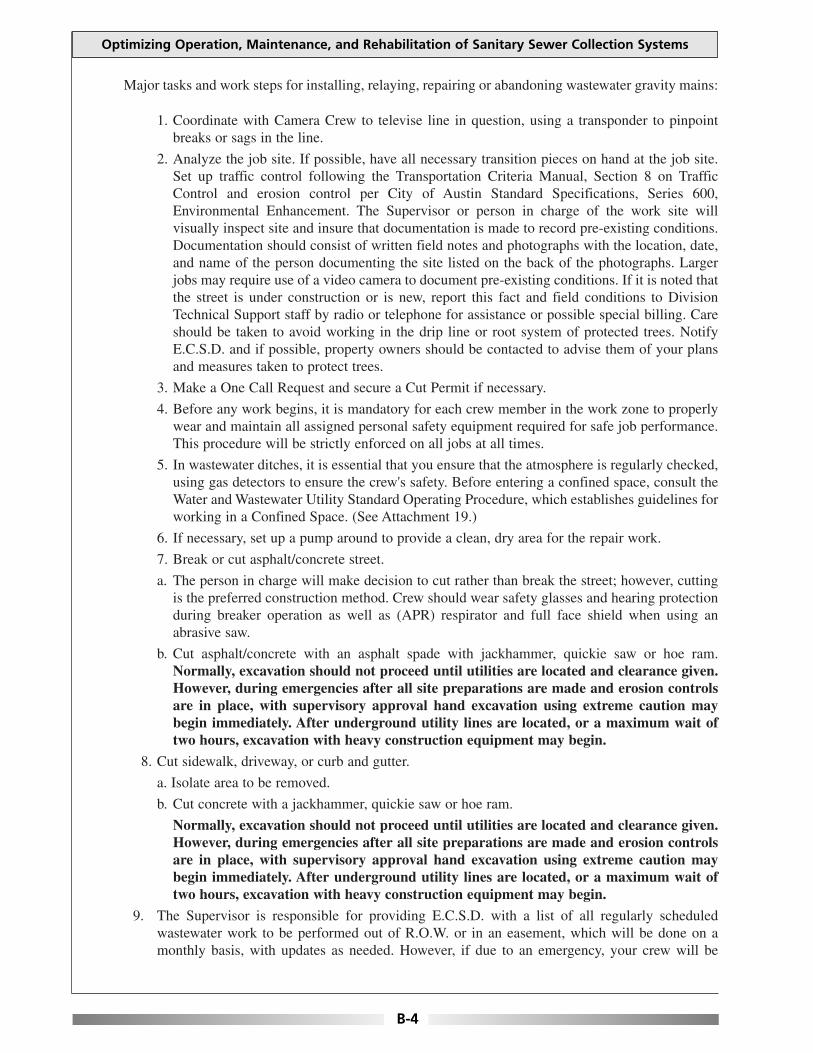
Major tasks and work steps for installing, relaying, repairing or abandoning wastewater gravity mains:
1. Coordinate with Camera Crew to televise line in question, using a transponder to pinpointbreaks or sags in the line.
2. Analyze the job site. If possible, have all necessary transition pieces on hand at the job site.Set up traffic control following the Transportation Criteria Manual, Section 8 on TrafficControl and erosion control per City of Austin Standard Specifications, Series 600,Environmental Enhancement. The Supervisor or person in charge of the work site willvisually inspect site and insure that documentation is made to record pre-existing conditions.Documentation should consist of written field notes and photographs with the location, date,and name of the person documenting the site listed on the back of the photographs. Largerjobs may require use of a video camera to document pre-existing conditions. If it is noted thatthe street is under construction or is new, report this fact and field conditions to DivisionTechnical Support staff by radio or telephone for assistance or possible special billing. Careshould be taken to avoid working in the drip line or root system of protected trees. NotifyE.C.S.D. and if possible, property owners should be contacted to advise them of your plansand measures taken to protect trees.
3. Make a One Call Request and secure a Cut Permit if necessary.
4. Before any work begins, it is mandatory for each crew member in the work zone to properlywear and maintain all assigned personal safety equipment required for safe job performance.This procedure will be strictly enforced on all jobs at all times.
5. In wastewater ditches, it is essential that you ensure that the atmosphere is regularly checked,using gas detectors to ensure the crew's safety. Before entering a confined space, consult theWater and Wastewater Utility Standard Operating Procedure, which establishes guidelines forworking in a Confined Space. (See Attachment 19.)
6. If necessary, set up a pump around to provide a clean, dry area for the repair work.
7. Break or cut asphalt/concrete street.
a. The person in charge will make decision to cut rather than break the street; however, cuttingis the preferred construction method. Crew should wear safety glasses and hearing protectionduring breaker operation as well as (APR) respirator and full face shield when using anabrasive saw.
b. Cut asphalt/concrete with an asphalt spade with jackhammer, quickie saw or hoe ram.Normally, excavation should not proceed until utilities are located and clearance given.However, during emergencies after all site preparations are made and erosion controlsare in place, with supervisory approval hand excavation using extreme caution maybegin immediately. After underground utility lines are located, or a maximum wait oftwo hours, excavation with heavy construction equipment may begin.
8. Cut sidewalk, driveway, or curb and gutter.
a. Isolate area to be removed.
b. Cut concrete with a jackhammer, quickie saw or hoe ram.
Normally, excavation should not proceed until utilities are located and clearance given.However, during emergencies after all site preparations are made and erosion controlsare in place, with supervisory approval hand excavation using extreme caution maybegin immediately. After underground utility lines are located, or a maximum wait oftwo hours, excavation with heavy construction equipment may begin.
9. The Supervisor is responsible for providing E.C.S.D. with a list of all regularly scheduledwastewater work to be performed out of R.O.W. or in an easement, which will be done on amonthly basis, with updates as needed. However, if due to an emergency, your crew will be
Optimizing Operation, Maintenance, and Rehabilitation of Sanitary Sewer Collection Systems
B-4

working in an easement or creekbed; E.C.S.D. should be notified before beginning work. Insurethat appropriate erosion controls and possible spill confinement measures are taken.
10. Dig hole to expose main. Care should be taken to prevent additional damage to areas outside thetrenchline.
a. If there is low risk of damaging underground utilities, preferred method is to use backhoe;and/or by hand with shovel, if not.
b. Dig down to flowline. If bedding is contaminated or too wet, then dig down at least 18 inchesbelow damaged or broken pipe or until stable material is found, and remove all unsuitablematerials.
11. On trenches 5 feet deep or greater, OSHA regulations require a trench safety system. Follow themanufacturer's Tabulated Data Sheet for shoring chosen as the trench safety system appropriateto the type of soil conditions prevalent on the job undertaken. This data sheet should be keptwith the trench shoring equipment at all times. As an alternate method, sloping may be usedfollowing OSHA guidelines. Trench shoring or sloping should be used if there is any questionabout the safety of the trench, regardless of trench depth. A ladder is required in any trench 4feet deep or greater, with additional ladders placed every 25 feet. The ladder should be aminimum height of 3 feet higher than the existing embankment. Insure that lighting is adequateto safely perform the necessary work.
12. If ground water is encountered, set up pump and dewater trench as necessary.
13. Establish a method of maintaining proper grade by any of the following method:
a. Batterboard and Stringline: Set up a batterboard (a 2 inch by 4 inch straight edge that willextend across the ditch). Set a string at the same elevation above the flowline at both points.Pull the string as tightly as possible. Check the string with a 2 foot level from the bottom ofthe string to insure that flow is in right direction. Then take a grade pole with a shelving "L"and mark pole at a predetermined point from the flowline. Then mark the grade pole for thethickness of the pipe, and finally mark the grade pole 6 inches above the bottom of the pipemark (for bedding depth).
b. Laser: The laser is set up in essentially the same manner as the batterboard and stringline. Itshoots grade from flowline to flowline after you dial in the percent.
c. Philadelphia Rod (Grade Rod), Surveyor's Level or Transit: Take the difference in elevationof the flowline, between starting and ending points, and divide this by the distance to get thefeet of rise per foot--always working from the low point.
14. Before any extensive repairs are made to a wastewater line, consult the list of rehab jobs or withDivision Technical Support Staff before making decision about what and how repairs shouldproceed. Possible types of repairs that may be made are as follows:
a. For pipe that has deteriorated or is in poor condition, remove the existing pipe, startingdownstream and staying on the downhill side. Work uphill to the high point. Work from thefirst good bell on the low side to the first good spigot on the high side. If there are very poorpipe conditions, lay new section(s) from manhole to manhole, starting at the lowest manholeand working to the highest manhole with bell ends pointing uphill.
b. Other types of repairs that can be made to pipe which has not deteriorated badly are: sliplining existing pipe, Insituform repairs, pipe bursting, micro tunneling, or actualreconstruction of the wastewater main.
15. If existing material in place is found to be different than planned upon, insure you getappropriate couplings for the material in place.
16. Remove all unstable material and the old pipe.
Appendix B: Day-to-Day Standard Operating Procedures
B-5

17. Rebed the ditch to proper grade using one of the methods in number 13 above listed.
18. Make sure the flowlines match when installing the first joint of pipe. If using a rubber coupling,ensure it is supported with a concrete cradle. The cradle should extend 3 inches beyond the widthof the coupling. Insure there is no loose material under the concrete cradle as this should sit ona stabilized portion of the ditch (this may or may not sit on bedding material).
19. When existing services are encountered, if possible install a new main size by 6 inch gasketed"Tee". If it is not possible to install a "Tee", then a main size by 6 inch saddle with stainless steelstraps may be used in emergency situations only.
CAUTION: Insure that hole in the pipe has been cut to proper dimensions prior toinstalling tap saddle. The hole should be centered in the direction and grade of the existingservice.
Check to insure that the main pipe is properly aligned and does not have any obstructions orjagged edges, using a rasp or grinding tool to remove obstructions or jagged edges. Make surethat the locator ring or shoulder is properly fitted inside the cut opening. Insure that all clampshave been properly installed and tightened. After the "Tee" or tap saddle has been properlyinstalled, reconnect the service to the main, insuring that the gasket has been properly installed.
20 Finish laying all pipe. During pipe installation insure that no joints are glued and that all gasketsare properly placed in the bell end, except when dealing with a pressurized system or when PVCSchedule 40 pipe is used. Bed and blind pipe. If possible before backfilling pipe, retelevise lineto insure all sags have been eliminated and that offset is correct. If scheduling of Camera Crewwill not allow pipe to be retelevised before backfilling is complete, schedule this activity as soonas possible.
21. During activities to install, relay or repair wastewater gravity flow mains, if it is determined thatthe line needs to be abandoned; the following should be done:
a. Set up a smoke test for the section to be abandoned to verify that no live or improperlyabandoned service connections exist.
b. Abandon wastewater gravity flow main by plugging upstream end of the main at the manholeinvert(s) or at the end of the main, using concrete, mortar and bricks.
c. Plug the downstream end of the main at the manhole invert(s) or at the end of the main, usingconcrete, mortar and bricks.
22. If it is determined that it is necessary to abandon a manhole, the following should be done:
a. Remove the ring and cover. The manhole needs to be lowered to a minimum of 36 inchesbelow existing street or ground surface.
b. Plug the invert on both sides with brick and mortar, placing brick 12 inches into the pipe.
c. If the manhole to be abandoned is located in the street or is susceptible to being "washed out",fill it with flowable fill.
d. If the manhole to be abandoned is located in any other area than those listed in "c" above, fillit with sand or gravel and cap it with 12 inches of concrete.
23. Backfill pipe according to City of Austin Standard Specifications, Series 500, Pipe andAppurtenances, Section 510, Pipe. This should be done carefully to prevent damage to the newlyplaced pipe.
a. Backfill pipe with gem sand, sand or washed rock in uniform lifts a minimum of 6 inchesunder the pipe to 12 inches or a maximum of 18 inches over the top of the pipe, dependingon the depth of the pipe. On temporary repairs, do not use sand bedding material.
b. Lay polywrap or filter fabric over gravel or washed rock to prevent migration of backfill andpossible trench failure.
Optimizing Operation, Maintenance, and Rehabilitation of Sanitary Sewer Collection Systems
B-6
24. Backfill any trench/subgrade located in right of way with select material, using the UtilityCriteria Manual, Section 5, "Cuts in Public Rights of Way" in uniform layers not exceeding 6inches in depth and tamping each layer in accordance with specifications (95% compaction isrequired).
a. Flexible base placed should be equal to existing material in place or a minimum of 10 inches,whichever is greater. It should be compacted in 6 inch lifts in accordance with specifications(100% compaction is required) and should be placed to within 2 inches of the existing surface.
b. Apply temporary paving (cold mix) and compact to existing grade.
c. If street is less than two years old, follow Section 5.5.4.E. of the Utility Criteria Manual forCuts in New Streets.
25. Remove spoil, insuring that all contaminated spoils are handled in an appropriate manner andhauled to an approved site for proper disposal. Clean up work site and remove erosion controlsif possible. Always insure that work site is properly cleaned before removing any erosioncontrols. If backfill is behind the curb or in an easement, all areas to receive vegetation shouldbe compacted in 6 inch lifts to 95% compaction, to within 4 inches from finished grade. This canbe accomplished by using a jumping jack, air tamper, or other approved equipment. Dress thearea for vegetation and restore to original condition per stipulations of the General Permit.Maintain erosion controls in place until such time as vegetation has adequately covered disturbedarea. Then remove them per City of Austin Standard Specifications, Series 600 EnvironmentalEnhancement.
26. Remove traffic control devices following the Transportation Criteria Manual, Section 8 onTraffic Control.
27. Before leaving the site ensure proper clean-up and disinfection of all contaminated uniforms andtools to ensure health and safety of personnel. Place doorhanger with information regardingwork done, supervisor's name, and telephone number for any questions customer may have. Ifwork is done after hours, write your name and telephone number in the appropriate space on thedoorhanger as the person responsible for the work done. Also place the name and telephonenumber of the day zone supervisor so the customer can contact them if they have urgent needsor questions regarding the work done. Never place notice in customer's mailbox and usecaution when entering private property at night.
28. If there are any changes in the location of this line or the type of material used, send marked upas-builts or profile to Division Technical Support staff so it can be sent to Maps and Records,TAPS and Dispatch for updating system maps and records.
29. Fill out a Job Completion Report, Status Report, and if needed a Property Damage Report and/orSpecial Billing Report and other related, required documentation completely and in a timelymanner. If a customer, plumber or third party is being special billed for this work, it is importantthat the proper notification is made to Dispatch so that Law Department is notified. Insure thatreports for these charges reflect all actual time, equipment and materials so charges are accurate.
30. If permanent repairs were made by Public Works, upon receipt of the Fixed Priced PaymentOrder the Supervisor will insure that the work site is checked before payment approval is made.If there are any problems with the work done or with the way the site was left, Public Worksshould be notified in writing so that any unacceptable work can be rectified before payment forthe job is approved.
31. When installing, relaying, or repairing a wastewater main, there are certain incidental activitiespertaining to wastewater construction or repair that may be regulated by Texas Natural ResourceConservation Commission or other entities. These activities have been subdivided and succinctlydescribed so that you are familiar with the most common of these. For any specific problems youmay encounter with any of the following, get with Division Technical Support staff forassistance.
Appendix B: Day-to-Day Standard Operating Procedures
B-7
1. PARALLEL LAY OR CROSSING OF WATER LINES
When installing a wastewater line parallel to, or crossing a water line, you must insure that at aminimum, 150 psi pressure rated pipe is used. The pipe must be centered to allow a separation of 9feet on either side of the existing water line. Additionally, pressure rated fittings must be used on bothends of the pressure rated pipe. These fittings may consist of a coated, solid sleeve with a transitiongasket or other approved products from the Utility's Standard Products List for wastewater.
For wastewater mains that cannot be installed with a separation of a minimum of 9 feet from theexisting water line, pressure rated pipe and fittings must be used.
Preferred construction method is to maintain a separation of a minimum of 4 feet from the existingwater line for all new wastewater installation. Exceptions from this norm should be discussed withDivision Technical Support staff or Utility Engineering staff.
2. CREEK CROSSING
When installing a wastewater line, if it is necessary to cross a creekbed; the preferred constructionmethod is to use lined Ductile Iron pipe. If this is not available, use SDR-35. In any event, either typeof pipe used should be encased in concrete.
Depending on field conditions, special backfill and trench/cap encasement may be required. Consultwith Division Technical Support staff for assistance.
3. AERIAL OR BRIDGE CROSSING
When installing a wastewater line that will be suspended aerially, the preferred construction methodis to use Yellowmine (U.V. resistant) Pipe or Ductile Iron Pipe (with restrained joints). An appropriatesupport structure equal to or better than existing should be designed for this work, depending onexisting site conditions. For assistance with design or installation of these lines, consult with DivisionTechnical Support staff.
Optimizing Operation, Maintenance, and Rehabilitation of Sanitary Sewer Collection Systems
B-8
INSTALL, RELAY, OR REPAIR OF HOUSE CONNECTION
Objective: This Maintenance activity is performed to install, relay or repair a wastewater houseconnection whose integrity has been compromised due to cracks, breaks, collapses due to soilmovement, impact, root intrusion, contact with other structures, temperatures, corrosion due tohydrogen sulfide, improper laying or repair, and combinations of any of the above. This task may beperformed because of problems with an existing house connection or because it was inadvertentlyforgotten during construction.
It should be noted that contact with raw sewage is a potential health hazard and care should be takento prevent contamination of uniform, skin, or tools by using appropriate personal protective equipmentas may be necessary due to field conditions at the job site. IT IS ESSENTIAL THAT GOODHYGIENE PRACTICES BE USED DURING OPERATIONS AND APPROPRIATE CLEAN-UP AFTER WORK IS COMPLETED TO ENSURE SAFETY.
Personal Safety Equipment:Hard Hat, Back Brace (For Heavy Lifting), Safety Glasses, Full Face Shield,Safety Vests, Work Gloves, Elbow Length Rubber Gloves, Steel Toed Workand/or Rubber Boots, Rubber Boots, (APR) Respirator, EnvironmentalCoveralls, Isopropyl Alcohol, and Ear Protection.
Job Site Safety Equipment:Ladder (Extra Heavy Duty Industrial with IA Duty Rating), Safety Harness,Safety Rope, Gas Detector, Traffic Wand, Traffic Control Devices such asFlags, Flag Stands, Cones Barricades, and Arrowboard, Mesh Safety Fencing,Shoring and/or Trench Box.
Construction Equipment:Equipment: Backhoe, Jackhammer, Shovels, Hydrant Wrench, Water Pump,Suction and Discharge Hoses, Quickie Saw, Wrenches, Tamper, AirCompressor, Laser, Surveyor's Level, String Line, Batter Board, Transit,Philadelphia Rod (Grade Rod), Pipe Burster, Pipe Beveler, Rasp, Small HandTools, Chain, Sling, Jute, Air Plugs or Wing Plugs, Steel Plates, Generatorwith GFCI, Flood Lights, Hand Lights, Drop Lights with Heavy Duty BulbU.A. Rated Explosion Proof, and Lift Truck.
Erosion Controls:Sand Bag, Filter Dike and/or Silt Fence.
Construction Materials:Tees, Wyes, Caps, Approved Pipe (appropriate to type of pipe in ground),Rubber Adapters and Stainless Steel Clamps (appropriate to type of materialin ground), Retainers and Sleeves, Brick or Concrete Support Blocks, Cementas Required, Select Backfill Materials (flexible base, gem sand, crushed rock,washed rock or two sack flowable fill), 9 mil Polywrap, Poly Tape, CleanRags, and Cold Mix.
Reference Materials:Quads, As-Builts, Profiles, and Aperture Cards.
Appendix B: Day-to-Day Standard Operating Procedures
B-9
Major tasks and work steps for installing, relaying or repairing wastewater house connections:
1. If necessary to televise line in question with the minicam, coordinate this activity with CameraCrew. If problems with the line are indicated when line has been televised, the preferredconstruction method for repairing a house connection when a break in the street has beendiscovered, is to relay to the main. If the break is located between the property line and the backof the curb, replace that portion of pipe which is defective. In any event, if there is no clean-outpresent at this location, install a clean out at the property line upon completion of the work.
2. Analyze the job site. If possible, have all necessary transition pieces on hand at the job site. Setup traffic control following the Transportation Criteria Manual, Section 8 on Traffic Control anderosion control per City of Austin Standard Specifications, Series 600, EnvironmentalEnhancement. The Supervisor or person in charge of the work site will visually inspect siteand insure that documentation is made to record pre-existing conditions. Documentationshould consist of written field notes and photographs with the location, date, and name of theperson documenting the site listed on the back of the photographs. Larger jobs may require useof a video camera to document pre-existing conditions. If it is noted that the street is underconstruction or is new, report this fact and field conditions to Division Technical Support staffby radio or telephone for assistance or possible special billing. Care should be taken to avoidworking in the drip line or root system of protected trees. Notify E.C.S.D. and if possible,property owners should be contacted to advise them of your plans and measures taken to protecttrees.
3. Make a One Call Request and secure a Cut Permit if necessary.
4. Before any work begins, it is mandatory for each crew member in the work zone toproperly wear and maintain all assigned personal safety equipment required for safe jobperformance. This procedure will be strictly enforced on all jobs at all times.
5. In wastewater ditches, it is essential that you ensure that the atmosphere is regularly checked,using gas detectors to ensure the crew's safety. Before entering a confined space, consult theWater and Wastewater Utility Standard Operating Procedure, which establishes guidelines forworking in a Confined Space.
6. Cut sidewalk, driveway, or curb and gutter.
a. Isolate area to be removed. Insure personnel have necessary personal safety equipment inplace during this operation.
b. Cut concrete with a jackhammer, quickie saw or hoe ram.
Normally, excavation should not proceed until utilities are located and clearance given.However, during emergencies after all site preparations are made and erosion controlsare in place, with supervisory approval hand excavation using extreme caution maybegin immediately. After underground utility lines are located, or a maximum wait oftwo hours, excavation with heavy construction equipment may begin.
7. Break or cut asphalt/concrete street.
a. The person in charge will make decision to cut rather than break the street; however, cuttingis the preferred construction method. Crew should wear safety glasses and hearing protectionduring breaker operation as well as (APR) respirator and full face shield when using anabrasive saw.
b. Cut asphalt/concrete with an asphalt spade with jackhammer, quickie saw or hoe ram.Normally, excavation should not proceed until utilities are located and clearance given.However, during emergencies after all site preparations are made and erosion controlsare in place, with supervisory approval hand excavation using extreme caution maybegin immediately. After underground utility lines are located, or a maximum wait oftwo hours, excavation with heavy construction equipment may begin.
Optimizing Operation, Maintenance, and Rehabilitation of Sanitary Sewer Collection Systems
B-10
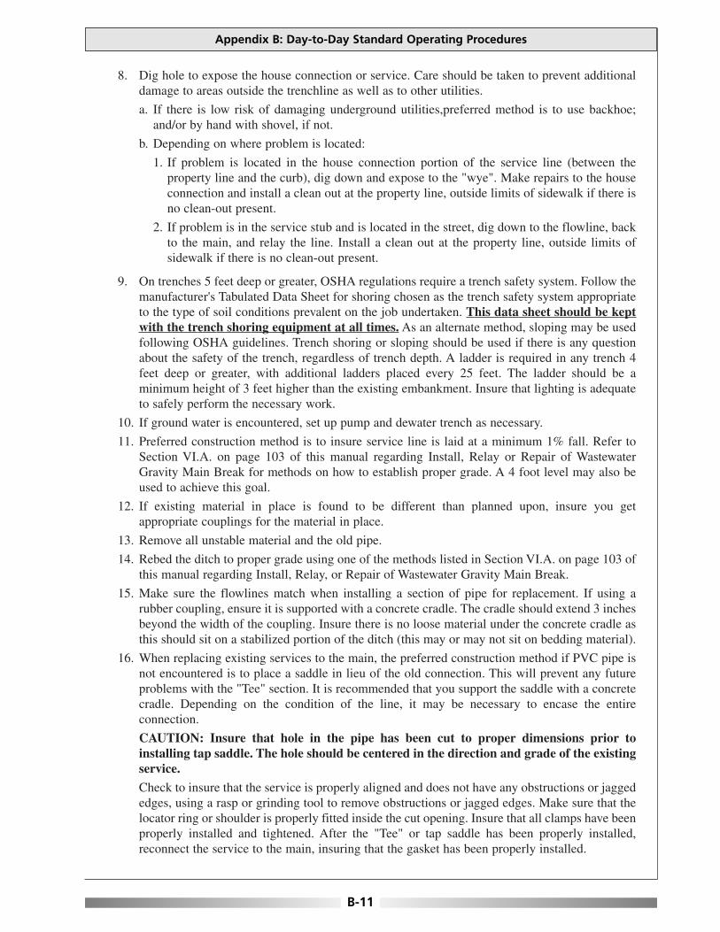
8. Dig hole to expose the house connection or service. Care should be taken to prevent additionaldamage to areas outside the trenchline as well as to other utilities.
a. If there is low risk of damaging underground utilities,preferred method is to use backhoe;and/or by hand with shovel, if not.
b. Depending on where problem is located:
1. If problem is located in the house connection portion of the service line (between theproperty line and the curb), dig down and expose to the "wye". Make repairs to the houseconnection and install a clean out at the property line, outside limits of sidewalk if there isno clean-out present.
2. If problem is in the service stub and is located in the street, dig down to the flowline, backto the main, and relay the line. Install a clean out at the property line, outside limits ofsidewalk if there is no clean-out present.
9. On trenches 5 feet deep or greater, OSHA regulations require a trench safety system. Follow themanufacturer's Tabulated Data Sheet for shoring chosen as the trench safety system appropriateto the type of soil conditions prevalent on the job undertaken. This data sheet should be keptwith the trench shoring equipment at all times. As an alternate method, sloping may be usedfollowing OSHA guidelines. Trench shoring or sloping should be used if there is any questionabout the safety of the trench, regardless of trench depth. A ladder is required in any trench 4feet deep or greater, with additional ladders placed every 25 feet. The ladder should be aminimum height of 3 feet higher than the existing embankment. Insure that lighting is adequateto safely perform the necessary work.
10. If ground water is encountered, set up pump and dewater trench as necessary.
11. Preferred construction method is to insure service line is laid at a minimum 1% fall. Refer toSection VI.A. on page 103 of this manual regarding Install, Relay or Repair of WastewaterGravity Main Break for methods on how to establish proper grade. A 4 foot level may also beused to achieve this goal.
12. If existing material in place is found to be different than planned upon, insure you getappropriate couplings for the material in place.
13. Remove all unstable material and the old pipe.
14. Rebed the ditch to proper grade using one of the methods listed in Section VI.A. on page 103 ofthis manual regarding Install, Relay, or Repair of Wastewater Gravity Main Break.
15. Make sure the flowlines match when installing a section of pipe for replacement. If using arubber coupling, ensure it is supported with a concrete cradle. The cradle should extend 3 inchesbeyond the width of the coupling. Insure there is no loose material under the concrete cradle asthis should sit on a stabilized portion of the ditch (this may or may not sit on bedding material).
16. When replacing existing services to the main, the preferred construction method if PVC pipe isnot encountered is to place a saddle in lieu of the old connection. This will prevent any futureproblems with the "Tee" section. It is recommended that you support the saddle with a concretecradle. Depending on the condition of the line, it may be necessary to encase the entireconnection.
CAUTION: Insure that hole in the pipe has been cut to proper dimensions prior toinstalling tap saddle. The hole should be centered in the direction and grade of the existingservice.
Check to insure that the service is properly aligned and does not have any obstructions or jaggededges, using a rasp or grinding tool to remove obstructions or jagged edges. Make sure that thelocator ring or shoulder is properly fitted inside the cut opening. Insure that all clamps have beenproperly installed and tightened. After the "Tee" or tap saddle has been properly installed,reconnect the service to the main, insuring that the gasket has been properly installed.
Appendix B: Day-to-Day Standard Operating Procedures
B-11

17. Finish laying all pipe. During pipe installation insure that no joints are glued and that all gasketsare properly placed in the bell end. When dealing with a pressurized system or when PVCSchedule 40 pipe is used, insure that restrained, mechanical joints of an acceptable pressurerating are used. Bed and blind pipe. If possible before backfilling pipe, retelevise line to insureall sags have been eliminated and that offset is correct. If scheduling of Camera Crew will notallow pipe to be retelevised before backfilling is complete, schedule this activity as soon aspossible.
18. Bed and backfill pipe according to City of Austin Standard Specifications, Series 500, Pipe andAppurtenances, Section 510, Pipe. This should be done carefully to prevent damage to the newlyplaced pipe.
a. Bed and backfill pipe with gem sand, sand or washed rock in uniform lifts a minimum of 6inches under the pipe to 12 inches or a maximum of 18 inches over the top of the pipe,depending on the depth of the pipe. On temporary repairs, do not use sand bedding material.
b. Lay polywrap or filter fabric over gravel or washed rock to prevent migration of backfill andpossible trench failure.
19. Backfill any trench/subgrade located in right of way with select material, using the UtilityCriteria Manual, Section 5, "Cuts in Public Rights of Way" in uniform layers not exceeding 6inches in depth and tamping each layer in accordance with specifications (95% compaction isrequired).
a. Flexible base placed should be equal to existing material in place or a minimum of 10 inches,whichever is greater. It should be compacted in 6 inch lifts in accordance with specifications(1002 compaction is required) and should be placed to within 2 inches of the existing surface.
b. Apply temporary paving (cold mix) and compact to existing grade.
c. If street is less than two years old, follow Section 5.5.4.E. of the Utility Criteria Manual forCuts in New Streets.
20. Remove spoil, insuring that all contaminated spoils are handled in an appropriate manner andhauled to an approved site for proper disposal. Clean up work site and remove erosion controlsif possible. Always insure that work site is properly cleaned before removing any erosioncontrols. If backfill is behind the curb or in an easement, all areas to receive vegetation shouldbe compacted in 6 inch lifts to 95% compaction, to within 4 inches from finished grade. This canbe accomplished by using a jumping jack, air tamper, or other approved equipment. Dress thearea for vegetation and restore to original condition per stipulations of the General Permit.Maintain erosion controls in place until such time as vegetation has adequately covered disturbedarea. Then remove them per City of Austin Standard Specifications, Series 600 EnvironmentalEnhancement.
21. Remove traffic control devices following the Transportation Criteria Manual, Section 8 onTraffic Control.
Optimizing Operation, Maintenance, and Rehabilitation of Sanitary Sewer Collection Systems
B-12
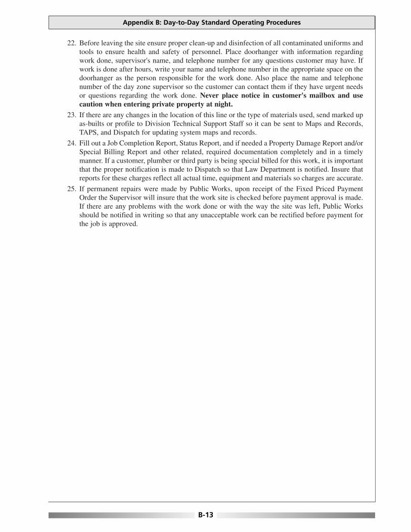
22. Before leaving the site ensure proper clean-up and disinfection of all contaminated uniforms andtools to ensure health and safety of personnel. Place doorhanger with information regardingwork done, supervisor's name, and telephone number for any questions customer may have. Ifwork is done after hours, write your name and telephone number in the appropriate space on thedoorhanger as the person responsible for the work done. Also place the name and telephonenumber of the day zone supervisor so the customer can contact them if they have urgent needsor questions regarding the work done. Never place notice in customer's mailbox and usecaution when entering private property at night.
23. If there are any changes in the location of this line or the type of materials used, send marked upas-builts or profile to Division Technical Support Staff so it can be sent to Maps and Records,TAPS, and Dispatch for updating system maps and records.
24. Fill out a Job Completion Report, Status Report, and if needed a Property Damage Report and/orSpecial Billing Report and other related, required documentation completely and in a timelymanner. If a customer, plumber or third party is being special billed for this work, it is importantthat the proper notification is made to Dispatch so that Law Department is notified. Insure thatreports for these charges reflect all actual time, equipment and materials so charges are accurate.
25. If permanent repairs were made by Public Works, upon receipt of the Fixed Priced PaymentOrder the Supervisor will insure that the work site is checked before payment approval is made.If there are any problems with the work done or with the way the site was left, Public Worksshould be notified in writing so that any unacceptable work can be rectified before payment forthe job is approved.
Appendix B: Day-to-Day Standard Operating Procedures
B-13

This page is intentionally blank.

INSTALL WASTEWATER CLEAN-OUT
Objective: This maintenance activity is performed, if necessary, upon completion of maintenancework done on a wastewater line. The clean-out is installed to allow an access point into the system sothat blockage points may be verified and cleaned out. The clean-out also provides the means to inspectthe customer's tie-in to the system.
It should be noted that contact with raw sewage is a potential health hazard and care should be takento prevent contamination of uniform, skin, or tools by using appropriate personal protective equipmentas may be necessary due to field conditions at the job site. IT IS ESSENTIAL THAT GOODHYGIENE PRACTICES BE USED DURING OPERATIONS AND APPROPRIATE CLEAN-UP AFTER WORK IS COMPLETED TO ENSURE SAFETY.
Personal Safety Equipment:Hard Hat, Back Brace (For Heavy Lifting), Safety Glasses, Full Face Shield,Safety Vests, Work Gloves, Elbow Length Rubber Gloves, Steel Toed Workand/or Rubber Boots, (APR) Respirator, Environmental Coveralls, IsopropylAlcohol, and Ear Protection.
Job Site Safety Equipment:Ladder (Extra Heavy Duty Industrial with IA Duty Rating), Safety Harness,Safety Rope, Gas Detector, Traffic Wand, Traffic Control Devices such asFlags, Flag Stands, Cones Barricades, and Arrowboard, Mesh Safety Fencing,Shoring and/or Trench Box.
Construction Equipment:Backhoe, Jackhammer, Shovels, Tamper, Pipe Beveler, Rasp, and Small HandTools.
Erosion Controls:Sand Bag, Filter Dike and/or Silt Fence.
Construction Materials:Tees, Wyes, Caps, Approved Pipe (appropriate to type of pipe in ground),Rubber Adapters and Stainless Steel Clamps (appropriate to type of materialin ground), Brick or Concrete Support Blocks, Cement as Required, SelectBackfill Materials (flexible base, gem sand, crushed rock, washed rock or twosack flowable fill), 9 mil Polywrap, Poly Tape, Clean Rags, and Cold Mix.
Reference Materials:Tap Cards, As-Builts, Profiles, and Aperture Cards.
Appendix B: Day-to-Day Standard Operating Procedures
B-15

Major tasks and work steps for installing a clean-out:
1. Locate the house connection using information found on the Tap Card. If this information is notavailable, check as-builts or profile, if available. If none of these are available for consultation,use available electronic locating technology to locate the house connection.
2. Analyze the job site. If possible, have all necessary transition pieces on hand at the job site. Setup traffic control following the Transportation Criteria Manual, Section 8 on Traffic Control anderosion control per City of Austin Standard Specifications, Series 600, EnvironmentalEnhancement. The Supervisor or person in charge of the work site will visually inspect siteand insure that documentation is made to record pre-existing conditions. Documentationshould consist of written field notes and photographs with the location, date, and name of theperson documenting the site listed on the back of the photographs. Larger jobs may require useof a video camera to document pre-existing conditions. If it is noted that the street is underconstruction or is new, report this fact and field conditions to Division Technical Support staffby radio or telephone for assistance or possible special billing. Care should be taken to avoidworking in the drip line or root system of protected trees. Notify E.C.S.D. and if possible,property owners should be contacted to advise them of your plans and measures taken to protecttrees.
3. Make a One Call Request and secure a Cut Permit if necessary.
4. Before any work begins, it is mandatory for each crew member in the work zone toproperly wear and maintain all assigned personal safety equipment required for safe jobperformance. This procedure will be strictly enforced on all jobs at all times.
5. If due to depth of the house connection, you find that crew will be working in a confined area;it is essential that you ensure that the atmosphere is regularly checked, using gas detectors toensure the crew's safety. Before entering a confined space, consult the Water and WastewaterUtility Standard Operating Procedure, which establishes guidelines for working in a ConfinedSpace.
6. If necessary, cut sidewalk, driveway, or curb and gutter.
a. Isolate area to be removed. Insure personnel have all appropriate personal safety equipmentin place during this operation.
b. Cut concrete with a jackhammer, quickie saw or hoe ram. Normally, excavation should notproceed until utilities are located and clearance given. However, during emergenciesafter all site preparations are made and erosion controls are in place, with supervisoryapproval hand excavation using extreme caution may begin immediately. Afterunderground utility lines are located, or a maximum wait of two hours, excavation withheavy construction equipment may begin.
7. If necessary, break or cut asphalt/concrete street.
a. The person in charge will make decision to cut rather than break the street; however, cuttingis the preferred construction method. Crew should wear safety glasses and hearing protectionduring breaker operation as well as (APR) respirator and full face shield when using anabrasive saw.
b. Cut asphalt/concrete with an asphalt spade with jackhammer, quickie saw or hoe ram.Normally, excavation should not proceed until utilities are located and clearance given.However, during emergencies after all site preparations are made and erosion controlsare in place, with supervisory approval hand excavation using extreme caution maybegin immediately. After underground utility lines are located, or a maximum wait oftwo hours, excavation with heavy construction equipment may begin.
Optimizing Operation, Maintenance, and Rehabilitation of Sanitary Sewer Collection Systems
B-16

8. Dig hole to expose the house connection or service. Care should be taken to prevent additionaldamage to areas outside the trenchline as well as to other utilities. If there is low risk ofdamaging underground utilities, preferred method is to use backhoe; and/or by hand with shovel,if not.
9. On trenches 5 feet deep or greater, OSHA regulations require a trench safety system. Follow themanufacturer's Tabulated Data Sheet for shoring chosen as the trench safety system appropriateto the type of soil conditions prevalent on the job undertaken. This data sheet should be keptwith the trench shoring equipment at all times. As an alternate method, sloping may be usedfollowing OSHA guidelines. Trench shoring or sloping should be used if there is any questionabout the safety of the trench, regardless of trench depth. A ladder is required in any trench 4feet deep or greater, with additional ladders placed every 25 feet. The ladder should be aminimum height of 3 feet higher than the existing embankment. Insure that lighting is adequateto safely perform the necessary work.
10. Cut the city riser. Install fittings as necessary to make proper connection as per City of AustinStandard Details 520-1 and 520-5. Due to existing field conditions, modifications may need tobe made as necessary to ensure a good connection.
NOTE: Never make a short radius 90 degree turn. Maintain a slow rolling radius byconstructing a 90 degree turn with two 45 degree angle pieces or four 22 1/2 degree bendsif there is enough room. DO NOT USE 90 DEGREE FITTINGS.
11. Tie the customer's service line to the yard line.
12. Bed and backfill pipe according to City of Austin Standard Specifications, Series 500, Pipe andAppurtenances, Section 510, Pipe. This should be done carefully to prevent damage to the newlyplaced connection and clean-out.
13. If applicable, backfill any trench/subgrade located in right of way with select material, using theUtility Criteria Manual, Section 5, "Cuts in Public Rights of clay" in uniform layers notexceeding 6 inches in depth and tamping each layer in accordance with specifications (95%compaction is required).
a. Flexible base placed should be equal to existing material in place or a minimum of 10 inches,whichever is greater. It should be compacted in 6 inch lifts in accordance with specifications(100% compaction is required) and should be placed to within 2 inches of the existing surface.
b. Apply temporary paving (cold mix) and compact to existing grade.
c. If street is less than two years old, follow Section 5.5.4.E. of the Utility Criteria Manual forCuts in New Streets.
14. Remove spoil, insuring that all contaminated spoils are handled in an appropriate manner andhauled to an approved site for proper disposal. Clean up work site and remove erosion controlsif possible. Always insure that work site is properly cleaned before removing any erosioncontrols. If backfill is behind the curb or in an easement, all areas to receive vegetation shouldbe compacted in 6 inch lifts to 95% compaction, to within 4 inches from finished grade. This canbe accomplished by using a jumping jack, air tamper, or other approved equipment. Dress thearea for vegetation and restore to original condition per stipulations of the General Permit.Maintain erosion controls in place until such time as vegetation has adequately covered disturbedarea. Then remove them per City of Austin Standard Specifications, Series 600 EnvironmentalEnhancement.
15. Remove traffic control devices following the Transportation Criteria Manual, Section 8 onTraffic Control.
Appendix B: Day-to-Day Standard Operating Procedures
B-17

16. Before leaving the site ensure proper clean-up and disinfection of all contaminated uniforms andtools to ensure health and safety of personnel. Place doorhanger with information regardingwork done, supervisor's name, and telephone number for any questions customer may have. Ifwork is done after hours, write your name and telephone number in the appropriate space on thedoorhanger as the person responsible for the work done. Also place the name and telephonenumber of the day zone supervisor so the customer can contact them if they have urgent needsor questions regarding the work done. Never place notice in customer's mailbox and usecaution when entering private property at night.
17. If there are any changes in the location of the line or the type of material used, send marked upas-builts or profiles to Division Technical Support Staff so it can be sent to Maps and Records,TAPS and Dispatch for updating system maps and records.
18. Fill out a Job Completion Report, Status Report, and if needed a Property Damage Report and/orSpecial Billing Report and other related, required documentation completely and in a timelymanner. If a customer, plumber or third party is being special billed for this work, it is importantthat the proper notification is made to Dispatch so that Law Department is notified. Insure thatreports for these charges reflect all actual time, equipment and materials so charges are accurate.
19. If permanent repairs were made by Public Works, upon receipt of the Fixed Priced PaymentOrder the Supervisor will insure that the work site is checked before payment approval is made.If there are any problems with the work done or with the way the site was left, Public Worksshould be notified in writing so that any unacceptable work can be rectified before payment forthe job is approved.
Optimizing Operation, Maintenance, and Rehabilitation of Sanitary Sewer Collection Systems
B-18

INSTALL WASTEWATER MANHOLE
Objective: This maintenance activity is performed to provide access to the wastewater system due tothe following: change of pipe size, branch connections, change of grade, or other special conditions.Manholes should be no farther than 500 feet apart.
It should be noted that contact with raw sewage is a potential health hazard and care should be takento prevent contamination of uniform, skin, or tools by using appropriate personal protective equipmentas may be necessary due to field conditions at the job site. IT IS ESSENTIAL THAT GOODHYGIENE PRACTICES BE USED DURING OPERATIONS AND APPROPRIATE CLEAN-UP AFTER WORK IS COMPLETED TO ENSURE SAFETY.
Personal Safety Equipment:Hard Hat, Back Brace (For Heavy Lifting), Safety Glasses, Full Face Shield,Safety Vests, Work Gloves, Elbow Length Rubber Gloves, Steel Toed Workand/or Rubber Boots, (APR) Respirator, Environmental Coveralls, IsopropylAlcohol, and Ear Protection.
Job Site SafetyEquipment:Ladder (Extra Heavy Duty Industrial with IA Duty Rating), Safety Harness,Safety Rope, Gas Detector, Traffic Wand, Traffic Control Devices such asFlags, Flag Stands, Cones Barricades, and Arrowboard, Mesh Safety Fencing,Shoring and/or Trench Box.
Construction Equipment:
Backhoe, Jackhammer, Shovels, Hydrant Wrench, Water Pump, Suction andDischarge Hoses, Pipe Cutter (appropriate to material in ground), Wrenches,Tamper, Air Compressor, Laser, Surveyor’s Level, String Line, Batter Board,Transit, Philadelphia Rod (Grade Rod), Pipe Beveler, Rasp, Trowel, SmallHand Tools, Chain, Sling, Jute, Air Plugs or Wing Plugs, Steel Plates,Generator with GFCI, Flood Lights, Hand Lights, Drop Lights with HeavyDuty Bulb U.A. Rated Explosion Proof, 5 Ton Crane, and Lift Truck.
Erosion Controls:Sand Bag, Filter Dike and/or Silt Fence.
Construction Materials:Approved Manhole Sections, Approved Pipe (appropriate to type of pipe inground), Appropriate Ring and Cover, Grade Rings (Donuts), Stainless SteelClamps (appropriate to type of material in ground), Rubber Gaskets, Sleeves,Joint Lubricant, Brick or Concrete Support Blocks, Concrete or Cement asRequired, Select Backfill Materials (flexible base, gem sand, crushed rock,washed rock or two sack flowable fill), 9 mil Polywrap, Poly Tape, CleanRags, and Cold Mix.
Reference Materials:Quads, As-Builts, Profiles, and Aperture Cards.
Appendix B: Day-to-Day Standard Operating Procedures
B-19
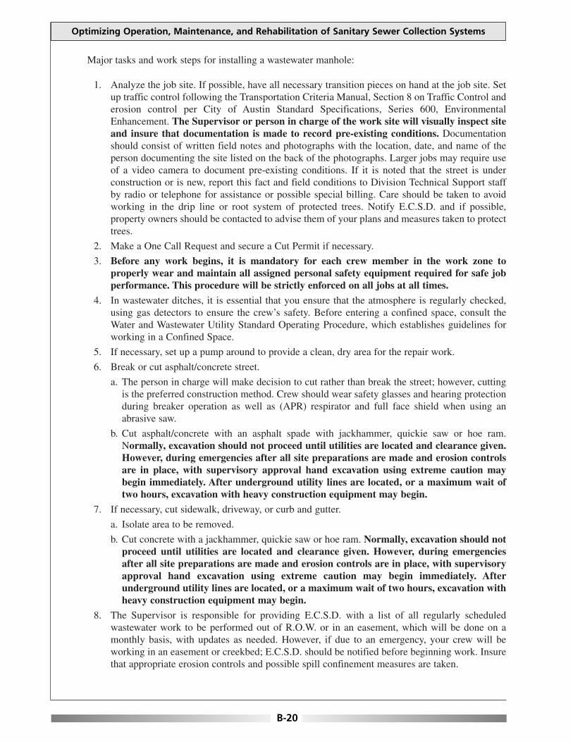
Major tasks and work steps for installing a wastewater manhole:
1. Analyze the job site. If possible, have all necessary transition pieces on hand at the job site. Setup traffic control following the Transportation Criteria Manual, Section 8 on Traffic Control anderosion control per City of Austin Standard Specifications, Series 600, EnvironmentalEnhancement. The Supervisor or person in charge of the work site will visually inspect siteand insure that documentation is made to record pre-existing conditions. Documentationshould consist of written field notes and photographs with the location, date, and name of theperson documenting the site listed on the back of the photographs. Larger jobs may require useof a video camera to document pre-existing conditions. If it is noted that the street is underconstruction or is new, report this fact and field conditions to Division Technical Support staffby radio or telephone for assistance or possible special billing. Care should be taken to avoidworking in the drip line or root system of protected trees. Notify E.C.S.D. and if possible,property owners should be contacted to advise them of your plans and measures taken to protecttrees.
2. Make a One Call Request and secure a Cut Permit if necessary.
3. Before any work begins, it is mandatory for each crew member in the work zone toproperly wear and maintain all assigned personal safety equipment required for safe jobperformance. This procedure will be strictly enforced on all jobs at all times.
4. In wastewater ditches, it is essential that you ensure that the atmosphere is regularly checked,using gas detectors to ensure the crew’s safety. Before entering a confined space, consult theWater and Wastewater Utility Standard Operating Procedure, which establishes guidelines forworking in a Confined Space.
5. If necessary, set up a pump around to provide a clean, dry area for the repair work.
6. Break or cut asphalt/concrete street.
a. The person in charge will make decision to cut rather than break the street; however, cuttingis the preferred construction method. Crew should wear safety glasses and hearing protectionduring breaker operation as well as (APR) respirator and full face shield when using anabrasive saw.
b. Cut asphalt/concrete with an asphalt spade with jackhammer, quickie saw or hoe ram.Normally, excavation should not proceed until utilities are located and clearance given.However, during emergencies after all site preparations are made and erosion controlsare in place, with supervisory approval hand excavation using extreme caution maybegin immediately. After underground utility lines are located, or a maximum wait oftwo hours, excavation with heavy construction equipment may begin.
7. If necessary, cut sidewalk, driveway, or curb and gutter.
a. Isolate area to be removed.
b. Cut concrete with a jackhammer, quickie saw or hoe ram. Normally, excavation should notproceed until utilities are located and clearance given. However, during emergenciesafter all site preparations are made and erosion controls are in place, with supervisoryapproval hand excavation using extreme caution may begin immediately. Afterunderground utility lines are located, or a maximum wait of two hours, excavation withheavy construction equipment may begin.
8. The Supervisor is responsible for providing E.C.S.D. with a list of all regularly scheduledwastewater work to be performed out of R.O.W. or in an easement, which will be done on amonthly basis, with updates as needed. However, if due to an emergency, your crew will beworking in an easement or creekbed; E.C.S.D. should be notified before beginning work. Insurethat appropriate erosion controls and possible spill confinement measures are taken.
Optimizing Operation, Maintenance, and Rehabilitation of Sanitary Sewer Collection Systems
B-20

9. Install wastewater manholes per City of Austin Standard Details 506-1, 506-5, 506-7, 506-8,506-9, or 506-10 as applicable.
10. Excavate a minimum of 12 inches below the outside diameter (O.D.) of the existing main. Careshould be taken to prevent additional damage to areas outside the trenchline. If there is low riskof damaging underground utilities, preferred construction method is to use backhoe; and/orexcavate by hand with shovel, if not.
11. On trenches 5 feet deep or greater, OSHA regulations require a trench safety system. Follow themanufacturer’s Tabulated Data Sheet for shoring chosen as the trench safety system appropriateto the type of soil conditions prevalent on the job undertaken. This data sheet should be keptwith the trench shoring equipment at all times. As an alternate method, sloping may be usedfollowing OSHA guidelines. Trench shoring or sloping should be used if there is any questionabout the safety of the trench, regardless of trench depth. A ladder is required in any trench 4feet deep or greater, with additional ladders placed every 25 feet. The ladder should be aminimum height of 3 feet higher than the existing embankment. Insure that lighting is adequateto safely perform the necessary work.
12. If ground water is encountered, set up pump and dewater trench as necessary.
13. Establish a method of maintaining proper grade. Refer to Section VI.A. of this manual regardingInstall, Relay or Repair of Wastewater Gravity Main Break on page 103 of this manual, whichestablishes methodology for maintaining proper grade.
14. Build manhole invert at the proper elevation. Preferred construction method is to maintain aminimum 0.10 foot (approximately 1.25 inches) fall through the manhole, when possible.Otherwise, follow the slope of the pipe.
15. The pipe coming into the manhole should be supported with bricks, ensuring that these arelocated outside the perimeter of the manhole base. The manhole base should have an insidediameter of 4 feet and an outside diameter of 6 feet. This can be achieved by marking the centerpoint with a nail and scribing a 2 foot radius.
16. The concrete should be a minimum of 8 inches thick below the bottom of the outside diameterof the pipe. The roll of the invert should be half the diameter of the pipe with a slight tapertoward the edge. Keep the invert the same diameter as the pipe, and never "Tee" in straight. Thereshould be no hard corners—always smooth corners with a smooth trowel finish. As aconstruction guide, follow Standard Detail 506-9.
17. Where field conditions will allow, precast base sections can be used as approved on the Utility’sStandard Product List. All manhole bases constructed in place should be constructed with ClassA concrete with a 2 to 3 inch slump maximum (a stiff, dry mix). Curing time of 72 hours shouldelapse before manhole sections are stacked on the base, unless high early strength concrete isused, for which curing time will be a minimum of 12 hours.
18. After curing time has elapsed, make a mortar mix (a sand and cement mix) with proportions of3:1 (i.e. 3 parts sand to 1 part cement). This will be a stiff mix used as a sealant on interior andexterior walls of the manhole and at the seams of the foundation. Begin stacking precast sectionsor building sections with brick. The first section of the manhole should be set on 1 inch of theprepared mortar mix, which has been placed on the concrete base. After the first section has beenplaced on the mortar mix, subsequent sections will be stacked before mortar hardens. T h e s ejoints will be gasketed (not mortared) in place. Then go back and rewipe the bottom section withthe mortar mix at the foundation to ensure a good seal.
19. All subsequent gasketed joints should be sealed by liberally lubricating and installing anappropriate "0 Ring". Lubricate the groove and bottom of each subsequent joint with pipe soap.Ensure safe construction practices are observed when stacking manhole sections in place.Backfill should take place as each section is installed. Bed and backfill pipe according to City ofAustin Standard Specifications, Series 500, Pipe and Appurtenances, Section 510, Pipe. Thisshould be done carefully to prevent damage to the newly constructed manhole.
Appendix B: Day-to-Day Standard Operating Procedures
B-21

Optimizing Operation, Maintenance, and Rehabilitation of Sanitary Sewer Collection Systems
B-22
20. Install rings and cone sections as necessary, measuring from existing pavement or groundelevation. Try to set top of cone within 6 inches of grade or within a maximum of 12 inches onnew construction, following Std. No. 504-2.
21. If applicable, backfill any trench/subgrade located in right of way with select material, using theUtility Criteria Manual, Section 5, ‘Cuts in Public Rights of Way" in uniform layers notexceeding 6 inches in depth and tamping each layer in accordance with specifications (95%compaction is required).
a. Flexible base placed should be equal to existing material in place or a minimum of 10 inches,whichever is greater. It should be compacted in 6 inch lifts in accordance with specifications(100% compaction is required) and should be placed to within 2 inches of the existing surface.
b. Apply temporary paving (cold mix) and compact to existing grade.
c. If street is less than two years old, follow Section 5.5.4.E. of the Utility Criteria Manual forCuts in New Streets.
22. Mortar ring and cover and wipe the chimney inside and out on all grade rings (donuts) used inadjustment of castings.
23. Do not subject manhole to traffic for at least 12 hours. This may be plated off or barricaded,depending upon location and traffic.
24. Remove spoil, insuring that all contaminated spoils are handled in an appropriate manner andhauled to an approved site for proper disposal. Clean up work site and remove erosion controlsif possible. Always insure that work site is properly cleaned before removing any erosioncontrols. If backfill is behind the curb or in an easement, all areas to receive vegetation shouldbe compacted in 6 inch lifts to 95% compaction, to within 4 inches from finished grade. This canbe accomplished by using a jumping jack, air tamper, or other approved equipment. Dress thearea for vegetation and restore to original condition per stipulations of the General Permit.Maintain erosion controls in place until such time as vegetation has adequately covered disturbedarea. Then remove them per City of Austin Standard Specifications, Series 600 EnvironmentalEnhancement.
25. Remove traffic control devices following the Transportation Criteria Manual, Section 8 onTraffic Control.
26. Before leaving the site ensure proper clean-up and disinfection of all contaminated uniforms andtools to ensure health and safety of personnel. Place doorhanger with information regardingwork done, supervisor’s name, and telephone number for any questions customer may have. Ifwork is done after hours, write your name and telephone number in the appropriate space on thedoorhanger as the person responsible for the work done. Also place the name and telephonenumber of the day zone supervisor so the customer can contact them if they have urgent needsor questions regarding the work done. Never place notice in customer’s mailbox and usecaution when entering private property at night.
27. If there are any changes in the location of the line, the type of material used, or a new manholebuilt, send marked up as-builts or profiles to Division Technical Support Staff so it can be sentto Maps and Records, TAPS and Dispatch for updating system maps and records.
28. Fill out a Job Completion Report, Status Report, and if needed a Property Damage Report and/orSpecial Billing Report and other related, required documentation completely and in a timelymanner. If a customer, plumber or third party is being special billed for this work, it is importantthat the proper notification is made to Dispatch so that Law Department is notified. Insure thatreports for these charges reflect all actual time, equipment and materials so charges are accurate.
29. If permanent repairs were made by Public Works, upon receipt of the Fixed Priced PaymentOrder the Supervisor will insure that the work site is checked before payment approval is made.If there are any problems with the work done or with the way the site was left, Public Worksshould be notified in writing so that any unacceptable work can be rectified before payment forthe job is approved.

REPAIR OF WASTEWATER MANHOLE
Objective: This maintenance activity is performed to repair manholes which have been damaged.Typical repairs made to manholes are to cracked bases, tie-ins to an existing manhole, adjustments tomanholes that exceed 2 foot allowable ring adjustment, coating the inside, or resealing or replacing aring and cover. These are caused by infiltration or leaks due to erosion, soil movement, corrosion dueto chemical or sulfide damage, improper construction or repair, or combinations of any of the above.
It should be noted that contact with raw sewage is a potential health hazard and care should be takento prevent contamination of uniform, skin, or tools by using appropriate personal protective equipmentas may be necessary due to field conditions at the job site. IT IS ESSENTIAL THAT GOODHYGIENE PRACTICES BE USED DURING OPERATIONS AND APPROPRIATE CLEAN-UP AFTER WORK IS COMPLETED TO ENSURE SAFETY.
Personal Safety Equipment:Hard Hat, Back Brace (For Heavy Lifting), Safety Glasses, Full Face Shield,Safety Vests, Work Gloves, Elbow Length Rubber Gloves, Steel Toed Workand/or Rubber Boots, (APR) Respirator, Environmental Coveralls, IsopropylAlcohol, and Ear Protection.
Job Site Safety Equipment:Ladder (Extra Heavy Duty Industrial with IA Duty Rating), Safety Harness,Safety Rope, Gas Detector, Traffic Wand, Traffic Control Devices such asFlags, Flag Stands, Cones Barricades, and Arrowboard, Mesh Safety Fencing,Shoring and/or Trench Box.
Construction Equipment:Backhoe, Jackhammer, Shovels, Hydrant Wrench, Water Pump, Suction andDischarge Hoses, Pipe Cutter (appropriate to material in ground), Wrenches,Tamper, Air Compressor, Laser, Surveyor's Level, String Line, Batter Board,Transit, Philadelphia Rod (Grade Rod), Pipe Beveler, Rasp, Trowel, SmallHand Tools, Chain, Sling, Jute, Air Plugs or Wing Plugs, Steel Plates,Generator with GFCI, Flood Lights, Hand Lights, Drop Lights with HeavyDuty Bulb U.A. Rated Explosion Proof, 5 Ton Crane, and Lift Truck.
Erosion Controls:Sand Bag, Filter Dike and/or Silt Fence.
Construction Materials:Approved Manhole Sections, Approved Pipe (appropriate to type of pipe inground), Appropriate Ring and Cover, Grade Rings (Donuts), Stainless SteelClamps (appropriate to type of material in ground), Rubber Gaskets, Sleeves,Joint Lubricant, Brick or Concrete Support Blocks, Concrete or Cement asRequired, Select Backfill Materials (flexible base, gem sand, crushed rock,washed rock or two sack flowable fill), 9 mil Polywrap, Poly Tape, CleanRags, and Cold Mix.
Reference Materials:Quads, As-Builts, Profiles, and Aperture Cards.
Appendix B: Day-to-Day Standard Operating Procedures
B-23

Major tasks and work steps for repairing a wastewater manhole:
1. Analyze the job site. If possible, have all necessary materials on hand at the job site. Set uptraffic control following the Transportation Criteria Manual, Section 8 on Traffic Control anderosion control per City of Austin Standard Specifications, Series 600, EnvironmentalEnhancement. The Supervisor or person in charge of the work site will visually inspect siteand insure that documentation is made to record pre-existing conditions. Documentationshould consist of written field notes and photographs with the location, date, and name of theperson documenting the site listed on the back of the photographs. Larger jobs may require useof a video camera to document pre-existing conditions. If it is noted that the street is underconstruction or is new, report this fact and field conditions to Division Technical Support staffby radio or telephone for assistance or possible special billing. Care should be taken to avoidworking in the drip line or root system of protected trees. Notify E.C.S.D. and if possible,property owners should be contacted to advise them of your plans and measures taken to protecttrees.
2. Make a One Call Request and secure a Cut Permit if necessary.
3. Before any work begins, it is mandatory for each crew member in the work zone toproperly wear and maintain all assigned personal safety equipment required for safe jobperformance. This procedure will be strictly enforced on all jobs at all times.
4. In wastewater ditches, it is essential that you ensure that the atmosphere is regularly checked,using gas detectors to ensure the crew's safety. Before entering a confined space, consult theWater and Wastewater Utility Standard Operating Procedure, which establishes guidelines forworking in a Confined Space.
5. If possible, isolate manhole by diverting the flow. If necessary, set up a pump around to providea clean, dry area for the repair work.
6. If necessary to break or cut asphalt/concrete street:
a. The person in charge will make decision to cut rather than break the street; however, cuttingis the preferred construction method. Crew should wear safety glasses and hearing protectionduring breaker operation as well as (APR) respirator and full face shield when using anabrasive saw.
b. Cut asphalt/concrete with an asphalt spade with jackhammer, quickie saw or hoe ram.Normally, excavation should not proceed until utilities are located and clearance given.However, during emergencies after all site preparations are made and erosion controlsare in place, with supervisory approval hand excavation using extreme caution maybegin immediately. After underground utility lines are located, or a maximum wait oftwo hours, excavation with heavy construction equipment may begin.
7. If necessary to cut sidewalk, driveway, or curb and gutter.
a. Isolate area to be removed.
b. Cut concrete with a jackhammer, quickie saw or hoe ram. Normally, excavation should notproceed until utilities are located and clearance given. However, during emergenciesafter all site preparations are made and erosion controls are in place, with supervisoryapproval hand excavation using extreme caution may begin immediately. Afterunderground utility lines are located, or a maximum wait of two hours, excavation withheavy construction equipment may begin.
8. The Supervisor is responsible for providing E.C.S.D. with a list of all regularly scheduledwastewater work to be performed out of R.O.W. or in an easement, which will be done on amonthly basis, with updates as needed. However, if due to an emergency, your crew will beworking in an easement or creekbed; E.C.S.D. should be notified before beginning work. Insurethat appropriate erosion controls and possible spill confinement measures are taken.
Optimizing Operation, Maintenance, and Rehabilitation of Sanitary Sewer Collection Systems
B-24

9. For repairs to manhole bottoms, the following should be done:
a. Thoroughly clean the area (down to sound concrete) with a high pressure spray, removing allgrease or damaging chemicals.
b. Prepare a mortar mix and repair or reshape the bottom of the base of the invert with the mortarmix (prepared, as always, with potable water). This should be a dry mix shaped to the bottom.Try to maintain a minimum 0.10 foot (approximately 1.25 inches) fall through the manhole,when possible. Otherwise, follow the slope of the pipe. Form a flow channel, creating asmooth flow line. Never "Tee" in straight. There should be no hard corners--always smoothcorners with a smooth trowel finish.
c. Seal around all pipe connections, using quickset mortar, and cure for at least 4 hours beforeopening manhole to flow.
10. For tie-ins, the following should be done:
a. The preferred method is to scribe a circle on the outside of the manhole at the proper elevationand location.
b. Drill 1/2 inch diameter holes around the circumference of the scribed line of the pipe 2 incheson center.
c. Chip holes out and remove the plug with care so as not to damage the manhole section. Thiscan be done by using a chipping hammer or jackhammer.
d. Enter manhole and chip or rough-cut a flow channel for the new line or build the channel outof brick and mortar.
e. Channelize invert to accommodate the new pipe.
11. Brick may be used as a filler or for structural integrity, as needed.
12. For adjustments to manholes that exceed the 2 foot allowable ring adjustment, the followingshould be done:
a. Saw cut the pavement by marking an 8 1/2 foot square around the top of the manhole,centered on the manhole.
b. Break and remove the asphalt with a jackhammer or hoe ram.
c. Begin to excavate down the side of the manhole to 1 foot below the cone section.
d. Remove the ring and cover and any adjustment grade rings (donuts).
e. Safely remove the cone section with an approved method such as wedging a steel beam insidethe cone section or by using an approved lifting device. Tie a chain or 3/4 inch cable sling tothe steel beam (or whatever you used to wedge inside the cone section). Attach chain or slingto the lifting device (lift truck, backhoe, etc.). If using a backboom on a backhoe to lift, weightthe front with sufficient ballast to insure backhoe will not be pulled over by the forceexercised when lifting begins
f. Pull the cone section out and remove it from the manhole.
g. Clean the spigot end, removing any old mortar or debris.
h. Preferred construction method is to install a new gasket. If a proper gasket is not available,clean the seam and remortar as you set the new section.
i. If new section dimensions are not the same as the old section in place, or if the groove doesnot match up, mortar a new section riser of the appropriate length in place.
j. Replace cone section with new gasket or mortar it in place. Reinstall ring and cover usingadjusting grade rings (donuts) as necessary to bring top of manhole to finish grade.
k. If existing ring and cover is bolted using 9/16 inch bolts, ring and cover should be replacedwith new approved 15/16 inch bolted ring and cover.
1. Insure all adjusting grade rings are wiped inside and out with an approved mortar mix. Allowthe mortar mix to cure as long as possible before beginning backfill operations.
Appendix B: Day-to-Day Standard Operating Procedures
B-25

m. Backfill any trench/subgrade located in right of way with select material, using the UtilityCriteria Manual, Section 5, "Cuts in Public Rights of Way" in uniform layers not exceeding 6inches in depth and tamping each layer in accordance with specifications (95% compaction isrequired).
1. Flexible base placed should be equal to existing material in place or a minimum of 10inches, whichever is greater. It should be compacted in 6 inch lifts in accordance withspecifications (100% compaction is required) and should be placed to within 2 inches ofthe existing surface.
2. Apply temporary paving (cold mix) and compact to existing grade.
3. If street is less than two years old, follow Section 5.5.4.E. of the Utility Criteria Manual forCuts in New Streets.
n. Do not subject manhole to traffic for at least 12 hours. This may be plated off or barricaded,depending upon location and traffic.
13. Coating manholes is a maintenance task which is currently being performed by contract labor.
14. For resealing or replacing ring and cover, the following should be done:
a. If existing ring and cover is still serviceable, temporarily remove it so that all old grout andmortar mix can be removed from the top of the cone section and ring.
b. Thoroughly clean this section, using a brush, small chisel, and hammer. Insure surface is cleanbefore covering the top of the cone section.
c. Place a minimum 1 inch thick bead of mortar (use enough to bring section to finish grade).
d. Rewipe ring with generous amount of mortar and mound it around the edge.
e. Set the ring, insuring it comes to the top and sloping it to the outside edge of the cone section.If this is placed in the street or a paved alley, leave the mortar down 2 to 3 inches, or thethickness of the existing pavement.
f. If this is placed in any other area (creekbed, right of way, etc.), use a bolted ring and cover.
15. Once the above referenced tasks have been completed, follow standard operating procedures byremoving spoil, insuring that all contaminated spoils are handled in an appropriate manner andhauled to an approved site for proper disposal. Clean up work site and remove erosion controlsif possible. Always insure that work site is properly cleaned before removing any erosioncontrols. If backfill is behind the curb or in an easement, all areas to receive vegetation shouldbe compacted in 6 inch lifts to 95% compaction, to within 4 inches from finished grade. This canbe accomplished by using a jumping jack, air tamper, or other approved equipment. Dress thearea for vegetation and restore to original condition per stipulations of the General Permit.Maintain erosion controls in place until such time as vegetation has adequately covered disturbedarea. Then remove them per City of Austin Standard Specifications, Series 600 EnvironmentalEnhancement.
16. Remove traffic control devices following the Transportation Criteria Manual, Section 8 onTraffic Control.
17. Before leaving the site ensure proper clean-up and disinfection of all contaminated uniforms andtools to ensure health and safety of personnel. Place doorhanger with information regardingwork done, supervisor's name, and telephone number for any questions customer may have. Ifwork is done after hours, write your name and telephone number in the appropriate space on thedoorhanger as the person responsible for the work done. Also place the name and telephonenumber of the day zone supervisor so the customer can contact them if they have urgent needsor questions regarding the work done. Never place notice in customer's mailbox and usecaution when entering private property at night.
18. If there are any changes in the location of the line, the type of material used, or a new connectionto the manhole; send marked up as-builts or profiles to Division Technical Support staff so it canbe sent to Maps and Records, TAPS and Dispatch for updating system maps and records.
Optimizing Operation, Maintenance, and Rehabilitation of Sanitary Sewer Collection Systems
B-26

19. Fill out a Job Completion Report, Status Report, and if needed a Property Damage Report and/orSpecial Billing Report and other related, required documentation completely and in a timelymanner. If a customer, plumber or third party is being special billed for this work, it is importantthat the proper notification is made to Dispatch so that Law Department is notified. Insure thatreports for these charges reflect all actual time, equipment and materials so charges are accurate.
20. If permanent repairs were made by Public Works, upon receipt of the Fixed Priced PaymentOrder the Supervisor will insure that the work site is checked before payment approval is made.If there are any problems with the work done or with the way the site was left, Public Worksshould be notified in writing so that any unacceptable work can be rectified before payment forthe job is approved.
Appendix B: Day-to-Day Standard Operating Procedures
B-27

This page is intentionally blank.
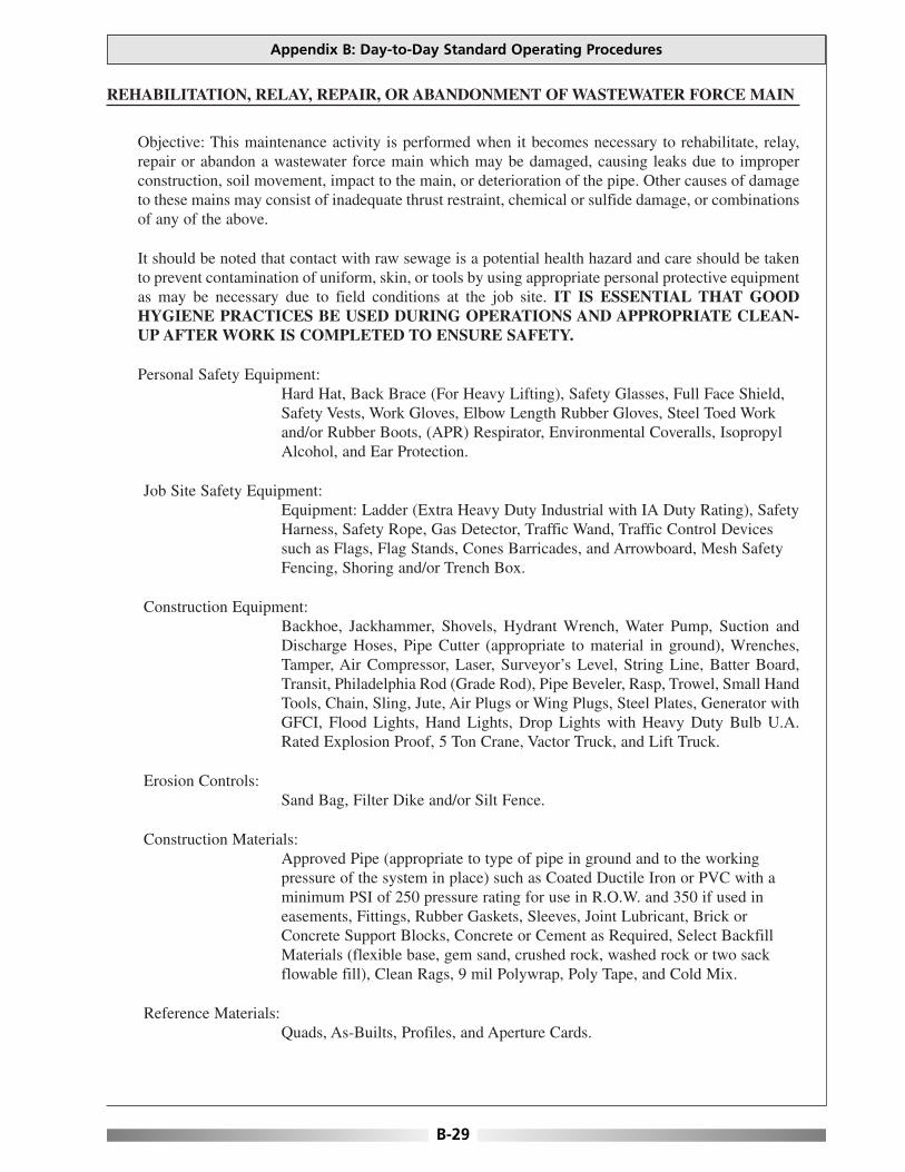
REHABILITATION, RELAY, REPAIR, OR ABANDONMENT OF WASTEWATER FORCE MAIN
Objective: This maintenance activity is performed when it becomes necessary to rehabilitate, relay,repair or abandon a wastewater force main which may be damaged, causing leaks due to improperconstruction, soil movement, impact to the main, or deterioration of the pipe. Other causes of damageto these mains may consist of inadequate thrust restraint, chemical or sulfide damage, or combinationsof any of the above.
It should be noted that contact with raw sewage is a potential health hazard and care should be takento prevent contamination of uniform, skin, or tools by using appropriate personal protective equipmentas may be necessary due to field conditions at the job site. IT IS ESSENTIAL THAT GOODHYGIENE PRACTICES BE USED DURING OPERATIONS AND APPROPRIATE CLEAN-UP AFTER WORK IS COMPLETED TO ENSURE SAFETY.
Personal Safety Equipment:Hard Hat, Back Brace (For Heavy Lifting), Safety Glasses, Full Face Shield,Safety Vests, Work Gloves, Elbow Length Rubber Gloves, Steel Toed Workand/or Rubber Boots, (APR) Respirator, Environmental Coveralls, IsopropylAlcohol, and Ear Protection.
Job Site Safety Equipment:Equipment: Ladder (Extra Heavy Duty Industrial with IA Duty Rating), SafetyHarness, Safety Rope, Gas Detector, Traffic Wand, Traffic Control Devicessuch as Flags, Flag Stands, Cones Barricades, and Arrowboard, Mesh SafetyFencing, Shoring and/or Trench Box.
Construction Equipment:Backhoe, Jackhammer, Shovels, Hydrant Wrench, Water Pump, Suction andDischarge Hoses, Pipe Cutter (appropriate to material in ground), Wrenches,Tamper, Air Compressor, Laser, Surveyor’s Level, String Line, Batter Board,Transit, Philadelphia Rod (Grade Rod), Pipe Beveler, Rasp, Trowel, Small HandTools, Chain, Sling, Jute, Air Plugs or Wing Plugs, Steel Plates, Generator withGFCI, Flood Lights, Hand Lights, Drop Lights with Heavy Duty Bulb U.A.Rated Explosion Proof, 5 Ton Crane, Vactor Truck, and Lift Truck.
Erosion Controls:Sand Bag, Filter Dike and/or Silt Fence.
Construction Materials:Approved Pipe (appropriate to type of pipe in ground and to the workingpressure of the system in place) such as Coated Ductile Iron or PVC with aminimum PSI of 250 pressure rating for use in R.O.W. and 350 if used ineasements, Fittings, Rubber Gaskets, Sleeves, Joint Lubricant, Brick orConcrete Support Blocks, Concrete or Cement as Required, Select BackfillMaterials (flexible base, gem sand, crushed rock, washed rock or two sackflowable fill), Clean Rags, 9 mil Polywrap, Poly Tape, and Cold Mix.
Reference Materials:Quads, As-Builts, Profiles, and Aperture Cards.
Appendix B: Day-to-Day Standard Operating Procedures
B-29
Major tasks and work steps for rehabilitation, relay, repair or abandonment of a wastewater force main:
1. If possible, coordinate and schedule the shut down of the lift station prior to containment andrepair with Division Technical Support staff during regular working hours and with Dispatchafter hours, weekends, and holidays. NOTE: If you determine or suspect through records orvisual inspection a restrained joint system is in place, refer to Section I.D. on page 18 of thismanual regarding Installation of Restraint Systems.
2. Analyze the job site. If possible, have all necessary materials on hand at the job site. Set uptraffic control following the Transportation Criteria Manual, Section 8 on Traffic Control anderosion control per City of Austin Standard Specifications, Series 600, EnvironmentalEnhancement. The Supervisor or person in charge of the work site will visually inspect siteand insure that documentation is made to record pre-existing conditions. Documentationshould consist of written field notes and photographs with the location, date, and name of theperson documenting the site listed on the back of the photographs. Larger jobs may require useof a video camera to document pre-existing conditions. If it is noted that the street is underconstruction or is new, report this fact and field conditions to Division Technical Support staffby radio or telephone for assistance or possible special billing. Care should be taken to avoidworking in the drip line or root system of protected trees. Notify E.C.S.D. and if possible,property owners should be contacted to advise them of your plans and measures taken to protecttrees. Contain any wastewater spillage as quickly as possible by setting up a pump around, ifpossible, or by calling in pump trucks to haul effluent to approved disposal sites.
3. Make a One Call Request and secure a Cut Permit, if necessary.
4. Before any work begins, it is mandatory for each crew member in the work zone toproperly wear and maintain all assigned personal safety equipment required for safe jobperformance. This procedure will be strictly enforced on all jobs at all times.
5. Dig hole to expose main. Care should be taken to prevent additional damage to areas outside thetrenchline.
a. If there is low risk of damaging underground utilities, preferred method is to use backhoe;and/or by hand with shovel, if not.
b. Trench should extend at least 12 inches below damaged or broken pipe.
6. On trenches 5 feet deep or greater, OSHA regulations require a trench safety system. Follow themanufacturer’s Tabulated Data Sheet for shoring chosen as the trench safety system appropriateto the type of soil conditions prevalent on the job undertaken. This data sheet should be keptwith the trench shoring equipment at all times. As an alternate method, sloping may be usedfollowing OSHA guidelines. . Trench shoring or sloping should be used if there is any questionabout the safety of the trench, regardless of trench depth. A ladder is required in any trench 4feet deep or greater, with additional ladders placed every 25 feet. The ladder should be aminimum height of 3 feet higher than the existing embankment. Insure that lighting is adequateto safely perform the necessary work.
7. Locate the break(s) in the wastewater force main. If leak cannot be visually detected, contactLeak Detection personnel for assistance.
8. Determine type of break (beam, split, corrosion, blow-out, etc.).
9. Request repair material from the pipe yard if item is not available on maintenance truck.Supervisor may have to make arrangements to have material(s) picked up and delivered to thesite.
10. Make the appropriate repair.
a. If the area to be repaired is small enough, the preferred method of repair is to cut in a nipple (a3 foot minimum length is required) and use two sleeves. An alternate repair method is to use arepair clamp, if rehabilitation is scheduled within 3 years or when making temporary repairs to
Optimizing Operation, Maintenance, and Rehabilitation of Sanitary Sewer Collection Systems
B-30

keep the public in service until permanent repairs can be made. Thoroughly clean the section ofthe pipe to which the sleeves/clamp will be applied and install the sleeves/clamp, making surethat the pipe surface is as smooth as possible. Insure that even pressure is applied to the clampingbolts to get a good seal.
b. If the line to be repaired is C900 PVC, Cast Iron, or Ductile Iron; and the line is split:
1. Cut out damaged section at least one foot past the split area and clean the pipe ends to befitted. Always wear safety glasses, hearing protection, full face shield, and an (APR)respirator when using any saw or cutting tool!
2. Measure the section of pipe to be replaced.
3. Measure and cut Ductile Iron or C900 PVC replacement pipe. Any metal components needto be wrapped with 9 mil polywrap. Insure that polywrap is sealed and secured on the endwith poly tape. At this time a field determination needs to be made whether a restraintsystem is required or not.
4. Place restraints if needed. Refer to Section I.D. on page 18 of this manual regardingInstallation of Restraint Systems, then place glands or followers on ends of replacementpipe and on pipe ends to be fitted.
5. Center sleeves and seat gasket on both ends of each sleeve, making sure that the taperedend of the gasket is towards the fitting.
6. Slide retainers into place and tighten bolts. Bolts must be tightened in a consistent mannerso that an even constant pressure is maintained on the gasket. Failure to take the time totighten bolts evenly, using a crisscross pattern, can result in a subsequent main failure. It isimportant to use the manufacturer’s recommended torque, and do not tighten bolts toomuch to avoid breaking the follower.
c. Concrete Steel Cylinder: Solicit and follow the pipe manufacturer’s recommendations forrepair. The preferred method is to use a weld-on saddle. The size of the saddle should bedetermined in the field. If the break is larger than the available weld-on saddle, a plate withsaddle can be welded onto the pipe and the tensioning rods welded back into place over theplate. Finish repair by remortaring pipe inside and out and using a diaper as needed.
d. Asbestos Cement (AC): Before beginning repairs on A/C pipe, consult the Water andWastewater Utility Standard Operating Procedure A-3.
e. In all cases it is important that the pipe interior is protected from entry of animals, rags, andany other extraneous solids. Any materials that may enter the main should be removedimmediately, before they get further into the line and cannot be removed. Rags and otherforeign materials allowed to remain in the line during a repair can later clog up services orcause other problems such as a reduction in flow capacity or an increase in the head that mustbe overcome by the pumps.
f. Documentation of type of repair and materials used should be given to Division TechnicalSupport staff so it can be sent to Maps and Records, TAPS and Dispatch for updating systemmaps and records.
11. The repaired section should be temporarily supported with blocking.
12. After insuring there are no additional leaks, wrap all iron pipe and fittings with 9 mil polywrapto prevent corrosion. Insure that polywrap is sealed and secured on the end with poly tape.
13. Perform a final visual inspection. Remove all temporary blocking and begin bedding with aminimum amount of cover to hold the pipe in place. Then begin bringing lift station pumps on,one at a time until the force main is in operation. This should be done slowly to avoid the waterhammer effect.
14. During activities to rehabilitate, relay or repair a wastewater force main, if it is determined thatit is necessary to abandon a lift station or a wastewater force main, the following should be done:
Appendix B: Day-to-Day Standard Operating Procedures
B-31
a. Plug both ends of the line on the section to be abandoned.
b. If necessary, the wet well should be cleaned with a vactor truck.
c. Fill the wet well up with sand to within 36 inches of finish grade. Insure sand is thoroughlyconsolidated, compacting as each lift is placed.
d. Remove the top 18 to 24 inches of structure, then place a concrete cap.
e. Backfill the lift station site or structure.
15. Bed and backfill pipe according to City of Austin Standard Specifications, Series 500, Pipe andAppurtenances, Section 510 Pipe. This should be done slowly to prevent damage to water mainand to reduce chances of knocking down the support installed.
a. Bed pipe with gem sand, sand or washed rock in uniform lifts a minimum of 6 inches underthe pipe to 12 inches or a maximum of 18 inches over the top of the pipe, depending on thedepth of the pipe. On temporary repairs, do not use sand bedding material.
b. Lay polywrap or filter fabric over gravel or washed rock to prevent migration of backfill andpossible trench failure.
16. Backfill any trench/subgrade located in right of way according to the Utility Criteria Manual,Section 5, “Cuts in Public Rights of Way” in uniform layers not exceeding 6 inches in depth andtamping each layer in accordance with specifications (95% compaction is required).
a. Flexible base placed should be equal to existing material in place or a minimum of 10 inches,whichever is greater. It should be compacted in 6 inch lifts in accordance with specifications(100% compaction is required) and should be placed to within 2 inches of the existing surface.
b. Apply temporary paving (cold mix) and compact to existing grade.
c. If street is less than two years old, follow Section 5.5.4.E. of the Utility Criteria Manual forCuts in New Streets.
17. Remove spoil, insuring that all contaminated spoils are handled in an appropriate manner andhauled to an approved site for proper disposal. Clean up work site and remove erosion controlsif possible. Always insure that work site is properly cleaned before removing any erosioncontrols. If backfill is behind the curb or in an easement, all areas to receive vegetation shouldbe compacted in 6 inch lifts to 95% compaction, to within 4 inches from finished grade. This canbe accomplished by using a jumping jack, air tamper or other approved equipment. Dress thearea for vegetation and restore site to original condition per stipulations of the General Permit.Maintain erosion controls in place until such time as vegetation has adequately covered disturbedarea. Then remove them per City of Austin Standard Specifications, Series 600 onEnvironmental Enhancement.
18. Remove traffic control devices following the Transportation Criteria Manual, Section 8 onTraffic Control.
19. Notify Dispatch that job is complete and service has been restored.
20. Before leaving the site ensure proper clean-up and disinfection of all contaminated uniforms andtools to ensure health and safety of personnel. Place doorhanger with information regardingwork done, supervisor’s name, and telephone number for any questions customer may have. Ifwork is done after hours, write your name and telephone number in the appropriate space on thedoorhanger as the person responsible for the work done. Also place the name and telephonenumber of the day zone supervisor so the customer can contact them if they have urgent needsor questions regarding the work done. Never place notice in the customer’s mailbox and usecaution when entering private property at night. Leave a Claims Form with the propertyowner, if needed.
21. Fill out a Job Completion Report, Main Failure Report, Status Report, Property Damage Report,Special Billing Report and other related, required documentation. Be sure to fill out formscompletely and in a timely manner. If customer, plumber or third party is being special billed for
Optimizing Operation, Maintenance, and Rehabilitation of Sanitary Sewer Collection Systems
B-32
this work, it is important that the proper notification is made to Dispatch so that Law Departmentis notified. Insure that reports for these repairs reflect all actual time, equipment and materialsso charges are accurate.
22. If permanent repairs were made by Public Works, upon receipt of the Fixed Price Payment Orderthe Supervisor will insure that the work site is checked before payment approval is made. If thereare any problems with the work done or the way the site was left, Public Works should benotified in writing so that any unacceptable work can be rectified before payment for the job isapproved.
Appendix B: Day-to-Day Standard Operating Procedures
B-33

This page is intentionally blank.

UNBLOCK OR CLEAR WASTEWATER STOP UP OR BACK UP AND CONTAIN MANHOLEOVERFLOW
Objective: This maintenance activity is performed to unblock or clear a wastewater stop up or back upand to contain any resulting manhole overflow. Stop ups and back ups may be caused by greasebuildup due to illegal discharges, sags or low velocity in the line, a collapsed line, root intrusion, orblockages due to introduction of extraneous materials in the line.
It should be noted that contact with raw sewage is a potential health hazard and care should be takento prevent contamination of uniform, skin, or tools by using appropriate personal protective equipmentas may be necessary due to field conditions at the job site. IT IS ESSENTIAL THAT GOODHYGIENE PRACTICES BE USED DURING OPERATIONS AND APPROPRIATE CLEAN-UP AFTER WORK IS COMPLETED TO ENSURE SAFETY.
Personal Safety Equipment:Hard Hat, Back Brace (For Heavy Lifting), Safety Glasses, Full Face Shield,Safety Vests, Work Gloves, Elbow Length Rubber Gloves, Steel Toed Workand/or Rubber Boots, (APR) Respirator, Environmental Coveralls, IsopropylAlcohol, and Ear Protection.
Job Site Safety Equipment:Ladder (Extra Heavy Duty Industrial with IA Duty Rating), Safety Harness,Safety Rope, Gas Detector, Silt Fencing, Traffic Wand, Traffic ControlDevices such as Flags, Flag Stands, Cones Barricades, and Arrowboard, MeshSafety Fencing, Shoring and/or Trench Box.
Construction Equipment:Flusher Truck, Vactor Truck, Vacuum Truck, Rodding Machine, Roto-rooter,Flat Tape, Pumps, Hoses, and a variety of High Pressure Flushing Nozzles.
Construction Materials:Clean Rags, Tape, and Spray Paint.
Major tasks and work steps for unblocking or clearing a wastewater stop up or back up or containinga manhole overflow:
1. Upon receipt of a complaint regarding a stop up, back up, or a manhole overflow; the Supervisoror his crew will go to the site to verify the extent of the problem. Upon positive verification ofthis problem on the "City side", Dispatch will be notified. The Supervisor or crew leader maythen request a flusher truck or other equipment at this location as necessary.
2. Analyze the job site. If needed, set up traffic control following the Transportation CriteriaManual, Section 8 on Traffic Control and erosion control per City of Austin StandardSpecifications, Series 600, Environmental Enhancement. The Supervisor or person in chargeof the work site will visually inspect site and insure that documentation is made to recordpre-existing conditions. Documentation should consist of written field notes and photographswith the location, date, and name of the person documenting the site listed on the back of thephotographs. Larger jobs may require use of a video camera to document pre-existingconditions. Care should be taken to avoid working in the drip line or root system of protectedtrees. Notify E.C.S.D. and if possible, property owners should be contacted to advise them ofyour plans and measures taken to protect trees.
Appendix B: Day-to-Day Standard Operating Procedures
B-35
3. If the problem exists in the service lateral or the house connection, the following should be done:
a. If necessary, open the City clean out or the affected property owner's clean out while othernecessary equipment or the flusher truck is on the way to the site. Be prepared to clean up anyof the overflow resulting from opening the clean out lids.
b. Check the profile for depth and location of the City service lateral.
c. Dig by hand to a reasonable depth until the top of the clean out or tie in is exposed (1 or 2feet).
d. If no clean out exists, open service connection and run a flat tape through the service andlateral to determine if there is a blockage on the City side. To get estimated location of thestoppage, mark the flat tape with a piece of tape at the top of the clean out. Retrieve the flattape and lay it out on the surface. To determine location of the stoppage, measure from the tipof the flat tape to the piece of marking tape and deduct the depth of the vertical distance inthe clean out.
e. If the blockage is on the City side, an attempt should be made to clear the blockage with theflat tape or roto-rooter. If you cannot readily clear stoppage, excavation is probable and a OneCall Request and a Cut Permit (if necessary) should be submitted. If obstruction is located ina creekbed, insure E.C.S.D. is consulted for most appropriate erosion controls andcontainment measures for this area.
f. If these measures do not relieve the blockage, it may be advisable to televise the service andlateral using the minicam and the Sonde Detector to determine the type and exact location ofthe blockage. Make preparations for excavation of area where blockage is located.
g. Should it be necessary to leave the hole open over night; to insure job site safety, secure areaby backfilling, plating, or fencing until line has been televised and work completed.
h. Once blockage has been located, verify that the One Call Request and Cut Permit cover thearea to be worked. If they do not, resubmit with accurate information.
i. Dig the line up and correct problem, replacing the service if necessary. If work takes place ina street or paved R.O.W., the preferred construction method is, if possible, to replace theservice. Refer to Section VI.B. on page 111 of this manual regarding Install, Relay or Repairof House Connection.
4. If the obstruction is located in the main, the following should be done:
a. The supervisor or crew leader will request a flusher truck or other equipment for this site. Ifthe manhole is overflowing, you can contain area by diverting to a lower manhole. Proceedwith containment measures setting up a pump around or a gravity flow flume and insuring thatsanitary measures are observed while performing this operation.
b. Once the truck arrives, insure truck is loaded with water. Refer to Section VI.H. on page 144of this manual regarding Vactor Truck Operation. ENGAGE THE TRUCK IN THEDOWNSTREAM MANHOLE WITH THE NOZZLE POINTING UPSTREAM.INSURE PROPER NOZZLE IS USED. DEPENDING ON THE SIZE OF THE LINEAND THE SUSPECTED MATERIAL ENCOUNTERED.
c. Operate the high pressure hose back and forth several times to dislodge the blockage.INSURE THAT HIGH PRESSURE HOSE IS OPERATED SLOWLY BACK ANDFORTH TO DISLODGE AND WASH MATERIAL AWAY FROM THE WALLS.
d. Flusher truck operator should note type of material being washed down the line after flushinghas begun. If large quantities of grease are present, the operator needs to slow operationsdown and slowly clean line several times. Operator should note reel counter so that distanceof the blockage can be located.
1. Pipe weir should be installed on the downstream side of the manhole and should match thesize of the main.
Optimizing Operation, Maintenance, and Rehabilitation of Sanitary Sewer Collection Systems
B-36

2. The vactor truck should have the vacuum tube in place to suction all debris from themanhole and to prevent it from continuing downstream.
3. Continue operations until all grease has been cleaned from the line. After the line iscleaned, the line should be televised to determine the efficiency of the cleaning and thecause of the problem.
4. In the event the line cannot be readily cleaned, it may be advisable to set up a pump aroundor a gravity flow flume.
e. If large quantities of grit or dirt are noted during flushing activities, this may indicate acollapse or joint separation in the main.
1. If grit alone is present, keep flushing and removing until the water is clear.
2. The presence of dirt may indicate serious problems with the line. If the supervisor or crewleader feels it is possible to get a camera through the line, he should schedule this line fortelevising as soon as possible. The Supervisor I will notify TV Inspection personnel byradio or telephone to schedule the camera crew. The Supervisor I should be at the site whenthe camera is introduced into the line so immediate action can be taken to correct theproblem at this site. As always, inform affected customers of work already done and workto be scheduled so exposure to complaints by dissatisfied customers are reduced. If theSupervisor I deems that it is necessary to schedule repair of this site at a later date, he willnotify TV Inspection personnel to schedule the camera crew and will list this job on theJobs Pending Completion List in his zone for further action. If possible, the Supervisor Ishould be at the site when the camera is introduced into the line; however, if this is notpossible, he may request a video and report for this job from TV Inspection personnel.Results from any job scheduled in this manner should be received within five (5) workingdays. If results are not forthcoming within this time frame, the Supervisor I should get withTV Inspection personnel to verify the delay. If exact location of the stop up has been set asa criteria to perform this job, insure the Sonde Detector (sound detector) is used with thecamera.
3. Make a One Call Request and request delivery of a backhoe to the site to begin excavation.
4. Once vactor truck operations have been completed, refer to Section VI.H. on page 144 ofthis manual regarding Vactor Truck Operations for disposal of material removed from themanhole.
5. If blockage occurs in a wastewater gravity main, refer to Section VI.A. on page 103 of thismanual regarding Install, Relay or Repair of Wastewater Gravity Main. If problem occursin a wastewater force main, refer to Section VI.F. on page 133 of this manual regardingRehabilitation, Relay or Repair of Wastewater Force Main.
f. Once line has been repaired, clean line and schedule TV Inspection to verify corrective actionand/or possible special billing. Before leaving the site ensure proper clean-up and disinfectionof all contaminated uniforms and tools to ensure health and safety of personnel.
g. If the stop up or back up results in a manhole overflow, notify Dispatch so that propernotifications are made to E.C.S.D. and T.N.R.C.C. Manholes upstream of this location shouldbe checked for possibilities of further back ups. If this is the case, all affected manhole lidsshould be removed to relieve surcharging in the line. Refer to appropriate main blockageprocedure, depending upon the problem or material encountered.
1. Refer to quad and set up a pump around or gravity flow flume to handle the wastewaterflow until the blockage is cleared. As always, insure sanitary methods are observed whileperforming this operation.
2. Use the vactor truck to handle the flow until the blockage is cleared. Insure wastewaterremoved is poured into a wastewater manhole. Do not pour solid debris into the manhole.The debris needs to be placed in a plastic bag and disposed of separately at the HornsbyBend Treatment Plant as time permits.
Appendix B: Day-to-Day Standard Operating Procedures
B-37

3. If the overflow results in a back up in or on private property, then get site cleaned up anddocument this event with photographs, filling out the damage report and notifying ClaimsDivision of the Law Department for legal action.
4. Rake and dispose of any large pieces of fecal matter, toilet paper, or other debris which maybe present in the area by placing them in a plastic bag and disposing of them at HornsbyBend Treatment Plant.
5. If overflow was discharged into a storm sewer or waterway, open fire hydrant(s) todischarge into the waterway as directed by E.C.S.D. Walk downstream along the course ofthe waterway for approximately one mile or until wastewater forms a pool. Observe anysigns of distress to fish or other wildlife for Overflow Report.
6. Restore site to a sanitary condition and dispose of debris at an approved dumpsite asdirected by E.C.S.D.
7. Before leaving the site ensure proper clean-up and disinfection of all contaminateduniforms and tools to ensure health and safety of personnel.
8. Complete the Overflow and Job Completion Report. Overflow Report must be turned inwithin 24 hours.
Optimizing Operation, Maintenance, and Rehabilitation of Sanitary Sewer Collection Systems
B-38

VACTOR TRUCK OPERATION
Objective: This maintenance activity is performed to remove debris and hazardous material fromwastewater lines or to perform routine scheduled preventative maintenance. Obstructions occur due toillegal discharges, vandalism, poor condition of the pipe, or poor design.
It should be noted that contact with raw sewage is a potential health hazard and care should be takento prevent contamination of uniform, skin, or tools by using appropriate personal protective equipmentas may be necessary due to field conditions at the job site. IT IS ESSENTIAL THAT GOODHYGIENE PRACTICES BE USED DURING OPERATIONS AND APPROPRIATE CLEAN-UP AFTER WORK IS COMPLETED TO ENSURE SAFETY.
Personal Safety Equipment:Hard Hat, Back Brace (For Heavy Lifting), Safety Glasses, Full Face Shield,Safety Vests, Work Gloves, Elbow Length Rubber Gloves, Steel Toed Workand/or Rubber Boots, (APR) Respirator, Environmental Coveralls, IsopropylAlcohol, and Ear Protection.
Job Site Safety Equipment:Ladder(Extra Heavy Duty Industrial with IA Duty Rating), Traffic Wand,Traffic Control Devices such as Flags and Cones.
May Need: Safety Harness, Safety Rope, Gas Detector, Silt Fencing, FlagStands, Barricades, and Arrowboard.
Construction Equipment:Vactor Truck and a variety of High Pressure Flushing Nozzles.
Construction Materials:Clean Rags, Tape and Spray Paint.
License Requirement:Anyone operating the vactor truck is required to have a Class A-CDL driverslicense with an "X" Endorsement.
Inspection:As with any vehicle or major equipment, the operator should perform a pre-use inspection before beginning work activities. Refer to Vehicle InspectionCheck List.
1. VACTOR OPERATION:
Vactor operation and proper positioning of this vehicle will vary depending on type and model of thetruck being used. Extreme caution should be used when operating the boom around power lines andtrees. Prior to going to the job site, the operator should perform a vehicular inspection before thevehicle leaves the service center to ensure all components are functioning according to the Owner'sOperating Manual. This manual should be used to train operator personnel and to consult for properoperating procedures.
Appendix B: Day-to-Day Standard Operating Procedures
B-39

Once the vactor truck arrives at the job location, the following procedures should be followed:
1. Strobe light and 4-way flashers should be operating upon the vactor truck's arrival to the worksite. The operator will insure that all necessary safety procedures that may be required becauseof traffic and roadway conditions are observed.
2. The operator will size up the job location for clearance. This includes width and height of workarea and other various hazards such as traffic (pedestrian or vehicular), parked cars, trees, powerpoles/lines, ground conditions, etc.
3. Prior to positioning the vactor truck, the operator should ensure that the water tank is filled at theclosest point available to the job site.
4. The operator will then position the truck for proper operation and set the emergency brake.
5. ENGAGE THE TRUCK IN THE DOWNSTREAM MANHOLE WITH THE NOZZLEPOINTING UPSTREAM. INSURE PROPER NOZZLE IS USED, DEPENDING ON THESIZE OF THE LINE AND THE SUSPECTED MATERIAL ENCOUNTERED.
6. Operate the high pressure hose back and forth several times to dislodge any blockage. INSURETHAT HIGH PRESSURE HOSE IS OPERATED SLOWLY BACK AND FORTH TODISLODGE AND WASH MATERIAL AWAY FROM THE WALLS.
7. Vactor truck operator should note type of material being collected from the line after vactoroperations have begun. If large quantities of grease are present, the operator needs to slowoperations down and slowly clean line several times. If necessary to locate distance of theblockage, operator should note reel counter reading or can mark the hose with a piece of tape atthe top, deducting the depth of the vertical distance in the manhole.
a. Pipe weir should be installed on the downstream side of the manhole and should match thesize of the main.
b. The vactor truck should be in place with the vacuum tube in place to suction all debris fromthe manhole and to prevent it from continuing downstream.
c. Continue operations until all grease and debris have been cleaned from the line. After the lineis cleaned, the line should be televised to determine the efficiency of the cleaning and thecause of the problem.
d. In the event the line cannot be readily cleaned, it may be advisable to set up a pump aroundor a gravity flow flume.
e. The presence of dirt in the line may indicate serious problems with the line. Refer to section4.e. on page 141 for measures to be taken when dirt is observed in the line.
8. The operator will follow the manufacturer's recommended operating procedures as stipulated inthe owner's Operating Manual, proceeding to engage the vactor, vactor unit, and pump.VACTOR TRUCK OPERATION IS A TWO MAN OPERATION AND REQUIRES THEPRESENCE OF A QUALIFIED OPERATOR.
9. Before leaving the site ensure proper clean-up and disinfection of all contaminated uniforms andtools to ensure health and safety of personnel.
2. PAPER WORK:
1. Once the truck is loaded and before leaving the work site, the operator should initiate themanifest.
2. Before the load is dumped at Hornsby Bend Wastewater Treatment Plant to dry, the operator willgive a copy of the manifest to the Plant Manager or his assistant.
3. The Supervisor I will get the original manifest to Dispatch Center and will keep a copy of themanifest for his files.
Optimizing Operation, Maintenance, and Rehabilitation of Sanitary Sewer Collection Systems
B-40
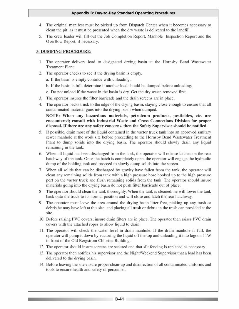
4. The original manifest must be picked up from Dispatch Center when it becomes necessary toclean the pit, as it must be presented when the dry waste is delivered to the landfill.
5. The crew leader will fill out the Job Completion Report, Manhole Inspection Report and theOverflow Report, if necessary.
3. DUMPING PROCEDURE:
1. The operator delivers load to designated drying basin at the Hornsby Bend WastewaterTreatment Plant.
2. The operator checks to see if the drying basin is empty.
a. If the basin is empty continue with unloading.
b. If the basin is full, determine if another load should be dumped before unloading.
c. Do not unload if the waste in the basin is dry. Get the dry waste removed first.
3. The operator insures the filter barricade and the drain screens are in place.
4. The operator backs truck to the edge of the drying basin, staying close enough to ensure that allcontaminated material goes into the drying basin when dumped.
NOTE: When any hazardous materials, petroleum products, pesticides, etc. areencountered; consult with Industrial Waste and Cross Connections Division for properdisposal. If there are any safety concerns, then the Safety Supervisor should be notified.
5. If possible, drain most of the liquid contained in the vactor truck tank into an approved sanitarysewer manhole at the work site before proceeding to the Hornsby Bend Wastewater TreatmentPlant to dump solids into the drying basin. The operator should slowly drain any liquidremaining in the tank.
6. When all liquid has been discharged from the tank, the operator will release latches on the rearhatchway of the tank. Once the hatch is completely open, the operator will engage the hydraulicdump of the holding tank and proceed to slowly dump solids into the screen.
7. When all solids that can be discharged by gravity have fallen from the tank, the operator willclean any remaining solids from tank with a high pressure hose hooked up to the high pressureport on the vactor truck and flush remaining solids from the tank. The operator should insurematerials going into the drying basin do not push filter barricade out of place.
8 The operator should clean the tank thoroughly. When the tank is cleaned, he will lower the tankback onto the truck to its normal position and will close and latch the rear hatchway.
9. The operator must leave the area around the drying basin litter free, picking up any trash ordebris he may have left at this site, and placing all trash or debris in the trash can provided at thesite.
10. Before raising PVC covers, insure drain filters are in place. The operator then raises PVC draincovers with the attached ropes to allow liquid to drain.
11. The operator will check the water level in drain manhole. If the drain manhole is full, theoperator will pump it down by vactoring the liquid off the top and unloading it into lagoon 11Win front of the Old Bergstrom Chlorine Building.
12. The operator should insure screens are secured and that silt fencing is replaced as necessary.
13. The operator then notifies his supervisor and the Night/Weekend Supervisor that a load has beendelivered to the drying basin.
14. Before leaving the site ensure proper clean-up and disinfection of all contaminated uniforms andtools to ensure health and safety of personnel.
Appendix B: Day-to-Day Standard Operating Procedures
B-41

4. CLEANING THE DRYING BASIN:
1. It is the responsibility of Public Service Manager to insure the drying basin is cleaned in a timelymanner.
2. The operator will perform a paint filter test to determine the moisture content of materials in thedrying basin.
3. The operator will remove the filter barricades to prevent damage.
4. The operator will use the backhoe to scrape the dry waste and load into a dump truck.
5. The operator will hose down and sweep the basin to move all solids to the bottom, taking carenot to wash solids into floor drain.
6. The operator will use the flat shovel to scrape the waste from around the floor drains and placethe waste in front of the filter barricades. This wet waste will be dried and hauled later.
7. The operator will spray or dispense 1/2 cup of deodorant.
8. The operator will deliver waste to the City of Austin Landfill, insuring that the original manifestis in his possession at delivery time.
9. The operator checks water level in drain manhole. If the drain manhole is full, he will pump itdown by vactoring the liquid off the top and unloading it into lagoon 11W in front of the OldBergstrom Chlorine Building.
10. Grit will be hauled to FM 812 Landfill.
11. Before leaving the site ensure proper clean-up and disinfection of all contaminated uniforms andtools to ensure health and safety of personnel.
Optimizing Operation, Maintenance, and Rehabilitation of Sanitary Sewer Collection Systems
B-42
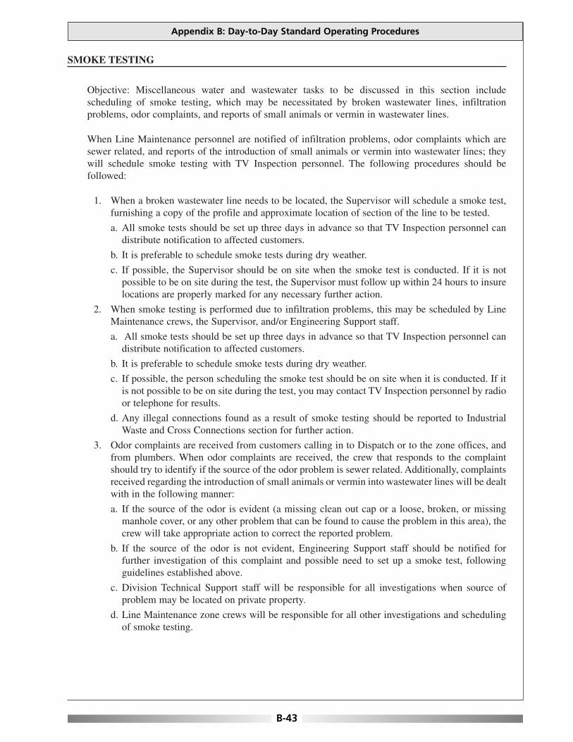
SMOKE TESTING
Objective: Miscellaneous water and wastewater tasks to be discussed in this section includescheduling of smoke testing, which may be necessitated by broken wastewater lines, infiltrationproblems, odor complaints, and reports of small animals or vermin in wastewater lines.
When Line Maintenance personnel are notified of infiltration problems, odor complaints which aresewer related, and reports of the introduction of small animals or vermin into wastewater lines; theywill schedule smoke testing with TV Inspection personnel. The following procedures should befollowed:
1. When a broken wastewater line needs to be located, the Supervisor will schedule a smoke test,furnishing a copy of the profile and approximate location of section of the line to be tested.
a. All smoke tests should be set up three days in advance so that TV Inspection personnel candistribute notification to affected customers.
b. It is preferable to schedule smoke tests during dry weather.
c. If possible, the Supervisor should be on site when the smoke test is conducted. If it is notpossible to be on site during the test, the Supervisor must follow up within 24 hours to insurelocations are properly marked for any necessary further action.
2. When smoke testing is performed due to infiltration problems, this may be scheduled by LineMaintenance crews, the Supervisor, and/or Engineering Support staff.
a. All smoke tests should be set up three days in advance so that TV Inspection personnel candistribute notification to affected customers.
b. It is preferable to schedule smoke tests during dry weather.
c. If possible, the person scheduling the smoke test should be on site when it is conducted. If itis not possible to be on site during the test, you may contact TV Inspection personnel by radioor telephone for results.
d. Any illegal connections found as a result of smoke testing should be reported to IndustrialWaste and Cross Connections section for further action.
3. Odor complaints are received from customers calling in to Dispatch or to the zone offices, andfrom plumbers. When odor complaints are received, the crew that responds to the complaintshould try to identify if the source of the odor problem is sewer related. Additionally, complaintsreceived regarding the introduction of small animals or vermin into wastewater lines will be dealtwith in the following manner:
a. If the source of the odor is evident (a missing clean out cap or a loose, broken, or missingmanhole cover, or any other problem that can be found to cause the problem in this area), thecrew will take appropriate action to correct the reported problem.
b. If the source of the odor is not evident, Engineering Support staff should be notified forfurther investigation of this complaint and possible need to set up a smoke test, followingguidelines established above.
c. Division Technical Support staff will be responsible for all investigations when source ofproblem may be located on private property.
d. Line Maintenance zone crews will be responsible for all other investigations and schedulingof smoke testing.
Appendix B: Day-to-Day Standard Operating Procedures
B-43

This page is intentionally blank.
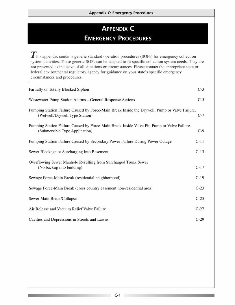
This appendix contains generic standard operation procedures (SOPs) for emergency collectionsystem activities. These generic SOPs can be adapted to fit specific collection system needs. They arenot presented as inclusive of all situations or circumstances. Please contact the appropriate state orfederal environmental regulatory agency for guidance on your state’s specific emergencycircumstances and procedures.
Appendix C: Emergency Procedures
C-1
APPENDIX CEMERGENCY PROCEDURES
Partially or Totally Blocked Siphon C-3
Wastewater Pump Station Alarms—General Response Actions C-5
Pumping Station Failure Caused by Force-Main Break Inside the Drywell, Pump or Valve Failure.(Wetwell/Drywell Type Station) C-7
Pumping Station Failure Caused by Force-Main Break Inside Valve Pit, Pump or Valve Failure.(Submersible Type Application) C-9
Pumping Station Failure Caused by Secondary Power Failure During Power Outage C-11
Sewer Blockage or Surcharging into Basement C-13
Overflowing Sewer Manhole Resulting from Surcharged Trunk Sewer (No backup into building) C-17
Sewage Force-Main Break (residential neighborhood) C-19
Sewage Force-Main Break (cross country easement non-residential area) C-23
Sewer Main Break/Collapse C-25
Air Release and Vacuum Relief Valve Failure C-27
Cavities and Depressions in Streets and Lawns C-29

This page is intentionally blank.

PROBLEM: Partially or Totally Blocked Siphon
EMERGENCY PROCEDURES:
• Dispatch sewer crew to failing siphon immediately.
• Immediately have jet-flushing vehicle brought to the site if a blockage is discovered.
• If the cause of a blockage is unknown use a single port cutting nozzle and attach the nozzle tothe jet-flushing machine.
• If sewage is discharging to the environment, follow instructions defined in Overflowing SewerManhole Resulting from Surcharged Trunk Sewer for containment and cleanup.
• Insert the proper size sandtrap in the downstream invert of the downstream manhole to trap thedebris causing the blockage.
• Start flushing the siphon between 1000 and 1500 psi against the flow, using the high velocity jet-flushing vehicle brought to the site if a blockage is discovered. Work the nozzle back and forthuntil minimal debris is observed in the down stream manhole.
• If the blockage is grease related, use a grease solvent in accordance with policy. Care should beobserved when working with chemicals. Refer to material safety data sheets (MSDS) prior touse.
• The crew leader should take appropriate still photographs and video footage; if possible, of theoutdoor area of the sewer over flow and impacted area to thoroughly document the nature andextent of the impacts.
• Make out a report indicating: the time of the call, description of the problem, how the repair wasmade, personnel present and equipment used.
• If sewage bypassed the collection system, file DEP Bypass Notification Log and Bypass ReportForm as required by NPDES Permit.
Appendix C: Emergency Procedures
C-3
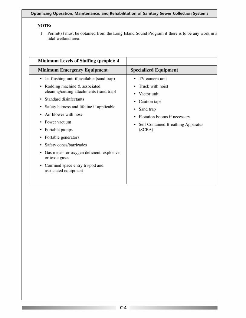
NOTE:
1. Permit(s) must be obtained from the Long Island Sound Program if there is to be any work in atidal wetland area.
Optimizing Operation, Maintenance, and Rehabilitation of Sanitary Sewer Collection Systems
C-4
• Jet flushing unit if available (sand trap)
• Rodding machine & associatedcleaning/cutting attachments (sand trap)
• Standard disinfectants
• Safety harness and lifeline if applicable
• Air blower with hose
• Power vacuum
• Portable pumps
• Portable generators
• Safety cones/barricades
• Gas meter-for oxygen deficient, explosiveor toxic gases
• Confined space entry tri-pod andassociated equipment
• TV camera unit
• Truck with hoist
• Vactor unit
• Caution tape
• Sand trap
• Flotation booms if necessary
• Self Contained Breathing Apparatus(SCBA)
Minimum Levels of Staffing (people): 4
Minimum Emergency Equipment Specialized Equipment
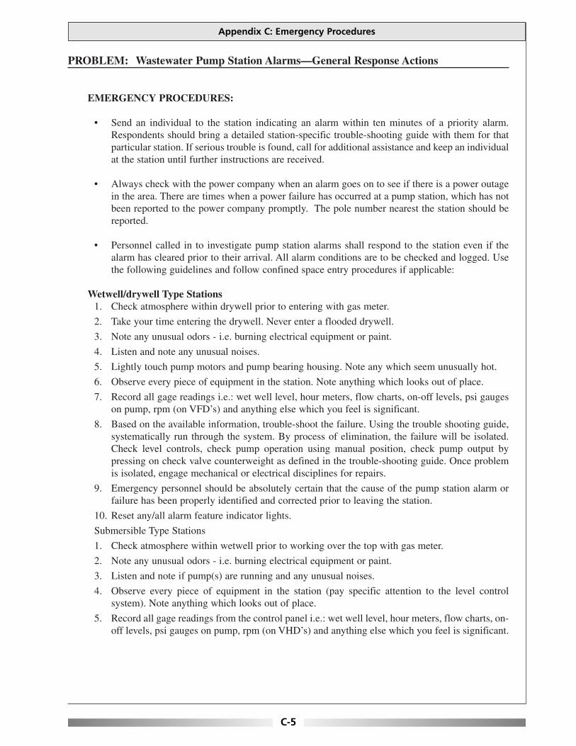
PROBLEM: Wastewater Pump Station Alarms—General Response Actions
EMERGENCY PROCEDURES:
• Send an individual to the station indicating an alarm within ten minutes of a priority alarm.Respondents should bring a detailed station-specific trouble-shooting guide with them for thatparticular station. If serious trouble is found, call for additional assistance and keep an individualat the station until further instructions are received.
• Always check with the power company when an alarm goes on to see if there is a power outagein the area. There are times when a power failure has occurred at a pump station, which has notbeen reported to the power company promptly. The pole number nearest the station should bereported.
• Personnel called in to investigate pump station alarms shall respond to the station even if thealarm has cleared prior to their arrival. All alarm conditions are to be checked and logged. Usethe following guidelines and follow confined space entry procedures if applicable:
Wetwell/drywell Type Stations1. Check atmosphere within drywell prior to entering with gas meter.
2. Take your time entering the drywell. Never enter a flooded drywell.
3. Note any unusual odors - i.e. burning electrical equipment or paint.
4. Listen and note any unusual noises.
5. Lightly touch pump motors and pump bearing housing. Note any which seem unusually hot.
6. Observe every piece of equipment in the station. Note anything which looks out of place.
7. Record all gage readings i.e.: wet well level, hour meters, flow charts, on-off levels, psi gaugeson pump, rpm (on VFD’s) and anything else which you feel is significant.
8. Based on the available information, trouble-shoot the failure. Using the trouble shooting guide,systematically run through the system. By process of elimination, the failure will be isolated.Check level controls, check pump operation using manual position, check pump output bypressing on check valve counterweight as defined in the trouble-shooting guide. Once problemis isolated, engage mechanical or electrical disciplines for repairs.
9. Emergency personnel should be absolutely certain that the cause of the pump station alarm orfailure has been properly identified and corrected prior to leaving the station.
10. Reset any/all alarm feature indicator lights.
Submersible Type Stations
1. Check atmosphere within wetwell prior to working over the top with gas meter.
2. Note any unusual odors - i.e. burning electrical equipment or paint.
3. Listen and note if pump(s) are running and any unusual noises.
4. Observe every piece of equipment in the station (pay specific attention to the level controlsystem). Note anything which looks out of place.
5. Record all gage readings from the control panel i.e.: wet well level, hour meters, flow charts, on-off levels, psi gauges on pump, rpm (on VHD’s) and anything else which you feel is significant.
Appendix C: Emergency Procedures
C-5

6. Based on the available information, trouble-shoot the failure. Using the trouble-shooting guide,systematically run through the system. By process of elimination, the failure will be isolated.Check level controls, check pump operation using manual position, check pump output byobserving the check valve counterweight as defined in the trouble shooting guide. Once problemis isolated, engage mechanical or electrical disciplines for repairs
7. Emergency personnel should be absolutely certain that the cause of the pump station alarm orfailure has been properly identified and corrected prior to leaving the station.
8. Reset any/all alarm feature indicator lights.
• Various types of level sensors may be present in the pump station, including bubbler systems,float switches, transducers, or rod-type probes. Similarly various types of controls may bepresent for pump cycling including pneumatic systems, simple relays and/or computerizedprocessors. The responding crew should be fully capable and trained in the proper function ofeach of these systems present within the municipality. Trouble shooting these controls is specificto the unit. Consequently, the O&M manual for the level sensor system and pump controlsshould be consulted during a failure.
• Pumps may be checked easily for operation by checking the arm of the check-valve in thedischarge line of an operating pump. If it feels "spongy" (or soft) when downward pressure isapplied with the palm of the hand, the pump is pumping. If a breaker is off and the pump motoris hot to the touch, DO NOT attempt to reset and start. If a pump motor is simply warm, oneattempt to restart can be made. Turing the selector switch to manual will normally start a pump,and the check valve arm should move upwards. If the pump has lost prime or is lugged, the checkvalve will not open.
Optimizing Operation, Maintenance, and Rehabilitation of Sanitary Sewer Collection Systems
C-6
• Gas meter-for oxygen deficient, explosiveor toxic gases
• Self Contained Breathing Apparatus(SCBA)
• Harness and lifeline
• Personnel protection equipment
• As applicable for trouble-shooting
Minimum Levels of Staffing (people): 2
Minimum Emergency Equipment Specialized Equipment

PROBLEM: Pumping Station Failure Caused by Force-Main Break Inside the Drywell,Pump or Valve Failure. (Wetwell/Drywell Type Station)
EMERGENCY PROCEDURES:
• Dispatch pumping station crew to the pumping station immediately.
• Upon arrival the crew should identity if the drywell and wetwell are flooded. The pumps may bestill pumping if the motor is located at floor level and the pumps are on the lower level or ifdrypit submersibles were installed.
• After further investigation, the crew should determine the nature of the failure, i.e. pump(s),valve(s) or force main(s) if possible prior to entering the drywell.
• Call additional crew to bring appropriate portable pump(s) including all required lengths ofsuction and discharge house, to the pumping station.
• Before entering the drywell, measure the atmospheric conditions for sufficient oxygen and thepresence of explosive or toxic gases. Remove all hazards as appropriate prior to entering station(including electrical and engulfment hazards).
• Constantly monitor the atmospheric conditions while working in the drywell of the station.
• Upon arrival of the portable pump, connect the appropriate lengths of suction hose that willsuspend well into the wetwell, and then connect enough discharge hose to pump into bypassconnection.
• Lock out and tag out (LOTO) the main line, disconnect (if applicable).
• Set up an additional portable trash pump to pump out the drywell into the wetwell.
• Enter drywell and inspect the following facilities:LightingVentilationSump pump operationMotor control system including air compressorsAuxiliary power systems and controlsBubbler system (if applicable)Pump alternator or processorControl and instrument readingsMCC failure indicatorsTemperature of pump motorsAll internal piping
• Isolate the failed component by valve operation. Start the auxiliary pump and motor, if possible(after exiting the drywell). Shut down bypass operation if possible.
• Complete repairs to pipe, pump or valve as per policy. If permanent materials are not readilyavailable, install blind flanges for temporary conditions. If auxiliary systems associated with thepermanent station are in operation, LOTO prior to installing repaired components.
Appendix C: Emergency Procedures
C-7

• Restore facilities to normal and inspect other components of the force main and pumping systemfor signs of similar failure.
• Shut down bypass operation. Do not disconnect hoses until repair is checked for leaks. Operatepumps to check repair under pressure and normal operating conditions.
• If no leaks are observed, return pumps to normal conditions by removing LOTO. Monitor pumpsto check lead/lag operations.
• Proceed to wetwell for inspection. Before entering the wetwell, measure the atmosphericconditions for sufficient oxygen and the presence of explosive or toxic gases. Check thefollowing as facilities applicable:
LightingVentilationWetwell levelBar rack and/or comminutor (if applicable)Float controls/level sensorsGrease assessment
• Make out a report indicating; the time of the call, description of the problem, how the repair wasmade, personnel present and equipment used.
• If sewage bypassed the collection system, file DEP Bypass Notification Log and Bypass ReportForm as required by NPDES Permit.
Optimizing Operation, Maintenance, and Rehabilitation of Sanitary Sewer Collection Systems
C-8
• Harness and lifeline
• Flash light
• Emergency lighting
• Portable pumps and hoses
• Miscellaneous tools
• Personal protection equipment
• Gas meter-for oxygen deficient, explosiveor toxic gases
• Self Contained Breathing Apparatus(SCBA)
Minimum Levels of Staffing (people): 2–4
Minimum Emergency Equipment Specialized Equipment

PROBLEM: Pumping Station Failure Caused by Force-Main Break Inside Valve Pit,Pump or Valve Failure. (Submersible Type Application)
EMERGENCY PROCEDURES:
• Dispatch pumping station crew to the pumping station immediately.
• Upon arrival the crew should identity the storage capacity in the wetwell. This will give someindication of the time available for response.
• Inspect the motor control circuit looking for failure indications. Check processor to determinefailure if applicable. If pump failure is determined, skip to wetwell inspection steps.
• Inspect the valvepit. Observe all valves and force mains. If flooded, arrange to pump out thevalve pit. If failure within the valvepit is detected, skip to bypass steps.
• Prior to viewing the wetwell, measure the atmospheric conditions for sufficient oxygen and thepresence of explosive or toxic gases. If flooded, skip to bypass steps.
• Constantly monitor the atmospheric conditions while working in or above the wetwell. Inspectthe wetwell. Check the wetwell floats or level control system, bar rack and pump volute are forclogging or other problems.
Bypass Steps
• If pump failure, determine if bypass pumping is necessary. If unnecessary skip to repairprocedures.
• Bypass pump. Call additional crew to bring appropriate portable pump(s) including all requiredlengths of suction and discharge house, to the pumping station if necessary. Upon arrival of theportable pump, connect the appropriate lengths of suction hose that will suspend well into thewetwelll, and then connect enough discharge hose to pump into appropriate manhole or bypassconnection (if so equipped). Go through the procedures for starting the portable pump, and beginpumping.
Repair Steps
• Lock out and tag out (LOTO) the main line, disconnect (if applicable).
• If pump station valve pit is flooded, pump out the valve pit with portable trash pump as necessaryto effect repairs.
• Enter valve pit or wet well and inspect the piping and valves for cause of failure. (Monitor theatmospheric conditions for sufficient oxygen and the presence of explosive or toxic gases).
• Complete repairs to pipe, pump or valve as per policy. If permanent materials are not readilyavailable, install temporary repairs until the permanent repairs can be completed.
• Restore facilities to normal and inspect other components of the force main and pumping systemfor signs of similar failure.
Appendix C: Emergency Procedures
C-9
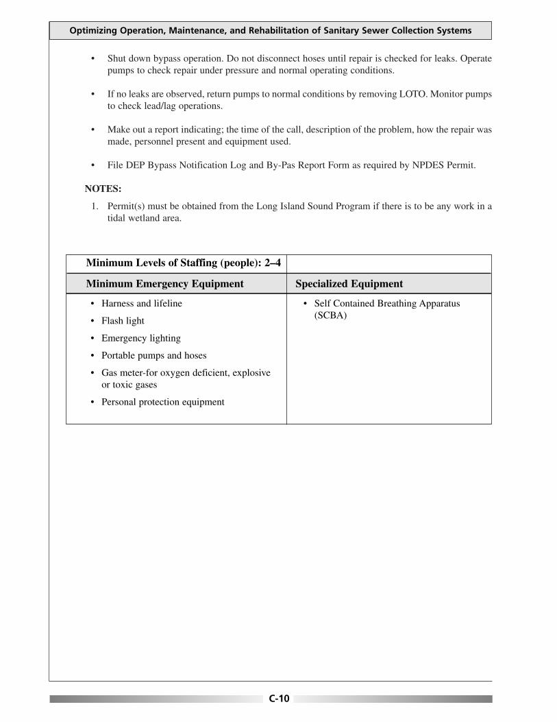
• Shut down bypass operation. Do not disconnect hoses until repair is checked for leaks. Operatepumps to check repair under pressure and normal operating conditions.
• If no leaks are observed, return pumps to normal conditions by removing LOTO. Monitor pumpsto check lead/lag operations.
• Make out a report indicating; the time of the call, description of the problem, how the repair wasmade, personnel present and equipment used.
• File DEP Bypass Notification Log and By-Pas Report Form as required by NPDES Permit.
NOTES:
1. Permit(s) must be obtained from the Long Island Sound Program if there is to be any work in atidal wetland area.
Optimizing Operation, Maintenance, and Rehabilitation of Sanitary Sewer Collection Systems
C-10
• Harness and lifeline
• Flash light
• Emergency lighting
• Portable pumps and hoses
• Gas meter-for oxygen deficient, explosiveor toxic gases
• Personal protection equipment
• Self Contained Breathing Apparatus(SCBA)
Minimum Levels of Staffing (people): 2–4
Minimum Emergency Equipment Specialized Equipment

PROBLEM: Pumping Station Failure Caused by Secondary Power Failure During Power Outage
EMERGENCY PROCEDURES:
• Dispatch pumping station crew to the pumping station immediately. The crew needs to bring theauxiliary generator for that specific station as a backup assuming that repair to the dedicatedgenerator is untimely.
• Dispatcher shall request the assistance of the power company in restoring power to the station ifnecessary. Determine the estimated time of arrival of the power company crew and then notifythe pumping station operators.
• Pumping station operators should check the overhead power lines for fuses that might haveblown or down power lines as they approach the pumping station. If the operators notice a blownfuse or down power line, identify the pole number(s), and notify the dispatcher to relay to thepower company the location and the pole number(s).
• Lock out and tag out (LOTO) the main line, disconnect (if applicable).
• Check all components of dedicated generator to determine failure cause. Utilize manufacturerprepared trouble-shooting guide to aid in diagnosis. If unrepairable immediately, connect theportable generator to the auxiliary power connection located outside the building. Examine plugtype and ensure consistency. Use adapters as necessary.
• Go through the specific procedures for starting the generator to supply power to the station.
• Obtain the services of a qualified generator repair facility to address the dedicated generatorfailure.
• Once fully repaired, disconnect the portable generator and reconnect the dedicated unit. Operatethe dedicated unit through several pump cycles. Check unit for regular exercise.
Appendix C: Emergency Procedures
C-11
• Harness and lifeline
• Flash light
• Emergency lighting
• Portable generator
• Personal protection equipment
• Gas meter-for oxygen deficient, explosiveor toxic gases
• Power testing equipment
Minimum Levels of Staffing (people): 2–3
Minimum Emergency Equipment Specialized Equipment

This page is intentionally blank.

PROBLEM: Sewer Blockage or Surcharging into Basement
EMERGENCY PROCEDURES:
• Dispatch the sewer crew to the complainant address immediately.
• If the flow is questionable (not reasonable for the given service area) go to the upstream manholeto visually compare flows.
• If the flow from both manholes is reasonable for the area, notify the property owners that theproblem is in their service lateral and to contact a plumber or sewer service contractor to relievethe blockage.
• Refer to sewer maps for location of sewers (private lands, flow patterns, manholes, etc.) anddetermine if the area is served by a pump station, before responding to the call.
• If the area of complaint is served by a pump station, check to see if any alarms from the pumpstation have been received at the WPCF.
• Notify the property owner you are on the site, upon arrival.
• Check flow in downstream manhole from the complaint location.
• Install the proper size sandtrap in the downstream invert of the manhole before clearing theblockage to capture the debris. From the debris collected try to determine the cause of theblockage and remove the debris from the manhole.
• Use the necessary equipment to relieve the blockage, either by jet flushing or power rodding.
• If the downstream manhole is flowing full, continue checking manholes downstream until a drymanhole is found. Clear blockage upstream from the dry manhole.
• Notify supervisor and describe the bypass. The supervisor will notify the proper authorities andagencies: (See notification charts)
• If the blockage is in city/town main line, relieve the blockage, clean up the property owner’sbasement as per policy and spray an industry standard disinfectant. If blockage is determined tobe in property owner’s lateral connection, direct property owner to his/her responsibility to clear.
• Make out a report indicating; the time of the call, description of the problem, how the repair wasmade, personnel present and equipment used.
• If sewage bypassed the collection system, file DEP Bypass Notification Log and Bypass ReportForm as required by NPDES Permit.
Appendix C: Emergency Procedures
C-13
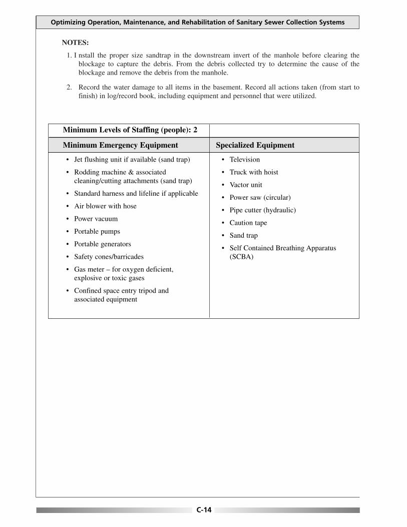
NOTES:
1. I nstall the proper size sandtrap in the downstream invert of the manhole before clearing theblockage to capture the debris. From the debris collected try to determine the cause of theblockage and remove the debris from the manhole.
2. Record the water damage to all items in the basement. Record all actions taken (from start tofinish) in log/record book, including equipment and personnel that were utilized.
Optimizing Operation, Maintenance, and Rehabilitation of Sanitary Sewer Collection Systems
C-14
• Jet flushing unit if available (sand trap)
• Rodding machine & associatedcleaning/cutting attachments (sand trap)
• Standard harness and lifeline if applicable
• Air blower with hose
• Power vacuum
• Portable pumps
• Portable generators
• Safety cones/barricades
• Gas meter – for oxygen deficient,explosive or toxic gases
• Confined space entry tripod andassociated equipment
• Television
• Truck with hoist
• Vactor unit
• Power saw (circular)
• Pipe cutter (hydraulic)
• Caution tape
• Sand trap
• Self Contained Breathing Apparatus(SCBA)
Minimum Levels of Staffing (people): 2
Minimum Emergency Equipment Specialized Equipment

STEPS TO BE TAKEN BY PROPERTY OWNERS WHEN SEWAGE BACK-UP OCCURES
Call and report stoppage. Use phone numbers listed for WPCF at night. The WPCF will check themain sewer for blockage. If the main sewer is blocked the WPCF will clear it. If the main sewer isclear then the property owner must hire a licensed plumber, drain layer, or sewer cleaner to freeany blockage, which might exist in their lateral. The property owner is responsible to pay for thisactivity.
NOTE: PROPER RODDING PROCEDURE GUIDELINE
In cases where a property owner needs to free a blockage within their lateral, the following proceduresshall be implemented. The plumber shall use a 4" cutter at the end of the rod. If the plumber relievesthe blockage, he shall then rod the house connection to the main sewer line.
If the blockage is found in the portion of the sewer house connection located within private property,the owner must hire a licensed contractor to perform the necessary repair work, under permit andinspection from the local WPCF.
All repair work on the sewer house connection must be performed under permit issued by the WPCFto a licensed contractor, and will be inspected by the local WPCF personnel.
RODDINGS:
If the property owner, licensed plumber, drain layer on sewer cleaner does not call the WPCF andrequest the main sewer check prior to rodding. The WPCF will not assume liability if the problem islocated in he main sewer.
If there is a blockage, but no record of the house connection, the owner must prove where the blockageis located. This can be done by excavation or electronic locator in he presence of an inspector.
The WPCF requires proper rodding procedures. The rodder must use a 4" cutter. If he can’t breakthrough the blockage, he will then start using smaller cutters back up to 4". He will then push theblockage into the main sewer.
Appendix C: Emergency Procedures
C-15

This page is intentionally blank.
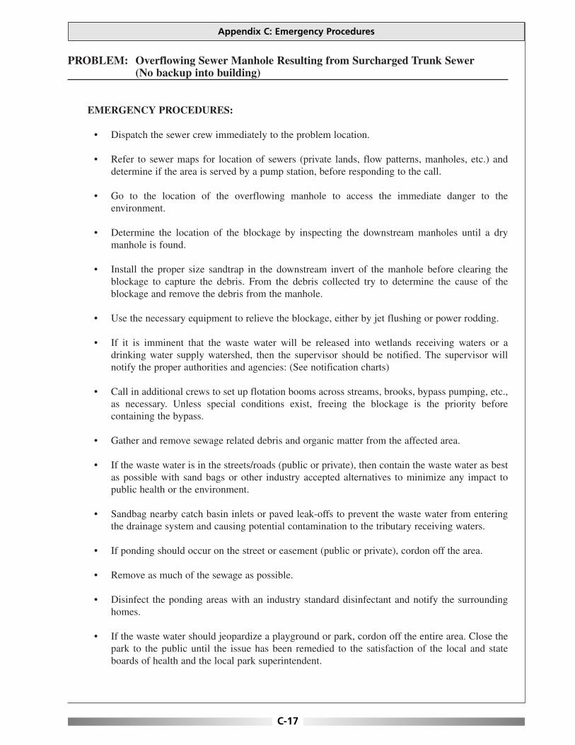
PROBLEM: Overflowing Sewer Manhole Resulting from Surcharged Trunk Sewer (No backup into building)
EMERGENCY PROCEDURES:
• Dispatch the sewer crew immediately to the problem location.
• Refer to sewer maps for location of sewers (private lands, flow patterns, manholes, etc.) anddetermine if the area is served by a pump station, before responding to the call.
• Go to the location of the overflowing manhole to access the immediate danger to theenvironment.
• Determine the location of the blockage by inspecting the downstream manholes until a drymanhole is found.
• Install the proper size sandtrap in the downstream invert of the manhole before clearing theblockage to capture the debris. From the debris collected try to determine the cause of theblockage and remove the debris from the manhole.
• Use the necessary equipment to relieve the blockage, either by jet flushing or power rodding.
• If it is imminent that the waste water will be released into wetlands receiving waters or adrinking water supply watershed, then the supervisor should be notified. The supervisor willnotify the proper authorities and agencies: (See notification charts)
• Call in additional crews to set up flotation booms across streams, brooks, bypass pumping, etc.,as necessary. Unless special conditions exist, freeing the blockage is the priority beforecontaining the bypass.
• Gather and remove sewage related debris and organic matter from the affected area.
• If the waste water is in the streets/roads (public or private), then contain the waste water as bestas possible with sand bags or other industry accepted alternatives to minimize any impact topublic health or the environment.
• Sandbag nearby catch basin inlets or paved leak-offs to prevent the waste water from enteringthe drainage system and causing potential contamination to the tributary receiving waters.
• If ponding should occur on the street or easement (public or private), cordon off the area.
• Remove as much of the sewage as possible.
• Disinfect the ponding areas with an industry standard disinfectant and notify the surroundinghomes.
• If the waste water should jeopardize a playground or park, cordon off the entire area. Close thepark to the public until the issue has been remedied to the satisfaction of the local and stateboards of health and the local park superintendent.
Appendix C: Emergency Procedures
C-17

Optimizing Operation, Maintenance, and Rehabilitation of Sanitary Sewer Collection Systems
C-18
• Make out a report indicating; the time of the call, description of the problem, how the repair wasmade, personnel present and equipment used.
• If sewage bypassed the collection system, file DEP Bypass Notification Log and Bypass ReportForm as required by NPDES Permit.
NOTE:
1. Permit(s) must be obtained from the Long Island Sound Program if there is to be any work in atidal wetland area.
• Jet flushing unit if available (sand trap)
• Rodding machine & associatedcleaning/cutting attachments (sand trap)
• Standard disinfectants
• Safety harness and lifeline if applicable
• Air blower with hose
• Power vacuum
• Portable pumps
• Portable generators
• Safety cones/barricades
• Gas meter-for oxygen deficient, explosiveor toxic gases
• Confined space entry tri-pod andassociated equipment
• TV camera unit
• Truck with hoist
• Vactor unit
• Power saw (circular)
• Pipe cutter (hydraulic)
• Caution tape
• Sand trap
• Flotation booms if necessary
• Self Contained Breathing Apparatus(SCBA)
Minimum Levels of Staffing (people): 2-3
Minimum Emergency Equipment Specialized Equipment
PROBLEM: Sewage Force-Main Break (residential neighborhood)
EMERGENCY PROCEDURES:
• Dispatch a sewer crew to the site to assess the immediate danger to the environment and todetermine who and what might be affected.
• Refer to the sewer maps for location of sewers (private lands flow patterns, manholes, etc.) anddetermine if the area is served by a pump station, before responding to the call.
• Request additional manpower and equipment as needed based on initial damage assessment (e.g.excavating crew, bypass pumping equipment, etc.).
• Bypass pumping from the pump station wetwell to the force main discharge manhole may berequired. If necessary, set up bypass pumping equipment.
• Call in additional crews to set up flotation booms across streams, brooks, sandbagging, etc., asnecessary. Unless special conditions exist, bypassing the broken force main is a priority beforecontaining the bypass.
• Gather and remove sewage related debris and organic matter from the affected area.
• If the waste water is in the streets/roads (public or private), then contain the waste water as bestas possible with sand bags or other industry accepted alternatives to minimize any impact topublic health or the environment.
• Sandbag nearby catch basin inlets or paved leak-offs to prevent the waste water from enteringthe drainage system and causing potential contamination to the tributary receiving waters.
• If ponding should occur on the street or easement (public or private), cordon off the area.
• Remove as much of the sewage as possible.
• Disinfect the ponding areas with an industry standard disinfectant and notify the surroundinghomes.
• If the waste water should jeopardize a playground or park, cordon off the entire area. Close thepark to the public until the issue has been remedied to the satisfaction of the local and stateboards of health and the local park superintendent.
• After the bypass pumping equipment is at the site and in place, lock-out and tag-out (LOTO) thepumps in the pumping station.
• Draw down the wetwell as much as possible and maintain low level.
• Drain the force-main by first closing down the gate valve on the upstream side of the dischargecheck valve in the pumping station.
• Open the check valve by hand and secure it in place.
Appendix C: Emergency Procedures
C-19

• Slowly bleed the force-main back into the wetwell by slowly opening the gate valve on thedischarge side of the pump, but only to the point where the force-main stops leaking and thereis enough room to make the repair. Constant communication must take place between the crewlocated at the break and the crew located at the pump station.
• Close the gate valve and return the check valve to its normal operating position and then fullyopen the gate valve.
• Repair force main break as per policy.
• After the repair is complete, remove LOTO and return the pumps to normal operating position.
• Run the pump in the hand manual position to fill the force-main. Once completed, observeseveral pumping cycles before completely back-filling the excavation.
• Upon confirmation of adequacy of the repair, backfill the excavation (if necessary) and restoresurface conditions to match existing conditions.
• While the crew is restoring the excavation, the crew leader should conduct a preliminaryassessment of damage to private and public property. The crew leader should take appropriatestill photographs and video footage; if possible, of the outdoor area of the sewer over flow andimpacted area to thoroughly document the nature and extent of the impacts.
• Make out a report indicating,; the time of the call, description of the problem, how the repair wasmade, personnel present and equipment used.
• If sewage bypassed the collection system, file DEP Bypass Notification Log and Bypass ReportForm as required by NPDES Permit.
NOTE:
1. Permit(s) must be obtained from the Long Island Sound Program if there is to be any work in atidal wetland area.
Optimizing Operation, Maintenance, and Rehabilitation of Sanitary Sewer Collection Systems
C-20
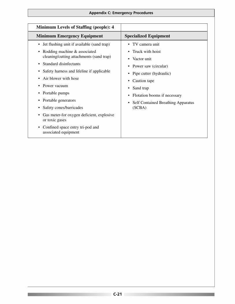
Appendix C: Emergency Procedures
C-21
• Jet flushing unit if available (sand trap)
• Rodding machine & associatedcleaning/cutting attachments (sand trap)
• Standard disinfectants
• Safety harness and lifeline if applicable
• Air blower with hose
• Power vacuum
• Portable pumps
• Portable generators
• Safety cones/barricades
• Gas meter-for oxygen deficient, explosiveor toxic gases
• Confined space entry tri-pod andassociated equipment
• TV camera unit
• Truck with hoist
• Vactor unit
• Power saw (circular)
• Pipe cutter (hydraulic)
• Caution tape
• Sand trap
• Flotation booms if necessary
• Self Contained Breathing Apparatus(SCBA)
Minimum Levels of Staffing (people): 4
Minimum Emergency Equipment Specialized Equipment

This page is intentionally blank.

PROBLEM: Sewage Force-Main Break (cross country easement non-residential area)
EMERGENCY PROCEDURES:
• Dispatch a sewer crew to the site to assess the immediate danger to the environment and todetermine who and what might be affected.
• Refer to the sewer maps for location of sewers (private lands flow patterns, manholes, etc.) anddetermine if the area is served by a pump station, before responding to the call.
• Request additional manpower and equipment as needed based on initial damage assessment (e.g.excavating crew, bypass pumping equipment, etc.)
• Bypass pumping from the pump station wetwell to the force main discharge manhole may berequired. If necessary, set up bypass pumping equipment.
• If bypass pumping is not an option, then the line may need to be repaired under pressure. Shutdown the pumping station only if detention time is known and can be mitigated.
• Call in additional crews to set up flotation booms across streams, brooks, sandbagging, etc., asnecessary. Unless special conditions exist, bypassing the broken force main is a priority beforecontaining the bypass.
• The crew shall initiate measures to contain the sewer overflow as best as possible, cordon off theaffected area and place absorbing booms or sand bags to collect any floatable debris.
• Check the tributary area to determine if the discharge will affect any receiving waters.
• If it is determined that the receiving water may be affected, and then the dispatcher should notifythe proper authorities or agency.
• If the break is on the pipe length, then a repair can be made with a wrap-around sleeve. If thebreak is at the bell, then a bell-joint clamp may be used.
• If a repair cannot be made while the line is under pressure or bypass pumping cannot becompleted, then only two (2) alternatives exist:
1. Utilize a vactor tuck to remove the water from the wetwell. Discharge the water into amanhole in a different tributary area or at the treatment plant.
2. If the vactor truck has insufficient volume, the scenario may require the assistance of severaltanker trucks or the use of a fractionalization tank to perform this function.
• Refer to the force-main break in residential neighborhood and follow the procedure for drainingthe force-main and returning the pumping station to normal operating procedures.
• Upon confirmation of adequacy of the repair, backfill the excavation (if necessary) and restoresurface conditions to match existing conditions.
Appendix C: Emergency Procedures
C-23
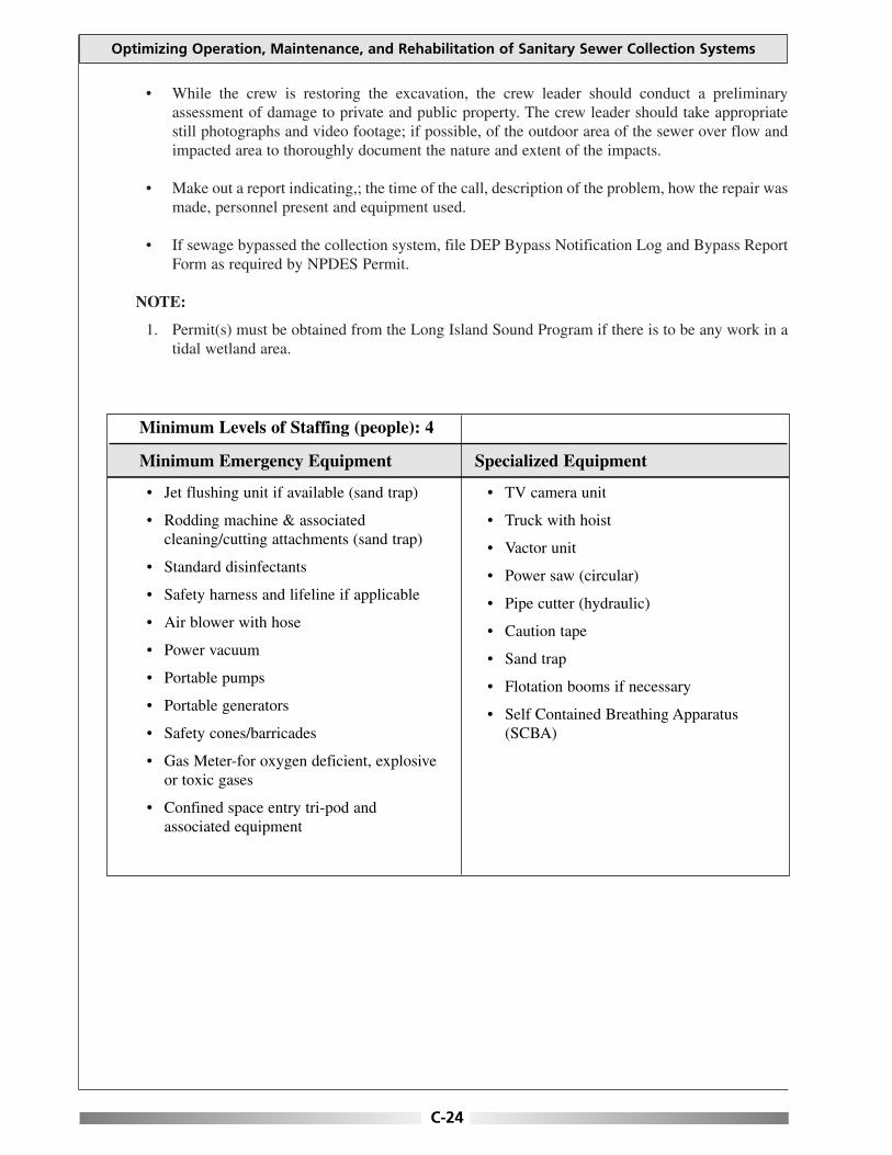
• While the crew is restoring the excavation, the crew leader should conduct a preliminaryassessment of damage to private and public property. The crew leader should take appropriatestill photographs and video footage; if possible, of the outdoor area of the sewer over flow andimpacted area to thoroughly document the nature and extent of the impacts.
• Make out a report indicating,; the time of the call, description of the problem, how the repair wasmade, personnel present and equipment used.
• If sewage bypassed the collection system, file DEP Bypass Notification Log and Bypass ReportForm as required by NPDES Permit.
NOTE:
1. Permit(s) must be obtained from the Long Island Sound Program if there is to be any work in atidal wetland area.
Optimizing Operation, Maintenance, and Rehabilitation of Sanitary Sewer Collection Systems
C-24
• Jet flushing unit if available (sand trap)
• Rodding machine & associatedcleaning/cutting attachments (sand trap)
• Standard disinfectants
• Safety harness and lifeline if applicable
• Air blower with hose
• Power vacuum
• Portable pumps
• Portable generators
• Safety cones/barricades
• Gas Meter-for oxygen deficient, explosiveor toxic gases
• Confined space entry tri-pod andassociated equipment
• TV camera unit
• Truck with hoist
• Vactor unit
• Power saw (circular)
• Pipe cutter (hydraulic)
• Caution tape
• Sand trap
• Flotation booms if necessary
• Self Contained Breathing Apparatus(SCBA)
Minimum Levels of Staffing (people): 4
Minimum Emergency Equipment Specialized Equipment

PROBLEM: Sewer Main Break/Collapse
EMERGENCY PROCEDURES:
• Dispatch sewer crew to location of break/collapse immediately.
• Set up signs, barricades, and/or barrels for traffic control and public safety.
• Reroute traffic as necessary. Deploy traffic control measures such as, police or flag person asneeded.
• Request additional manpower and equipment as needed based on initial damage assessment (e.g.excavating crew, bypass pumping equipment, etc.).
• Bypass pumping from the upstream manhole to the downstream manhole may be required. Ifnecessary, set up bypass pumping equipment. If not necessary, prepare for repairs while the pipeis flowing.
• Call in additional crews to set up flotation booms across streams, brooks, sandbagging, etc., asnecessary. Unless special conditions exist, bypassing the failed sewer main is a priority beforecontaining the bypass.
• Gather and remove sewage related debris and organic matter from the affected area.
• If the waste water is in the streets/roads (public or private), then contain the waste water as bestas possible with sand bags or other industry accepted alternatives to minimize any impact topublic health or the environment.
• Sandbag nearby catch basin inlets or paved leak-offs to prevent the waste water from enteringthe drainage system and causing potential contamination to the tributary receiving waters.
• If ponding should occur on the street or easement (public or private), cordon off the area.
• Remove as much of the sewage as possible.
• Disinfect the ponding areas with an industry standard disinfectant and notify the surroundinghomes.
• If the waste water should jeopardize a playground or park, cordon off the entire area. Close thepark to the public until the issue has been remedied to the satisfaction of the local and stateboards of health and the local park superintendent.
• Determine the location of the break/collapse and make any necessary repairs. Use repairprocedures consistent with policy. If the break is on the pipe length, then a repair can be madewith a wrap-around sleeve. If the break is at the bell, then a bell-joint clamp may be used.
• Upon confirmation of adequacy of the repair, backfill the excavation (if necessary) and restoresurface conditions to match existing conditions.
Appendix C: Emergency Procedures
C-25
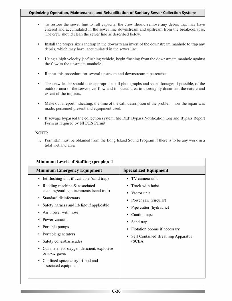
• To restore the sewer line to full capacity, the crew should remove any debris that may haveentered and accumulated in the sewer line downstream and upstream from the break/collapse.The crew should clean the sewer line as described below.
• Install the proper size sandtrap in the downstream invert of the downstream manhole to trap anydebris, which may have, accumulated in the sewer line.
• Using a high velocity jet-flushing vehicle, begin flushing from the downstream manhole againstthe flow to the upstream manhole.
• Repeat this procedure for several upstream and downstream pipe reaches.
• The crew leader should take appropriate still photographs and video footage; if possible, of theoutdoor area of the sewer over flow and impacted area to thoroughly document the nature andextent of the impacts.
• Make out a report indicating; the time of the call, description of the problem, how the repair wasmade, personnel present and equipment used.
• If sewage bypassed the collection system, file DEP Bypass Notification Log and Bypass ReportForm as required by NPDES Permit.
NOTE:
1. Permit(s) must be obtained from the Long Island Sound Program if there is to be any work in atidal wetland area.
Optimizing Operation, Maintenance, and Rehabilitation of Sanitary Sewer Collection Systems
C-26
• Jet flushing unit if available (sand trap)
• Rodding machine & associatedcleaning/cutting attachments (sand trap)
• Standard disinfectants
• Safety harness and lifeline if applicable
• Air blower with hose
• Power vacuum
• Portable pumps
• Portable generators
• Safety cones/barricades
• Gas meter-for oxygen deficient, explosiveor toxic gases
• Confined space entry tri-pod andassociated equipment
• TV camera unit
• Truck with hoist
• Vactor unit
• Power saw (circular)
• Pipe cutter (hydraulic)
• Caution tape
• Sand trap
• Flotation booms if necessary
• Self Contained Breathing Apparatus(SCBA
Minimum Levels of Staffing (people): 4
Minimum Emergency Equipment Specialized Equipment
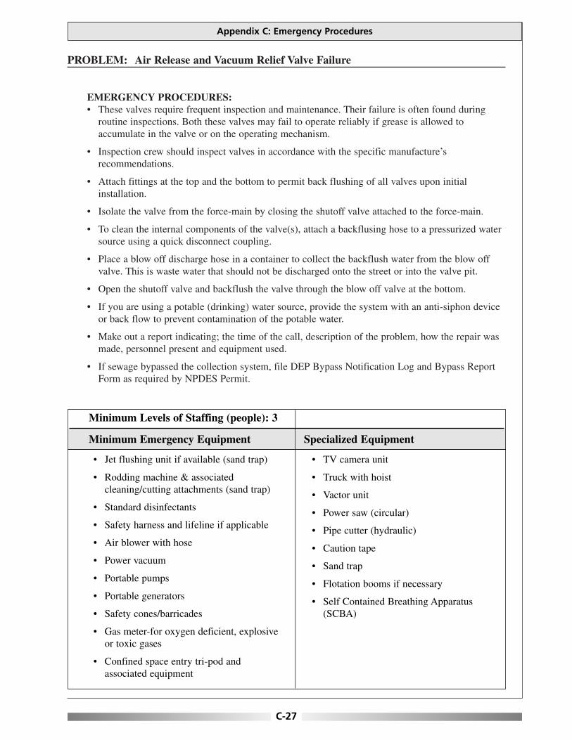
PROBLEM: Air Release and Vacuum Relief Valve Failure
EMERGENCY PROCEDURES:• These valves require frequent inspection and maintenance. Their failure is often found during
routine inspections. Both these valves may fail to operate reliably if grease is allowed toaccumulate in the valve or on the operating mechanism.
• Inspection crew should inspect valves in accordance with the specific manufacture’srecommendations.
• Attach fittings at the top and the bottom to permit back flushing of all valves upon initialinstallation.
• Isolate the valve from the force-main by closing the shutoff valve attached to the force-main.
• To clean the internal components of the valve(s), attach a backflusing hose to a pressurized watersource using a quick disconnect coupling.
• Place a blow off discharge hose in a container to collect the backflush water from the blow offvalve. This is waste water that should not be discharged onto the street or into the valve pit.
• Open the shutoff valve and backflush the valve through the blow off valve at the bottom.
• If you are using a potable (drinking) water source, provide the system with an anti-siphon deviceor back flow to prevent contamination of the potable water.
• Make out a report indicating; the time of the call, description of the problem, how the repair wasmade, personnel present and equipment used.
• If sewage bypassed the collection system, file DEP Bypass Notification Log and Bypass ReportForm as required by NPDES Permit.
Appendix C: Emergency Procedures
C-27
• Jet flushing unit if available (sand trap)
• Rodding machine & associatedcleaning/cutting attachments (sand trap)
• Standard disinfectants
• Safety harness and lifeline if applicable
• Air blower with hose
• Power vacuum
• Portable pumps
• Portable generators
• Safety cones/barricades
• Gas meter-for oxygen deficient, explosiveor toxic gases
• Confined space entry tri-pod andassociated equipment
• TV camera unit
• Truck with hoist
• Vactor unit
• Power saw (circular)
• Pipe cutter (hydraulic)
• Caution tape
• Sand trap
• Flotation booms if necessary
• Self Contained Breathing Apparatus(SCBA)
Minimum Levels of Staffing (people): 3
Minimum Emergency Equipment Specialized Equipment

This page is intentionally blank.
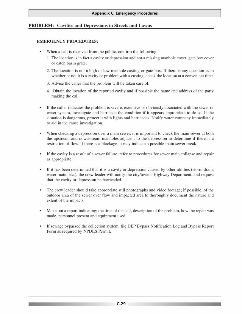
PROBLEM: Cavities and Depressions in Streets and Lawns
EMERGENCY PROCEDURES:
• When a call is received from the public, confirm the following:
1. The location is in fact a cavity or depression and not a missing manhole cover, gate box coveror catch basin grate.
2. The location is not a high or low manhole casting or gate box. If there is any question as towhether or not it is a cavity or problem with a casting, check the location at a convenient time.
3. Advise the caller that the problem will be taken care of.
4. Obtain the location of the reported cavity and if possible the name and address of the partymaking the call.
• If the caller indicates the problem is severe, extensive or obviously associated with the sewer orwater system, investigate and barricade the condition if it appears appropriate to do so. If thesituation is dangerous, protect it with lights and barricades. Notify water company immediatelyto aid in the cause investigation.
• When checking a depression over a main sewer, it is important to check the main sewer at boththe upstream and downstream manholes adjacent to the depression to determine if there is arestriction of flow. If there is a blockage, it may indicate a possible main sewer break.
• If the cavity is a result of a sewer failure, refer to procedures for sewer main collapse and repairas appropriate.
• If it has been determined that it is a cavity or depression caused by other utilities (storm drain,water main, etc.), the crew leader will notify the city/town’s Highway Department, and requestthat the cavity or depression be barricaded.
• The crew leader should take appropriate still photographs and video footage; if possible, of theoutdoor area of the sewer over flow and impacted area to thoroughly document the nature andextent of the impacts.
• Make out a report indicating; the time of the call, description of the problem, how the repair wasmade, personnel present and equipment used
• If sewage bypassed the collection system, file DEP Bypass Notification Log and Bypass ReportForm as required by NPDES Permit.
Appendix C: Emergency Procedures
C-29

Optimizing Operation, Maintenance, and Rehabilitation of Sanitary Sewer Collection Systems
C-30
• Barrels
• Barricades with flashing lights
• Flash light
• Safety cones
• Personal protection equipment
• Hard hats, etc.
Minimum Levels of Staffing (people): 1
Minimum Emergency Equipment Specialized Equipment
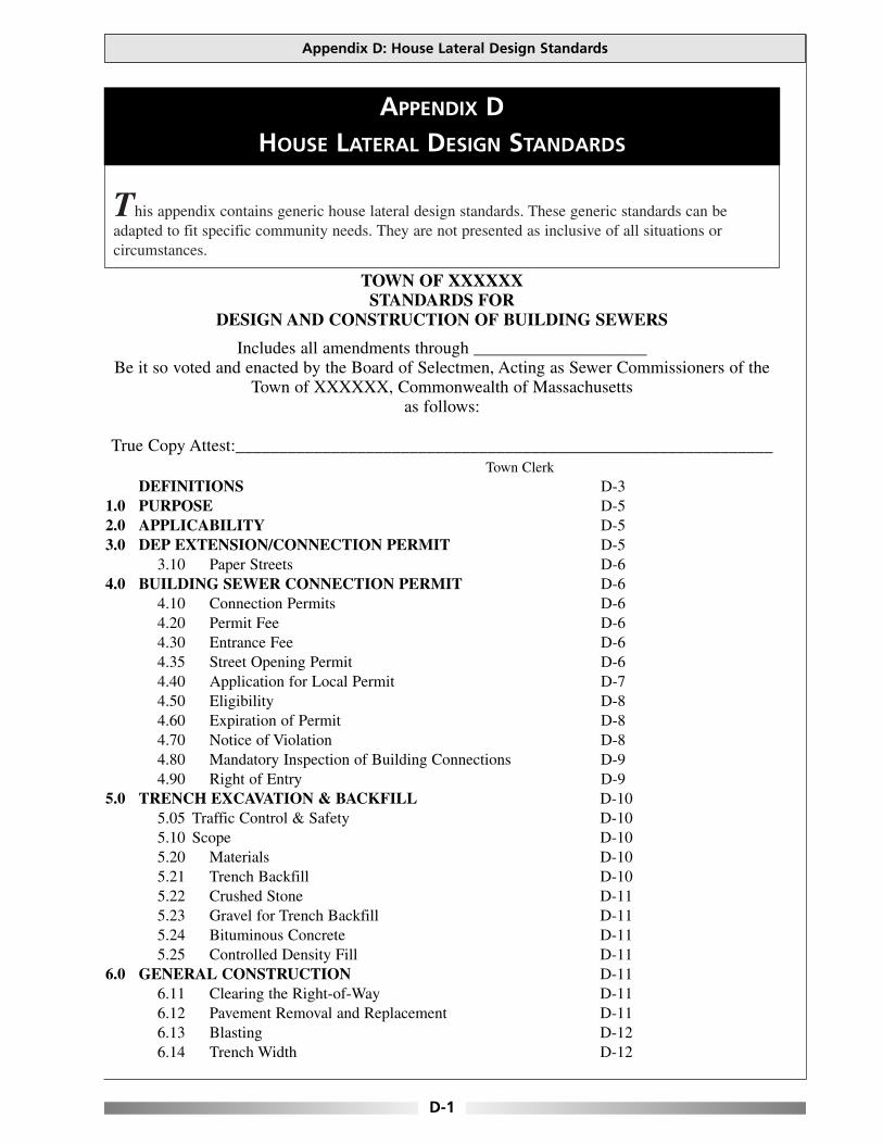
This appendix contains generic house lateral design standards. These generic standards can beadapted to fit specific community needs. They are not presented as inclusive of all situations orcircumstances.
Appendix D: House Lateral Design Standards
D-1
APPENDIX DHOUSE LATERAL DESIGN STANDARDS
TOWN OF XXXXXXSTANDARDS FOR
DESIGN AND CONSTRUCTION OF BUILDING SEWERS
Includes all amendments through ____________________Be it so voted and enacted by the Board of Selectmen, Acting as Sewer Commissioners of the
Town of XXXXXX, Commonwealth of Massachusetts as follows:
True Copy Attest:______________________________________________________________Town Clerk
DEFINITIONS D-31.0 PURPOSE D-52.0 APPLICABILITY D-53.0 DEP EXTENSION/CONNECTION PERMIT D-5
3.10 Paper Streets D-64.0 BUILDING SEWER CONNECTION PERMIT D-6
4.10 Connection Permits D-64.20 Permit Fee D-64.30 Entrance Fee D-64.35 Street Opening Permit D-64.40 Application for Local Permit D-74.50 Eligibility D-84.60 Expiration of Permit D-84.70 Notice of Violation D-84.80 Mandatory Inspection of Building Connections D-94.90 Right of Entry D-9
5.0 TRENCH EXCAVATION & BACKFILL D-105.05 Traffic Control & Safety D-105.10 Scope D-105.20 Materials D-105.21 Trench Backfill D-105.22 Crushed Stone D-115.23 Gravel for Trench Backfill D-115.24 Bituminous Concrete D-115.25 Controlled Density Fill D-11
6.0 GENERAL CONSTRUCTION D-116.11 Clearing the Right-of-Way D-116.12 Pavement Removal and Replacement D-116.13 Blasting D-126.14 Trench Width D-12

6.15 Grade D-126.16 Shoring, Sheeting & Boxing of Trenches D-126.17 Location of Excavated Materials D-126.18 Removal of Water D-136.19 Trench Backfill Compaction D-136.20 Excess Excavated Material D-136.21 Rock Excavation D-136.22 Controlled Density Fill D-13
7.0 SEWER PIPE INSTALLATION D-147.10 Scope D-147.20 Materials D-14
8.0 INSTALLATION REQUIREMENTS D-158.10 Permit D-158.20 Licensed Contractors D-158.30 Minimum Size, Fittings and Clean-outs D-158.40 Minimum Elevations for Gravity Connection D-168.50 Future Connections D-168.60 Grease Traps D-16
9.0 WORKMANSHIP D-169.10 Preparation of Trench D-169.20 Preparation of Sewer Pipe D-179.30 Laying and Jointing Pipe and Fittings D-179.35 Sewer Installation D-17
10.0 VACUUM TEST D-1810.10 Preparation of the Manhole D-1810.20 Procedure D-19
11.0 MANHOLE AND CLEANOUT CONSTRUCTION D-1911.10 Scope D-1911.20 Materials D-1911.21 Concrete D-1911.22 Precast Manhole Sections D-1911.23 Precast Concrete Bases D-1911.24 Special Fittings D-1911.25 Manhole Frames & Covers D-1911.26 Manhole Steps D-2011.27 Manhole Blockouts/Plugged Boot D-2011.28 Manhole Tables D-2011.29 Manhole Inverts D-2011.30 Drop Manholes D-20
12.0 GRINDER PUMPS & SEWERAGE EJECTORS D-2012.10 Force Main Connections D-21
13.0 SEWER EASEMENTS D-2114.0 PROTECTION OF WATER SUPPLY D-22
14.10 Well Areas-Zone II D-2315.0 PIPE JACKING & DIRECTIONAL DRILLING D-23
15.10 Pipe Jacking D-2315.20 Horizontal Directional Drilling D-2315.25 Boring Path Report D-2315.30 Vacuum Holes D-23
16.0 VALIDITY D-24
Optimizing Operation, Maintenance, and Rehabilitation of Sanitary Sewer Collection Systems
D-2

DEFINITIONS:
Appurtenance shall mean any piece associated with the physical operation of the XXXXXXSewerage System.
ASTM shall mean the material standard of the American Society for Testing and Materials.
Authority shall mean the Massachusetts Water Resources Authority.
Board shall mean the Board of Selectmen, acting as Sewer Commissioners, or their authorizedagent.
Building Sewer shall mean the extension from the interior plumbing to the public sewer or otherplace of disposal. The building sewer extends from the foundation at the building to the propertyline.
CDF shall mean controlled density fill or flowable fill.
Concentric shall mean the relationship between two different circular, cylindrical sewer pipes,when one is exactly centered within the other.
DEP shall mean the Massachusetts Department of Environmental Protection.
Engineer shall mean any person who is licensed by the Commonwealth of Massachusetts toperform professional engineering services.
EPA shall mean the United States Environmental Protection Agency.
Garage shall mean any structure or property where one or more motor vehicles are kept, stored, orserviced, including a public or private garage, carport, motor vehicle repair shop, paint shop,service station, lubritorium, car wash, gasoline station with grease pits or wash racks or areas, orany building used for similar purposes.
Infiltration shall mean the water entering a Sewerage System from the ground or a water body,including through such means as, defective building drains and sewers, pipes, pipe joints,connections, or manhole walls.
Inflow shall mean the discharge into a Sewerage System, including service connections, from suchsources including, but not limited to: roof leaders, cellars, yards, and area drains, foundationdrains, sump pumps, Cooling Water discharges, drains from springs, and swampy areas, manholecovers, cross connections from Storm Sewers and Combined Sewers, catch basins, storm water,surface runoff, or street wash water.
Lot shall mean an area of land in one ownership, with definite boundaries used, or available foruse, as the site of one or more buildings.
May is permissive; shall is mandatory.
MWRA shall mean the Massachusetts Water Resources Authority.
MWRA Service Area shall mean the area consisting of the following political subdivisions:Arlington, Ashland, Bedford, Belmont, Boston, Braintree, Brookline, Burlington, Cambridge,Canton, Chelsea, Dedham, Everett, Framingham, the north sewer district of Hingham, Holbrook,Lexington, Malden, Medford, Melrose, Milton, Natick, Needham, Newton, Norwood, Quincy,Randolph, Reading, Revere, Somerville, Stoneham, Stoughton, Wakefield, Walpole, Waltham,Watertown, Wellesley, Westwood, Weymouth, Wilmington, Winchester, Winthrop, and Woburn.
M.G.L. shall mean Massachusetts General Law.
Owner shall mean the person(s) holding fee simple title to a parcel, tract or lot of land, as shown bythe record in the appropriate Land Registration Office, Registry of Deeds or Registry of Probate.
Appendix D: House Lateral Design Standards
D-3
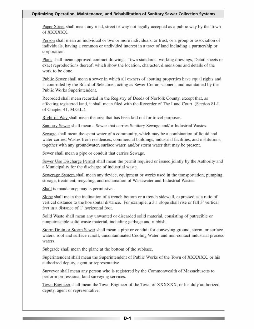
Paper Street shall mean any road, street or way not legally accepted as a public way by the Townof XXXXXX.
Person shall mean an individual or two or more individuals, or trust, or a group or association ofindividuals, having a common or undivided interest in a tract of land including a partnership orcorporation.
Plans shall mean approved contract drawings, Town standards, working drawings, Detail sheets orexact reproductions thereof, which show the location, character, dimensions and details of thework to be done.
Public Sewer shall mean a sewer in which all owners of abutting properties have equal rights andis controlled by the Board of Selectmen acting as Sewer Commissioners, and maintained by thePublic Works Superintendent.
Recorded shall mean recorded in the Registry of Deeds of Norfolk County, except that, asaffecting registered land, it shall mean filed with the Recorder of The Land Court. (Section 81-Lof Chapter 41, M.G.L.).
Right-of-Way shall mean the area that has been laid out for travel purposes.
Sanitary Sewer shall mean a Sewer that carries Sanitary Sewage and/or Industrial Wastes.
Sewage shall mean the spent water of a community, which may be a combination of liquid andwater-carried Wastes from residences, commercial buildings, industrial facilities, and institutions,together with any groundwater, surface water, and/or storm water that may be present.
Sewer shall mean a pipe or conduit that carries Sewage.
Sewer Use Discharge Permit shall mean the permit required or issued jointly by the Authority anda Municipality for the discharge of industrial waste.
Sewerage System shall mean any device, equipment or works used in the transportation, pumping,storage, treatment, recycling, and reclamation of Wastewater and Industrial Wastes.
Shall is mandatory; may is permissive.
Slope shall mean the inclination of a trench bottom or a trench sidewall, expressed as a ratio ofvertical distance to the horizontal distance. For example, a 3:1 slope shall rise or fall 3’ verticalfeet in a distance of 1’ horizontal foot.
Solid Waste shall mean any unwanted or discarded solid material, consisting of putrecible ornonputrescible solid waste material, including garbage and rubbish.
Storm Drain or Storm Sewer shall mean a pipe or conduit for conveying ground, storm, or surfacewaters, roof and surface runoff, uncontaminated Cooling Water, and non-contact industrial processwaters.
Subgrade shall mean the plane at the bottom of the subbase.
Superintendent shall mean the Superintendent of Public Works of the Town of XXXXXX, or hisauthorized deputy, agent or representative.
Surveyor shall mean any person who is registered by the Commonwealth of Massachusetts toperform professional land surveying services.
Town Engineer shall mean the Town Engineer of the Town of XXXXXX, or his duly authorizeddeputy, agent or representative.
Optimizing Operation, Maintenance, and Rehabilitation of Sanitary Sewer Collection Systems
D-4

1.0 Purpose
These specifications are intended to protect the public health, safety and welfare and the environmentand to ensure proper and safe operation of the XXXXXX Municipal Sewer System by regulating thedirect and indirect discharge of wastewater and pollutants to the Sewerage System in accordance with360 CMR 10.000, the XXXXXX Code Sewer Use and the Rules & Regulations relating to PrivateSewers adopted by the Board of Selectmen on __________.
In the absence of code provisions or in amplification thereof, the materials and procedures as set forthin appropriate specifications shall apply:
• American Society of Testing Material (ASTM), and the Water Pollution Control Federation(WPCF) Manual of Practice No.7, “Operation and Maintenance of Wastewater CollectionSystems”.
• American Society of Civil Engineers (ASCE), Manuals and Reports in Engineering PracticeNo.60, “Gravity Sanitary Sewer Design and Construction”.
The XXXXXX Public Works Superintendent shall, in the case of any discrepancies or questions,direct the Contractor accordingly.
2.0 Applicability
Every person who directly or indirectly discharges Wastewater to the Authority Sewerage System shallensure that such discharge complies with 360 CMR 10.000. The requirements of 360 CMR 10.000apply to direct discharges to the Authority Sewerage System and to discharges to the AuthoritySewerage System through a municipal sewer.
3.0 DEP Extension/Connection Permit
No person shall connect to a Municipal Sewer System or an Authority Sewer, or construct, effect,modify, or maintain a Sewer extension or connection, without a sewer system connection permitissued by the Board of Selectmen acting as Sewer Commissioners, or extension/connection permit ifrequired by DEP pursuant to M.G.L. c.21§ 43 and 314 CMR 7.00, 360 CMR 10.000 in where such apermit is required.
Permit requirements are published by the DEP, referenced by the application categories in thefollowing table:
DEP Permit Application Categories: 310 CMR 4.00
BRP WP 13 Major Sewer Extension
BRP WP 14 Minor Sewer Extension; Connect w/Pump Station
BRP WP 17 Major Sewer Connection (≥ 50,000 gpd)
BRP WP 55 Industrial Wastewater
All sewer extensions shall have a plan prepared by a Registered Professional Engineer in theCommonwealth of Massachusetts. The Department of Environmental Protection (DEP) must approvethe Sewer Extension before the Town will issue any Sewer Connection or Street Opening Permits.
Appendix D: House Lateral Design Standards
D-5
3.10 Paper Streets
Paper Street Sewers and appurtenances shall comply with the Street and Sewer-Commissioners. All sewer design and construction work proposed or performed in paperstreets, shall comply with the Town of XXXXXX Land Subdivision Regulations.
4.0 Building Sewer Connection Permit
4.10 Connection Permits
A Sewer Connection Permit shall be issued by the Town of XXXXXX EngineeringDepartment for all repairs, modifications or connections to the XXXXXX Sewer System. Inaddition, Sewer Connection Permits are required for the expansion of any existing buildingconnected to the system which requires alteration or retrofit of the existing sewer or any ofits direct appurtenances.
All costs and expense(s) incident to the installation and connection of the building sewer shallbe borne by the owner. The owner shall indemnify the Town from any loss or damage thatmay directly or indirectly be occasioned by the installation of the building sewer.
No unauthorized person shall maliciously, willfully or negligently break, damage, destroy,uncover, deface or tamper with any structure, appurtenance or equipment which is a part ofthe sewerage works. Any person violating this provision shall be subject to immediate arrestunder charge of disorderly conduct. Please note DIGSAFE-1-888-344-7233.
4.20 Permit Fee
A fee of $50.00 per residential dwelling unit and a fee of $75.00 per non-residential unit shallbe charged for each Permit. This permit includes up to three (3) inspections. Additionalinspections, if required, due to defective workmanship or incomplete construction will beassessed a re-inspection fee of an equal amount.
4.30 Entrance Fee
An entrance fee of $300.00, shall be charged for any new single connection to the SewerSystem. The fee shall be deposited in the Sewer Enterprise Fund.
4.35 Street Opening Permit
Contractor shall obtain a Street Opening Permit from the Department of Public Works. Ifconstruction of the building sewer requires construction in a traveled way of a street or workwithin the Right of Way. The contractor shall post a bond in an amount determined by thePublic Works Superintendent; said bond to be released only on final approval from theSuperintendent of Public Works. The Contractor shall restore the street trench with atemporary patch of bituminous concrete within twenty-four (24) hours. If flowable fill wasplaced in a trench, subsequent trench repair is to be placed within thirty (30) days of thetemporary patch.
Optimizing Operation, Maintenance, and Rehabilitation of Sanitary Sewer Collection Systems
D-6

4.40 Application for Local Permit
1. A Permit application for any sewer extension must be made on the form prescribed bythe Town of XXXXXX Engineering Department. Once a signed permit from theXXXXXX Engineering Department has been issued to the contractor, the entrance feeshall be paid to the P.W.D. where applicable. A Street Opening Permit must be obtainedfrom the Public Works Department wherever a street is to be opened, or pursuant to thefollowing:
a. Any easements required for construction of the connection must be approved by theEngineering Department prior to issuance of the Permit.
b. Any Sewer Extension in a right-of-way, easement or paper street, must be designedby a Registered Professional Engineer in the State of Massachusetts. Plans shall beto scale, and approved by the Engineering Department prior to issuance of thePermit. This permit shall not supercede any DEP requirements for an extensionpermit.
c. Once DEP has issued an Extension Permit.
2. The application will require at a minimum, the following information:
a. Name and address of the Owner;
b. Name, address and telephone number of the Contractor;
c. Address of work site;
d. If required, a legal description of the Owner’s property for which the Permit is beingrequested;
e. Dig-Safe Number;
f. Number of bedrooms in the house to be serviced by the Sewer Connection;
g. If required by the Town Engineer or Public Works Superintendent, plans shall besubmitted by a Professional Engineer to the Engineering Department for review forthe Building Sewer and connection, which at a minimum must consist of thefollowing:
1. Plot plan according to XXXXXX Board of Health standards.
2. Connection details including location of connection and routing of the buildingsewer, profile of connection, and the material(s) of construction for the buildingsewer.
3. Elevation of the first floor and lowest point of gravity service.
Appendix D: House Lateral Design Standards
D-7
4.50 Eligibility
The Town of XXXXXX shall issue permits to contractors licensed to perform excavation inthe Town of XXXXXX.
NOTE: The Town of XXXXXX may deny Permits to any applicant who has previouslyviolated, or is currently in violation of, these Standards or any other XXXXXX rules,regulations, standards, specifications or details described herein.
4.60 Expiration of Permit
a. The Permit will expire if the work is not initiated within one hundred eighty (180) daysfrom the date of issuance. Upon Permit expiration, a new Permit, including payment ofthe Permit fee, will be required for the future connection and inspection(s).
b. The Town of XXXXXX, may extend the duration of the Permit for a reasonable period.Requests for extension of the Permit period must be submitted in writing to the XXXXXXEngineering Department in advance of the expiration and must state the reason for request.Requests for extension must be forwarded to:
Town EngineerTown of XXXXXX
Attn: Sewer Connection Permit
4.70 Notice of Violation
The Town will issue a “Notice of Violation” whenever it determines that:
1. Contractor is performing work without proper licensure.
2. Contractor is in non-compliance with the Rules and Regulations set forth by theDepartment of Public Safety.
3. If construction is proceeding in a manner that jeopardizes public safety.
4. Construction is occurring in violation of these Standards and/or any other applicableapproved specifications or details. Sewer construction is proceeding without a validpermit.
5. Connection of any source of clear water to the Building Sewer.
6. A discharge, into the Town of XXXXXX Sewerage System, of any prohibited water orwastes as defined in 360 CMR 10.000.
7. Work taking place in a right-of-way without a proper police detail, subject to the Townof XXXXXX Police Chief’s approval.
8. Damage, debris, and or soils in the roadway resulting from the work.
Any person found to be violating any provision of these Regulations shall be served by theTown with written notice stating the nature of the violation and provided with a reasonabletime limit for the satisfactory correction thereof. The offender shall, within the period of timestated in such notice, permanently cease and correct all violations.
Optimizing Operation, Maintenance, and Rehabilitation of Sanitary Sewer Collection Systems
D-8
These regulations shall be enforced by employees of the XXXXXX Sewer Department orXXXXXX Engineering Department, by means of a non-criminal disposition pursuant toM.G.L. Chapter 40, Section 21D.
Any person who shall continue any violation beyond the time limit provided for in Section4.70, shall be subject to a penalty of $50.00. Each day in which any such violation shallcontinue shall be deemed a separate offense. (amended October 18, 1994)
Any person violating any of the provisions of these Regulations shall become liable to theTown for any expense, loss or damage occasioned the Town by reason of such violations.
4.80 Mandatory Inspection of Building Connections
1. Notification
The Contractor shall notify the Engineering Department that the sewer work is availablefor inspection. Notification to be provided at least twenty-four (24) hours beforeinspection is desired. The Engineering Department will perform inspections on Sewersfrom 8:30 a.m. to 4:30 p.m., Monday through Wednesday, Thursdays from 8:30 a.m. to5:30 p.m., and on Friday from 8:30 a.m. to 12:00 p.m. Or as agreed to in advance withthe Engineering Department.
It is the responsibility of the Contractor to ensure that the connection is inspected, in itsentirety, from the foundation to the connection with the public sewer or existing lateral,work must be exposed for inspection and be constructed in accordance with thesestandards. Under no circumstance shall the Sewer work be backfilled without aninspection by the Engineering Department or its authorized representative.
The Public Works Department or the Engineering Department may require re-excavationof a buried sewer utility if an inspection was not performed at the time of installation.
2. Video Camera Inspection
The Engineering Department or Public Works Department may, at their discretion,require the connection to be inspected using closed circuit television equipment. TheXXXXXX Public Works Department shall perform the video camera inspection andinspect for, but not limited to, the following:
a. Joint separation. b. Construction debris in line sewer.c. Properly installed joints.d. Deformed pipes.e. Cracks in pipes.f. Infiltration.g. Number of fittings and distance between manholes.h. Illegal discharge of clear water.
4.90 Right of Entry
An authorized representative of the Town of XXXXXX shall have the right of entry to, uponor through the Owner’s Premises for purposes of inspecting Building Sewers or to determineif any sources of clear water are connected to the Building Sewer.
Appendix D: House Lateral Design Standards
D-9

5.0 Trench Excavation and Backfill
5.05 Traffic Control & Safety
1. All excavations for building sewer installation shall be adequately guarded withbarricades and lights so as to protect the public from hazard. Streets, sidewalks,parkways and other public property disturbed in the course of the work shall be restoredin a manner satisfactory to the Town.
2. If work is being performed in a traveled way, it shall be at the discretion of the Chief ofPolice to require an assigned Police Detail to any and all work performed in the travelway.
3. Any work within a State Highway shall be coordinated with the Massachusetts HighwayDepartment.
4. When required, the owner of any property serviced by a building sewer carryingindustrial wastes shall install a suitable control manhole together with such necessarymeters, and other appurtenances in the building sewer to facilitate observation, sampling,and measurement of wastes. Such manhole, when required, shall be accessible and safelylocated and shall be maintained by the owner so as to be safe and accessible at all times.
5.10 Scope
This item covers the work necessary for the trench excavation and backfill, complete,including but not limited to: clearing of right of way; protection of private property duringconstruction; disposal of cleared materials; excavation of trench for the pipe andappurtenances; foundation stabilization; backfilling the pipe; trench backfilling above thepipe; removal, replacement, and rehabilitation of all fences, drainage ditches, waterways,culverts, concrete curbs and sidewalks, or other features moved or damaged duringconstruction; removal of all obstructions; removal of existing pavement; locating andprotecting existing utilities; repair of damage to utilities; the maintenance of access to publicthoroughfares and to private property; the maintenance of adequate barricades, lights, andwarning signs for the protection of the public on public right-of-ways, streets and privatedrives; shoring, cribbing, bracing, sheeting, and dewatering as may be required; hauling anddisposal of waste excavation, including temporary hauling and disposal of soil which cannotbe accommodated within the designated right of way; repair of public and private propertydamaged during construction; final cleanup of the construction area; restoration of thelandscape in public rights of way including replacement of lawns, grasses, trees, shrubs andmulches; and all miscellaneous items of work required to complete the construction specifiedhereunder, in accordance with 360 CMR 10.000, Massachusetts Highway StandardSpecifications 120.60, and the Town of XXXXXX Land Subdivision Regulations.
5.20 Materials
5.21 Trench Backfill
Placement of backfill material shall include the working of material to achieve suitablemoisture content and compaction to the specified density in accordance with MassachusettsHighway Dept. Standard Specifications (Spec.150.60, backfilling for structures and pipes).
Imported material must be approved by the XXXXXX Engineering Department prior toplacement. Material shall be granular fill, gravel, rock, or combinations thereof, free ofhumus, organic matter, vegetative matter, frozen material, clods, sticks, and debris andcontaining no stones having a dimension greater than four (4) inches. Sand or pea stone will
Optimizing Operation, Maintenance, and Rehabilitation of Sanitary Sewer Collection Systems
D-10
not be an approved backfill material. No backfill shall be placed on or against structures,pipes, or any other masonry until a visual inspection has been performed by the XXXXXXEngineering Department or its authorized agent.
Unacceptable material shall be removed at the direction of the Town Engineer.
5.22 Crushed Stone
Material for pipe base shall be 3/4 inch minus crushed stone, having reasonably evengradation from coarse to fine, in accordance with the Massachusetts Highway DepartmentStandard Specifications for Highways and Bridges specification for Aggregates and relatedmaterials M2.010 (Sect. 230.61).
5.23 Gravel for Trench Backfill
Gravel for trench backfill shall be clean pit run gravel, crushed rock or gravel having areasonable even gradation from coarse to fine. The maximum size shall be four (4) inches.
5.24 Bituminous Concrete
Asphaltic concrete shall be hot plant mix, type I-1 material conforming to the requirementsof MA Highway Section 420, entitled, “Class I Bituminous Concrete Base Course” of theStandard Specifications of the Massachusetts Highway Dept. Contractor shall replacebituminous concrete in two lifts, binder and wearing course in thickness’ equal to the existingbinder but in no case less than 2.5” binder and 1.5” wearing course.
5.25 Controlled Density Fill
Controlled Density Fill (CDF) where required, shall be a mixture of Portland cement, fly ash,aggregates, water and admixtures proportioned to provide a non-segregating, self-consolidating, free-flowing and excavatable material that will result in a hardened, dense,non-settling fill. CDF is approved as an alternative to “Gravel for Trench Backfill” and as analternative to “Crushed Gravel” and may be used at any location on the project at the optionof the contractor for stabilization material, pipe base material, pipe zone material, trenchbackfill material and pavement base material. The use of CDF is required for backfillmaterial associated with outside drop manholes, and any construction in paved roadwayshaving been paved or surfaced within five (5) years, or at the discretion of the XXXXXXPublic Works Superintendent.
6.0 General Construction
6.11 Clearing the Right of Way
Where clearing of the right of way is necessary, it shall be completed prior to the start of thetrenching. Trees and brush shall be cut as near to the surface of the ground as practicable andpiled for disposal. Contractor shall remove all organic material, grub stumps and strip loam& subsoil to granular mineral material. The Contractor shall observe all state laws relatingto fire permits and local regulations relating to burning such materials. Under no conditionsshall excavated materials be permitted to cover brush or trees prior to clearing and disposal.In accordance with Massachusetts Highway Dept. Standard Specifications (Sect 101).
6.12 Pavement Removal and Replacement
All bituminous and concrete pavements, regardless of the thickness, shall be saw-cut where
Appendix D: House Lateral Design Standards
D-11

required prior to excavation of trenches. Width of the pavement cut shall be at least six (6)inches greater than the required width of the trench at ground surface on each side. Pavementremoved during excavation shall be piled separately from the earth spoil and removed fromthe site and shall not be used in backfilling the trench.
After the trench has been backfilled and compacted according to the design specifications,the Contractor shall bring the trench to a smooth even grade at the proper depth below theexisting surface to provide for the required depth of pavement. The Contractor shall saw-cutthe existing pavement to a straight line and remove any pavement that has been damagedduring work as required by the Superintendent of Public Works and or the EngineeringDepartment.
The entire existing paved surface shall be cleaned and the sawn edges prepared with tackbefore resurfacing is begun. The trench shall be repaired per the specifications set forth inthe Street Opening Permit issued by the XXXXXX Public Works Department.
6.13 Blasting
Blasting for excavation will be permitted only after securing approval of the XXXXXX FireDepartment and only when proper precautions are taken for the protection of persons andproperty. Any damages caused by the blasting shall be repaired by the Contractor at his ownexpense. The Contractor’s methods of procedure and blasting shall conform to all applicableState laws and municipal ordinances.
6.14 Trench Width
In all cases, trench width shall be confined to dedicated right-of-way for public thoroughfaresor within areas for which construction easements have been obtained, unless specialarrangements have been made with the affected property owners beforehand and approved bythe Engineering Department.
6.15 Grade
The bottom of the trench shall be carried to the lines and grades shown on the Plans or asestablished by the design Engineer, with proper allowance for pipe thickness and for properbedding.
6.16 Shoring, Sheeting, and Boxing of Trenches
Whenever necessary to prevent caving during excavation in gravel, sandy soil, or otherunstable material, the trench shall be adequately sheeted and braced. Failure to comply withproper applicable OSHA standards with regard to; sheeting, shoring, or bracing shall be causefor a Notice of Violation. All sheeting, shoring and bracing of trenches shall conform to thosestandard requirements.
6.17 Location of Excavated Materials
During trench excavation, the Contractor shall locate the excavated material so it will notobstruct a traveled roadway or street; and, unless otherwise approved by the Public WorksSuperintendent, all streets and roadways shall be kept open to at least one-way traffic, or asdirected by the XXXXXX Police Department.
Optimizing Operation, Maintenance, and Rehabilitation of Sanitary Sewer Collection Systems
D-12

6.18 Removal of Water
The Contractor shall provide and maintain ample means and devices with which to promptlyremove and properly dispose of all water, including flow from existing sewer lines, enteringthe trench excavation during the time the trench is being prepared for the pipe laying, duringthe laying of the pipe, and inspection, until the backfill above the pipe has been completedaccordingly.
The Contractor shall be responsible for dewatering the trench. If the Contractor wishes to de-water into the Towns drainage system, the XXXXXX Engineering Department must approveany and all means for the transfer, treatment and disposal thereof before any discharge occurs.
The Contractor shall dispose of the water and or sewage in accordance with state and localregulations. Precautions against sedimentation control must be maintained at all times.
6.19 Trench Backfill Compaction
After the Contractor has backfilled the pipe zone of the trench as required, he shall thenbackfill the balance of the trench, mechanically compacting each layer to 95% of maximumdensity in roadways and 85% to 90% in all other areas. Where fill is required, use bank-rungravel per M1.03.0 (a six-inch maximum diameter stone size).
A cash bond to be determined by the Public Works Superintendent is to be posted for trenchesthat do not require flowable fill (CDF). After a period of one year, or at the discretion of theSuperintendent of Public Works, the Contractor must replace the pavement. After such a timethe Public Works will inspect the work and determine if the bond shall be released.
Any subsequent settlement of the trench or ditch during the above referenced time frame shallbe considered to be the result of improper compaction and shall be corrected at no expenseto the Town by the contractor.
6.20 Excess Excavated Material
All excess excavated materials shall be hauled and properly disposed of by the Contractor.The Contractor shall make his own arrangements for the disposal of the excavated material.
6.21 Rock Excavation
Before proceeding with rock excavation, the Contractor shall have completed the commonexcavation to such depths that only rock excavation remains. At this time the trench shall bemade available to the design Engineer and measurements will be taken to determine theamount of rock excavation remaining. Any redirection of the sewer connection to avoid ledgeoutcrops must be approved by the Engineering Department.
6.22 Controlled Density Fill
Controlled Density Fill (CDF) where required, shall be a mixture of Portland cement, fly ash,aggregates, water and admixtures proportioned to provide a non-segregating, self-consolidating, free-flowing and excavatable material that will result in a hardened, dense,non-settling fill.
The use of CDF is required for backfill material associated with outside drop manholes, andany construction in paved roadways having been paved or surfaced within five (5) years, orat the discretion of the XXXXXX Public Works Superintendent.
Appendix D: House Lateral Design Standards
D-13

1. Placement
CDF is a heavy material and during placement will exert a high fluid pressure against anypipe, manhole, or other material it contacts. The resultant pressure will tend to cause pipeand manholes to float or shift. CDF shall be placed in such a manner as to preventflotation or shifting of pipe and manholes. CDF shall not be placed on frozen ground orduring a time when the air temperature is 38 ºF or less and falling.
No CDF shall be placed under water.
2. Curing
Contractor shall provide steel plates k-36 steel (k-56 recommended) to span trenches orotherwise prevent traffic or construction equipment coming in contact with CDF until theCDF has hardened sufficiently to prevent rutting. Contractor shall provide cold patch onall edges of steel plates used for vehicular transition in any affected area.
7.0 Sewer Pipe Installation
7.10 Scope
This item shall include the work necessary for the installation of sewer pipe and fittings ofthe sizes and classes indicated, including but not limited to furnishing materials, placingcrushed gravel pipe base, providing bell holes in the trench bottom; laying and jointing thepipe; installing sewer tees, wyes and laterals; furnishing pipe necessary for physical test; andtesting of the line. Ductile iron pipe shall be used when the sewer line is less than three (3)feet below existing finished grade.
7.20 Materials
1. PVC Sewer Pipe
Pipe used for sewers shall be PVC. The pipe shall be of the size and type indicated onthe plans and shall conform to the appropriate specifications detailed below. Pipe andfittings used in Building Sewer construction shall be smooth wall inside and out, andmust be either: Polyvinyl Chloride (“PVC”) and must conform to ASTM D-3034 (SDR35; or ASTM D-1785-99 (Schedules 40 or 80)). All pipe must have a minimum tensilestrength of 34.50 Mpa as defined by ASTM D-1784. SDR rating is the ratio of theoutside diameter to the pipe wall thickness.
2. Ductile Iron Pipe
Ductile iron (DI) pipe must meet ASTM A-746-99 (pressure class 350) or AWWA C-151(pressure class 350) with exterior asphaltic coating per AWWA C-151 and interiorasphaltic coating meeting AWWA C-151 or polyethylene lining complying with ASTMD-1248 of nominal 40-mil thickness.
Optimizing Operation, Maintenance, and Rehabilitation of Sanitary Sewer Collection Systems
D-14
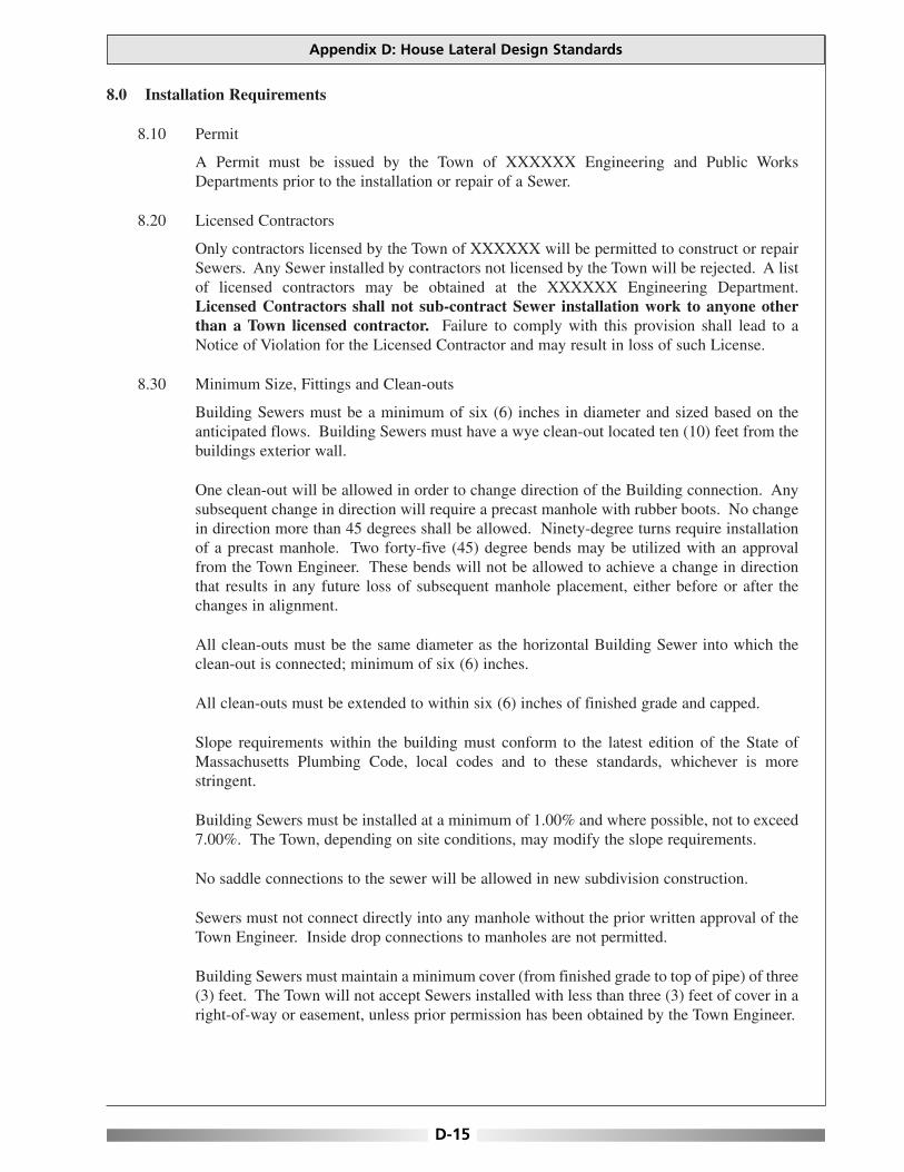
8.0 Installation Requirements
8.10 Permit
A Permit must be issued by the Town of XXXXXX Engineering and Public WorksDepartments prior to the installation or repair of a Sewer.
8.20 Licensed Contractors
Only contractors licensed by the Town of XXXXXX will be permitted to construct or repairSewers. Any Sewer installed by contractors not licensed by the Town will be rejected. A listof licensed contractors may be obtained at the XXXXXX Engineering Department.Licensed Contractors shall not sub-contract Sewer installation work to anyone otherthan a Town licensed contractor. Failure to comply with this provision shall lead to aNotice of Violation for the Licensed Contractor and may result in loss of such License.
8.30 Minimum Size, Fittings and Clean-outs
Building Sewers must be a minimum of six (6) inches in diameter and sized based on theanticipated flows. Building Sewers must have a wye clean-out located ten (10) feet from thebuildings exterior wall.
One clean-out will be allowed in order to change direction of the Building connection. Anysubsequent change in direction will require a precast manhole with rubber boots. No changein direction more than 45 degrees shall be allowed. Ninety-degree turns require installationof a precast manhole. Two forty-five (45) degree bends may be utilized with an approvalfrom the Town Engineer. These bends will not be allowed to achieve a change in directionthat results in any future loss of subsequent manhole placement, either before or after thechanges in alignment.
All clean-outs must be the same diameter as the horizontal Building Sewer into which theclean-out is connected; minimum of six (6) inches.
All clean-outs must be extended to within six (6) inches of finished grade and capped.
Slope requirements within the building must conform to the latest edition of the State ofMassachusetts Plumbing Code, local codes and to these standards, whichever is morestringent.
Building Sewers must be installed at a minimum of 1.00% and where possible, not to exceed7.00%. The Town, depending on site conditions, may modify the slope requirements.
No saddle connections to the sewer will be allowed in new subdivision construction.
Sewers must not connect directly into any manhole without the prior written approval of theTown Engineer. Inside drop connections to manholes are not permitted.
Building Sewers must maintain a minimum cover (from finished grade to top of pipe) of three(3) feet. The Town will not accept Sewers installed with less than three (3) feet of cover in aright-of-way or easement, unless prior permission has been obtained by the Town Engineer.
Appendix D: House Lateral Design Standards
D-15
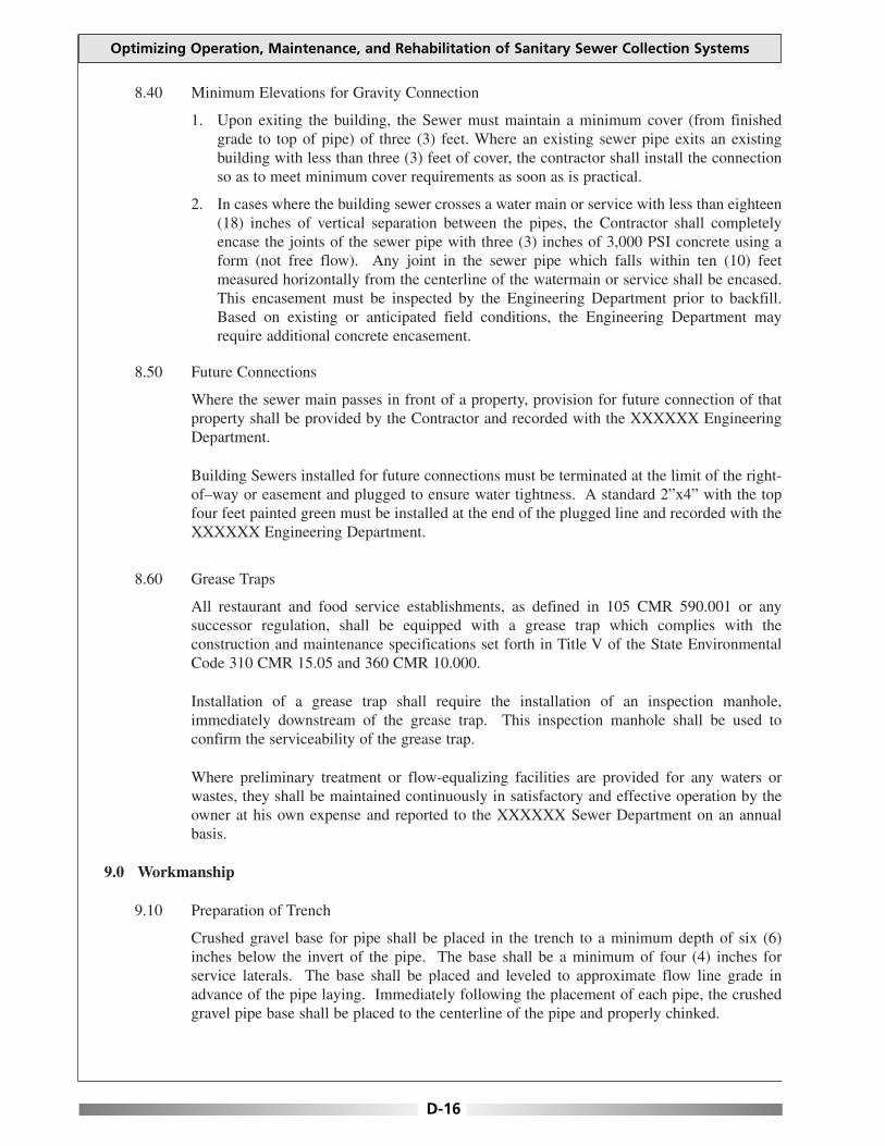
8.40 Minimum Elevations for Gravity Connection
1. Upon exiting the building, the Sewer must maintain a minimum cover (from finishedgrade to top of pipe) of three (3) feet. Where an existing sewer pipe exits an existingbuilding with less than three (3) feet of cover, the contractor shall install the connectionso as to meet minimum cover requirements as soon as is practical.
2. In cases where the building sewer crosses a water main or service with less than eighteen(18) inches of vertical separation between the pipes, the Contractor shall completelyencase the joints of the sewer pipe with three (3) inches of 3,000 PSI concrete using aform (not free flow). Any joint in the sewer pipe which falls within ten (10) feetmeasured horizontally from the centerline of the watermain or service shall be encased.This encasement must be inspected by the Engineering Department prior to backfill.Based on existing or anticipated field conditions, the Engineering Department mayrequire additional concrete encasement.
8.50 Future Connections
Where the sewer main passes in front of a property, provision for future connection of thatproperty shall be provided by the Contractor and recorded with the XXXXXX EngineeringDepartment.
Building Sewers installed for future connections must be terminated at the limit of the right-of–way or easement and plugged to ensure water tightness. A standard 2”x4” with the topfour feet painted green must be installed at the end of the plugged line and recorded with theXXXXXX Engineering Department.
8.60 Grease Traps
All restaurant and food service establishments, as defined in 105 CMR 590.001 or anysuccessor regulation, shall be equipped with a grease trap which complies with theconstruction and maintenance specifications set forth in Title V of the State EnvironmentalCode 310 CMR 15.05 and 360 CMR 10.000.
Installation of a grease trap shall require the installation of an inspection manhole,immediately downstream of the grease trap. This inspection manhole shall be used toconfirm the serviceability of the grease trap.
Where preliminary treatment or flow-equalizing facilities are provided for any waters orwastes, they shall be maintained continuously in satisfactory and effective operation by theowner at his own expense and reported to the XXXXXX Sewer Department on an annualbasis.
9.0 Workmanship
9.10 Preparation of Trench
Crushed gravel base for pipe shall be placed in the trench to a minimum depth of six (6)inches below the invert of the pipe. The base shall be a minimum of four (4) inches forservice laterals. The base shall be placed and leveled to approximate flow line grade inadvance of the pipe laying. Immediately following the placement of each pipe, the crushedgravel pipe base shall be placed to the centerline of the pipe and properly chinked.
Optimizing Operation, Maintenance, and Rehabilitation of Sanitary Sewer Collection Systems
D-16

9.20 Preparation of Sewer Pipe
All pipes and fittings shall be carefully inspected before being laid and no cracked, broken ordefective pipe or fittings shall be used in the work. The ends of the pipe shall be cleaned witha brush, washed and thoroughly scrubbed where necessary to remove dirt or other foreignmaterial.
Extreme care shall be exercised to insure that the inside surfaces of the bell are smooth andfree from any projections which would interfere with the assembly or water tightness of thejoint.
9.30 Laying and Jointing Pipe and Fittings
Sewer pipe shall be laid in full lengths as manufactured and shall be laid on a constant gradeand in a straight alignment from manhole to manhole or cleanout. Wherever possible, pipeshall not be installed with elbows or bends. A manhole shall be located at every change ingrade or horizontal alignment, but no more than three hundred (300) feet apart.
The Contractor shall layout his own work and be responsible for the execution of the work tosuch lines and grades to comply with the specifications stated herein.
PVC pipe is flexible in nature and may be out of grade and alignment through the middle ofa pipe length even though each end is on grade and in alignment as evidenced by a laser beamor grade boards. To prevent the above situation from occurring, the contractor shall check theelevation of the top of each length of PVC pipe laid at each end and at the midpoint. Themidpoint elevation shall be within 0.01 foot of the average elevation of the two ends.
For a main sewer extension in a right of way, paper street, or easement, Contractor shall usethe laser beam method of maintaining grade and alignment of the pipeline unless anothermethod is approved by the Engineering Department.
9.35 Sewer Installation
1. PVC Sewer Pipe shall be installed in accordance with the manufacturers recommendedinstallation procedures.
2. PVC Sewer Pipe shall be connected to concrete manholes by means of an approvedcoupling with an elastomeric gasket, an approved waterstop or flexible sleeve. Use ofPortland Cement grout for connecting PVC Sewer Pipe to manholes will not bepermitted, unless previously authorized by the Town Engineer. Pipe laying shall proceedupgrade with the bell ends of bell and spigot pipe pointing in the direction of flow(uphill). Each piece shall be laid true to line and grade and in such a manner as to forma closed concentric joint with the adjoining pipe in order to prevent any sudden offsets inthe flowline.
a. Main Sewers The installation of sewer pipe shall commence at the lowest point along the sewer andshall proceed so that the spigot end of the section being laid is placed into the bell endof the pipe already laid. Every precaution shall be taken to prevent foreign materialsfrom entering the pipe while it is being placed in the trench. During laying operations,no debris, tools, clothing or other materials shall be placed in the pipe. TheEngineering Department shall inspect any and all piping before backfilling occurs. Node-watering of the trench shall take place into the sewer pipe or any appurtenance.
Appendix D: House Lateral Design Standards
D-17
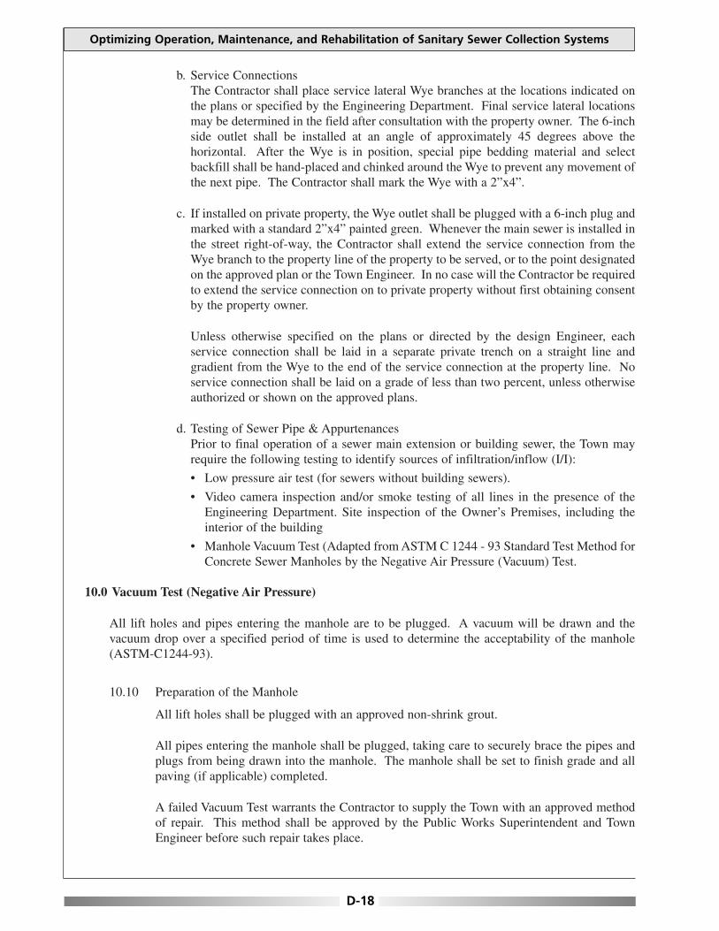
b. Service ConnectionsThe Contractor shall place service lateral Wye branches at the locations indicated onthe plans or specified by the Engineering Department. Final service lateral locationsmay be determined in the field after consultation with the property owner. The 6-inchside outlet shall be installed at an angle of approximately 45 degrees above thehorizontal. After the Wye is in position, special pipe bedding material and selectbackfill shall be hand-placed and chinked around the Wye to prevent any movement ofthe next pipe. The Contractor shall mark the Wye with a 2”x4”.
c. If installed on private property, the Wye outlet shall be plugged with a 6-inch plug andmarked with a standard 2”x4” painted green. Whenever the main sewer is installed inthe street right-of-way, the Contractor shall extend the service connection from theWye branch to the property line of the property to be served, or to the point designatedon the approved plan or the Town Engineer. In no case will the Contractor be requiredto extend the service connection on to private property without first obtaining consentby the property owner.
Unless otherwise specified on the plans or directed by the design Engineer, eachservice connection shall be laid in a separate private trench on a straight line andgradient from the Wye to the end of the service connection at the property line. Noservice connection shall be laid on a grade of less than two percent, unless otherwiseauthorized or shown on the approved plans.
d. Testing of Sewer Pipe & AppurtenancesPrior to final operation of a sewer main extension or building sewer, the Town mayrequire the following testing to identify sources of infiltration/inflow (I/I):
• Low pressure air test (for sewers without building sewers).
• Video camera inspection and/or smoke testing of all lines in the presence of theEngineering Department. Site inspection of the Owner’s Premises, including theinterior of the building
• Manhole Vacuum Test (Adapted from ASTM C 1244 - 93 Standard Test Method forConcrete Sewer Manholes by the Negative Air Pressure (Vacuum) Test.
10.0 Vacuum Test (Negative Air Pressure)
All lift holes and pipes entering the manhole are to be plugged. A vacuum will be drawn and thevacuum drop over a specified period of time is used to determine the acceptability of the manhole(ASTM-C1244-93).
10.10 Preparation of the Manhole
All lift holes shall be plugged with an approved non-shrink grout.
All pipes entering the manhole shall be plugged, taking care to securely brace the pipes andplugs from being drawn into the manhole. The manhole shall be set to finish grade and allpaving (if applicable) completed.
A failed Vacuum Test warrants the Contractor to supply the Town with an approved methodof repair. This method shall be approved by the Public Works Superintendent and TownEngineer before such repair takes place.
Optimizing Operation, Maintenance, and Rehabilitation of Sanitary Sewer Collection Systems
D-18

10.20 Procedure
a. The test head shall be placed at the inside of the top of the frame and the seal inflated inaccordance with the manufacturer’s recommendations.
b. A vacuum of ten (10) inches of mercury shall be drawn, the valve on the vacuum line ofthe test head closed, and the vacuum pump shut off. With the valves closed, the time shallbe measured for the vacuum to drop to nine (9) inches.
c. The manhole shall pass if the time for the vacuum reading to drop from ten (10) inchesof mercury to nine (9) inches meets or exceeds the values indicated by the MassachusettsWater Resource Authority.
11.0 Manhole and Cleanout Construction
11.10 Scope
This item includes the work necessary for the construction of precast manholes andcleanouts, including: concrete; furnishing and placing of the concrete precast sections;eccentric cones, pipe and fittings; cast iron frames and covers; and all appurtenances, in directrelation to the residential sewerage connection.
11.20 Materials
11.21 Concrete
Concrete used in the construction of the manhole base and other structures specified shall beso proportioned and mixed as to meet a 3,000 psi compression test after 28 days.
11.22 Precast Manhole Sections
Precast concrete sections for manholes shall be minimum of 48 inches in interior diameter.Cones shall be eccentric with a wall thickness of a minimum of five (5) inches andreinforcement similar to that of manhole sections. The tops and bottoms of the cones shallbe parallel. Any manhole having a depth greater than nine (9) feet shall have an extendedbase.
11.23 Precast Concrete Bases
Precast base sections or manhole bases shall be approved and inspected by the EngineeringDepartment prior to installation.
11.24 Special Fittings
The wyes, tees, and bends used in the construction of the drop manholes assembly and thecleanouts shall be either PVC or ductile iron. The pipe and fittings shall conform to thespecifications as set forth in these Specifications. Drop manhole assemblies shall be encasedin CDF or as required by the Public Works Superintendent.
11.25 Manhole Frames and Covers
All manhole frames and covers shall be of a size and shape detailed on the plans or approvedequal. The castings shall be tough, close-grained, gray iron, free from blowholes, shrinkageand cold shuts. They shall conform to ASTM A 48 - Class 30 and shall be sound, smooth,clean and free from blisters and all defects. All castings shall be planed and ground where
Appendix D: House Lateral Design Standards
D-19

necessary to ensure perfectly flat and true surfaces. Covers shall be true and shall seat withinthe ring at all points. Manhole covers shall have a maximum of two (2) holes. With the word“SEWER”, cast upon the cover and be American made.
11.26 Manhole Steps
Steps for precast manholes shall be of steel reinforced polypropylene plastic, or approvedequal. All steps shall be in conformance with ASTM C-478 and shall be aligned vertically.All steps within a manhole shall be of the same design, type and size. Mixing of unmatchedsteps within the same manhole is not permitted.
Steps shall be placed where there are no incoming or outgoing lines. Loose steps shall because for rejection of that manhole cone or section.
11.27 Manhole Blockouts / Plugged Boot
Provide manhole blockouts and or plugged boots for sewer extensions as shown on the planor as required by the Engineering Department. The intent of the blockout is to provide ameans by which future sewer lines can be connected to the manhole with a minimum ofinconvenience. The method of construction shall provide a watertight blockout and shall beapproved by the Town Engineer. Construct invert channels to the manhole wall at theblockout in accordance with the invert elevation directed by the design Engineer.
11.28 Manhole Tables
a. All tables in manholes within right-of-ways, paper streets, and easements shall be madeof red brick.
b. Manholes on private property, at the discretion of the contractor may choose to have apiped invert. This shall utilize two 45-degree bends and a straight section no less than 24inches in length. A concrete table shall be poured and shaped so as to provide positivedrainage to the manhole invert, and a cut-out provided in the center section PVC.
11.29 Manhole Inverts
The inverts of the manholes shall be constructed in conformance with the details shown onthe Plans. The manhole inverts shall provide a smooth flow-through characteristic. No sharpedges or rough sections which will tend to obstruct the flow of sewerage will be permitted.All cement mortar used in the construction of the inverts shall be trowelled smooth. Thecontractor may, at his option, use precast bases with prepoured and formed inverts (channels).
11.30 Drop Manholes
Outside Drop manholes shall be constructed as required or at the location shown and asdetailed on the approved plans [See detail 18.20 Appendix A]. The outside drop in its entiretyshall be encased in flowable fill.
12.0 Grinder Pumps and Sewage Ejectors
a. In cases where the existing sewer will not drain by gravity to the sewerage system, a pump systemshall be employed. A pump system shall consist of a precast pump chamber, with a minimumstorage capacity of 1,000 gallons. A 0.5 horsepower grinder style pump and a piped connectionrated for pressure in excess of 150 PSI shall be utilized.
Optimizing Operation, Maintenance, and Rehabilitation of Sanitary Sewer Collection Systems
D-20
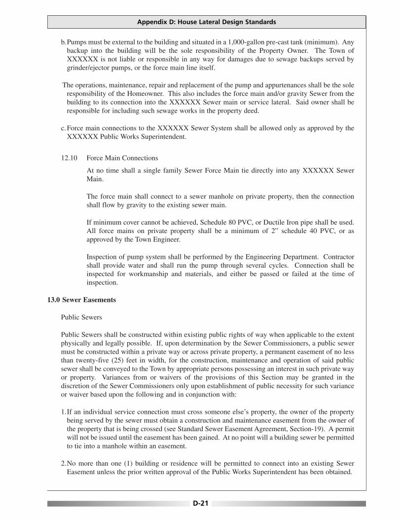
b.Pumps must be external to the building and situated in a 1,000-gallon pre-cast tank (minimum). Anybackup into the building will be the sole responsibility of the Property Owner. The Town ofXXXXXX is not liable or responsible in any way for damages due to sewage backups served bygrinder/ejector pumps, or the force main line itself.
The operations, maintenance, repair and replacement of the pump and appurtenances shall be the soleresponsibility of the Homeowner. This also includes the force main and/or gravity Sewer from thebuilding to its connection into the XXXXXX Sewer main or service lateral. Said owner shall beresponsible for including such sewage works in the property deed.
c.Force main connections to the XXXXXX Sewer System shall be allowed only as approved by theXXXXXX Public Works Superintendent.
12.10 Force Main Connections
At no time shall a single family Sewer Force Main tie directly into any XXXXXX SewerMain.
The force main shall connect to a sewer manhole on private property, then the connectionshall flow by gravity to the existing sewer main.
If minimum cover cannot be achieved, Schedule 80 PVC, or Ductile Iron pipe shall be used.All force mains on private property shall be a minimum of 2” schedule 40 PVC, or asapproved by the Town Engineer.
Inspection of pump system shall be performed by the Engineering Department. Contractorshall provide water and shall run the pump through several cycles. Connection shall beinspected for workmanship and materials, and either be passed or failed at the time ofinspection.
13.0 Sewer Easements
Public Sewers
Public Sewers shall be constructed within existing public rights of way when applicable to the extentphysically and legally possible. If, upon determination by the Sewer Commissioners, a public sewermust be constructed within a private way or across private property, a permanent easement of no lessthan twenty-five (25) feet in width, for the construction, maintenance and operation of said publicsewer shall be conveyed to the Town by appropriate persons possessing an interest in such private wayor property. Variances from or waivers of the provisions of this Section may be granted in thediscretion of the Sewer Commissioners only upon establishment of public necessity for such varianceor waiver based upon the following and in conjunction with:
1.If an individual service connection must cross someone else’s property, the owner of the propertybeing served by the sewer must obtain a construction and maintenance easement from the owner ofthe property that is being crossed (see Standard Sewer Easement Agreement, Section-19). A permitwill not be issued until the easement has been gained. At no point will a building sewer be permittedto tie into a manhole within an easement.
2.No more than one (1) building or residence will be permitted to connect into an existing SewerEasement unless the prior written approval of the Public Works Superintendent has been obtained.
Appendix D: House Lateral Design Standards
D-21

3.All costs for initial installation, subsequent repair, relocation, change or replacement of BuildingSewers shall be at the Owner’s expense.
4.Owner shall not place or permit to be placed any trees or other deep-rooted landscaping directly overor within twelve and one-half (12.5) foot horizontal distance of the Sewer line. Any trees orlandscaping placed within the easements or rights-of-ways are at risk of being damaged or removedby the Town without the obligation of replacement.
5.Owner shall not place or permit to be placed any permanent or temporary structures, mounding,lighting, fencing, signs, retaining/landscaping/entrance walls, irrigation lines, etc. directly over orwithin twelve and one-half (12.5) foot horizontal distance of Building Sewers or any other sewerfacility. Any of the above listed items placed within easements or rights-of-ways are at risk of beingdamaged or removed by the Town without the obligation of replacement.
6.It shall also be the responsibility of the Owner to insure that all manhole and clean-out top ofcastings extend to finish grade and are not buried, sodded over, placed in concrete, or obstructed inany way.
7.The Town may periodically perform field inspections to verify compliance with the above-mentioned requirements. If a violation exists then the Owner must immediately remedy thesituation.
8.Bolted and gasketted sewer manhole covers will be required at all off road locations or anywheredeemed necessary by the Public Works Superintendent.
14.0 Protection of Water Supply
1.There shall be no physical connections between a Building Sewer and the Water Supply System orappurtenances thereto which would permit the passage of any polluted water into the water supplysystem. Sewers shall be laid at least ten (10) feet horizontally from any existing or proposed waterline. The distance shall be measured centerline to centerline. In cases where it is not practical orallowable to maintain a ten (10) foot horizontal separation, the Town may consider the installationof the sewer closer to the water line, provided that:
a.The water line is in a separate trench or on an undisturbed earth shelf located to one side of thesewer.
b.At an elevation so the bottom of the water line is at least eighteen (18) inches above the top of thesewer line.
c.Building Sewers crossing water mains shall be laid to provide a minimum vertical separationdistance of eighteen (18) inches between the outside of the water main and the outside of thesewer. This shall be the case where the water main is either above or below the sewer. Thecrossing shall be arranged so that the sewer joints will be equidistant and as far as possible fromthe water line joints. Where a water line crosses under a sewer, adequate structural support shallbe provided for the sewer to prevent damage to the water line. When it is impossible to obtainproper horizontal and vertical separation as stated above, the building sewer shall be designed andconstructed equal to the specifications required for water pipe, and shall be pressure tested toassure water tightness prior to backfilling.
Optimizing Operation, Maintenance, and Rehabilitation of Sanitary Sewer Collection Systems
D-22

14.10 Well Areas-Zone II
Any Sewers within one thousand (1,000) feet of a Public Water Supply or fifty (50) feet of adomestic well, shall be of watertight construction. At a minimum, schedule 40 PVC pipewith solvent weld joints is to be used.
For all parts of new sewer connections within a designated Zone II, only hard connectionswill be allowed. No fernco or flexible rubber connections shall be permissible, unlessapproved by the XXXXXX Engineering Department.
15.0 Pipe Jacking & Directional Drilling
15.10 Pipe Jacking
A specialized tunneling method for installing underground pipelines with minimal surfacedisruption. Primarily used for new sewer construction, it is also used for sewer replacementand relining.
15.20 Horizontal Directional Drilling
Horizontal Directional Drilling (HDD) is a trenchless method for installing any number ofutilities. It is a multi-stage process consisting of site preparation, and restoration, equipmentsetup, and drilling a pilot bore along a predetermined path and then pulling the product backthrough the drilled space. Alignment of the bore is accomplished by a hydraulic jack as thedrill bit head is pushed into the ground. The orientation and tracking of the head isdetermined by an above ground radio detection device, which picks up radio signalsgenerated from a transmitter on the drill itself.
Contractor is responsible for selecting or designing drilling fluids for the site specific soil andgroundwater conditions. Confine free flowing (escaping) slurry or drilling fluids at theground surface during pull-back or drilling. This can be accomplished by creating sumpareas or vacuum operations to prevent damage or hazardous conditions in surrounding areas.
Any proposed pipe-jacking or directional drilling must be submitted by a registeredProfessional Engineer in the Commonwealth of Massachusetts, and be approved by theXXXXXX Engineering Department.
15.25 Boring Path Report
Furnish a Bore Path Report to the Engineering Department within seven (7) days of thecompletion of each bore path. Include the following in the report:
1. Location of project including the Permit Number and when assigned.
2. Name of person collecting the data, including title, position and company name.
3. Investigation site location.
4. Identification of the detection method used.
5. Elevations and offset dimensions as required.
15.30 Vacuum Holes
In preparation of pipe-jacking activities, an as-built showing any and all existing utilities in
Appendix D: House Lateral Design Standards
D-23
the area of work must be verified by the vacuum hole method. These field locations must besubmitted in lieu of any proposed sewer work.
16.0 Validity
All regulations or parts of regulations in conflict herewith are hereby repealed.
The invalidity of any section, clause, sentence or provision of these regulations shall not affect thevalidity of any other part of these Regulations, which can be given effect without such invalid partor parts.
These Sewer Regulations shall not contravene, nor render ineffective any of the lawfullyestablished rules and regulations of the Massachusetts Water Resources Authority.
Optimizing Operation, Maintenance, and Rehabilitation of Sanitary Sewer Collection Systems
D-24
This appendix contains information developed by EPA Region IV for evaluating Management,Operation, and Maintenance (MOM) programs for collection systems within the region. The checklistcan be used to evaluate collection system operation and maintenance programs and to highlightprogram areas needing improvement.
Appendix E: EPA Region 4 MOM Checklist
E-1
APPENDIX EEPA REGION 4 MOM CHECKLIST

This page is intentionally blank.
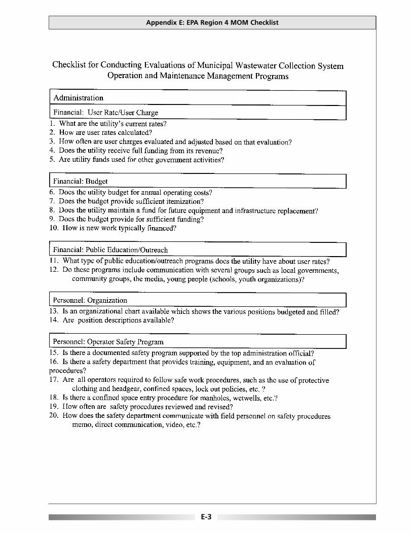
Appendix E: EPA Region 4 MOM Checklist
E-3
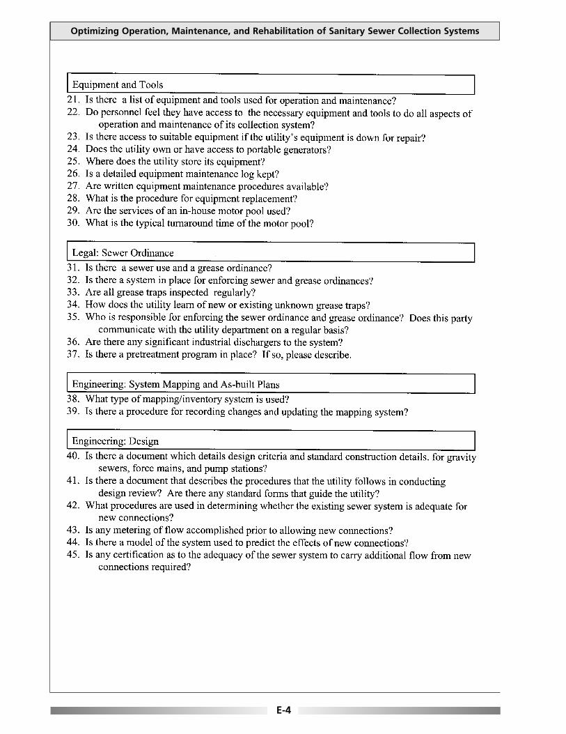
Optimizing Operation, Maintenance, and Rehabilitation of Sanitary Sewer Collection Systems
E-4

Appendix E: EPA Region 4 MOM Checklist
E-5

Optimizing Operation, Maintenance, and Rehabilitation of Sanitary Sewer Collection Systems
E-6

Appendix E: EPA Region 4 MOM Checklist
E-7
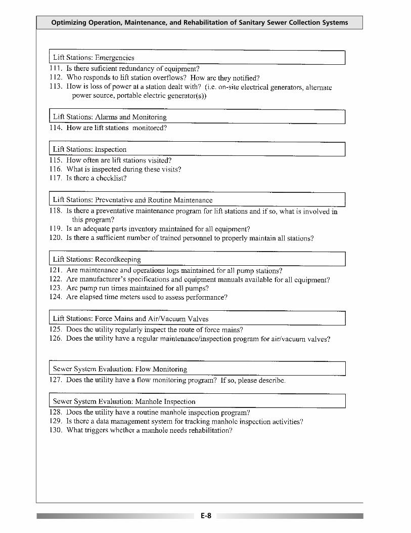
Optimizing Operation, Maintenance, and Rehabilitation of Sanitary Sewer Collection Systems
E-8

Appendix E: EPA Region 4 MOM Checklist
E-9

This page is intentionally blank.
This appendix contains examples of various inspection forms obtained from the MassachusettsWater Resources Authority (MWRA), the Boston Water and Sewer Commission (BWSC), and theMonroe County Department of Environmental Services (MCDES) in New York. These inspectionforms can be adapted to fit specific collection system needs. They are not presented as inclusive of allsituations or circumstances.
Appendix F: Inspection Forms
F-1
APPENDIX FINSPECTION FORMS
BWSC – TV Request Form F-3
BWSC – Manhole Inspection Report F-4
MWRA – Hydraulic Structure Inspection Report F-5
MWRA – Manhole Inspection Report F-6
MWRA – Roving Crew Facility Checklist (Alewife Brook Station) F-7
MCDES – Pump Station Standard Operation Inspection List F-8
MCDES – Tunnel Facility Standard Operation Inspection List F-9
MCDES – TV Inspection Sheet F-10

This page is intentionally blank.

Appendix F: Inspection Forms
F-3
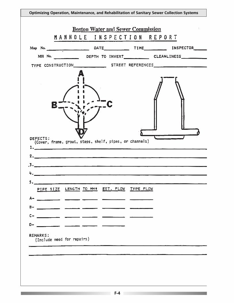
Optimizing Operation, Maintenance, and Rehabilitation of Sanitary Sewer Collection Systems
F-4

Appendix F: Inspection Forms
F-5

Optimizing Operation, Maintenance, and Rehabilitation of Sanitary Sewer Collection Systems
F-6
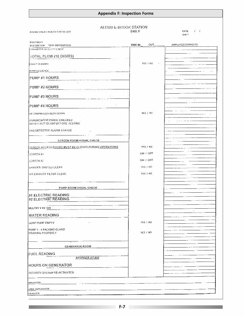
Appendix F: Inspection Forms
F-7

Optimizing Operation, Maintenance, and Rehabilitation of Sanitary Sewer Collection Systems
F-8
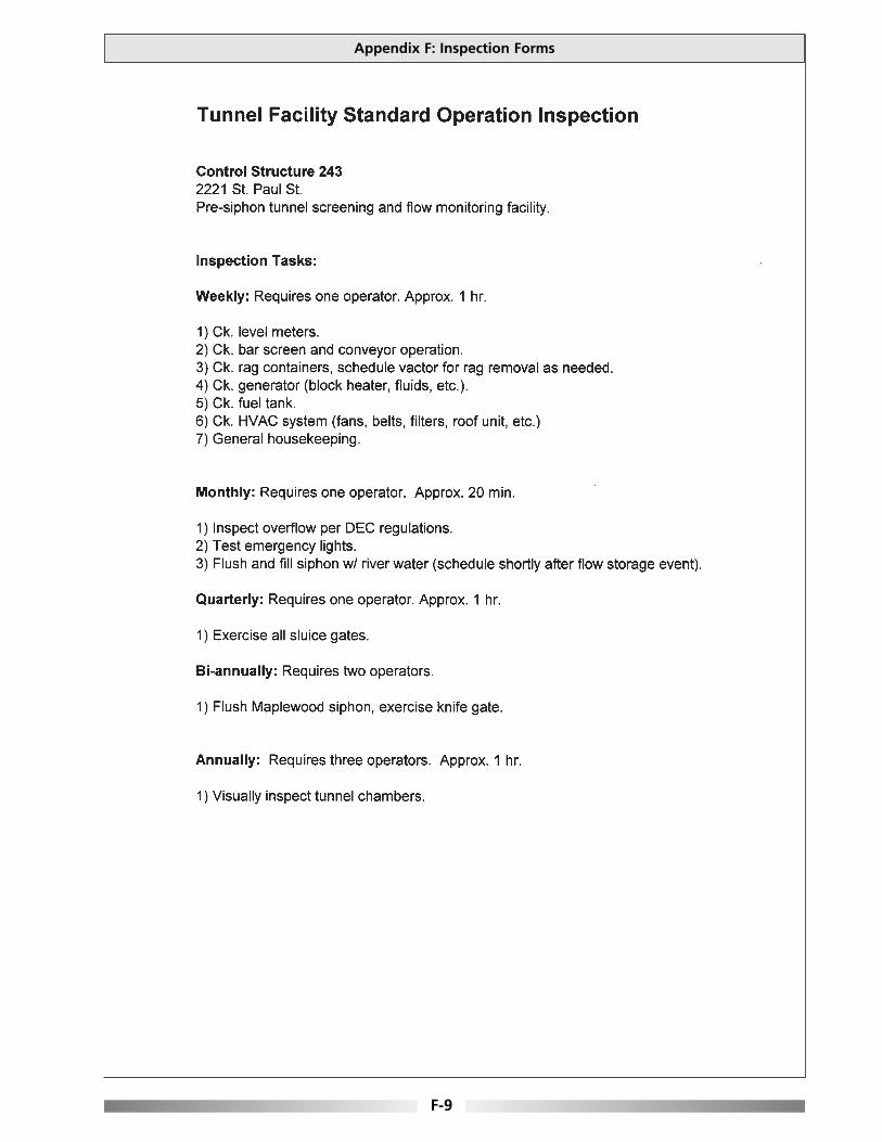
Appendix F: Inspection Forms
F-9
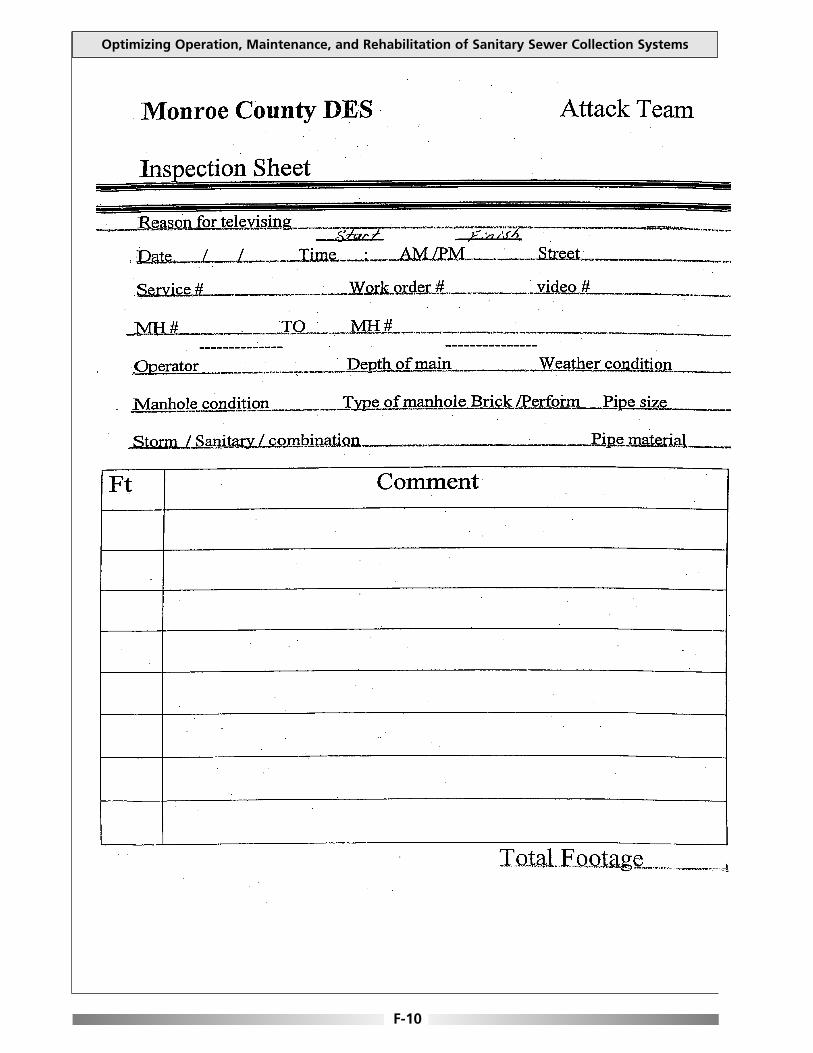
Optimizing Operation, Maintenance, and Rehabilitation of Sanitary Sewer Collection Systems
F-10

We Value Your Feedback
Please notify us if you discover mistakes or omissions in this document. Submissions can be sentelectronically, mailed or faxed to:
New England Interstate Water Pollution Control CommissionATTN: Collection System Guidance
Boott Mills South100 Foot of John Street
Lowell, MA 01852Tel: 978/323-7929Fax: 978/[email protected]
Brief description of error or omission:
____________________________________________________________________________________
____________________________________________________________________________________
____________________________________________________________________________________
____________________________________________________________________________________
Suggested improvement:
____________________________________________________________________________________
____________________________________________________________________________________
____________________________________________________________________________________
____________________________________________________________________________________
General comments:
____________________________________________________________________________________
____________________________________________________________________________________
____________________________________________________________________________________
____________________________________________________________________________________
Can we contact you for additional information? If so please provide contact information:
____________________________________________________________________________________
____________________________________________________________________________________
____________________________________________________________________________________
Thank You.
Optimizing Operation, Maintenance, and Rehabilitation of Sanitary Sewer Collection Systems