new facility of resonance project: two pairs of...
TRANSCRIPT

Second GDRE "Cosmophysic" Workshop,
Touluose, 2009
New facility of RESONANCE
project: two pairs of satellites
for multiscale studies
M. M. Mogilevsky

Second GDRE "Cosmophysic" Workshop,
Touluose, 2009
Main scientific goals of RESONANCE project
1. Nearequatorial region
- Dynamics of cyclotron maser in magnetospheres,
- Ring current formation,
- Refilling of plasmosphere after magnetic storms.
2. Auroral region
- Global phenomena in auroral region (AKR source and propagation, VLF/ELF /ULF generation),
- The role of the small-scale phenomena in the
global plasma dynamics (acceleration region).
3. Joint experiment with ground-based heating facility

Second GDRE "Cosmophysic" Workshop,
Touluose, 2009
Sketch of measurement in the
selected flux tube
RESONANCE 2
orbit
RESONANCE 1
orbit
Initial version of RESONANCE project
Two satellites will be
launched on magneto-
synchronous orbits for
long-term
measurements in the
inner magnetosphere in
the selected magnetic
flux tube. Selected flux
tube will be conjugate
to the ionosphere above
the HAARP heating
facility (Gakona,
Alaska).

Second GDRE "Cosmophysic" Workshop,
Touluose, 2009
The launcher “Soyuz” 2B with “Fregat” is enable to launch satellites at two magneto-synchronous orbits
Orbit parameters are following:
T = 8 h
hap = 28 000 km
hper = 500 km
i = +/- 63,4°

Second GDRE "Cosmophysic" Workshop,
Touluose, 2009
Background for RESONANCE project transformation
From the results of CLUSTER measurements was found that the most of
chorus element are very similar but some of them has significant difference –
arriving time and frequency range. This result can’t be explained in the frame
of well-known physical mechanisms.
Spectrograms of chorus type emissions detected onboard of two satellites
CLUSTER. Perpendicular to the magnetic field component of the distance
between satellites was 43 km.
Correlations coefficient of chorus
elements as a function of the distance
between satellites.
(From O.Santolik et al. 2007)

Microwave Amplification by StimulatedEmission of Radiation
pumping
n2
n1
W1 W2
Energy
Popula
tion
inver
sion
Active substance: gas, crystal, semiconductor
Electrodynamics system: crystal, mirrors
Operating modes: = W2 – W1
Population inversion:pumping;
~ n2 – n1
k

Composition of magnetosphere cyclotron mazer
Electrodynamical system:
magnetic flux tube filled with cold
plasma;
Conjugate ionospheres as mirrors
Loss cone
Wave packet
Ionosphere Operating modes:
whistler
and ion-cyclotron waves
< H (e,p)
Active substance: energetic
electrons (We > 5 keV ),
protons (Wp > 10 keV )

«Shock» wave in phase space
One-dimensional relaxation
of beams in plasmas:• Ivanov and Rudakov (1966);
• Ivanov (1977)
Quasilinear relaxation of the cyclotron instability
in an inhomogeneous magnetic field
F
HD ~
n1/2
kin ~ n
V||
F Flatitude=30o
equator

“Backward” oscillator in magnetosphere
R=0 R=0electrons waves
l ~ 1000 km << RE
Absolute instability threshold
(BWO regime):l
q/2Generation
of ELF noiseQuasiperiodic
generation
Stochastic
generation

Discrete emissions in magnetospheric maser: whistler mode
0 time, s 10
Fre
quen
cy, kH
zELF/VLF chorus emissions (0.2–10 kHz)2
Close relation of chorus with noiselike (hiss) emissions
Repetition period (~0,2 s) smaller than the bounce period (0,5–1 s)
Large growth rate and fast frequency drift
Features of self-organized criticality

Second GDRE "Cosmophysic" Workshop,
Touluose, 2009
Strategy of measurements: two PAIRS of satellites will be
launched on the same orbits. The distance between
satellites of one pair can be controlled by TC.
RESONANCE 2А и 2В
RESONANCE 1А и 1В
~ 1-10 km
~1- 5 • 103 km
~ 5-15 • 103 km

Second GDRE "Cosmophysic" Workshop,
Touluose, 2009
New capability of RESONANCE project:
multiscale study of Auroral Region
Sketch of phenomena in auroral region. Satellites will cross all
principal areas (red line – projection of RESONANCE orbit).

Second GDRE "Cosmophysic" Workshop,
Touluose, 2009
New capability of RESONANCE project:
two paradigms of acceleration region (1)
W1
W2
W2 = W1 + φφ
Magnetic field aligned DC electric field

Second GDRE "Cosmophysic" Workshop,
Touluose, 2009
New capability of RESONANCE project:
two paradigms of acceleration region (2)
W1
W2
φiW2 = W1 + φ
φ = Σ φi
1 ms
To study acceleration region: one satellite will be inside of acceleration
region, another one – outside of it. Result of acceleration will be
detected from comparative analysis data from two satellites.
Electrodynamics structure measured onboard of
INTERBALL-2 satellite.
“Deformed” distribution function of electrons
measured onboard FAST satellite.

Scientific equipment (1)EM field and waves measurements
Flux-gate magnetometer 3 components of B field, DC – 10 Hz
ULF electric field receiver 3 components of E field, DC – 10 Hz
VLF receiver 3 electric and 3 magnetic
components of EM field, 10 Hz – 20
kHz
HF receiver 3 electric and 3 magnetic
components of EM field, 5kHz – 10
MHz
Mutual impedance probe 10 kHz – 10 MHz
Space radio interferometer 5-10 MHzSecond GDRE "Cosmophysic" Workshop,
Touluose, 2009

Scientific equipment (2)Plasma and particles measurements
Cold plasma measurements 0 – 20 eV
Suprathermal plasma measurements –
3D electrons
10 eV – 15 keV
Suprathermal plasma measurements –
3D ions and composition
10 eV – 15 keV
Fast electrons analyzer 5 keV – 50 keV
Energetic particles analyzer 10 keV – 100 keV
Ring current particles measurements 20 keV – 1 MeV
Measurements of radiation belts particles 100 keV – 10 MeV
Second GDRE "Cosmophysic" Workshop,
Touluose, 2009

Second GDRE "Cosmophysic" Workshop,
Touluose, 2009
MKA – new possibility for multiscale study

Second GDRE "Cosmophysic" Workshop,
Touluose, 2009
Orbits
Strategy of Scientific measurements
- near equatorial region
- auroral region
Second GDRE "Cosmophysic" Workshop,
Touluose, 2009
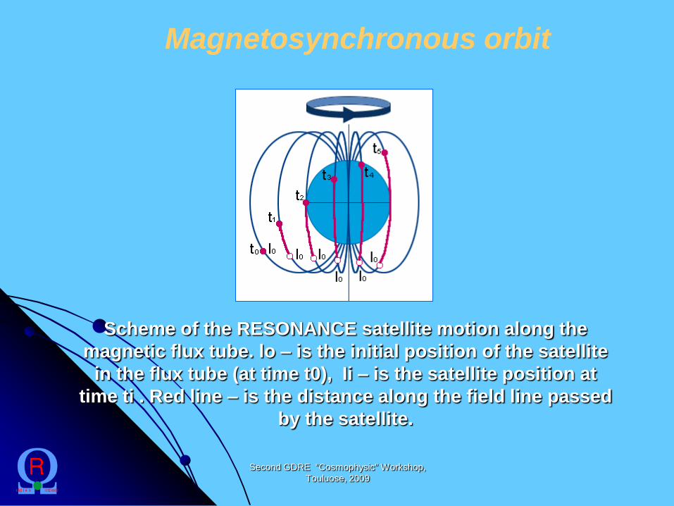
Magnetosynchronous orbit
Scheme of the RESONANCE satellite motion along the
magnetic flux tube. lo – is the initial position of the satellite
in the flux tube (at time t0), Ii – is the satellite position at
time ti . Red line – is the distance along the field line passed
by the satellite.

Second GDRE "Cosmophysic" Workshop,
Touluose, 2009
Two pairs of satellites will be launched in the magneto-synchronous orbit.
Orbit parameters are following:
T = 8 h
hap = 28 000 km
hper = 500 km
i = +/- 63,4°

Second GDRE "Cosmophysic" Workshop,
Touluose, 2009
Scheme of the launch
RESONANCE project

Second GDRE "Cosmophysic" Workshop,
Touluose, 2009
Strategy of meagurements (1)

Second GDRE "Cosmophysic" Workshop,
Touluose, 2009
Blue curve – inner and outer
boundaries of the flux tube.
Red curve – orbit of R1 satellite
(solid line – in the flux tube,
dashed line – outside the flux
tube).
Green curve – orbit of R2 satellite.
Symbols t1 and t2 mark
synchronous entering and leaving
the flux tube by the satellites R1
and R2.
Strategy of meagurements (1)
Location of satellites in the selected flux tube

Second GDRE "Cosmophysic" Workshop,
Touluose, 2009
Strategy of meagurements (2)

Second GDRE "Cosmophysic" Workshop,
Touluose, 2009
Strategy of measurements (2)

Second GDRE "Cosmophysic" Workshop,
Touluose, 2009
Strategy of measurements (2)
12:00 MLT
24:00 MLT
R2
R1
MLT1 = MLT2
1

Second GDRE "Cosmophysic" Workshop,
Touluose, 2009
Strategy of meagurements (3)

Second GDRE "Cosmophysic" Workshop,
Touluose, 2009
Strategy of measurements (3)

Second GDRE "Cosmophysic" Workshop,
Touluose, 2009
12:00 MLT
24:00 MLT
R2
R1
L1 = L2
2
Strategy of meagurements (3)

Second GDRE "Cosmophysic" Workshop,
Touluose, 2009
RESONANCE satellite
Flight position of satellite
(from sun direction) (anti-sun direction)

Second GDRE "Cosmophysic" Workshop,
Touluose, 2009
Scheme of the launch
Launcher – “Soyuz” 2B with “Fregat”
First stage – launch to the
intermediate orbit and formation
orbit for the first pair of
satellites
Second stage - formation
orbit for the second pair of
satellites

Second GDRE "Cosmophysic" Workshop,
Touluose, 2009
Accuracy of stabilization- 4 ×10⁻³ deg/с
Accuracy of orientation - better then 1 deg
Onboard timing accuracy – 0.1 microsecond
Operation on flight - not less then 3 yearsт
Onboard memory - 6 Gbyte (auxiliary)
TM bit rate - 3 - 30 Mbit per second
Capacity of TM, transmitted during one day - not less then 6 Gbyte
Band of TM transmitter - S (X)
Total mass ~ 200 kg
Mass of scientific payload ~ 50 kg
Technical Capability of MKA sattelite

Second GDRE "Cosmophysic" Workshop,
Touluose, 2009
NEW version of RESONANCE project
Preliminary program of satellite separation
First pair (1A/1B) Second pair (2A/2B)
1 phase (6-9
months after the
launch)
1-10 km 1-10 km
2 phase (9-18
months after the
launch)
1-10 km 10-100 km
3 phase (18-27
months after the
launch)
10-100 km 100-1000 km
4 phase (27-36
months after the
launch)
100-1000 km 1000-9600 km

Second GDRE "Cosmophysic" Workshop,
Touluose, 2009
New elements of RESONANCE
project
Intersatellite density and fluctuation of
density measurements (RIK experiment)
More possibility for manoeuvre along the
orbit
Onboard wave analysis from HF and VLF
frequency range.

Second GDRE "Cosmophysic" Workshop,
Touluose, 2009
Schedule of RESONANCE project
2009 – documentation design
2010 – development and delivery of technological model
2011 – input, autonomous and integrating tests of technological model
in IKI and factory (NPOL)
2011-2012- development and delivery of flight models
2013 – input, autonomous and integrating tests of flight models
2014– launch
2014-2018 – operation in flight

Second GDRE "Cosmophysic" Workshop,
Touluose, 2009
Magn. Injection
ELF/VLF WAVE GENERATIONRESONANCE-HAARP
JOINT EXPERIMENT

Second GDRE "Cosmophysic" Workshop,
Touluose, 2009
30.6 acres
Antenna of HAARP heating facility

Second GDRE "Cosmophysic" Workshop,
Touluose, 2009
• 180 Element (12x15) Phased Array
• 360 Nested Crossed Dipoles
• Low Band Dipole - 2.8 to 8.4 MHz
• High Band Dipole - 7to 10 MHz
• 3.6 MW Radiated from 360 10 kW Transmitters
• Instantaneous Bandwidth
• 200 kHz (2.8 MHZ)
• 500 kHz (10 MHz)
• Beam can be Slued 30° off Zenith in any
Azimuth 2.8 to 8 MHz (15° at 10 MHz)
• Rapid Scanning of +/- 15°
• FM, AM and Pulse Modulation to 30 kHz
• Dual Frequency Operation (Split Array)
• Linear, Left and Right Circular Polarization
Beam width
20°x16° (2.8 MHz)
5.7°x4.5° (10 MHz)
HAARP capability

Second GDRE "Cosmophysic" Workshop,
Touluose, 2009
RESEARCH TOPICS
ULF/ELF/VLF generation by current modulation
Magnetospheric Injection - Artificially Stimulated Emissions
(ASE)
ULF Magnetosonic F/Region generation and
Injection to the Alfvenic Waveguide - Triggered Pc1
Langmuir turbulence - Parametric Instabilities
Magnetospheric duct generation and wave injection
Field aligned striations - Scintillations
Upper hybrid waves and conversion of lower hybrid
waves to whistlers

RESONANCE-HAARP JOINT EXPERIMENT
The main goal of joint experiment – quantitative data of
ionosphere-magnetosphere coupling with a good time
resolution:
- Artificial excitation and/or stimulation of wave modes;
- Modification of the flux of precipitating particles;
- Variation of maser Q-factor by the modification of reflection index in
the ionospheric footprint of the selected magnetic flux tube.
Second GDRE "Cosmophysic" Workshop,
Touluose, 2009
Artificial feedback formation
1 – Earth, 2 – ionosphere, 3 – heated ionospheric
region, 4 – magnetic flux tube, 5 – TM line, 6 –
satellite, 7 – trajectories of particles and ducted
waves