new generation incinerators atlas containerizedmesse.no/exhibitordocuments/95716/2735/new...
TRANSCRIPT
For further information contact us or our representative:
Atlas ContainerizedIncinerators10’ & 20’ ISO containers
Standard Equipment:IncineratorOil Sludge TankDiesel Oil TankLighting SystemCO2 Fire Fighting EquipmentVentilation Chimney External Emergency Switch
Plus external hook up forelectric power and all pipeconnections
Atlas Skid MountedIncinerators
Standard Equipment:IncineratorSludge Oil TankDiesel Oil Tank
Plus all pipelines, electriccables, and necessary components mounted on a common base
CT
Vor
ding
borg
A/S
55
37 0
0 09
No.
01E
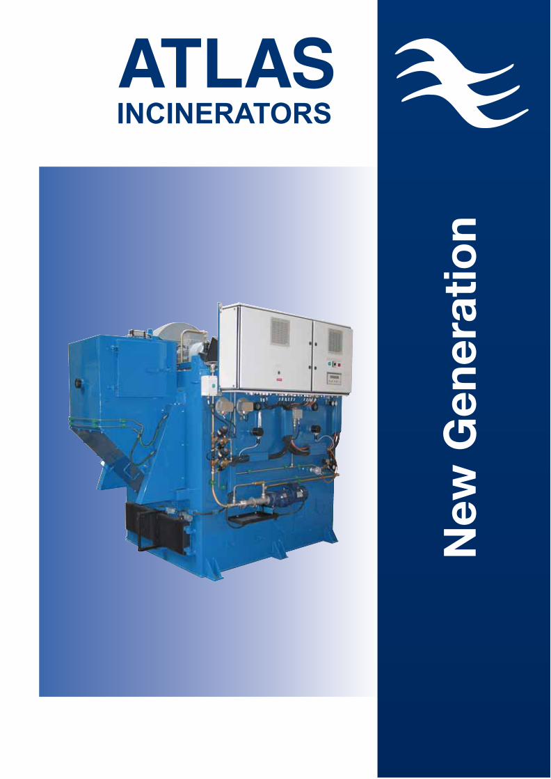
New
Gen
erat
ion
INCINERATORS
Atlas Incinerators A/SP.O. Box 143 Masnedoevej 73DK - 4760 VordingborgDenmarkPhone +45 55 34 66 55 Fax +45 55 37 66 [email protected]
Agent:
INCINERATORS
Certificates:
Atlas Incinerators have been examined and tested inaccordance with IMO’s Resolution MEPC. 76 (40) adapted on September 25, 1997 - Tested according to standard specification for shipboard incinerators - adapted on September 26, 1997 - and in accordance to the Guidelines for the Implementation of Annex V of MARPOL 73/78, as well as fulfilling MARPOL Annex VI.
MED Type Approval Certificate
USCG Certificate
Type Approval from the leading Classification Societies.
APPROVAL ATLAS INCINERATORS
New Generation
Agent Representation in:
AlgeriaArgentinaAustraliaBaltic StatesBrazilCanadaChileChinaColumbia/VenezuelaCroatiaFinland FranceGermanyGreeceHollandIcelandIndiaIndonesiaItalyKoreaNorwayMalaysiaMonacoMoroccoPhilippinesPolandPortugalRomaniaRussiaSingaporeSpainTaiwanThailandTunesiaTurkeyUkraineUnited KingdomUnited Arab EmiratsUSAVietnam
INCINERATORS
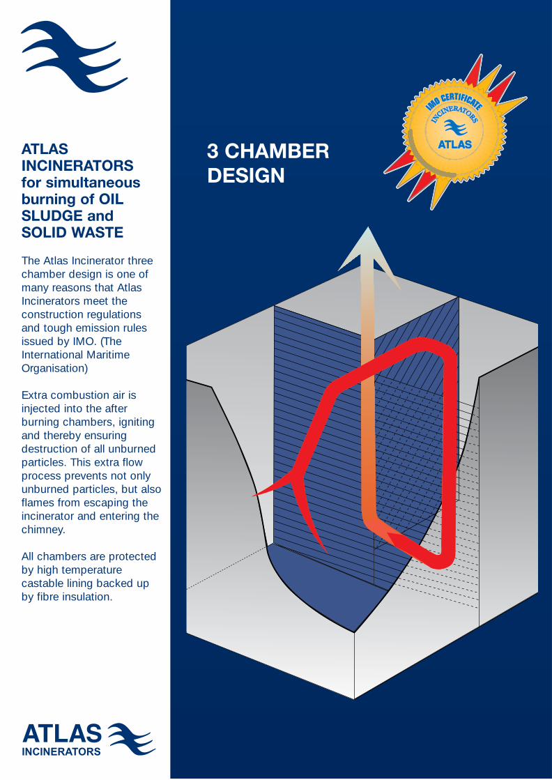
ATLASINCINERATORS for simultaneous burning of OILSLUDGE andSOLID WASTE
The Atlas Incinerator threechamber design is one ofmany reasons that AtlasIncinerators meet the construction regulations and tough emission rulesissued by IMO. (TheInternational MaritimeOrganisation)
Extra combustion air is injected into the after burning chambers, ignitingand thereby ensuring destruction of all unburnedparticles. This extra flow process prevents not onlyunburned particles, but alsoflames from escaping the incinerator and entering thechimney.
All chambers are protected by high temperature castable lining backed up by fibre insulation.
3 CHAMBER DESIGN
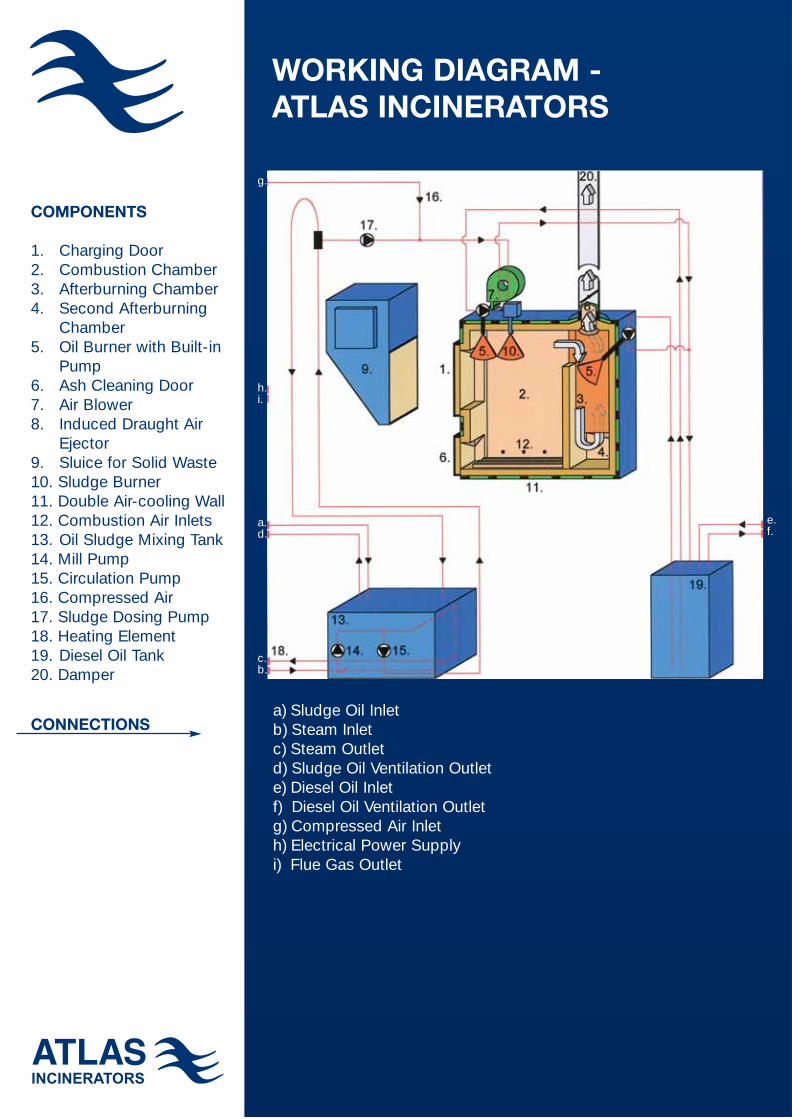
COMPONENTS
1. Charging Door2. Combustion Chamber3. Afterburning Chamber4. Second Afterburning
Chamber5. Oil Burner with Built-in
Pump6. Ash Cleaning Door7. Air Blower8. Induced Draught Air
Ejector9. Sluice for Solid Waste10. Sludge Burner11. Double Air-cooling Wall12. Combustion Air Inlets13. Oil Sludge Mixing Tank14. Mill Pump15. Circulation Pump16. Compressed Air17. Sludge Dosing Pump18. Heating Element19. Diesel Oil Tank20. Damper
CONNECTIONS
WORKING DIAGRAM - ATLAS INCINERATORS
a) Sludge Oil Inletb) Steam Inletc) Steam Outletd) Sludge Oil Ventilation Outlete) Diesel Oil Inletf) Diesel Oil Ventilation Outletg) Compressed Air Inleth) Electrical Power Supplyi) Flue Gas Outlet
INCINERATORS INCINERATORS
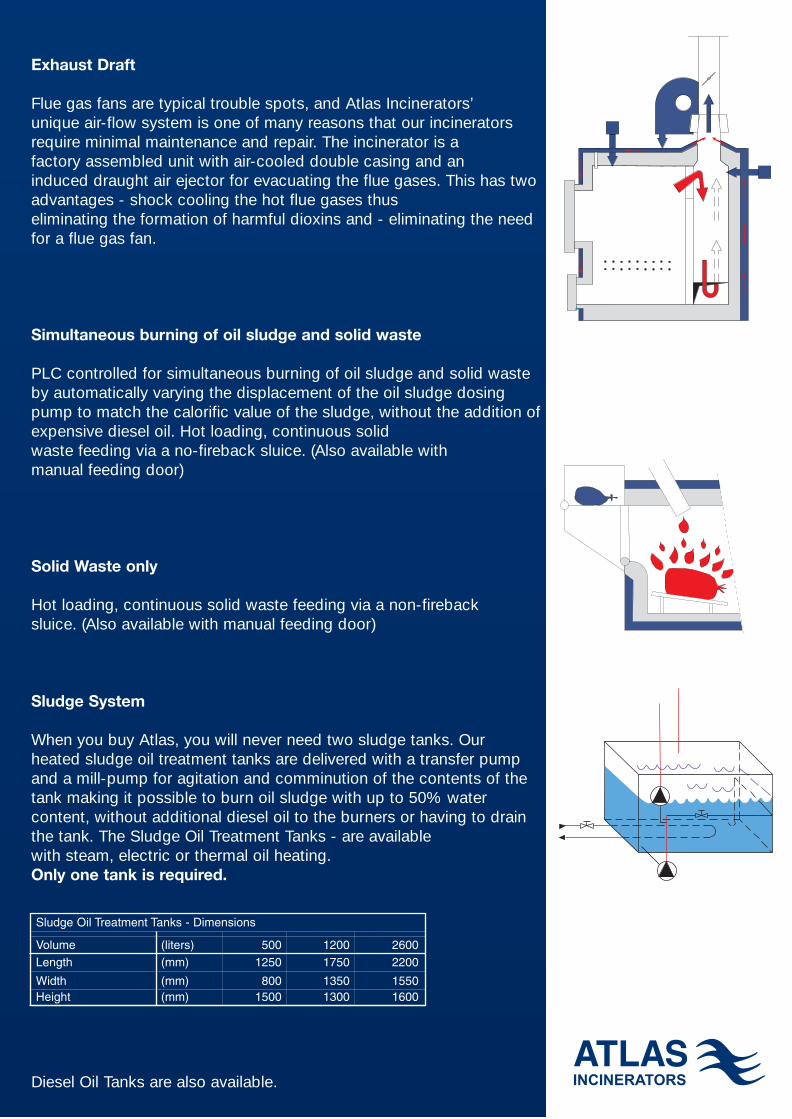
Exhaust Draft
Flue gas fans are typical trouble spots, and Atlas Incinerators’ unique air-flow system is one of many reasons that our incinerators require minimal maintenance and repair. The incinerator is a factory assembled unit with air-cooled double casing and an induced draught air ejector for evacuating the flue gases. This has twoadvantages - shock cooling the hot flue gases thus eliminating the formation of harmful dioxins and - eliminating the needfor a flue gas fan.
Simultaneous burning of oil sludge and solid waste
PLC controlled for simultaneous burning of oil sludge and solid wasteby automatically varying the displacement of the oil sludge dosingpump to match the calorific value of the sludge, without the addition ofexpensive diesel oil. Hot loading, continuous solid waste feeding via a no-fireback sluice. (Also available with manual feeding door)
Solid Waste only
Hot loading, continuous solid waste feeding via a non-fireback sluice. (Also available with manual feeding door)
Sludge System
When you buy Atlas, you will never need two sludge tanks. Our heated sludge oil treatment tanks are delivered with a transfer pumpand a mill-pump for agitation and comminution of the contents of thetank making it possible to burn oil sludge with up to 50% water content, without additional diesel oil to the burners or having to drainthe tank. The Sludge Oil Treatment Tanks - are available with steam, electric or thermal oil heating. Only one tank is required.
Diesel Oil Tanks are also available.
Sludge Oil Treatment Tanks - Dimensions
Volume (liters) 500 1200 2600Length (mm) 1250 1750 2200
Width (mm) 800 1350 1550Height (mm) 1500 1300 1600
g.
a.d.
e.f.
c.b.
h.i.
WL
H
L 1
L2
H2
W2
L 1
L (no sluice)W (no sluice)
W
H
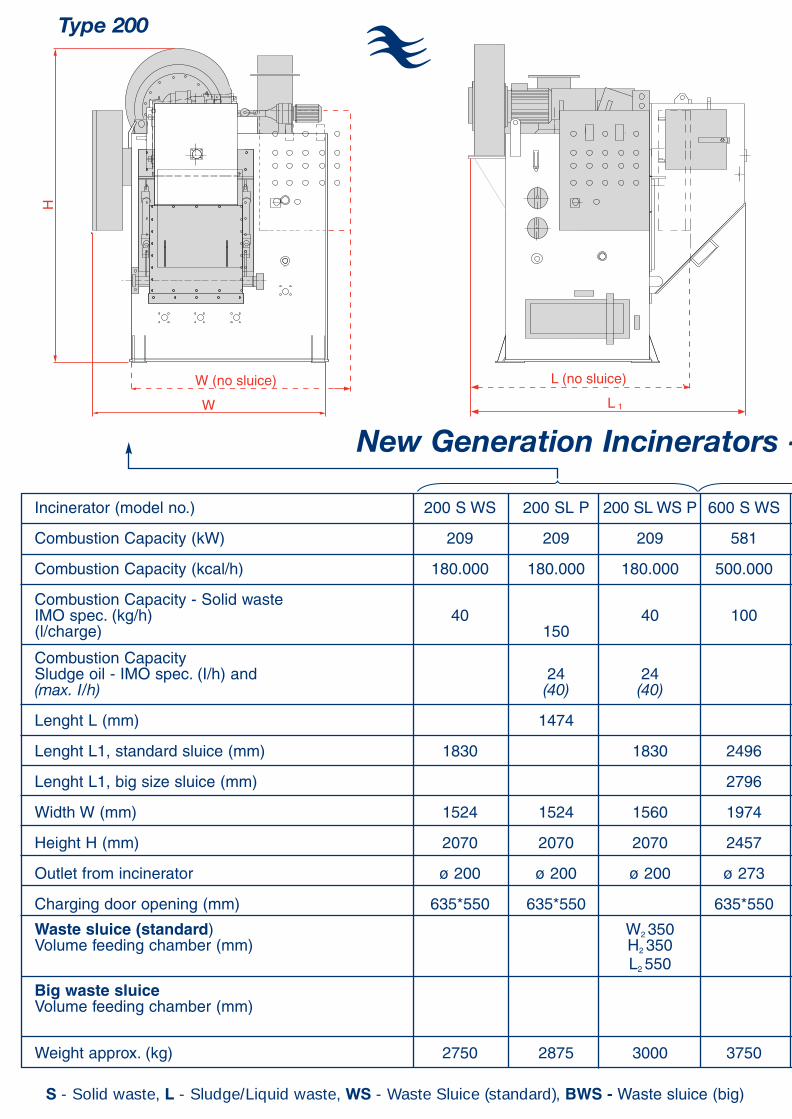
Incinerator (model no.) 200 S WS 200 SL P 200 SL WS P 600 S WS 600 SL P 600 SL WS P 800 S WS 800 SL P 800 SL WS P 1200 S WS 1200 SL M 1200 SL WS M
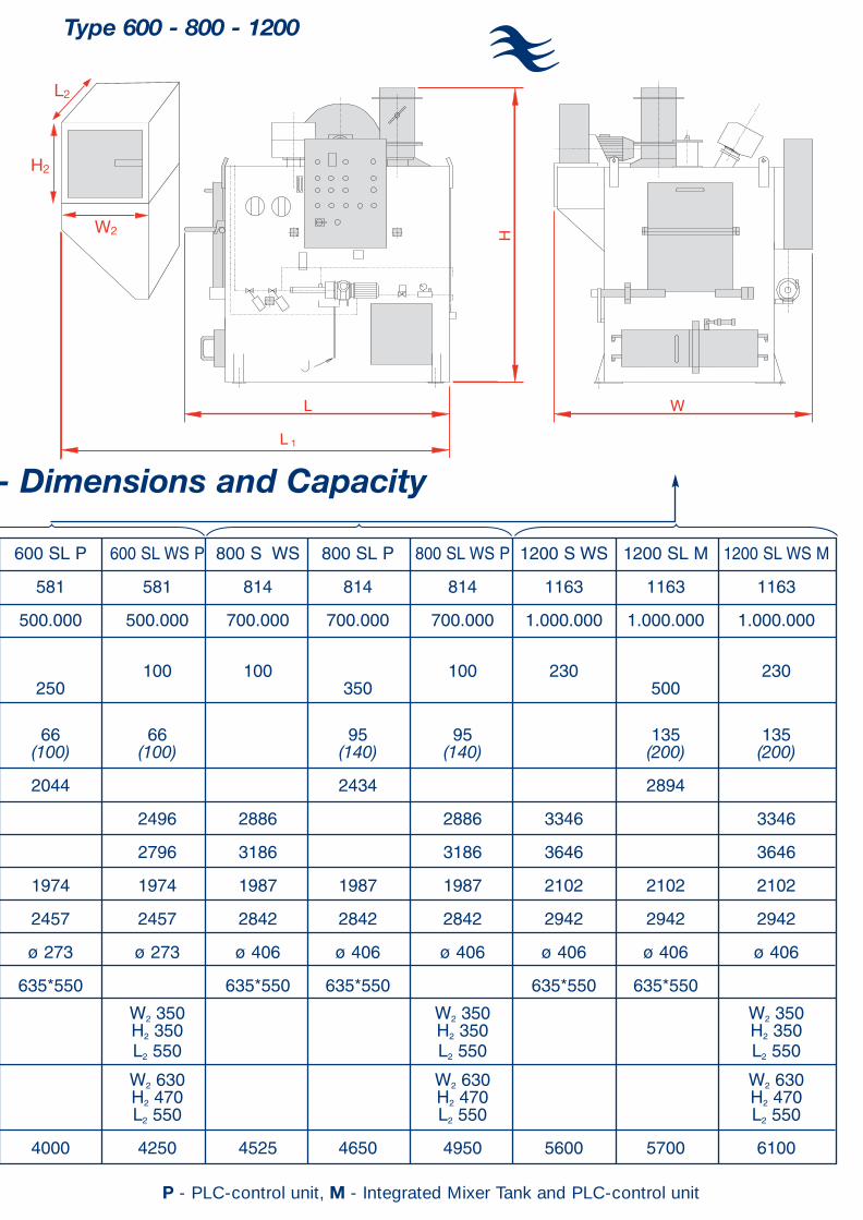
Combustion Capacity (kW) 209 209 209 581 581 581 814 814 814 1163 1163 1163
Combustion Capacity (kcal/h) 180.000 180.000 180.000 500.000 500.000 500.000 700.000 700.000 700.000 1.000.000 1.000.000 1.000.000
Combustion Capacity - Solid wasteIMO spec. (kg/h) 40 40 100 100 100 100 230 230(l/charge) 150 250 350 500
Combustion CapacitySludge oil - IMO spec. (I/h) and 24 24 66 66 95 95 135 135(max. I/h) (40) (40) (100) (100) (140) (140) (200) (200)
Lenght L (mm) 1474 2044 2434 2894
Lenght L1, standard sluice (mm) 1830 1830 2496 2496 2886 2886 3346 3346
Lenght L1, big size sluice (mm) 2796 2796 3186 3186 3646 3646
Width W (mm) 1524 1524 1560 1974 1974 1974 1987 1987 1987 2102 2102 2102
Height H (mm) 2070 2070 2070 2457 2457 2457 2842 2842 2842 2942 2942 2942
Outlet from incinerator ø 200 ø 200 ø 200 ø 273 ø 273 ø 273 ø 406 ø 406 ø 406 ø 406 ø 406 ø 406
Charging door opening (mm) 635*550 635*550 635*550 635*550 635*550 635*550 635*550 635*550
Waste sluice (standard) W2 350 W2 350 W2 350 W2 350Volume feeding chamber (mm) H2 350 H2 350 H2 350 H2 350
L2 550 L2 550 L2 550 L2 550
Big waste sluice W2 630 W2 630 W2 630Volume feeding chamber (mm) H2 470 H2 470 H2 470
L2 550 L2 550 L2 550
Weight approx. (kg) 2750 2875 3000 3750 4000 4250 4525 4650 4950 5600 5700 6100
P - PLC-control unit, M - Integrated Mixer Tank and PLC-control unitS - Solid waste, L - Sludge/Liquid waste, WS - Waste Sluice (standard), BWS - Waste sluice (big)
New Generation Incinerators - Dimensions and Capacity
Type 200 Type 600 - 800 - 1200
WL
H
L 1
L2
H2
W2
L 1
L (no sluice)W (no sluice)
W
H
Incinerator (model no.) 200 S WS 200 SL P 200 SL WS P 600 S WS 600 SL P 600 SL WS P 800 S WS 800 SL P 800 SL WS P 1200 S WS 1200 SL M 1200 SL WS M
Combustion Capacity (kW) 209 209 209 581 581 581 814 814 814 1163 1163 1163
Combustion Capacity (kcal/h) 180.000 180.000 180.000 500.000 500.000 500.000 700.000 700.000 700.000 1.000.000 1.000.000 1.000.000
Combustion Capacity - Solid wasteIMO spec. (kg/h) 40 40 100 100 100 100 230 230(l/charge) 150 250 350 500
Combustion CapacitySludge oil - IMO spec. (I/h) and 24 24 66 66 95 95 135 135(max. I/h) (40) (40) (100) (100) (140) (140) (200) (200)
Lenght L (mm) 1474 2044 2434 2894
Lenght L1, standard sluice (mm) 1830 1830 2496 2496 2886 2886 3346 3346
Lenght L1, big size sluice (mm) 2796 2796 3186 3186 3646 3646
Width W (mm) 1524 1524 1560 1974 1974 1974 1987 1987 1987 2102 2102 2102
Height H (mm) 2070 2070 2070 2457 2457 2457 2842 2842 2842 2942 2942 2942
Outlet from incinerator ø 200 ø 200 ø 200 ø 273 ø 273 ø 273 ø 406 ø 406 ø 406 ø 406 ø 406 ø 406
Charging door opening (mm) 635*550 635*550 635*550 635*550 635*550 635*550 635*550 635*550
Waste sluice (standard) W2 350 W2 350 W2 350 W2 350Volume feeding chamber (mm) H2 350 H2 350 H2 350 H2 350
L2 550 L2 550 L2 550 L2 550
Big waste sluice W2 630 W2 630 W2 630Volume feeding chamber (mm) H2 470 H2 470 H2 470
L2 550 L2 550 L2 550
Weight approx. (kg) 2750 2875 3000 3750 4000 4250 4525 4650 4950 5600 5700 6100
P - PLC-control unit, M - Integrated Mixer Tank and PLC-control unitS - Solid waste, L - Sludge/Liquid waste, WS - Waste Sluice (standard), BWS - Waste sluice (big)
New Generation Incinerators - Dimensions and Capacity
Type 200 Type 600 - 800 - 1200
COMPONENTS
1. Charging Door2. Combustion Chamber3. Afterburning Chamber4. Second Afterburning
Chamber5. Oil Burner with Built-in
Pump6. Ash Cleaning Door7. Air Blower8. Induced Draught Air
Ejector9. Sluice for Solid Waste10. Sludge Burner11. Double Air-cooling Wall12. Combustion Air Inlets13. Oil Sludge Mixing Tank14. Mill Pump15. Circulation Pump16. Compressed Air17. Sludge Dosing Pump18. Heating Element19. Diesel Oil Tank20. Damper
CONNECTIONS
WORKING DIAGRAM - ATLAS INCINERATORS
a) Sludge Oil Inletb) Steam Inletc) Steam Outletd) Sludge Oil Ventilation Outlete) Diesel Oil Inletf) Diesel Oil Ventilation Outletg) Compressed Air Inleth) Electrical Power Supplyi) Flue Gas Outlet
INCINERATORS INCINERATORS
Exhaust Draft
Flue gas fans are typical trouble spots, and Atlas Incinerators’ unique air-flow system is one of many reasons that our incinerators require minimal maintenance and repair. The incinerator is a factory assembled unit with air-cooled double casing and an induced draught air ejector for evacuating the flue gases. This has twoadvantages - shock cooling the hot flue gases thus eliminating the formation of harmful dioxins and - eliminating the needfor a flue gas fan.
Simultaneous burning of oil sludge and solid waste
PLC controlled for simultaneous burning of oil sludge and solid wasteby automatically varying the displacement of the oil sludge dosingpump to match the calorific value of the sludge, without the addition ofexpensive diesel oil. Hot loading, continuous solid waste feeding via a no-fireback sluice. (Also available with manual feeding door)
Solid Waste only
Hot loading, continuous solid waste feeding via a non-fireback sluice. (Also available with manual feeding door)
Sludge System
When you buy Atlas, you will never need two sludge tanks. Our heated sludge oil treatment tanks are delivered with a transfer pumpand a mill-pump for agitation and comminution of the contents of thetank making it possible to burn oil sludge with up to 50% water content, without additional diesel oil to the burners or having to drainthe tank. The Sludge Oil Treatment Tanks - are available with steam, electric or thermal oil heating. Only one tank is required.
Diesel Oil Tanks are also available.
Sludge Oil Treatment Tanks - Dimensions
Volume (liters) 500 1200 2600Length (mm) 1250 1750 2200
Width (mm) 800 1350 1550Height (mm) 1500 1300 1600
g.
a.d.
e.f.
c.b.
h.i.
INCINERATORS
Certificates:
Atlas Incinerators have been examined and tested inaccordance with IMO’s Resolution MEPC. 76 (40) adapted on September 25, 1997 - Tested according to standard specification for shipboard incinerators - adapted on September 26, 1997 - and in accordance to the Guidelines for the Implementation of Annex V of MARPOL 73/78, as well as fulfilling MARPOL Annex VI.
MED Type Approval Certificate
USCG Certificate
Type Approval from the leading Classification Societies.
APPROVAL ATLAS INCINERATORS
New Generation
Agent Representation in:
AlgeriaArgentinaAustraliaBaltic StatesBrazilCanadaChileChinaColumbia/VenezuelaCroatiaFinland FranceGermanyGreeceHollandIcelandIndiaIndonesiaItalyKoreaNorwayMalaysiaMonacoMoroccoPhilippinesPolandPortugalRomaniaRussiaSingaporeSpainTaiwanThailandTunesiaTurkeyUkraineUnited KingdomUnited Arab EmiratsUSAVietnam
INCINERATORS
ATLASINCINERATORS for simultaneous burning of OILSLUDGE andSOLID WASTE
The Atlas Incinerator threechamber design is one ofmany reasons that AtlasIncinerators meet the construction regulations and tough emission rulesissued by IMO. (TheInternational MaritimeOrganisation)
Extra combustion air is injected into the after burning chambers, ignitingand thereby ensuring destruction of all unburnedparticles. This extra flow process prevents not onlyunburned particles, but alsoflames from escaping the incinerator and entering thechimney.
All chambers are protected by high temperature castable lining backed up by fibre insulation.
3 CHAMBER DESIGN

For further information contact us or our representative:
Atlas ContainerizedIncinerators10’ & 20’ ISO containers
Standard Equipment:IncineratorOil Sludge TankDiesel Oil TankLighting SystemCO2 Fire Fighting EquipmentVentilation Chimney External Emergency Switch
Plus external hook up forelectric power and all pipeconnections
Atlas Skid MountedIncinerators
Standard Equipment:IncineratorSludge Oil TankDiesel Oil Tank
Plus all pipelines, electriccables, and necessary components mounted on a common base
CT
Vor
ding
borg
A/S
55
37 0
0 09
No.
01E
New
Gen
erat
ion
INCINERATORS
Atlas Incinerators A/SP.O. Box 143 Masnedoevej 73DK - 4760 VordingborgDenmarkPhone +45 55 34 66 55 Fax +45 55 37 66 [email protected]
Agent: