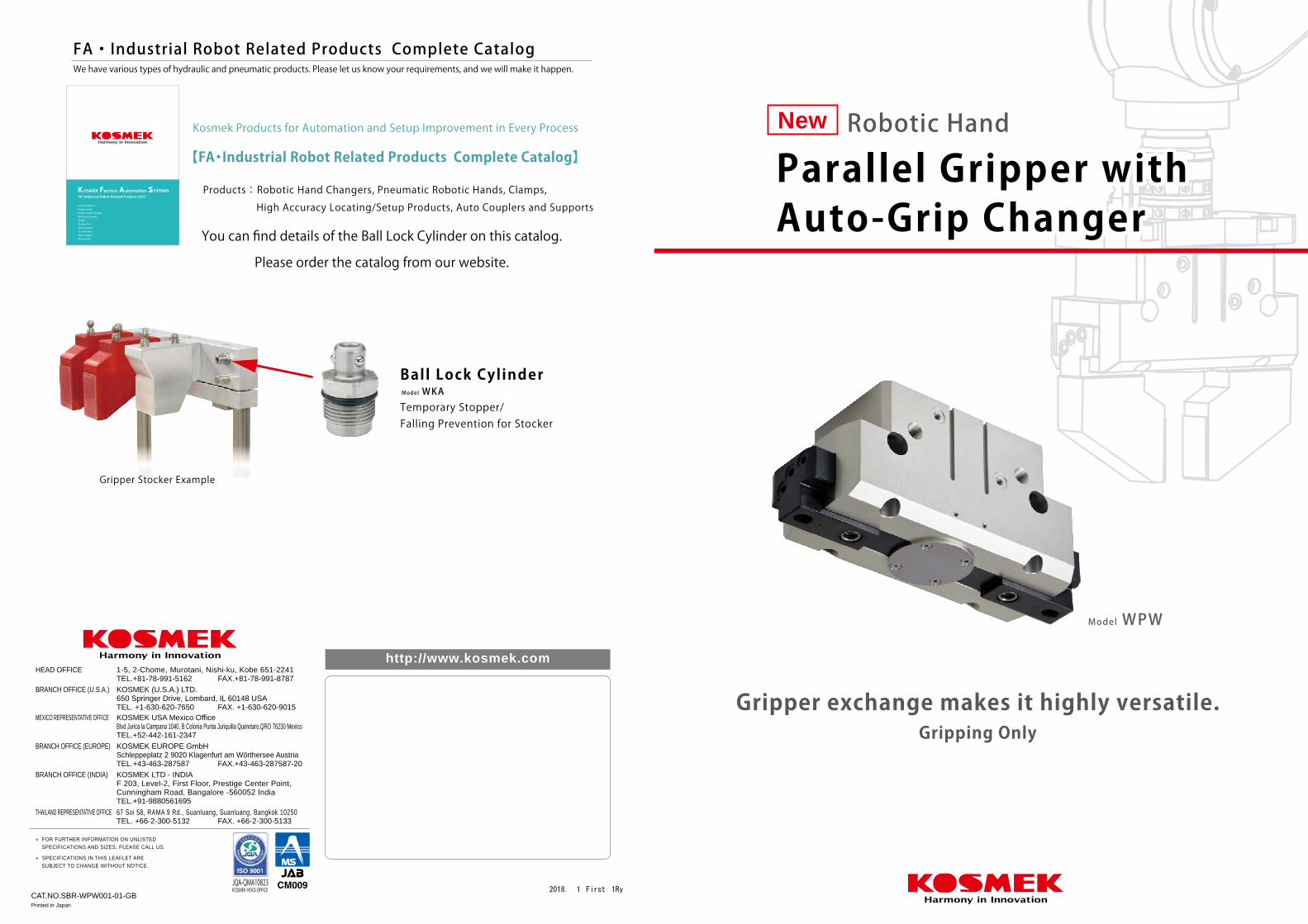
new parallel gripper with high accuracy locating/setup
TRANSCRIPT
CAT.NO.SBR-WPW001-01-GBPrinted in Japan
2018. 1 First 1Ry
http://www.kosmek.com
JQA-QMA10823KOSMEK HEAD OFFICE
● FOR FURTHER INFORMATION ON UNLISTED SPECIFICATIONS AND SIZES, PLEASE CALL US.
● SPECIFICATIONS IN THIS LEAFLET ARE SUBJECT TO CHANGE WITHOUT NOTICE.
KOSMEK (U.S.A.) LTD.650 Springer Drive, Lombard, IL 60148 USATEL. +1-630-620-7650 FAX. +1-630-620-9015
KOSMEK LTD - INDIAF 203, Level-2, First Floor, Prestige Center Point, Cunningham Road, Bangalore -560052 IndiaTEL.+91-988056169567 Soi 58, RAMA 9 Rd., Suanluang, Suanluang, Bangkok 10250TEL. +66-2-300-5132 FAX. +66-2-300-5133
1-5, 2-Chome, Murotani, Nishi-ku, Kobe 651-2241TEL.+81-78-991-5162 FAX.+81-78-991-8787
HEAD OFFICE
BRANCH OFFICE (U.S.A.)
KOSMEK USA Mexico OfficeBlvd Jurica la Campana 1040, B Colonia Punta Juriquilla Queretaro,QRO 76230 MexicoTEL.+52-442-161-2347
MEXICO REPRESENTATIVE OFFICE
BRANCH OFFICE (INDIA)
THAILAND REPRESENTATIVE OFFICE
KOSMEK EUROPE GmbHSchleppeplatz 2 9020 Klagenfurt am Wörthersee AustriaTEL.+43-463-287587 FAX.+43-463-287587-20
BRANCH OFFICE (EUROPE)
Model WPW
Gripper exchange makes it highly versatile.Gripping Only
You can find details of the Ball Lock Cylinder on this catalog.
Please order the catalog from our website.
Gripper Stocker Example
Parallel Gripper with Auto-Grip ChangerParallel Gripper with Auto-Grip Changer
New Robotic Hand
Temporary Stopper/Falling Prevention for Stocker
Model WKABall Lock Cylinder
Products: Robotic Hand Changers, Pneumatic Robotic Hands, Clamps,
High Accuracy Locating/Setup Products, Auto Couplers and Supports
FA・Industrial Robot Related Products Complete CatalogWe have various types of hydraulic and pneumatic products. Please let us know your requirements, and we will make it happen.
【FA・Industrial Robot Related Products Complete Catalog】
Kosmek Products for Automation and Setup Improvement in Every Process
Auto Switch
JEP
Parallel Gripper withAuto-Grip Changer
WPW
PerformanceCurve
ExternalDimensions
InstallationMethod
AccessoriesAuto Switches
CautionsModel No.Indication
SpecificationsFeatures
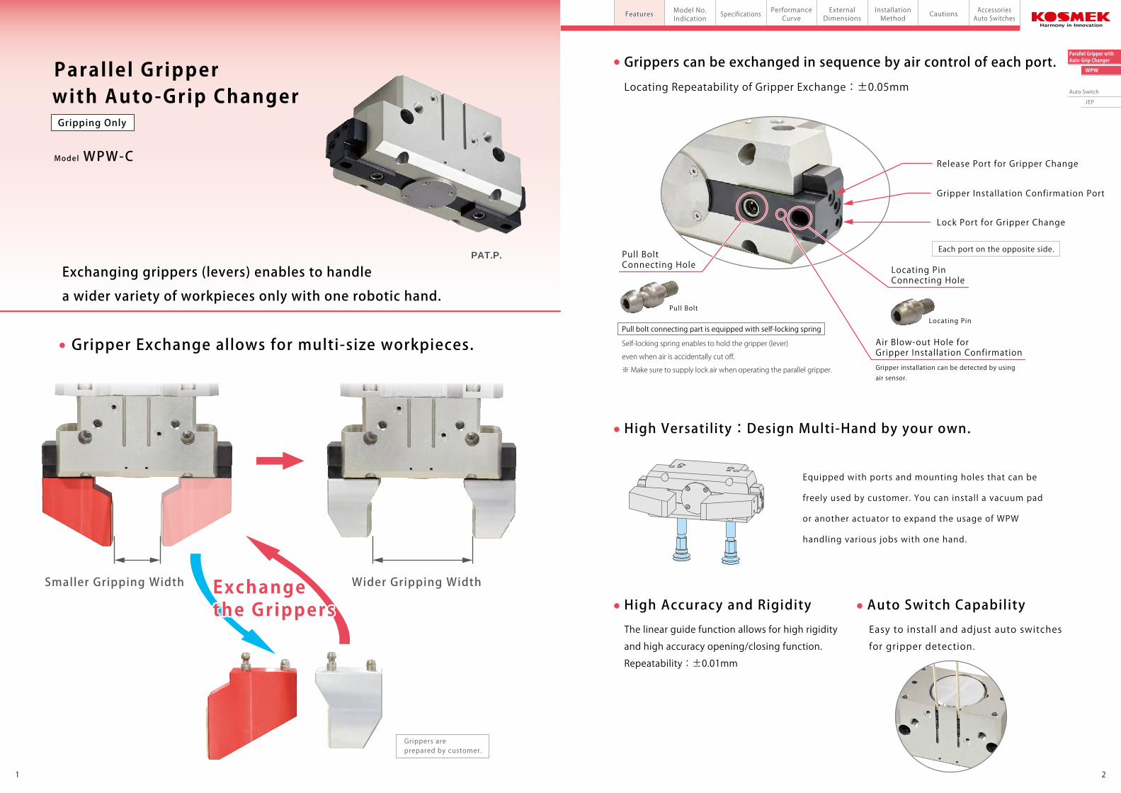
Parallel Gripper
Model WPW-C
a wider variety of workpieces only with one robotic hand.
Exchanging grippers (levers) enables to handle
with Auto-Grip Changer
Gripper Exchange allows for multi-size workpieces.
High Versatility:Design Multi-Hand by your own.
High Accuracy and Rigidity Auto Switch Capability
Grippers can be exchanged in sequence by air control of each port.
Release Port for Gripper Change
Equipped with ports and mounting holes that can be
freely used by customer. You can install a vacuum pad
or another actuator to expand the usage of WPW
handling various jobs with one hand.
Lock Port for Gripper Change
Gripper Installation Confirmation Port
21
Gripping Only
The linear guide function allows for high rigidity
and high accuracy opening/closing function.
Repeatability:±0.01mm
Easy to install and adjust auto switches
for gripper detection.
Each port on the opposite side.
Pull Bolt
Locating Pin
Locating Repeatability of Gripper Exchange:±0.05mm
Wider Gripping WidthSmaller Gripping Width
PAT.P.
Grippers are prepared by customer.
Pull bolt connecting part is equipped with self-locking spring
Self-locking spring enables to hold the gripper (lever)
even when air is accidentally cut off.
※ Make sure to supply lock air when operating the parallel gripper.
Exchangethe Grippers
Pull Bolt Connecting Hole Locating Pin
Connecting Hole
Gripper installation can be detected by using air sensor.
Air Blow-out Hole for Gripper Installation Confirmation
43
Auto Switch
JEP
Parallel Gripper withAuto-Grip Changer
WPW
PerformanceCurve
ExternalDimensions
InstallationMethod
AccessoriesAuto Switches
CautionsModel No.Indication SpecificationsFeaturesPneumatic Robotic Hand Parallel Gripper with Auto-Grip Changer model WPW
3
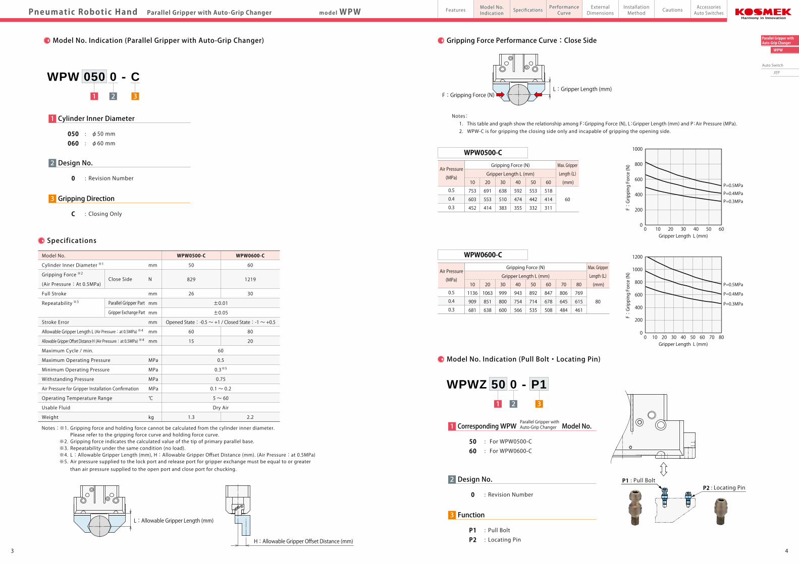
Model No. Indication (Parallel Gripper with Auto-Grip Changer)
Model No. Indication (Pull Bolt・Locating Pin)
Specifications
Notes: ※1. Gripping force and holding force cannot be calculated from the cylinder inner diameter. Please refer to the gripping force curve and holding force curve. ※2. Gripping force indicates the calculated value of the tip of primary parallel base. ※3. Repeatability under the same condition (no load). ※4. L:Allowable Gripper Length (mm), H:Allowable Gripper Offset Distance (mm). (Air Pressure:at 0.5MPa) ※5. Air pressure supplied to the lock port and release port for gripper exchange must be equal to or greater than air pressure supplied to the open port and close port for chucking.
1 2 3
WPW 050 0 - C
3 Gripping Direction
C : Closing Only
2 Design No.
0 : Revision Number
1 Cylinder Inner Diameter
050 : φ50 mm
060 : φ60 mm
±0.01
±0.05
Opened State:-0.5 ~ +1 / Closed State:-1 ~ +0.5
60
0.5
0.3※5
0.75
0.1 ~ 0.2
5 ~ 60
Dry Air
Model No.
Cylinder Inner Diameter ※1 mm
Gripping Force ※2
(Air Pressure:At 0.5MPa)
Full Stroke mm
Repeatability ※3 mm
mm
Stroke Error mm
Allowable Gripper Length L (Air Pressure:at 0.5MPa) ※4 mm
Allowable Gripper Offset Distance H (Air Pressure:at 0.5MPa) ※4 mm
Maximum Cycle / min.
Maximum Operating Pressure MPa
Minimum Operating Pressure MPa
Withstanding Pressure MPa
Air Pressure for Gripper Installation Confirmation MPa
Operating Temperature Range ℃
Usable Fluid
Weight kg
WPW0500-C
50
829
26
60
15
1.3
WPW0600-C
60
1219
30
80
20
2.2
Close Side
Parallel Gripper Part
Gripper Exchange Part
N
L : Allowable Gripper Length (mm)
H : Allowable Gripper Offset Distance (mm)
1 2
WPWZ 50 0 - P1
3 Function
P1 : Pull Bolt P2 : Locating Pin
2 Design No.
0 : Revision Number
50 : For WPW0500-C 60 : For WPW0600-C
P1 : Pull Bolt P2 : Locating Pin
1 Corresponding WPW Model No.Parallel Gripper with Auto-Grip Changer
Gripping Force Performance Curve:Close Side
Air Pressure
(MPa)
0.5
0.4
0.3
WPW0500-C
Gripper Length L (mm)
Gripping Force (N) Max. Gripper
Length (L)
(mm)
60
10
753
603
452
20
691
553
414
30
638
510
383
40
592
474
355
50
553
442
332
60
518
414
311
Notes: 1. This table and graph show the relationship among F:Gripping Force (N), L:Gripper Length (mm) and P:Air Pressure (MPa). 2. WPW-C is for gripping the closing side only and incapable of gripping the opening side.
Air Pressure
(MPa)
0.5
0.4
0.3
WPW0600-C
Gripper Length L (mm)
Gripping Force (N) Max. Gripper
Length (L)
(mm)
80
10
1136
909
681
20
1063
851
638
30
999
800
600
40
943
754
566
50
892
714
535
60
847
678
508
70
806
645
484
80
769
615
461
L : Gripper Length (mm)F : Gripping Force (N)
Gripper Length L (mm)10 20 30 40 50 60 70 800
1200
200
400
600
800
1000
0
F:Gripping Force (N)
Gripper Length L (mm)10 20 30 40 50 600
1000
800
600
400
200
0
F:Gripping Force (N)
P=0.5MPa
P=0.4MPa
P=0.3MPa
P=0.5MPa
P=0.4MPa
P=0.3MPa
65
Auto Switch
JEP
Parallel Gripper withAuto-Grip Changer
WPW
PerformanceCurve
ExternalDimensions
InstallationMethod
AccessoriesAuto Switches
CautionsModel No.Indication
SpecificationsFeaturesPneumatic Robotic Hand Parallel Gripper with Auto-Grip Changer model WPW
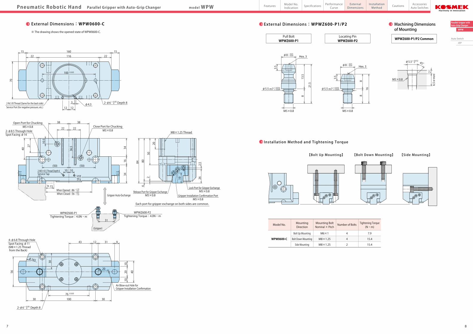
External Dimensions:WPW0500-C
※ The drawing shows the opened state of WPW0500-C.
External Dimensions:WPWZ500-P1/P2 Machining Dimensions of Mounting
Pull BoltWPWZ500-P1 WPWZ500-P1/P2 Common
Locating PinWPWZ500-P2
φ4.3
When Opened : 71When Closed : 45
+ 1.0- 0.5+ 0.5- 1.0
18
(Gripper)
24
45
Ø128 25
17
22.5 80 22.556
30167
7
35.5 10 24 6
15.5 20
2
Each port for gripper exchange on both sides are common.
73 685
47
M8×1.25 Thread
2
Gripper Auto-Exchange
WPWZ500-P2WPWZ500-P1Tightening Torque:2.3N・m Tightening Torque:2.3N・m
13St.
10 10 10.5
(40) (40)
9.5
32.5
23
37
2818
27
3030
2020
Open Port for ChuckingM5×0.8
Close Port for ChuckingM5×0.8
122-Rc1/8 Thread (Same for the back side)Service Port (for negative pressure, etc.) 12
3 2-φ6 Depth 8
80
15.5 15.5
60
13 13125
94
+ 0.05 0
2-φ8.5 Through HoleSpot Facing φ14
2-M3×0.5 Thread Depth 6Service Tap
4-φ6.8 Through HoleSpot Facing φ11(M8×1.25 Thread from the Back)
M3×0.5Release Port for Gripper Exchange
M3×0.5Gripper Installation Confirmation Port
M3×0.5Lock Port for Gripper Exchange
Air Blow-out Hole forGripper Installation Confirmation
2-φ6 Depth 8+ 0.05 0
±0.05
±0.05
7
45°
M4×0.7
18
711
m7
3
3
7
6 or more
1.5
6
13
φ6.6
φ4.5
- 0.01- 0.05
+ 0.016+ 0.004
φ6.6 - 0.01- 0.05
Hex. 2.5
m7φ4.5 + 0.016+ 0.004
M4×0.7
φ4.5 + 0.012 0
M4×0.7
【Bolt Up Mounting】 【Bolt Down Mounting】 【Side Mounting】
Instal lat ion Method and Tightening Torque
Model No.
WPW0500-C
MountingDirection
Bolt Up Mounting
Bolt Down Mounting
Side Mounting
Mounting BoltNominal × Pitch
M6×1
M8×1.25
M8×1.25
Number of Bolts
4
4
2
7.9
15.4
15.4
Hex. 2.5
Tightening Torque(N・m)
87
Auto Switch
JEP
Parallel Gripper withAuto-Grip Changer
WPW
PerformanceCurve
ExternalDimensions
InstallationMethod
AccessoriesAuto Switches
CautionsModel No.Indication
SpecificationsFeaturesmodel WPWPneumatic Robotic Hand Parallel Gripper with Auto-Grip Changer
External Dimensions:WPW0600-C
※ The drawing shows the opened state of WPW0600-C.
External Dimensions:WPWZ600-P1/P2 Machining Dimensions of Mounting
WPWZ600-P1/P2 Common
【Bolt Up Mounting】 【Bolt Down Mounting】 【Side Mounting】
Instal lat ion Method and Tightening Torque
Model No.
WPW0600-C
MountingDirection
Bolt Up Mounting
Bolt Down Mounting
Side Mounting
Mounting BoltNominal × Pitch
M6×1
M8×1.25
M8×1.25
Number of Bolts
4
4
2
7.9
15.4
15.4
Tightening Torque(N・m)
Pull BoltWPWZ600-P1
Locating PinWPWZ600-P2
Gripper Auto-Exchange
88
16
(Gripper)
10.5
50
804
84
2 19 262.5
22116221516015
100
70
12 12
3
22 22
38 38
10.5
36.527
40 3416
34
φ165
56
30
43 12 31 9
20
3010030
76
1020
10
40
31
10 10
813.5
21.5
3.5
Hex. 3
2
φ4.3
(50) (50)
15St.
When Opened : 86When Closed : 56
+ 1.0- 0.5+ 0.5- 1.0
20
φ8- 0.01- 0.05
m7φ5.5 + 0.016+ 0.004
M5×0.8 M5×0.8
m7φ5.5 + 0.016+ 0.004
Hex. 3
6.5 or more
45°φ5.5+ 0.012 0
M5×0.83.5
φ8- 0.01- 0.05
±0.05
±0.05
M5×0.8Lock Port for Gripper Exchange
M5×0.8Release Port for Gripper Exchange
M5×0.8Gripper Installation Confirmation Port
M8×1.25 Thread
Each port for gripper exchange on both sides are common.
WPWZ600-P2Tightening Torque:4.0N・m
WPWZ600-P1Tightening Torque:4.0N・m
2-M3×0.5 Thread Depth 6Service Tap
Open Port for ChuckingM5×0.8 Close Port for Chucking
M5×0.82-φ8.5 Through HoleSpot Facing φ14
2-φ6 Depth 8+ 0.05 02-Rc1/8 Thread (Same for the back side)
Service Port (for negative pressure, etc.)
Air Blow-out Hole forGripper Installation Confirmation
4-φ6.8 Through HoleSpot Facing φ11(M8×1.25 Thread from the Back)
2-φ6 Depth 8+ 0.05 0
109
Auto Switch
JEP
Parallel Gripper withAuto-Grip Changer
WPW
model WPWPerformanceCurve
ExternalDimensions
InstallationMethod
AccessoriesAuto Switches
CautionsModel No.Indication
SpecificationsFeaturesPneumatic Robotic Hand Gripper Length/Workpiece Weight Graph
Gripper Length/Workpiece Weight Graph
How to Read Gripper Length/Workpiece Weight Graph
Relationship between Workpiece Weight and Robotic Hand Gripping Force
Inertial Force・Friction Coefficient・Safety Factor Selection List
Note: ※1. Indicates the friction coefficient of contact surface of workpiece and gripper. Refer to the condition below. Friction Coefficient:Small (Approximately μ=0.1) … When contact surface is flat. Friction Coefficient:Large (More than μ=0.15) … When contact surface is serration or spike shape.
【Ex. 1】 When using WPW0600-C (close side) with 10kg workpiece and 30mm gripper, the safety factor should be 10 times. When using it with lower speed which is indicated in Inertial Force・Friction Coefficient・Safety Factor Selection List, the friction coefficient of contact surface can be small. When using it with middle speed (stops after 0.1 sec at the speed of 100~300mm/sec.), contact surface should be serration or spike shape to secure larger friction coefficient.
The selection method is a reference. It is recommended to consider the actual conditions (environment) when selecting the product.The graph shows when air pressure is 0.5MPa.
The safety factor of robotic hand gripping force to workpiece weight should be approximately 16 times for each robot manufacturer, but it differs according to the conditions. Refer to the following contents when selecting the product.
① Workpiece Gravity Center and Gripping Position It is recommended to design the gripper so that it grips the workpiece gravity center with the center of robotic hand.② Gripper Length The load applied on the robotic hand body depends on the gripper length. It is recommended to design the gripper so that the workpiece gravity center is as close as possible to the robotic hand.
【Ex. 2】 When using it with middle speed (stops after 0.1 sec at the speed of 300~500mm/sec.) and when friction coefficient is small due to flat contact surface, the safety factor should be 20 times. When using WPW0600-C (close side) with 20 times safety factor and 20mm gripper, the maximum workpiece weight is 5.4kg.
WPW-C:Close Side
Air Pressure0.5 MPa
Inertial Force
WPW0600-C
00 5 10 2515 20
W:Workpiece Weight (kg)
L:Gripper Length (mm)
80
70
60
50
20
30
40
10
Safety Factor 15 Safety Factor 10
WPW0500-C
00 5 10 2015
W:Workpiece Weight (kg)
L:Gripper Length (mm)
60
50
40
30
20
10
Safety Factor 20
Safety Factor 5
Safety Factor 15 Safety Factor 10
L : Gripper Length (mm)
W : Workpiece Weight (kg)
Safety Factor 20
Safety Factor 5
Air Pressure0.5 MPa
L : Gripper Length (mm)
W : Workpiece Weight (kg)
WPW0600-C
00 5 10 2515 20
W:Workpiece Weight (kg)
L:Gripper Length (mm)
80
70
60
50
20
30
40
10
Safety Factor 15 Safety Factor 10
Safety Factor 20 Safety Factor 5
Safety Factor 10
5.4
Inertial Force Friction Coefficient
Large
Small
Large
Small
Large
Small
Safety Factor
5 times
10 times
10 times
15 times
15 times
20 times
- 30 times
Stops after 0.1 sec
at the speed of 0~100mm/sec.
Stops after 0.1 sec
at the speed of 100~300mm/sec.
Stops after 0.1 sec
at the speed of 300~500mm/sec.
Stops after 0.1 sec
at the speed of 500~1000mm/sec.
※1
LowSpeed
MiddleSpeed
HighSpeed
Gripper
Workpiece
Friction Coefficient of Contact Surface of Workpiece and Gripper
Ex.1
Ex.2
1211
Auto Switch
JEP
Parallel Gripper withAuto-Grip Changer
WPW
PerformanceCurve
ExternalDimensions
InstallationMethod
AccessoriesAuto Switches
CautionsModel No.Indication
SpecificationsFeaturesmodel WPWPneumatic Robotic Hand Cautions
● Notes for Design
1)Check Specifications
● Model WPW: Maximum operating air pressure is 0.5 MPa.
Minimum operating air pressure is 0.3 MPa.
However, the maximum operating pressure and gripping force
may change depending on the gripper length.
Please use with appropriate air pressure in order to avoid
deformation, galling or air leakage caused by overload
applied to the robotic hand.
● Parallel Gripper with Auto-Grip Changer (model WPW) grips
with the close side.
2)Clamp a workpiece at the center of Parallel Gripper.
● Not designed for offset clamping.
3)Do not apply impact on the gripper (prepared by customer).
● Otherwise, it may result in breakage of the product.
4)Locating of the Body
● The Parallel Gripper can be located by using its pin holes.
Please consider pin position dimension tolerance and
pin hole tolerance when using a locating pin.
Locating pin is not included.
5)Notes for Circuit Design
● Please design the air circuit properly and review the circuit
design in advance in order to avoid malfunction or breakage
of the device.
● Parallel Gripper and Auto-Grip Changer must be controlled by
different circuits. Air pressure of Auto-Grip Changer must be equal
to or greater than that of Parallel Gripper. When using Parallel Gripper,
continuously supply air pressure to the lock side of Auto-Grip Changer.
6)Please supply filtered clean dry air.
● Oil supply with a lubricator etc. is unnecessary.
7)Adjustment of Operating Speed
● If the operating speed of the robotic hand is very fast, it leads
to wear-out or malfunction of the parts. Please prepare a
speed controller to adjust speed in order not to exceed the
appropriate opening and closing time.
8)Operating Environment
● WPW has no function that prevents foreign substances.
Do not use under environment with coolant and cutting chips.
9)Protective Cover Installation
● If the moving parts of the robot or robotic hand may endanger
human life, please install the protection cover.
10)Fall Prevention Measures
● In case of accident such as detachment of a workpiece,
please prepare fall prevention measures for safety.
11)Gripper Installation Confirmation
● Gripper installation confirmation is available by using the gap sensor.
Supply air to the air sensor must be clean dry air that is filtered
through the filter of 5μm or less. Make sure the gripper securely
seals the air blow-out hole for gripper installation confirmation.
【Recommended Sensors】
SMC Corporation :Air Catch Sensor Series ISA3-F, ISA3-G, ISA2-G
CKD Corporation : Air Catch Sensor Series GPS2-05-15
Recommended Air Pressure :0.1 ~ 0.2MPa
1)Check the Fluid to Use
● Please supply filtered clean dry air. (Install drain removing device.)
● Oil supply with a lubricator etc. is unnecessary. Oil supply
with a lubricator may cause loss of the initial lubricant.
The operation under low pressure and low speed may be unstable.
(When using secondary lubricant, please supply lubricant
continuously. Otherwise, the initial grease applied from
KOSMEK will be removed from the secondary lubricant. )
2)Procedure before Piping
● The pipeline, piping connector and fixture circuits
should be cleaned and flushed thoroughly.
The dust and cutting chips in the circuit may lead to
fluid leakage and malfunction.
● There is no filter provided with this product for prevention
of contaminants in the air circuit.
3)Applying Sealing Tape
● When using sealing tape, wrap with it 1 to 2 times following
the screwing direction. When piping, be careful that contaminant
such as sealing tape does not enter in products.
Pieces of the sealing tape can cause air leaks and malfunction.
4)Product Installation
● Please use hexagon socket bolts (with tensile strength of A2-70
or greater), and tighten the product with the tightening torque
listed on P.6 and P.8.
● The tightening torque for pull bolt and locating pin is shown below.
● Installation failure causes air leaks, deformation and damage
of the robotic hand.
5)Trial Operation Method
● Avoid supplying large air flow right after the installation.
The operating time will be very fast and the robotic hand
may be seriously damaged. Please install the speed controller
near the air source and gradually supply air pressure.
6)Adjustment of Operating Speed
● If the operating speed of the robotic hand is very fast,
it leads to wear-out or malfunction of the parts.
Please prepare a speed controller to adjust speed in order
not to exceed the appropriate opening and closing time.
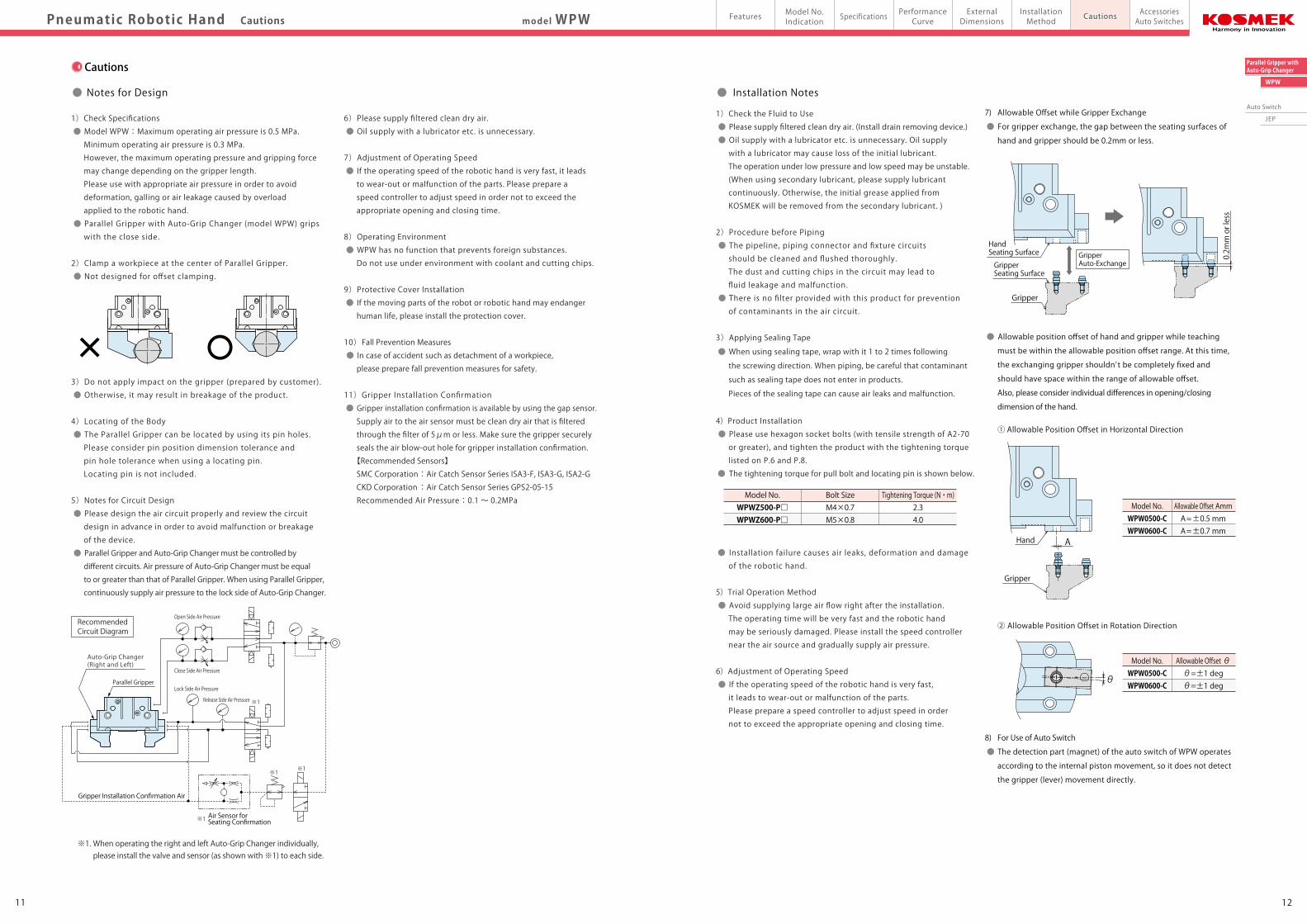
● Installation Notes
Model No.WPWZ500-P□WPWZ600-P□
Bolt SizeM4×0.7M5×0.8
Tightening Torque (N・m)2.34.0
7) Allowable Offset while Gripper Exchange
● For gripper exchange, the gap between the seating surfaces of
hand and gripper should be 0.2mm or less.
● Allowable position offset of hand and gripper while teaching
must be within the allowable position offset range. At this time,
the exchanging gripper shouldn’t be completely fixed and
should have space within the range of allowable offset.
Also, please consider individual differences in opening/closing
dimension of the hand.
① Allowable Position Offset in Horizontal Direction
② Allowable Position Offset in Rotation Direction
8) For Use of Auto Switch
● The detection part (magnet) of the auto switch of WPW operates
according to the internal piston movement, so it does not detect
the gripper (lever) movement directly.
Model No.WPW0500-CWPW0600-C
Allowable Offset AmmA=±0.5 mmA=±0.7 mm
Model No.WPW0500-CWPW0600-C
Allowable Offset θθ=±1 degθ=±1 deg
Cautions
Gripper Auto-Exchange
Gripper
HandSeating Surface
GripperSeating Surface
0.2mm or less
AHand
Gripper
θClose Side Air Pressure
Open Side Air PressureRecommended Circuit Diagram
※1
※1
※1※1
Lock Side Air Pressure
Release Side Air Pressure
Parallel Gripper
Auto-Grip Changer(Right and Left)
Seating ConfirmationAir Sensor for
※1. When operating the right and left Auto-Grip Changer individually, please install the valve and sensor (as shown with ※1) to each side.
Gripper Installation Confirmation Air
1413
Auto Switch
JEP
Parallel Gripper withAuto-Grip Changer
WPW
PerformanceCurve
ExternalDimensions
InstallationMethod
AccessoriesAuto SwitchesCautionsModel No.
IndicationSpecificationsFeaturesmodel WPW/JEP
1)Warranty Period
● The product warranty period is 18 months from shipment from
our factory or 12 months from initial use, whichever is earlier.
2)Warranty Scope
● If the product is damaged or malfunctions during the warranty
period due to faulty design, materials or workmanship, we will
replace or repair the defective part at our expense.
Defects or failures caused by the following are not covered.
① If the stipulated maintenance and inspection are not carried out.
② If the product is used while it is not suitable for use based on
the operator’s judgment, resulting in defect.
③ If it is used or handled in inappropriate way by the operator.
(Including damage caused by the misconduct of the third party.)
④ If the defect is caused by reasons other than our responsibility.
⑤ If repair or modifications are carried out by anyone other than Kosmek,
or without our approval and confirmation, it will void warranty.
⑥ Other caused by natural disasters or calamities not attributable to
our company.
⑦ Parts or replacement expenses due to parts consumption and
deterioration.
(Such as rubber, plastic, seal material and some electric components.)
Damages excluding from direct result of a product defect shall be
excluded from the warranty.
● Warranty
1)Removal of the Product and Shut-off of Pressure Source
● Before the product is removed, make sure that the
above-mentioned safety measures are in place. Shut off the
air of hydraulic source and make sure no pressure exists in
the hydraulic and air circuit.
● Make sure there is no abnormality in the bolts and respective
parts before restarting.
2)Clean the product regularly.
● Using the product contaminated with dirt may lead to damage
of the product or detachment of a workpiece due to lack of
gripping force and malfunctioning, etc.
3)Regularly tighten pipings, mounting bolts, etc. to ensure
proper use.
4)Make sure there is smooth action and no abnormal noise.
● Especially when it is restarted after left unused for a long
period, make sure it can be operated correctly.
5)The products should be stored in the cool and dark place
without direct sunshine or moisture.
6)Please contact us for overhaul and repair.
Built-in spring is very strong and can be dangerous.
● Maintenance and Inspection● Notes on Handling
1)It should be handled by qualified personnel.
● The hydraulic and pneumatic equipment should be handled
and maintained by qualified personnel.
2)Do not handle or remove the product unless safety
protocols are ensured.
① The machine and equipment can only be inspected or prepared
when it is confirmed that the preventive devices are in place.
② Before the product is removed, make sure that the above-mentioned
safety measures are in place. Shut off the air of hydraulic source
and make sure no pressure exists in the hydraulic and air circuit.
③ After stopping the product, do not remove until the equipment
cools down.
④ Make sure there is no abnormality in the bolts and respective
parts before restarting the machine or equipment.
3)In order to avoid injury, please do not touch the robotic hand
or robot while they are operating.
4) When the robot is in operation, make sure the safety of
environment in case of a workpiece detachment.
5)Do not disassemble or modify.
● If the equipment is taken apart or modified, the warranty
will be voided even within the warranty period.
● Built-in spring is very strong and can be dangerous.
Pneumatic Robotic Hand Cautions・Auto Switch
Auto Switch
Note :
1. The detection part (magnet) of the auto switch of WPW operates according to the internal piston movement,
so it does not detect the hand (gripper・lever) movement directly.
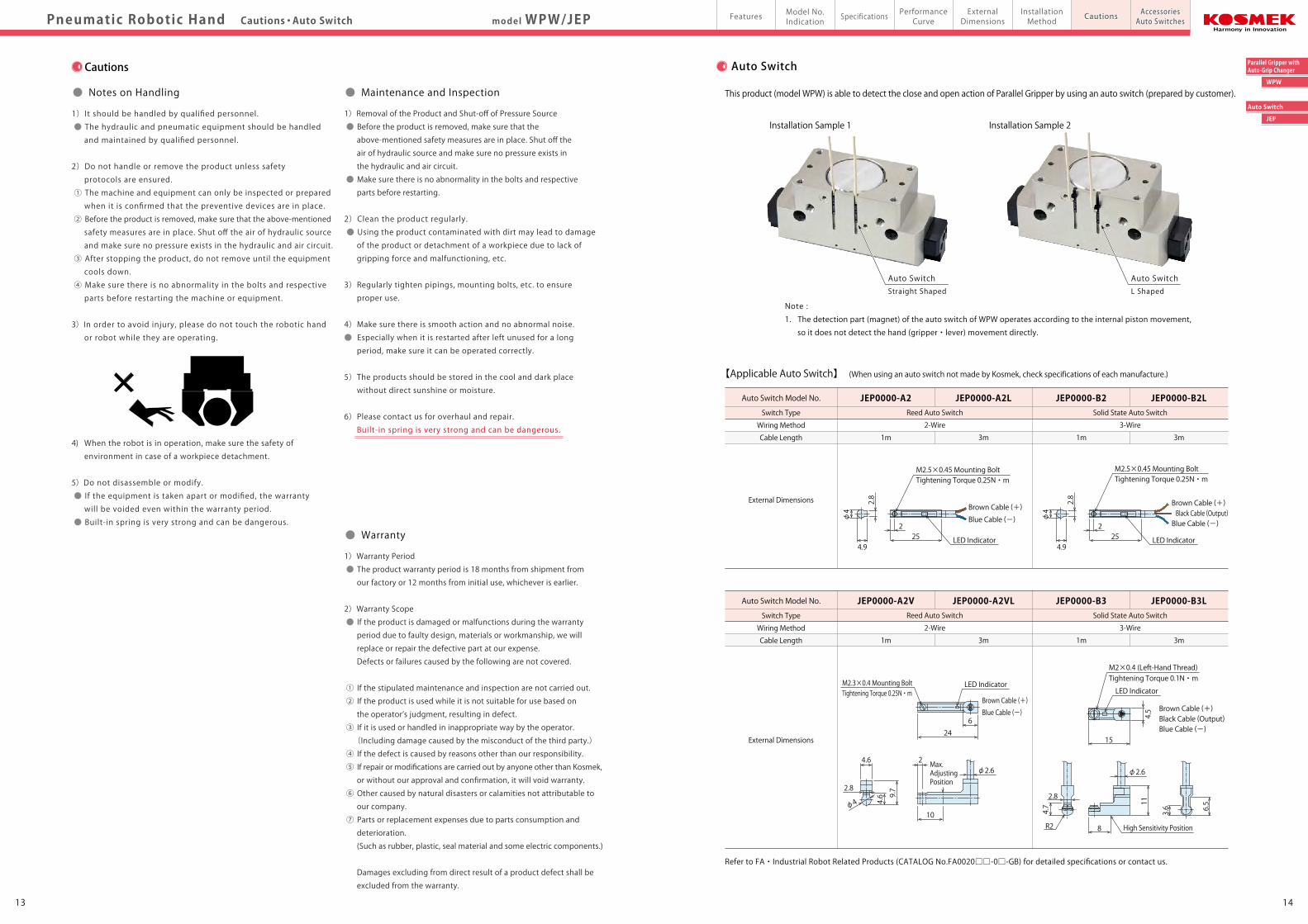
This product (model WPW) is able to detect the close and open action of Parallel Gripper by using an auto switch (prepared by customer).
Installation Sample 2Installation Sample 1
Auto Switch Model No.
Switch Type
Wiring Method
Cable Length
External Dimensions
Reed Auto Switch
2-Wire
JEP0000-A2 JEP0000-A2LSolid State Auto Switch
3-Wire
JEP0000-B2 JEP0000-B2L
1m 3m 1m 3m
【Applicable Auto Switch】 (When using an auto switch not made by Kosmek, check specifications of each manufacture.)
4.9
2.8
φ4
252
Brown Cable (+)
Blue Cable (-)
M2.5×0.45 Mounting BoltTightening Torque 0.25N・m
4.9
2.8
φ4
252
Brown Cable (+)
Blue Cable (-)Black Cable (Output)
Brown Cable (+)
Blue Cable (-)Black Cable (Output)
Auto Switch Model No.
Switch Type
Wiring Method
Cable Length
External Dimensions
Reed Auto Switch
2-Wire
JEP0000-A2V JEP0000-A2VLSolid State Auto Switch
3-Wire
JEP0000-B3 JEP0000-B3L
1m 3m 1m 3m
24
6
Brown Cable (+)
Blue Cable (-)
4.6
2.8
φ4
9.7
4.6
15
R2
2.8
8 High Sensitivity Position
4.7
4.5
11
3.6 6.5
φ2.6
Refer to FA・Industrial Robot Related Products (CATALOG No.FA0020□□-0□-GB) for detailed specifications or contact us.
Auto SwitchStraight Shaped
Auto SwitchL Shaped
Cautions
M2.5×0.45 Mounting BoltTightening Torque 0.25N・m
LED Indicator LED Indicator
LED IndicatorLED Indicator
M2×0.4 (Left-Hand Thread)Tightening Torque 0.1N・mM2.3×0.4 Mounting Bolt
Tightening Torque 0.25N・m
2
10
φ2.6Max.Adjusting Position