new quadrotor manipulation system inverse … · control of the proposed quadrotor manipulation...
TRANSCRIPT

International Journal of Recent advances in Mechanical Engineering (IJMECH) Vol.4, No.3, August 2015
DOI : 10.14810/ijmech.2015.4304 39
NEW QUADROTOR MANIPULATION SYSTEM:
INVERSE KINEMATICS, IDENTIFICATION AND
RIC-BASED CONTROL
Ahmed Khalifa 1 1, Mohamed Fanni 2 , Ahmed Ramadan 3 and Ahmed Abo-Ismail 4
1,2,4 Department of Mechatronics and Robotics Engineering
Egypt-Japan University of Science and Technology, New Borg-El-Arab city, Alexandria,
Egypt 2 On leave from Department of Production Engineering and Mechanical Design
Mansoura University, Mansoura, Egypt 3 Department of Computer and Automatic Control Engineering
Tanta University, Tanta, Egypt1
ABSTRACT
This paper presents the inverse kinematic analysis and parameters identification of a novel aerial
manipulation system. This system consists of 2-link manipulator attached to the bottom of a quadrotor. This
new system presents a solution for the limitations found in the current quadrotor manipulation system. By
deriving the inverse kinematics, one can design the controller such that the desired end effector position and
orientation can be tracked. To study the feasibility of the proposed system, a quadrotor with high enough
payload to add the 2-link manipulator is designed and constructed. Experimental setup of the system is
introduced with an experiment to estimate the rotors parameters. Its parameters are identified to be used in
the simulation and controller design of the proposed system. System dynamics are derived briefly based on
Newton Euler Method. The controller of the proposed system is designed based on Robust Internal-loop
Compensator (RIC) and compared to Fuzzy Model Reference Learning Control (FMRLC) technique which
was previously designed and tested for the proposed system. These controllers are tested for provide system
stability and trajectory tracking under the effect of picking as well as placing a payload and under the effect
of changing the operating region. Simulation framework is implemented in MATLAB/SIMULINK
environment. The simulation results indicate the effectiveness of the inverse kinematic analysis and the
proposed control technique.
KEYWORDS
Aerial Manipulation, Identification, Position Kinematic Analysis, Demining, Inspection, Transportation,
Robust Internal-loop Compensator
1. INTRODUCTION
Quadrotor is one of the Unmanned Aerial Vehicles (UAVs) which offer possibilities of speed and
access to regions that are otherwise inaccessible to ground robotic vehicles. Quadrotor vehicles
International Journal of Recent advances in Mechanical Engineering (IJMECH) Vol.4, No.3, August 2015
40
possess certain essential characteristics, such as small size and cost, Vertical Take Off and Landing
(VTOL), performing slow precise movements, and impressive maneuverability, which highlight
their potential for use in vital applications. Such applications include; homeland security (e.g.
Border patrol and surveillance), and earth sciences (to study climate change, glacier dynamics, and
volcanic activity) [23], [4], [11], and [1]. However, most research on UAVs has typically been
limited to monitoring and surveillance applications where the objectives are limited to "look" and
"search" but "do not touch". Due to their superior mobility, much interest is given to utilize them
for mobile manipulation such as inspection of hard-to-reach structures or transportation in remote
areas. Previous research on aerial manipulation can be divided into three categories. The first
approach is to install a gripper at the bottom of an UAV to hold a payload. In [2], [18], and [28], a
quadrotor with a gripper is used for transporting blocks and to build structures. The second
approach is to suspend a payload with cables. In [10], an adaptive controller is presented to avoid
swing excitation of a payload. In [20], specific attitude and position of a payload is achieved using
cables connected to three quadrotors. The other types of research are concerned about interaction
with existing structures, as example, for contact inspection. In [27] and [7] research has been
conducted on utilizing a force sensor or a brush as a manipulator. However, the above approaches
have limitations for manipulation.
For the first category using a gripper, payloads are rigidly connected to the body of an UAV.
Accordingly, not only the attitude of the payload is restricted to the attitude of the UAV, but also
the accessible range of the end effector is confined because of the UAV body and blades. In the
second type using cables, the movement of the payload cannot be always regulated directly because
manipulation is achieved using a cable which cannot always drive the motion of the payload as
desired. The last cases are applicable to specialized missions such as wall inspection or applying
normal force to a surface.
To overcome these limitations, one alternative approach is to equip an aerial vehicle with a robotic
manipulator that can actively interact with the environment. For example, in [17], a test bed
including four-DOF robot arms and a crane emulating an aerial robot is proposed. By combining
the mobility of the aerial vehicle with the versatility of a robotic manipulator, the utility of mobile
manipulation can be maximized. When employing the robotic manipulator, the dynamics of the
robotic manipulator is highly coupled with of the aerial vehicle, which should be carefully
considered in the controller design for the aerial vehicle. Also, an aerial robot needs to tolerate the
reaction forces from the interactions with the object or external environment. These reaction forces
may affect the stability of an aerial vehicle significantly.
In [21], we propose a new aerial manipulation system that consists of a 2-link manipulator attached
to the bottom of a quadrotor. This new system presents a solution for the limitations found in the
current quadrotor manipulation system. It has the capability of manipulating the objects with
arbitrary location and orientation (DOF are increased from 4 to 6), the manipulator provides
sufficient distance between quadrotor and object location, and it is considered as the
minimum manipulator weight for aerial manipulation. In [15], The dynamic model of this
system is derived taking into account the effect of adding a payload to the manipulator, in
addition to, the design of two controllers namely, Direct Fuzzy Logic controller and Fuzzy
Model Reference Learning Control applied to this system, are presented. The simulation
results indicate the outstanding performance of the FMRLC and the feasibility of the proposed robot. This proposed system opens new application area for robotics. Such applications
are inspection, maintenance, firefighting, service robot in crowded cities to deliver light stuff such

International Journal of Recent advances in Mechanical Engineering (IJMECH) Vol.4, No.3, August 2015
41
as post mails or quick meals, rescue operation, surveillance, demining, performing tasks in
dangerous places, or transportation in remote places.
In [22], a quadrotor with light-weight manipulators are tested, although the movement of
manipulator is not explicitly considered during the design of the PID controller. In [16], an aerial
manipulation using a quadrotor with a 2 DOF robotic arm is presented but with different
configuration from us. It did not provide a solution for the limited DOFs problem of aerial
manipulation, in addition to, it did not provide explicit solution to the inverse kinematics problem.
In this paper the design, kinematic (forward and inverse) and dynamic analysis (including effect of
adding a payload to the manipulator end effector), experiment to identify rotors parameters, and
control of the proposed quadrotor manipulation system based on RIC, are presented.
This paper is organized as following. Design of the proposed system is described in section 3.
Section 4 introduces the system kinematic and dynamic analysis. The rotors parameters
identification experiment is described in section 5. The proposed control system is presented in
section 6. In section 7, simulation results using MATLAB/SIMULINK are presented. Finally, the
main contributions are concluded in section 8.
2. DESIGN OF THE PROPOSED SYSTEM
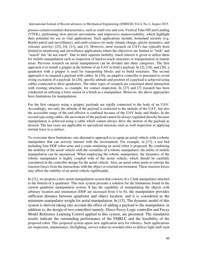
The structure of the proposed system is shown in Fig. 1. The proposed quadrotor manipulation
system consists mainly from two parts; the quadrotor and the manipulator.
2.1 The Two-Link Manipulator
The design of this manipulator is based on light weight and enough workspace under the quadrotor.
Our target is to design a light and simple 2 DOF manipulator that can carry as much as possible of
a payload. One of the available and famous company to sell the components of such type of
manipulator is "lynxmotion" [19]. The arm components are selected, purchased and assembled
such that the total weight of arm is 200 g and can carry a payload of 200 g [14]. The arm
components are:
• Three servo motors: HS-422 for gripper, HS-5485HB for joint 1, and HS-422 for joint 2.
• Serial servo controller (SSC-32): Interface between the main control unit and the servo
motors.
• Arduino board (Mega 2560) [8]: Implement manipulator control algorithm.
• PS2 R/C: Remote controller to send commands to manipulator.
• Motor accessories: Aluminum Tubing - 1.50 in, Aluminum Multi-Purpose Servo Bracket
Two Pack, Aluminum Tubing Connector Hub, and Aluminum Long "C" Servo Bracket
with Ball Bearings Two Pack.
2.2 Quadrotor
The quadrotor components are selected such that it can carry payload = 500 g (larger than the total
arm weight including the maximum payload value). Asctec pelican quadrotor [9] is used as the
quadrotor platform with the following specification: Autopilot sensor board - Magnetometer - GPS
receiver - Futuba R/C - X-bee- 11.1V LiPo battery - 1.6 GHz Intel Atom processor board - wireless
International Journal of Recent advances in Mechanical Engineering (IJMECH) Vol.4, No.3, August 2015
42
LAN access point.
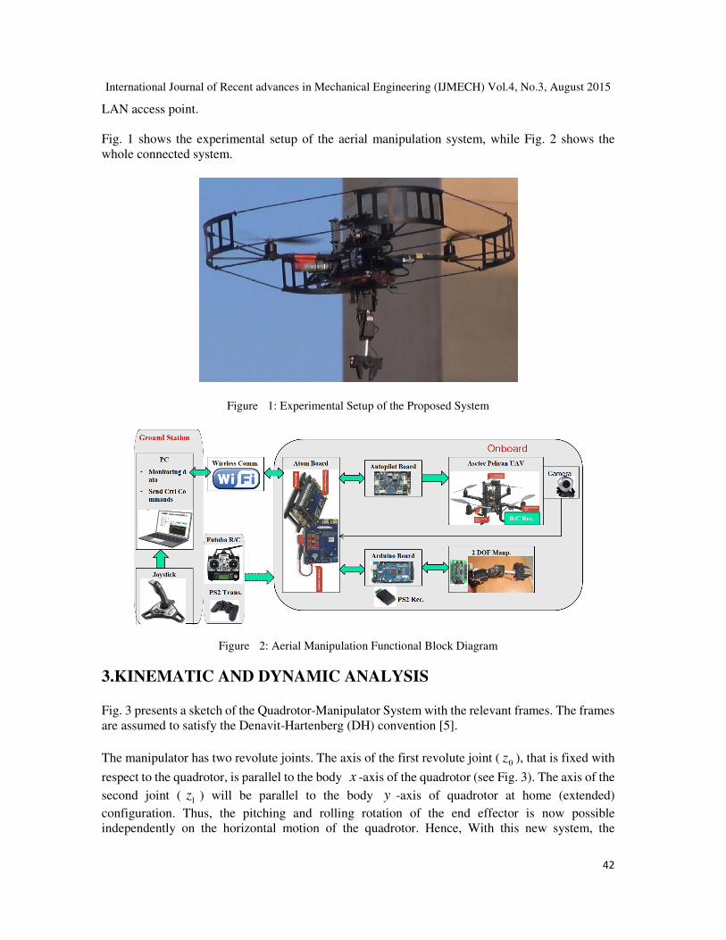
Fig. 1 shows the experimental setup of the aerial manipulation system, while Fig. 2 shows the
whole connected system.
Figure 1: Experimental Setup of the Proposed System
Figure 2: Aerial Manipulation Functional Block Diagram
3.KINEMATIC AND DYNAMIC ANALYSIS
Fig. 3 presents a sketch of the Quadrotor-Manipulator System with the relevant frames. The frames
are assumed to satisfy the Denavit-Hartenberg (DH) convention [5].
The manipulator has two revolute joints. The axis of the first revolute joint ( 0z ), that is fixed with
respect to the quadrotor, is parallel to the body x -axis of the quadrotor (see Fig. 3). The axis of the
second joint ( 1z ) will be parallel to the body y -axis of quadrotor at home (extended)
configuration. Thus, the pitching and rolling rotation of the end effector is now possible
independently on the horizontal motion of the quadrotor. Hence, With this new system, the

International Journal of Recent advances in Mechanical Engineering (IJMECH) Vol.4, No.3, August 2015
43
capability of manipulating objects with arbitrary location and orientation is achieved because the
DOF are increased from 4 to 6.
Figure 3: Schematic of Quadrotor Manipulation System Frames
3.1 Kinematics
The rotational kinematics of the quadrotor is represented through Euler angles. A rigid body is
completely described by its position and orientation with respect to reference frame E , IO - X
Y Z , that it is supposed to be earth-fixed and inertial. Let define 1η as
TZYX ],,[=1η (1)
the vector of the body position coordinates in the earth-fixed reference frame. The vector 1η& is the
corresponding time derivative. If one defines
Twvu ],,[=1ν (2)
as the linear velocity of the origin of the body-fixed frame B , BO - x y z , whose origin is
coincident with the center of mass (CM ), with respect to the origin of the earth-fixed frame
expressed in the body-fixed frame, the following relation between the defined linear velocities
holds:
11 = ην &B
IR (3)
where B
IR is the rotation matrix expressing the transformation from the inertial frame to the
body-fixed frame.
Let define 2η as

International Journal of Recent advances in Mechanical Engineering (IJMECH) Vol.4, No.3, August 2015
44
T],,[=2 ψθφη (4)
the vector of body Euler-angle coordinates in an earth-fixed reference frame. Those are commonly
named roll, pitch and yaw angles and corresponds to the elementary rotation around X , Y and
Z in fixed frame. The vector 2η& is the corresponding time derivative (expressed in the inertial
frame). Let define
Trqp ],,[=2ν (5)
as body-fixed angular velocity. The vector 2η& is related to the body-fixed angular velocity by a
proper Jacobian matrix:
22 = ην &vJ (6)
The matrix vJ can be expressed in terms of Euler angles as:
−
−
)()()(0
)()()(0
)(01
=φθθ
φθφ
θ
CCS
SCC
S
Jv (7)
where )(αC and )(αS are short notations for )(αcos and )(αsin . The rotation B
IR matrix
needed to transform the linear velocities, is expressed in terms of Euler angles by the following:
+−+
++−
−
)()()()()()()()()()()()(
)()()()()()()()()()()()(
)()()()()(
=φθφθψφψφθψφψ
φθφθψφψψθψφψ
θθψθψ
CCCSSSCCSCSS
SCSSSCCCSSCS
SCSCC
RB
I (8)
The DH parameters for the 2-Link manipulator are derived and presented in [21].
The position and orientation of the end effector relative to the body-fixed frame is easily obtained
by multiplying the following homogeneous transformation matrices B
A0 , 0
1A , 1
2A .

International Journal of Recent advances in Mechanical Engineering (IJMECH) Vol.4, No.3, August 2015
45
3.1.1 Forward Kinematics
Let define the position and orientation of the end effector expressed in the inertial frame, as 1
eeη
and 2
eeη respectively.
T
eeeeeeee zyx ],,[=1
η (9)
T
eeeeeeee ],,[=2
ψθφη (10)
The forward kinematics problem consists of determining the operational coordinates (1
eeη and
2eeη ) of the end effector, as a function of the quadrotor movements ( X , Y , Z , and ψ ) as well
as the motion of the manipulator’s joints ( 1θ and 2θ ). This problem is solved by computing the
homogeneous transformation matrix composed of relative translations and rotations.
The transformation matrix from the body frame to the inertial frame I
BA which is:
),,(*= ZYXtranslRA I
B
I
B (11)
where I
BR is 44x matrix , and ),,( ZYXtransl is 44x matrix that describes the translation of
X , Y and Z in the inertial coordinates. The total transformation matrix that relates the end
effector frame to the inertial frame is IT2 , which is given by:
1
2
0
102 = AAAAT BI
B
I (12)
Define the general form for this transformation matrix as a function of end effector variables(1
eeη
and 2
eeη ), as following:
1000
=333231
232221
131211
ee
ee
ee
ee zrrr
yrrr
xrrr
T (13)
Equating (12) and (13), an expression for the parameters of eeT ( ijr , eex , eey , and eez ;
1,2,3=, ji ) can be found, from which values of the end effector variables can determined. Euler
angles of the end effector ( eeφ , eeθ and eeψ ) can be computed from the rotation matrix of eeT as
in [13].

International Journal of Recent advances in Mechanical Engineering (IJMECH) Vol.4, No.3, August 2015
46
3.1.2 Inverse Kinematics
The inverse kinematics problem consists of determining the quadrotor movements ( X , Y , Z ,
and ψ ) as well as the motion of the manipulator’s joints ( 1θ and 2θ ) as function of operational
coordinates (1
eeη and 2
eeη ) of the end effector.
The inverse kinematics solution is essential for the robot’s control, since it allows to compute the
required quadrotor movements and manipulator joints angles to move the end effector to a desired
position and orientation.
The rotations of the end effector can be parameterized by using several methods one of them, that is
chosen, is the euler angles [13].
Equation (12) can be expressed, after putting φ = θ = 0, since we apply for point-to-point
control because we target end effector control during picking and placing positions (reset
configuration), as following:
−−−−
−+−−+−
+++−+
1000
)()()()()()()()(
)()()()()()()()()()()()()()()()()()()(
)()()()()()()()()()()()()()()()()()()(
= 12211012112
21222111212212
21222111212212
2 θθθθθθθθ
θθψθψθψθψθθψψθθθψθψ
ψθθθψψθθψθψθθψψθθθψ
SCLSLLZCSSSC
CCCLSSLCCLYSCSCCSCCCCSS
SCCLSCLSCLXSSSSCCCSCCSC
TI
(14)
From (14) and (13), the inverse kinematics of the system can be derived. According to the structure
of (14), the inverse orientation is carried out first followed by inverse position. The inverse
orientation has three cases as following:
Case 1:
Suppose that not both of 13r , 23r are zero. Then from (14), we deduce that )( 1θsin ≠ 0 and 33r
≠ ± 1. In the same time, )( 1θcos = 33r and )( 1θsin = ± 2
331 r− and thus,
),12(= 33
2
331 rratan −θ (15)
or
),12(= 33
2
331 rratan −−θ (16)
If we choose the value for 1θ given by (15), then 0>)( 1θsin , and
),2(= 2313 rratan −ψ (17)
),2(= 31322 rratan −θ (18)

International Journal of Recent advances in Mechanical Engineering (IJMECH) Vol.4, No.3, August 2015
47
If we choose the value for 1θ given by (16), then 0<)( 1θsin , and
),2(= 2313 rratan −ψ (19)
),2(= 31322 rratan −θ (20)
Thus, there are two solutions depending on the sign chosen for 1θ . If 13r = 23r = 0 , then the fact
that eeT is orthogonal implies that 33r = ± 1.
Case 2:
If 13r = 23r = 0 and 33r = 1, then )( 1θcos = 1 and )( 1θsin = 0, so that 1θ = 0. In this case,
the rotation matrix of (14)becomes
++−
++
100
0)()(
0)()(
=22
22
2
ψθψθ
ψθψθ
SC
CS
RI
(21)
Thus the sum ψθ +2 can be determined as
),2(= 12112 rratanψθ + (22)
We can assume any value for ψ and get 2θ . Therefor, there are infinity of solutions.
Case 3:
If 13r = 23r = 0 and 33r = -1, then )( 1θcos = -1 and )( 1θsin = 0, so that 1θ = π . In this
case, the rotation matrix of (14) becomes:
−
−−−
−−
100
0)()(
0)()(
=22
22
2
ψθψθ
ψθψθ
SC
CS
RI
(23)
Thus, ψθ −2 can be determined as
),2(= 12112 rratanψθ − (24)
International Journal of Recent advances in Mechanical Engineering (IJMECH) Vol.4, No.3, August 2015
48
One can assume any value for ψ and get 2θ . Therefor, there are infinity of solutions.
In cases 2 and 3, putting ψ = 0 will lead to find 2θ .
Finally, the inverse position is determined from:
))()()()()()()((= 2122211 ψθθθψψθ SCCLSCLSCLxX ee ++− (25)
))()()()()()()((= 2122211 θθψθψθψ CCCLSSLCCLyY ee −+−−
(26)
))()()((= 122110 θθθ SCLSLLzZ ee −−−− (27)
3.2 Dynamics
The equations of motion of the proposed robot are derived in details in [21]. Applying Newton
Euler algorithm [6] to the manipulator considering that the link (with length 0L ) that is fixed to the
quadrotor is the base link, one can get the equations of motion of the manipulator as well as the
interaction forces and moments between the manipulator and the quadrotor. The effect of adding a
payload to the manipulator will appear in the parameters of its end link, link 2, (e.g. mass, center of
gravity, and inertia matrix). Therefore, the payload will change the overall system dynamics.
The equations of motion of the manipulator are:
11
11 = NTM m +θ&& (28)
22
22 = NTM m +θ&& (29)
where, 1
mT and 2
mT are the manipulator actuators’ torques. 1M , 2M , 1N , and 2N are
nonlinear terms and they are functions in the system states as described in [21].
The Newton Euler method are used to find the equations of motion of the quadrotor after adding the
forces/moments from the manipulator are:
I
xqmFSSCSCTXm ,))()()()()((= ++ φψφθψ&& (30)
I
yqmFSCCSSTYm ,))()()()()((= +− φψφθψ&& (31)
I
zqmFCTCmgZm ,)()(= ++− φθ&& (32)
B
qmarzyx MTIIIIφ
θφθφ ,1
)(= ++Ω−− &&&&& (33)

International Journal of Recent advances in Mechanical Engineering (IJMECH) Vol.4, No.3, August 2015
49
B
qmarxzy MTIIIIθ
φφψθ ,2
)(= ++Ω+− &&&&& (34)
B
qmayxz MTIIIψ
φθψ ,3
)(= ++−&&&& (35)
where I
xqmF , ,
I
yqmF , , and
I
zqmF , are the interaction forces from the manipulator to the quadrotor in
X ,Y , and Z directions defined in the inertial frame and B
qmMφ, ,
B
qmMθ, , and
B
qmMψ, are the
interaction moments from the manipulator to the quadrotor around X , Y , and Z directions
defined in the body frame.
The variables in (30-35) are defined as follows: m is the mass of the quadrotor. Each rotor j has
angular velocity jΩ and it produces thrust force jF and drag moment jM which are given by:
2
= jj
Fj KF Ω (36)
2
= jj
Mj KM Ω (37)
where j
FK and j
MK are the thrust and drag coefficients.
T is the total thrust applied to the quadrotor from all four rotors, and is given by:
)(=4
1=
j
i
FT ∑ (38)
1aT ,
2aT , and
3aT are the three input moments about the three body axes, and are given as:
)(= 241
FFdTa − (39)
)(= 132
FFdTa − (40)
43213
= MMMMTa +−+− (41)
d is the distance between the quadrotor center of mass and rotor rotational axis.
4321= Ω−Ω+Ω−ΩΩ (42)
rI is the rotor inertia. fI is the inertia matrix of the vehicle around its body-frame assuming that
the vehicle is symmetric about x-, y- and z-axis.

International Journal of Recent advances in Mechanical Engineering (IJMECH) Vol.4, No.3, August 2015
50
4. SYSTEM PARAMETERS ESTIMATION
In order to test the feasibility of the proposed system, a simulation environment will be built. Thus,
there is a need to find the real parameters of the system to make the simulation results more
accurate and reliable.The identified parameters include the structure parameters and rotor assembly
(Electronic Speed Controller, Brush-less DC Motor, and Propeller) parameters ( FK and MK ).
These parameters will be used in the system simulation and controller design later. A CAD model
is developed using SOLIDWORKS to calculate the mass moments of inertia and all the missing
geometrical parameters. Fig. 4 shows the experimental setup of quadrotor to estimate the rotor
parameters. In this experiment, the rotor is mounted on a 6-DOF torque/force sensor that is
connected to a NI Data Acquisition Card (NI DAC). Then, the DAC is connected to a PC running
SIMULINK program as an interface to read data from DAC. The velocity of rotor is changed step
by step and each time the generated thrust and drag moment is measured and record using
SIMULINK program. By using MATLAB Cure Fitting toolbox the generated date are fitted, thus
the thrust and moment coefficients can be obtained.
Figure 4: Experiment to estimate rotor coefficients
The identified parameters are given in Table 1.
Table 1: System Parameters
Par. Value Unit Par. Value Unit
m 1 kg 2L 31085 −
x m
d 310223.5 −X m
0m 31030 −x kg
xI 31013.215 −X
2.. smN 1m 31055 −x kg
yI 31012.522 −X
2.. smN 2m 310112 −x kg
zI 31023.527 −X
2.. smN rI 61033.216 −X
2.. smN
0L 31030 −x m
1L 31070 −x m
1FK 5101.667 −
x 2â .. radmkg
2FK 5101.285 −
x 2â .. radmkg
3FK 5101.711 −
x 2â .. radmkg
4FK 5101.556 −
x 2â .. radmkg
1MK 7103.965 −
x 2â 2.. radmkg
2
MK 7102.847 −x
2â 2.. radmkg

International Journal of Recent advances in Mechanical Engineering (IJMECH) Vol.4, No.3, August 2015
51
5. CONTROLLER DESIGN Quadrotor is an under-actuated system, because it has four inputs (angular velocities of its four
rotors) and six variables to be controlled. By observing the operation of the quadrotor, one can find
that the movement in X - direction is based on the pitch rotation, θ . Also the movement in Y -
direction is based on the roll rotation, φ . Therefore, motion along X - and Y -axes will be
controlled through controlling θ and φ .
Fig. 5 presents a block diagram of the proposed control system. The desired values for the end
effector’s position (d
eex , d
eey and d
eez ) and orientation (d
eeφ , d
eeθ and d
eeψ ) are converted to
the desired values of the quadrotor ( dX , dY , dZ and dψ ) and joints variables (d
1θ and d
2θ )
through the inverse kinematics that are derived in section 4. Next, these values is applied to a
trajectory generation algorithm which will be explained later. After that, the controller block
receives the desired values and the feedback signals from the system and provides the control
signals (T , 1
aτ , 2
aτ , 3
aτ , 1
mT and 2
mT ). The matrix G of the control mixer, in Fig. 5, is used to
transform the assigned thrust force and moments of the quadrotor (the control signals) from the
controller block into assigned angular velocities of the four rotors. This matrix can be derived from
(38-41) and presented as following:
−−
−
−
Ω
Ω
Ω
Ω−
3
2
1
1
4321
31
42
4321
2
4
2
3
2
2
2
1
00
00
=
a
a
a
G
MMMM
FF
FF
FFFF T
KKKK
dKdK
dKdK
KKKK
τ
τ
τ
444444444444 3444444444444 21
(43)
Finally, The actual values of the quadrotor and joints are converted to the actual values of the end
effector variables through the forward kinematics which are derived in section 4.
The control design criteria are to achieve system stability and zero position error, for the
movements in X , Y , Z , and ψ directions as well as for joints’ angles 1θ and 2θ and
consequently for the end effector variables (1
eeη and 2
eeη ), under the effect of:
• Picking and placing a payload.
• Changing the operating region of the system.
Noting that in the task space, a position tracking is implemented, and in the joint space, trajectory
tracking is required.

International Journal of Recent advances in Mechanical Engineering (IJMECH) Vol.4, No.3, August 2015
52
Figure 5: Block Diagram of the Control System
5.1 Robust Internal-loop Compensator Based Control
Disturbance-observer (DOB)-based controller design is one of the most popular methods in the
field of motion control. In [3], the (DOB)-based controller is designed to realize a nominal system
which can control acceleration in order to realize fast and precise servo system, even if servo
system has parameter variation and suffers from disturbance. In [12, 24], the generalized
disturbance compensation framework, named the robust internal-loop compensator (RIC) is
introduced and an advanced design method of a DOB is proposed based on the RIC. In [25], the
developed quadrotor shows stable flying performances under the adoption of RIC based
disturbance compensation. Although a model is incorrect, RIC method can design a controller by
regarding the inaccurate part of the model and sensor noises as disturbances.
We propose a robust internal loop compensator based control as robust controller to get accurate
positioning of the proposed system. The controller consists of two parts, internal and external loop.
Internal loop is used as a compensator for canceling disturbances, uncertainties and nonlinearities
including difference between reference model and real system, and external loop is designed to
meet the specification of the system using the result of internal loop compensator.
The RIC based control algorithm, as shown in Fig. 6, controls the response of the plant )(sP to
follow that of the model plant )(sPm even though disturbances exd and sensor noise ζ are
applied to the plant [12, 25, 26]. RIC based disturbance compensator can be used for position,
attitude, and manipulator’s joints control in the same way.

International Journal of Recent advances in Mechanical Engineering (IJMECH) Vol.4, No.3, August 2015
53
Figure 6: RIC Disturbance Compensation Controller
For all controllers, the reference plant model are given in the form of:
2
1=)(
ssP
ic
miτ
(44)
where )(sym is the output response of the reference model (nominal plant), and )(syr is the
desired value of the plant. The value iτ ( i = x , y , z , φ , θ , ψ , 1θ , and 2θ ), which depends
on the plant dynamics, is mass for x , y , z -controller and mass moment of inertia for φ , θ , ψ
, 1θ , and 2θ .
The external-loop compensator )(sCz for altitude ( z ) control, for instance, are given like PD
controller as follows:
skksC dzpzz +=)( (45)
with the error ze = rz - z as the controller input. where pzk and dzk are P - and D -gain of
the external-loop compensator, respectively. The output of the external-loop compensator, i.e., the
reference input of RIC is given as
zzrz esCsu )(=)( (46)
The output of the reference model is compared to the actual response generating the reference error
rze = rz - z which is applied to internal controller )(sK z
RIC that is chosen to be a PID-like
controller and it is given as follows:
skskksK
z
i
z
d
z
p
z
RIC
1=)( ++ (47)
Thus, the final control signal zu is given as:

International Journal of Recent advances in Mechanical Engineering (IJMECH) Vol.4, No.3, August 2015
54
exzkzczz uuuu ++= (48)
where czu and kzu are the control signals from the external and internal controllers respectively,
while exzu is an external value equal to the robot weight to compensate system weight ( mg ). The
procedures for obtaining the RIC control input for X , Y , φ , θ , ψ , 1θ , and 2θ control are the
same with that for altitude ( Z ) control except that exzu equal 0. In addition, there is difference in
the design of X and Y controllers. In this control strategy, the desired pitch and roll angles, dθ
and dφ , are not explicitly provided to the controller. Instead, they are continuously calculated by
X and Y controllers in such a way that they stabilize the quadrotor’s attitude. However, there is
a need to convert the error and its rate of X and Y that is defined in the inertial frame into their
corresponding values defined in the body frame. This conversion is done using the transformation
matrix, defined in (8), assuming small angles (φ and θ ) as following:
)(sin~
)(cos~
=~ ψψ YXx + (49)
)(cos~
)(sin~
=~ ψψ YXy − (50)
6.SIMULATION RESULTS
Quintic Polynomial trajectories [5] are used as the reference trajectories for X , Y , Z , ψ , 1θ ,
and 2θ . Those types of trajectories have sinusoidal acceleration which is better in order to avoid
vibrational modes. The desired values of end effector position and orientation (Multi-region of
operation and point-to-point control) are used to generate the desired trajectories for X , Y , Z ,
φ , θ and ψ using the inverse kinematics and then the algorithm for generating the trajectories.
The system equations of motion and the control laws for both FMRLC and RIC techniques are
simulated using MATLAB/SIMULINK program. The design details, simulation results, and
parameters of FMRLC can be found in [15].The controller parameters of the RIC controller are
given in Table 2. Those parameters are tuned to get the required system performance. The two
controllers are tested to stabilize and track the desired trajectories under the effect of picking a
payload of value 150 g at instant 15 s and placing it at instant 65 s. The simulation results of both
FMRLC and RIC are presented in Fig. 3. These results show that RIC and FMRLC is able to track
the desired trajectories (with different operating regions) before, during picking, holding, and
placing the payload, in addition to, the RIC results is better than the FMRLC in disturbance
rejection capability. Furthermore, the generated desired trajectories of θ and φ from RIC are
smooth compared with that from FMRLC which are more oscillatory (see Fig. 2 and Fig. 2).
Moreover, since the RIC is simpler than FMRLC, the computation time for control laws of RIC is
very small compared to that of FMRLC. Therefore, RIC is recommended to be implemented in
experimental work.

International Journal of Recent advances in Mechanical Engineering (IJMECH) Vol.4, No.3, August 2015
55
Table 2: RIC Parameters
../ValPar X Y Z φ θ ψ 1θ 2θ
pik 0.3 0.3 5 30 30 5 5 5
dik 0.7 0.7 3 5 5 3 3 3
i
pk 0.001 0.001 5 30 30 5 5 5
i
dk 0.001 0.001 3 5 5 3 3 3
i
ik 0 0 1 10 10 1 1 1
ciτ 1 1 1 0.01 0.01 0.02 0.1 0.1
Figure 3: The Actual Response of RIC and FMRLC Techniques for the Quadrotor and Manipulator
Variables: a) X , b) Y , c) Z , d) ψ , e) 1θ , f) 2θ , g) φ , and h) θ .
The end effector position and orientation can be found from the forward kinematics (see Fig. 4).
Figure 4: The Actual Response of both RIC and FMRLC Techniques for the End Effector Position and
Orientation: a) eex , b) eey , c) eez , d) eeφ , e) eeθ , and f) eeψ .

International Journal of Recent advances in Mechanical Engineering (IJMECH) Vol.4, No.3, August 2015
56
7. CONCLUSION
A new aerial manipulation robot called "Quadrotor Manipulation System" is briefly described.
Kinematics, Dynamics and Control of the proposed system are discussed. Experimental setup of
the proposed robot is shown and it is used with 6 DOF torque/force sensor to identify the rotor
parameters. A closed form for system inverse kinematics which is very simple compared to other
trials in this direction. However, this form is used for point-to-point control because we target end
effector control during picking and placing positions (reset configuration). RIC based control
design is presented to control the proposed system and is compared to the FMRLC. These
controllers are tested to provide system stability and trajectory tracking under the effect of picking
and placing a payload and the effect of changing the operating region. The system equations of
motion are simulated using MATLAB/SIMULINK. Simulation results show that the RIC based
control is very simple, has low computation time, and has higher disturbance rejection abilities
comparing with FMRLC. In addition, these results indicate the feasibility of the proposed system.
Therefore, the RIC is highly recommended to be implemented in real time to experimentally
control the proposed system.
ACKNOWLEDGMENT
The first author is supported by a scholarship from the Mission Department, Ministry of Higher
Education of the Government of Egypt which is gratefully acknowledged.
REFERENCES
[1] J. Kim, M.-S. Kang, and S. Park, “Accurate modeling and robust hovering control for a quad-rotor vtol
aircraft,” in Selected papers from the 2nd International Symposium on UAVs, Reno, Nevada, USA
June 8–10, 2009, pp. 9–26, Springer, 2010.
[2] D. Mellinger, Q. Lindsey, M. Shomin, and V. Kumar, “Design, modeling, estimation and control for
aerial grasping and manipulation,” in 2011 IEEE/RSJ International Conference on Intelligent Robots
and Systems (IROS), pp. 2668–2673, IEEE, 2011.
[3] K. Yamada, S. Komada, M. Ishida, and T. Hori, “Analysis of servo system realized by disturbance
observer,” in Advanced Motion Control, 1996. AMC’96-MIE. Proceedings., 1996 4th International
Workshop on, vol. 1, pp. 338–343, IEEE, 1996.
[4] A. L. Salih, M. Moghavvemi, H. A. Mohamed, and K. S. Gaeid, “Flight pid controller design for a uav
quadrotor,” Scientific Research and Essays, vol. 5, no. 23, pp. 3660–3667, 2010.
[5] J. Leishman, Principles of Helicopter Aerodynamics. Cambridge University Press, 2000.
[6] L.-W. Tsai, Robot analysis: the mechanics of serial and parallel manipulators. Wiley-Interscience,
1999.
[7] A. Albers, S. Trautmann, T. Howard, T. A. Nguyen, M. Frietsch, and C. Sauter, “Semi-autonomous
flying robot for physical interaction with environment,” in Robotics Automation and Mechatronics
(RAM), 2010 IEEE Conference on, pp. 441–446, IEEE, 2010.
[8] Arduino Board. Available at http://store.arduino.cc/product/A000067.
[9] Asctec Pelican Quadrotor. Available at
ttp://www.asctec.de/en/uav-uas-drone-products/asctec-pelican/.
[10] M. Bisgaard, A. la Cour-Harbo, and J. Dimon Bendtsen, “Adaptive control system for autonomous
helicopter slung load operations,” Control Engineering Practice, vol. 18, no. 7, pp. 800–811, 2010.
[11] A. DiCesare, Design Optimization of a Quad-Rotor Capable of Autonomous Flight. PhD thesis,
WORCESTER POLYTECHNIC INSTITUTE, 2008.
[12] B. K. Kim and W. K. Chung, “Advanced disturbance observer design for mechanical positioning

International Journal of Recent advances in Mechanical Engineering (IJMECH) Vol.4, No.3, August 2015
57
systems,” Industrial Electronics, IEEE Transactions on, vol. 50, no. 6, pp. 1207–1216, 2003.
[13] G. G. Slabaugh, “Computing euler angles from a rotation matrix,” Retrieved on August, vol. 6, p.
2000, 1999.
[14] Robotic Gripper for Robotic Arm, Oct. 2014. Available at http://robokits.co.in.
[15] A. Khalifa, M. Fanni, A. Ramadan, and A. Abo-Ismail, “Adaptive intelligent controller design for a
new quadrotor manipulation system,” in Systems, Man, and Cybernetics (SMC), 2013 IEEE
International Conference on, pp. 1666–1671, IEEE, 2013.
[16] S. Kim, S. Choi, and H. J. Kim, “Aerial manipulation using a quadrotor with a two dof robotic arm,” in
Intelligent Robots and Systems (IROS), 2013 IEEE/RSJ International Conference on, pp. 4990–4995,
IEEE, 2013.
[17] C. M. Korpela, T. W. Danko, and P. Y. Oh, “Mm-uav: Mobile manipulating unmanned aerial vehicle,”
Journal of Intelligent & Robotic Systems, vol. 65, no. 1-4, pp. 93–101, 2012.
[18] Q. Lindsey, D. Mellinger, and V. Kumar, “Construction with quadrotor teams,” Autonomous Robots,
vol. 33, no. 3, pp. 323–336, 2012.
[19] lynxmotion. Available at http://www.lynxmotion.com/default.aspx.
[20] N. Michael, J. Fink, and V. Kumar, “Cooperative manipulation and transportation with aerial robots,”
Autonomous Robots, vol. 30, no. 1, pp. 73–86, 2011.
[21] A. Khalifa, M. Fanni, A. Ramadan, and A. Abo-Ismail, “Modeling and control of a new quadrotor
manipulation system,” in 2012 IEEE/RAS International Conference on Innovative Engineering
Systems, pp. 109–114, IEEE, 2012.
[22] M. Orsag, C. Korpela, and P. Oh, “Modeling and control of mm-uav: Mobile manipulating unmanned
aerial vehicle,” Journal of Intelligent & Robotic Systems, vol. 69, no. 1-4, pp. 227–240, 2013.
[23] S. Gupte, P. I. T. Mohandas, and J. M. Conrad, “A survey of quadrotor unmanned aerial vehicles,” in
Southeastcon, 2012 Proceedings of IEEE, pp. 1–6, IEEE, 2012.
[24] J. Kim, S. B. Choi, H. Lee, and J. Koh, “Design of a robust internal-loop compensator of clutch
positioning systems,” in Control Applications (CCA), 2012 IEEE International Conference on, pp.
1473–1478, IEEE, 2012.
[25] S. Park, D. Won, M. Kang, T. Kim, H. Lee, and S. Kwon, “Ric (robust internal-loop compensator)
based flight control of a quad-rotor type uav,” in Intelligent Robots and Systems, 2005.(IROS 2005).
2005 IEEE/RSJ International Conference on, pp. 3542–3547, IEEE, 2005.
[26] B. Kim, S. Park, W. Chung, and Y. Youm, “Robust motion controller design for flexible xy
positioning system,” Journal of Control, Automation, and Systems Engineering, vol. 9, no. 1, pp.
82–89, 2003.
[27] A. Torre, D. Mengoli, R. Naldi, F. Forte, A. Macchelli, and L. Marconi, “A prototype of aerial
manipulator,” in Intelligent Robots and Systems (IROS), 2012 IEEE/RSJ International Conference
on, pp. 2653–2654, IEEE, 2012.
[28] J. Willmann, F. Augugliaro, T. Cadalbert, R. D’Andrea, F. Gramazio, and M. Kohler, “Aerial robotic
construction towards a new field of architectural research,” International journal of architectural
computing, vol. 10, no. 3, pp. 439–460, 2012.
AUTHORS
Ahmed Khalifa received the B.S. degree in Industrial Electronics and Control Engineering
from Monofiya University, Egypt, in 2009, and the M.Sc. degree in Mechatronics and
Robotics Engineering from Egypt-Japan University of Science and Technology,
Alexandria, Egypt, in 2013. He is currently pursuing the Ph.D. degree in Mechatronics and
Robotics Engineering at Egypt-Japan University of Science and Technology.
Mohamed Fanni received the B.E. and M.Sc. degrees in mechanical engineering from
Faculty of Engineering of both Cairo University and Mansoura University, Egypt, in 1981
and 1986, respectively and the Ph.D. degree in engineering from Karlsruhe University,
Germany, 1993. He is an Associate Professor with Innovation, Graduate School of
Engineering Science, Egypt-Japan University of Science and Technology E-JUST,
Alexandria, on leave from Production Engineering & Mechanical Design Department, Faculty of

International Journal of Recent advances in Mechanical Engineering (IJMECH) Vol.4, No.3, August 2015
58
Engineering, Mansoura University, Egypt. His major research interests include robotics engineering,
automatic control, and Mechanical Design. His current research focuses on Design & Control of Mechatronic
Systems, Surgical Manipulators, Teleoperation systems and Flying/Walking Robots.
Ahmed Ramadan received his B.E. and M. Sc. degrees from Electrical Engineering
department in Computer Engineering and Automatic Control from Tanta University, Egypt,
in 1996 and 2002 respectively. Then he worked toward the Ph.D. degree from late 2005 till
March, 2009 at Systems Innovation Department, Graduate School of Engineering Science,
OSAKA University, Japan. Starting from May, 2009 he is a Lecturer / Assistant Professor
in the Computer and Control Engineering department in Tanta University. As of the
beginning of April 2010, he granted a research fellowship to work as an Assistant Professor in Mechatronics
and Robotics Engineering department, Egypt-Japan University and science and technology (EJUST), Egypt.
He is a member of the Institute of Electrical and Electronics Engineers (IEEE). His research interests are in
the fields of Robotics Engineering, Automatic Control, and Artificial Intelligence Techniques. His current
research interests focuses on the design and control of Surgical Manipulators, Master/Slave teleoperation
systems, Aerial manipulation and control of Flying Robots.
Ahmed Abo-Ismail received his Ph.D. degree from Tokyo Institute of Technology, TIT,
Japan, 1979.He is a full professor of Automatic Control and Mechatronics, EJUST, Egypt.
He is an Honorary Professor of Budapest Tech., Hungary. He is granted a Fulbright award
fellowship as a Visiting Professor to PSU, USA, 1987. He is an IFAC Chair (International
Federation of Automatic Control) for African, Asian, South American Countries, 2003-2006
and he is a Member of the technical Editorial Board of the ACTA Polytechnica Hungaraica Journal of
Applied Sciences, Budapest, Hungary. He is also the Provost, Vice President for Education and Academic
Affairs, EJUST, Egypt and former dean of faculty of Engineering, Assuit University, Assuit, Egypt. His
major research interests are in the fields of Intelligent and Robust Control, Smart Grippers design, Intelligent
Mechatronics System, VR –Hepatic Surgical Simulators, Surgical Robots, Assistive Devises for elderly
people design and control, Aerial manipulation and control, and Flying/Walking Robots.