quadrotor flight in constrained environments · quadrotor flight in constrained environments . ......
TRANSCRIPT

QUADROTOR FLIGHT IN CONSTRAINED ENVIRONMENTS
NSF Summer Undergraduate Fellowship in Sensor Technologies Thomas Belatti (Mechanical Engineering) – Villanova University
Advisor: Dr. Vijay Kumar; Mentor: Caitlin Powers
ABSTRACT Rotor aerodynamics is known to be significant in quadrotor flight [1]. We extend a previously proposed aerodynamic model which relates rotor thrust to rotor angular speed, relative velocity between the rotor plane of motion and the air, and proximity of both the ground and the ceiling. Our model adds the rotor angle of attack to this framework. We develop a simulation to demonstrate the effect of this model on quadrotor flight in a confined environment. We design and build a platform for conducting flight tests, consisting of a four foot long tunnel with an expandable, square cross section. We present preliminary data from flight tests and offer suggestions for future work on refining our controller. 1. INTRODUCTION Micro Unmanned Aerial Vehicles (Micro UAVs or MAVs) have been developed and successfully flown by many groups over the past decade, including by the GRASP lab at the University of Pennsylvania [2,3,4]. These vehicles are less than 0.5 meter across and weigh less than 0.5 kg [5]. This size, along with the inherent agility that accompanies it, makes micro UAVs attractive for applications where space is at a premium. Indeed, the quadrotor micro UAVs developed at Penn have already shown success in navigating indoor environments [2]. Micro UAVs operating indoors must be precise in flight, given the unforgiving proximity of obstacles in such a setting. One way of improving their control is to anticipate and react intelligently to changes in the aerodynamic environment. The current model for the Penn quadrotor platform assumes unchanging rotor aerodynamics, relating the square of rotor angular velocity and the thrust it delivers with a linear constant. Our belief is that this simplification leads to an inaccurate dynamic model and thus imprecise control in instances when aerodynamic effects on the rotors prove significant. Previous research has shown the benefits of considering aerodynamics in micro UAV control in general [6], and previous research at Penn has confirmed the benefits of adding this complexity to the current quadrotor platform [1]. This paper investigates quadrotor flight in a confined environment, with the quadrotor able to fly a maximum distance of just 30 cm from an obstacle at all times. We predict this to be one of the aforementioned occasions when rotor aerodynamics will prove significant. In section two, we present background information about the existing quadrotor testbed as well as established conventions for helicopter rotor aerodynamics. In section three, we extend a previously proposed model for quadrotor rotor dynamics that incorporates these conventions, and in section four, we use this new model to create a simulation of a quadrotor flying through a tunnel. In section five, we design a test environment for experimental validation of the model. The results of the test flights are presented in section six with our conclusions expressed in section seven.

2. BACKGROUND 2.1 GRASP Multiple Micro UAV Testbed For this research, we use a research testbed previously established in the GRASP lab, known as the Nano Quadrotor [3]. This vehicle is based on the kQuadNano from KMel Robotics [7] pictured in Fig. 1. Each quadrotor measures 21 cm from propeller tip to propeller tip and weighs just 76 grams. A Vicon motion capture system [8] running at 100 Hz senses their positions in flight. A Linux-based desktop base station combines this information with operator inputs to compute high-level control in MATLAB. The calculated orientation, thrust, angular rates, and attitude gains are sent to the quadrotor at 100 Hz via custom radio modules. Onboard rate gyros, accelerometer, and microprocessor carry out low-level control at 600 Hz.
2.1.1 Quadrotor Dynamic Model This testbed [3] is modeled using a world reference frame, W; a reference frame attached to the center of mass of the quadrotor, B; a displacement vector r relating the two origins; and Z-X-Y Euler angles relating the rotation of B to W. The Euler angles relate W to B through a rotation about the zW axis by the yaw angle, ψ; a rotation about the intermediate x-axis by the roll angle, φ; and a rotation about the yB axis by the pitch angle, θ. This is given by the rotation matrix:
𝑅 = �cosψ cos 𝜃 − sin𝜙 sin𝜓 sin 𝜃 − cos𝜙 sin𝜓 cos𝜓 sin 𝜃 + cos 𝜃 sin𝜙 sin𝜓cos 𝜃 sin𝜓 + cos𝜓 sin𝜙 sin 𝜃 cos𝜙 cos𝜓 sin𝜙 sin𝜃 − cos𝜓 cos 𝜃 sin𝜙
− cos𝜙 sin𝜃 sin𝜙 cos𝜙 cos𝜃�
The angular velocity of the quadrotor in B is related to the derivatives of the Euler angles:
�𝑝𝑞𝑟� = �
cos 𝜃 0 − cos𝜙 sin𝜃0 1 sin𝜙
sin𝜃 0 cos𝜙 cos 𝜃� ��̇��̇��̇��
Fig 1: The Nano Quadrotor
(1)
(2)

The forces on the system are gravity, in the –zW direction, and rotor thrusts, Fi, in the zB direction. The rotors also each produce a moment perpendicular to their plane of motion. Thus, the Newton-Euler equations of motion describe the linear and angular accelerations as:
𝑚�̈� = �00
−𝑚𝑔� + 𝑅 �
00∑𝐹𝑖
�
𝐼 ��̇��̇��̇�� = �
𝐿(𝐹2 − 𝐹4)𝐿(𝐹3 − 𝐹1)
𝑀1 −𝑀2 + 𝑀3 −𝑀4
� − �𝑝𝑞𝑟� × 𝐼 �
𝑝𝑞𝑟�
where I is the moment of inertia of the quadrotor. 2.1.2 Quadrotor Motor Model In the current testbed [3], the angular speed ωi of each rotor is estimated to produce a vertical force and moment according to
𝐹𝑖 = 𝑘𝐹𝜔𝑖2
𝑀𝑖 = 𝑘𝑀𝜔𝑖2
Previous research has shown this representation can be improved by considering well documented theories for helicopter thrust [1]. This research builds directly upon this result. 2.1.3 Quadrotor Control The testbed [3] uses a proportional-integral-derivative (PID) controller to relate command accelerations to the error between trajectory and actual positions.
�̈�𝑖𝑑𝑒𝑠 = 𝑘𝑑,𝑖��̇�𝑖,𝑇 − �̇�𝑖� + 𝑘𝑝,𝑖�𝒓𝑖,𝑇 − 𝒓𝑖� + 𝑘𝑖,𝑖 ∫�𝒓𝑖,𝑇 − 𝒓𝑖� + �̈�𝑖,𝑇 By linearizing and inverting (3), we are able to relate the desired accelerations to desired roll and pitch angles for the low level attitude controller as well as the desired baseline ΔωF for all for rotors to provide acceleration on the zB axis. 2.2 Aerodynamics of Helicopter Flight As mentioned in 2.1.2, the rotor thrust model currently used in the GRASP testbed can be improved by replacing the linear equation (5) with an equation based on aerodynamics conventions for helicopter rotors. The conventions presented below are all based on [9]. 2.2.1 Momentum Theory One way to measure helicopter thrust is to consider the system as a whole. The rotors produce a thrust force which provides momentum for the vehicle to move forward. This creates an equal and opposite reaction in the rotor wake, known as induced momentum. Momentum theory
(3)
(4)
(5) (6)
(7)

measures rotor thrust as a function of this induced momentum. For a helicopter moving only vertically, thrust can be stated as
𝑇 = 2𝜌𝐴𝜈|𝑉 + 𝜈| where 𝜌 is air density, A is the area swept by the rotor, V is the relative velocity of the air, and 𝜈 is the induced velocity of the rotor wake, another way of expressing induced momentum. When the helicopter is in forward flight, this thrust equation becomes more complicated and adds another independent variable, the angle of attack α between V and the rotor’s plane of motion.
𝑇 = 2𝜌𝐴𝜈�𝑉2 + 2𝑉𝜈 sin𝛼 + 𝜈2 2.2.2 Blade Element Theory Another method for measuring helicopter thrust is by examining the rotor itself. Thrust can be calculated through the drag and lift forces created by the aerodynamics of its geometry. For a helicopter in vertical flight, thrust can be stated as
𝑇 =𝜌𝑎𝑏𝑐𝜔2𝑅3
4�𝜃 −
𝑉 + 𝜈𝜔𝑅
�
where 𝜔 is the rotor angular speed, R is the rotor radius, and a, b, c, and 𝜃 are all determined by the rotor geometry. As with momentum theory, the forward flight equation is both more complicated and relies on one more variable, the angle of attack 𝛼.
𝑇 =𝜌𝑎𝑏𝑐𝜔2𝑅3
2�𝜃3
+𝑉2𝜃 cos2 𝛼
2𝜔2𝑅2+𝑉 sin𝛼 + 𝜈
2𝜔𝑅�
2.3 Surface Effects The final applicable component of helicopter theory is surface effect. Helicopters flying close to the ground experience a greater thrust at a given rotor speed than normal. This effect is significant up to a height-to-rotor-length ratio of two, and it can be expressed as
𝑇𝑇∞
=1
1 − � 𝑅4𝑧�2
where 𝑇∞ is the thrust without ground effect, R is the rotor radius, and z is the height. 3. MODELING 3.1 Relative Velocity and Angle of Attack We first seek to refine the linear motor dynamic model introduced above in (5) by using the combination of momentum theory and blade element theory proposed by [1]. This previous
(8)
(9)
(10)
(11)
(12)

research uses the two theories with an assumption of vertical flight to establish rotor thrust as a function of angular speed and the relative velocity between the rotor’s plane of motion and the surrounding air. We extend this procedure to forward-flight, adding an additional independent variable known as the angle of attack, or the angle at which air enters the rotor’s plane of motion. In order to use the forward-flight blade element equation (11), we tested a rotor in a wind tunnel using the rig shown in Fig 2. The experiment tested the effect of three parameters on the thrust force delivered by the rotor. The rig was installed at various angles in the wind tunnel to vary the angle of attack. At each of these, several wind speeds were tested, and at each wind speed, electric current was varied to the motor. Angular velocity at each current was measured using a laser tachometer. Thrust force was calculated from an applied moment, which was measured through adding weight to the bottom bar until it leveled the rig horizontally.
From this raw data, values of all three independent (ω, α, and V) and both dependent variables (ν and T) in (11) can be calculated at each data point. The unknown constants can thus be provided using a linear least squares fit. All three independent and one dependent (ν) variables are combined into three independent variables to simplify calculation while preserving the four dimensional fit.
𝑇 = 𝑘1𝜔2 + 𝑘2𝜔(𝑉 sin𝛼 + 𝑣) + 𝑘3𝑉2 cos2 𝛼 = [𝑋1 𝑋2 𝑋3] �𝑘1𝑘2𝑘3�
This approach yields 𝑘1 = 3.14 × 10⁻⁹,𝑘2 = −2.80 × 10⁻⁶, and 𝑘3 = 0.0019. These constants provide goodness of fit measures of R2 = 0.984 and a sum of squared residuals (SSR)
Fig. 2: The rotor test rig
(13)

of 0.0102. Using the constants from [1] on this experimental data provides worse goodness of fit measures, with R2 = 0.964 and SSR = 0.0239. 3.2 Surface Effect We next add surface effect to our model. As proposed by [1], this effect is significant for the kQuadNano quadrotors for both the ground below and ceiling above, and at a greater height-to-rotor-length ratio than documented for full-size helicopters. To account for this more acute affect, we replace the 4 in the standard surface effect equation (12) with a more descriptive constant. Using a nonlinear fit in MATLAB, we find constants kground = 3.61 and kceiling = 3.05. The goodness of fit measures for these constants are R2 of 0.94 and 0.78, respectively. These fits are shown in Fig. 3.
3.3 Complete Model With known constants, we are able to present a complete model for the rotor aerodynamics. Given the commanded angular rotation ω (from the controller) and the relative airspeed V and position in the world frame (both from Vicon data), thrust can be calculated using the following steps:
1. Set the two forward-flight thrust equations (9) and (11) equal to each other, and solve for induced velocity ν in the resulting quartic equation by finding the real, positive root.
2. Find thrust in open space through substituting ν into equation (9). 3. Find the thrust at the actual location through computing the distance from both the
ground and the ceiling and applying equation (12) for each with the appropriate constant from section 3.2.
4. SIMULATION We simulate a quadrotor flying through a tunnel of height about 77 cm (32 inches) to investigate the ability of the controller to adjust for the new aerodynamic model presented in section 3. This
Fig. 3: Surface effect fits

simulation is conducted in MATLAB, and uses the program’s ODE45 function to find the actual path of a quadrotor given a desired trajectory, a controller attempting to keep the quadrotor on this course, and a model of the quadrotor equations of motion upon which the controller’s outputs act. We compare two outcomes, one of which has a model using the linear relationship (5) for rotor aerodynamics while the other uses the model outlined in section 3. The results are shown below in Fig. 4a and 4b. While flying through a tunnel, the quadrotor trajectory diverged from the control test by up to 4.7 cm, with errors being largest while taking off, entering the tunnel, and exiting the tunnel.
Fig. 4: Flight simulation 1, showing position (a, b) as well as rotor thrust & angular speed (c).
(a)
(b)
(c)

This simulation was conducted a second time, this time flying down the middle of a tunnel with 24 inch sides. The results are shown in Fig. 5.
Fig. 5: Flight simulation 2, showing position (a, b) as well as rotor thrust & angular speed (c).
(a)
(b)
(c)

Of particular note in this data are the sudden changes in the thrust force as the vehicle enters and exits the tunnel. As the quadrotor enters the tunnel, the increased surface effects from its top and bottom result in a nearly immediate thrust increase of 0.023 N, or 5.7% of the previous thrust. Similarly, as it exits the tunnel, the loss of these surface effects result in a nearly immediate thrust decrease of 0.036 N, about 5.0% of the previous thrust. 5. EXPERIMENTAL DESIGN 5.1 Design Considerations We design a tunnel to test the controller in actual flight in a constrained environment, with the following requirements. It must have
o Clear material to allow use of the Vicon cameras, o Movable walls, so as to be able to test tunnels of different cross-sectional sizes, o Smooth, continuous top & bottom, to facilitate testing of surface effects, and o A reasonable length, either alone or with several connected pieces, so that the
conditions inside the tunnel are unaffected by any transient effects at the end.
In addition we seek to minimize construction delay, minimize cost, and maximize the tunnel’s durability. 5.2 Preliminary Designs Several preliminary designs were presented for the tunnel. These are pictured in Fig. 6. Scale models were constructed for 5b and 5d using fiberboard and a laser cuter. 5.3 Calculating Length To determine how long the tunnel must be, we use vortex theory, another helicopter aerodynamics convention. Specifically, we calculate a quantity called wake skew angle. This is the angle between the negative z-axis of the quadrotor reference frame and the edge of the trailing wake [9]. Assuming forward flight, the wake skew angle of the rotor wake can be calculated χ = tan−1 𝜇/λ, where μ is the advance ratio and λ is the inflow ratio. Applying the values of these ratios, we have:
χ = tan−1𝑉 cos𝛼
𝑉 sin𝛼 + 𝜈
Using the wake skew angle, the angle between the -zB axis and the zW axis, and the maximum height of the tunnel, we can find the longest possible horizontal distance from the quadrotor at which the wake impacts the bottom of the tunnel. This gives us a minimum tunnel length.
(14)

To find these quantities, we use the simulation presented in section 4. The maximum total angle between the wake and the zW axis measured during the quadrotor flight is 38.09°. Thus, assuming a maximum height of 76 cm (32 inches), the tunnel must be longer than 23.5 inches. Our design uses a length of 48 inches, as it more than doubles the minimum length. It also simplifies construction, as one side of the uncut acrylic sheets is 48 inches long. 5.4 Final Design and Specifications The final design for the tunnel in pictured in Fig. 7 It features a fixed base, moving base, and interchangeable tops for a total of four different arrangements, allowing for square cross sections of side lengths of 12, 18, 24, or 32 inches. Fully extended, this design measures 48 inches long, 56 inches wide, and 32 inches high. The two side pieces and four top pieces are constructed of clear acrylic while the two bottom pieces are fiberboard.
Fig 6: Various preliminary tunnel designs
(a)
(c)
(b)
(d)

6. RESULTS We successfully deploy the tunnel in all four size settings. Vicon markers localize its location in the world coordinate frame automatically, providing the quadrotor with the coordinates for its entrance and exit. We initially attempt to fly a quadrotor through the tunnel with 24 inch sides at 0.5 m/s. Though the simulation in section 4 predicts some errors based on the new rotor aerodynamics model, the deviations in the actual experiment are even higher. In fact, several tests actually result in crashes as the quadrotor exits the tunnel. Fig 8 presents a successful test.
In order to reduce the number of tests resulting in a crash, we vary several parameters in the quadrotor controller. First, we reduce the speed of the quadrotor flight. This allows the quadrotor controller to adjust for the sudden change in aerodynamics at the tunnel’s end, albeit at the cost of reduced agility. This resulted in fewer crashes.
Fig 7: Final tunnel design, pictured in two of four possible arrangements
Fig 8: Successful flight test
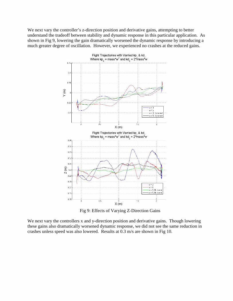
We next vary the controller’s z-direction position and derivative gains, attempting to better understand the tradeoff between stability and dynamic response in this particular application. As shown in Fig 9, lowering the gain dramatically worsened the dynamic response by introducing a much greater degree of oscillation. However, we experienced no crashes at the reduced gains.
We next vary the controllers x and y-direction position and derivative gains. Though lowering these gains also dramatically worsened dynamic response, we did not see the same reduction in crashes unless speed was also lowered. Results at 0.3 m/s are shown in Fig 10.
Fig 9: Effects of Varying Z-Direction Gains

Fig 10: Effects of Varying XY-Direction Gains
Fig 11: Flight Test in Progress

7. CONCLUSION AND FUTURE WORK In this paper, we refine the rotor aerodynamics model for the Nano quadrotor, simulate its flight in a constrained environment using this more accurate model, design an actual environment in which we can conduct test flights, and present the data from several of these tests. Our model fits well both experimental data for rotor aerodynamics and flight data for surface effects. For the former, it succeeds in further refining the model improvement proposed in [1], and for the latter, it more usefully implements the data from [1]. The simulation based on this model is a more qualified success. Its general shape mostly matches the results of actual flight tests. Compared to the control trajectory, surface effects result in greater heights during takeoff and while flying through the tunnel, and relative velocity results in lesser heights during forward flight towards the tunnel. It also successfully shows a sudden change in the thrust force as the quadrotor enters and exits the tunnel. However, it underestimates the seriousness of this change, demonstrating the controller easily compensating for it and never crashing. The tunnel environment has been successfully constructed and will be useful for future work. However, the frequency of crashes in early test flights demonstrate the greater than expected seriousness of the incorrect rotor aerodynamics. The early data suggests a combination of reduced speed and reduced z-direction controller gains can eliminate the most serious of the problems caused by the tunnel. However, more will be needed to make the trajectory as straight as the trajectory without the tunnel. Future work will focus on the necessary control refinement. We suggest inverting the presented model for compensated control and attempting to better tune controller gains, perhaps intelligently varying these as the quadrotor enters and exits the tunnel. Future research is also needed in the use of an alternative to Vicon data for sensing aerodynamic conditions. One such alternative could be pressure data from a barometer already included in the Nano quadrotor. 8. ACKNOWLEDGEMENTS I would like to thank my adviser, Dr. Vijay Kumar, for enabling me to conduct this research in the GRASP quadrotor laboratory at the University of Pennsylvania. I would also like to thank my mentor, Caitlin Powers, for her invaluable advice throughout the project. Thanks as well to the other members of the laboratory, especially Daniel Mellinger, for their unaccredited yet vital assistance. This research was made possible by the SUNFEST program, a Research Experience for Undergraduates (REU) grant funded by the National Science Foundation and facilitated by the University of Pennsylvania. 9. REFERENCES 1. C. Powers, D. Mellinger, A Kushleyev, B. Kothmann, V. Kumar. Influence of aerodynamics
and proximity effects in quadrotor flight. June. University of Pennsylvania Working Papers in Mechanical Engineering.

2. N. Michael, D. Mellinger, Q. Lindsey, and V. Kumar. The grasp multiple micro-uav testbed. Robotics Automation Magazine, IEEE, 17(3):56 –65, 2010.
3. A. Kushleyev, D. Mellinger, and V. Kumar. Towards A Swarm of Agile Micro Quadrotors. Robotics: Science and Systems, July 2012.
4. D. Mellinger, N. Michael, V. Kumar. Trajectory Generation and Control for Precise Aggressive Maneuvers with Quadrotors. Int. Symposium on Experimental Robotics, Dec 2010.
5. D. Pines and F. Bohorquez, “Challenges facing future micro air vehicle development,” AIAA Journal of Aircraft, vol. 43, no. 2, pp. 290–305, 2006.
6. Haomiao Huang, G.M. Hoffmann, S.L. Waslander, and C.J. Tomlin. Aerodynamics and control of autonomous quadrotor helicopters in aggressive maneuvering. Robotics and Automation, 2009. ICRA ’09. IEEE International Conference, pp. 3277 –3282, May 2009.
7. KMel Robotics. http://www.kmelrobotics.com. 8. Vicon Motion Systems, Inc. http://www.vicon.com. 9. W. Johnson. Helicopter Theory. Princeton University Press, Princeton, NJ, 1980.