precision flight control for a multi-vehicle quadrotor...
TRANSCRIPT

Precision Flight Control for A Multi-Vehicle Quadrotor Helicopter Testbed
Gabriel M. Hoffmanna,1, Haomiao Huanga,1, Steven L. Waslanderb,1, Claire J. Tomlinc
a Aeronautics & AstronauticsStanford UniversityStanford, CA 94305
[email protected], [email protected] Department of Mechanical and Mechatronics Engineering
University of WaterlooWaterloo, ON, Canada, N2L 3G1
[email protected] Electrical Engineering and Computer Sciences
University of California BerkeleyBerkeley, CA 94708
Abstract
Quadrotor helicopters continue to grow in popularity for unmanned aerial vehicle applications. However, accuratedynamic models for deriving controllers for moderate to high speeds have been lacking. This work presents theoreticalmodels of quadrotor aerodynamics with non-zero free-stream velocities based on helicopter momentum and bladeelement theory, valianced with static tests and flight data. Controllers are derived using these models and implementedon the Stanford Testbed of Autonomous Rotorcraft for Multi-Agent Control (STARMAC), demonstrating significantimprovements over existing methods. The design of the STARMAC platform is described, and flight results arepresented demonstrating improved accuracy over commercially available quadrotors.
Keywords: quadrotor helicopters, unmanned aerial vehicles, flight control, quadrotor aerodynamics
1. Introduction
Quadrotor helicopters are an increasingly popular rotorcraft concept for unmanned aerial vehicle (UAV) platforms.These vehicles use two pairs of counter-rotating, fixed-pitch rotors located at the four corners of the aircraft, as shownin Figure 1. Their use as autonomous platforms has been envisaged in a variety of applications, both as individualvehicles and in multiple vehicle teams, including surveillance, search and rescue, and mobile sensor networks [1].
Recent interest in the quadrotor design from numerous communities, including research, surveillance, constructionand police use [2], can be linked to two main advantages over comparable vertical take off and landing (VTOL) UAVs,such as helicopters. First, quadrotors can use fixed pitch rotors and direct control of motor speeds for vehicle control,simplifying design and maintenance by eliminating complex mechanical control linkages for rotor actuation. Second,the use of four rotors ensures that individual rotors are smaller than the equivalent main rotor on a helicopter for agiven airframe size. The smaller rotors store less kinetic energy during flight and can be enclosed within a protectiveframe, permitting flights indoors and in obstacle-dense environments with reduced risk of damage to the vehicles,their operators, or surroundings. These added safety benefits greatly accelerate the design and test flight process byallowing testing to take place indoors or out, by inexperienced pilots, and with a short turnaround time for recoveryfrom incidents.
As a result of these advantages, there have been a number of commercial [3, 4, 5, 6] and research [7, 8, 9, 10]quadrotor platforms developed. However, there has been relatively little development of accurate dynamics modelsof quadrotors for operating at higher speeds and in outdoor environments. Such models and control techniques based
1These authors contributed equally to this work.
Preprint submitted to Control Engineering Practice April 7, 2011

Figure 1: STARMAC II quadrotor helicopter.
upon the models are critical for precision control and trajectory tracking. The main contributions of this work arethe presentation of aerodynamic models for quadrotors and the use of these models in the development of a quadro-tor platform (the Stanford Testbed of Autonomous Rotorcraft for Multi-Agent Control, or STARMAC) capable ofachieving the sub-meter positioning precision necessary to fly multiple vehicles in a confined area with substantialmotion.
STARMAC has been developed to take advantage of the benefits of quadrotors, with the aim of being an easy-to-use and reconfigurable proving ground for novel algorithms for multi-agent applications. It is currently comprised ofsix STARMAC II quadrotors. These vehicles have been used to demonstrate a variety of algorithms, including ex-periments for collision avoidance [11, 12], information-theoretic control for cooperative search [13, 14], dynamicallyfeasible trajectory generation[15, 16], and verification of provably safe aerobatic maneuvers[17]. In each case, theflexibility and convenience of the quadrotor design in general and the precision flight capabilities of STARMAC inparticular have enabled rapid evaluation of new technologies.
In this work, aerodynamic models of quadrotor helicopters are developed, based on well established researchfor helicopter aerodynamics [18, 19, 20], including the effects of angle of attack and speed on total thrust, and theeffect of blade flapping on the direction of thrust and moments acting on the vehicle. The models are valiancedwith static thrust test stand measurements and incorporated into a nonlinear simulation to compare with flight testresults. Second, the models are used to derive nonlinear control laws to counteract the effects of a non-zero free-stream velocity on the quadrotor vehicle in flight. Variations in thrust due to angle of attack and speed are eliminatedthrough feedforward thrust variation, while blade flapping moments are countered through feedforward differentialthrust commands. Finally, a comprehensive set of controller designs are proposed for closed loop attitude, altitude,position and trajectory tracking that enable precise execution of the desired path, and are demonstrated in both indoorand outdoor flight test results. Given precise state estimation and aerodynamic modeling, simple control laws producethe desired control precision. Although the models and controls are developed and tested on the STARMAC platform,the results are applicable to the design and control of any general quadrotor helicopter.
The paper proceeds as follows. Section 2 presents a summary of the history of quadrotors and a review of relatedwork. Then, in Section 3 a nonlinear dynamic model of the quadrotor helicopter is developed, with focus on the effectsof vehicle motion on the forces and moments produced by the vehicle. The design choices made for STARMAC II arepresented in Section 4, including propulsion, frame, sensors, communications, and computational payloads. Finally,the control system design is described in Section 5, with flight test results for each control loop culminating in multiplewaypoint trajectory tracking demonstrations with sub-meter accuracy.
2. Related Work
Quadrotor helicopters are controlled by varying the thrust of two sets of counter-rotating rotor pairs, as depictedin Figure 2. Pitch and roll angles are controlled using moments generated by differential thrust between rotors onopposite sides of the vehicle, and the yaw angle is controlled using the difference in reaction torques between thepitch and roll rotor pairs. Vertical position is controlled with the total thrust of all rotors, and lateral acceleration iscontrolled through the pitch and roll of the aircraft.
2

(a) (b)
Figure 2: Quadrotor helicopters are controlled by varying thrust at each rotor to produce (a) roll or pitch axis torques, and (b) yaw axis torque.
The first flight-capable quadrotor designs appeared as early as the 1920’s [19], though no practical versions werebuilt until more recent advances in microprocessor capabilities and in micro-electro-mechanical system (MEMS)inertial sensors have allowed for automatic stability augmentation systems. These advances have spawned a seriesof new quadrotor designs, from simple remote control (RC) quadrotor toys such as the Roswell flyer (HMX-4) [21],and Draganflyer [22] to more advanced autonomous aerial vehicles capable of waypoint trajectories and autonomousaerial surveillance tasks.
Increased interest in small quadrotors led to the development of numerous commercially available platforms withautonomous flight capabilities. The MD4-200 quadrocopter from Microdrones GmbH [3], available in 2006, Dragan-fly X4 [5] and Aeryon Scout [6], both available in 2009, are capable of GPS waypoint tracking. The Hummingbirdand Pelican from Ascending Technologies are similarly capable. The estimation and control for these vehicles usesingle-frequency GPS, with accuracy of 5 m circular error precision (CEP), resulting in position control errors ofsimilar magnitude (demonstrated 5-10 m error depending on wind conditions for the Aeryon Scout and 3-5m forthe Pelican, estimated for other platforms). These systems are intended for open spaces, low speed operations, andmoderate wind conditions.
For autonomous operation in cluttered environments through accurate trajectory control, work on the OS4 quadro-tor [23] identified several dynamic effects beyond the rigid body equations of motion, including gyroscopic torque,angular acceleration of blades, drag force on the vehicle, and rotor blade flapping. Back-stepping control was used toimprove on the vehicle’s initial linear control law and reduce position control errors. Similarly, the X-4 project at theAustralian National University [24] considered the effects of blade flapping, roll and pitch damping due to differingrelative ascent rates of opposite rotors, and rotor design, and showed preliminary results considering these effects forvehicle and rotor design in flight tests [25, 26].
Recent research in quadrotor design focuses on extending these capabilities for more complex missions [27, 21,23, 28, 29, 30, 31, 25, 32, 8, 9, 10, 33] with more demanding system requirements. The range of projects resulted invehicles from 0.3 to 4.0 kg, and demonstrate a variety of designs and control techniques that seek to extend vehiclecapabilities to more complex tasks. Specifically, the STARMAC platform[27] was developed with the dual aimsof enabling autonomous operation in constrained environments as well as allowing multiple vehicles to operate inclose proximity for team missions that benefit from multiple simultaneous viewpoints. The combination of these twocapabilities opens the door to many new applications.
One important emerging application area is the focus on convenient indoor quadrotor testbeds, with similarly strin-gent positioning requirements for safe operation in close proximity to obstacles in the environment, though mostlyoperating at low speeds. The SWARM project [7] focuses on multi-vehicle coordination and demonstrated impressivemulti-vehicle trajectory tracking control using Draganflyer V Ti Pro quadrotors with LQR control. Sensing and com-putation occur off-board on a centralized platform using the Vicon positioning system indoors at low speeds. Morerecent efforts have developed a vehicle capable of autonomous indoor exploration using a laser scanner and stereo vi-sion [8], which performs computation off board as well. The GRASP lab has shown results with a group of quadrotorscarrying out coordinated flights for carrying a single load with multiple vehicles [9]. Finally, an indoor flight systemhas been developed successfully demonstrating certain extreme flight maneuvers in a controlled environment [10].Both of these last efforts use the Vicon positioning system and off-board state estimation.
3

The precision flight capability of existing designs intended for outdoor flight, both commercial and academic, aretypically insufficient for operation with any significant speed in constrained environments. Also, while many researchplatforms have demonstrated advanced capabilities in controlled, indoor environments with off-board computation,very few have been developed for self-sufficient autonomous multi-vehicle operation. The work presented in thispaper focuses on a novel quadrotor helicopter design that is capable of flying both indoors and outdoors at significantspeeds, and can carry sufficient sensing and computing resources not only to localize and control the aircraft, but alsoto enable higher levels of vehicular autonomy. Some preliminary versions of these results were presented in [34, 35].
3. Vehicle Aerodynamics
A detailed development of the aerodynamics of quadrotor helicopters is now presented. First, the vehicle’s fullnonlinear dynamics are presented. Then, the vehicle’s input forces and moments are computed for non-zero free-stream velocities based on techniques from helicopter analysis. These inputs are used in the development of vehiclecontrollers in Section 5.
3.1. Inertial DynamicsThe derivation of the nonlinear dynamics is performed in North-East-Down (NED) inertial and body fixed coordi-
nates. Let eN , eE , eD denote unit vectors along the respective inertial axes, and xB, yB, zB denote unit vectors alongthe respective body axes, as shown in Figure 3. Euler angles to rotate from NED axes to body fixed axes are the 3-2-1sequence ψ, θ, φ, referred to as yaw, pitch, and roll, respectively. The current velocity direction unit vector is ev, ininertial coordinates. The direction of the projection of ev onto the xB − yB plane defines the direction of elon in thebody-fixed longitudinal, lateral, vertical frame, elon, elat, ever, as shown in Figure 8. Due to blade flapping, the rotorplane does not necessarily align with the xB, yB plane, so for the jth rotor let xR j , yR j , zR j denote unit vectors alignedwith the plane of the rotor and oriented with respect to the elon, elat, ever frame. Let x be defined as the position vectorfrom the inertial origin to the vehicle c.g., and let ωB be defined as the angular velocity of the aircraft in the bodyframe.
Figure 3: Free body diagram of a quadrotor helicopter.
The rotors, numbered 1 − 4, are mounted outboard on the xB, yB, −xB and −yB axes, respectively, with positionvectors r j with respect to the c.g. The thrust T j produced by the jth rotor acts perpendicularly to the rotor plane alongthe zR j axis, as defined in Figure 4. The vehicle body drag force is Db ∝ v2
∞, vehicle mass is m, acceleration due togravity is g, and the inertia matrix is IB ∈ R3×3. A free body diagram is depicted in Figure 3, with a depiction of therotor forces and moments in Figure 4. The total force, F, can be summed as,
F = −Dbev + mgeD +
4∑j=1
(−T jRR j,IzR j
)(1)
4

Figure 4: Free body diagram of the moments and forces acting on rotor j.
where RR j,I is the rotation matrix from the plane of rotor j to inertial coordinates. Similarly, the total moment, M, is,
M =
4∑j=1
(M j + Mb f , j + r j × (−T jRR j,BzR j )
)(2)
where RR j,B is the rotation matrix from the plane of rotor j to body coordinates. Note that the drag force was neglectedin computing the moment. This force was found to cause a negligible disturbance on the total moment over the flightregime of interest, relative to blade flapping torques. The full nonlinear dynamics can be described as,
F = mx (3)M = IBωB + ωB × IBωB (4)
where the total angular momentum of the rotors is assumed to be near zero, as the momentum from the counter-rotatingpairs cancels when yaw is held steady.
3.2. Aerodynamic Forces and Moments
Although quadrotor helicopter dynamics are often modeled as independent of free-stream velocity for attitude andaltitude control, this assumption is only reasonable at low velocities. Even at moderate velocities, the impact of theaerodynamic effects resulting from variation in air speed is significant.
Two main effects are presented here that have each been experimentally observed on the STARMAC platform.The first effect is the variation in total thrust from a rotor with free-stream velocity and angle of attack, and the secondis the effect known as “blade flapping”, resulting from the differing flow velocities experienced by advancing andretreating blades of a rotor in translational flight. Aerodynamic drag, a reaction force proportional to speed squared,will not be discussed because it is both vehicle design-dependent and already well known. At moderate speeds,both experimental results and the literature [19] show that the effect of drag on rotorcraft is less significant than thefollowing more dominant effects.
3.2.1. Total ThrustThrust is produced by each rotor through the torque applied the rotor by a motor. The thrust can be analyzed by
equating the power produced by the motors to the ideal power required to generate thrust by changing the momentumof a column of air. At hover, the ideal power, Ph, is
Ph = Tvh (5)
where the induced velocity at hover, vh, is the change in air speed induced by the rotor blades with respect to thefree-stream velocity, v∞.
5

Flight Speed (m/s)
Ang
le o
f Atta
ck (
deg)
(T/Th)P=const
for vh=6 m/s
1 2 3 4 5 6−20
−15
−10
−5
0
5
10
15
20
1
1.1
1.2
1.3
1.4
1.5
1.6
1.7
Figure 5: Thrust dependence on angle of attack and vehicle speed.
As a rotorcraft undergoes translational motion or changes its angle of attack, the induced power, the power trans-ferred to the free-stream, changes. To derive the effect of free-stream velocity on induced power from conservation ofmomentum, the induced velocity vi of the free-stream by the rotors of an ideal vehicle can be found by solving [19]
vi =v2
h√(v∞ cosα)2 + (vi − v∞ sinα)2
(6)
for vi, where α is the angle of attack of the rotor plane with respect to the free-stream, with the convention that positivevalues correspond to pitching up (as with airfoils). The physical (non-imaginary) solution to this equation is accurateover a wide range of flight conditions as shown by experimental results in the literature [36], especially at smallangles of attack. At large angles of attack, the rotor can enter the vortex ring state, at which point the equation nolonger holds, as will be described below. Nonetheless, it provides an accurate result for much of the flight envelope,including portions of the flight envelope for which momentum theory is not applicable. Using the expression for vi,or a numerical solution, the ideal thrust T for power input P can be computed, using
T =P
vi − v∞ sinα(7)
where the denominator is the air speed across the rotors.For electric motors, the power applied by each motor varies proportional to the square of the applied voltage [34],
thus for a given commanded voltage and related nominal thrust the actual thrust generated varies depending on thetranslational velocity. The value of the ratio of thrust to hover thrust, T/Th, is plotted for the vh of STARMAC II inFigure 6. At low speeds the angle of attack has vanishingly little effect on T/Th. However, as speed increases T/Th
becomes increasingly sensitive to the angle of attack, varying by a substantial fraction of the aircraft’s capabilities.Similar to an airplane, pitching up increases the lift force. The angle of attack for which T = Th increases withforward speed. For level flight, the power required to retain altitude decreases with the forward speed. However, tomaintain speed in level flight, the vehicle must pitch forward more as speed increases to cancel drag, leading to a needfor more thrust to maintain altitude. There is an optimum speed for any rotorcraft, greater than zero, at which powerto stay aloft is minimized (a reduction from power needs in hover of up to 30% or more) [19]. This speed varies withaircraft configuration.
In the extreme regions of angle of attack close to vertical flight, rotorcraft have three operational modes dependingon the vehicle’s climb velocity vc, two of which are solutions to Eq. (6) (where cosα = 0), and one of which is a
6

recirculation effect that invalidates the assumptions for conservation of momentum [19]. Note that these three modesencompass vertical ascent or descent, and are therefore often encountered. The three modes are defined as follows:
1. Normal working state: 0 ≤ vcvh
2. Vortex ring state (VRS): −2 ≤ vcvh< 0
3. Windmill brake state: vcvh< −2
In normal working state air flows down through the rotor, and in windmill brake state air flows up through therotor due to rapid descent. In both cases, conservation of momentum can be used to derive the induced velocity. Forthe normal working state, encompassing hover and ascent conditions, the induced velocity is
vi = −vc
2+
√(vc
2
)2+ v2
h (8)
For the windmill braking state, the induced velocity is,
vi = −vc
2−
√(vc
2
)2− v2
h (9)
In the vortex ring state, air recirculates through the blades in a periodic and somewhat random fashion. As a result,the induced velocity varies greatly, particularly over the domain −1.4 ≥ vc/vh ≥ −0.4, causing rapid random variationin the thrust [36]. An empirical model [19] of induced velocity in vortex ring state is
vi = vh
κ + k1
(vc
vh
)+ k2
(vc
vh
)2
+ k3
(vc
vh
)3
+ k4
(vc
vh
)4 (10)
where k1 = −1.125, k2 = −1.372, k3 = −1.718, k4 = −0.655, and κ is the measured induced power factor in hover,with a typical value of around 1.15 [19]. This model compares with the mean of experimental results in the literature,though it fails to capture the periodic nature of vortex entrapment.
To model the dynamics during climb, the power is the thrust times the speed it is applied at, hence
T =P
vc + vi(11)
ignoring profile power (drag) losses. Note that Tvc is the power consumed by the climbing motion, whereas Tvi is theinduced power transferred into the air. It is typically desirable to avoid the vortex ring state, which can be done bymaintaining a substantial forward speed while descending [18].
The thrust achieved for a given input power, ignoring profile power losses, can be computed as a function of climbvelocity by substituting Eqs. (8), (9), and (10) into Eq. (11). For typical flight conditions experienced by STARMACII, the ratio of the thrust to hover thrust at a constant power input is shown in Figure 6, for both the theoretical curve,using the solution to the above equations, and experimental data from a thrust measurement stand using a verticalwind disturbance. As is visible in Figure 6, there is a clear loss of thrust associated with climbing, reducing linearlywith climb velocity. Finally, a significant negative climb velocity results in an increase in resulting thrust. In thrusttest stand experiments, the loss of thrust with an applied climb velocity was clearly noted. The descent velocityexperiments were less conclusive. The descent speeds available with the test apparatus were less than those requiredfor full vortex ring state, though vibration was observed, indicating that unsteady flow did occur.
The effect of angle of attack on the total thrust generated by STARMAC II was consistently observed in flighttests, as shown in Figure 7a, where an earlier generation PID control law is used to control altitude. When the vehicleundergoes a quick roll motion increasing the angle of attack, the thrust increases rapidly, acting as a disturbance onthe control system. This reaction is predicted by the equations of motion presented in this section, as shown in afull vehicle simulation in Figure 7b. In Section 5, a control law is presented that is more capable of rejecting thesedisturbances, with feedback control of total thrust.
7

−3 −2 −1 0 1 20.7
0.8
0.9
1
1.1
1.2
1.3
1.4
Velocity (m/s)
T/Th
PredictedMeasured
Figure 6: Predicted ideal thrust and measured climb thrust with vertical velocity.
3.2.2. Blade FlappingThe second aerodynamic effect to have a significant impact on the dynamics of quadrotor helicopters is blade
flapping. In translational flight, the advancing blade of a rotor has a higher velocity relative to the air, while theretreating blade has a lower velocity, resulting in a variation in lift that causes the rotor blades to flap up and down [20].This flapping of the blades tilts the rotor plane back from the direction of motion, resulting in a variety of effects onthe dynamics of the vehicle, and in particular affecting attitude control performance [25]. For this subsection, theeffects on an individual rotor will be considered, so for readability the rotor index, subscript j, is omitted.
The flap angle β of a rotor blade is typically defined in the helicopter literature as the total deflection of a rotorblade away from horizontal in body coordinates at any point in the rotation, and is calculated as
β = a0s − a1s cos Ψ + b1s sin Ψ (12)
where a0s is the blade deflection due to coning, a1s and b1s are the longitudinal and lateral blade deflection angles,respectively, due to flapping. The azimuth angle of the blade Ψ is defined to be zero in the direction opposite horizontalvelocity of the rotor. The longitudinal deflection gives the amplitude of the rotor tilt when Ψ = (0, π) rad, and thelateral deflection is the amplitude when Ψ = (π/2, 3π/2) rad.
The blade flapping properties of a rotor can differ significantly depending on whether or not the rotor blades arehinged at the base. The equation for deflection angle of a flapping rotor with hinged blades is [25]
a1s =1
1 +µ2
lon2
43
(CT
σ
23µlonγ
a0+ µlon
)(13)
where a0 is the slope of the lift curve per radian (typically about 6.0 for conventional airfoils at low Mach num-bers [20]). The longitudinal rotor advance ratio, µlon = vlon
vt, is the ratio of longitudinal speed to blade tip speed,
vt = ΩR. The nondimensional Lock number, γ = ρa0cR4/Ib, is the ratio of aerodynamic to centrifugal forces, whereIb is the moment of inertia of the blade about the hinge, c is the chord of the blade, and R is the rotor radius. Finally,σ = Ab/A is the solidity ratio of the rotor, where Ab is the total area of the rotor blades. The non-dimensionalizedtorque coefficient is CT .
The flapping properties of a stiff, fixed-pitch rotor blade, as used on STARMAC II and more typically found onmost quadrotors, can be analyzed by modeling the blade as being hinged at an effective offset e f from the center ofrotation (expressed as a percentage of the rotor radius) and a torsional spring with stiffness kβ Nm/rad at the hinge [18].This approximates the first bending mode of the blade and is sufficient for the small deflection angles of interest. Bothe f and kβ can be determined by measuring the natural frequency ωn of blade vibration [20, 18]. With these parameters,the equilibrium flapping angles can be determined by solving [18]
8

20 21 22 23 24 25
0
20
40
Rol
l (de
g)
20 21 22 23 24 250
0.5
1
Alti
tude
(m)
20 21 22 23 24 25
−2
0
2
Time (sec)
Eas
t Vel
ocity
(m/s
)
ActualCommanded
ActualCommanded
0 1 2 3 4 5 6−20
0
20
Rol
l (de
g)
ActualCommanded
0 1 2 3 4 5 6−5
0
5
Eas
t Vel
ocity
(m
/s) 0 1 2 3 4 5 6
−0.5
0
0.5
Alti
tude
(m
)
ActualCommanded
(a) (b)
Figure 7: Effect of angle of attack on altitude control, (a) in a flight test using an earlier generation PID controller, and (b) in simulation using theinduced power equations.
Figure 8: Blade flapping with stiff rotor blades modeled as hinged blades with offset and spring.
λ2β 0 0 0
γ6µlon (1 − λ2
β) −γ8 0
0 γ8 (1 − λ2
β) 00 0 0 1
a0s
a1s
b1sCTσa0
=
γ8 −
γ6
0 0γ3µlon 0
13 − 1
2
[
Θavg
µver + λi
](14)
where the induced inflow ratio λi = vivt
. The vertical advance ratio is µver =vvervt
. The average pitch angle of theblade is Θavg. λβ is the ratio of the flapping frequency ωβ to the angular rate Ω of the rotor, and can be calculated foruse in Eq. (14) as
λβ =
√(1 +
32
e f ) +kβ
IbΩ2 (15)
Blade flapping causes both longitudinal and lateral thrust forces and moments. For quadrotor helicopters, however,the moments generated by lateral deflections cancel when yaw rates are low relative to airspeed, and generation ofunbalanced moments is due entirely to the longitudinal deflection, a1s. The backward tilt of the rotor plane generateslongitudinal thrust Tlon (see Figure 8),
Tb,lon = T sin a1s (16)
If the center of gravity (c.g.) is not vertically aligned with the rotor plane, this longitudinal force will generate a
9

2 4 6 8
145
150
155
160
165
170
175
time (s)
Mea
sure
d H
oriz
onta
l For
ce (
gram
s fo
rce)
0 m/s0.6 m/s1.1 m/s1.5 m/s1.8 m/s2.5 m/s3.4 m/s
0 1 2 3 40
1
2
3
4
5
Wind Velocity (m/s)
Def
lect
ion
Ang
le a
1s (
deg)
measuredpredicted (stiff blades)predicted (hinged blades)
(a) (b)
Figure 9: (a) Horizontal force measurements at different wind speeds to calculate the flapping angles. (b) The measured deflection angle comparedwith predicted values for hinged, freely flapping blades and for stiff, unhinged blades.
moment about the c.g., Mb,lon = Tb,lonzcg, where zcg is the vertical distance from the rotor plane to the c.g. of thevehicle. For stiff rotors, as are used in most current quadrotor helicopters, the tilt of the blades also generates amoment at the rotor hub
Mb,s = kβa1s (17)
where kβ is the stiffness of the rotor blade in Nm/rad. Finally, Mb f = Mb,lon + Mb,s is the total longitudinal momentcreated by blade flapping.
To validate the models developed for blade flapping on the STARMAC platform, the thrust test stand was used.The lateral force due to the deflection of the thrust vector by flapping was measured for a single rotor by blowing airat fixed velocities across a spinning rotor attached to the test stand. This data was filtered and used to calculate theaverage deflection angle as a function of incident wind velocity and compared to the model predictions. Equation (13)predicts a roughly linear relationship between velocity and deflection angle in the shown operating regime. In practice,this equation over-predicts the flapping seen by rotors with non-hinged blades where the stiffness of the blades mustbe taken into consideration, as in the model presented in Eq. (14). For the flapping equations, ωn was also measuredusing the test stand, giving an effective hinge offset of 25% for the Wattage 10 × 4.5 rotors. The value for kβ wasmeasured to be 0.23Nm/rad.
The results, plotted in Figure 9, clearly indicate that the non-hinged blade flapping model accurately captures theeffect of free-stream velocity on the angle of the rotor plane. Note that turbulence caused oscillations in the bladedeflection during experiments, so the measurements presented are an average deflection over a period of 20 s.
The effect of blade flapping was consistently observed in flight tests as shown in Figure 10a, where an aircraftcontrolled by a simple PD control law is disturbed by the moment due to blade flapping, an effect that increaseswith speed. The equations of motion in this section predict this effect on the control system, as shown in a fullsimulation of the dynamics in Figure 10b. In Section 5, a control law is presented that is more capable of rejectingthese disturbances, actively rejecting discrepancies between desired and actual torques.
The design of the STARMAC quadrotor platform used for model validation and control design is now brieflypresented.
4. Design
The first generation vehicle, STARMAC I, was developed from 2003 to 2005 [27, 37]. It was based on theDraganflyer III [22] platform and was envisaged as a lightweight, easy-to-use testbed for multi-vehicle operations.The vehicles were capable of autonomous hover when coupled with off-board state estimation, however limitations inpayload, communications, and computation impaired their ability to perform on-board testing of autonomous multi-agent algorithms. As a result of these limitations, STARMAC II was developed to address the following requirements:
10

45 45.5 46 46.5 47 47.5 48 48.5 490
10
20
30
Pitc
h (
deg)
ActualCommanded
45 45.5 46 46.5 47 47.5 48 48.5 49
0
2
4
Time (s)
Vel
ocity
(m
/s)
0 2 4 6 8 10 120
10
20
30
Pitc
h (d
eg)
0 2 4 6 8 10 120
5
10
15
20
Vel
ocity
(m
/s)
Time (s)
(a) (b)
Figure 10: Effect of blade flapping on pitch control, (a) in a flight test using an earlier generation PD controller and (b) in simulation using theblade flapping equations.
1. Safe, simple operation both indoors and outdoors.2. Onboard autonomous position control and trajectory tracking.3. Onboard perception of the environment through a variety of sensors.4. Onboard implementation of multi-vehicle coordination algorithms.
The first requirement drove the selection of the quadrotor helicopter as a safe, easy to use platform with limitedmaintenance requirements. The ability to hover was deemed essential for operation in confined spaces. The secondand third requirements drove the selection of the sensor suite to be included on board the vehicles, that in turn drovethe payload requirements. The fourth requirement drove the need for a broadband communication device and theinclusion of significant computational power. There was a tradeoff between keeping the vehicle small enough toeasily ensure safety, and making it large enough to support the payload necessary for the applications envisaged for it.
4.1. Vehicle Design
The vehicle frame, shown in Figures 1 and 11, was designed to be as light as possible, while maintaining sufficientstiffness to ensure accurate state measurement and control actuation. The core of the vehicle uses fiberglass laminatedhoneycomb plates to mount and protect the electronics and provide structural rigidity, and can be vertically expandedto accommodate payloads. The remainder of the frame is carbon fiber tubes and tube straps. This design allows thevehicle to be easily reconfigured for different experiments and payloads. Also, when a collision of sufficient strengthoccurs, the tubes have some ability to slide in the tube straps rather than breaking, and the tube straps themselves canflex to absorb energy.
The propulsion system was designed for safety and efficiency. The design goal was to maximize flight time andpayload capacity, while remaining small and controllable enough to fly in confined indoor environments. The desiredpayload capacity was a minimum of 0.4 kg for enhanced on-board computation, with 1.0 kg enabling the inclusion ofa suite of environment sensors for autonomous operation in unknown surroundings.
The control electronics are comprised of an electronics interface board and several processors. Computationoccurs in two stages. The low level processing controls the attitude and altitude dynamics at a fast rate, and the highlevel processing manages longer computations and position control at a slower rate. The low level computing occurson an Atmega128 microprocessor that uses measurements from the IMU and ultrasonic rangefinder to control vehicleattitude and altitude at 76 Hz. The high level processing occurs on either a Gumstix Verdex single board computer(SBC) [38] running embedded Linux on a PXA270 microprocessor, or on an Advanced Digital Logic PC104 [39]running Fedora Linux for applications requiring greater computation power. A common program was written for bothaircraft configurations that manages control and sensing in real-time.
11

UltrasonicRanger
SenscompMini-AE
UltrasonicRanger
SenscompMini-AE
Inertial Meas. UnitMicrostrain3DM-GX1
Inertial Meas. UnitMicrostrain3DM-GX1
GPSNovatel
Superstar II
GPSNovatel
Superstar II
Low Level ControlRobostix Atmega128Low Level Control
Robostix Atmega128
Carbon Fiber Tubing
Carbon Fiber Tubing
Fiberglass HoneycombFiberglass
Honeycomb
Tube StrapsTube
Straps
SensorlessBrushless DC MotorsAxi 2208/26
SensorlessBrushless DC MotorsAxi 2208/26
Elect. Speed Cont.Castle Creations
Phoenix-25
Elect. Speed Cont.Castle Creations
Phoenix-25
BatteryLithium Polymer
BatteryLithium Polymer
High Level ControlGumstix PXA270,
or ADL PC104
High Level ControlGumstix PXA270,
or ADL PC104
Landing Gear
Landing Gear
Electronics Interface
Electronics Interface
Figure 11: STARMAC II vehicle and its components.
4.2. SensorsThe sensor suite is comprised of two categories of sensors–those used to estimate the vehicle state and those used
to perceive the surrounding environment. Measurements from the vehicle state sensors are used for attitude, position,and path tracking control algorithms, as will be described in Section 5. The sensors for the surrounding environmentwill be used for automated search and rescue, obstacle detection, and simultaneous localization and mapping.
The vehicle is equipped with three sensors for vehicle state estimation, all of which are fused using an ExtendedKalman Filter (EKF). Measurements are fused from a Microstrain 3DM-GX1 inertial measurement unit (IMU), adownward facing Senscomp Mini-AE ultrasonic rangefinder, and integrated carrier phase (ICP) measurements froma Novatel Superstar II GPS receiver. For the GPS, a custom code was developed in house, providing 10 Hz positionand velocity estimates with an accuracy of 0.02-0.05 m relative to a stationary base station. The code is executed inthe background in real-time on existing on-board computers. For indoor flights, an overhead USB camera was usedin conjunction with hue blob tracking software to provide position sensing in place of GPS for the flights presentedin this paper. The camera system gives 0.01-0.02 m accuracy at 15 Hz, and combined with ultrasonic measurementsof the range to the floor, provides a drop-in replacement for GPS input to the EKF. The camera system has beensubsequently replaced with a VICON position-tracking system.
To perceive the surrounding environment, the vehicle frame can be reconfigured to carry additional sensors forspecific applications. Numerous additional sensors have been tested on the STARMAC platform, including the VidereSystems stereo vision camera [40], various USB cameras, the Hokuyo URG-04LX laser range finder [41], and theTracker DTS digital avalanche rescue beacon and receiver [42]. These sensors were selected to enable potentialautonomous multi-agent missions, such as cooperative search and rescue [1].
5. Control System
A hierarchical approach to vehicle control was adopted for STARMAC II. This section gives the results of thiscontrols development process in order from the inner attitude and altitude loops to the position and trajectory trackingloops. A feedforward compensator adjusts for the aerodynamic effects discussed in Section 3.
5.1. Attitude and Altitude ControlAt small angles (roughly ±30), the equations of motion are approximately decoupled about each attitude axis, so
control input moments about each axis, uφ, uθ, and uψ, can be implemented independently. The inputs for each axis
12
are added to the total thrust control input uz to generate thrust commands u1 through u4, for motors 1 through 4,
u1 = uθ/L + uψ/(4κt) + uz/4u2 = −uφ/L − uψ/(4κt) + uz/4u3 = −uθ/L + uψ/(4κt) + uz/4u4 = uφ/L − uψ/(4κt) + uz/4
(18)
where L is the distance between rotor centers and the zB axis. The time delay in thrust is well approximated as afirst order delay with time constant τ, as experimentally verified [34], and found to be 0.1 s for STARMAC II. Theresulting transfer function for the roll axis is
Φ(s)Uφ(s)
=1/Iφ
s2(τs + 1)(19)
where Iφ is the component of IB for the roll axis. The transfer functions for the pitch and yaw axes are analogous.Note that the induced power and blade flapping effects are not included in the linear model; they are compensatedusing feed forward compensation described in Section 5.2. Any inaccuracies in this model or complications such asvortex ring state are treated as disturbance forces and moments that must be rejected by the control system.
Although a standard proportional-integral-derivative (PID) controller has been shown to perform adequately [37],control design using root locus techniques revealed that an additional zero, giving angular acceleration feedback,allowed the gains to be significantly increased, yielding higher bandwidth. Further, acceleration compensation givesdirect feedback on the actual thrust achieved, regardless of vortex ring state or ascent/descent dynamics of Section 3-3.2. The resulting control law,
C(s) = kdd s2 + kd s + kp +ki
s(20)
was tuned to provide substantially faster and more accurate performance than previously possible for maneuveringvehicles (see Figures 12 and 13). The time-domain control input for the roll axis is then
uφ = kdd(φre f − φ) + kd(φre f − φ) + kp(φre f − φ) + ki
∫ t
0(φre f − φ)dt (21)
with the time-domain angular control inputs uθ and uψ generated similarly. Anti-windup is used for the integral term.Angular accelerations must be computed by finite differencing the rate gyroscope data, a step that can amplify
noise. However, in implementation, the values computed from differencing of angular velocity measurements at76 Hz had sufficiently low noise for use in the controller.
In practice, the controller is able to track rapidly varying reference commands, as shown in Figure 13, with rootmean square (RMS) error of 0.65 in each axis. Aggressive flights have been flown frequently, with typically up to15 of bank angle. The controller has been flown up to its programmed limit of 30 without significant degradation inperformance.
A similar approach using linear acceleration was taken for altitude control and found to greatly improve perfor-mance. Feedback linearization is used to compensate for the offset of gravity and the deflection of thrust due totilt,
uz =1
cos φ cos θ(kdd,alt(zre f − z) + kd,alt(zre f − z) + kp,alt(zre f − z)) + Tnom (22)
where z is the altitude and zre f is the reference command. The linearized plant model is identical in form to Eq. (19).Results for the altitude control loop are presented in Figure 14.
5.2. Feedforward Compensation for Aerodynamic Effects
Although the control scheme detailed above is quite successful at rejecting small disturbances, it is unable toreject the large systematic disturbances that result from the aerodynamic effects described in Section 3. A feedforwardcompensation scheme is thus used to calculate and cancel out moments and forces resulting from blade flapping andvariations in total thrust. Feedback through the control loops helps protect against model uncertainty.
13

0 5 10 15 20 25 30
−10
0
10R
oll (
deg)
Time (s)
0 5 10 15 20 25 30
−10
0
10
Pitc
h (d
eg)
Time (s)
0 5 10 15 20 25 30
−10
0
10
Yaw
(deg
)
Time (s)
−5 0 50
100
200
300Roll Tracking Error
−5 0 50
200
400Pitch Tracking Error
−5 0 50
200
400Yaw Tracking Error
Figure 12: Attitude control results from indoor flight tests for roll, pitch and yaw without angular acceleration damping. Histograms of trackingerror (in degrees) are on the right.
5.2.1. Calculation of Forces and MomentsCompensation for blade flapping is accomplished by estimating the moment on the vehicle due to the deflection
of the thrust vector, and then commanding an equivalent but opposing moment. The flap angle is well approximatedas being linearly proportional to velocity, and at the angles currently flown (up to 30) the effects can be decomposedin the body axes. Thus the flap angle along the body x axis a1s,x is
a1s,x = k f vb,x (23)
where vb,x is the velocity in the body x axis and k f is an experimentally derived constant relating flap angle to velocity.The corresponding pitch moment Mθ needed to compensate is then
Mθ = −4(kβa1s,x + Th sin a1s,x) ≈ −4(kβ + Th)a1s,x (24)
and a similar compensating moment is calculated for the roll axis.Thrust compensation is achieved by calculating a nominal thrust Th that is needed to generate an actual, desired
thrust T and then sending this Th command to the motors. From Equation (7), the ratio of commanded hover thrustTh to actual thrust for a given power is
Th
T=
vh
vi − v∞ sinα(25)
The desired thrust T is calculated by the attitude and altitude controllers, and Th is a function of vh. Solving Equations(6) and (25) for vh and vi then allow the hover thrust Th to be calculated from vh. However, since the resulting equationsare quartic in the unknown variables, a lookup table is used for computational efficiency.
5.2.2. Compensation Flight ResultsTo demonstrate the effect of the aerodynamic control compensation, a STARMAC quadrotor was flown on a series
of test flights that consisted of forward flight with a large attitude command in one direction, followed by a sudden
14

0 5 10 15 20 25 30
−10
0
10R
oll (
deg)
Time (s)
0 5 10 15 20 25 30
−10
0
10
Pitc
h (d
eg)
Time (s)
0 5 10 15 20 25 30
−10
0
10
Yaw
(deg
)
Time (s)
−5 0 50
200
400Roll Tracking Error
−5 0 50
200
400
600Pitch Tracking Error
−5 0 50
500
1000
1500Yaw Tracking Error
Figure 13: Attitude control results from indoor flight tests with angular acceleration damping. Histograms of tracking error on the right. Perfor-mance is much improved over Figure 12.
reversal in attitude and direction. Results for blade flapping are presented in Figure 15, and for thrust variation inFigure 16.
Attitude tracking results are shown in Figure 15. Both simulated and actual flight results are shown, with theflight results showing data averaged over 6 flights each for compensated and uncompensated controllers. The resultsdemonstrate good tracking performance with compensation for flapping, with the uncompensated controller showingsustained tracking errors of up to 5. The results match well with the simulation, validating the flight models used.Note that the simulation results also show results from a controller using large integral gain for attitude tracking.Although this controller is able to compensate for the flapping moment, it results in large overshoots. Flight resultsare not demonstrated for this controller since test flights with high integral gain resulted in large overshoots and nearinstability under nominal flight conditions.
Altitude tracking results for both simulation and a representative flight test are shown in Figure 16. The suddenchange in angle of attack from the maneuver causes an large increase in thrust, which if not compensated for causesa large climb that the altitude controller must then settle out. By compensating for the increase in thrust, the vehicleis able to avoid this large transient error. However, there is an unexplained transient behavior that causes the vehicleto drop in altitude at the end of the flight, as seen in Figure 16(b). The authors were unable to reproduce this suddendescent in simulation using the models described in Section 3, and it is currently unclear what may be causing theeffect.
5.3. Position and Trajectory Tracking Control
Position control is accomplished using successive loop closure with the position control loop generating referencecommands for the attitude control loop. Consider control in the eE direction. Using Eqs. (4) and (1) and a small angleapproximation for sin φ ≈ φ, when ψ = 0, the transfer function is XE (s)
Φ(s) = (Tnom/m) 1s2 . Note that this neglects drag,
induced power, and blade flapping. For this control design, those effects are again treated as disturbance forces thatmust be rejected by the control system. Setting the control input to uE = φre f , the open loop plant is the convolution
15

0 20 40 60 80 1000
0.5
1
1.5
2
2.5
Time (s)
Alti
tude
(m
)
ActualCommanded
−0.1 −0.05 0 0.05 0.10
500
1000
1500
2000
2500
3000
3500
4000
Altitude Error (m)
Sam
ples
(a) (b)
Figure 14: (a) Altitude command tracking in indoor flight tests. (b) Histogram of altitude error for 3 minute hover flight.
0 2 4 6 8 10 12−20
−15
−10
−5
0
5
10
15
20Simulated Roll Responses
Time (s)
Angl
e (d
eg)
CommandedCompensatedDefaultHigh Integral Gain
0 1 2 3 4 5 6 7 8 9
!15
!10
!5
0
5
10
15
20
Roll Step Response Comparison
Time
An
gle
(d
eg
)
Commanded
Compensated
Default Controller
(a) (b)
Figure 15: Comparison of attitude control with and without compensating for flapping. (a) Simulated results for large steps in roll. (b) Actual flightresults from a series of 5 flights with each controller.
of the xE dynamics with the closed loop dynamics of φ, Eq. (19), using the feedback control law of Eq. (20),
XE(s)UE(s)
=C(s)TnomIφ/m
s2(τs3 + s2 + C(s)Iφ)(26)
The open loop plant for the eN direction is analogous, using θ rather than φ. When ψ , 0, the control inputs must berotated accordingly.
A PID controller was implemented using Eq. (26). The results for indoor flight tests are presented in Figure 17.The resulting RMS east and north error was 0.036 m. Using C(s) rather than previous PID implementations forattitude control yielded superior closed loop position control.
Extending the position controller to track trajectories was accomplished by changing the relevant errors signalsto along-track and cross-track error. A path, Λ ∈ N × R3, is defined by a sequence of N desired waypoints, xd
k anddesired speeds of travel vd
k along path segment Λk connecting waypoint k to k + 1, as depicted in Figure 18. Let tk bethe unit tangent vector in the direction of travel along the track from xd
k to xdk+1, and nk be the unit normal vector to the
16

0 5 10 15 20 25 30 35 40−0.15
−0.1
−0.05
0
0.05
0.1
0.15
0.2
0.25
0.3
0.35
East (m)
Altit
ude
Erro
r (m
)
Simulated Altitude Error During Stall Turn Maneuver
CompensatedDefault
0 5 10 15 20 25 30 35
−0.6
−0.4
−0.2
0
0.2
0.4
0.6
East(m)
Altit
ude
Trac
king
Err
or (m
)
Altitude Error During Stall Turn Maneuver
CompensatedDefault
(a) (b)
Figure 16: Comparison of altitude control with and without compensation for change in thrust due to sudden change in angle of attack, (a) insimulated flight (b) in actual flight.
track. Then, given the current position x(t), the cross-track error ect, error rate ect and along-track error rate eat are,
ect = (xdk − x(t)) · nk
ect = −v(t) · nk
eat = vdk − v(t) · tk
(27)
Note that only the along-track error rate is considered, and depends only on the velocity of the vehicle. This is done sothat the resulting controller does not attempt to catch up or slow down for scheduled waypoints, but simply proceedsalong the track matching the desired velocity as closely as possible. This design choice assumes that the desired speedis selected, and the time of achieving a waypoint is unimportant. It is straightforward to extend the following controllaw by including feedback on along-track position, if timing is important.
The trajectory tracking controller was implemented by closing the loop on along-track rate error and cross-trackerror. This is essentially piecewise PI control in velocity in the along-track direction, and PID control in the cross-trackdirection,
uat = Kd,ateat + Ki,at
t∫0
eatdt
uct = Kp,ctect + Kd,ctect + Ki,ct
t∫0
ectdt(28)
where control inputs uat and uct are the attitude commands for vehicle tilt in the along-track and cross-track directions,respectively. They are rotated by ψ and by the trajectory orientation to generate φre f and θre f commands for the innerloop. Transition from segment k to k + 1 occurs when the vehicle crosses the line segment normal to the path atthe end of the segment. Upon completion of Λi, the integrators are reset. The trajectory controller presented hereis intended for use with a coarse set of waypoints, focusing on accurate line tracking. It has been improved uponfor finer resolution paths by computing feed forward inputs to follow a least-norm control input solution through thewaypoints, though the details are out of the scope of this paper.
The controller defined in Eq. (28) was implemented on the STARMAC platform in both indoor and outdoor set-tings, with results presented in Figure 19. The indoor results demonstrate tracking errors of under ±0.1 m throughoutthe box shaped trajectory, and show the largest overshoot when switching from one track to the next, as the desireddirection of travel suddenly switches by 90. For the outdoor flight tests, the gains on the cross-track and along-trackcontrollers were reduced significantly, and the resulting errors increased to ±0.5 m. Lower gains were used due toincreased oscillations when in hover condition outside, and may be attributed to either significant wind gust distur-bances or to the decreased position update rate from 15 Hz for the indoor positioning system to 10 Hz for the carrierphase differential GPS solution.
17
−0.15 −0.1 −0.05 0 0.05 0.1 0.15
−0.1
−0.05
0
0.05
0.1
East (m)
Nor
th (
m)
PositionStartEnd
(a)
−0.1 −0.05 0 0.05 0.10
1000
2000
3000
4000
5000
East Error (cm)
Sam
ples
−0.1 −0.05 0 0.05 0.10
1000
2000
3000
4000
5000
North Error (cm)
Sam
ples
(b)
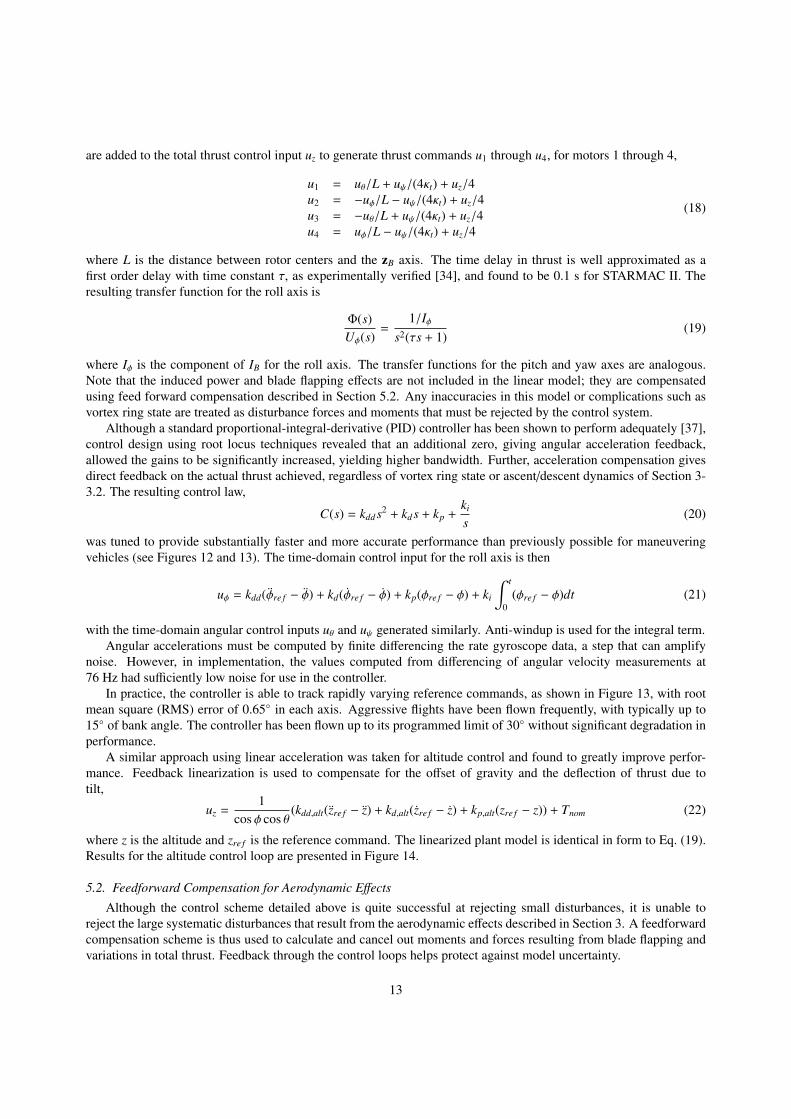
Figure 17: Autonomous indoor hover performance. (a) Position plot over 3 minutes of flight with 0.1 m error circle. (b) Histogram of positionerror in North and East directions.
This trajectory controller has some interesting properties. Since the path is composed only of line segments,overshoot on sharp corners is inevitable, a systematic tracking error. This is addressed by the alternative option usingleast-norm feed forward inputs, as described above. Another property arises due to the lack of mandated times to be ateach waypoint. The trajectory tracking controller does not deviate from the intended path to try to meet a deadline–arequired feature when the path is meant to avoid obstacles.
5.4. Applications
The precise, accurate control enabled by the controllers described above have allowed STARMAC to become auseful and flexible research platform. Although the details of these applications are outside the scope of this paper, abrief discussion of several flight experiments will be presented to highlight the utility of the STARMAC quadrotors indeveloping and demonstrating multi-vehicle control algorithms.
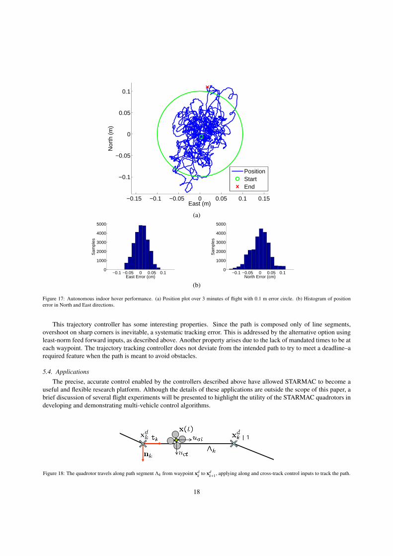
Figure 18: The quadrotor travels along path segment Λk from waypoint xdk to xd
k+1, applying along and cross-track control inputs to track the path.
18

−0.6 −0.4 −0.2 0 0.2 0.4 0.6
−0.6
−0.4
−0.2
0
0.2
0.4
East (m)
Nor
th (
m)
−4 −2 0 2 40
2
4
6
8
10
East (m)N
orth
(m
)
(a) (b)
Figure 19: Tracking a trajectory (a) indoors, at 0.5 m/s, with an error of under 0.1 m, and (b) outdoors, at 2.0 m/s, with an error of under 0.5 m.
Decentralized multi-vehicle collision avoidance is a very important issue for multi-vehicle systems. STARMACwas used to demonstrate a decentralized algorithm designed to generate optimal, collision-free trajectories usingNash Bargaining [12]. For the flight test, three STARMAC quadrotors were placed such that their desired trajectorieswould result in violating a minimum separation distance. The quadrotors communicated with each other to generatesafe trajectories using only their onboard computation, and successfully flew these trajectories (see Figure 20a).
Another important task for UAVs is performing obstacle avoidance in tight areas. For this particular experiment,a minimum-time, optimal trajectory was generated from an obstacle map using the Tunnel-MILP algorithm [15, 16].This trajectory was generated off-board and transmitted to a STARMAC quadrotor, which then successfully bypassedthe obstacles placed in the field. Figure 20b shows both the obstacle field and the desired and actual trajectories of theSTARMAC quadrotor.
Finally, another experiment was conducted using a pair of STARMAC quadrotors to cooperatively locate a mag-netic avalanche rescue beacon [43]. The STARMAC quadrotors used onboard avalanche rescue sensors to updateparticle filter representations of the location of an unknown beacon (blue dots in Figure 20c) and used an information-theoretic approach to generate trajectories that maximized information gain [13, 14]. All optimization and controlwas performed using the on-board PC104 computers.
6. Conclusion
This work describes in detail the vehicle dynamics, vehicle design, and control system design of the STARMACquadrotor testbed. With the successful completion of autonomous trajectory tracking flight demonstrations on thequadrotor helicopters of the STARMAC platform, a major milestone has been achieved not only for the testbed butalso for the development of quadrotors as viable autonomous micro-aerial vehicles. The many lessons learned inthe process of developing these vehicles should be of significant utility to any other groups interested in accessible,trouble-free UAV development.
Many exciting avenues of future investigations are now possible. For example, the incorporation of the aerody-namic effects outlined in Section 3 into the trajectory tracking control law will allow for more precise tracking andtherefore enable high speed operation in cluttered environments. Similarly, the expansion of multi-vehicle capabili-ties is now a priority, as is the incorporation of additional sensors to enable on-board estimation of and operation in
19

(a) (b) (c)
Figure 20: Experimental flight tests conducted using the STARMAC platform and controllers discussed in this paper showing (a) decentralizedcooperative collision avoidance using Nash bargaining; flight experiment and iterative solutions, (b) obstacle avoidance using the Tunnel-MILPalgorithm; flight experiment and computed path through the tunnel decomposition, and (c) information-theoretic cooperative search; quadrotorscarrying beacon receivers and mutual information contours for one vehicle
20

unknown environments. With STARMAC, a reliable, capable and convenient testbed of autonomous aerial vehicles,the multi-vehicle applications for which it was developed are now clearly within reach.
Acknowledgments
The authors would like to thank Jung Soon Jang, David Shoemaker, David Dostal, Dev Gorur Rajnarayan, VijayPradeep, Paul Yu, Justin Hendrickson, and Michael Vitus, for their many contributions to the development of theSTARMAC testbed. We would also like to thank Mark Woodward for the image processing program used for theUSB camera system.
References
[1] G. M. Hoffmann, S. L. Waslander, C. J. Tomlin, Distributed cooperative search using information-theoretic costs for particle filters withquadrotor applications, in: Proc. AIAA Guidance, Navigation, and Control Conf., Keystone, CO.
[2] Liz Hull, Drone makes first UK ’arrest’ as police catch car thief hiding under bushes, Daily Mail Online, 2010. http://www.dailymail.co.uk/news/article-1250177/Police-make-arrest-using-unmanned-drone.html.
[3] Microdrones GmbH, MD4-200 quadrotor helicopter, 2008. http://www.microdrones.com/news\_waypoint\_navigation.html.[4] Ascending Technologies GmbH, AscTec hummingbird, 2008. http://www.asctec.de.[5] DraganFly-Innovations, DraganFlyer X4 (2009). http://www.rctoys.com.[6] Aeryon Labs Inc., Aeryon Scout (2009). www.aeryon.com.[7] M. Valenti, B. Bethke, G. Fiore, J. P. How, E. Feron, Indoor multi-vehicle flight testbed for fault detection, isolation, and recovery, in: Proc.
AIAA Guidance, Navigation, and Control Conf., Keystone, CO.[8] M. Achtelik, A. Bachrach, R. He, S. Prentice, N. Roy, Autonomous navigation and exploration of a quadrotor helicopter in GPS-denied
indoor environments, in: AUVSI First Symposium on Indoor Flight Issues, Mayaguez, Puerto Rico.[9] N. Michael, J. Fink, V. Kumar, Cooperative manipulation and transportation with aerial robots, Robotics: Science and Systems,(Seattle, WA)
(2009).[10] S. Lupashin, A. Schollig, M. Sherback, R. DAndrea, A simple learning strategy for high-speed quadrocopter multi-flips (2010).[11] S. L. Waslander, G. Inalhan, C. J. Tomlin, Decentralized optimization via nash bargaining, in: D. Grundel, R. Murphey, P. M. Pardalos (Eds.),
Theory and Algorithms for Cooperative Systems, volume 4, World Scientific Publishing Co., 2004, pp. 565–585.[12] S. L. Waslander, C. J. Tomlin, Decentralized optimization and the nash bargaining solution for autonomous collision avoidance, submitted
to IEEE Transactions on Control Systems Technology (2010).[13] G. M. Hoffmann, S. L. Waslander, C. J. Tomlin, Mutual information methods with particle filters for mobile sensor network control, in: Proc.
45th IEEE Conf. Decision and Control, San Diego, CA, pp. 1019–1024.[14] G. M. Hoffmann, C. J. Tomlin, Mobile sensor network control using mutual information methods and particle filters, IEEE Transactions on
Automatic Control 55 (2010) 32–47.[15] M. Vitus, V. Pradeep, G. M. Hoffmann, S. L. Waslander, C. J. Tomlin, Tunnel-MILP: Path planning with sequential convex polytopes, in:
2008 AIAA Guidance, Navigation and Control Conference and Exhibit, Honolulu, Hawaii, USA.[16] M. P. Vitus, S. L. Waslander, C. J. Tomlin, submitted to the IEEE Journal of Robotics (2010).[17] J. Gillula, H. Huang, M. P. Vitus, C. J. Tomlin, Design of guaranteed safe maneuvers using reachable sets: Autonomous quadrotor aerobatics
in theory and practice, in: In the Proceedings of the 2010 IEEE International Conference on Robotics and Automation, Anchorage, Alaska.[18] S. Newman, The Foundations of Helicopter Flight, Halsted Press, New York, NY, pp. 107–116.[19] J. G. Leishman, Principles of Helicopter Aerodynamics, Cambridge University Press, New York, NY, pp. 36–71.[20] R. W. Prouty, Helicopter Performance, Stability, and Control, Krieger Publishing Company, Malabar, FL, pp. 143–146, 476–477.[21] E. Altug, J. P. Ostrowski, C. J. Taylor, Quadrotor control using dual camera visual feedback, in: Proc. IEEE Int. Conf. on Robotics and
Automation, Taipei, Taiwan, pp. 4294–4299.[22] DraganFly-Innovations, DraganFlyer V (2008). http://www.rctoys.com.[23] S. Bouabdallah, P. Murrieri, R. Siegwart, Towards autonomous indoor micro vtol, Autonomous Robots 18 (2005) 171–183.[24] P. Pounds, R. Mahony, J. Gresham, P. Corke, J. Roberts, Towards dynamically-favourable quad-rotor aerial robots, in: Proc. of the Aus-
tralasian Conf. on Robotics and Automation, Canberra, Australia.[25] P. Pounds, R. Mahony, P. Corke, Modelling and control of a quad-rotor robot, in: Proc. of the Australasian Conf. on Robotics and Automation,
Auckland, New Zealand.[26] P. Pounds, R. Mahony, P. Corke, Modelling and control of a large quadrotor robot, Control Engineering Practice 18 (2010) 691–699.[27] G. Hoffmann, D. G. Rajnarayan, S. L. Waslander, D. Dostal, J. S. Jang, C. J. Tomlin, The stanford testbed of autonomous rotorcraft for multi
agent control (starmac), in: Proc. 23rd Digital Avionics Systems Conf., Salt Lake City, UT, pp. 12.E.4/1–10.[28] N. Guenard, T. Hamel, V. Moreau, Dynamic modeling and intuitive control strategy for an x4-flyer, in: Proc. IEEE Int. Conf. on Robotics
and Automation, Budapest, Hungary, pp. 141–146.[29] J. Escareno, S. Salazar-Cruz, R. Lozano, Embedded control of a four-rotor uav, in: Proc. AACC Amer. Control Conf., Minneapolis, MN, pp.
3936–3941.[30] E. B. Nice, Design of a Four Rotor Hovering Vehicle, Master’s thesis, Cornell University, 2004.[31] S. Park, et al., Ric (robust internal-loop compensator) based flight control of a quad-rotor type uav, in: IEEE/RSJ Int. Conf. on Intelligent
Robotics and Syst., Edmonton, Alberta.
21

[32] S. Craciunas, C. Kirsch, H. Rock, R. Trummer, The javiator: A high-payload quadrotor uav with high-level programming capabilities, Proc.GNC. AIAA (2008).
[33] J. Courbon, Y. Mezouar, N. Guenard, P. Martinet, Vision-based navigation of unmanned aerial vehicles, Control Engineering Practice 18(2010) 789–799.
[34] G. M. Hoffmann, H. Huang, S. L. Waslander, C. J. Tomlin, Quadrotor helicopter flight dynamics and control: Theory and experiment, in:Proc. AIAA Guidance, Navigation, and Control Conf., Hilton Head, SC.
[35] H. Huang, G. M. Hoffmann, S. L. Waslander, C. Tomlin, Aerodynamics and control of autonomous quadrotor helicopters in aggressivemaneuvering, in: Proc. IEEE Int. Conf. on Robotics and Automation, Kobe, Japan, pp. 3277–3282.
[36] W. Johnson, Helicopter Theory, Princeton University Press, Princeton, NJ, pp. 126–131.[37] S. L. Waslander, G. M. Hoffmann, J. S. Jang, C. J. Tomlin, Multi-agent quadrotor testbed control design: Integral sliding mode vs. reinforce-
ment learning, in: IEEE/RSJ Int. Conf. on Intelligent Robotics and Syst., Edmonton, Alberta, pp. 468–473.[38] G. E. Computers, Robostix and Verdex Boards, 2008. http://www.gumstix.com/.[39] Advanced Digital Logic, ADL855 PC104+, 2008. http://www.adlogic-pc104.com/products/cpu/pc104/datasheets/MSM855.
pdf.[40] Videre Design, STH-MDCS 2 Stereo Vision Head, 2008. http://www.videredesign.com/sthmdcs2.htm.[41] Hokuyo, URG-04LX Laser Range Finder, 2008. http://www.hokuyo-aut.jp/products/urg/urg.htm.[42] BackCountry Access, Tracker DTS Digital Avalanche Beacon, 2008. http://www.bcaccess.com/bca\_products/tracker/index.
php.[43] G. M. Hoffmann, Autonomy for Sensor-Rich Vehicles: Interaction between Sensing and Control Actions, Ph.D. thesis, Stanford University,
2008.
22