new vma14 implementing live mobility with virtual fibre ... · pdf filesession title:...
TRANSCRIPT

© 2009 IBM Corporation
Session Title: Implementing Live Mobility with Virtual Fibre Channel
Speaker Name: Ron Barker
Session ID: VMA14
2009 IBM POWER Systems Technical University
September 21 – 25, 2009 – Orlando, FL

2
IBM Training
© 2009 IBM Corporation
Agenda
�Virtual I/O Server overview
�N_Port ID Virtualization (NPIV) overview
�Implementing NPIV – prerequisites
�Steps to NPIV implementation
�NPIV and Live Partition Mobility
3
IBM Training
© 2009 IBM Corporation
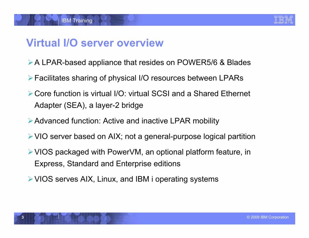
Virtual I/O server overview
�A LPAR-based appliance that resides on POWER5/6 & Blades
�Facilitates sharing of physical I/O resources between LPARs
�Core function is virtual I/O: virtual SCSI and a Shared Ethernet
Adapter (SEA), a layer-2 bridge
�Advanced function: Active and inactive LPAR mobility
�VIO server based on AIX; not a general-purpose logical partition
�VIOS packaged with PowerVM, an optional platform feature, in
Express, Standard and Enterprise editions
�VIOS serves AIX, Linux, and IBM i operating systems

4
IBM Training
© 2009 IBM Corporation
NPIV overview
�N_Port ID Virtualization (NPIV) is a fibre channel industry
standard for virtualizing a physical fibre channel port.
�NPIV allows one physical port to be associated with multiple
virtual ports, so a single physical adapter can be shared
across multiple guest operating systems
�On Power Systems, NPIV allows logical partitions (LPARs) to
have a unique identity to the SAN, just as if it had a dedicated
physical fibre channel adapter

5
IBM Training
© 2009 IBM Corporation
vSCSI NPIV
EMC
In the vSCSI model, the VIOS is a storage virtualizer. Heterogeneous storage is pooled by the VIOS into a homogeneous pool of block storage and then allocated to client LPARs in the form of generic SCSI LUNs. The VIOS performs SCSI emulation and acts as the SCSI Target.
With NPIV, the VIOS's role is fundamentally different. The VIOS facilitates adapter sharing only. There is no device level abstraction or emulation. Rather than a storage virtualizer, the VIOS serving NPIV is a pass-thru device, providing an FCP connection from the client to the SAN.
vio client
VIOS
FC HBAs
EMC
generic scsi disk
generic scsi disk
IBM 2105
VIOS
FC HBAs
SAN
vio client
FCPVIOS
FC HBAs
EMC IBM 2105
VIOS
FC HBAs
SAN
IBM 2105EMC
SCSI

6
IBM Training
© 2009 IBM Corporation
NPIV specifics
� VIOS V2.1 (PowerVM Express, Standard, and Enterprise)
�Client OS support: AIX(5.3, 6.1); Suse SLES 11, Red Hat 5.4; IBM i later
this year
� POWER6 only; Blade support next month
� 8 Gigabit PCI Express Dual Port Fibre Channel Adapter
�Compatible with Live Partition Mobility (LPM)
� VIO servers can support NPIV and vSCSI simultaneously
�Clients can support NPIV, vSCSI and dedicated Fibre Channel
simultaneously
�HMC-managed or IVM-managed servers
�Unique Worldwide Port Name (WWPN) generation (allocated in pairs) for
each virtual adapter

7
IBM Training
© 2009 IBM Corporation
NPIV benefits
�Ability to use multi-path code commands specific to the storage without having to go to the VIO server
�Avoids VIOS physical-to-virtual disk compatibility issues, thus enabling bit-by-bit utilities such as FlashCopy, TruCopy, MetroMirror, SRDF, etc.
�Avoids having to map LUNs from the VIOSs to the VIOCs
�Avoids having to manage SCSI reserves with dual VIOSs
�Allows an administrator to manage queue_depth at the VIOC rather than at both the VIOS and VIOC
�Ability to attach tape libraries

8
IBM Training
© 2009 IBM Corporation
NPIV limitations
�Installing storage management code on the client instead of the VIO server means you potentially will have many different copies of code to install and maintain
�Updating multi-path code may require a reboot of the partition, causing an outage
• Updating multi-path code when booting from SAN can be complicated
• With dual VIO servers and VSCSI, an interruption to the client’s operation could be avoided since one VIOS could be available during the update process

9
IBM Training
© 2009 IBM Corporation
Live Partition Mobility and NPIV
VIOS
N P I V
vio client WWPN
VIOS
N P I V
vio client
vio client
vio client
WWPN
WWPN
WWPN
WWPN
WWPN
VIOS
N P I V
vio client WWPN
VIOS
N P I V
vio client
vio client
vio client
WWPN
WWPN
WWPN
WWPN
WWPN NPIV enabledSAN
•WWPNs are allocated in pairs

10
IBM Training
© 2009 IBM Corporation
Implementing NPIV - prerequisites
�OS Levels
• AIX 5.3 with 5300-09 Technology Level or greater
• AIX 6.1 with 6100-02 Technology Level or greater
• IBM I 6.1.1 (4Q09)
• SUSE Linux Enterprise Server 11 for POWER Systems
• Red Hat Enterprise Linux for POWER version 5.4
11
IBM Training
© 2009 IBM Corporation
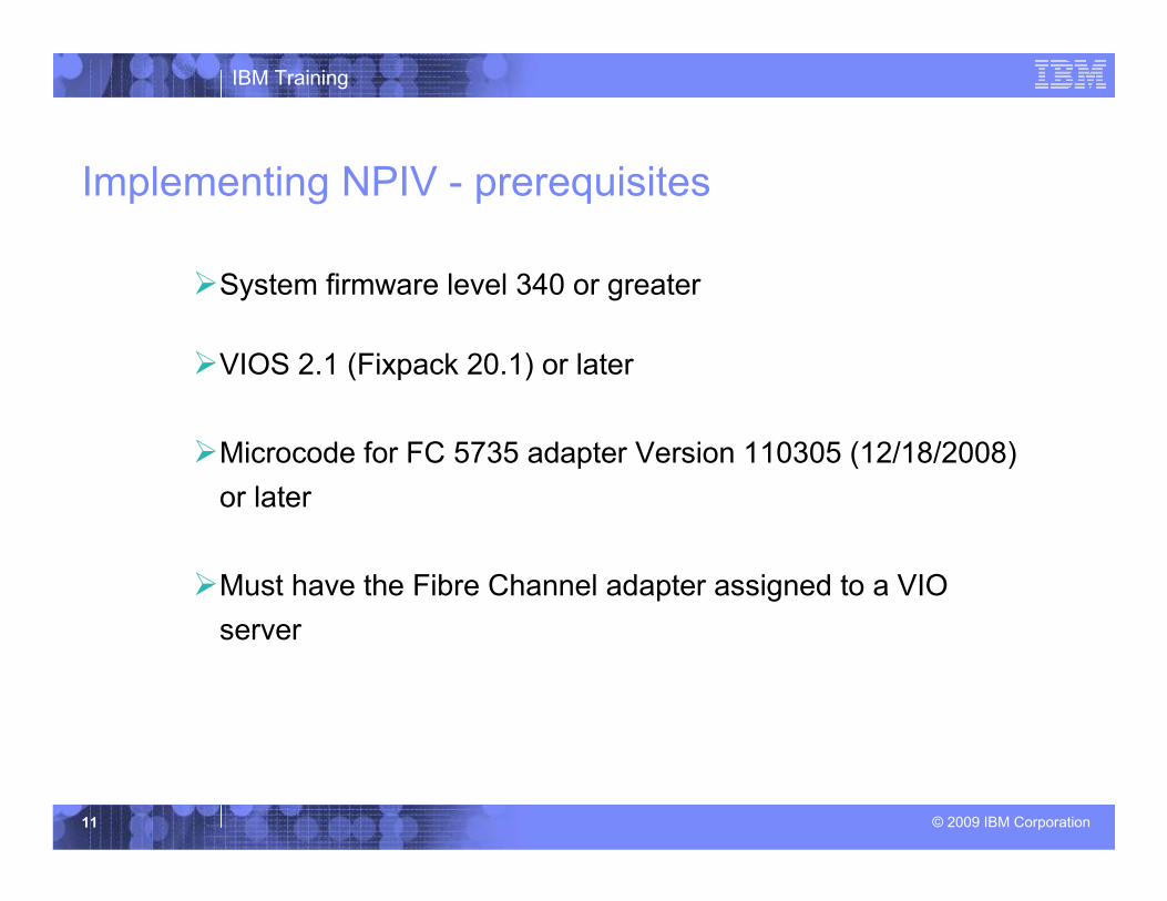
Implementing NPIV - prerequisites
�System firmware level 340 or greater
�VIOS 2.1 (Fixpack 20.1) or later
�Microcode for FC 5735 adapter Version 110305 (12/18/2008)
or later
�Must have the Fibre Channel adapter assigned to a VIO
server

12
IBM Training
© 2009 IBM Corporation
Make sure SAN switch is NPIV capable
�Only the first SAN switch attached to the Fibre Channel
adapter needs to be NPIV capable
• Other switches in the environment do not need to be NPIV
capable
• Not all ports on the switch need to be configured for NPIV, just
the one which the adapter will use
�Check with your storage vendor to make sure the switch is
NPIV capable
�Order and install the latest available firmware for your SAN
switch to enable this feature

13
IBM Training
© 2009 IBM Corporation
Create a virtual Fibre Channel server adapter
Create either in initial VIOS configuration or add via DLAP; then save to permanent configuration

14
IBM Training
© 2009 IBM Corporation
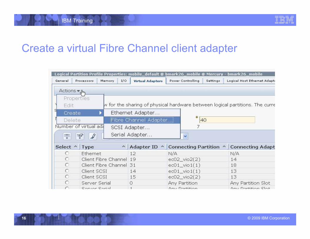
Create a virtual Fibre Channel client adapter
�Create the virtual adapter when the profile is built or use
DLPAR to add the virtual adapter later
�To edit an existing profile
• Select the client partition
• Go to Tasks – Configuration – Manage Profiles
• Select the profile, e.g., Default
• Under Actions, select Edit
• Select Virtual Adapters, then select Actions -> Create -> Fibre
Channel Adapter
(See next three slides for examples)

15
IBM Training
© 2009 IBM Corporation
Create a virtual Fibre Channel client adapter
16
IBM Training
© 2009 IBM Corporation
Create a virtual Fibre Channel client adapter

17
IBM Training
© 2009 IBM Corporation
Map the client virtual FC to the server virtual FC

18
IBM Training
© 2009 IBM Corporation
Login to VIO server
�If DLPAR was used, run cfgdev to make the virtual
FC server adapter available
�Verify the virtual FC server adapter• $ lsdev -dev vfchost*
• name status description
• vfchost0 Available Virtual FC Server Adapter
• $

19
IBM Training
© 2009 IBM Corporation
View available physical FC adapters
$ lsdev -dev fcs*
name status description
fcs0 Available FC Adapter
fcs1 Available FC Adapter
fcs2 Available 4Gb FC PCI Express Adapter
(df1000fe)
fcs3 Available 4Gb FC PCI Express Adapter
(df1000fe)
fcs4 Available 8Gb PCI Express Dual Port FC Adapter
(df1000f114108a03)
fcs5 Available 8Gb PCI Express Dual Port FC Adapter
(df1000f114108a03)
$

20
IBM Training
© 2009 IBM Corporation
VIOS view of the 8 Gbps Fibre Channel adapter
$ lsdev -dev fcs4 -vpd
fcs4 U789D.001.DQDVXNB-P1-C6-T1 8Gb PCI Express
Dual Port FC Adapter (df1000f114108a03)
Part Number.................10N9824
Serial Number...............1B839042F5
Manufacturer................001B
EC Level....................D76482A
Customer Card ID Number.....577D
FRU Number..................10N9824
Device Specific.(ZM)........3
Network Address.............10000000C9809732
…
fcs5 is T2 (port 2) for this adapter

21
IBM Training
© 2009 IBM Corporation
Run lsnports to verify readiness to connect
$ lsnportsname physloc fabric tports aports swwpns awwpns
fcs4 U789D.001.DQDVXNB-P1-C6-T1 1 64 63 2048 2045
Name Physical port name
Physloc Physical port location code
Fabric Fabric support
Tports Total number of virtual ports
Aports Number of available virtual ports – as yet unused
Swwpns Total number of client worldwide port names supported
Awwpns Number of client worldwide port names available

22
IBM Training
© 2009 IBM Corporation
Map the vfchost to the physical adapter port
�vfcmap – binding the VFC Server to the Fibre Channel Port
• vfcmap -help
Usage: vfcmap -vadapter VFCServerAdapter -fcp FCPName
Maps the Virtual Fibre Channel Adapter to the physical Fibre
Channel Port
-vadapter Specifies the virtual server adapter.
-fcp Specifies the physical Fibre Channel Port
Example:
$ vfcmap –vadapter vfchost0 –fcp fcs4
23
IBM Training
© 2009 IBM Corporation
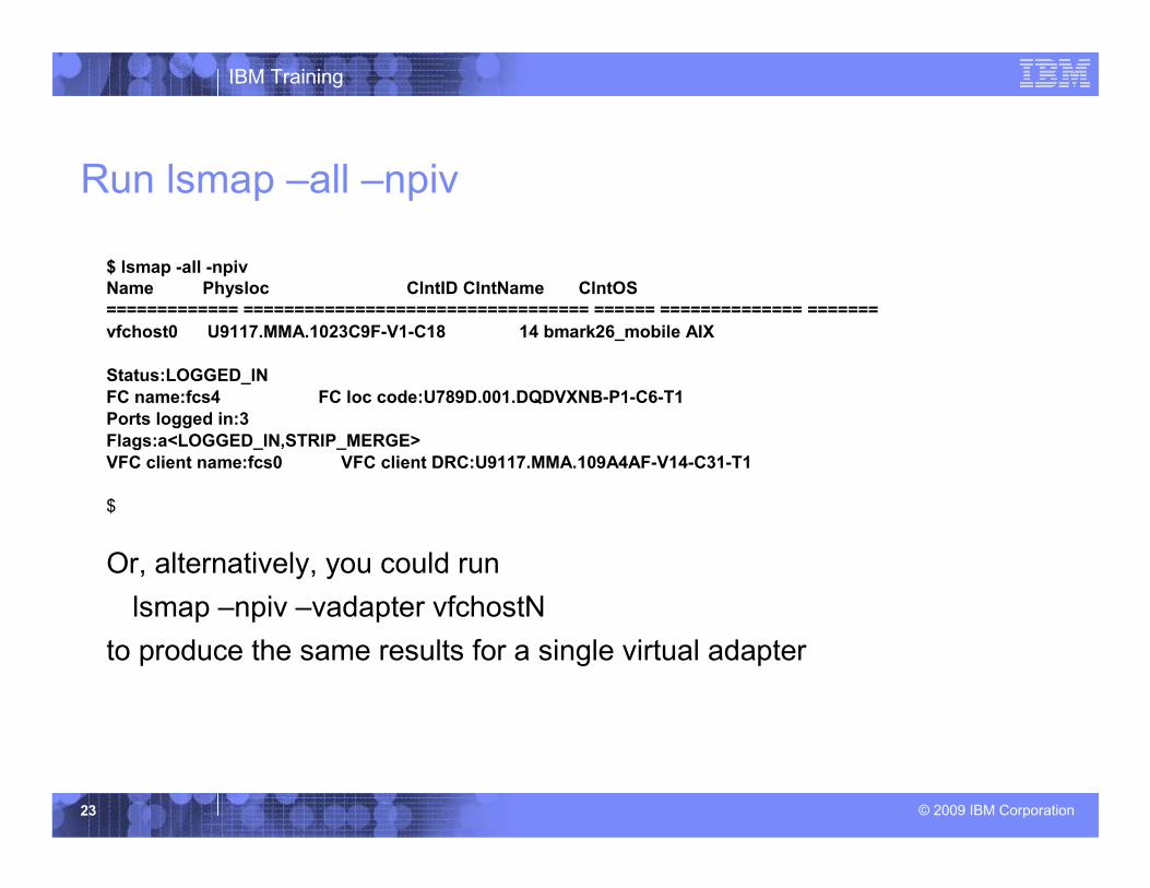
Run lsmap –all –npiv
$ lsmap -all -npivName Physloc ClntID ClntName ClntOS
============= ================================== ====== ============== =======
vfchost0 U9117.MMA.1023C9F-V1-C18 14 bmark26_mobile AIX
Status:LOGGED_IN
FC name:fcs4 FC loc code:U789D.001.DQDVXNB-P1-C6-T1
Ports logged in:3
Flags:a<LOGGED_IN,STRIP_MERGE>
VFC client name:fcs0 VFC client DRC:U9117.MMA.109A4AF-V14-C31-T1
$
Or, alternatively, you could run
lsmap –npiv –vadapter vfchostN
to produce the same results for a single virtual adapter

24
IBM Training
© 2009 IBM Corporation
Zoning in the switch and LUN masking
� Make sure switch is NPIV capable and is running the latest
firmware, and that the port you are using is NPIV enabled
�You need to use the client’s world wide port names (WWPN)
on the switch and the storage subsystem
� First, put the VFC in the correct switch zone
� Next, map the LUN to the WWPN
�Provide both the primary and secondary WWPN (assigned as
a pair) to enable Live Partition Mobility
�The WWPN of the physical Fibre Channel adapter (server) is
NOT needed

IBM Training
© 2009 IBM Corporation
Switch View

IBM Training
© 2009 IBM Corporation
Mappings

IBM Training
© 2009 IBM Corporation
Storage View

28
IBM Training
© 2009 IBM Corporation
How to find the partition’s world wide port names

29
IBM Training
© 2009 IBM Corporation
Edit the default profile of the client

30
IBM Training
© 2009 IBM Corporation
Select the client Fibre Channel adapter

31
IBM Training
© 2009 IBM Corporation
Properties of the client virtual FC adapter
Primary WWPN
Secondary WWPN
Keep False for LPM

32
IBM Training
© 2009 IBM Corporation
Why two worldwide port names?
� For Live Partition Mobility, both primary and secondary worldwide port
names (WWPN) for the client partition need to be entered in the switch
�The primary WWPN shows up automatically when the LPAR
connects, but the secondary must be added manually
� The secondary WWPN is used during mobility to login to the target VIO
server’s FC adapter to verify connectivity to the LUN
� During the migration, both primary and secondary WWPNs will be visible on
the switch
� After the migration, the secondary WWPN will be one seen
� The primary WWPN will be used to login to the destination server during the
next migration; round-robin usage

33
IBM Training
© 2009 IBM Corporation
Install appropriate disk management software
�Because the client is the entity managing the disk, the software will
be installed there instead of on the VIO server, as in the past
�For most IBM storage -- ESS, DS6000, DS8000, SVC, DS5000 and
most DS4000s -- the Subsystem Device Driver Path Control Module
(SDDPCM) is recommended
• Check to make sure you use the appropriate software for your storage
subsystem

IBM Training
© 2009 IBM Corporation
Initiating Live Partition Mobility
� A migration can be started from the HMC graphical user interface or via command line
� Mobile partitions must reside on the same network subnet and the SAN storage must be accessible from all servers
� Target servers must be able to provide at least the minimum desired CPU and memory resources

IBM Training
© 2009 IBM Corporation
Initiating Live Mobility
� The Hypervisor will automatically manage migration of CPU and memory
�Dedicated I/O adapters, if any, must be de-allocated before migration
• Available dedicated I/O adapters may be dynamically added after the migration
�The operating system and applications must be migration-aware or migration-enabled

IBM Training
© 2009 IBM Corporation
Initiating Live Mobility
� When using virtual Fibre Channel, LUNs do not need to have SCSI reserve turned off
• This is contrary to what is required when using Virtual SCSI devices
• In VSCSI, two or more VIO servers may be accessing the target disks and virtualizing them to the clients
• In VFC, only the client is accessing the target disks before, during and after the migration

IBM Training
© 2009 IBM Corporation
Validation
�Capability and compatibility check
�Resource Monitoring and Control (RMC) check
�Partition readiness
�System resource availability
�Virtual adapter mapping (i.e., availability of a VFC server adapter)
�Operating system and application readiness check

IBM Training
© 2009 IBM Corporation
Migration
�If validation passes, migration can begin�From this point, all state changes are rolled back if an error occurs
POWER Hypervisor
Source System Target System
POWER Hypervisor
Mobile Partition
Mobile Partition
MSP MSP
VASI VASI
Partition State Transfer Flow
1 2
3
4 52
3
4 5

IBM Training
© 2009 IBM Corporation
Migration Steps (1 of 6)
�The HMC creates a shell partition on the destination system
�The HMC configures the source and destination Mover Service Partitions (MSP)
• MSPs connect to PHYP thru the Virtual Asynchronous Serial Interface (VASI)
�The MSPs set up a private, full-duplex channel to transfer partition state data

IBM Training
© 2009 IBM Corporation
Migration Steps (2 of 6)
�The HMC sends a Resource Monitoring and Control (RMC) event to the mobile partition so it can prepare for migration
�The HMC creates the virtual target devices and virtual SCSI adapters in the destination MSP
�The MSP on the source system starts sending the partition state to the MSP on the destination server

IBM Training
© 2009 IBM Corporation
Migration Steps (3 of 6)
�The source MSP keeps copying memory pages to the target in successive phases until modified pages have been reduced to near zero
�The MSP on the source instructs the PHYP to suspend the mobile partition
�The mobile partition confirms the suspension by suspending threads
IBM Training
© 2009 IBM Corporation
Migration Steps (4 of 6)
�The source MSP copies the latest modified memory pages and state data
�Execution is resumed on the destination server and the partition re-establishes the operating environment
�The mobile partition recovers I/O on the destination server and retries all uncompleted I/O operations that were going on during the suspension
• It also sends gratuitous ARP requests to all VLAN adapters

IBM Training
© 2009 IBM Corporation
Migration Steps (5 of 6)
�When the destination server receives the last modified pages, the migration is complete
�In the final steps, all resources are returned to the source anddestination systems and the mobile partition is restored to its fully functional state
�The channel between MSPs is closed
�The VASI channel between MSP and PHYP is closed
�Virtual adapters on the source MSP are removed

IBM Training
© 2009 IBM Corporation
Migration Steps (6 of 6)
�The HMC informs the MSPs that the migration is complete and all migration data can be removed from their memory tables
�The mobile partition and all its profiles are deleted from the source server
�You can now add dedicated adapters to the mobile partition via DLPAR as needed, or put it in an LPAR workload group

45
IBM Training
© 2009 IBM Corporation
References
�IBM Redbooks
• PowerVM Virtualization on IBM Power Systems (Volume
2): Managing and Monitoring (SG24-7590-01)
• IBM PowerVM Live Partition Mobility (SG24-7460-01)