nf 100 kt .18 s - wolflabs flodos ba_liquiport_en_02_153820.docx translation of original operating...
TRANSCRIPT

KNF Flodos BA_LIQUIPORT_EN_02_153820.docx
Translation of Original Operating Instructions Keep for future reference!
Diaphragm Laboratory Pump
LIQUIPORT®
Operating instructions Read and observe these operat-ing and installation instructions! An additional letter prefixing the FEM model code is a country-specific designation, and does not have any technical significance.
KNF FLODOS AG Wassermatte 2 6210 Sursee, Switzerland
Tel. +41 (0)41 925 00 25 Fax +41 (0)41 925 00 35
www.knf-flodos.ch [email protected]
NF 100 KT .18 S
.18
100 / 1.100 / 300 / 1.300
NF
S / RC
- / PMLxxxx / PLxxxx
KT / TT / FT
Items included on delivery:
Liquiport® Laboratory pump
Mains plug
RC cable (for RC version only)
Operating manual
Safety provisions
The Liquiport® laboratory pump complies with the
safety provisions of the EC low-voltage directive
2006/95/EC and the EC directive on electromag-
netic compatibility 2004/108/EC. The following
harmonised standards are applicable:
EN 61010-1
EN 61326-1
Contents Page Contents Page
1. About this document 3
1.1. Use of the operating and installation instructions 3
1.2. Symbols and markings 3
2. Use 4
2.1. Intended use 4
2.2. Improper use 4
3. Safety 5
4. Technical data 7
4.1. Pump materials 7
4.2. Hydraulic ratings 8
4.3. Hydraulic connections 9
4.4. Electrical Data 10
4.5. Other parameters 10
4.6. External actuation (RC version only) 11
5. Assembly and function 12
5.1. Design of the laboratory pump 12
5.2. Operating principle 12
6. Installation and connection 13
6.1. Installation 13
6.2. Electrical connection 15
6.3. External drive (RC version) 15
6.4. Hydraulic connection 16
6.5. Shutdown 17
6.6. Transport and interim storage 17
7. Operation 18
7.1. Initial start-up 18
7.2. Operating controls 19
7.3. Starting the pump 19
7.4. Stopping the pumping operation 19
7.5. Adjusting the flow rate 20
8. RC version – external actuation 21
8.1. External actuation analogue input 21
8.2. Start/stop pulse input 22
8.3. Foot switch 23
8.4. Digital output 23
9. Servicing 24
9.1. Servicing schedule 24
9.2. Cleaning 24
9.3. Cleaning/replacing valve plates and pump diaphragm 25
10. Troubleshooting 28
11. Spare parts and accessories 30
11.1. Spare parts 30
11.2. Accessories 30
12. Decontamination declaration 31

LIQUIPORT Diaphragm Laboratory Pump About this document
KNF Flodos BA_LIQUIPORT_EN_02_153820.docx
Translation of Original Operating Instructions 3
1. About this document
1.1. Use of the operating and installation instruc-tions
The operating and installation instructions are part of the pump.
Pass on the operating and installation instructions to the next
owner.
Customer-specific project pumps (pump models which begin with
"PL" or "PML") may differ from the operating and installation in-
structions.
In the case of project pumps, take note of any additionally
agreed specifications.
1.2. Symbols and markings
Warning
WARNING
This symbol indicates a potential danger. It also indicates the possible consequences of failure
to observe the warning. The signal word (i.e. "Warn-
ing") indicates the level of danger. This specifies measures for avoiding the danger
and the consequences of failure to implement
these measures.
Danger levels
Signal word Meaning Consequences if not observed
DANGER warns of immedi-ate danger
Death or serious injuries and/or serious damage to property are the consequence.
WARNING warns of possible danger
Death or serious injuries and/or serious damage to property are possible.
CAUTION warns of a poten-tially dangerous situation
Minor injuries or damage to property are possible.
Tab. 1: Danger levels
Other information and symbols
This indicates an activity (step) that needs to be carried out.
This indicates the first step of an activity to be carried out. It will 1.
be followed by other consecutively numbered steps.
This symbol indicates important information.
Project pumps
Use LIQUIPORT Diaphragm Laboratory Pump
KNF Flodos BA_LIQUIPORT_EN_02_153820.docx
4 Translation of Original Operating Instructions
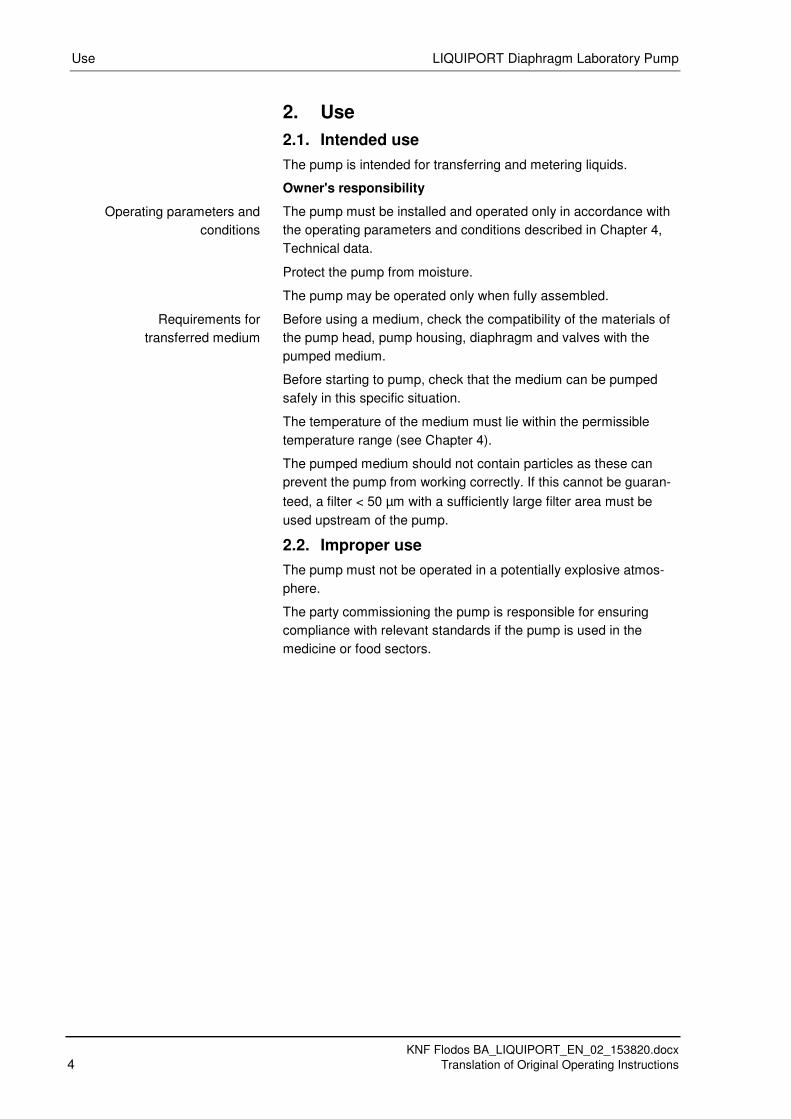
2. Use
2.1. Intended use
The pump is intended for transferring and metering liquids.
Owner's responsibility
The pump must be installed and operated only in accordance with
the operating parameters and conditions described in Chapter 4,
Technical data.
Protect the pump from moisture.
The pump may be operated only when fully assembled.
Before using a medium, check the compatibility of the materials of
the pump head, pump housing, diaphragm and valves with the
pumped medium.
Before starting to pump, check that the medium can be pumped
safely in this specific situation.
The temperature of the medium must lie within the permissible
temperature range (see Chapter 4).
The pumped medium should not contain particles as these can
prevent the pump from working correctly. If this cannot be guaran-
teed, a filter < 50 µm with a sufficiently large filter area must be
used upstream of the pump.
2.2. Improper use
The pump must not be operated in a potentially explosive atmos-
phere.
The party commissioning the pump is responsible for ensuring
compliance with relevant standards if the pump is used in the
medicine or food sectors.
Operating parameters and
conditions
Requirements for
transferred medium

LIQUIPORT Diaphragm Laboratory Pump Safety
KNF Flodos BA_LIQUIPORT_EN_02_153820.docx
Translation of Original Operating Instructions 5
3. Safety
Note the safety precautions in Chapters
6. Installation and connection, and 7. Operation.
The pump is built according to the generally recognised rules of
technology and in accordance with the pertinent occupational
safety and accident prevention regulations. Nevertheless, dangers
can result during its use, which lead to injuries to the user or oth-
ers, or to damage to the pump or other property.
Only use the pump in perfect working order and in accordance with
its intended use. Always ensure adherence to the operating and
installation instructions and work in a safety-conscious manner.
Make sure that only trained and instructed personnel or specially
trained personnel work on the pumps. This especially applies to
assembly, connection and servicing work.
Make sure that all personnel have read and understood the operat-
ing and installation instructions, and in particular the "Safety"
chapter.
Observe the accident prevention and safety regulations when
performing any work on the pump and during operation.
When pumping dangerous media, observe the safety regulations
for handling such media.
Always ensure adherence to all information stickers on the pumps,
such as flow direction arrows and type plates, and keep stickers in
legible condition.
All replacement parts should be properly stored and disposed of in
accordance with the applicable environmental protection regula-
tions. Ensure adherence to the pertinent national and international
regulations. This especially applies to parts contaminated with toxic
substances.
Dispose of all packaging in an environmentally appropriate
manner. The packaging materials are recyclable.
Ensure that the pump is disposed of in an environmentally
appropriate manner at the end of its useful life. Use appro-
priate waste collection systems for the disposal of end-of-
life equipment. Used pumps contain valuable recyclable
materials.
Personnel
Working in a
safety-conscious manner
Handling dangerous media
Notes
Environmental protection
Disposal

Safety LIQUIPORT Diaphragm Laboratory Pump
KNF Flodos BA_LIQUIPORT_EN_02_153820.docx
6 Translation of Original Operating Instructions
The pumps are in accordance with the requirements of the
guidelines 2011/65/EU (ROHS2)
The pump complies with all relevant provisions of the follow-
ing directives: the EC machinery directive 2006/42/EC,
safety provisions of the EC low-voltage directive 2006/95/EC
and the EC directive on electromagnetic compatibility
2004/108/EC.
The following harmonised standards are complied with:
EN 61010-1
EN 61326-1
All repairs to the pump(s) must be carried out by the relevant
KNF Customer Service team.
Only use KNF original parts for all maintenance work.
EU directives/standards
Customer services and
repairs

LIQUIPORT Diaphragm Laboratory Pump Technical data
KNF Flodos BA_LIQUIPORT_EN_02_153820.docx
Translation of Original Operating Instructions 7
4. Technical data
4.1. Pump materials
The type designation KT stands for:
Assembly Material1)
Pump head PP
Valve plate / seals FFPM
Diaphragm PTFE-coated
Housing PA, TPE, PC Tab. 2: KT
1) according to DIN ISO 1629 and 1043.1
The type designation TT stands for:
Assembly Material1)
Pump head PVDF
Valve plate / seals FFPM
Diaphragm PTFE-coated
Housing PA, TPE, PC Tab. 3: TT
1) according to DIN ISO 1629 and 1043.1
The type designation FT stands for:
Assembly Material1)
Pump head PTFE
Valve plate / seals FFPM
Diaphragm PTFE-coated
Housing PA, TPE, PC Tab. 4: FT
1) according to DIN ISO 1629 and 1043.1

Technical data LIQUIPORT Diaphragm Laboratory Pump
KNF Flodos BA_LIQUIPORT_EN_02_153820.docx
8 Translation of Original Operating Instructions
4.2. Hydraulic ratings
Type Liquiport® 100 Liquiport
® 1.100
Flow rate [l/min] 1) 2)
0.2 – 1.3 0.2 - 1.3
Suction head [mWG] 3 3
Permissible pressure [bar g] 1.0 6.0
Permissible viscosity of medium [cSt]
150 150
Tab. 5: Hydraulic ratings for Liquiport
® 100 / Liquiport
® 1.100
Fig. 1: Flow rate curve for Liquiport
® 100
Fig. 2: Flow rate curve for Liquiport
® 1.100
1) Measured with water at 20°C
2) Flow rates may vary from the values shown, depending on fluid
viscosity, pump head material and the hoses / hose connectors
used.

LIQUIPORT Diaphragm Laboratory Pump Technical data
KNF Flodos BA_LIQUIPORT_EN_02_153820.docx
Translation of Original Operating Instructions 9
Pump model Liquiport® 300 Liquiport
® 1.300
Flow rate [l/min] 1) 2)
0.5 – 3.0 0.5 - 3.0
Suction head [mWG] 3 3
Permissible pressure [bar g] 1.0 6.0
Permissible viscosity of medium [cSt]
150 150
Tab. 6: Hydraulic ratings
Fig. 3: Flow rate curve for Liquiport
® 300
Fig. 4: Flow rate curve for Liquiport
® 1.300
4.3. Hydraulic connections
Pump model Connection type
Liquiport® 100
Liquiport® 1.100
Internal thread NPT 1/8" with hose connector for hose ID 8mm
Liquiport® 300
Liquiport® 1.300
Internal thread NPT 1/8" with hose connector for hose ID 12mm
Tab. 7: Hydraulic connections

Technical data LIQUIPORT Diaphragm Laboratory Pump
KNF Flodos BA_LIQUIPORT_EN_02_153820.docx
10 Translation of Original Operating Instructions
4.4. Electrical Data
Pump model Liquiport® 100 Liquiport
® 1.100
Nominal mains voltage [V] 100 – 240V AC +/- 10%,
Frequency [Hz] 50-60 Hz
Max. power consumption AC 100 V / 115 V / 240 V [W]
12 / 12 / 12 15 / 15 / 16
Max. power consumption DC [W]
12 15
Pump DC voltage [V] 24 V DC
Max. current consumption DC RMS 24 V [A]
0.5 0.63
Max. short-term peak current [A] 0.8 0.8
Power supply protection Electronic overload protection
Pump protection Electronic overload protection Tab. 8: Electrical Data
Pump model Liquiport® 300 Liquiport
® 1.300
Nominal mains voltage [V] 100 – 240V AC +/- 10%,
Frequency [Hz] 50-60 Hz
Max. power consumption AC 100 V / 115 V / 240 V [W]
22 / 22 / 24 30 / 30 / 32
Max. power consumption DC [W]
22 29
Pump DC voltage [V] 24 V DC
Max. current consumption DC RMS 24 V [A]
0.92 1.2
Max. short-term peak current [A] 1.3 1.3
Power supply protection Electronic overload protection
Pump protection Electronic overload protection Tab. 9: Electrical Data
4.5. Other parameters
Pump model Liquiport® 100
Liquiport® 1.100
Liquiport® 300
Liquiport® 1.300
Weight of pump [kg] 1)
1.0 1.5
Permissible ambient tempera-ture [°C]
+5 to +40°C
Permitted medium tempera-ture
+5 to +80°C
Rated speed [rpm] 3000 rpm
Noise level [dBA] < 40dBA
Pump protection type IP 65
Power supply protection type IP 40
Protection class III
Tab. 10: Other parameters
1)
The weight may differ slightly from the stated value, depending
on the version.

LIQUIPORT Diaphragm Laboratory Pump Technical data
KNF Flodos BA_LIQUIPORT_EN_02_153820.docx
Translation of Original Operating Instructions 11
4.6. External actuation (RC version only)
Parameter Value
Analogue input
Signal range 0-10V
Signal range optional 1)
0-20mA
Input resistance [Ω] 133 kΩ at 0-10V
510 Ω at 0-20mA
Electric strength [V] TTL 24 V DC
Digital input
Signal range Pull up at 24 V
Electric strength [V] TTL 24 V DC
Low level (ON) < 0.8 V = low
High level (OFF) > 2.0 V = high
Pull-up resistance 10 kΩ
Resistance to ground 43 kΩ
Digital output
Electric strength open collector [V] TTL
24 V DC
Load capability open collector [mA] TTL
10mA
Tab. 11: External actuation
1) Optional on request.
1 Analogue input Brown
2 External actuation jumper White
3 Pulse input Blue
4 Open collector output Black
5 Ground Grey
Fig. 5: RC cable pins
Pin No. Wire colour Description Function
1 Brown Analogue input (0%) 15% to 100% flow rate
2 White External actuation jumper
Switches pump over to external actuation. Control knob is deactivated
3 Blue Pulse input Start/Stop via external actuation
4 Black Open collector output
Operating mode output (On/Off)
5 Grey Ground -- Tab. 12: RC cable pins
Assembly and function LIQUIPORT Diaphragm Laboratory Pump
KNF Flodos BA_LIQUIPORT_EN_02_153820.docx
12 Translation of Original Operating Instructions
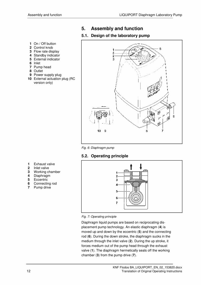
5. Assembly and function
5.1. Design of the laboratory pump
1 On / Off button 2 Control knob 3 Flow rate display 4 Standby indicator 5 External indicator 6 Inlet 7 Pump head 8 Outlet 9 Power supply plug 10 External actuation plug (RC
version only)
Fig. 6: Diaphragm pump
5.2. Operating principle
1 Exhaust valve 2 Inlet valve 3 Working chamber 4 Diaphragm 5 Eccentric 6 Connecting rod 7 Pump drive
Fig. 7: Operating principle
Diaphragm liquid pumps are based on reciprocating dis-
placement pump technology. An elastic diaphragm (4) is
moved up and down by the eccentric (5) and the connecting
rod (6). During the down stroke, the diaphragm sucks in the
medium through the inlet valve (2). During the up stroke, it
forces medium out of the pump head through the exhaust
valve (1). The diaphragm hermetically seals off the working
chamber (3) from the pump drive (7).

LIQUIPORT Diaphragm Laboratory Pump Installation and connection
KNF Flodos BA_LIQUIPORT_EN_02_153820.docx
Translation of Original Operating Instructions 13
6. Installation and connection
All pumps must be installed only in accordance with the
operating parameters and conditions described under Tech-
nical data (see Chapter 4).
Observe the safety notes (see Chapter 3).
6.1. Installation
Before installation, store the pump at the installation
location to bring it up to ambient temperature.
Pump dimensions (see Fig. 8, Fig. 9)
Fig. 8: Mounting dimensions for Liquiport
® 100 / Liquiport
® 1.100
(dimension tolerances as per DIN ISO 2768-1, tolerance class V)
Dimensions

Installation and connection LIQUIPORT Diaphragm Laboratory Pump
KNF Flodos BA_LIQUIPORT_EN_02_153820.docx
14 Translation of Original Operating Instructions
Fig. 9: Mounting dimensions for Liquiport
® 300 / Liquiport
® 1.300
(dimension tolerances as per DIN ISO 2768-1, tolerance class V)
Ensure that the installation location is dry, and protected
from water in the form of rain, spray, splashes and drips.
Select a level surface that will provide a firm base for the
pump.
When choosing the location, ensure that the hose con-
nections can be fitted without strain on the hoses. Do not
put the hoses under tension, and avoid bending and
kinking.
Protect the pump from dust.
Protect the pump against vibration and impact.
The pump is primarily intended for upright operation.
Other installation positions are also possible.
Two additional mounting screws can be inserted from
the bottom of the pump base (see Fig. 8, Fig. 9)
Installation location
Mounting orientation

LIQUIPORT Diaphragm Laboratory Pump Installation and connection
KNF Flodos BA_LIQUIPORT_EN_02_153820.docx
Translation of Original Operating Instructions 15
6.2. Electrical connection
All electrical connection work must adhere to the perti-
nent norms, directives, regulations and technical stand-
ards.
Connect cable from mains plug to pump power supply 1.
socket
Plug the mains plug into a correctly installed and proper-2.
ly earthed mains socket.
Fig. 10: Electrical connection
The pump must be connected only to a correctly installed and
properly earthed mains socket.
Ensure that the mains plug is protected from water splashes.
CAUTION
Safety note
Always remove the mains plug
from the socket before carrying
out any work on the pump.
6.3. External drive (RC version)
Fit suitable connector for control unit that is being used 1.
to external actuation cable (RC cable). For lead assign-
ments see Chapter 4.6 Tab. 12 and Fig. 5.
Remove protective cover from the RC plug. 2.
Connect the RC cable to the pump. 3.
Signals and load capacity (see Chapter 4.6).
RC functions (see Chapter 8).
RC cable

Installation and connection LIQUIPORT Diaphragm Laboratory Pump
KNF Flodos BA_LIQUIPORT_EN_02_153820.docx
16 Translation of Original Operating Instructions
6.4. Hydraulic connection
Only connect components to the pump that are de-
signed to handle the hydraulic data of the pump (see
Chapter 4).
Only use hoses that are suitable for the maximum oper-
ating pressure of the pump (see Chapter 4.2).
Only use hoses that are sufficiently chemically resistant
to the liquids being pumped.
The connections described below apply to standard
products. Different connections may apply for customer-
specific projects (PML or PL).
Arrows on the pump head indicate the flow direction.
Keep the inlet line as short as possible in order to keep the
priming process as brief as possible.
Use of hose connectors
1 Hose 2 Connector 3 Hose bracket
Fig. 11: Hose connector ID 8mm or ID 12mm
Remove protective caps from connections. 1.
Cut off inlet and outlet lines (Liquiport® 100 and Liqui-2.
port® 1.100: hose ID8mm; Liquiport
® 300 and Liquiport
®
1.300: hose ID 12mm) straight with a sharp knife.
Push the hoses onto the connectors as far as they will 3.
go.
Secure hoses with suitable hose brackets for pressure 4.
applications with Liquiport® 1.100 or Liquiport
® 1.300.
Check that the hoses and transition joints are fitted 5.
correctly and securely.
Check that the system is leak-tight. 6.
Connected
components
Hoses
Customer-specific
pumps (PL, PML)

LIQUIPORT Diaphragm Laboratory Pump Installation and connection
KNF Flodos BA_LIQUIPORT_EN_02_153820.docx
Translation of Original Operating Instructions 17
Use of internal thread NPT 1/8"
1 Connector 2 Teflon sealing tape
Fig. 12: Internal thread NPT 1/8"
Remove protective cap and screwed-in connectors from 1.
the connections.
Prepare required fitting with NPT 1/8" external thread 2.
with suitable sealant (e.g. Teflon sealing tape).
Screw in fitting and tighten 3.
Too much torque will damage the thread.
Check that the screw connection is fitted correctly and 4.
securely.
Check that the system is leak-tight. 5.
6.5. Shutdown
On completion of the pumping operation, flush the entire
plant and the pump with a neutral fluid, then pump it
empty.
To ensure satisfactory start-up when the unit is again required,
it is important to ensure that the pump is free of any crystallis-
ing, adhesive or curing media.
Press the On/Off button to end the pumping operation
Unplug the pump from the power supply.
6.6. Transport and interim storage
When packing the unit, ensure that the consignment will not
be able to move within the packing.
Choose sufficiently robust packing so that the entire con-
signment will withstand unfavourable transport conditions.
Use the original packaging.

Operation LIQUIPORT Diaphragm Laboratory Pump
KNF Flodos BA_LIQUIPORT_EN_02_153820.docx
18 Translation of Original Operating Instructions
7. Operation
7.1. Initial start-up
Before switching on the pump, check the following points:
Prerequisites for start-up
All hoses must be correctly attached.
Specifications of the power supply must correspond with
the data on the pump and mains plug type plates.
The pump outlet must be clear of any obstruction.
All cables must be correctly connected.
Tab. 13: Prerequisites for start-up
Operate the pump only in accordance with the operating
parameters and conditions described under Technical
data (see Chapter 4).
Ensure the pump is being used for its intended purpose
(see Chapter 2.1).
Avoid any improper use of the pump
(see Chapter 2.2).
Observe the safety notes (see Chapter 3).
Blocked lines can lead to significantly higher pressures than
the maximum permitted operating pressure with liquid dia-
phragm pumps, which can cause damage to the pump and/or
to systems.
If excessive pressures like this are possible, appropriate pro-
tective measures must be provided such as a pressure relief
valve or a pressure monitoring facility.
Further information is available from your KNF adviser.
The pressure at the suction side of the pump must not be
greater than the pressure at the outlet side.
On the application of any higher pressures than this, the pump
will allow the fluid to pass through in the pumping direction.
This can be prevented by installing a pressure control valve1)
at the outlet (pressure side) of the pump.
1)
E.g. an FDV30 pressure control valve from KNF Flodos
The maximum permitted admission pressure at the suction
side of the pump is 2 mWG (metres of water gauge).

LIQUIPORT Diaphragm Laboratory Pump Operation
KNF Flodos BA_LIQUIPORT_EN_02_153820.docx
Translation of Original Operating Instructions 19
7.2. Operating controls
1 On / Off button 2 Control knob 3 Flow rate display 4 Standby indicator 5 External indicator
Fig. 13: Operating controls
7.3. Starting the pump
When it is connected to the power supply the pump is in
standby mode by default, and the "Standby" indicator illumi-
nates.
Briefly press the “On/Off” button and the pump will start
to transfer.
The "Standby" indicator goes off.
An externally driven pump will start as soon as a valid control
signal is present.
(see Chapter 8).
7.4. Stopping the pumping operation
Briefly press the “On/Off” button and the pump will stop.
The "Standby" indicator goes on.
Fig. 14: Starting / stopping the
pump
Operation LIQUIPORT Diaphragm Laboratory Pump
KNF Flodos BA_LIQUIPORT_EN_02_153820.docx
20 Translation of Original Operating Instructions
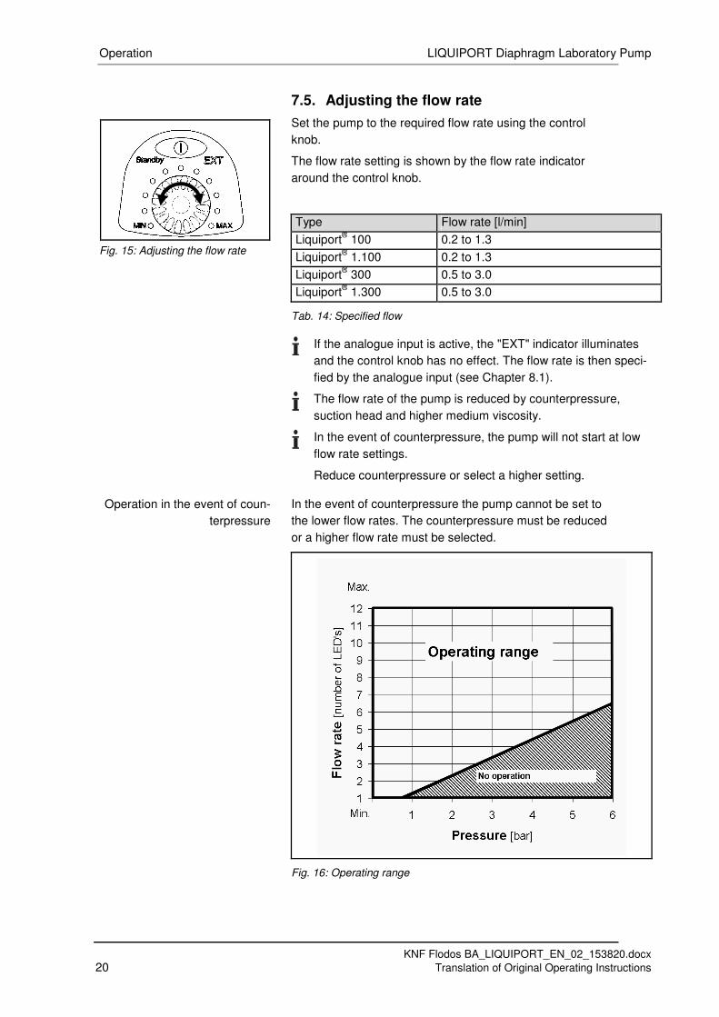
7.5. Adjusting the flow rate
Set the pump to the required flow rate using the control
knob.
The flow rate setting is shown by the flow rate indicator
around the control knob.
Type Flow rate [l/min]
Liquiport® 100 0.2 to 1.3
Liquiport® 1.100 0.2 to 1.3
Liquiport® 300 0.5 to 3.0
Liquiport® 1.300 0.5 to 3.0
Tab. 14: Specified flow
If the analogue input is active, the "EXT" indicator illuminates
and the control knob has no effect. The flow rate is then speci-
fied by the analogue input (see Chapter 8.1).
The flow rate of the pump is reduced by counterpressure,
suction head and higher medium viscosity.
In the event of counterpressure, the pump will not start at low
flow rate settings.
Reduce counterpressure or select a higher setting.
In the event of counterpressure the pump cannot be set to
the lower flow rates. The counterpressure must be reduced
or a higher flow rate must be selected.
Fig. 16: Operating range
Fig. 15: Adjusting the flow rate
Operation in the event of coun-
terpressure

LIQUIPORT Diaphragm Laboratory Pump RC version – external actuation
KNF Flodos BA_LIQUIPORT_EN_02_153820.docx
Translation of Original Operating Instructions 21
8. RC version – external actuation
External actuation functions are available only in the RC ver-
sion.
Connection details and technical data are provided in Chap-
ters 4.6 and 6.3.
8.1. External actuation analogue input
The analogue input can be used to externally specify a
pump flow rate from (0%) 15% to 100%.
The analogue input must be activated by connecting the RC
cable.
With RC cable connect white lead (jumper) to grey lead
(ground) or with RC connector connect pin 2 to pin 5
(see Fig. 17).
If external actuation is switched on, this is indicated at
the pump by the illuminated "EXT" symbol (see Fig. 18).
When the analogue input is active, the pump can be started
only if a valid analogue signal is present.
The control knob is deactivated. Manual flow rate entry is
blocked.
Control signals
Name
Voltage range 0 – 10V
On threshold ≥ 0.2V
Off threshold ≤ 0.2V
Tab. 15: Analogue input signals
Fig. 19: Analogue input range
Activating the analogue input
1 Brown (analogue input)
2 White (external jumper)
3 Blue
4 Black
5 Grey (ground)
6 Jumper
7 Analogue signal 0-10V
Fig. 17: RC cable jumper
Fig. 18: "EXT" indication
RC version – external actuation LIQUIPORT Diaphragm Laboratory Pump
KNF Flodos BA_LIQUIPORT_EN_02_153820.docx
22 Translation of Original Operating Instructions
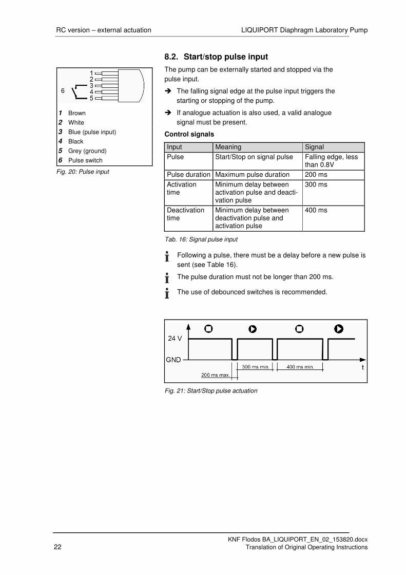
8.2. Start/stop pulse input
The pump can be externally started and stopped via the
pulse input.
The falling signal edge at the pulse input triggers the
starting or stopping of the pump.
If analogue actuation is also used, a valid analogue
signal must be present.
Control signals
Input Meaning Signal
Pulse Start/Stop on signal pulse Falling edge, less than 0.8V
Pulse duration Maximum pulse duration 200 ms
Activation time
Minimum delay between activation pulse and deacti-vation pulse
300 ms
Deactivation time
Minimum delay between deactivation pulse and activation pulse
400 ms
Tab. 16: Signal pulse input
Following a pulse, there must be a delay before a new pulse is
sent (see Table 16).
The pulse duration must not be longer than 200 ms.
The use of debounced switches is recommended.
Fig. 21: Start/Stop pulse actuation
1 Brown
2 White
3 Blue (pulse input)
4 Black
5 Grey (ground)
6 Pulse switch
Fig. 20: Pulse input

LIQUIPORT Diaphragm Laboratory Pump RC version – external actuation
KNF Flodos BA_LIQUIPORT_EN_02_153820.docx
Translation of Original Operating Instructions 23
8.3. Foot switch
With the RC version, the
Liquiport® pulse foot switch (KNF Id. no. 155872) can be
connected to the RC connector as an accessory.
When the foot switch is operated, the pulse signal is
connected to ground, which switches the pump on.
If it is operated again the pump is switched off.
The minimum switching times must be taken into consideration
when the foot switch is operated (see chapter 8.2).
The pump can also be switched on or off using the Start/Stop
button at any time.
8.4. Digital output
The current operating status of the pump can be read out via
the digital output.
The open collector is only switched on if the pump is trans-
ferring.
The open collector output is internally connected to the collec-
tor of an NPN transistor (BC817-40) and to the internal 24V
feed via a diode.
A maximum of 24V may be connected to the output.
The maximum current via the open collector must be limited to
10mA.
Fig. 22: Foot switch
1 Brown
2 White
3 Blue
4 Black (digital output)
5 Grey (ground)
6 Open collector
Fig. 23: Digital output

Servicing LIQUIPORT Diaphragm Laboratory Pump
KNF Flodos BA_LIQUIPORT_EN_02_153820.docx
24 Translation of Original Operating Instructions
9. Servicing
9.1. Servicing schedule Component Servicing interval
Pump - Regular inspection for external damage or leaks
Pump head - Clean if the flow rate decreases, the pump does not work or no vacuum is created.
- Replace parts if necessary (see Chapter 11).
Pump diaphragm - Replace pump diaphragm if the pumping capacity decreases or a leak occurs
- Replace pump diaphragm in the event of repeated head installation.
Intake filter (accessory)
- Change if soiled.
Tab. 17: Servicing schedule
9.2. Cleaning
Flushing the pump
If pumping aggressive media, KNF recommends flushing
the pump with a neutral fluid under atmospheric condi-
tions for a few minutes before switching off, to extend
the service life of valves and diaphragm.
Cleaning the pump
Wipe the outside of the pump with a soft dry cloth.
Solvent should only be used for cleaning if the head ma-
terials and the pump housing are not affected (ensure
that material is resistant).
If there is compressed air available, blow off compo-
nents.
Cleaning the pump head
The pump head should only be cleaned if the pump is no
longer working properly (no suction, inadequate flow rate or
reverse suction of the pumped medium).
Or of the pump head cannot be cleaned satisfactorily by flush-
ing.
Remove, clean and re-install pump head (see Chapter
9.3).

LIQUIPORT Diaphragm Laboratory Pump Servicing
KNF Flodos BA_LIQUIPORT_EN_02_153820.docx
Translation of Original Operating Instructions 25
9.3. Cleaning/replacing valve plates and pump diaphragm
Pump must be switched off and mains plug removed
from the socket.
The pump must be free of any hazardous substanc-
es.
Hoses must be disconnected from the pump head.
Liquiport
® 100 KT / TT, Liquiport
® 1.100 KT / TT
Qty. Tools/materials
1 Torx T 20 screwdriver No. 2
1 Spare parts kit (see Chapter 11)
Liquiport® 100 FT, Liquiport
® 1.100 FT
Qty. Tools/materials
1 Phillips screwdriver No. 2
1 Spare parts kit (see Chapter 11)
Liquiport® 300 KT / TT, Liquiport
® 1.300 KT / TT
Qty. Tools/materials
1 T20 Torx screwdriver
1 Spare parts kit (see Chapter 11)
Liquiport® 300 FT, Liquiport
® 1.300 FT
Qty. Tools/materials
1 Phillips screwdriver No. 2
1 Spare parts kit (see Chapter 11) Tab. 18: Tools / materials
In order to provide optimum pump head tightness after
opening the pump head it is advisable to replace the
rolled diaphragm, the valve plates, the resonating dia-
phragm and the O-rings at the same time.
WARNING
Health hazard due to dangerous
substances in the pump
Depending on the medium pumped, risk of caustic
burns or poisoning.
Use protective equipment if necessary, e.g.
protective gloves, goggles.
Flush pump with a neutral fluid and then pump
empty.
Prior requirements
Tools and materials
Information on procedure

Servicing LIQUIPORT Diaphragm Laboratory Pump
KNF Flodos BA_LIQUIPORT_EN_02_153820.docx
26 Translation of Original Operating Instructions
Dismantling the pump head
Fig. 24: Liquiport
®100
Fig. 25: Liquiport
®300
Loosen the four head screws (1) and remove the entire 1.
head.

LIQUIPORT Diaphragm Laboratory Pump Servicing
KNF Flodos BA_LIQUIPORT_EN_02_153820.docx
Translation of Original Operating Instructions 27
Removing the valves and seals
Lift the connecting plate (5) from the intermediate plate 2.
(7).
Remove the valve plate (6) from the intermediate plate 3.
(7).
Remove the resonating diaphragm (3) from the connect-4.
ing plate (5).
Remove the O-rings (4) from the cover plate. 5.
Carefully grip the rolled diaphragm (8) and unscrew it by 6.
rotating anticlockwise. Remove the washers (9) and
make sure that no washers 9 fall into the pump housing.
It is advisable to replace the rolled diaphragm (8).
Cleaning the parts
Clean rolled diaphragm (8), O-ring (4), resonating dia-7.
phragm (3), valve plate (6), intermediate plate (7) and
connecting plate (5) with a cloth and then blow off with
compressed air.
Mounting the rolled diaphragm
Slide the same number of washers (9) fitted between the 8.
diaphragm and the connecting rod over the connecting
thread of the diaphragm (8). Make sure that no washer
(9) falls into the pump housing.
Screw in the rolled diaphragm (8). 9.
By lightly pressing on the rolled diaphragm push the 10.
ridge on the underside of the rolled diaphragm into the
groove of the housing.
Mounting the valve plates
Place the dust-free valve plates (6) into the intermediate 11.
plate (7) in the correct position.
Mounting the pump head
Place the resonating diaphragm (3) into the connecting 12.
plate (5) and cover with the cover plate (2) fitted with the
new O-ring.
All visible lines on the intermediate plate (7), the con-13.
necting plate (5) and the head plate (2) must be in line
with each other.
Insert the four head screws (1) in the through holes of 14.
the pump head.
The head plate (2) must be positioned so that the flow 15.
direction arrows on the head plate coincide with the
connections on the connecting plate (5).
Place the pump head onto the pump housing and tight-16.
en the four head screws (1) crosswise. Maximum torque
is 1.5 Nm.

Troubleshooting LIQUIPORT Diaphragm Laboratory Pump
KNF Flodos BA_LIQUIPORT_EN_02_153820.docx
28 Translation of Original Operating Instructions
10. Troubleshooting
CAUTION
Safety note
Always remove the mains plug
from the socket before carrying
out any work on the pump.
WARNING
Health hazard due to dangerous
substances in the pump.
Depending on the medium pumped, risk of caustic
burns or poisoning.
Use protective equipment if necessary, e.g.
protective gloves, goggles.
Rinse the pump with a neutral liquid and pump
empty.
Inspect the pump (see Tab. 19 and 20).
Pump does not work
Cause Fault remedy
Pump not connected to mains power supply.
Connect pump to mains supply.
No mains supply. Check room fuse and switch on if necessary.
Connections or pipes are blocked.
Check pipes and connections.
Remove blockage.
External valve is closed or filter is blocked.
Check external valves and filters.
Worn diaphragm or valve plates / seals.
Replace diaphragm and valve plates/seals (see Chapter 9.3).
External actuation connected without a signal
Check external actuation signal.
Pump overload protection has tripped.
- Flow rate indicator flashing
- Standby indicator not illumi-nated
Pump unable to build up counterpressure.
Pump transferring against pressure that is too high.
Reduce pressure in system.
Reduce flow rate.
Pump overload protection has tripped.
- Flow rate indicator flashing
- The standby indicator illumi-nates
Pump unable to build up counterpressure.1)
Pump transferring against pressure that is too high.
Reduce pressure in system.
Reduce flow rate.
Restart the pump. Tab. 19: Pump not transferring 1)
Maximum pressure build-up depends on flow rate setting.
Please note: Pump not protected from overpressure.
Information on procedure

LIQUIPORT Diaphragm Laboratory Pump Troubleshooting
KNF Flodos BA_LIQUIPORT_EN_02_153820.docx
Translation of Original Operating Instructions 29
Low flow rate, pressure or vacuum
The pump does not achieve the performance stated in the Technical Data or on the data sheet.
Cause Fault remedy
Presence of positive pressure on the pressure side with simul-taneous vacuum or positive pressure on the suction side.
Change pressure conditions.
Cross-section of hydraulic lines or connectors too narrow or restricted.
Disconnect the pump from the system and determine output values.
Remove restriction (e.g. valve) if necessary.
If applicable, use larger-diameter lines or connectors.
Leaks in connections, lines or pump head.
Eliminate leaks.
Connections or lines completely or partially obstructed.
Check pipes and connections.
Remove any parts or particles causing blockages.
Soiled pump head components. Clean head components.
Worn diaphragm or valve plates/seals.
Replace diaphragm and valve plates/seals (see Chapter 9.3).
Materials chemically damaged by pumped media.
Select a type of material that is resistant and suitable.
Tab. 20: Low flow rate, pressure or vacuum
Fault cannot be rectified
If you are unable to identify any of the above causes, please
send the pump to KNF customer services (see address on
last page).
Flush the pump to clear the pump head of any hazard-1.
ous or aggressive fluids (see Chapter 9.2).
Dismantle the pump. 2.
Clean the pump (see Chapter 9.2). 3.
Send the pump with completed decontamination decla-4.
ration (see Chapter 12) to KNF customer services, stat-
ing the nature of the pumped medium.

Spare parts and accessories LIQUIPORT Diaphragm Laboratory Pump
KNF Flodos BA_LIQUIPORT_EN_02_153820.docx
30 Translation of Original Operating Instructions
11. Spare parts and accessories
11.1. Spare parts
Spare parts Order No.
Liquiport® 100 spare parts kit, KT head 065262
Liquiport® 100 spare parts kit, TT head 065262
Liquiport® 100 spare parts kit, FT head 152631
Liquiport® 1.100 spare parts kit, KT
head 065262
Liquiport® 1.100 spare parts kit, TT
head 065262
Liquiport® 1.100 spare parts kit, FT
head 152631
Liquiport® 300 spare parts kit, KT head 068691
Liquiport® 300 spare parts kit, TT head 068691
Liquiport® 300 spare parts kit, FT head 151902
Liquiport® 1.300 spare parts kit, KT
head 069278
Liquiport® 1.300 spare parts kit, TT
head 069278
Liquiport® 1.300 spare parts kit, FT
head 151903
Tab. 21: Spare parts
11.2. Accessories
Connection nipples Order No.
Screw-in nipple G NPT1/8" ID8 ETFE 153751
Screw-in nipple seal FFKM 155604
Screw-in nipple G NPT3/8" ID12 ETFE
153753
Screw-in nipple seal FFKM 155602 Tab. 22: Connection nipples
Foot switch Order No.
Liquiport® pulse foot switch 155872
Tab. 23: Foot switch
Fasteners Order No.
Tripod holder 160474
Mounting plate 160473 Tab. 24: Fasteners

LIQUIPORT Diaphragm Laboratory Pump Decontamination declaration
KNF Flodos BA_LIQUIPORT_EN_02_153820.docx
Translation of Original Operating Instructions 31
12. Decontamination declaration
KNF shall only undertake to repair the pump on condition that
the customer provides certification of the transferred media
and the cleaning of the pump (decontamination declaration).
Copy this page.
Enter the pump model, the Serial No. and the transferred
media in the form below and send the signed form together
with the flushed and cleaned pump to KNF customer ser-
vices (see address on last page)
Customer decontamination declaration for repair order
We confirm that the pump below has been used to pump the
following media, and that the pump has been flushed and
cleaned.
Pump model
Serial No.
Pumped media
The pump does not contain aggressive, biological, radioac-
tive, poisonous, or other dangerous media.
Company Date/Signature