nga standardization document · 16 december 2010 ... nga.stnd.0025-1_1.0 sensor independent derived...
TRANSCRIPT
NGA.STND.0025-2_1.0 2011-08-01
NGA STANDARDIZATION DOCUMENT
SENSOR INDEPENDENT DERIVED DATA (SIDD)
Volume 2,
NITF File Format Description Document
Specification of the placement of SIDD data products
in the NITF V2.1 image file format.
(2011-08-01)
Version 1.0
NATIONAL CENTER FOR GEOSPATIAL INTELLIGENCE STANDARDS

NGA.STND.0025-2_1.0 2011-08-01
i
CONTACTS
The following points of contact are provided for assistance in understanding the contents of this
standard.
NGA/AEX
P-001
12310 Sunrise Valley Drive
Reston, VA 20191-3449
(703) 755-5951
NGA/NCGIS
P-106
12310 Sunrise Valley Drive
Reston, VA 20191-3449
(703) 814-4564

NGA.STND.0025-2_1.0 2011-08-01
ii
Change Log
Date Version Description DR/CA Developer
01 AUG 2011 1.0.0 Initial publication. N/A
TBR/TBD Log
Page Number TBD/TBR Description Date Addressed
NGA.STND.0025-2_1.0 2011-08-01
iii
FOREWORD
The suite of Sensor Independent Derived Data (SIDD) standardization documents describe the implementation of various data products generated by Synthetic Aperture Radar (SAR) systems and their data processing elements. SAR-derived image products, and their associated metadata, are grouped around common tasks for downstream users. The SIDD documentation provides specifications for these common tasks which are designed to support basic exploitation, geographic measurements, and proper visual display. Additionally, the documentation specifies the SIDD supported coordinate systems and product image pixel arrays. The real utility of SAR image collection is in the products and measurements that may be derived from it. The quality of the pixel array data along with the set of metadata provided are critical in generating the derived products. The “sensor independence” of the SIDD product refers to the ability of the allowed pixel array and metadata options to accurately describe the image products from different sensors and data processing systems. Sensor independence does NOT mean that all products have the same format for the pixel array or the same set of metadata parameters. The SIDD documentation has been organized into three volumes: Volume 1 is the description needed by producers of SAR data to design a SIDD product that contains the image data and the set of metadata that describe it. Volume 2 defines the placement of SIDD data products in the NITF V2.1 image file format. Also provided is the description needed by users of SIDD products to read and properly extract the SIDD data components from a SIDD NITF product file. Volume 3 defines the placement of SIDD data products in the GeoTIFF 1.0 image file format. Also provided is the description needed by users of SIDD products to read and properly extract the SIDD data components from a SIDD GeoTIFF product file. A companion suite of standardization documents, collectively known as Sensor Independent Complex Data (SICD), describe standardized complex image products and measurements from which SIDD products may be derived. The SICD and SIDD documentation and associated XML artifacts are available on the National System For Geospatial-Intelligence (NSG) Standards Registry (https://nsgreg.nga.mil).

NGA.STND.0025-2_1.0 2011-08-01
iv
Table of Contents
CONTACTS .............................................................................................................................................................. I
CHANGE LOG ......................................................................................................................................................... II
LIST OF TABLES ...................................................................................................................................................... V
LIST OF FIGURES ..................................................................................................................................................... V
1 INTRODUCTION ............................................................................................................................................. 1
1.1 SCOPE ............................................................................................................................................................. 1
1.2 APPLICABLE DOCUMENTS ................................................................................................................................... 1
2 SIDD PRODUCTS IN NITF 2.1 FORMAT ........................................................................................................... 2
2.1 CAPABILITIES AND LIMITATIONS ........................................................................................................................... 2
2.2 SIDD NITF 2.1 FILE CONTAINER METADATA ......................................................................................................... 2
2.2.1 SIDD NITF 2.1 File Header Description ..................................................................................................... 2
2.2.2 SIDD NITF 2.1 Image Sub-header Description .......................................................................................... 7
2.2.3 SIDD XML DES Description ..................................................................................................................... 11
2.2.4 SICD XML DES Description ...................................................................................................................... 13
2.3 SIDD NITF 2.1 SIDD PRODUCT METADATA........................................................................................................ 13
2.3.1 Image Product Metadata ....................................................................................................................... 13
2.3.2 Input Image Metadata ........................................................................................................................... 14
2.4 SIDD PRODUCT IMAGE PIXEL DATA .................................................................................................................... 14
2.4.1 Pixel Types .............................................................................................................................................. 14
2.4.2 Segmentation ......................................................................................................................................... 15
2.4.3 Legends .................................................................................................................................................. 19
2.4.4 JPEG 2000 Compression ......................................................................................................................... 20
2.5 SIDD NITF 2.1 FILE CONTAINER ORGANIZATION .................................................................................................. 21
2.5.1 Single Input Image - Single Product Image ............................................................................................ 22
2.5.2 Multiple Input Images – Single Product Image ...................................................................................... 23
2.5.3 Single Input Image – Multiple Product Images ...................................................................................... 23
2.5.4 Single Input Image – Single Product Image Requiring Segmentation .................................................... 24
2.5.5 Multiple Input Image – Multiple Product Images Requiring Segmentation .......................................... 25
APPENDIX A - TERMS & DEFINITION ............................................................................................................. 27
APPENDIX B - JPEG 2000 CODESTREAM DEFINITION ..................................................................................... 28
B.1 JPEG 2000 CODESTREAM LAYOUT .................................................................................................................... 28
B.2 JPEG 2000 IMAGE DATA ................................................................................................................................. 30
B.2.1 Visually Lossless Compression ................................................................................................................ 31
B.2.2 Numerically Lossless Compression ......................................................................................................... 31
B.2.3 Layer Ordering ....................................................................................................................................... 31
B.3 JPEG 2000 SEGMENT MARKER DEFINITIONS ....................................................................................................... 31
B.3.1 JPEG 2000 Main Header ......................................................................................................................... 31

NGA.STND.0025-2_1.0 2011-08-01
v
B.3.2 JPEG 2000 Tile Header ........................................................................................................................... 34
List of Tables
TABLE 1-1 GOVERNMENT DOCUMENTS AND PUBLICATIONS ....................................................................................................... 1
TABLE 1-2 OTHER APPLICABLE DOCUMENTS ............................................................................................................................ 1
TABLE 2-1 SIDD NITF 2.1 FILE HEADER DEFINITION ................................................................................................................ 2
TABLE 2-2 NITF 2.1 SECURITY FIELDS .................................................................................................................................... 4
TABLE 2-3 SIDD NITF 2.1 IMAGE SUB-HEADER DEFINITION ...................................................................................................... 8
TABLE 2-4 SIDD XML DES DESCRIPTION ............................................................................................................................. 11
TABLE 2-5 SICD XML DES DESCRIPTION ............................................................................................................................. 13
TABLE 2-6 NITF 2.1 IMAGE SUB-HEADER POPULATION FOR SUPPORTED PIXEL TYPE .................................................................... 15
TABLE 2-7 SIDD NITF 2.1 FILE CONTAINER METADATA POPULATION INSTRUCTIONS FOR LEGENDS ................................................ 19
TABLE 2-8 SIDD NITF 2.1 IMAGE SUB-HEADER DIFFERENCES FOR JPEG 2000 COMPRESSION ...................................................... 20
TABLE A-1 TERMS & DEFINITIONS ....................................................................................................................................... 27
TABLE B-1 START OF CODESTREAM (SOC) MARKER ............................................................................................................... 32
TABLE B-2 IMAGE & TILE SIZE (SIZ) MARKER SEGMENT .......................................................................................................... 32
TABLE B-3 CODING STYLE DEFAULT (COD) MARKER SEGMENT ................................................................................................ 33
TABLE B-4 QUANTIZATION DEFAULT (QCD) MARKER SEGMENT ............................................................................................... 33
TABLE B-5 TILE PART LENGTH (TLM) MARKER SEGMENT ........................................................................................................ 34
TABLE B-6 START OF TILE PART (SOT) MARKER SEGMENT ....................................................................................................... 34
TABLE B-7 PACKET LENGTH TILE PART (PLT) MARKER SEGMENT .............................................................................................. 34
TABLE B-8 START OF DATA (SOD) MARKER .......................................................................................................................... 35
TABLE B-9 END OF CODESTREAM (EOC) MARKER .................................................................................................................. 35
List of Figures
FIGURE 2.4-1 EXAMPLE NITF 2.1 IMAGE SEGMENTATION FOR MULTIPLE IMAGE PRODUCT [RRRRR IS DEFINED AS THE ZERO PADDED
VERSION OF NUMROWSLIMIT(K)] ............................................................................................................................... 18
FIGURE 2.5-1 - SIDD NITF 2.1 FILE CONTAINER ORGANIZATION - SINGLE INPUT IMAGE/SINGLE PRODUCT IMAGE ............................ 22
FIGURE 2.5-2 - SIDD NITF 2.1 W/JPEG 2000 COMPRESSION SINGLE INPUT - SINGLE PRODUCT IMAGE EXAMPLE ........................... 23
FIGURE 2.5-3 - SIDD NITF 2.1 FILE CONTAINER ORGANIZATION - MULTIPLE INPUT IMAGES/SINGLE PRODUCT IMAGE ...................... 23
FIGURE 2.5-4 - SIDD NITF 2.1 FILE CONTAINER ORGANIZATION - SINGLE INPUT IMAGE/MULTIPLE PRODUCT IMAGES ...................... 24
FIGURE 2.5-5 - SIDD NITF 2.1 FILE CONTAINER ORGANIZATION - SINGLE INPUT IMAGE/SINGLE PRODUCT IMAGE REQUIRING
SEGMENTATION ....................................................................................................................................................... 25
FIGURE 2.5-6 - SIDD NITF 2.1 FILE CONTAINER ORGANIZATION - MULTIPLE INPUT IMAGE/MULTIPLE PRODUCT IMAGE REQUIRING
SEGMENTATION ....................................................................................................................................................... 26
FIGURE B.1 JPEG 2000 CODESTREAM HIGH-LEVEL LAYOUT .................................................................................................... 29
FIGURE B.2 JPEG 2000 MAIN HEADER LAYOUT .................................................................................................................... 30

NGA.STND.0025-2_1.0 2011-08-01
vi
FIGURE B.3 JPEG 2000 TILE HEADER LAYOUT ...................................................................................................................... 30
NGA.STND.0025-2_1.0 2011-08-01
1
1 Introduction
1.1 Scope
The Sensor Independent Derived Data (SIDD) NITF File Format Description Document
specifies the placement of derived image products into the NITF 2.1 file-format container. For
this container file format, the following topics are covered:
Capabilities & limitations
File container organization
File container metadata
SIDD product metadata
SIDD product image pixel data
The file name format for SIDD products is outside the scope of this standard and is left to the
program-specific implementation profile.
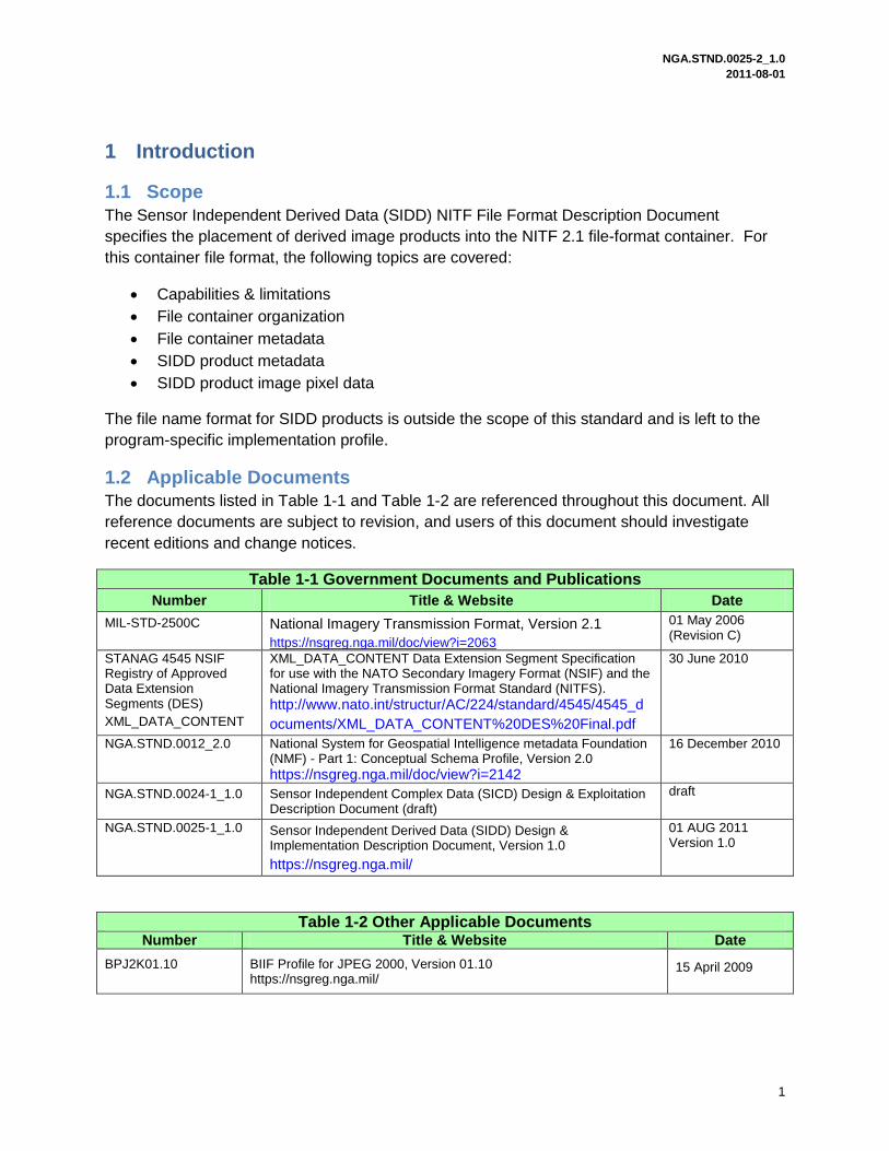
1.2 Applicable Documents
The documents listed in Table 1-1 and Table 1-2 are referenced throughout this document. All
reference documents are subject to revision, and users of this document should investigate
recent editions and change notices.
Table 1-1 Government Documents and Publications
Number Title & Website Date
MIL-STD-2500C National Imagery Transmission Format, Version 2.1
https://nsgreg.nga.mil/doc/view?i=2063
01 May 2006 (Revision C)
STANAG 4545 NSIF Registry of Approved Data Extension Segments (DES)
XML_DATA_CONTENT
XML_DATA_CONTENT Data Extension Segment Specification for use with the NATO Secondary Imagery Format (NSIF) and the National Imagery Transmission Format Standard (NITFS).
http://www.nato.int/structur/AC/224/standard/4545/4545_d
ocuments/XML_DATA_CONTENT%20DES%20Final.pdf
30 June 2010
NGA.STND.0012_2.0 National System for Geospatial Intelligence metadata Foundation (NMF) - Part 1: Conceptual Schema Profile, Version 2.0
https://nsgreg.nga.mil/doc/view?i=2142
16 December 2010
NGA.STND.0024-1_1.0 Sensor Independent Complex Data (SICD) Design & Exploitation Description Document (draft)
draft
NGA.STND.0025-1_1.0 Sensor Independent Derived Data (SIDD) Design & Implementation Description Document, Version 1.0
https://nsgreg.nga.mil/
01 AUG 2011 Version 1.0
Table 1-2 Other Applicable Documents Number Title & Website Date
BPJ2K01.10 BIIF Profile for JPEG 2000, Version 01.10 https://nsgreg.nga.mil/
15 April 2009

NGA.STND.0025-2_1.0 2011-08-01
2
2 SIDD Products in NITF 2.1 Format The purpose of this section is to define the following items for SIDD NITF 2.1 products:
Capabilities and limitations of NITF 2.1 file container
SIDD NITF 2.1 file container metadata
Placement of SIDD product metadata in NITF 2.1 container
Placement of SIDD product image data in NITF 2.1 container
SIDD NITF 2.1 file container organization
2.1 Capabilities and Limitations
The NITF 2.1 container format is capable of handling a wide array of SIDD products ranging
from single-image products generated from a single SICD input to multiple-image products
generated from multiple SICD inputs. Additionally, SIDD makes use of the NITF 2.1 file
container‟s capability to support very large, multi-image products.
2.2 SIDD NITF 2.1 File Container Metadata
SIDD NITF 2.1 files are composed of four basic components: a file header, an image sub-
header, SIDD Data Extension Segment (DES), and SICD DES (if available). The following
sections provide population instructions for each of the container metadata blocks.
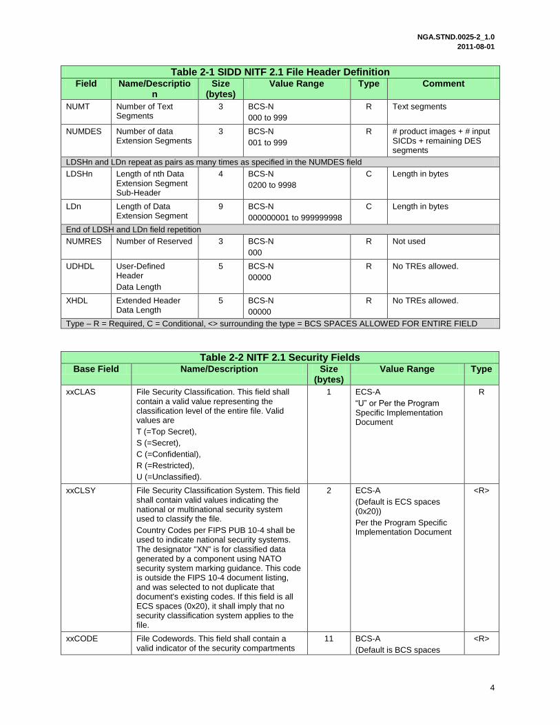
2.2.1 SIDD NITF 2.1 File Header Description
The purpose of this section is to define the population instructions for each field in the NITF 2.1
file header. The file header describes the file layout and other high-level information.
Population information is found in Table 2-1 and Table 2-2.
Table 2-1 SIDD NITF 2.1 File Header Definition Field Name/Descriptio
n Size
(bytes) Value Range Type Comment
FHDR File Profile Name 4 BCS-A
“NITF"
R Per MIL-STD-2500c
FVER File Version 5 BCS-A
“02.10”
R NITF Version 2.1
CLEVEL Complexity Level 2 BCS-A
03, 05, 06, 07 or 09
R Per MIL-STD-2500c Table A-10
STYPE Standard Type 4 BCS-N
“BF01”
R Fixed value
OSTAID Originating Station ID
10 BCS-A
This field shall contain a meaningful value; it shall not be filled with BCS spaces (0x20)
R Per the Product Specific Implementation Document
FDT File Date and Time 14 BCS-N
CCYYMMDDhhmmss
R File creation UTC date and time
FTITLE File Title 80 ECS-A
“SIDD: <ProductName>”
<R> “SIDD: <ProductName>” where ProductName comes from SIDD.ProductCreation.ProductName. After SIDD colon

NGA.STND.0025-2_1.0 2011-08-01
3
Table 2-1 SIDD NITF 2.1 File Header Definition Field Name/Descriptio
n Size
(bytes) Value Range Type Comment
space fill in with the 1st 74 characters of ProductName
Security Tags
Use “FS” prefix for Tag
167 As defined in Table 2-2 R
FSCOP File Copy Number 5 BCS-N
00000 = No tracking of numbered file copies
R Not tracked Per MIL-STD-2500c
FSCPYS File Number of Copies
5 BCS-N
00000 = No tracking of numbered file copies
R Not tracked Per MIL-STD-2500c
ENCRYP Encryption 1 BCS-N
0
R No Encryption
FBKGC File Background Color
3 Unsigned binary integer
Default: 000 (0x00, 0x00, 0x00)
R Default background color is black
ONAME Originator‟s Name 24 ECS-A
24 ECS characters
<R> Per the Product Specific Implementation Document
OPHONE Originator‟s Phone 18 ECS-A
24 ECS characters
<R> Per the Product Specific Implementation Document
FL File Length 12 BCS-N
Generate
R Number of bytes
HL NITF File Header Length
6 BCS-N
Generate
R Number of bytes in the header
NUMI Number of Image Segments
3 BCS-N
001 to 999
R See Sections 2.4.2 and 2.4.3
LISHn and LIn repeat as pairs as many times as specified in the NUMI field LISHn Length of Image
Sub-Header.
This field shall occur as many times as specified in the NUMI field. Note: The largest image sub-header is limited to 999998 (10**6 -2) bytes.
6 BCS-N
000439 to 9999998
Generate
C Per MIL-STD-2500c
LIn Length of nth Image Segment. This field shall occur as many times as specified in the NUMI field. Note: The largest image is limited to 9,999,999,998 (10**10 -2) bytes.
10 BCS-N
0000000001 to
9999999998
Generate
C See Sections 2.4.2 and 2.4.3
End of LISH and LIn field repetition NUMS Number of graphic
Segments 3 BCS-N
000 to 999
R Graphics segments
NUMX Reserved 3 BCS-N
000
R Reserved
NGA.STND.0025-2_1.0 2011-08-01
4
Table 2-1 SIDD NITF 2.1 File Header Definition Field Name/Descriptio
n Size
(bytes) Value Range Type Comment
NUMT Number of Text Segments
3 BCS-N
000 to 999
R Text segments
NUMDES Number of data Extension Segments
3 BCS-N
001 to 999
R # product images + # input SICDs + remaining DES segments
LDSHn and LDn repeat as pairs as many times as specified in the NUMDES field LDSHn Length of nth Data
Extension Segment Sub-Header
4 BCS-N
0200 to 9998
C Length in bytes
LDn Length of Data Extension Segment
9 BCS-N
000000001 to 999999998
C Length in bytes
End of LDSH and LDn field repetition NUMRES Number of Reserved 3 BCS-N
000
R Not used
UDHDL User-Defined Header
Data Length
5 BCS-N
00000
R No TREs allowed.
XHDL Extended Header Data Length
5 BCS-N
00000
R No TREs allowed.
Type – R = Required, C = Conditional, <> surrounding the type = BCS SPACES ALLOWED FOR ENTIRE FIELD
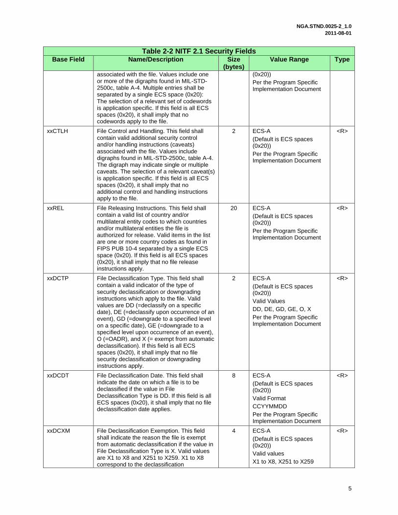
Table 2-2 NITF 2.1 Security Fields Base Field Name/Description Size
(bytes) Value Range Type
xxCLAS File Security Classification. This field shall contain a valid value representing the classification level of the entire file. Valid values are
T (=Top Secret),
S (=Secret),
C (=Confidential),
R (=Restricted),
U (=Unclassified).
1 ECS-A
“U” or Per the Program Specific Implementation Document
R
xxCLSY File Security Classification System. This field shall contain valid values indicating the national or multinational security system used to classify the file.
Country Codes per FIPS PUB 10-4 shall be used to indicate national security systems. The designator "XN" is for classified data generated by a component using NATO security system marking guidance. This code is outside the FIPS 10-4 document listing, and was selected to not duplicate that document's existing codes. If this field is all ECS spaces (0x20), it shall imply that no security classification system applies to the file.
2 ECS-A
(Default is ECS spaces (0x20))
Per the Program Specific Implementation Document
<R>
xxCODE File Codewords. This field shall contain a valid indicator of the security compartments
11 BCS-A
(Default is BCS spaces
<R>
NGA.STND.0025-2_1.0 2011-08-01
5
Table 2-2 NITF 2.1 Security Fields Base Field Name/Description Size
(bytes) Value Range Type
associated with the file. Values include one or more of the digraphs found in MIL-STD-2500c, table A-4. Multiple entries shall be separated by a single ECS space (0x20): The selection of a relevant set of codewords is application specific. If this field is all ECS spaces (0x20), it shall imply that no codewords apply to the file.
(0x20))
Per the Program Specific Implementation Document
xxCTLH File Control and Handling. This field shall contain valid additional security control and/or handling instructions (caveats) associated with the file. Values include digraphs found in MIL-STD-2500c, table A-4. The digraph may indicate single or multiple caveats. The selection of a relevant caveat(s) is application specific. If this field is all ECS spaces (0x20), it shall imply that no additional control and handling instructions apply to the file.
2 ECS-A
(Default is ECS spaces (0x20))
Per the Program Specific Implementation Document
<R>
xxREL File Releasing Instructions. This field shall contain a valid list of country and/or multilateral entity codes to which countries and/or multilateral entities the file is authorized for release. Valid items in the list are one or more country codes as found in FIPS PUB 10-4 separated by a single ECS space (0x20). If this field is all ECS spaces (0x20), it shall imply that no file release instructions apply.
20 ECS-A
(Default is ECS spaces (0x20))
Per the Program Specific Implementation Document
<R>
xxDCTP File Declassification Type. This field shall contain a valid indicator of the type of security declassification or downgrading instructions which apply to the file. Valid values are DD (=declassify on a specific date), DE (=declassify upon occurrence of an event), GD (=downgrade to a specified level on a specific date), GE (=downgrade to a specified level upon occurrence of an event), O (=OADR), and X (= exempt from automatic declassification). If this field is all ECS spaces (0x20), it shall imply that no file security declassification or downgrading instructions apply.
2 ECS-A
(Default is ECS spaces (0x20))
Valid Values
DD, DE, GD, GE, O, X
Per the Program Specific Implementation Document
<R>
xxDCDT File Declassification Date. This field shall indicate the date on which a file is to be declassified if the value in File Declassification Type is DD. If this field is all ECS spaces (0x20), it shall imply that no file declassification date applies.
8 ECS-A
(Default is ECS spaces (0x20))
Valid Format
CCYYMMDD
Per the Program Specific Implementation Document
<R>
xxDCXM File Declassification Exemption. This field shall indicate the reason the file is exempt from automatic declassification if the value in File Declassification Type is X. Valid values are X1 to X8 and X251 to X259. X1 to X8 correspond to the declassification
4 ECS-A
(Default is ECS spaces (0x20))
Valid values
X1 to X8, X251 to X259
<R>

NGA.STND.0025-2_1.0 2011-08-01
6
Table 2-2 NITF 2.1 Security Fields Base Field Name/Description Size
(bytes) Value Range Type
exemptions found in DOD 5200.1-R, paragraphs 4- 202b(1) to (8) for material exempt from the 10-year rule. X251 to X259 correspond to the declassification exemptions found in DOD 5200.1-R, paragraphs 4- 301a(1) to (9) for permanently valuable material exempt from the 25-year declassification system. If this field is all ESC spaces (0x20), it shall imply that a file declassification exemption does not apply.
Per the Program Specific Implementation Document
xxDG File Downgrade. This field shall indicate the classification level to which a file is to be downgraded if the values in File Declassification Type are GD or GE. Valid values are S (=Secret), C (=Confidential), R (= Restricted). If this field contains an ECS space (0x20), it shall imply that file security downgrading does not apply.
1 ECS-A
(Default is ECS space (0x20))
Valid Values
S, C, R
Per the Program Specific Implementation Document
<R>
xxDGDT File Downgrade Date. This field shall indicate the date on which a file is to be downgraded if the value in File Declassification Type is GD. If this field is all ECS spaces (0x20), it shall imply that a file security downgrading date does not apply.
8 ECS-A
(Default is ECS spaces (0x20))
Valid Format
CCYYMMDD
Per the Program Specific Implementation Document
<R>
xxCLTX File Classification Text. This field shall be used to provide additional information about file classification to include identification of declassification or downgrading event if the values in File Declassification Type are DE or GE. It may also be used to identify multiple classification sources and/or any other special handling rules. Values are user defined free text. If this field is all ECS spaces (0x20), it shall imply that additional information about file classification does not apply.
43 ECS-A
(Default is ECS spaces (0x20))
Per the Program Specific Implementation Document
<R>
xxCATP File Classification Authority Type. This field shall indicate the type of authority used to classify the file. Valid values are O (= original classification authority), D (= derivative from a single source), and M (= derivative from multiple sources). If this field contains an ECS space (0x20), it shall imply that file classification authority type does not apply.
1 ECS-A
(Default is ECS space (0x20))
Per the Program Specific Implementation Document
<R>
xxCAUT File Classification Authority. This field shall identify the classification authority for the file dependent upon the value in File Classification Authority Type. Values are user defined free text which should contain the following information: original classification authority name and position or personal identifier if the value in File Classification Authority Type is O; title of the document or security classification guide used to classify the file if the value in File
40 ECS-A
(Default is ECS spaces (0x20))
Per the Program Specific Implementation Document
<R>

NGA.STND.0025-2_1.0 2011-08-01
7
Table 2-2 NITF 2.1 Security Fields Base Field Name/Description Size
(bytes) Value Range Type
Classification Authority Type is D; and Derive-Multiple if the file classification was derived from multiple sources and the value of the FSCATP field is M. In the latter case, the file originator will maintain a record of the sources used in accordance with existing security directives. One of the multiple sources may also be identified in File Classification Text if desired. If this field is all ECS spaces (0x20), it shall imply that no file classification authority applies.
xxCRSN File Classification Reason. This field shall contain values indicating the reason for classifying the file. Valid values are A to G. These correspond to the reasons for original classification per E.O. 12958, Section 1.5.(a) to (g). If this field contains an ECS space (0x20), it shall imply that no file classification reason applies.
1 ECS-A
(Default is ECS space (0x20))
Valid Values
A to G
Per the Program Specific Implementation Document
<R>
xxSRDT File Security Source Date. This field shall indicate the date of the source used to derive the classification of the file. In the case of multiple sources, the date of the most recent source shall be used. If this field is all ECS spaces (0x20), it shall imply that a file security source date does not apply.
8 ECS-A
(Default is ECS spaces (0x20))
Valid Format
CCYYMMDD
Per the Program Specific Implementation Document
<R>
xxCTLN File Security Control Number. This field shall contain a valid security control number associated with the file. The format of the security control number shall be in accordance with the regulations governing the appropriate security channel(s). If this field is all ECS spaces (0x20), it shall imply that no file security control number applies.
15 ECS-A
(Default is ECS spaces (0x20))
Per the Program Specific Implementation Document
<R>
For the File Header replace the xx prefix with FS (e.g., FSCLAS)
For the File Sub-Header replace the xx prefix with IS (e.g., ISCLAS)
For the DES replace the xx prefix with DES (e.g., DESCLAS)
Refer to MIL-STD-2500C Table A-1 for File Header and Table A-3 for Image Sub-Header for general description of all fields. Consult current security guidelines at time of production for proper entries.
Type – R = REQUIRED, C = CONDITIONAL, <> surrounding the type = BCS SPACES ALLOWED FOR ENTIRE FIELD
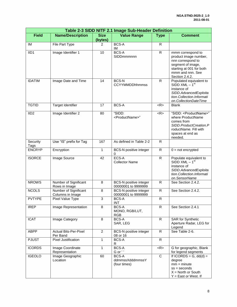
2.2.2 SIDD NITF 2.1 Image Sub-header Description
The purpose of this section is to define population instructions for the SIDD NITF 2.1 image sub-
header. It describes the image data that it corresponds to, image-data blocking information,
details about the image pixel data, and other additional information about the image. A NITF
2.1 image sub-header is present for each image segment in the file. Population information is
described in Table 2-3.
NGA.STND.0025-2_1.0 2011-08-01
8
Table 2-3 SIDD NITF 2.1 Image Sub-Header Definition Field Name/Description Size
(bytes) Value Range Type Comment
IM File Part Type 2 BCS-A IM
R
IID1 Image Identifier 1 10 BCS-A SIDDmmmnnn
R mmm correspond to product image number, nnn correspond to segment of image, starting at 001 for both mmm and nnn. See Section 2.4.2.
IDATIM Image Date and Time 14 BCS-N CCYYMMDDhhmmss
R Populated equivalent to SIDD XML – 1
st
instance of SIDD.AdvancedExploitation.Collection.Information.CollectionDateTime
TGTID Target Identifier 17 BCS-A
<R> Blank
IID2 Image Identifier 2 80 “SIDD: <ProductName>”
<R> “SIDD: <ProductName>” where ProductName comes from SIDD.ProductCreation.ProductName. Fill with
spaces at end as needed.
Security Tags
Use “IS” prefix for Tag 167 As defined in Table 2-2 R
ENCRYP Encryption 1 BCS-N positive integer 0
R 0 = not encrypted
ISORCE Image Source 42 ECS-A Collector Name
R Populate equivalent to SIDD XML – 1
st
instance of SIDD.AdvancedExploitation.Collection.Information.SensorName
NROWS Number of Significant Rows in Image
8 BCS-N positive integer 00000001 to 9999999
R See Section 2.4.2.
NCOLS Number of Significant Columns in Image
8 BCS-N positive integer 00000001 to 9999999
R See Section 2.4.2.
PVTYPE Pixel Value Type 3 BCS-A INT
R
IREP Image Representation 8 BCS-A MONO, RGB/LUT, RGB
R See Section 2.4.1
ICAT Image Category 8 BCS-A SAR, LEG
R SAR for Synthetic Aperture Radar, LEG for Legend
ABPP Actual Bits-Per-Pixel Per Band
2 BCS-N positive integer 08 or 16
R See Table 2-6.
PJUST Pixel Justification 1 BCS-A R
R
ICORDS Image Coordinate Representation
1 BCS-A G or „ „
<R> G for geographic, Blank for legend segments
IGEOLO Image Geographic Location
60 BCS-A ddmmssXdddmmssY (four times)
C If ICORDS = G, dd(d) = degree mm = minute ss = seconds X = North or South Y = East or West. If
NGA.STND.0025-2_1.0 2011-08-01
9
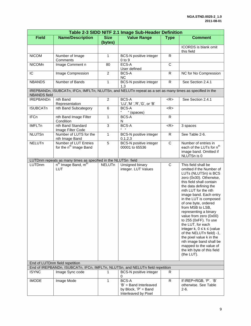
Table 2-3 SIDD NITF 2.1 Image Sub-Header Definition Field Name/Description Size
(bytes) Value Range Type Comment
ICORDS is blank omit this field
NICOM Number of Image Comments
1 BCS-N positive integer 0 to 9
R
NICOMn Image Comment n 80 ECS-A User defined
C
IC Image Compression 2 BCS-A NC
R NC for No Compression
NBANDS Number of Bands 1 BCS-N positive integer 1,3
R See Section 2.4.1
IREPBANDn, ISUBCATn, IFCn, IMFLTn, NLUTSn, and NELUTn repeat as a set as many times as specified in the NBANDS field
IREPBANDn nth Band Representation
2 BCS-A „LU‟,‟M „,‟R‟,‟G‟, or „B‟
<R> See Section 2.4.1
ISUBCATn nth Band Subcategory 6 BCS-A “ “ (spaces)
<R>
IFCn nth Band Image Filter Condition
1 BCS-A N
R
IMFLTn nth Band Standard Image Filter Code
3 BCS-A “ “
<R> 3 spaces
NLUTSn Number of LUTS for the nth Image Band
1 BCS-N positive integer 0,1,2,3
R See Table 2-6.
NELUTn Number of LUT Entries for the n
th Image Band
5 BCS-N positive integer 00001 to 65536
C Number of entries in each of the LUTs for n
th
image band. Omitted if NLUTSn is 0
LUTDnm repeats as many times as specified in the NLUTSn field
LUTDnm nth
Image Band, mth
LUT NELUTn Unsigned binary
integer. LUT Values C This field shall be
omitted if the Number of LUTs (NLUTSn) is BCS zero (0x30). Otherwise, this field shall contain the data defining the mth LUT for the nth image band. Each entry in the LUT is composed of one byte, ordered from MSB to LSB, representing a binary value from zero (0x00) to 255 (0xFF). To use the LUT, for each integer k, 0 ≤ k ≤ (value of the NELUTn field) -1, the pixel value k in the nth image band shall be mapped to the value of the kth byte of this field (the LUT).
End of LUTDnm field repetition
End of IREPBANDn, ISUBCATn, IFCn, IMFLTn, NLUTSn, and NELUTn field repetition
ISYNC Image Sync code 1 BCS-N positive integer 0
R
IMODE Image Mode 1 BCS-A „B‟ = Band Interleaved by Block, ‟P‟ = Band Interleaved by Pixel
R If IREP=RGB, „P‟. „B‟ otherwise. See Table 2-6.

NGA.STND.0025-2_1.0 2011-08-01
10
Table 2-3 SIDD NITF 2.1 Image Sub-Header Definition Field Name/Description Size
(bytes) Value Range Type Comment
NBPR Number of Blocks Per Row
4 BCS-N positive integer 0001
R
NBPC Number of Blocks Per Column
4 BCS-N positive integer 0001
R
NPPBH Number of Pixels Per Block Horizontal
4 BCS-N positive integer 0001-8192 or 0000
R If number of pixels in horizontal directional is more than 8192 populate with 0000 otherwise populate with zero padded version of number of columns
NPPBV Number of Pixels Per Block Vertical
4 BCS-N positive integer 0001-8192 or 0000
R If number of pixels in vertical directional is more than 8192 populate with 0000 otherwise populate with zero padded version of number of rows
NBPP Number of Bits Per Pixel Per Band
2 BCS-N positive integer 08 or 16
R See Table 2-6.
IDLVL Image Display Level. This field shall contain a valid value that indicates the display level of the image relative to other displayed file components in a composite display.
3 BCS-N positive integer. 001 to 999
R See Segmentation Rules – Section 2.4.2
IALVL Attachment Level 3 BCS-N positive integer R See Segmentation Rules – Section 2.4.2
ILOC Image Location. The image location is the location of the first pixel of the first line of the image. This field shall contain the image location offset from the ILOC or SLOC value of the segment to which the image is attached or from the origin of the CCS when the image is unattached (IALVL contains 000).
10 BCS-N
RRRRRCCCCC For positive row and column values RRRRR and CCCCC are both in the range 00000 to 99999. For negative row and column values RRRRR and CCCCC are both in the range -0001 to -9999
R See Segmentation Rules – Section 2.4.2
IMAG Image Magnification 4 BCS-A
R Default is 1.0
UDIDL User Defined Image Data Length
5 BCS-N positive integer 00000
R No TREs allowed
IXSHDL Image Extended Sub-Header Data Length
5 BCS-N positive integer 00000
R No TREs allowed
Type – R = Required, C = Conditional, <> surrounding the type = BCS SPACES ALLOWED FOR ENTIRE FIELD
NGA.STND.0025-2_1.0 2011-08-01
11
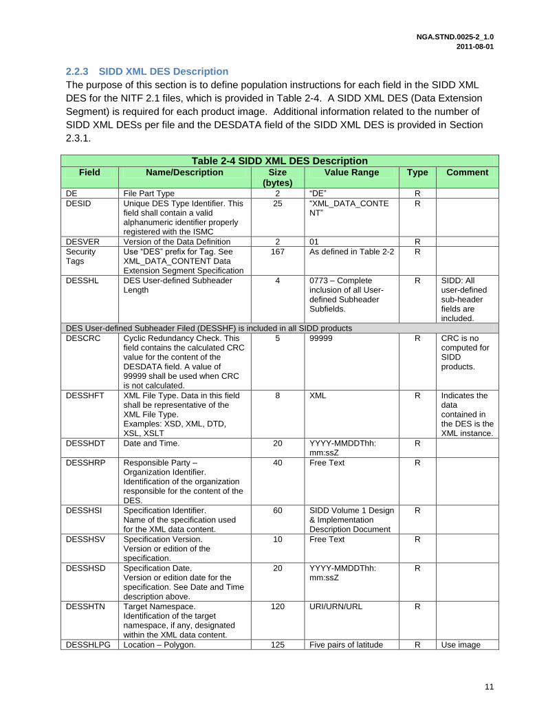
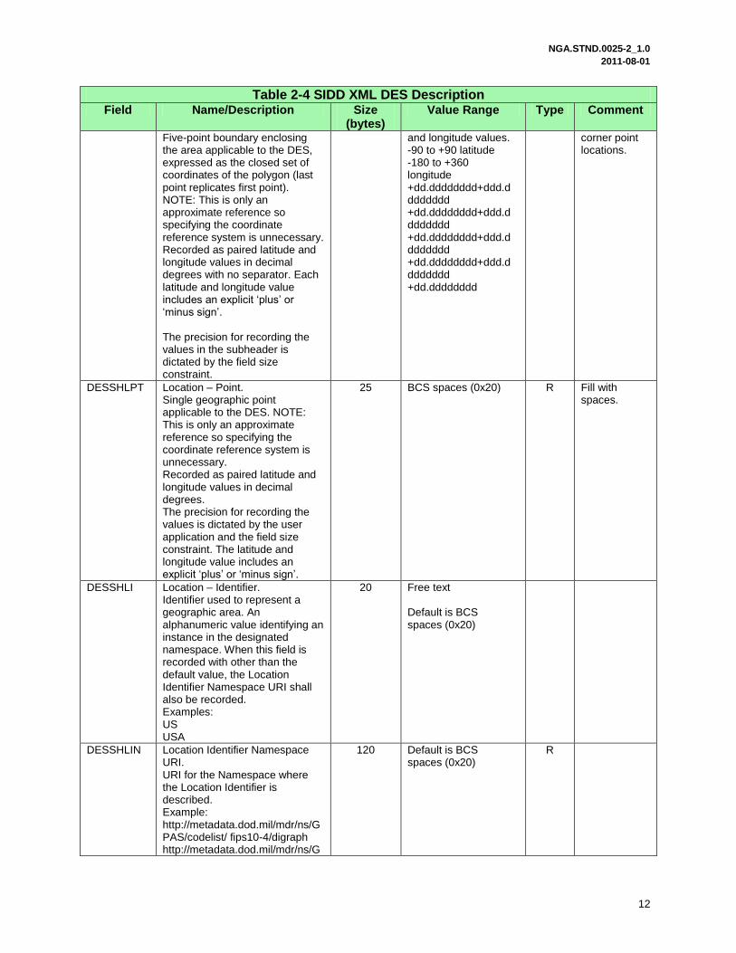
2.2.3 SIDD XML DES Description
The purpose of this section is to define population instructions for each field in the SIDD XML
DES for the NITF 2.1 files, which is provided in Table 2-4. A SIDD XML DES (Data Extension
Segment) is required for each product image. Additional information related to the number of
SIDD XML DESs per file and the DESDATA field of the SIDD XML DES is provided in Section
2.3.1.
Table 2-4 SIDD XML DES Description Field Name/Description Size
(bytes) Value Range Type Comment
DE File Part Type 2 “DE” R
DESID Unique DES Type Identifier. This field shall contain a valid alphanumeric identifier properly registered with the ISMC
25 “XML_DATA_CONTENT”
R
DESVER Version of the Data Definition 2 01 R
Security Tags
Use “DES” prefix for Tag. See XML_DATA_CONTENT Data Extension Segment Specification
167 As defined in Table 2-2 R
DESSHL DES User-defined Subheader Length
4 0773 – Complete inclusion of all User-defined Subheader Subfields.
R SIDD: All user-defined sub-header fields are included.
DES User-defined Subheader Filed (DESSHF) is included in all SIDD products
DESCRC Cyclic Redundancy Check. This field contains the calculated CRC value for the content of the DESDATA field. A value of 99999 shall be used when CRC is not calculated.
5 99999 R CRC is no computed for SIDD products.
DESSHFT XML File Type. Data in this field shall be representative of the XML File Type. Examples: XSD, XML, DTD, XSL, XSLT
8 XML R Indicates the data contained in the DES is the XML instance.
DESSHDT Date and Time. 20 YYYY-MMDDThh: mm:ssZ
R
DESSHRP Responsible Party – Organization Identifier. Identification of the organization responsible for the content of the DES.
40 Free Text R
DESSHSI Specification Identifier. Name of the specification used for the XML data content.
60 SIDD Volume 1 Design & Implementation Description Document
R
DESSHSV Specification Version. Version or edition of the specification.
10 Free Text R
DESSHSD Specification Date. Version or edition date for the specification. See Date and Time description above.
20 YYYY-MMDDThh: mm:ssZ
R
DESSHTN Target Namespace. Identification of the target namespace, if any, designated within the XML data content.
120 URI/URN/URL R
DESSHLPG Location – Polygon. 125 Five pairs of latitude R Use image
NGA.STND.0025-2_1.0 2011-08-01
12
Table 2-4 SIDD XML DES Description Field Name/Description Size
(bytes) Value Range Type Comment
Five-point boundary enclosing the area applicable to the DES, expressed as the closed set of coordinates of the polygon (last point replicates first point). NOTE: This is only an approximate reference so specifying the coordinate reference system is unnecessary. Recorded as paired latitude and longitude values in decimal degrees with no separator. Each latitude and longitude value includes an explicit ‘plus’ or ‘minus sign’. The precision for recording the values in the subheader is dictated by the field size constraint.
and longitude values. -90 to +90 latitude -180 to +360 longitude +dd.dddddddd+ddd.d ddddddd +dd.dddddddd+ddd.d ddddddd +dd.dddddddd+ddd.d ddddddd +dd.dddddddd+ddd.d ddddddd +dd.dddddddd
corner point locations.
DESSHLPT Location – Point. Single geographic point applicable to the DES. NOTE: This is only an approximate reference so specifying the coordinate reference system is unnecessary. Recorded as paired latitude and longitude values in decimal degrees. The precision for recording the values is dictated by the user application and the field size constraint. The latitude and longitude value includes an explicit ‘plus’ or ‘minus sign’.
25 BCS spaces (0x20) R Fill with spaces.
DESSHLI Location – Identifier. Identifier used to represent a geographic area. An alphanumeric value identifying an instance in the designated namespace. When this field is recorded with other than the default value, the Location Identifier Namespace URI shall also be recorded. Examples: US USA
20 Free text Default is BCS spaces (0x20)
DESSHLIN Location Identifier Namespace URI. URI for the Namespace where the Location Identifier is described. Example: http://metadata.dod.mil/mdr/ns/GPAS/codelist/ fips10-4/digraph http://metadata.dod.mil/mdr/ns/G
120 Default is BCS spaces (0x20)
R
NGA.STND.0025-2_1.0 2011-08-01
13
Table 2-4 SIDD XML DES Description Field Name/Description Size
(bytes) Value Range Type Comment
PAS/codelist/ iso3166-1/trigraph
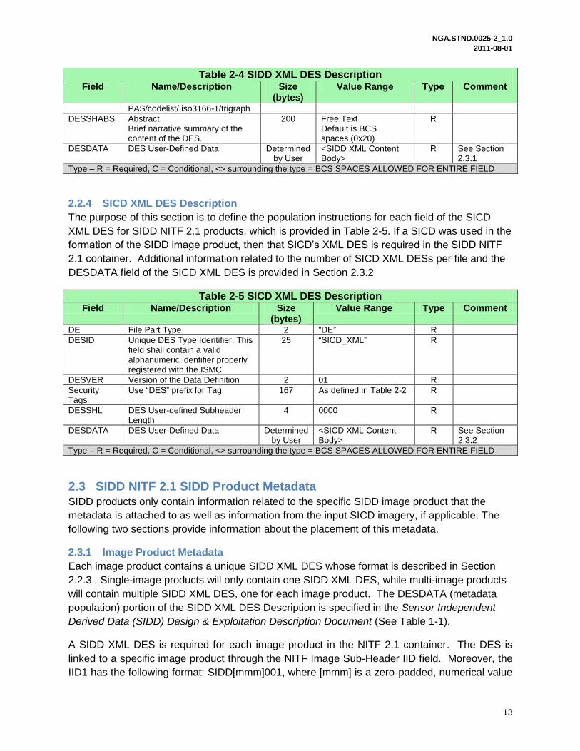
DESSHABS Abstract. Brief narrative summary of the content of the DES.
200 Free Text Default is BCS spaces (0x20)
R
DESDATA DES User-Defined Data
Determined by User
<SIDD XML Content Body>
R See Section 2.3.1
Type – R = Required, C = Conditional, <> surrounding the type = BCS SPACES ALLOWED FOR ENTIRE FIELD
2.2.4 SICD XML DES Description
The purpose of this section is to define the population instructions for each field of the SICD
XML DES for SIDD NITF 2.1 products, which is provided in Table 2-5. If a SICD was used in the
formation of the SIDD image product, then that SICD‟s XML DES is required in the SIDD NITF
2.1 container. Additional information related to the number of SICD XML DESs per file and the
DESDATA field of the SICD XML DES is provided in Section 2.3.2
Table 2-5 SICD XML DES Description Field Name/Description Size
(bytes) Value Range Type Comment
DE File Part Type 2 “DE” R
DESID Unique DES Type Identifier. This field shall contain a valid alphanumeric identifier properly registered with the ISMC
25 “SICD_XML” R
DESVER Version of the Data Definition 2 01 R
Security Tags
Use “DES” prefix for Tag 167 As defined in Table 2-2 R
DESSHL DES User-defined Subheader Length
4 0000 R
DESDATA DES User-Defined Data
Determined by User
<SICD XML Content Body>
R See Section 2.3.2
Type – R = Required, C = Conditional, <> surrounding the type = BCS SPACES ALLOWED FOR ENTIRE FIELD
2.3 SIDD NITF 2.1 SIDD Product Metadata
SIDD products only contain information related to the specific SIDD image product that the
metadata is attached to as well as information from the input SICD imagery, if applicable. The
following two sections provide information about the placement of this metadata.
2.3.1 Image Product Metadata
Each image product contains a unique SIDD XML DES whose format is described in Section
2.2.3. Single-image products will only contain one SIDD XML DES, while multi-image products
will contain multiple SIDD XML DES, one for each image product. The DESDATA (metadata
population) portion of the SIDD XML DES Description is specified in the Sensor Independent
Derived Data (SIDD) Design & Exploitation Description Document (See Table 1-1).
A SIDD XML DES is required for each image product in the NITF 2.1 container. The DES is
linked to a specific image product through the NITF Image Sub-Header IID field. Moreover, the
IID1 has the following format: SIDD[mmm]001, where [mmm] is a zero-padded, numerical value
NGA.STND.0025-2_1.0 2011-08-01
14
indicating the DES number. Furthermore, the DES number is determined by the order in which
the associated image product is located in the NITF file. For example, the seventh SIDD image
in the container is associated with the seventh DES; therefore, the IID1 field in the NITF sub-
header is populated with the IID1 = SIDD007001. The last three digits in the IID1 field are
utilized for segmentation as described in Section 2.4.2.
2.3.2 Input Image Metadata
Where possible, the SICD XML DES instances should be provided as references for advanced,
downstream exploitation. Therefore, for each SICD input image used for SIDD product
formation, a corresponding, unaltered SICD DES may be provided in the SIDD container. If the
SIDD product was not generated from a SICD, then a SICD XML DES is not required to be
present. While the SICD XML DESs should directly follow the SIDD XML DESs (with no empty
DESs allowed), the general ordering of the SICD DESs is unspecified (but could be specified by
an implementation profile).
Section 2.2.4 details the file format of the SICD DES. The DESDATA portion of the SICD XML
DES Description is provided in the Sensor Independent Complex Data (SICD) Design &
Exploitation Description Document (See Table 1-1).
2.4 SIDD Product Image Pixel Data
The purpose of this section is to specify the supported pixel types for SIDD NITF 2.1 products,
the segmentation procedure for large image products, the JPEG 2000 compression methods,
and information regarding legend creation.
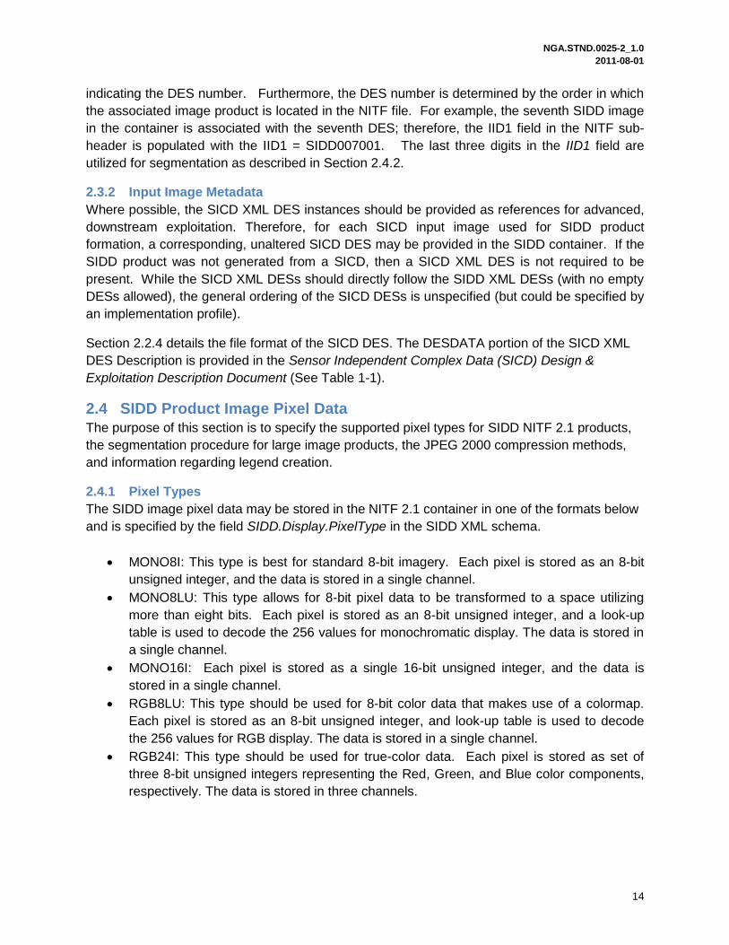
2.4.1 Pixel Types
The SIDD image pixel data may be stored in the NITF 2.1 container in one of the formats below
and is specified by the field SIDD.Display.PixelType in the SIDD XML schema.
MONO8I: This type is best for standard 8-bit imagery. Each pixel is stored as an 8-bit
unsigned integer, and the data is stored in a single channel.
MONO8LU: This type allows for 8-bit pixel data to be transformed to a space utilizing
more than eight bits. Each pixel is stored as an 8-bit unsigned integer, and a look-up
table is used to decode the 256 values for monochromatic display. The data is stored in
a single channel.
MONO16I: Each pixel is stored as a single 16-bit unsigned integer, and the data is
stored in a single channel.
RGB8LU: This type should be used for 8-bit color data that makes use of a colormap.
Each pixel is stored as an 8-bit unsigned integer, and look-up table is used to decode
the 256 values for RGB display. The data is stored in a single channel.
RGB24I: This type should be used for true-color data. Each pixel is stored as set of
three 8-bit unsigned integers representing the Red, Green, and Blue color components,
respectively. The data is stored in three channels.
NGA.STND.0025-2_1.0 2011-08-01
15
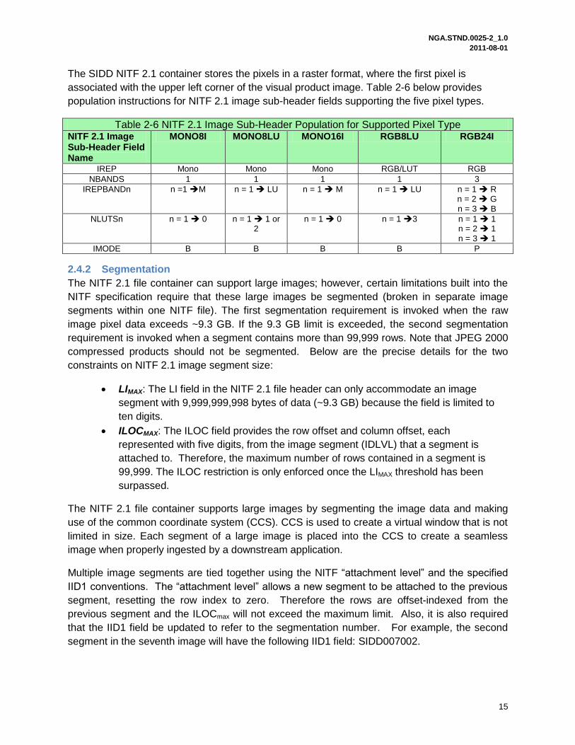
The SIDD NITF 2.1 container stores the pixels in a raster format, where the first pixel is
associated with the upper left corner of the visual product image. Table 2-6 below provides
population instructions for NITF 2.1 image sub-header fields supporting the five pixel types.
Table 2-6 NITF 2.1 Image Sub-Header Population for Supported Pixel Type NITF 2.1 Image Sub-Header Field Name
MONO8I MONO8LU MONO16I RGB8LU RGB24I
IREP Mono Mono Mono RGB/LUT RGB
NBANDS 1 1 1 1 3
IREPBANDn n =1 M n = 1 LU n = 1 M n = 1 LU n = 1 R n = 2 G n = 3 B
NLUTSn n = 1 0 n = 1 1 or 2
n = 1 0 n = 1 3 n = 1 1 n = 2 1 n = 3 1
IMODE B B B B P
2.4.2 Segmentation
The NITF 2.1 file container can support large images; however, certain limitations built into the
NITF specification require that these large images be segmented (broken in separate image
segments within one NITF file). The first segmentation requirement is invoked when the raw
image pixel data exceeds ~9.3 GB. If the 9.3 GB limit is exceeded, the second segmentation
requirement is invoked when a segment contains more than 99,999 rows. Note that JPEG 2000
compressed products should not be segmented. Below are the precise details for the two
constraints on NITF 2.1 image segment size:
LIMAX: The LI field in the NITF 2.1 file header can only accommodate an image
segment with 9,999,999,998 bytes of data (~9.3 GB) because the field is limited to
ten digits.
ILOCMAX: The ILOC field provides the row offset and column offset, each
represented with five digits, from the image segment (IDLVL) that a segment is
attached to. Therefore, the maximum number of rows contained in a segment is
99,999. The ILOC restriction is only enforced once the LIMAX threshold has been
surpassed.
The NITF 2.1 file container supports large images by segmenting the image data and making
use of the common coordinate system (CCS). CCS is used to create a virtual window that is not
limited in size. Each segment of a large image is placed into the CCS to create a seamless
image when properly ingested by a downstream application.
Multiple image segments are tied together using the NITF “attachment level” and the specified
IID1 conventions. The “attachment level” allows a new segment to be attached to the previous
segment, resetting the row index to zero. Therefore the rows are offset-indexed from the
previous segment and the ILOCmax will not exceed the maximum limit. Also, it is also required
that the IID1 field be updated to refer to the segmentation number. For example, the second
segment in the seventh image will have the following IID1 field: SIDD007002.

NGA.STND.0025-2_1.0 2011-08-01
16
Proper CCS usage requires that the following information in the NITF 2.1 file container
metadata be populated correctly:
NITF 2.1 Image Sub-Header o IDLVL o IALVL o ILOC o IID1
NITF 2.1 File Header o NUMI o LI(z)
The segmentation algorithm and population instructions for these fields are provided in the following sections.
2.4.2.1 Segmentation Algorithm
This section documents the SIDD segmentation algorithm for NITF 2.1 products.
The following pseudo-code shows how a SIDD product with M product images is segmented
and how the associated NITF container fields are populated. Variables that contain FHDR_ are
related to the NITF 2.1 file header and fields with IMHDR(z)_ are related to the zth NITF 2.1
image sub-header. The rows and columns of the Mth SIDD product images are defined as
NumCols(m) and NumRows(m). Note that the segmentation algorithm divides the image on
row boundaries such that the column offset is always zero.
Constants:
LIMAX = 9,999,999,998
ILOCMAX = 99,999
Number of Image Segments & Image Segment Size Parameters
z = 0; (Used to increment the image segments in the NITF 2.1 file
container.)
FHDR_NUMI = 0
For(k = 1,…,M) [Loop over product images]
BytesPerPixel = IMHDR(z)_NBANDS
BytesPerRow = BytesPerPixel*NumRows(k)
NumRowsLimit(k) = min(floor(LImax/BytesPerRow), ILOCMAX)
ProductSize = BytesPerPixel*NumRows(k)*NumCols(k)
If(ProductSize ≤ LIMAX) then,
z =z+1
FHDR_NUMI = FHDR_NUMI+1
FHDR_LI(z) = ProductSize
IMHDR(z)_IDLVL = z
IMHDR(z)_IALVL = 0
NGA.STND.0025-2_1.0 2011-08-01
17
IMHDR(z)_ILOC = 0000000000
IMHDR(z)_IID1 = “SIDD[mmm]001” where mmm is zero padded m
IMHDR(z)_NROWS = NumRowsLimit(k)
IMHDR(Z)_NCOLS = NumCols(k)
Else
NumSegPerImage(k) = NumRows(k)/NumRowsLimit(k)
z = z+1
FHDR_NUMI = FHDR_NUMI + NumSegPerImage(k)
FHDR_LI(z)= BytesPerPixel*NumRowsLimit(k)*NumCols(k)
IMHDR(z)_IDLVL = z
IMHDR(z)_IALVL = 0
IMHDR(z)_ILOC = 0000000000
IMHDR(z)_IID1 = “SIDD[mmm]001” where mmm is zero padded m
IMHDR(Z)_NCOLS = NumCols(k)
For(n=2,…,NumSegPerImage(k)-1)
z=z+1
FHDR_LI(z)= BytesPerPixel*NumRowsLimit(k)*NumCols(k)
IMHDR(z)_IDLVL=z
IMHDR(z)_IALVL=z-1
IMHDR(z)_ILOC = [RRRRR00000] RRRRR= zero padded
NumRowsLimit(k)
IMHDR(z)_IID1 = “SIDD[mmm][nnn]” (zero padded versions
of numbers)
IMHDR(z)_NROWS = NumRowsLimit(k)
IMHDR(Z)_NCOLS = NumCols(k)
End
z=z+1
lastSegRows=NumRows(k)-(NumSegPerImage(k)-
1)*NumRowsLimit(k)
FHDR_LI(z)=BytesPerPixel*lastSegRows*NumCols(k)
IMHDR(z)_IDLVL = z
IMHDR(z)_IALVL = z-1
IMHDR(z)_ILOC = [RRRRR00000] RRRRR=zero padded lastSegRows
IMHDR(z)_IID1 = “SIDD[kkk][nnn]” (zero padded versions of
numbers)
IMHDR(z)_NROWS = lastSegRows
IMHDR(Z)_NCOLS = NumCols(k)
End
End
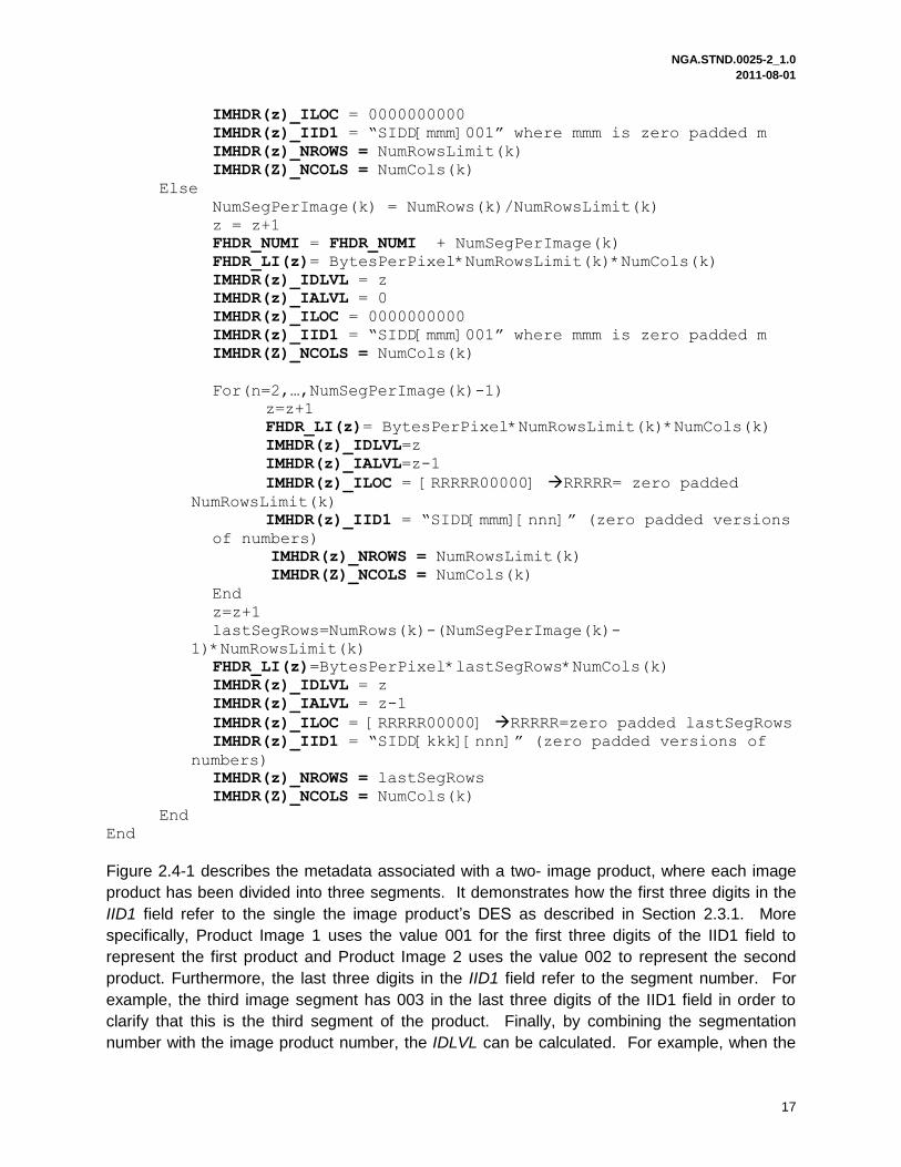
Figure 2.4-1 describes the metadata associated with a two- image product, where each image
product has been divided into three segments. It demonstrates how the first three digits in the
IID1 field refer to the single the image product‟s DES as described in Section 2.3.1. More
specifically, Product Image 1 uses the value 001 for the first three digits of the IID1 field to
represent the first product and Product Image 2 uses the value 002 to represent the second
product. Furthermore, the last three digits in the IID1 field refer to the segment number. For
example, the third image segment has 003 in the last three digits of the IID1 field in order to
clarify that this is the third segment of the product. Finally, by combining the segmentation
number with the image product number, the IDLVL can be calculated. For example, when the
NGA.STND.0025-2_1.0 2011-08-01
18
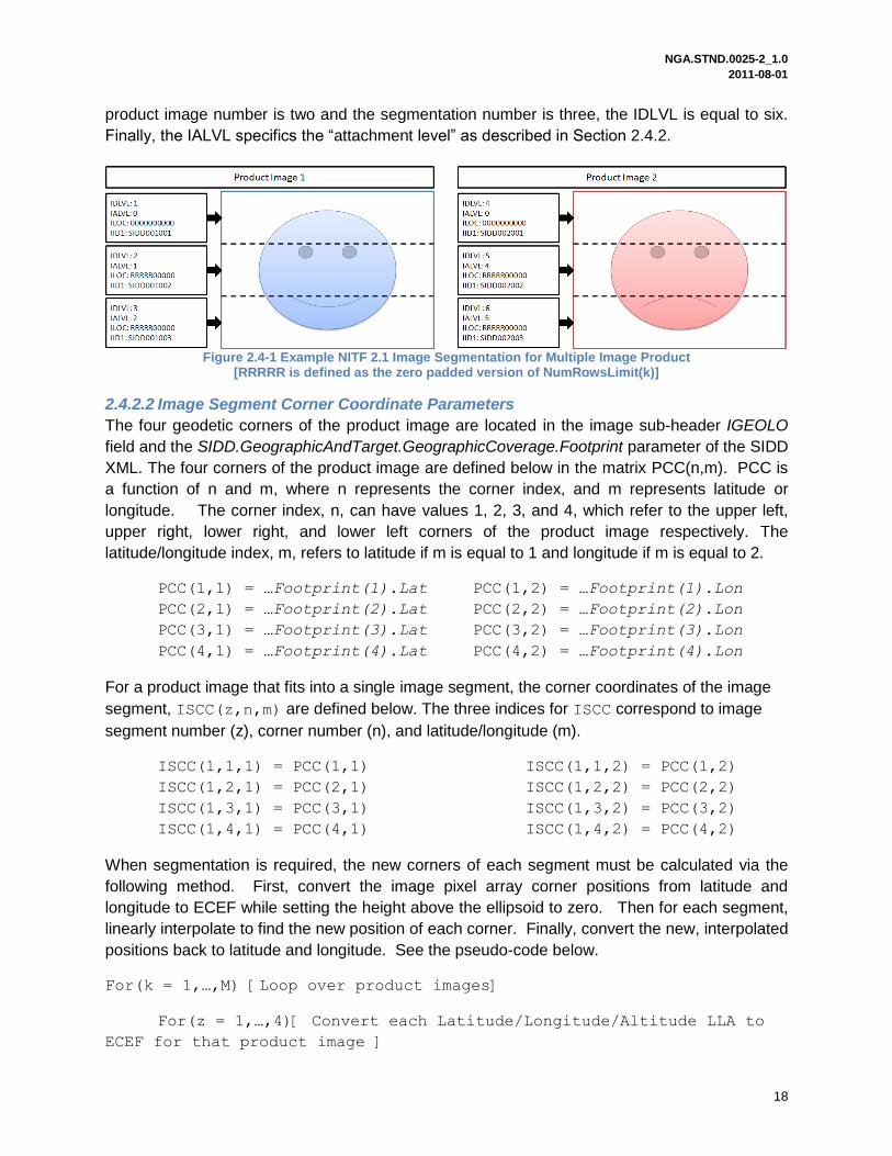
product image number is two and the segmentation number is three, the IDLVL is equal to six.
Finally, the IALVL specifics the “attachment level” as described in Section 2.4.2.
Figure 2.4-1 Example NITF 2.1 Image Segmentation for Multiple Image Product
[RRRRR is defined as the zero padded version of NumRowsLimit(k)]
2.4.2.2 Image Segment Corner Coordinate Parameters
The four geodetic corners of the product image are located in the image sub-header IGEOLO
field and the SIDD.GeographicAndTarget.GeographicCoverage.Footprint parameter of the SIDD
XML. The four corners of the product image are defined below in the matrix PCC(n,m). PCC is
a function of n and m, where n represents the corner index, and m represents latitude or
longitude. The corner index, n, can have values 1, 2, 3, and 4, which refer to the upper left,
upper right, lower right, and lower left corners of the product image respectively. The
latitude/longitude index, m, refers to latitude if m is equal to 1 and longitude if m is equal to 2.
PCC(1,1) = …Footprint(1).Lat PCC(1,2) = …Footprint(1).Lon
PCC(2,1) = …Footprint(2).Lat PCC(2,2) = …Footprint(2).Lon
PCC(3,1) = …Footprint(3).Lat PCC(3,2) = …Footprint(3).Lon
PCC(4,1) = …Footprint(4).Lat PCC(4,2) = …Footprint(4).Lon
For a product image that fits into a single image segment, the corner coordinates of the image
segment, ISCC(z,n,m) are defined below. The three indices for ISCC correspond to image
segment number (z), corner number (n), and latitude/longitude (m).
ISCC(1,1,1) = PCC(1,1) ISCC(1,1,2) = PCC(1,2)
ISCC(1,2,1) = PCC(2,1) ISCC(1,2,2) = PCC(2,2)
ISCC(1,3,1) = PCC(3,1) ISCC(1,3,2) = PCC(3,2)
ISCC(1,4,1) = PCC(4,1) ISCC(1,4,2) = PCC(4,2)
When segmentation is required, the new corners of each segment must be calculated via the
following method. First, convert the image pixel array corner positions from latitude and
longitude to ECEF while setting the height above the ellipsoid to zero. Then for each segment,
linearly interpolate to find the new position of each corner. Finally, convert the new, interpolated
positions back to latitude and longitude. See the pseudo-code below.
For(k = 1,…,M) [Loop over product images]
For(z = 1,…,4)[ Convert each Latitude/Longitude/Altitude LLA to
ECEF for that product image ]

NGA.STND.0025-2_1.0 2011-08-01
19
Convert PCC (in LLA) to PCC_ECEF(in ECEF)
End
For(z = 1,…,NumSegPerImage(k) (defined above))
wgt1 = ((z-1)*NumRowsLimit(k))/NumRows(k)
wgt2 = 1-wgt1
wgt3 = ((z-1)*NumRowsLimit(k)+IMHDR(z)_NROWS)/NumRows(k)
wgt4 = 1-wgt3
ISCC_ECEF(z,1) = wgt2*PCC_ECEF(1)+wgt1*PCC_ECEF(4)
ISCC_ECEF(z,2) = wgt2*PCC_ECEF(2)+wgt1*PCC_ECEF(3)
ISCC_ECEF(z,3) = wgt4*PCC_ECEF(2)+wgt3*PCC_ECEF(3)
ISCC_ECEF(z,4) = wgt4*PCC_ECEF(1)+wgt3*PCC_ECEF(4)
For(n = 1,…,4)
Convert PCC_ECEF(z,n) (in ECEF) to ISCC(z,n) (in LLA)
End
IMHDR(z)_IGEOLO = [ISCC(z,1,1) ISCC(z,1,2) ISCC(z,2,1)
ISCC(z,2,2) ISCC(z,3,1) ISCC(z,3,2) ISCC(z,4,1)
ISCC(z,4,2)]
End
End
2.4.3 Legends
Legend products may also be stored as part of the SIDD NITF 2.1 file container. Generally
speaking, a legend is treated as an image with the following alterations. The ICAT field in the
image sub-header must be populated with LEG instead of SAR. Furthermore, in SIDD products
the legend is required to be located after the final SAR image data segment in a particular SIDD
product, regardless of segmentation. Thus, if a SIDD product image required segmentation into
N parts, then the legend(s) would start at N+1. Additionally, the legend cannot exceed the 9.3
GB image segment constraint. Table 2-7 contains header population instructions for legend
images. Legend segments are not associated with any SIDD XML DES.
Table 2-7 SIDD NITF 2.1 File Container Metadata Population Instructions for Legends File Header/Image Sub-Header
Field Instruction
Image Sub-Header ICAT Populate with “LEG”
Image Sub-Header IID1 “SIDDmmmnnn” where mmm is the SIDD product image number associated with the legend and nnn is the number of image segments that the SIDD product image required+ 1 (or more for multiple legends). The first legend segment (ICAT = LEG) must have a larger nnn value than the highest valued image segment (ICAT = SAR) for that SIDD product image.

NGA.STND.0025-2_1.0 2011-08-01
20
Table 2-7 SIDD NITF 2.1 File Container Metadata Population Instructions for Legends File Header/Image Sub-Header
Field Instruction
Image Sub-Header IDLVL The IDLVL of a legend segment corresponding to a SIDD product image must be higher than the highest SAR segment. In a multiple product image SIDD, the IDLVL value for a legend image related to the m
th product image must be
higher than the highest SAR segment for the mth
product image but less than the lowest SAR segment of the m+1 product image.
Image Sub-Header IALVL The legend must be attached to the image segment of the SIDD product image where it‟s display is desired. For example, if the legend is meant to be in the top right of the SIDD product image the attachment level should reference the IDLVL level of the first segment of the SIDD product image. If the desire is to place the legend in the lower right then the attachment level should be equal to the IDLVL level of the last segment of the SIDD product image.
Image Sub-Header ILOC The row and column offsets are specified in this field are relative to the upper left corner (0,0) of the image segment that the legend is being attached to. For example, if the desire is to place legend in the upper left this field would be (0,0)0000000000. Likewise if the desire is to place it near the lower right corner of the segment that it is being attached to then this field would be (NumRows-x,NumCols-y).
File Header NUMI The procedure outlined in section 2.4.2 should be followed but for each legend added NUMI should be incremented by 1.
File Header LIn The procedure outlined in section 2.4.2 for calculating an image segment size should be used for legend segments
2.4.4 JPEG 2000 Compression
The SIDD NITF 2.1 file container supports JPEG 2000 compression for storing image data. The
purpose of this section is to specify JPEG 2000 compression impacts on the NITF 2.1 image
sub-header metadata. The JPEG 2000 codestream definition for SIDD NITF 2.1 products is
detailed in Appendix B - JPEG 2000 Codestream Definition.
2.4.4.1 SIDD NITF 2.1 File Header for JPEG 2000 Compressed Images
The use of JPEG 2000 compression does not impact the population of the SIDD file header.
Population instructions for the SIDD NITF 2.1 file header are defined in Section 2.2.1.
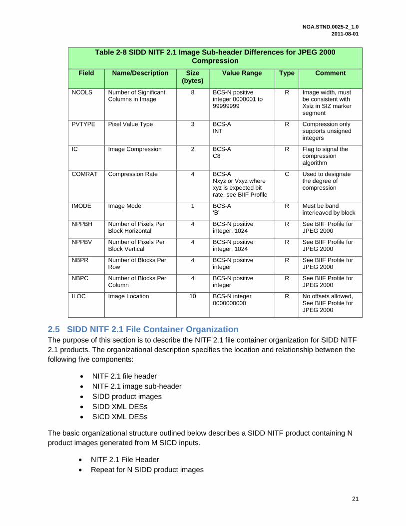
2.4.4.2 SIDD NITF 2.1 Image Sub-header for JPEG 2000 Compressed Images
This section defines population instructions for fields in the image sub-header that are impacted
by JPEG 2000 compression. Specific implementation details are provided in Table 2-8.
Furthermore, additional information regarding image sub-header population when using JPEG
2000 compression is available in Section 9.2.2 of the BIIF Profile for JPEG 2000. As a reminder,
segmentation is not allowed when JPEG 2000 compression is utilized.
Table 2-8 SIDD NITF 2.1 Image Sub-header Differences for JPEG 2000 Compression
Field Name/Description Size (bytes)
Value Range Type Comment
NROWS Number of Significant Rows in Image
8 BCS-N positive integer 0000001 to 99999999
R Image length, must be consistent with Ysiz in SIZ marker segment
NGA.STND.0025-2_1.0 2011-08-01
21
Table 2-8 SIDD NITF 2.1 Image Sub-header Differences for JPEG 2000 Compression
Field Name/Description Size (bytes)
Value Range Type Comment
NCOLS Number of Significant Columns in Image
8 BCS-N positive integer 0000001 to 99999999
R Image width, must be consistent with Xsiz in SIZ marker segment
PVTYPE Pixel Value Type 3 BCS-A INT
R Compression only supports unsigned integers
IC Image Compression 2 BCS-A C8
R Flag to signal the compression algorithm
COMRAT Compression Rate 4 BCS-A Nxyz or Vxyz where xyz is expected bit rate, see BIIF Profile
C Used to designate the degree of compression
IMODE Image Mode 1 BCS-A „B‟
R Must be band interleaved by block
NPPBH Number of Pixels Per Block Horizontal
4 BCS-N positive integer: 1024
R See BIIF Profile for JPEG 2000
NPPBV Number of Pixels Per Block Vertical
4 BCS-N positive integer: 1024
R See BIIF Profile for JPEG 2000
NBPR Number of Blocks Per Row
4 BCS-N positive integer
R See BIIF Profile for JPEG 2000
NBPC Number of Blocks Per Column
4 BCS-N positive integer
R See BIIF Profile for JPEG 2000
ILOC Image Location 10 BCS-N integer 0000000000
R No offsets allowed, See BIIF Profile for JPEG 2000
2.5 SIDD NITF 2.1 File Container Organization
The purpose of this section is to describe the NITF 2.1 file container organization for SIDD NITF
2.1 products. The organizational description specifies the location and relationship between the
following five components:
NITF 2.1 file header
NITF 2.1 image sub-header
SIDD product images
SIDD XML DESs
SICD XML DESs
The basic organizational structure outlined below describes a SIDD NITF product containing N
product images generated from M SICD inputs.
NITF 2.1 File Header
Repeat for N SIDD product images

NGA.STND.0025-2_1.0 2011-08-01
22
o NITF 2.1 Image Sub-Header
o SIDD Product Image (Raster format, starting at visual upper left corner of
image)
Repeat for N SIDD product images
o SIDD XML DES
Repeat for M SICD input images
o SICD XML DES (if available)
The next five sections provide examples of the organization of SIDD NITF 2.1 products for
clarification.
2.5.1 Single Input Image - Single Product Image
The simplest SIDD product is a single product image generated from a single input image,
which is shown in Figure 2.5-1. In this example, the SIDD NITF 2.1 file is organized in the
following order: NITF 2.1 File Header, NITF 2.1 Image Sub-header and image data for Product
Image 1, DES 1 – SIDD XML, and DES 2 – SICD XML. DES 1 SIDD XML is linked with the first
product image by setting the IID1 field in the Image Sub-Header to SIDD001001. The single
SICD XML DES from the input SICD image is contained in DES 2. Additional details on how
these components are organized are in Sections 2.2, 2.3, and 2.4.
Figure 2.5-1 - SIDD NITF 2.1 File Container Organization - Single Input Image/Single Product Image
2.5.1.1 Single Input Image – Single Product Image using JPEG 2000 Compression
SIDD NITF 2.1 products that use JPEG 2000 compression are organized in the same manner
as those without compression at the highest level. The main difference is that JPEG 2000
compression results in image data that contains the JPEG 2000 codestream instead of just the
raw raster image. The JPEG 2000 codestream is defined in further detail in Appendix B -
JPEG 2000 Codestream Definition.

NGA.STND.0025-2_1.0 2011-08-01
23
Figure 2.5-2 - SIDD NITF 2.1 w/JPEG 2000 Compression Single Input - Single Product Image Example
2.5.2 Multiple Input Images – Single Product Image
A SIDD NITF 2.1 product containing a single SIDD image product that is generated from
multiple SICD inputs is shown in Figure 2.5-3. This product is organized the same as the
product in Section 2.5.1 except there are two SICD DESs present. In this case, the SIDD
product is generated from two SICD inputs. The ordering of the SICD DESs is unspecified but
could be specified by an implementation profile. If JPEG 2000 compression is used, the NITF
2.1 Image Segment is modified in the same manner as described in Section 2.5.1.1.
Figure 2.5-3 - SIDD NITF 2.1 File Container Organization - Multiple Input Images/Single Product Image
2.5.3 Single Input Image – Multiple Product Images
A SIDD NITF 2.1 product containing multiple SIDD image products that are generated from a
single input SICD is shown in Figure 2.5-4. This product is organized the same as the product in
Section 2.5.1 except that a second product image and SIDD XML DES instance are present.
SIDD NITF 2.1
NITF 2.1 File Header
NITF 2.1 Image Segment – Product Image 1
DES 1 – SIDD XML (Product Image 1)
DES 2 – SICD XML (Input Image 1)
NITF 2.1 Image Sub-Header
JPEG 2000 Codestream

NGA.STND.0025-2_1.0 2011-08-01
24
The product images are linked to their associated SIDD XML via the IID1 field. The SICD XML
DES is now the 3rd DES in the file because two product images exist and their associated SIDD
XML DESs must precede the SICD XML DES. If JEPG 2000 compression is used, the NITF 2.1
Image Segments are modified in the same manner as described in Section 2.5.1.1.
Figure 2.5-4 - SIDD NITF 2.1 File Container Organization - Single Input Image/Multiple Product Images
2.5.4 Single Input Image – Single Product Image Requiring Segmentation
A single SIDD image product requiring segmentation that is generated from a single SICD input
is shown in Figure 2.5-4. This product is organized the same as the product in Section 2.5.1
except for that the product image requires segmentation due to NITF file container size
constraints.
The following details population instructions for a product that requires segmentation. The first
segment in each product image has the IALVL set to 0 to indicate that it is attached directly to
the CCS. The second segment is linked to the first by setting its IALVL value to the IDLVL value
found in the first segment. Furthermore, within the container, the second image product
segment directly follows the first segment. For this example, the IID1 field for the second
segment of Product Image 1 is set to SIDD001002 where the 001 indicates the product image,
and the 002 indicates the second segment. Thus, this product image is associated with DES 1
because the IID1 field is set to 001. Additional fields must be set to ensure that segmentation
works properly; the section on segmentation, section 2.4.2, specifies these details.
NGA.STND.0025-2_1.0 2011-08-01
25
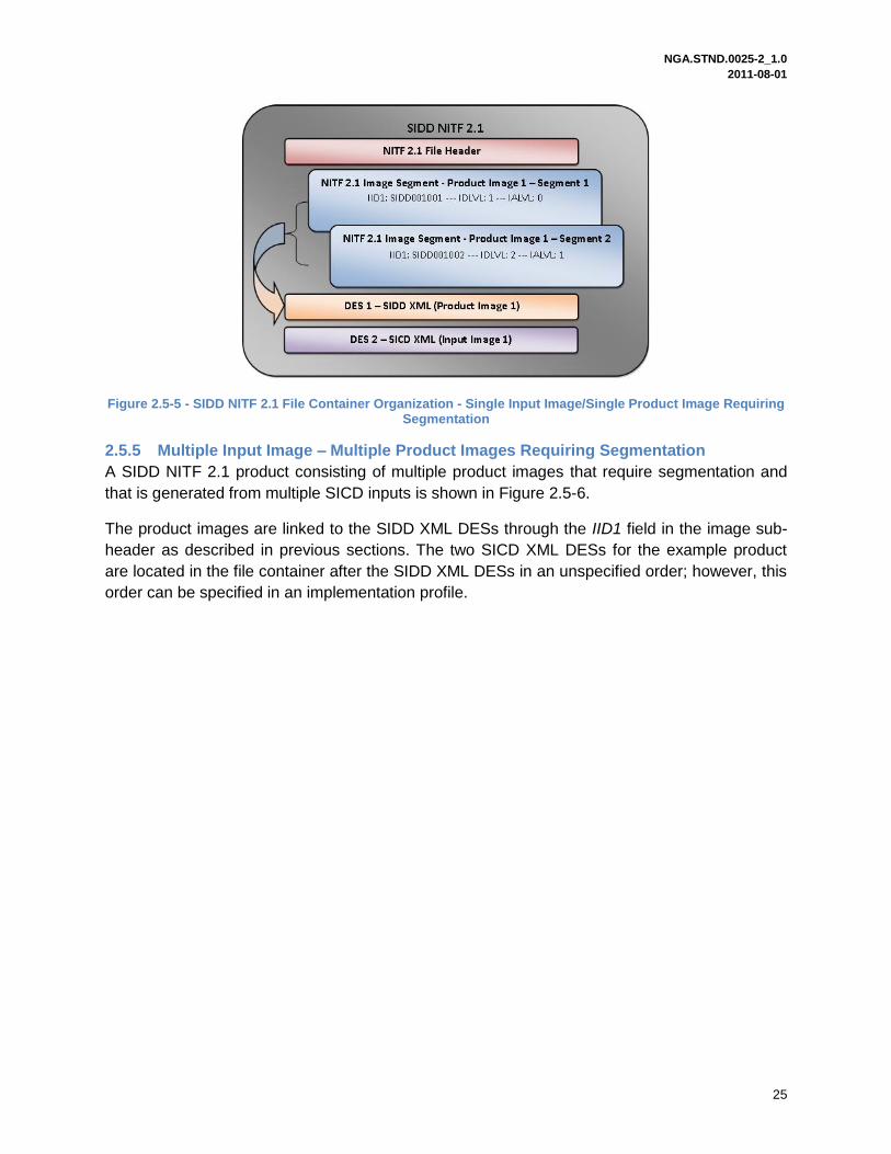
Figure 2.5-5 - SIDD NITF 2.1 File Container Organization - Single Input Image/Single Product Image Requiring Segmentation
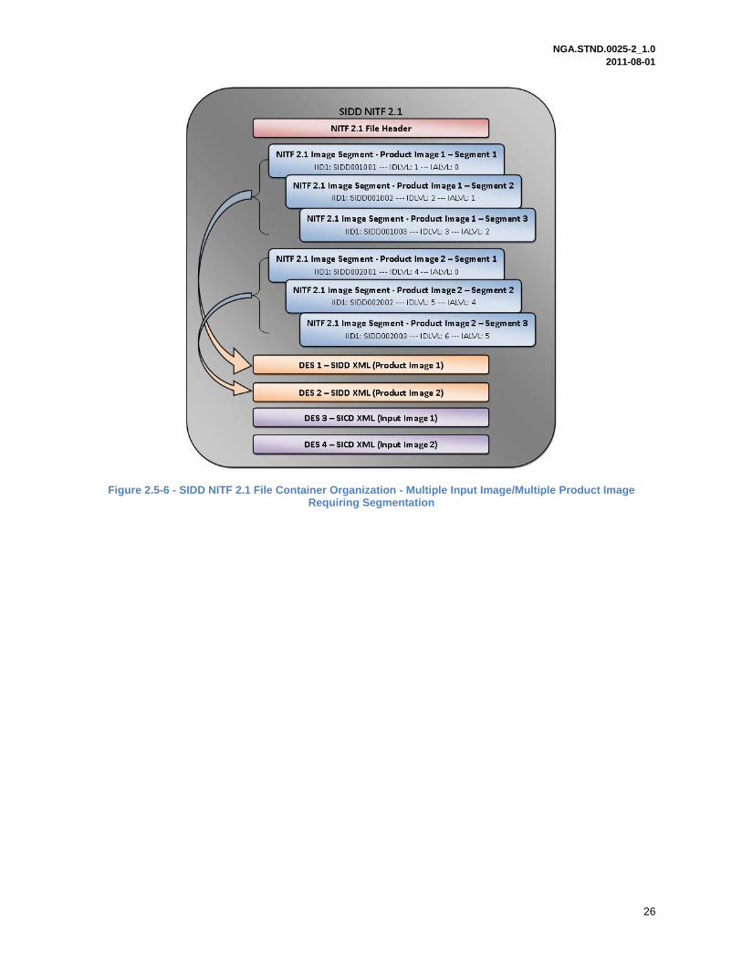
2.5.5 Multiple Input Image – Multiple Product Images Requiring Segmentation
A SIDD NITF 2.1 product consisting of multiple product images that require segmentation and
that is generated from multiple SICD inputs is shown in Figure 2.5-6.
The product images are linked to the SIDD XML DESs through the IID1 field in the image sub-
header as described in previous sections. The two SICD XML DESs for the example product
are located in the file container after the SIDD XML DESs in an unspecified order; however, this
order can be specified in an implementation profile.
NGA.STND.0025-2_1.0 2011-08-01
26
Figure 2.5-6 - SIDD NITF 2.1 File Container Organization - Multiple Input Image/Multiple Product Image Requiring Segmentation
NGA.STND.0025-2_1.0 2011-08-01
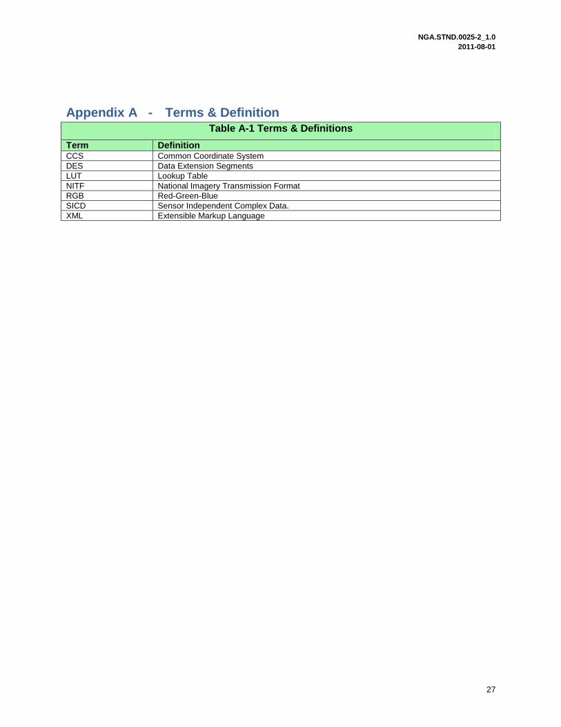
27
Appendix A - Terms & Definition Table A-1 Terms & Definitions
Term Definition CCS Common Coordinate System
DES Data Extension Segments
LUT Lookup Table
NITF National Imagery Transmission Format
RGB Red-Green-Blue
SICD Sensor Independent Complex Data.
XML Extensible Markup Language

NGA.STND.0025-2_1.0 2011-08-01
28
Appendix B - JPEG 2000 Codestream Definition
The SIDD NITF 2.1 format includes an option to apply JPEG 2000 compression to image data in
order to reduce file size. This option is primarily intended to provide a solution for very large
image segments with data sizes exceeding NITF maximum image segment size limits
(Approximately 9.3GB). JPEG 2000 compression is offered as an alternative choice to image
segment partitioning for very large image segments.
The JPEG 2000 standard is very complex, offering a vast number of options for compression
and resolution. The SIDD implementation will be limited to a specific set of parameters based on
the NITF/JPEG 2000 recommendation, BIIF Profile for JPEG 2000 Version 01.00
(BPJ2K01.00), see Table 1-2. The only options used in SIDD are numerically lossless or
visually lossless compression.
The use of JPEG 2000 compression places restrictions on some of the image segment sub-
header fields. These restrictions are found in both BPJ2K01.00 and MIL-STD-2500C. In some
cases the restrictions are actually recommendations in BPJ2K01.00 and these
recommendations will be followed. This section provides the following pieces of information:
JPEG 2000 Codestream Layout
JPEG 2000 Image Data
JPEG 2000 Marker Definitions
B.1 JPEG 2000 Codestream Layout
The JPEG 2000 codestream is composed of a sequence of marker segments. Each segment
starts with a 16-bit marker (code) followed by zero or more parameters. The marker segments
are organized into groups. The SIDD parameterization of the markers in the individual groups is
discussed below.
The image pixels are mapped onto a reference grid and divided into tiles. The tiles form a
rectangular array and are placed in the file in row order. The SIDD implementation places the
first tile (upper left corner) at (0,0) in the reference grid which coincides with the NITF CCS.
Tiles and NITF block sizes are both 1024x1204 and blocks and tiles coincide. This is a SIDD
specific usage of the more general case and also the BP2K01.00 recommendation.
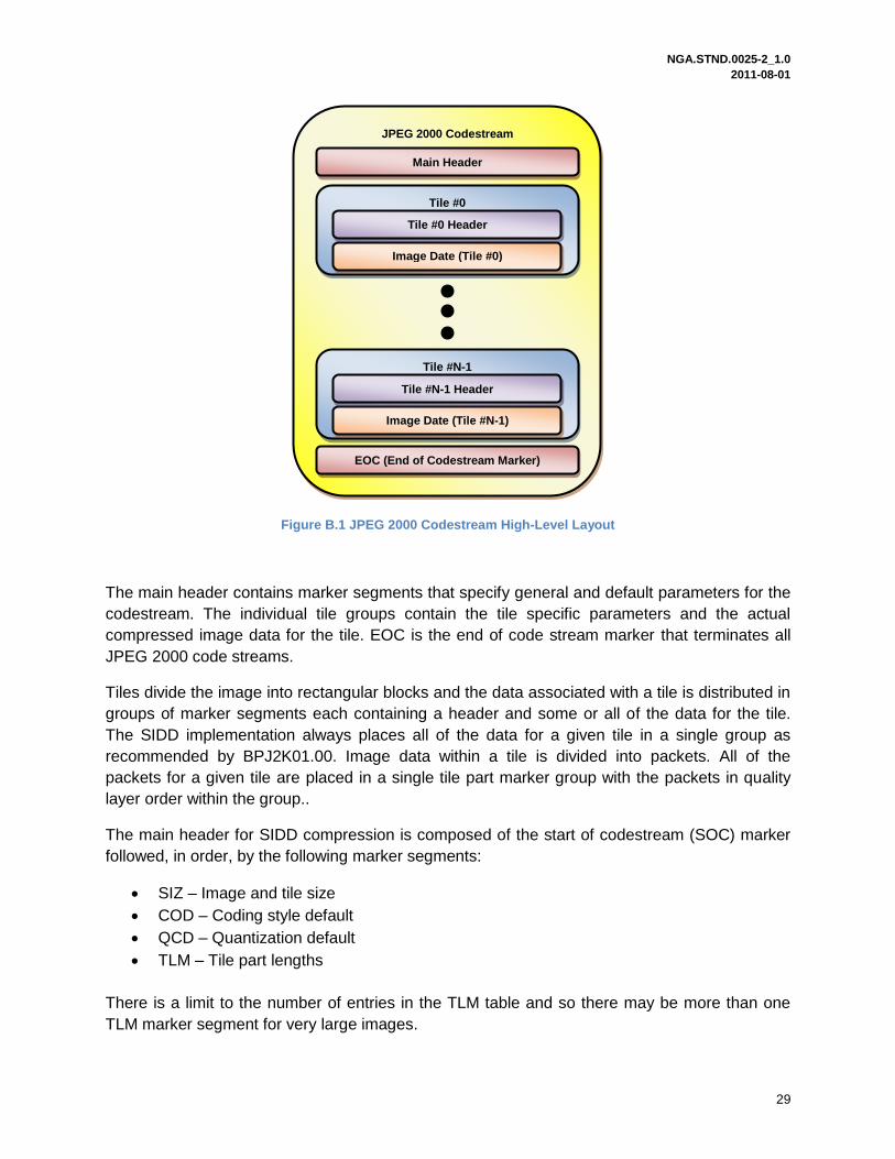
The high level layout of the JPEG 2000 codestream is shown in Figure B.1. The JPEG 2000
Main Header layout is expanded in Figure B.2. The JPEG 2000 Tile Header layout is expanded
in Figure B.3. The JPEG 2000 Main Header marker segments are defined in Section B.3.1.
NGA.STND.0025-2_1.0 2011-08-01
29
Figure B.1 JPEG 2000 Codestream High-Level Layout
The main header contains marker segments that specify general and default parameters for the
codestream. The individual tile groups contain the tile specific parameters and the actual
compressed image data for the tile. EOC is the end of code stream marker that terminates all
JPEG 2000 code streams.
Tiles divide the image into rectangular blocks and the data associated with a tile is distributed in
groups of marker segments each containing a header and some or all of the data for the tile.
The SIDD implementation always places all of the data for a given tile in a single group as
recommended by BPJ2K01.00. Image data within a tile is divided into packets. All of the
packets for a given tile are placed in a single tile part marker group with the packets in quality
layer order within the group..
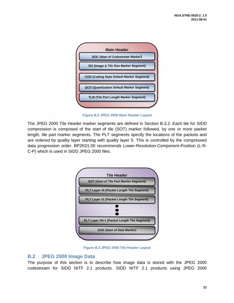
The main header for SIDD compression is composed of the start of codestream (SOC) marker
followed, in order, by the following marker segments:
SIZ – Image and tile size
COD – Coding style default
QCD – Quantization default
TLM – Tile part lengths
There is a limit to the number of entries in the TLM table and so there may be more than one
TLM marker segment for very large images.
JPEG 2000 Codestream
Main Header
Tile #0
Image Date (Tile #0)
Tile #0 Header
Tile #N-1
Image Date (Tile #N-1)
Tile #N-1 Header
EOC (End of Codestream Marker)
NGA.STND.0025-2_1.0 2011-08-01
30
Figure B.2 JPEG 2000 Main Header Layout
The JPEG 2000 Tile Header marker segments are defined in Section B.3.2. Each tile for SIDD
compression is composed of the start of tile (SOT) marker followed, by one or more packet
length, tile part marker segments. The PLT segments specify the locations of the packets and
are ordered by quality layer starting with quality layer 0. This is controlled by the compressed
data progression order. BP2K01.00 recommends Lower-Resolution-Component-Position (L-R-
C-P) which is used in SIDD JPEG 2000 files.
Figure B.3 JPEG 2000 Tile Header Layout
B.2 JPEG 2000 Image Data
The purpose of this section is to describe how image data is stored with the JPEG 2000
codestream for SIDD NITF 2.1 products. SIDD NITF 2.1 products using JPEG 2000
Tile Header
SOT (Start of Tile Part Marker Segment)
PLT Layer #0 (Packet Length Tile Segment)
PLT Layer #1 (Packet Length Tile Segment)
PLT Layer #N-1 (Packet Length Tile Segment)
SOD (Start of Data Marker)
Main Header
SOC (Start of Codestream Marker)
SIZ (Image & Tile Size Marker Segment)
COD (Coding Style Default Marker Segment)
QCD (Quantization Default Marker Segment)
TLM (Tile Part Length Marker Segment)
NGA.STND.0025-2_1.0 2011-08-01
31
compression can use either visually lossless or numerically lossless compression. The following
items will be covered in this section.
Visually lossless compression
Numerically lossless compression
Layer ordering
B.2.1 Visually Lossless Compression
SIDD NITF 2.1 products using JPEG 2000 compression can use visually lossless compression.
Visually lossless compression allows for greater compression ratios at the cost of quality. The
choice of visually lossless versus numerically lossless is dependent on a multitude factors which
include, but is not limited to, end-user requirements, data transfer requirements, and data
storage requirements. Guidance is provided in Appendix A of the BIIF profile for JPEG 2000 as
to when visually lossless compression or numerically lossless compression should be used.
B.2.2 Numerically Lossless Compression
SIDD NITF 2.1 products using JPEG 2000 compression can use numerically lossless
compression. Numerically lossless compression preserves all information at the cost of smaller
compression ratios. Because RGB/LUT and MONO/LUT pixel values are indexes, only
numerically lossless is allowed for this case. Further explanation of the compression can be
found in BIIF Profile for JPEG 2000 and references within that document.
B.2.3 Layer Ordering
The image bits in a JPEG 2000 codestream can be arranged in several different ways. SIDD
NITF 2.1 products using JPEG 2000 compression use the recommended methodology specified
in the BIIF Profile for JPEG 2000. The recommended method is the Layer-Resolution-
Component-Position ordering (L-R-C-P). This ordering means that the data is first organized by
increasing quality layer. Within a quality layer the data is arranged in increasing resolution.
Within a given resolution level the data is arranged in component order. The details are
provided in this section with further explanation can be found in section 8.2 of the BIIF Profile for
JPEG 2000.
B.3 JPEG 2000 Segment Marker Definitions
The purpose of this section is to provide the population instructions for the JPEG 2000 Marker
Segments required by SIDD NITF 2.1 products using JPEG 2000 compression.
B.3.1 JPEG 2000 Main Header
The purpose of this section is to define the population instructions for the JPEG 2000 main
header segments. The JPEG 2000 main header segments used by SIDD NITF 2.1 products are
the SOC, SIZ, COD, QCD, and TLM segments. Further details are provided in Sections 7 and
8.4 of the BIIF Profile for JPEG 2000.
B.3.1.1 Start of Codestream Marker (SOC)
The SOC marker is required to be the first item in the JPEG 2000 codestream and JPEG 2000
main header. The SOC marker is defined in the table below.

NGA.STND.0025-2_1.0 2011-08-01
32
Table B-1 Start of Codestream (SOC) Marker
Parameter Size (bytes) Value Comments
SOC 2 OxFF4F Start of codestream marker
B.3.1.2 Image & Tile Size Marker Segment (SIZ)
The SIZ marker is required as the second marker segment in the JPEG 2000 main header. The
SIZ marker segment is defined in the table below.
Table B-2 Image & Tile Size (SIZ) Marker Segment
Parameter Size (bytes) Value Comments
SIZ 2 0xFF51 Image and tile size marker
Lsiz 2 38+3*Csiz Length of this marker segment in bytes, not including the marker
Rsiz 2 0 No profile defined
Xsiz 4 Image width Number of columns (NCOLS in NITF 2.1 Image Sub-Header)
Ysiz 4 Image height Number of rows (NROWS in NITF 2.1 Image Sub-Header)
XOSiz 4 0 Image column coordinate of upper left corner in the reference grid and CCS
Y0Siz 4 0 Image row coordinate of upper left corner in the reference grid and CCS
XTsiz 4 1024 Tile width in reference grid and CCS
YTsiz 4 1024 Tile length in reference grid and CCS
XTOsiz 4 0 Horizontal offset from the origin of the reference grid to the left edge of the first tile
YTOsiz 4 0 Vertical offset from the origin of the reference grid to the top edge of the first tile
Csiz 2 1 or 3 Number of components in the image. NBANDs in the NITF 2.1 Image Sub-header.
Repeat below for each band (1 thru Csiz)
Ssiz(i) 1 7 or 15 Bit depth of data = value + 1 (MONO16I is 15, all other types are 7)
XRsiz(i) 1 Calculated (Default = 1)
Horizontal separation of a sample of the ith
component with respect to the reference grid
YRsiz 1 Calculated (Default = 1)
Vertical separation of a sample of the ith component
with respect to the reference grid
B.3.1.3 Coding Style Default Marker Segment (COD)
The coding style default marker (COD) provides default coding style parameters. The
parameters control compression details such as progression, number of layers, and wavelet
transform. The JPEG 2000 specification allows for COD markers in the tile header which are not
allowed in this specification. The COD marker segment is defined in the table below.
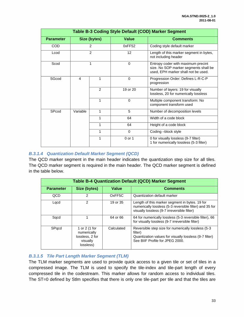
NGA.STND.0025-2_1.0 2011-08-01
33
Table B-3 Coding Style Default (COD) Marker Segment
Parameter Size (bytes) Value Comments
COD 2 0xFF52 Coding style default marker
Lcod 2 12 Length of this marker segment in bytes, not including header
Scod 1 0 Entropy coder with maximum precint size. No SOP marker segments shall be used, EPH marker shall not be used.
SGcod 4 1 0
Progression Order: Defines L-R-C-P progression
2 19 or 20 Number of layers: 19 for visually lossless, 20 for numerically lossless
1 0 Multiple component transform: No component transform used
SPcod Variable 1 5 Number of decomposition levels
1 64 Width of a code block
1 64 Height of a code block
1 0 Coding –block style
1 0 or 1 0 for visually lossless (9-7 filter) 1 for numerically lossless (5-3 filter)
B.3.1.4 Quantization Default Marker Segment (QCD)
The QCD marker segment in the main header indicates the quantization step size for all tiles.
The QCD marker segment is required in the main header. The QCD marker segment is defined
in the table below.
Table B-4 Quantization Default (QCD) Marker Segment
Parameter Size (bytes) Value Comments
QCD 2 OxFF5C Quantization default marker
Lqcd 2 19 or 35 Length of this marker segment in bytes. 19 for numerically lossless (5-3 reversible filter) and 35 for visually lossless (9-7 irreversible filter)
Sqcd 1 64 or 66 64 for numerically lossless (5-3 reversible filter), 66 for visually lossless (9-7 irreversible filter)
SPqcd 1 or 2 (1 for numerically
lossless, 2 for visually
lossless)
Calculated Reversible step size for numerically lossless (5-3 filter) Quantization values for visually lossless (9-7 filter) See BIIF Profile for JPEG 2000.
B.3.1.5 Tile Part Length Marker Segment (TLM)
The TLM marker segments are used to provide quick access to a given tile or set of tiles in a
compressed image. The TLM is used to specify the tile-index and tile-part length of every
compressed tile in the codestream. This marker allows for random access to individual tiles.
The ST=0 defined by Stlm specifies that there is only one tile-part per tile and that the tiles are

NGA.STND.0025-2_1.0 2011-08-01
34
in order. The SP=1 defined by Stlm specifies that the length of the indexes is 32-bit which is the
longest allowed. The TLM marker segment is defined in the table below.
Table B-5 Tile Part Length (TLM) Marker Segment
Parameter Size (bytes) Value Comments
TLM 2 0xFF55 Tile-part lengths marker
Ltlm 2 Calculated Length of this marker segment in bytes
Ztlm 1 0-255 (Calculated)
Number of following tile-index, tile-part pairs
Stlm 1 64 This value sets ST and SP. ST = 0, SP = 1
For i = 1 thru Ztlm
Ptlm(i) 4 Calculated Length in bytes from the beginning of the SOT marker for the i
th tile-part to end of bitstream data
for that tile-part
B.3.2 JPEG 2000 Tile Header
The purpose of this section is to define the population instructions for the JPEG 2000 tile header
segments. The JPEG 2000 tile header segments used by SIDD NITF 2.1 products using JPEG
2000 are the SOT, PLT, and SOD marker segments. Further details are provided in Sections 7
and 8.4 of the BIIF Profile for JPEG 2000.
B.3.2.1 Start of Tile Part Marker Segment (SOT)
The SOT marker segment is required as the first marker segment in every tile. The SOT marker
segment is defined in the table below. The JPEG 2000 specification allows for a tile to be split
into multiple tiles but the SIDD NITF 2.1 using JPEG 2000 compression will only allow 1 tile-part
per tile. This is the same strategy as used by the BIIF Profile for JPEG 2000.
Table B-6 Start of Tile Part (SOT) Marker Segment
Parameter Size (bytes) Value Comments
SOT 2 OxFF90 Start of tile part marker code
Lsot 2 10 Length of marker segment in bytes
Isot 2 Tile index Tile index in raster order starting at index 0
Psot 4 Calculated Length in bytes from beginning of SOT marker segment of the tile-part to the end of the data of that tile-part
TPsot 1 0 Tile-Part index
TNsot 1 1 Number of tile-parts of this tile in the codestream
B.3.2.2 Packet Length Tile Part Marker Segment (PLT)
The PLT marker segment is defined in the table below.
Table B-7 Packet Length Tile Part (PLT) Marker Segment
Parameter Size (bytes) Value Comments
PLT 2 0xFF58 Pack length, tile-part header marker

NGA.STND.0025-2_1.0 2011-08-01
35
Table B-7 Packet Length Tile Part (PLT) Marker Segment
Parameter Size (bytes) Value Comments
Lplt 2 Calculated Length of marker segment in bytes
Zplt 1 0-255 Index of this marker segment relative to all other PLT marker segments in current header
Iplt Variable 0-255 Description of packet length and if termination of Iplt
B.3.2.3 Start of Data Marker (SOD)
The SOD marker is required to be the last marker in the JPEG 2000 tile header. The SOD
marker is defined in the table below.
Table B-8 Start of Data (SOD) Marker
Parameter Size (bytes) Value Comments
SOD 2 OxFF93 Start of data marker
B.3.2.4 End of Codestream Marker (EOC)
The EOC marker is required to be the last item in the JPEG 2000 codestream. The EOC
marker is defined in the table below.
Table B-9 End of Codestream (EOC) Marker
Parameter Size (bytes) Value Comments
EOC 2 OxFFD9 End of codestream marker