night vision goggles in civil helicopter operations · night vision goggles in civil helicopter...
TRANSCRIPT

AVIATION RESEARCH REPORTB2004/0152
Night Vision Goggles inCivil Helicopter Operations
April 2005

AVIATION RESEARCH REPORT B2004/0152
Night Vision Goggles in Civil Helicopter Operations
April 2005

ISBN 1 877071 94 3 April 2005
This report was produced by the Australian Transport Safety Bureau (ATSB), PO Box 967, Civic Square ACT 2608.
Readers are advised that the ATSB investigates for the sole purpose of enhancing safety. Consequently, reports are confined to matters of safety significance and may be misleading if used for any other purpose.
As the ATSB believes that safety information is of greatest value if it is passed on for the use of others, copyright restrictions do not apply to material printed in this report. Readers are encouraged to copy or reprint for further distribution, but should acknowledge the ATSB as the source.
Photographs provided by Aero Military Products and the Victorian Police
ii
CONTENTS
Abreviations ................................................................................................................................... v Executive summary ...................................................................................................................... vi 1 Introduction ......................................................................................................................... 1 2 Night Vision Goggles ........................................................................................................... 2
2.1 Night Vision Goggle terminology ............................................................................... 2 2.2 Mounting interface ...................................................................................................... 3 2.3 Power module.............................................................................................................. 3 2.4 Binocular imaging component..................................................................................... 3 2.5 Using Night Vision Goggles........................................................................................ 5
3 The capabilites and limitations of Night Vision Goggles ................................................. 6 3.1 Unaided vision............................................................................................................. 6 3.2 The Night Vision Goggle image.................................................................................. 7
3.2.1 Visual acuity ................................................................................................ 7 3.2.2 Field of view and field of regard ................................................................. 7 3.2.3 Light spectrum sensitivity of Night Vision Goggles ................................... 8 3.2.4 Monochromatic vision................................................................................. 8 3.2.5 Depth perception and size estimation .......................................................... 9 3.2.6 Dark adaptation............................................................................................ 9 3.2.7 After image .................................................................................................. 9 3.2.8 Image defects............................................................................................. 10
3.3 Effects of the operating environment on the Night Vision Goggle image ................ 10 3.3.1 Light .......................................................................................................... 10 3.3.2 Weather...................................................................................................... 11 3.3.3 Terrain ....................................................................................................... 11 3.3.4 Wires.......................................................................................................... 11 3.3.5 Ground speed............................................................................................. 11 3.3.6 Effective range of Night Vision Goggles .................................................. 12
3.4 Human factor considerations ..................................................................................... 12 3.4.1 Complacency and overconfidence............................................................. 12 3.4.2 Crew resource management....................................................................... 12 3.4.3 Experience ................................................................................................. 12 3.4.4 Fatigue ....................................................................................................... 12
4 Night Vision Imaging Systems.......................................................................................... 14 4.1 Cockpit lighting ......................................................................................................... 14 4.2 External lighting ........................................................................................................ 15 4.3 Other aircraft components and equipment................................................................. 15 4.4 Training ..................................................................................................................... 15 4.5 Operating procedures................................................................................................. 15 4.6 Airworthiness ............................................................................................................ 16
iii

5 The safety benefits of Night Vision Imaging Systems..................................................... 17 5.1 Current operations under Night Visual Flight Rules ................................................. 17 5.2 Night Visual Flight Rules helicopter operations ....................................................... 17 5.3 Applications of Night Vision Imaging Systems ........................................................ 18
5.3.1 Flying below Lowest Safe Altitude ........................................................... 18 6 International Civil use of Night Vision Goggles.............................................................. 19
6.1 Switzerland ................................................................................................................ 19 6.2 United States of America........................................................................................... 19 6.3 United Kingdom ........................................................................................................ 20 6.4 New Zealand.............................................................................................................. 20
7 The status of Night Vision Goggles in Australia ............................................................. 21 7.1 Australian Night Vision Imaging Systems trial......................................................... 21 7.2 The future of Night Vision Goggles operations in Australia..................................... 21
8 Conclusion.......................................................................................................................... 23 9 References .......................................................................................................................... 24
iv

ABREVIATIONS
AAIB Air Accident Investigation Branch
AOC Air Operators Certificate
ANVIS Aviator Night Vision Imaging Systems
CASA Civil Aviation Safety Authority
CMI Compliance Management Instruction
CRM Crew Resource Management
EMS Emergency Medical Services
FAA Federal Aviation Administration
FOR Field of Regard
FOV Field of View
HUDs Heads-up Displays
IFR Instrument Flight Rules
IMC Instrument Meteorological Condition
JAA Joint Aviation Authorities
LSALT Lowest Safe Altitude
MCP Micro-Channel Plate
NM Nanometers, 10-9 metres
NZ CAA The Civil Aviation Authority of New Zealand
NVFR Night Visual Flight Rules
NVG Night Vision Goggles
NVIS Night Vision Imaging System
PIC Pilot-in-command
RIFTO Restricted Instrument Flight Takeoff
RTCA Radio Technical Commission for Aeronautics
TSO Technical Standard Order
VFR Visual Flight Rules
VMC Visual Meteorological Conditions
VPAW Victoria Police Air Wing
UK United Kingdom
UK CAA The United Kingdom Civil Aviation Authority
v

EXECUTIVE SUMMARY
Pilots flying under Visual Flight Rules (VFR) rely on visual information to avoid weather, obstacles and terrain and to maintain control of an aircraft’s orientation. This visual information is significantly degraded during night operations. Specifically, visual acuity, the ability to estimate depth and the ability to identify objects are greatly diminished. Furthermore, colour vision and peripheral vision are degraded or non-existent.
Night Vision Goggles (NVGs) are binocular devices that enhance unaided night vision for pilots. Typically, NVGs are mounted on a pilot’s helmet. This position enables pilots to look through the goggles outside the cockpit or under the goggles at flight instruments. By enabling the pilot to see in the dark, NVGs have the potential to improve the safety of visual flight at night.
In most conditions, night vision goggles provide pilots with a significant increase in the quality of visual information compared with unaided night vision. They allow the pilot to see the horizon, objects, terrain and weather more easily. Furthermore, they assist the pilot to maintain spatial orientation, to avoid hazards such as inadvertent Instrument Meteorological Conditions (IMC) entry, and to visually navigate.
Despite the advantages associated with NVGs, their application has limitations. Compared with optimal day vision, they are monochromatic, have a limited field of view, and a lower visual acuity. In addition, the quality of the NVG image is variable depending on the operating environment. For example, the quality of the NVG image can vary depending on the amount of celestial illumination, the intensity of direct bright light, weather conditions, and the height above the surface and speed of the helicopter.
In order to use NVGs safely, a Night Vision Imaging System (NVIS) is required of which NVGs form just one part. This is a comprehensive system, which includes helicopter cockpit lighting that does not degrade the NVG image. A NVIS may also include additional external lighting, other required aircraft components and equipment, initial and recurrent crew training, operating procedures and airworthiness requirements. Any operator considering the use of NVGs also needs to consider the resources required to support all of these elements.
NVIS are currently being approved for use by civil helicopter pilots in some parts of the world. In December 2004 the Australian Civil Aviation Safety Authority (CASA) introduced procedures for CASA Flying Operations Inspectors to approve some NVG helicopter operations.
vi
1 INTRODUCTION In February 2002, a police Eurocopter EC135T1 collided with the ground close to Glasgow. A police observer was seriously injured and the aircraft was destroyed. The pilot had lost control of the helicopter after entering cloud. It was the third time the pilot had inadvertently entered weather conditions of reduced visibility during the flight.
The accident was investigated by the United Kingdom’s independent air accident investigation agency, the Air Accident Investigation Branch (AAIB). In its report, the agency found that a number of factors contributed to the accident. Importantly, the AAIB concluded that the accident may have been prevented if the pilot had been able to see the cloud and avoid it.
Pilots flying under VFR use visual information to avoid weather, obstacles and terrain, and to maintain control of an aircraft’s orientation. The amount of visual information available to a pilot is significantly degraded during night operations. Therefore, to maintain situational awareness and maximise safe flight, pilots need to be able to rely on the aircraft’s instruments and operational procedures.
Night Vision Goggles NVGs have the potential to improve the safety of night visual flight. Under visual meteorological conditions (VMC), these devices amplify the amount of light reflected from the terrain. By doing so, NVGs increase the ability of pilots to see in the dark.
NVGs are currently being approved for use by civil helicopter pilots around the world. In December 2004 the Australian Civil Aviation Safety Authority (CASA) introduced procedures for CASA Flying Operations Inspectors to approve some NVG helicopter operations. To gain CASA approval an operator must demonstrate a clearly defined need for NVG operations and have in a place a comprehensive system of equipment, crew training and NVG operation procedures.
Given the growing interest in NVG operations in the helicopter industry, the ATSB began in June 2004 to assess the body of available knowledge of the safety issues surrounding their use. This report provides an introduction to the benefits and risks associated with helicopter operations using Generation III NVGs by describing how they operate, the different elements required for their effective use, and their capabilities and limitations. The report also examines their potential use for civil helicopter operations in Australia.
1

2 NIGHT VISION GOGGLES NVGs are binocular devices that amplify light reflected from the terrain to enhance vision at night. NVGs designed for use in aviation typically consist of a mounting interface, a binocular component and a power module (Figure 1).
NVGs developed from the requirements of the military to continue operating at night, both on the ground and in the air. Rudimentary night vision devices were first developed by the US, UK and Germany during World War II (Global Security 2005). After considerable refinement of the technology, night vision devices were adopted for aviation by the US military in 1971 (RTCA 2001b) and are now in common use throughout defence forces of the world.
It is common practice to refer to NVGs by the ‘generation’ of technology employed in the device. Generation III is the most common NVG technology used in aviation and is the latest available for civilian use. Compared with earlier generations, Generation III NVGs have a higher sensitivity to light, better image quality, lower image distortion and greater reliability (Global Security 2005).
Figure 1. ANVIS 9 F4949 Night Vision Goggles
2.1 Night Vision Goggle terminology NVGs are described using an array of terms referring to different technologies, capabilities and components.
NVIS consists of all the elements necessary to successfully and safety operate an aircraft while using NVGs. These elements are discussed further in Section 5: Night Vision Imaging Systems.
The NVGs pictured above were designed specifically for aviation and are referred to as Aviator Night Vision Imaging Systems (ANVIS). Other NVGs, particularly those designed for ground-based vehicles, are often monocular
2

devices. Such devices do not have ANVIS design features such as a flight helmet mounting interface.
Since the quality of models within the same generation can vary depending on a number of other variables, it is more informative to refer to an actual NVG model when discussing the characteristics of NVGs. The NVG model most commonly used in civil aviation and presently specified by CASA as the minimum NVG standard is the ANVIS 9 F4949 with Omnibus 4 Image Intensifier Tubes. The Omnibus 4 Image Intensifier Tube is the image processing component of the goggles. Omnibus 4 refers to the original contract used by the US Military for procuring the tubes.
2.2 Mounting interface The binocular imaging component is mounted on a flight helmet using a mounting interface. A number of adjustments can be made to the interface to align the goggles to the user’s viewing plane. A significant amount of force applied to the mounting interface will cause it to break away with the goggles from the flight helmet. This reduces the weight on the user’s head in an accident and the subsequently reduces the risk of head and neck injuries.
2.3 Power module NVGs can be powered by batteries, the aircraft’s electrical system, or a combination of both. NVGs powered by batteries provide the advantage of being isolated from aircraft systems.
The battery module is mounted on the back of the flight helmet. The weight of the module helps to balance the weight of the goggles on the front of the helmet. Additional counterweights may also be required for balance.
The power component typically holds four conventional AA size batteries in sets of two. Each set is independent of the other, with one set acting as the primary power supply and the other acting as a back-up power supply. Current NVG models available for civilian use are capable of running for more than 50 hours on four alkaline AA batteries (ITT Industries 2003). The power is transferred from the power unit to the binocular imaging component through a single cord running over the flight helmet.
2.4 Binocular imaging component The binocular imaging component consists of two monocular, one for each eye, mounted on an adjustable frame. With the exception of the power source, each monocular is independent of the other. Therefore, the failure of one monocular does not lead to the failure of the other. This provides some redundancy in the system.
All the optical components of the system are contained within the monocular. They consist of an objective lens, an image intensifier tube and an eyepiece lens. The image processing takes place within the image intensifier tube.
The operation of NVGs is based on a process involving the amplification of available light. Figure 2 demonstrates this process.
3
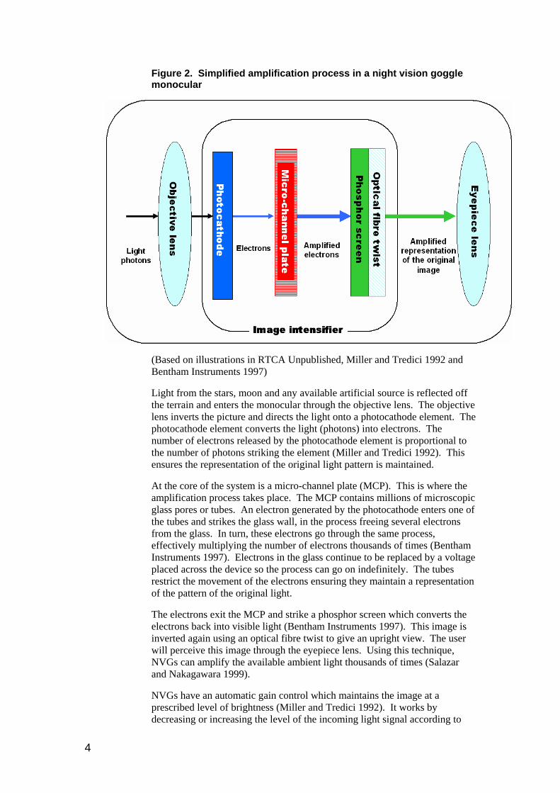
Figure 2. Simplified amplification process in a night vision goggle monocular
(Based on illustrations in RTCA Unpublished, Miller and Tredici 1992 and Bentham Instruments 1997)
Light from the stars, moon and any available artificial source is reflected off the terrain and enters the monocular through the objective lens. The objective lens inverts the picture and directs the light onto a photocathode element. The photocathode element converts the light (photons) into electrons. The number of electrons released by the photocathode element is proportional to the number of photons striking the element (Miller and Tredici 1992). This ensures the representation of the original light pattern is maintained.
At the core of the system is a micro-channel plate (MCP). This is where the amplification process takes place. The MCP contains millions of microscopic glass pores or tubes. An electron generated by the photocathode enters one of the tubes and strikes the glass wall, in the process freeing several electrons from the glass. In turn, these electrons go through the same process, effectively multiplying the number of electrons thousands of times (Bentham Instruments 1997). Electrons in the glass continue to be replaced by a voltage placed across the device so the process can go on indefinitely. The tubes restrict the movement of the electrons ensuring they maintain a representation of the pattern of the original light.
The electrons exit the MCP and strike a phosphor screen which converts the electrons back into visible light (Bentham Instruments 1997). This image is inverted again using an optical fibre twist to give an upright view. The user will perceive this image through the eyepiece lens. Using this technique, NVGs can amplify the available ambient light thousands of times (Salazar and Nakagawara 1999).
NVGs have an automatic gain control which maintains the image at a prescribed level of brightness (Miller and Tredici 1992). It works by decreasing or increasing the level of the incoming light signal according to
4

the level of available light. This protects the NVG electronics and keeps theimage brightness constant when viewing scenes with changing illumination levels.
2.5 Using Night Vision Goggles helmet, the device is adjusted for
d
The pilot is able to look directly at the NVGs to see the scene outside the n
Figure 3. Representations of the NVG image
Once the NVGs are mounted on a pilot’s correct focus and alignment. After the initial set-up the pilot should not neeto make any further adjustments during the flight.
cockpit. The pilot will see a circular image of the terrain in shades of gree(Figure 3).
The pilot can look unaided at the flight controls or instruments by looking under the goggles. To look outside without the aid of goggles, a pilot can either look under the goggles or flip the goggles up using the pivoting mechanism on the NVG mounting interface.
5

3 THE CAPABILITES AND LIMITATIONS OF NIGHT VISION GOGGLES This section examines the main capabilities and limitations of NVGs. Specifically, it provides a comparison of NVG-assisted vision with unaided night vision and unaided day vision. The comparison has been divided into the broad categories of the NVG image, the effect of the operating environment on the NVGs and human factor considerations. The section commences with a description of the basic mechanisms of unaided vision.
3.1 Unaided vision Humans perceive visual information through the eye from light striking receptors in the retina (Miller and Tredici 1992). ‘Cone’ and ‘rod’ light receptor cells are stimulated by light and send signals to the brain. We perceive these signals as vision.
Cone receptors are concentrated in the centre of the retina, are sensitive to colour and provide the greatest visual acuity1 (Miller and Tredici 1992). They are responsible for most visual information in well-lit environments.
Rod receptors are densely spread throughout most of the retina but are absent in the centre. Rod receptors provide much poorer visual acuity than cones (a person with normal vision will have a rod receptor visual acuity of around 6/60) and no discrimination between colours. Rod receptors are more sensitive to light than cone receptors and are responsible for most of our vision in low-light settings (Miller and Tredici 1992).
During visual flight at night a pilot’s rod receptors are responsible for much of the visual information he or she receives. Therefore, visual information is degraded considerably compared with visual flight during the day. For a pilot with normal vision in low-light conditions, the process of degradation may be characterised by:
• a drop in visual acuity from 6/6 to around 6/60 (Miller and Tredici 1992);
• a reduction of the ability to distinguish detail (Miller and Tredici 1992; Sampson, Simpson and Green 1994);
• a degradation or complete loss of the ability to distinguish colour (Miller and Tredici 1992);
• a reduction in definition. Objects will only be distinguished by their contrast or relative lightness/ darkness compared with their background (Miller and Tredici 1992; Sampson, Simpson and Green 1994); and
1 Visual acuity is ‘the relative ability of the human eye to resolve detail and interpret an image’(RTCA 2001b). Visual acuity is most commonly measured by comparing the ability of a given person to distinguish a series of specified letters from a distance of 6 metres compared with normal vision. Normal visual acuity is designated as 6/6, the metric equivalent of the commonly used imperial measurement 20/20. A person with 6/12 could only distinguish at 6 metres what a person with normal vision could distinguish at 12. Visual acuity is one of the most important components of a number of critical visual abilities including depth perception, distance estimation and object recognition (Salazar and Nakagawara 1999; Simpson, Sampson and Green 1994).
6

• a blind spot. As there are no rod receptors in the centre of the eye, the central part of the retina is not sensitive to low level light (Miller and Tredici 1992; Sampson, Simpson and Green 1994).
This degradation of visual information leads to a decrease in a pilot’s ability to recognise objects and estimate distance and depth (Sampson, Simpson and Green 1994). It can result in visual illusions and possibly spatial disorientation2. In addition, the risk of inadvertent entry into IMC (when external visual information is further degraded) is increased as the pilot is less able to see weather conditions ahead (Wilson 1999).
3.2 The Night Vision Goggle image
3.2.1 Visual acuity NVGs provide a vast improvement in visual acuity compared to unaided night vision (Salazar and Nakagawara 1999). Unaided night visual acuity for a person with normal vision is around 6/60 or worse (Miller and Tredici 1992). In comparison, pilots wearing NVG models that are currently available for civil applications have demonstrated a visual acuity of around 6/10 (RTCA 2001b). This is approaching the 6/6 visual acuity required to obtain a Medical Standard 13 certificate under the Civil Aviation Safety Regulations 1998.
In practice, the level of visual acuity attained while using NVGs is variable as it depends on a number of environmental factors, including the amount of ambient light and weather conditions (Rash 2004; Simpson, Sampson and Green 1994).
3.2.2 Field of view and field of regard The Field of View (FOV) is the maximum area that can be seen without any movement of the head or eyes. It is expressed in terms of degrees.
NVGs are limited to a maximum FOV of 40 degrees horizontally and vertically (ITT Industries 2003). This is a significant restriction over normal unaided human vision. Humans have a FOV of around 200 degrees horizontally and 120 degrees vertically, although visual acuity over this range is variable (Miller and Tredici 1992). An optimal FOV is reliant on the correct setting up of the NVGs for different physiological needs.
This restriction of peripheral vision means that there will be a reduction in the visual cues available to the pilot for maintaining spatial orientation (RTCA 2001b). This limitation can be minimised by using head movements to regularly scan the external environment.
The total area that can be scanned with both eye and head movement is called the Field of Regard (FOR). The FOR is limited by the physical limit of head
2 Spatial disorientation occurs when an individual fails to correctly sense the position, motion, or attitude of the aircraft or of himself/herself (ATSB 2003). It is more likely to occur in low visibility where a pilot’s senses sometimes conflict with what is seen on the flight instruments (Federal Aviation Administration 1983).
3 Professional flight crews require a Medical Standard 1 certificate.
7
movement and cockpit design. The FOR of a pilot wearing NVGs should be the same as for unaided vision.
It should be noted that regular scanning of the external environment is also required for unaided night flying due to the limitations of the human eye in low-level illumination settings and to prevent fixation on a bright object (Sampson, Simpson and Green 1994).
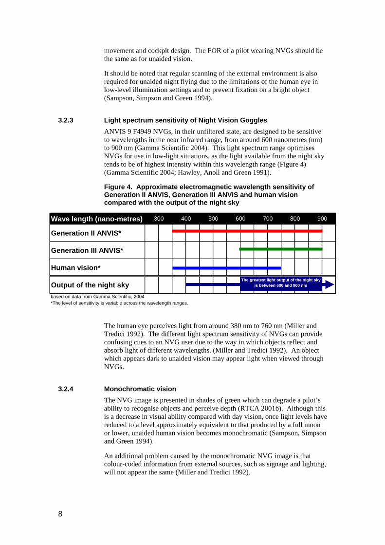
3.2.3 Light spectrum sensitivity of Night Vision Goggles ANVIS 9 F4949 NVGs, in their unfiltered state, are designed to be sensitive to wavelengths in the near infrared range, from around 600 nanometres (nm) to 900 nm (Gamma Scientific 2004). This light spectrum range optimises NVGs for use in low-light situations, as the light available from the night sky tends to be of highest intensity within this wavelength range (Figure 4) (Gamma Scientific 2004; Hawley, Anoll and Green 1991).
Figure 4. Approximate electromagnetic wavelength sensitivity of Generation II ANVIS, Generation III ANVIS and human vision compared with the output of the night sky
The human eye perceives light from around 380 nm to 760 nm (Miller and Tredici 1992). The different light spectrum sensitivity of NVGs can provide confusing cues to an NVG user due to the way in which objects reflect and absorb light of different wavelengths. (Miller and Tredici 1992). An object which appears dark to unaided vision may appear light when viewed through NVGs.
Wave length (nano-metres)
Generation II ANVIS*
Generation III ANVIS*
Human vision*
Output of the night skybased on data from Gamma Scientific, 2004*The level of sensitivity is variable across the wavelength ranges.
300 400 500 600 700 800 900
The greatest light output of the night sky is between 600 and 900 nm
3.2.4 Monochromatic vision The NVG image is presented in shades of green which can degrade a pilot’s ability to recognise objects and perceive depth (RTCA 2001b). Although this is a decrease in visual ability compared with day vision, once light levels have reduced to a level approximately equivalent to that produced by a full moon or lower, unaided human vision becomes monochromatic (Sampson, Simpson and Green 1994).
An additional problem caused by the monochromatic NVG image is that colour-coded information from external sources, such as signage and lighting, will not appear the same (Miller and Tredici 1992).
8
3.2.5 Depth perception and size estimation In good lighting conditions humans rely on a number of techniques for estimating depth and size. These can be broken down into monocular and binocular techniques (Simpson, Sampson and Green 1994).
Binocular cues rely on the slightly different view each eye has of an object (Sampson, Simpson and Green 1994). Binocular cues are not available to an NVG user due to the fixed nature of the NVG image (RTCA 2001b). This is not particularly significant, since the distances between objects and the cockpit is normally too far to use binocular cues (Sampson, Simpson and Green 1994). Furthermore, binocular cues only provide relatively weak depth information (Miller and Tredici 1992).
Monocular techniques are less restricted by distance and can be achieved using one eye alone. The monocular cues likely to be most used by an NVG user are retinal image size and overlay (Miller and Tredici 1992). Retinal image size cues provide information when an NVG user perceives the actual size of an object by comparing the size of the image focused on the retina with the user’s knowledge of the object (Sampson, Simpson and Green 1994). The changing retinal image size of the object as the NVG user moves provides additional cues (Sampson, Simpson and Green 1994). Overlay cues are provided when two objects are overlapped within an image. Based on previous experience, the NVG user is aware that the overlapped object is the furthest away (Sampson, Simpson and Green 1994).
The quality of monocular depth perception is reliant on a number of factors, such as the quality of the NVG image, the distance of the object and the user’s familiarity with the object (Sampson, Simpson and Green 1994). Depth perception and size estimation will therefore vary across different conditions depending on the amount of available light and weather conditions. The effect of the operating environment is discussed below.
It is important to note that depth perception will always be degraded using NVGs compared to normal day time vision. However, in most conditions NVIS should provide a significant improvement over the unaided eye at night.
3.2.6 Dark adaptation The NVG image stimulates a combination of both cone and rod receptors in the eye. When NVGs are removed in a night setting of moderate light, such as a metropolitan area, vision should be close to optimal (RTCA unpublished). If NVGs are removed in a very dark setting, the eyes may take some time to adapt (RTCA unpublished).
3.2.7 After image An orange to brown after-image may occur after the use of NVGs for extended periods (Miller and Tredici 1992). This effect is caused by the green light emitted by the NVGs only stimulating the green light receptors in the eye. When the NVGs are removed the blue and red light receptors become very active while the green receptors become less responsive (Miller and Tredici 1992). The effect will not cause any permanent change in vision.
9
3.2.8 Image defects Some defects in the NVG image occur as part of the goggle manufacturing process. Defects can include bright spots, black spots and other distortions (RTCA unpublished). To a degree, these defects can be tolerated. However, pilots and engineers need to be aware of them and be able to recognise when these defects are above ‘normal’ levels.
3.3 Effects of the operating environment on the Night Vision Goggle image
3.3.1 Light Light can be both beneficial and detrimental to the operation of NVGs. NVGs require some light to operate and provide no benefit in extremely low ambient light conditions. This situation may occur on a clouded night where there is little or no artificial light from the ground or in IMC. In general, the higher the level of light, the better the NVG image quality.
Conversely, direct bright light will decrease the quality of the image by forcing the automatic gain control circuit to turn down. This control protects the goggles from damage and also keeps the image light levels constant. By reducing the quality of the image in darker areas, it effectively increases the level of light required for the NVG to produce an optimal image. Direct bright light can also result in ‘halo’ effects around the light source. These manifest as bands of light around a bright object.
3.3.1.1 Natural light sources
The NVG image quality increases with an increase in the amount of ambient light from stars that is reflected from the terrain (Simpson, Sampson and Green 1994).
The moon can be an advantage or disadvantage to the use of NVIS depending on its location relative to the user. If the moon is behind the helicopter flight path it can increase the amount of light reflecting from the terrain in the direction the helicopter is travelling and improve the quality of the NVG image. However, when the moon is on the same azimuth as the flight path and can be seen through the NVG FOV, the intensity of the moonlight will cause the automatic gain control to reduce the image light gain and therefore reduce image detail (Joint Aviation Authorities 2003). Halo effects may also occur. In essence, the bigger the area of the moon within the field of view, the more problematic it becomes.
Shadows cast by moonlight can cause objects and terrain detail to be significantly degraded from view to the NVG user. Conversely, shadows may improve the contrast in flat featureless areas (RTCA 2001b).
3.3.1.2 Artificial light sources
Artificial light from cities, vehicles and fires will generally assist terrain recognition through NVGs. However, light which is too bright will cause the NVGs to reduce the light gain and possibly result in halo effects. In turn, this may lead to a reduction in image quality.
10

Cockpit instrument lighting and ground lighting may cause similar affects and can be more problematic due to the proximity of the light source to the NVGs.
3.3.2 Weather Cloud, thick fog and dense rain can be perceived using NVGs (RTCA 2001b). NVGs may be able to assist pilots to avoid IMC by improving their ability to identify areas of dense weather.
Pilots wearing NVGs may be able to see through some areas of low density particles such as thin fog, light rain, low density smoke, dust and pollution (Joint Aviation Authorities 2003). Flying in these conditions may reduce the usable energy available to the NVG and decrease the quality of the image (RTCA 2001b). These conditions will affect the contrast of the image. The risk that low density particles pose to an operation can be reduced by training pilots to recognise changes in the NVG image, ensuring thorough weather briefings before flight with an emphasis on NVG effects, ensuring pilots are aware of weather patterns in the flying area, and ensuring pilots occasionally scan the outside scene unaided (RTCA 2001b).
3.3.3 Terrain The reflective qualities of the terrain can affect the perceived quality of the NVG image (Sampson, Simpson and Green 1994).
Desert soil and water reflect light well, making distinct features, such as man-made objects, easy to discern through NVGs (Sampson, Simpson and Green 1994). However, these environments provide little contrast; consequently, depth perception is limited (Sampson, Simpson and Green 1994). The contrast of water is improved by white caps on the surface.
Heavily vegetated rolling terrain has greater contrast, but can still be difficult to interpret due to the lack of recognisable features. However, rivers, roads and structures can facilitate interpretation. The use of terrain is most effective in mountainous areas, where the rapidly changing elevation provides opportunities for high contrast and visual cues (e.g. silhouettes and shadows) (Sampson, Simpson and Green 1994).
3.3.4 Wires Wires are a significant problem for helicopter pilots who are often required to land on unimproved landing sites4. It is difficult to see wires using NVGs (Salazar and Nakagawara 1999). However, it is also very difficult to see wires at night and during the day with unaided vision. NVGs should assist pilots to visually acquire spot the poles and towers which suspend the wires above the ground.
3.3.5 Ground speed The lower the quality of the image, the more time a pilot requires to distinguish objects and terrain (Sampson, Simpson and Green 1994; Salazar
4 Unsurveyed areas which have not been designated as landing sites.
11

and Nakagawara 1999). In conditions which result in lower NVG image quality, a pilot may need to fly at slower ground speeds to allow for this. Alternatively, risk may be mitigated by flying at higher altitudes.
3.3.6 Effective range of Night Vision Goggles The useful range of NVGs is variable, depending on the speed that the aircraft is travelling, the distance or height the aircraft is above a target object, the amount of ambient lighting and the weather conditions. US Army operators have reported NVGs as being an ‘invaluable aide for navigation, situation awareness and obstruction avoidance’ at en-route heights of around 1,500 feet above ground level and even as being a useful tool as high as 8,000 feet (Hawley, Anoll and Green 1991). In general, the lower and slower the flight, the better the NVG image (Salazar and Nakagawara 1999).
3.4 Human factor considerations
3.4.1 Complacency and overconfidence One of the risks associated with NVGs is pilot complacency and overconfidence in the technology. NVGs are reasonably simple to operate and appear very effective. However, NVGs do have limitations. Safety can only be maintained by appropriate initial and ongoing training and sound flight planning so that operations remain within the operational limitations of the NVGs.
3.4.2 Crew resource management A US Army study found that before many NVG helicopter incidents, at least one of the crew members subsequently reported feeling uncomfortable about their situation but did not communicate this to the other crew members (Simpson, Sampson and Green 1994). Such breakdowns in communication can be mitigated by good Crew Resource Management (CRM). In particular, crew members need to communicate with each other regarding what they see to ensure they are all perceiving objects and terrain in the same way.
Effective CRM can help flight crew to detect any NVG airworthiness problems or perceptual difficulties of the crew members. CRM practices can also be applied to ground crew who can provide the pilot with additional information about the terrain and obstacles.
3.4.3 Experience Proficiency and experience in the use of NVGs is an important component in offsetting many of the visual limitations of NVGs (RTCA 2001b). Pilots must be aware of the limitations of the NVG image and its effect on their perception.
3.4.4 Fatigue The additional effort of viewing and interpreting the NVG image, the scanning requirements, and additional weight of the NVGs may be expected to lead to an increase in pilot fatigue (RTCA 2001b; Miller and Tredici 1992).
12

Fatigue can be reduced through appropriate training in the correct adjustment of NVGs to meet the physical and physiological needs of the user and by setting appropriate duty hours.
13

4 NIGHT VISION IMAGING SYSTEMS A NVIS consists of all the elements necessary to successfully and safely operate an aircraft while using NVGs (RTCA 2001a; Joint Aviation Authorities 2003). This includes the NVGs, NVIS compatible cockpit lighting, compatible external lighting, other required aircraft components and equipment, training requirements, operating procedures, and procedures for maintaining the airworthiness of the system.
All of these elements are critical for the safe operation of NVIS. Therefore, adequate resources to support these elements are necessary to ensure safe NVG operations. The following sections address each of these elements.
4.1 Cockpit lighting Conventional cockpit lighting emits a significant amount of light within the same wavelength range to which NVGs are sensitive. This can cause a reduction in contrast, brightness and visual acuity of the NVG image. NVG compatible cockpit lighting is required to prevent these problems.
The major design requirements for NVIS-compatible cockpit lighting include:
• lighting must not decrease the quality of the NVG image;
• lighting needs to remain bright enough within the visible light range to enable a pilot to clearly see the helicopter instruments when looking at them unaided under the NVGs; and
• instrument lighting needs to be adequate for daytime use.
In order to satisfy these requirements, the amount of light emitted by the cockpit lighting within the same wavelength range to which NVGs are sensitive should be minimised.
There are a number of commercial options available to modify the cockpit lighting. They include filters which can be placed over existing cockpit light sources, modified light bulbs and NVG-compatible cockpit floodlighting.
NVGs can be made sensitive to a number of different wavelength ranges depending on light filters fitted to the objective lens. The most suitable wavelength range for a given helicopter depends on the type of instruments fitted in a helicopter and the type of operations anticipated.
The most common wavelength ranges are called Class A and Class B. Class A NVGs are sensitive to light wavelengths of around 625 nm to 900 nm, limiting the available light range for cockpit lighting to blue and green colours. Class B NVGs are sensitive to light within the 665 nm to 900 nm wavelength ranges, thereby allowing additional lighting colours such as orange and yellow. Class B NVGs can be modified further with a notch in the green spectrum to allow users to view Head-up Displays (HUDs) through NVGs.
It is important to note that modifying cockpit lighting is a significant cost component of a NVIS due to the use of specialised materials and the significant work involved in conversion and testing of a helicopter cockpit.
14

4.2 External lighting External lighting can also cause a reduction in the quality of the NVG image. For example, strobe lighting may cause the NVGs to rapidly modify the light gain causing rapid changes in the NVG image which may be irritating and disorientating for the pilot. While it is impractical to modify all external lighting, it may be beneficial to modify the types of lighting that are typically encountered by NVG pilots. This may include lighting at designated landing areas, external helicopter lighting or emergency services lighting on land vehicles.
External lighting can be made compatible by using NVG-compatible filters or globes, by shielding the light from the cockpit, or by implementing operational procedures.
4.3 Other aircraft components and equipment A radar (radio) altimeter may assist in mitigating depth perception problems with NVGs at critical times (i.e. take-off and landing), by providing additional height information. CASA, the Joint Aviation Authorities (JAA) and Federal Aviation Administration (FAA) all mandate that a radar altimeter must be fitted to any helicopter performing NVIS-assisted operations.
Consideration may also be given to methods that reduce glare on the windscreen such as non-reflective cockpit paint and extension of the glare shield (Tavcar 2002). Furthermore, it may be useful to equip flight and ground crew with NIVS-compatible flashlights and utility lights.
4.4 Training NVIS training curricula have been developed by both civil and military organisations around the world. The RTCA has completed a draft Civil Operators’ Training Guidelines for Integrated Night Vision Imaging System Equipment (RTCA unpublished). The RTCA, previously known as the Radio Technical Commission for Aeronautics, is a not-for-profit corporation that develops recommendations and standards on aviation issues that are used by the FAA as a basis for policy. The guidelines provide a detailed curriculum for the development of an operator-specific NVIS training programme including initial and recurrent training. The JAA have also published a similar curriculum (see Joint Aviation Authorities 2003).
A number of training aids have been developed to assist in NVIS training. Resolution charts demonstrate the changes in visual acuity under different environmental conditions. Terrain boards, a three dimensional model of terrain, allow an instructor to demonstrate various effects of lighting, terrain and the moon on the NVG image. Although computer and simulator training are used by the military, the implementation of these facilities may not be cost-effective in the context of civil aviation.
4.5 Operating procedures Appropriate operating procedures should be considered for all aspects of flight which are likely to be affected by the use of NVGs. This includes procedures for:
15
• pre-flight planning. This includes an assessment of celestial illumination, artificial illumination and the likely terrain that will be encountered in addition to the usual considerations such as weather;
• take-off, en-route and landing, including hazard identification;
• emergency situations such as inadvertent IMC entry and NVG failure; and
• transition between NVG aided and unaided vision.
4.6 Airworthiness Consideration needs to be given to the ongoing airworthiness of the NVIS. While the latest NVGs, such as the F4949, have been found to be reliable (Sampson, Simpson and Green 1994), the image intensifying tubes and components of the NVG compatible lighting have limited life spans.
Airworthiness procedures may be considered for ensuring that:
• NVGs are in good working order and are set up optimally for the user;
• aircraft transparencies, such as the windscreen, are in sufficient condition (dirty windscreens can cause reflections which interfere with the NVG image);
• external and internal lighting are in working order and NVIS-compatible where required;
• subsequent aircraft modifications are NVIS-compatible; and
• external and internal lighting remain NVIS-compatible.
Importantly, there may be risks associated with the continuing airworthiness of helicopter fleets which have both NVIS-compatible and non-compatible aircraft. As such, engineers need to ensure that the correct NVIS-compatible parts are used in the correct aircraft.
16

5 THE SAFETY BENEFITS OF NIGHT VISION IMAGING SYSTEMS
5.1 Current operations under Night Visual Flight Rules In addition to the Day VFR requirements, the Australian Night Visual Flight Rules (NVFR) dictate a number of additional restrictions on night flying. A pilot must hold an appropriate NVFR rating specified in the Civil Aviation Orders, Part 40, Section 40.2.2, the aircraft must be equipped with the instruments specified in the Civil Aviation Order, Section 20.18 and the pilot must comply with the Lowest Safety Altitude (LSALT) requirements specified in the Civil Aviation Regulations 1988 Section 174B. In addition, there are a number of landing site requirements advised by the Civil Aviation Advisory Publications.
During NVFR operations a pilot is expected to maintain knowledge of the position of the horizon by reference to external environmental features or by reference to the aircraft instruments. The instruments which provide horizon information are similar to those available for Instrument Flight Rules (IFR) operations.
There are currently no requirements under the NVFR for a pilot to consider the amount of external visual reference likely to be available for the en-route phase of a flight. The pilot is not required to assess the likely quality of celestial illumination, the amount of terrain lighting or the presence of a visual horizon before the flight commences. In fact, the pilot should feel competent enough to operate safely without any external visual cues from shortly after takeoff until approaching the destination aerodrome. The VMC minima and runway lighting requirements mean that an external visible reference will be available to the pilot during the departure and arrival segments of a flight.
There is no regulatory requirement for the NVFR rating competencies to be demonstrated during regular flight reviews or otherwise at recurrent intervals. There is no requirement for the holder of a NVFR rating to have demonstrated any recent instrument flying proficiency prior to conducting a flight at night.
5.2 Night Visual Flight Rules helicopter operations Typically, a powerful searchlight or “nitesun” is used for helicopter NVFR operations to aid navigation to the target area, reconnaissance of the landing area, landing and subsequent take off. The searchlight is mounted externally on the helicopter and can be positioned remotely. The searchlight can be focused by the pilot to increase or decrease the width of the circle of light. The effectiveness of a searchlight is limited by altitude, the relatively small amount of terrain it can illuminate and the speed at which it can be moved by the motors controlling its direction.
17

5.3 Applications of Night Vision Imaging Systems NVIS is of potential benefit to a wide range of helicopter operations, including emergency medical services (EMS), search and rescue, fire fighting and law enforcement.
Australia has significant numbers of remote, low-population areas which have little artificial illumination. Helicopter operations, such as EMS, are often required to fly day and night throughout these areas. Furthermore, they frequently involve unscheduled flights with little advance notice to unimproved landing sites.
For these kinds of operations NVGs may assist the pilot to:
• maintain spatial orientation by providing improved horizon and terrain detail;
• avoid obstacles and terrain by providing greater visual detail;
• visually navigate more efficiently;
• identify suitable landing sites more easily;
• continually monitor suitable emergency landing sites while en-route; and
• identify IMC conditions more easily.
These abilities should assist pilots in take-off, cruise, descent to land and landing phases of flight.
In addition, NVGs will assist pilots to identify the target area by providing greater terrain detail and the ability to distinguish sources of low-level light such as distant vehicle lights or hand held torches. This has significant advantages for search and rescue and EMS operations.
Since the helicopter is likely to be based in a well-lit, metropolitan area at an improved landing site, NVIS is unlikely to be required in the initial take-off and final landing phases of flight. However, it may be preferable to use NVG-aided vision throughout the operation for consistency of operational procedures. This would avoid the pilot from having to change from unaided to NVG-aided vision during the flight.
5.3.1 Flying below Lowest Safe Altitude Under current Australian regulations during NVFR pilots must fly above the appropriate Lowest Safe Altitude (LSALT)5 except during the take-off and landing phases of a flight. NVGs may allow the pilot to fly safely at heights below LSALT, depending on the environmental conditions and the subsequent quality of the NVG image. Flying below LSALT may be beneficial for avoiding IMC, for navigation purposes, for optimum terrain avoidance, for identifying and approaching unprepared landing sites and to achieve operational requirements.
5 1000 foot above the highest obstacles within 10 miles of the aircraft, or under radar control and using a radar
LSALT.
18
6 INTERNATIONAL CIVIL USE OF NIGHT VISION GOGGLES From an international perspective, the potential safety benefits of NVGs for civil operations around the world are becoming increasingly recognised. In fact, a number of aviation regulators across the world have approved NVG-assisted operations or are in the process of doing so. As a result, there is significant international experience in NVG operations that can be used to develop NVIS in Australia.
6.1 Switzerland Helicopter pilots working for the Swiss Air-Rescue service ‘Rega’ have been operating with NVGs since 1988. Rega has stated that it believes NVGs provide significant benefits to their NVFR helicopter operations. NVGs assist Rega pilots to observe meteorological conditions to avoid IMC, assist in the early recognition of obstacles and terrain and to identify accident sites more easily (Schneibel 2004). Rega have had no inadvertent IMC entries since the introduction of NVGs. The mountainous nature of their operating environment makes this a significant safety issue.
6.2 United States of America The FAA began approving the use of NVGs on a case by case basis in the late 1990s. In February 1999, Rocky Mountain Helicopters conducted the first FAA approved civil NVG assisted flight. Since 1999, a number of other operators have received approval for similar operations.
Considerable progress has been made in the US towards developing standards and streamlined approval of NVG-assisted operations and equipment. FAA approval of NVG-assisted operations in the US is guided by the material in the three RTCA documents:
• Minimum Operational Performance Standards for Integrated Night Vision Imaging System Equipment;
• Concept of Operations: Night Vision Imaging System for Civil Operators; and
• Civil Operators’ Training Guidelines for Integrated Night Vision Imaging System Equipment (unpublished).
These three documents contain considerable information on a complete NVIS, including the technical specifications of the hardware, recommended training practices and operating procedures.
The FAA released a Technical Standing Order (TSO) for NVGs on 20 September 2004 (Federal Aviation Administration 2004b). The TSO allows manufacturers to apply for blanket approval of their NVG product rather than the product having to go through a lengthy approval process each time it is installed in a new helicopter.
19

The FAA regards NVGs as a tool for assisting flights under current regulations rather than enabling additional capabilities. The FAA states that ‘the use of NVGs will not enable any mode of flight that cannot be flown within the framework of the existing regulations’ (Federal Aviation Administration 2004a).
6.3 United Kingdom A number of United Kingdom (UK) police helicopters are now undertaking NVIS operations. Increasing interest in NVIS operations stemmed predominantly from an AAIB report on the crash of a police Eurocopter in 2002. In their findings, the AAIB recommended in August 2003 that the UK Civil Aviation Authority (UK CAA)
‘require that Police Air Operators Certificate (AOC) holders review the safety benefits provided by the use of helmet mounted night vision goggles (NVGs) with a view to the introduction of NVGs for helicopter operations conducted at night in support of the police in areas of limited cultural lighting, particularly in hilly or mountainous regions.’ (AAIB 2003).
The UK CAA accepted this recommendation in September 2003 and has since been developing NVG standards with the FAA and the JAA. It is understood that these standards will be based on the RTCA standards.
6.4 New Zealand To date, there are no civil aviation rules in New Zealand which restrict the use of NVGs for helicopter operations. However, the helicopter industry and the Civil Aviation Authority (NZ CAA) of New Zealand have recognised the need for NVG standards (Civil Aviation Authority 2004).
The Aviation Industry Association Air Rescue/Air Ambulance Division, representing the New Zealand EMS helicopter industry, has been tasked to prepare and present a package to the NZ CAA addressing the use of NVGs. The NZ CAA has requested that the package address the major components of safe flight using NVIS, including crew training, acquisition of equipment, cockpit lighting, operating procedures, ongoing currency and ongoing airworthiness of equipment.
The NZ CAA expects that, subject to its acceptance of the industry package, NVIS operations will proceed. The NZ CAA is considering the introduction of civil aviation rules for NVIS some time in the future.
20

7 THE STATUS OF NIGHT VISION GOGGLES IN AUSTRALIA
7.1 Australian Night Vision Imaging Systems trial A trial of a NVIS was undertaken by the Victorian Police Air Wing (VPAW), with the cooperation of CASA, in 2002 (Tavcar 2002). VPAW conducted the trial with four ANVIS 6 Generation III NVGs, one set of F4949 NVGs and a temporary Class A standard cockpit lighting modification. While part of the trial was focused on assessing the use of NVIS for police-specific operations, the trial also assessed the use of NVIS for operations types relevant to other civil helicopter operators.
VPAW concluded, from the results of the trial, that NVIS is a potentially useful tool for flying below LSALT outside metropolitan areas, emergency service delivery at night and IFR operations. The report stated that NVIS is ‘necessary for both safety and operational capability’ (Tavcar 2002).
7.2 The future of Night Vision Goggles operations in Australia In December 2004, CASA introduced procedures for CASA Flying Operations Inspectors (FOIs) to approve certain types of NVG helicopter operations in a Compliance Management Instruction (CMI). Copies of the annexes to the CMI are available from local CASA Area Offices6. The four annexes to the CMI outline the procedures for applying for approved NVG helicopter operations and the requirements for NVG flight approval. In addition, the CMI annexes outline the crew training requirements and the operational restrictions for approved NVG flight.
In order for CASA to consider an application, an operator must demonstrate a clearly defined operational need for NVG operations. CASA requires a comprehensive NVIS package to be implemented before operations can take place. This package must include;
• ANVIS 9 Model number F4949 NVGs;
• a helicopter equipped with NVG compatible lighting meeting the standards set out in the RTCA Document 275 Minimum Operational Performance Standards for Integrated Night Vision Imaging System Equipment or the US Military standard MIL-STD-3009 Lighting, Aircraft, Night Vision Imaging System Compatible;
• suitably qualified flight crew who have passed a specified NVG training course or who are otherwise suitably qualified and experienced in using NVGs;
• requirements for ongoing recent experience; and
6 A copy can be obtained in Australia by telephoning 131757 during office hours, and asking for your local Area Office.
21

• operational procedures.
CASA will consider for approval NVG operations which satisfy the requirements using Civil Aviation Regulation 1988 reg 174B(4)7. This regulation allows CASA to approve of operations below night LSALT, and it has previously been used by CASA to approve of other related operations such as those using searchlights.
The CMI has been implemented by CASA as an interim measure. The Aviation Safety Standards Division of CASA is currently developing operational and airworthiness standards for NVIS operations using NVGs for safe NVFR operations carried out below LSALT. The project is related to CASR Part 133B for certain aerial work operations and is being carried out by a joint industry/CASA working group.
7 See CASA web site <http://www.casa.gov.au/avreg/rules/1988regs.htm>
22

8 CONCLUSION With proper implementation, NVGs have the potential to enhance the safety of visual flight at night. Compared with unaided night vision, NVGs increase a pilot’s ability to see the horizon, terrain, observe meteorological conditions and to identify objects. NVGs assist a pilot to maintain spatial orientation, to avoid hazards and inadvertent IMC entry and to visually navigate. CASA has recently recognised the benefits of NVGs and it is anticipated that it is only a matter of time before civil NVG operations take place in Australia.
The introduction of any new technology, however, has inherent risks. Most notably, this includes the risk that pilots can overestimate the capabilities of the technology and fly into inappropriate conditions for safe flight. As this report has shown, however, NVGs do not have the ability to turn night into day. In essence, NVGs do not replicate the colours, field of view, and level of visual acuity achieved in day vision. It is important that the relationship between the operating environment and NVG image quality is understood by operators and pilots. This relationship needs to be considered in the operator’s risk management and flight planning processes.
The risks associated with NVG use can be mitigated by implementing a comprehensive NVIS package. This may include:
• NVGs;
• helicopter modifications to ensure that cockpit lighting is compatible;
• other external lighting modifications;
• initial and on-going training for flight crew;
• operational procedures; and
• airworthiness requirements.
It is essential that sufficient resources are available to ensure the safe and effective use of NVGs. Specifically, sufficient resources need to be allocated for the initial cost of the NVGs, the additional costs in the set up and maintenance of other required hardware, the initial training of crew and support staff, as well as the ongoing costs of recurrent training and airworthiness.
23
9 REFERENCES ATSB 2003, Air Safety Occurrence Report: 200102083, Australian Transport Safety Bureau, Canberra, <http://www.atsb.gov.au/aviation/occurs/occurs_detail.cfm?ID=473>.
Bentham Instruments 1997, NVIS Compatibility: A primer, Bentham Instruments, Berkshire.
Civil Aviation Authority 2004, Email correspondence with the Australian Transport Safety Bureau on 1st October 2004.
Federal Aviation Administration 1983, Pilot’s Spatial Disorientation, Advisory Circular 60-4A, Washington, D.C.
Federal Aviation Administration 2004a, Flight Standards Handbook for Air Transportation: Night Vision Imaging Systems, FAA HBAT 04-02, Washington, D.C.
Federal Aviation Administration 2004b, Technical Standard Order: Night Vision Goggles, FAA TSO-C164, Washington D.C.
Gamma Scientific 2004, Measuring spectral performance of night vision devices, tutorial paper, viewed 20 September 2004, <http://www.gamma-sci.com/tutorials.html>.
Global Security 2005, Night Vision Goggles, online paper, viewed 7 January 2005, <http://www.globalsecurity.org/military/systems/ground/nvg.htm>.
Hawley, R. J., Anoll, R. K. and Green, D. 1991, Rotorcraft night vision goggle evaluation, DOT/FAA/RD-91/11, Federal Aviation Administration, Washington, D.C.
ITT Industries 2003, Night vision goggles/image intensifier set AN/AVS-9 (F4949 Series), promotional pamphlet, viewed 20 September 2004, <http://www.ittnv.com/itt/Active/MilProductPages/AviationSystems/ProductPage/186>.
Joint Aviation Authorities 2003, Night Vision Imaging Systems (NVIS) Operations, JAA Temporary Guidance Leaflet Number 34, Hoofddorp.
Miller, R. E. and Tredci, T. J. 1992, Night vision manual for the flight surgeon, USAF Special Report No. AL-SR-1992-0002, Armstrong Laboratory, Brooks Air Force Base.
Rash, C E. 2004. Helmet Mounted Displays: Design Issues for Rotary-Wing Aircraft. US Army Aeromedical Research Laboratory, viewed 19 November 2004, <http://www.usaarl.army.mil/hmdbook/cp_0002_contents.htm>.
RTCA 2001a, Minimum operational performance standards for integrated night vision imaging system equipment, RTCA/DO-275, RTCA, Washington, D.C.
RTCA 2001b, Concept of operations: Night vision imaging system for civil operators, RTCA/DO-268, RTCA, Washington, D.C.
24

RTCA unpublished, Civil operators’ training guidelines for integrated night vision imaging system equipment, Unpublished report no. 103-04/SC196-032, RTCA, Washington, D.C.
Salazar, G. J. and Nakagawara, V. B. 1999. Night Vision Goggles in Civilian Helicopter Operations. The Federal Air Surgeon’s Medical Bulletin Fall 1999, Federal Aviation Administration, viewed 29 September 2004, <http://www.cami.jccbi.gov/AAM-400A/FASMB/FAS9903/night.htm>.
Sampson, W. T., Simpson, G. B. and Green, D. L. 1994, Night vision goggles in Emergency Medical Services (EMS) Helicopter, FAA report DOT/FAA/RD-94/21, Federal Aviation Administration, Washington, D.C.
Schneibel, W. 2004. Night vision goggles, unpublished presentation notes, Rega.
Tavcar, M. 2002. Night Vision: Post Trial Report, Victoria Police Air Wing, Essendon.
Wilson, D. R. 1999, Darkness increase risk of flight. Human factors and aviation medicine, November-December 1999, Flight Safety Foundation, Alexandria.
25

ATS
B
Nig
ht V
isio
n G
oggl
es in
Civ
il H
elic
opte
r Ope
ratio
ns
ISB
N 1
877
071
94 3