nma metals s1 p6 corrosion cathodic protection
TRANSCRIPT
7/29/2019 NMA Metals s1 p6 Corrosion Cathodic Protection
http://slidepdf.com/reader/full/nma-metals-s1-p6-corrosion-cathodic-protection 1/13
Proceedings of Metal 2004 National Museum of Australia Canberra ACT 4-8 October 2004
ABN 70 592 297 967
© Published by the National Museum of Australia www.nma.gov.au
Corrosion and cathodic protection of iron in seawater: a case study of the
James Matthews (1841)
M. Heldtberg a, I.D. MacLeod b1, V.L. Richards b
aBevtoftgade 4, 2nd Floor, 1736 Copenhagen V, Denmark bWestern Australian Museum, Cliff Street, Fremantle, Western Australia 6160, Australia
Abstract
Pre-disturbance measurements of the in-situ corrosion properties of iron fittings on the snow brig James
Matthews (1841) have been used as conservation management tools for the site. The wreck of the former slavetrader is historically significant and the potential impact of continued industrial activities associated with nearbydredging activities necessitated in-situ cathodic protection of exposed iron fittings. A laboratory simulation study
of the impact of pH and chloride content on the corrosion of cast iron and mild steel was conducted. There was alinear relationship between the corrosion rate of cast iron and the log of chloride ion concentration in the pHrange 7.8< pH >5.5 with only a small pH effect noted for the given range of conditions. Studies on a 19th century
mild steel sample indicated that the corrosion rate was linearly dependent on the square root of the chloride ionconcentration and the corrosion rate fell in a linear fashion as the pH was increased to strongly alkaline solutionsof sodium hydroxide.
Keywords: conservation, corrosion-simulation, cast-iron, mild-steel, seawater, in-situ treatment, sacrificialanodes.
1. Introduction
The wreck of the James Matthews was chosen as a test case for the Western Australian Museum to trial theminimal intervention site management strategies of the ICOMOS (1997) charter on the protection andmanagement of underwater cultural heritage. The wreck is a rare example of a ship built as a slave-tradingvessel, which is located about 15km south of the Museum Conservation laboratories and the industrial history of
Cockburn Sound meant that any stabilisation activities would not have major negative impacts on an area thathas suffered decades of industrial abuse. The Western Australian Museum has previously reported a number of in-situ treatments of iron fittings associated with historic shipwrecks (Carpenter & Richards, 1993; MacLeodet.al., 1986; MacLeod, 1986, 1989a, 1989b, 1993a, 1993b, 1995, 1996a, 1996b, 1998a, 1998b; Richards, 1996,2001; Richards & Carpenter, 1998) and the most recent studies have included measurements on modern navalvessels that have been deliberately sunk to act as artificial reefs (Richards, 2003a, 2003b; Richards & MacLeod,
2004). Periodic monitoring of corrosion potentials makes it possible to predict the rate at which a metal objectdeteriorates and to determine the most appropriate time to recover the object (MacLeod, 1996b, 1989b, 2002).
The benefits of attaching sacrificial anodes to metal objects include an immediate decrease in corrosion rate andcommencement of an active conservation treatment. As the polarity of the object changes from positive tonegative the removal of chloride ions is enhanced, resulting in less time required for conservation treatments inthe laboratory (Carpenter & MacLeod, 1993; Gregory, 1999, 2000; MacLeod, 1993b; Soerensen & Gregory,
1998).It is believed that the 107-ton snow brig James Matthews was built in France in the 1820’s as a wooden
vessel with copper sheathing fastened with copper, iron and wooden treenails, and was wrecked on 22nd
July1841. The wreck is located about 100m offshore in Cockburn Sound and is relatively protected against rough seaconditions in all weathers, with the exception of northwesterly winds, which predominate in winter. The wreck
lies at an approximate depth of 1.8m±0.4m, covering an area about 25m x 7m x 2m. It is mostly buried to a depthof approximately 1.5-2m in calcareous sand. The water temperature increased from 17ºC in September to 24ºC in
1
Corresponding author: TEL: +61 8 9427 2839: FAX: +61 8 9472 1157:email: [email protected]
75
7/29/2019 NMA Metals s1 p6 Corrosion Cathodic Protection
http://slidepdf.com/reader/full/nma-metals-s1-p6-corrosion-cathodic-protection 2/13
Proceedings of Metal 2004 National Museum of Australia Canberra ACT 4-8 October 2004
ABN 70 592 297 967
© Published by the National Museum of Australia www.nma.gov.au
December 2000, but there was no significant temperature gradient throughout the water column. The seawater column was measured on-site between the 6-7 December 2000 and the mean temperature was 24.3±0.1ºC, the
pH 8.25±0.04, the salinity 34.5±0.7ppt, the average dissolved oxygen content 7.81±0.11ppm and the average
redox potential was 0.142±0.072V2. These measurements indicate an open circulation aerobic marineenvironment.
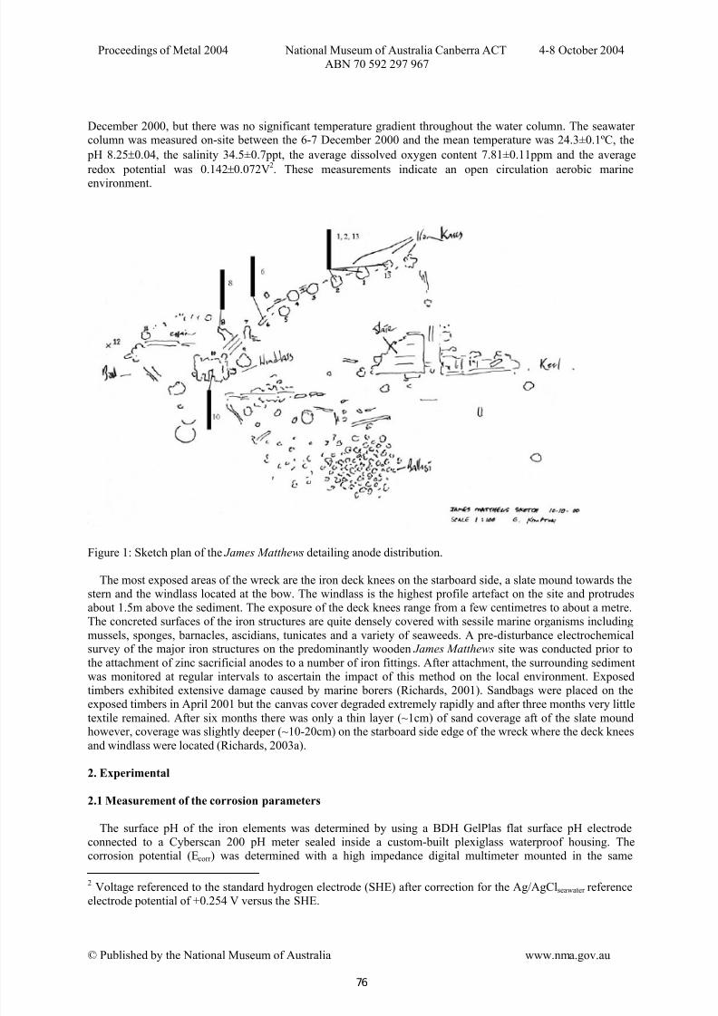
Figure 1: Sketch plan of the James Matthews detailing anode distribution.
The most exposed areas of the wreck are the iron deck knees on the starboard side, a slate mound towards thestern and the windlass located at the bow. The windlass is the highest profile artefact on the site and protrudesabout 1.5m above the sediment. The exposure of the deck knees range from a few centimetres to about a metre.The concreted surfaces of the iron structures are quite densely covered with sessile marine organisms including
mussels, sponges, barnacles, ascidians, tunicates and a variety of seaweeds. A pre-disturbance electrochemicalsurvey of the major iron structures on the predominantly wooden James Matthews site was conducted prior to
the attachment of zinc sacrificial anodes to a number of iron fittings. After attachment, the surrounding sedimentwas monitored at regular intervals to ascertain the impact of this method on the local environment. Exposedtimbers exhibited extensive damage caused by marine borers (Richards, 2001). Sandbags were placed on theexposed timbers in April 2001 but the canvas cover degraded extremely rapidly and after three months very little
textile remained. After six months there was only a thin layer (~1cm) of sand coverage aft of the slate moundhowever, coverage was slightly deeper (~10-20cm) on the starboard side edge of the wreck where the deck knees
and windlass were located (Richards, 2003a).
2. Experimental
2.1 Measurement of the corrosion parameters
The surface pH of the iron elements was determined by using a BDH GelPlas flat surface pH electrodeconnected to a Cyberscan 200 pH meter sealed inside a custom-built plexiglass waterproof housing. Thecorrosion potential (Ecorr ) was determined with a high impedance digital multimeter mounted in the same
2
Voltage referenced to the standard hydrogen electrode (SHE) after correction for the Ag/AgCl seawater referenceelectrode potential of +0.254 V versus the SHE.
76
7/29/2019 NMA Metals s1 p6 Corrosion Cathodic Protection
http://slidepdf.com/reader/full/nma-metals-s1-p6-corrosion-cathodic-protection 3/13
Proceedings of Metal 2004 National Museum of Australia Canberra ACT 4-8 October 2004
ABN 70 592 297 967
© Published by the National Museum of Australia www.nma.gov.au
waterproof housing, connected to a platinum working electrode and a Ag/AgClseawater reference electrode. Thereference electrode was calibrated by measuring the voltage difference between a standard Ag/AgCl3M KCl
electrode that had been previously calibrated using a standard saturated quinhydrone solution in a pH 4 buffer solution. The procedure for measuring surface pH and Ecorr was to drill through the concretion and corrosion
layers on the artefact until the residual metal surface was reached. Penetration of the concretion was effectedusing a 16mm masonry drill bit attached to a pneumatic drill powered off a SCUBA tank. Immediately after removal of the drill bit the pH electrode was inserted and held against the metal surface until the minimum pHreading was recorded. The Ecorr was measured by establishing electrical contact between the metal and the
platinum electrode that had been placed into the drill hole. The Ecorr values were characterised by a steadyvoltage that varied by only one millivolt.
A standard divers depth gauge and thermometer unit was attached to the housing, as was a vernier calliper.After the corrosion parameters were measured, the total corrosion/concretion depth was determined with thevernier calliper.
2.2 Fabrication of the zinc anodes
Corrosion protection of iron objects in seawater can be effected by establishing electrical contact with a zinc
anode via an insulated copper wire cable. Four zinc anodes were purchased for the experiment and one of themhad three connection points so it could be simultaneously attached to three separate iron objects in order to gaugethe impact of a three-fold increase in the surface area of the objects being protected on the efficiency of this
anode arrangement.The connection points between the crimped terminal at the exposed end of an insulated copper electrical wire
and the cast iron G-clamp were silver soldered (50% Ag, 35% Cu, 15% Zn) and sealed using heat-shrink epoxymastic ([email protected]). After attaching the commercial zinc anodes by securing themachined screw thread of the G-clamp via a pre-drilled hole through the concretion, the pH and E corr weremeasured through a second drill hole and also directly on the anode. The impact of the anode corrosion products
on the marine environment was quantified via analysis of the zinc content in the surrounding sediments, whichwere collected from beneath the anodes in polycarbonate corers (4.5x30cm) each time the corrosion parameterswere measured. A piece of wood across the top opening of the tube protected the tube from being shattered as itwas hammered into the seabed. Four baseline sediment samples were collected from the positions where theanodes were to be placed near iron deck knees 2, 6, 8 and the windlass 10 as shown in Figure 1. A controlsample was collected off-site, approximately 20m south from deck knee 2.
2.3 Corrosion simulation equipment
The cast iron and steel electrodes used in the corrosion simulation experiments were imbedded in epoxy resinafter connecting insulated copper wires to the metal by brazing. Electrode surface area calibrations were performed using chronoamperometry with an Amel 551 Potentiostat connected to a flat bed XY-t recorder. The
grey cast iron electrodes were fabricated from a commercially available washbasin, which had a very similar composition and microstructure to cast iron objects on the wreck. The cast iron electrode had an effective surfacearea of 12.6cm
2(surface roughness 13.6), a density of 7.3gcm
-3and a metal composition of Fe 96%, C 3.30%, Si
2.6%, Mn 0.46%, P 0.59%, S 0.06%, Cu 0.03% and Ni 0.01%. The 19th century mild steel electrode, whichapproximates wrought iron, had a surface area of 22.7cm2 (surface roughness 44), a density of 7.76gcm-3 and anelemental composition of Fe 99.98%, C 0.18%, Si 0.06%, Mn 0.69%, P 0.06%, S 0.06%, Cu 0.02% and Ni0.02%. The real surface areas of the electrodes were separately determined using standard electrochemical
techniques. The details of the method can be found in standard texts on the electrochemistry of solid electrodes based on comparison of the diffusion currents to standardised platinum electrodes and those observed on the ironsystems (Adams, 1969). The aforementioned parameters were inserted into the software program, SoftCorr
TMII,
that calculated the corrosion rate of the metal surfaces exposed to the test solutions.The effect of pH and chloride concentration on the corrosion rate of wrought iron and cast iron was assessed
using the SoftCorr TM II program and a EG&G model potentiostat VersaStat (model 253) potentiostat using a
standard three electrode configuration that sees the current pass between two graphite rod electrodes and theworking iron electrode. The voltage is measured between the working electrode and a 3M KCl calomel referenceelectrode that was connected to the test solution via a Luggin capillary and a 2M NaNO 3 salt bridge (PrincetonApplied Research, 1990). In order to avoid spurious concentration effects all variations in chloride concentration
experiments were carried out at the same ionic strength, using NaNO3 as the inert electrolyte. Generally, themost reliable method for analysis of the current voltage curves involved the use of one or both types of the Tafel
77
7/29/2019 NMA Metals s1 p6 Corrosion Cathodic Protection
http://slidepdf.com/reader/full/nma-metals-s1-p6-corrosion-cathodic-protection 4/13
Proceedings of Metal 2004 National Museum of Australia Canberra ACT 4-8 October 2004
ABN 70 592 297 967
© Published by the National Museum of Australia www.nma.gov.au
analyses that fitted the curves to standard corrosion theory. A typical potentiodynamic scan involved recordingof the relationship between the logarithm of the corrosion current and the voltage as it was scanned ±250mV
from the rest potential or Ecorr of the metal in the test solution. The Tafel slope relates to the region on the plotwhere there was a linear relationship between the log current and the voltage. Typically five Tafel slope scans
were performed for each set of experimental conditions. The analyses sought to minimise the difference in thecalculated result and the observed result as represented by a quantity defined as chi2. A final chi2 value of zeroindicated a perfect fit of the data with typical values for good fits ranging between two and 100.
2.4 Laboratory corrosion experiments on cast iron and mild steel electrodes
The test solutions consisted of normal seawater and a range of chloride concentrations and pH values thatreflect the increased alkalinity and reduced chlorinity that occurs during in-situ conservation treatments. The pre-disturbance in-situ pH was 6.85±0.27 with a mean Ecorr of –0.224±0.022V vs SHE. The local seawater pH was7.76 with a chloride concentration of 0.56M and the effect of chlorides at 0.01M and 0.001M at the same pH was
examined. A 1.5M chloride solution at pH 5.50 represented a concreted microenvironment and the corrosion rateat 0.1M, 0.01M and 0.001M chloride were also examined. The NaCl solutions were prepared using AR gradechemicals from BDH and the pH was buffered to pH 5.50 and 7.76.
3. Results
Core samples were collected prior to anode attachment (29/11/01) and then 48 days (16/1/02) after attachment. The first 2cm and the next 10cm of the 30cm sediment cores were analysed for free zinc by GeotechPty. Ltd and the results are listed in Table 1.
Table 1: Concentration of zinc in sediment samples collected before and after the use of sacrificial anodes.
Sample Name 29/11/2001
0-2 cm fraction[Zn] mg/kg
16/01/2002
0-2 cm fraction[Zn] mg/kg
29/11/2001
2-12 cm fraction[Zn] mg/kg
16/01/2002
2-12 cm fraction[Zn] mg/kg
Core 2 3 8 200 2 710
Core 6 5 18 400 2 980
Core 8 5 259 000 2 25 200
Core 10 12 1 380 2 53
Baseline 5 192 000#
2 12 500
# This data point appears to be erroneous and may reflect sampling error.
4. Discussion
The colonisation of wrecks, which is dependent on a number of parameters including water depth,temperature and the season of the year, results in the separation of the anodic and cathodic reaction surfaces.Hard calcareous layers will reduce the corrosion rate of iron by virtue of the physical barrier it provides to
dissolved oxygen (MacLeod, 1989b). In-situ pH and Ecorr measurements have shown that a relative acidic andreducing environment exists inside the concretion in contact with the corroding iron where pH values can be as
low as 4.2 and the chloride concentration higher than 1.5M. Acidity develops as a consequence of hydrolysis of the primary corrosion product FeCl2 according to the equation described by North (1982).
2 FeCl2 + 2 H2O → β{Fe(OH)2FeCl2} + 2H+
+ 2 Cl-............................................................1
Both laboratory and shipwreck data indicates that corrosion is limited by the rate of the cathodic electrode process, i.e. by the rate of reduction of dissolved oxygen (MacLeod, 1995), thus the overall corrosion rate of ironis dependent on the flux of dissolved oxygen to the concreted surface. Analysis of data from a number of shipwreck sites shows that the logarithm of the corrosion rate of iron decreases linearly with increasing water
depth (MacLeod, 2003). For iron objects that are totally buried under sediment the principal cathodic reactioninvolves the reduction of water, which is often facilitated by anaerobic bacteria.
78
7/29/2019 NMA Metals s1 p6 Corrosion Cathodic Protection
http://slidepdf.com/reader/full/nma-metals-s1-p6-corrosion-cathodic-protection 5/13
Proceedings of Metal 2004 National Museum of Australia Canberra ACT 4-8 October 2004
ABN 70 592 297 967
© Published by the National Museum of Australia www.nma.gov.au
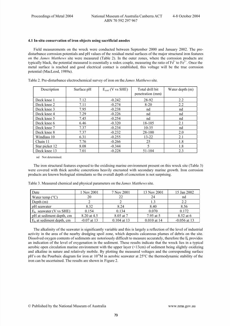
4.1 In-situ conservation of iron objects using sacrificial anodes
Field measurements on the wreck were conducted between September 2000 and January 2002. The pre-disturbance corrosion potentials and pH values of the residual metal surfaces of the major structural iron features
on the James Matthews site were measured (Table 2). In the outer zones, where the corrosion products aretypically black, the potential measured is essentially a redox couple, measuring the ratio of Fe3+ to Fe2+. Once themetal surface is reached and good electrical contact is established, this voltage will be the true corrosion potential (MacLeod, 1989a).
Table 2. Pre-disturbance electrochemical survey of iron on the James Matthews site.
Description Surface pH Ecorr (V vs SHE) Total drill bit penetration (mm)
Water depth (m)
Deck knee 1 7.12 -0.242 28-92 2.2
Deck knee 2 7.11 -0.274 8-20 2.2
Deck knee 3 7.95 -0.238 nd nd
Deck knee 4 7.29 -0.226 nd ndDeck knee 5 7.45 -0.254 nd nd
Deck knee 6 6.46 -0.320 18-105 2.1
Deck knee 7 7.37 -0.234 10-35 nd
Deck knee 8 7.37 -0.232 28-100 2.0
Windlass 10 6.31 -0.255 13-22 2.1
Chain 11 7.76 -0.266 25 1.8
Star picket 12 8.08 -0.344 5 1.8
Deck knee 13 7.01 -0.228 51-104 2.3
nd Not determined.
The iron structural features exposed to the oxidising marine environment present on this wreck site (Table 3)
were covered with thick aerobic concretions heavily encrusted with secondary marine growth. Iron corrosion products are known biological stimulants so the overall depth of concretion is not surprising.
Table 3. Measured chemical and physical parameters on the James Matthews site.
Date 1 Nov 2001 7 Nov 2001 13 Nov 2001 15 Jan 2002
Water temp (°C) 20 22 24 nd
Depth (m) 2 2 1.3 2.2
pH seawater 8.32 8.24 8.40 8.56
Eh seawater (V vs SHE) 0.154 0.134 0.070 0.172
pH at sediment depth, cm 8.20 at 4.5 8.05 at 7 7.95 at 5 8.52 at 6
Eh at sediment depth, cm -0.07 at 13 0.104 at 13 0.010 at 14 -0.056 at 13
The alkalinity of the seawater is significantly variable and this is largely a reflection of the level of industrialactivity in the area of the nearby dredging spoil zone, which deposits calcareous plumes of debris on the site.Dissolved oxygen contents of sediments are notoriously difficult to measure accurately, therefore the Eh providesan indication of the level of oxygenation in the sediment. These results indicate that the wreck lies in a typicalaerobic open circulation marine environment with the upper layer (<13cm) of sediment being slightly oxidizing
and alkaline in nature and relatively mobile. By plotting the measured voltages and the corresponding surface
pH’s on the Pourbaix diagram for iron at 10-6M in aerobic seawater at 25°C the thermodynamic stability of the
iron can be ascertained. The results are shown in Figure 2.
79
7/29/2019 NMA Metals s1 p6 Corrosion Cathodic Protection
http://slidepdf.com/reader/full/nma-metals-s1-p6-corrosion-cathodic-protection 6/13
Proceedings of Metal 2004 National Museum of Australia Canberra ACT 4-8 October 2004
ABN 70 592 297 967
© Published by the National Museum of Australia www.nma.gov.au
0 1 2 3 4 5 6 7 8 9 10 11 12 pH
Eh(v)
0.8
0.6
0.4
0.2
0.0
-0.2
-0.4
-0.6
-0.8
-1.0
Fe2+
Fe3O
4
Fe
FeO.OH
Fe3+
active
passiveactive
passive
immune
(b)
(a)
1
2
3 & 4
z
5
6
7
8
windlass 10 11 chain 12 star picket
z
13
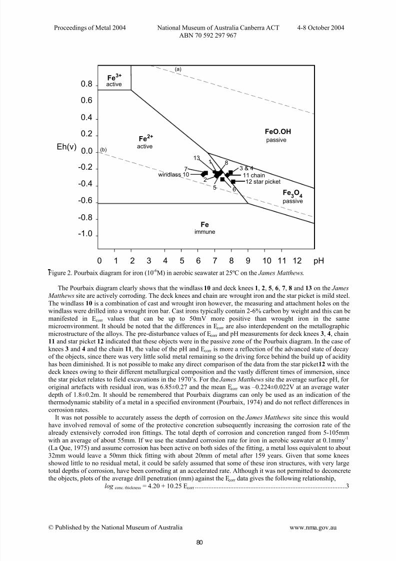
Figure 2. Pourbaix diagram for iron (10
-6M) in aerobic seawater at 25ºC on the James Matthews.
The Pourbaix diagram clearly shows that the windlass 10 and deck knees 1, 2, 5, 6, 7, 8 and 13 on the James
Matthews site are actively corroding. The deck knees and chain are wrought iron and the star picket is mild steel.The windlass 10 is a combination of cast and wrought iron however, the measuring and attachment holes on thewindlass were drilled into a wrought iron bar. Cast irons typically contain 2-6% carbon by weight and this can bemanifested in Ecorr values that can be up to 50mV more positive than wrought iron in the samemicroenvironment. It should be noted that the differences in Ecorr are also interdependent on the metallographicmicrostructure of the alloys. The pre-disturbance values of Ecorr and pH measurements for deck knees 3, 4, chain
11 and star picket 12 indicated that these objects were in the passive zone of the Pourbaix diagram. In the case of
knees 3 and 4 and the chain 11, the value of the pH and Ecorr is more a reflection of the advanced state of decayof the objects, since there was very little solid metal remaining so the driving force behind the build up of acidity
has been diminished. It is not possible to make any direct comparison of the data from the star picket 12 with thedeck knees owing to their different metallurgical composition and the vastly different times of immersion, sincethe star picket relates to field excavations in the 1970’s. For the James Matthews site the average surface pH, for original artefacts with residual iron, was 6.85±0.27 and the mean Ecorr was –0.224±0.022V at an average water
depth of 1.8±0.2m. It should be remembered that Pourbaix diagrams can only be used as an indication of thethermodynamic stability of a metal in a specified environment (Pourbaix, 1974) and do not reflect differences in
corrosion rates.It was not possible to accurately assess the depth of corrosion on the James Matthews site since this would
have involved removal of some of the protective concretion subsequently increasing the corrosion rate of thealready extensively corroded iron fittings. The total depth of corrosion and concretion ranged from 5-105mm
with an average of about 55mm. If we use the standard corrosion rate for iron in aerobic seawater at 0.1mmy-1
(La Que, 1975) and assume corrosion has been active on both sides of the fitting, a metal loss equivalent to about
32mm would leave a 50mm thick fitting with about 20mm of metal after 159 years. Given that some kneesshowed little to no residual metal, it could be safely assumed that some of these iron structures, with very largetotal depths of corrosion, have been corroding at an accelerated rate. Although it was not permitted to deconcretethe objects, plots of the average drill penetration (mm) against the Ecorr data gives the following relationship,
log conc. thickness = 4.20 + 10.25 Ecorr ..........................................................................................3
80
7/29/2019 NMA Metals s1 p6 Corrosion Cathodic Protection
http://slidepdf.com/reader/full/nma-metals-s1-p6-corrosion-cathodic-protection 7/13
Proceedings of Metal 2004 National Museum of Australia Canberra ACT 4-8 October 2004
ABN 70 592 297 967
© Published by the National Museum of Australia www.nma.gov.au
for which the R 2 value was 0.989. This equation shows that there is a direct relationship between the log of thecorrosion rate of iron, as measured by the concretion thickness and the corrosion potential. This assumes a direct
connection between marine growth and the availability of iron as a growth stimulant. This data indicates that thein-situ Ecorr data does provide a direct measure of the way in which the corrosion rate varies over the site.
Sandbagging the site in April 2001 resulted in a general lowering of the Ecorr values since sediment had builtup in the more exposed regions of the site and the deck knees and other higher profile material were partiallyreburied. Owing to the archaeological significance of the James Matthews and the mobility of the sediment, andsince by November 2001 the previously reburied areas were re-exposed, it was decided to stabilise the heavily
degraded knees in-situ through the application of sacrificial anodes. During the galvanic corrosion processchloride ions, which have accumulated as a result of the in-situ corrosion reaction, migrate towards thesurrounding seawater. Although aluminium is more economical than zinc it has a tendency to passivate inaerobic seawater and it is unsatisfactory when buried under sediment, whereas zinc performs well in bothenvironments and has good overall current efficiency (Morgan, 1993). The number of anodes and their size iscalculated according to standard formulas in the cathodic protection literature, which take into account the
wetted area of the iron structure to be protected (Shrier, 1976). Sacrificial zinc anodes were attached to selecteddeck knees (1, 2, 13, 6 and 8) and the windlass (10) and the effectiveness of the treatment was gauged over time.The results of the electrochemical survey of the protected iron structures are shown in Table 4.
Table 4. Electrochemical survey of the protected iron objects during treatment.
Description of Iron Material
pHobject 7 days
Ecorr vsSHE
7 days
Ecorr vsSHE
69 days
pH anode
7 daysEcorr anode
vs SHE7 days
Ecorr anodevs SHE69 days
Deck knee 13 8.01 -0.348 -0.466
Deck knee 1 n.d. -0.520 -0.558
Deck knee 2 8.35 -0.608 -0.590
7.02 -0.658 -0.676
Deck knee 6 8.04 -0.738 -0.732 6.83 -0.748 -0.748
Deck knee 8 8.08 -0.453 -0.532 7.46 -0.638 -0.662
Windlass 10 8.35 -0.570 -0.608 7.43 -0.602 -0.620
Deck knees 1, 2 and 13 were attached to the same anode with a spider-like arrangement and the Ecorr data
showed better protection after a further nine weeks. After 10 weeks of use the anodes had a loose covering of corrosion products that were cleared before Ecorr was measured; the pH of the windlass anode was 5.74, whichshowed it is actively corroding. The surface pH of the iron objects after one week of treatment was directlylinked to their Ecorr values by the relationship,
pHobject = 4.76 –0.64 Ecorr ........................................................................................................4
Deck knee 6 did not conform to this relationship, which had an R 2
of 0.9383, as it was originally corroding atthe lowest rate and had become totally protected with the anode. The other fittings generally demonstrated amore cathodic Ecorr after a further nine weeks of treatment than that which was observed after one week. Theincrease in the pH of the iron objects is a direct measure of the in-situ treatment consuming acidity at the metal-concretion interface. Corrosion potential values of the iron objects on the James Matthews site before and after cathodic protection are shown on a Pourbaix diagram for iron in aerobic seawater (Figure 3).
Interpretation of the James Matthews pre-disturbance data is facilitated by a comparison with the Xantho shipwreck, where the mean Ecorr of 25 measurements was –0.268V, at an average water depth of 3.5m (MacLeod
1986). This value is marginally more cathodic than the mean James Matthews Ecorr value of -0.258V, as would be expected from the deeper site conditions. After the zinc anodes had been attached the drop in the corrosion potential was in the range 0.417<δ Ecorr >0.236V, which is a greater degree of protection than was obtained on the Xantho stern where the drop in Ecorr was only 0.115V but the anode was protecting a much greater surface area
(MacLeod, 1986, 1996b). The submarine Resurgam had an average Ecorr of –0.393V and this fell by 0.040Vimmediately after zinc anodes had been attached (Gregory, 2000), which indicated good connection but that the
large vessel had not been polarised within the diving period. These voltage drops on the James Matthews siteexceed the nominal value of 0.150V needed for reasonable protection. Full cathodic protection is afforded atvoltages more negative than –0.610V (Shrier, 1976), therefore only deck knee 6 and the windlass 10 hadeffectively ceased corroding but the other fittings were undergoing active conservation treatment in-situ
(Morgan, 1993).
81
7/29/2019 NMA Metals s1 p6 Corrosion Cathodic Protection
http://slidepdf.com/reader/full/nma-metals-s1-p6-corrosion-cathodic-protection 8/13
Proceedings of Metal 2004 National Museum of Australia Canberra ACT 4-8 October 2004
ABN 70 592 297 967
© Published by the National Museum of Australia www.nma.gov.au
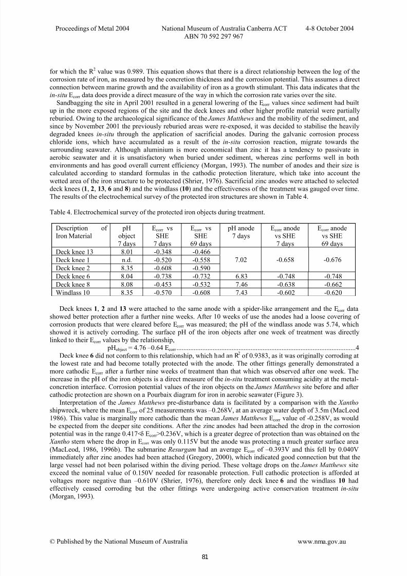
Figure 3. Pourbaix diagram for iron (10-6M) in aerobic seawater at 25ºC, showing pre-disturbance measurementsand those after two months of cathodic protection.
All the data on the James Matthews confirmed that the overall rate of iron corrosion has been dramaticallyreduced. The anode attached to deck knee 6 had achieved the greatest protection and this was reflected in the
surface pH of the anode being the lowest at 6.83, as the result of hydrolysis of Zn2+
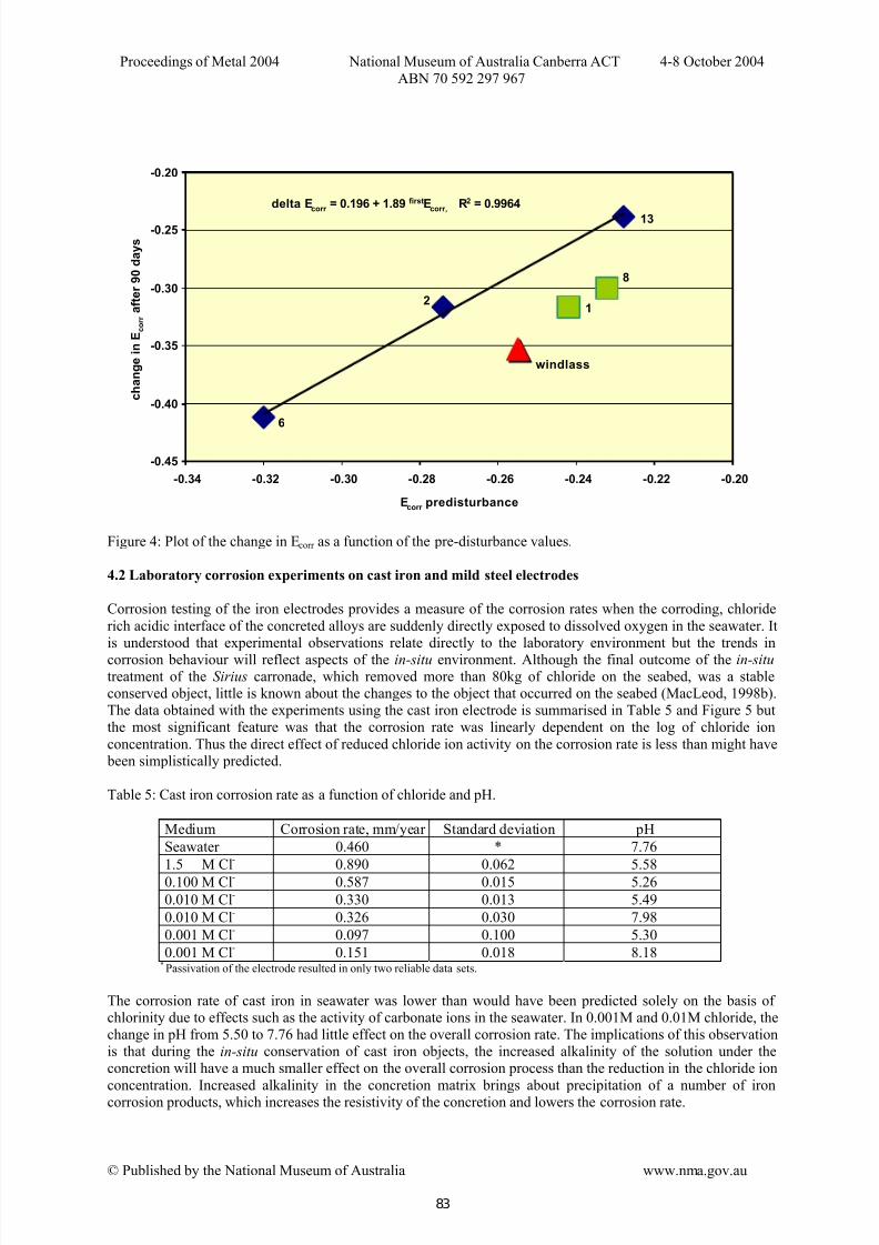
from the corrosion reaction.The differences in the apparent efficiency of the anodes is likely to be due to the surface areas being protectedrather than being due to poor electrical connection to the objects. When the data in Table 4 was compared withthe pre-disturbance values it was found that after 90 days, the changes in E corr were related to the original Ecorr
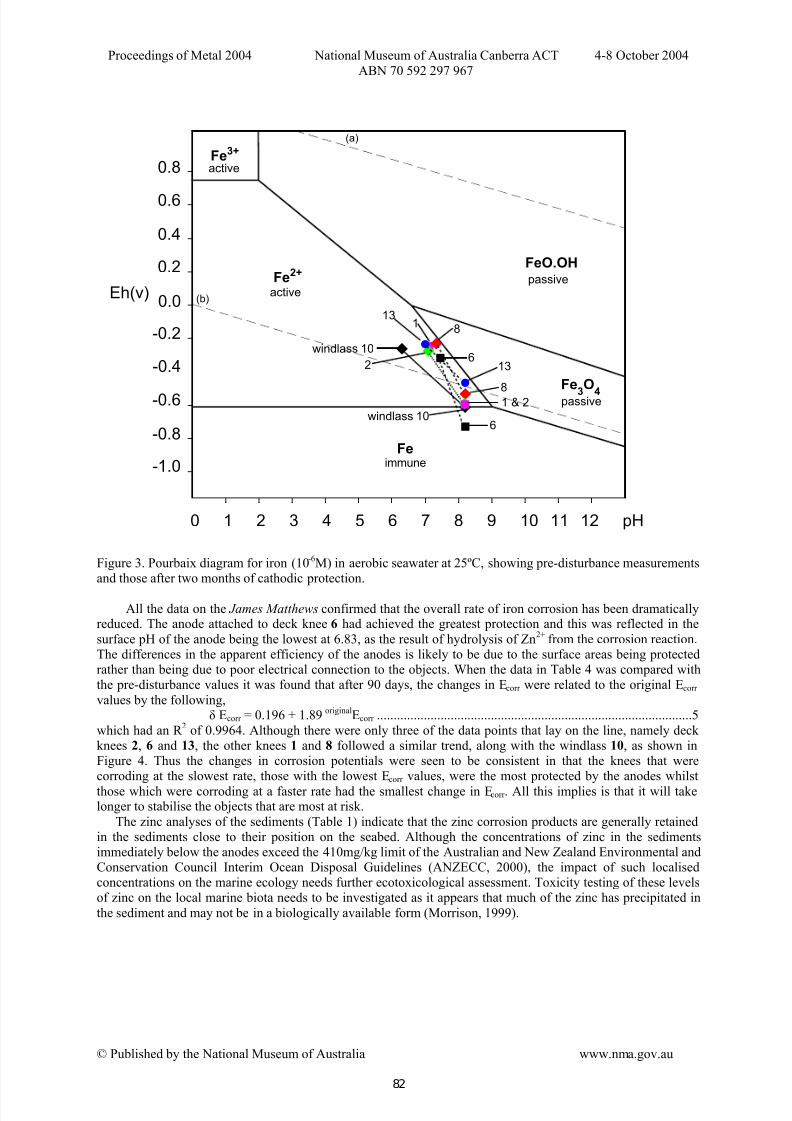
values by the following,δ Ecorr = 0.196 + 1.89 originalEcorr ..............................................................................................5
which had an R 2
of 0.9964. Although there were only three of the data points that lay on the line, namely deck knees 2, 6 and 13, the other knees 1 and 8 followed a similar trend, along with the windlass 10, as shown inFigure 4. Thus the changes in corrosion potentials were seen to be consistent in that the knees that werecorroding at the slowest rate, those with the lowest Ecorr values, were the most protected by the anodes whilst
those which were corroding at a faster rate had the smallest change in Ecorr . All this implies is that it will takelonger to stabilise the objects that are most at risk.
The zinc analyses of the sediments (Table 1) indicate that the zinc corrosion products are generally retainedin the sediments close to their position on the seabed. Although the concentrations of zinc in the sedimentsimmediately below the anodes exceed the 410mg/kg limit of the Australian and New Zealand Environmental andConservation Council Interim Ocean Disposal Guidelines (ANZECC, 2000), the impact of such localisedconcentrations on the marine ecology needs further ecotoxicological assessment. Toxicity testing of these levelsof zinc on the local marine biota needs to be investigated as it appears that much of the zinc has precipitated in
the sediment and may not be in a biologically available form (Morrison, 1999).
0 1 2 3 4 5 6 7 8 9 10 11 12 pH
Eh(v)
0.8
0.6
0.4
0.2
0.0
-0.2
-0.4
-0.6
-0.8
-1.0
Fe2+
Fe3O
4
Fe
FeO.OH
Fe3+
active
passiveactive
passive
immune
(b)
(a)
1
2
6
8
windlass 10 z
13
z
81 & 2
6windlass 10
13
82
7/29/2019 NMA Metals s1 p6 Corrosion Cathodic Protection
http://slidepdf.com/reader/full/nma-metals-s1-p6-corrosion-cathodic-protection 9/13
Proceedings of Metal 2004 National Museum of Australia Canberra ACT 4-8 October 2004
ABN 70 592 297 967
© Published by the National Museum of Australia www.nma.gov.au
delta Ecorr = 0.196 + 1.89 firstEcorr, R2 = 0.9964
-0.45
-0.40
-0.35
-0.30
-0.25
-0.20
-0.34 -0.32 -0.30 -0.28 -0.26 -0.24 -0.22 -0.20
Ecorr predisturbance
c h a n g e i n E
c o r r a f t e r 9 0 d a y s
windlass
6
2
13
8
1
Figure 4: Plot of the change in Ecorr as a function of the pre-disturbance values.
4.2 Laboratory corrosion experiments on cast iron and mild steel electrodes
Corrosion testing of the iron electrodes provides a measure of the corrosion rates when the corroding, chloride
rich acidic interface of the concreted alloys are suddenly directly exposed to dissolved oxygen in the seawater. Itis understood that experimental observations relate directly to the laboratory environment but the trends in
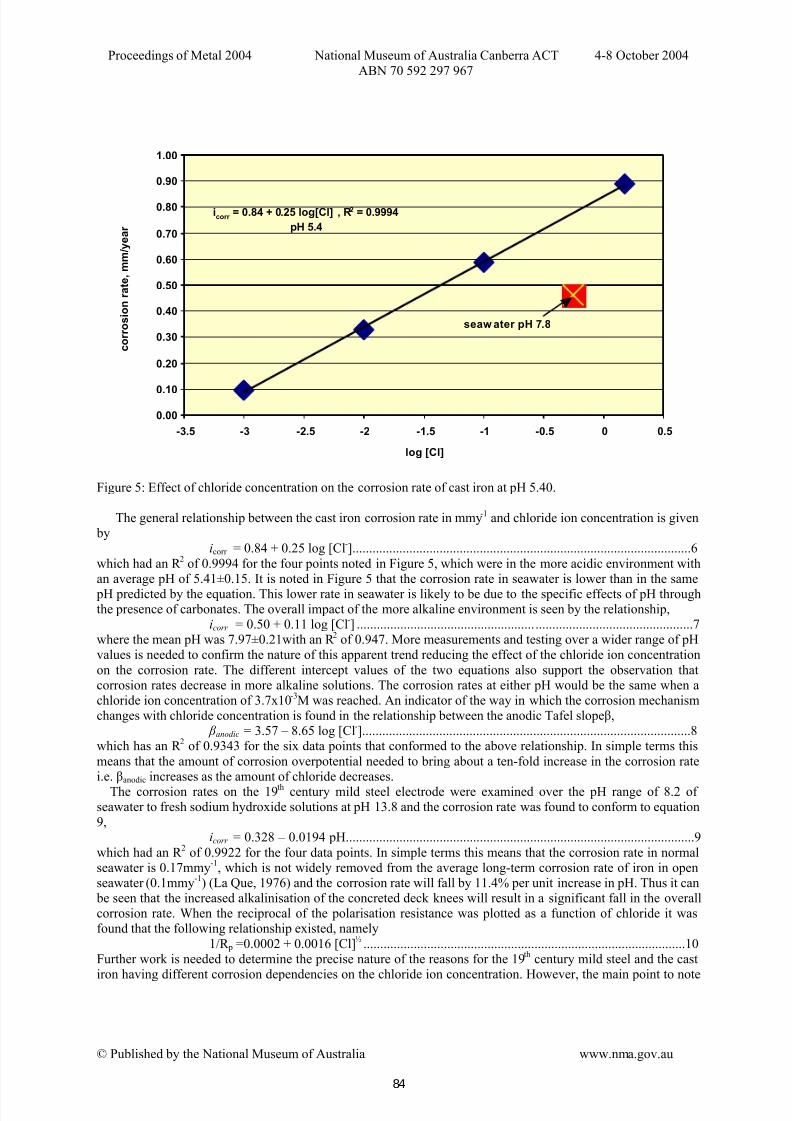
corrosion behaviour will reflect aspects of the in-situ environment. Although the final outcome of the in-situ treatment of the Sirius carronade, which removed more than 80kg of chloride on the seabed, was a stableconserved object, little is known about the changes to the object that occurred on the seabed (MacLeod, 1998b).The data obtained with the experiments using the cast iron electrode is summarised in Table 5 and Figure 5 butthe most significant feature was that the corrosion rate was linearly dependent on the log of chloride ion
concentration. Thus the direct effect of reduced chloride ion activity on the corrosion rate is less than might have been simplistically predicted.
Table 5: Cast iron corrosion rate as a function of chloride and pH.
Medium Corrosion rate, mm/year Standard deviation pH
Seawater 0.460 * 7.76
1.5 M Cl-
0.890 0.062 5.58
0.100 M Cl-
0.587 0.015 5.26
0.010 M Cl-
0.330 0.013 5.49
0.010 M Cl-
0.326 0.030 7.98
0.001 M Cl-
0.097 0.100 5.30
0.001 M Cl-
0.151 0.018 8.18* Passivation of the electrode resulted in only two reliable data sets.
The corrosion rate of cast iron in seawater was lower than would have been predicted solely on the basis of chlorinity due to effects such as the activity of carbonate ions in the seawater. In 0.001M and 0.01M chloride, thechange in pH from 5.50 to 7.76 had little effect on the overall corrosion rate. The implications of this observationis that during the in-situ conservation of cast iron objects, the increased alkalinity of the solution under theconcretion will have a much smaller effect on the overall corrosion process than the reduction in the chloride ion
concentration. Increased alkalinity in the concretion matrix brings about precipitation of a number of ironcorrosion products, which increases the resistivity of the concretion and lowers the corrosion rate.
83
7/29/2019 NMA Metals s1 p6 Corrosion Cathodic Protection
http://slidepdf.com/reader/full/nma-metals-s1-p6-corrosion-cathodic-protection 10/13
Proceedings of Metal 2004 National Museum of Australia Canberra ACT 4-8 October 2004
ABN 70 592 297 967
© Published by the National Museum of Australia www.nma.gov.au
icorr = 0.84 + 0.25 log[Cl] , R2 = 0.9994
pH 5.4
0.00
0.10
0.20
0.30
0.40
0.50
0.60
0.70
0.80
0.90
1.00
-3.5 -3 -2.5 -2 -1.5 -1 -0.5 0 0.5
log [Cl]
c o r r o s i o n r a t e , m m / y e a r
seaw ater pH 7.8
Figure 5: Effect of chloride concentration on the corrosion rate of cast iron at pH 5.40.
The general relationship between the cast iron corrosion rate in mmy-1 and chloride ion concentration is given by
icorr = 0.84 + 0.25 log [Cl-].....................................................................................................6
which had an R 2
of 0.9994 for the four points noted in Figure 5, which were in the more acidic environment withan average pH of 5.41±0.15. It is noted in Figure 5 that the corrosion rate in seawater is lower than in the same
pH predicted by the equation. This lower rate in seawater is likely to be due to the specific effects of pH throughthe presence of carbonates. The overall impact of the more alkaline environment is seen by the relationship,
icorr = 0.50 + 0.11 log [Cl-] ..................................................... ...............................................7where the mean pH was 7.97±0.21with an R 2 of 0.947. More measurements and testing over a wider range of pHvalues is needed to confirm the nature of this apparent trend reducing the effect of the chloride ion concentration
on the corrosion rate. The different intercept values of the two equations also support the observation thatcorrosion rates decrease in more alkaline solutions. The corrosion rates at either pH would be the same when achloride ion concentration of 3.7x10
-3M was reached. An indicator of the way in which the corrosion mechanism
changes with chloride concentration is found in the relationship between the anodic Tafel slope β, β anodic = 3.57 – 8.65 log [Cl-]..................................................................................................8
which has an R 2 of 0.9343 for the six data points that conformed to the above relationship. In simple terms this
means that the amount of corrosion overpotential needed to bring about a ten-fold increase in the corrosion ratei.e. βanodic increases as the amount of chloride decreases.
The corrosion rates on the 19th century mild steel electrode were examined over the pH range of 8.2 of seawater to fresh sodium hydroxide solutions at pH 13.8 and the corrosion rate was found to conform to equation9,
icorr = 0.328 – 0.0194 pH........................................................................................................9
which had an R 2
of 0.9922 for the four data points. In simple terms this means that the corrosion rate in normalseawater is 0.17mmy
-1, which is not widely removed from the average long-term corrosion rate of iron in open
seawater (0.1mmy-1
) (La Que, 1976) and the corrosion rate will fall by 11.4% per unit increase in pH. Thus it can be seen that the increased alkalinisation of the concreted deck knees will result in a significant fall in the overallcorrosion rate. When the reciprocal of the polarisation resistance was plotted as a function of chloride it wasfound that the following relationship existed, namely
1/R p =0.0002 + 0.0016 [Cl]½
................................................................................................10Further work is needed to determine the precise nature of the reasons for the 19
thcentury mild steel and the cast
iron having different corrosion dependencies on the chloride ion concentration. However, the main point to note
84
7/29/2019 NMA Metals s1 p6 Corrosion Cathodic Protection
http://slidepdf.com/reader/full/nma-metals-s1-p6-corrosion-cathodic-protection 11/13
Proceedings of Metal 2004 National Museum of Australia Canberra ACT 4-8 October 2004
ABN 70 592 297 967
© Published by the National Museum of Australia www.nma.gov.au
is that the use of in-situ conservation treatments for iron fittings will not only remove chloride ions but willreduce the corrosion rate through a combination of increased alkalinity and decreased chlorinity.
5. Conclusion
Samples of some 19th century steel, which simulates aspects of the corrosion behaviour of wrought iron, have been shown to increase the corrosion rate with the square root dependence on the chloride concentration. Thisdependence may be a reflection of diffusion controlled processes dominating the oxidation of the iron metal.
Cast iron electrodes showed an increased corrosion rate that increased linearly with the logarithm of theconcentration of chloride. The differences in corrosion mechanism of the iron alloys are likely to be due to their different microstructures. The site of the James Matthews was used to demonstrate the value of obtaining pre-disturbance survey data on the in-situ pH, Ecorr and thickness of the iron marine concretion. The application of zinc sacrificial anodes to effect in-situ conservation of the objects has been shown to be an effective method of site stabilisation.
Acknowledgements
Christian Degrigny assisted the initial stages of this project during the special marine conservation program atEvtek in Finland. The support of Michael McCarthy of the Western Australian Maritime Museum as projectleader of the James Matthews wreck site is gratefully acknowledged.
References
Adams, R. N., (1969) Electrochemistry at solid electrodes, M. Dekker, Inc., New York, p. 402.
ANZECC/ARMCANZ (2000) Australian and New Zealand guidelines for fresh and marine water quality.
National Water Quality Management Strategy Paper No 4, Australian and New Zealand Environment andConservation Council & Agriculture and Resource Management Council of Australia and New Zealand,Canberra.
Carpenter, J. & MacLeod, I.D., (1993) Conservation of corroded iron cannon and the influence of degradation ontreatment times, in ICOM-Committee for Conservation, Preprints 10th Triennial Conference, Washington, Volume
II, pp. 759-766.
Carpenter, J. & Richards, V., (1993) Conservation in Galle, Conservation Management Report from Sri Lanka,unpublished report, Western Australian Maritime Museum, pp. 79.
Gregory, D., (1999) Monitoring the effect of sacrificial anodes on the large iron artefacts on the Duart Point
wreck, 1997, International Journal of Nautical Archaeology, 28.2, pp. 164-173.
Gregory, D., (2000) In-situ corrosion studies on the submarine Resurgam. A preliminary assessment of her stateof preservation, Conservation and Management of Archaeological Sites, pp. 93-100.
ICOMOS (1997) International Council on Monuments and Sites. News. First Edition. Charter on Underwater Cultural Heritage.
La Que, F.L. (1975) Corrosion by seawater. Behaviour of metals and alloys in seawater in The Corrosion Handbook , ed. H.H. Uhlig, J., Wiley and Sons, New York, pp. 383-430.
MacLeod, I.D., (1986) Conservation of the steam ship Xantho, AICCM Bulletin, vol. 1, 3 & 4, pp. 66-94.
MacLeod, I.D., (1989a) The application of corrosion science to the management of maritime archaeologicalsites, Bulletin of the Australian Institute for Maritime Archaeology, 32(2), pp. 7-16.
MacLeod, I. D., (1989b) The electrochemistry and conservation of iron in sea water, Chemistry in Australia, pp.
227-229.
85
7/29/2019 NMA Metals s1 p6 Corrosion Cathodic Protection
http://slidepdf.com/reader/full/nma-metals-s1-p6-corrosion-cathodic-protection 12/13
Proceedings of Metal 2004 National Museum of Australia Canberra ACT 4-8 October 2004
ABN 70 592 297 967
© Published by the National Museum of Australia www.nma.gov.au
MacLeod, I.D., (1993a) Conservation assessment, in Historic Shipping on the River Murray, ed. S. Kenderine,State Heritage Branch, Department of Environment and Land Management, pp. 273-282.
MacLeod, I. D., (1993b) Metal corrosion on shipwrecks: Australian case studies, Trends in Corrosion Research,
pp. 221-245.
MacLeod, I.D., (1995) In-situ corrosion studies on the Duart Point wreck, 1994, The International Journal Nautical Archaeology, 24.1, pp. 53-59.
MacLeod, I.D., (1996a) An in-situ study of the corroded hull of HMVS Cerberus (1926), in The Proceedings of the 13
thInternational Corrosion Congress, Melbourne, November 1996 , pp. 1-10.
MacLeod, I. D., (1996b) In-situ conservation of cannon and anchors on shipwreck sites, in Archaeological Conservation and its Consequences, Preprints of the Contributions to the Copenhagen Congress, ed. Ashok Roy
and Perry Smith, ICC, pp. 111-115.
MacLeod, I.D., (1998a) In-situ corrosion studies on iron and composite wrecks in South Australian waters:
implications for site managers and cultural tourism, Bulletin of the Australian Institute for Maritime Archaeology, 22, pp. 81-90.
MacLeod, I. D., (1998b) In-situ corrosion studies on iron shipwrecks and cannon. The impact of water depth andarchaeological activities on corrosion rates, in Proceedings of the International Conference on MetalsConservation, ed. William Mourey and Luc Robbiola, Draguignan-Figanieres, pp. 116-124.
MacLeod, I.D., (2002) Conservation of the iron shipwreck City of Launceston (1865) and modelling its decay, Preprints for ICOM-CC Triennial Meeting, Rio de Janeiro, Brazil September 2002, Vol II, pp. 871-877.
MacLeod, I. D., (2003) Metal corrosion in Chuuk Lagoon: A survey of iron shipwrecks and aluminium aircraft,Report to the US National Parks Authority, Pacific Division, San Francisco, USA, pp. 1-92.
MacLeod, I.D., North, N.A. & Beegle, C.J., (1986) The excavation, analysis and conservation of shipwreck sites,in Preventative Measures During Excavation and Site Protection. ICCROM Conference, Ghent, 1985, pp. 113-
131.
Morgan, J,. (1993) Cathodic Protection, second edition, NACE publication, Houston Texas, pp. 1-519.
Morrison, P. F., (1999) Biological Monitoring of the HMAS Swan, unpublished report, submitted to TheGeographe Bay Artificial Reef Society Inc., pp. 1-7.
North, N. A., (1982) Corrosion products on marine iron, Studies in Conservation, 27, pp. 75-83.
Pourbaix, M.J.M., (1974) Atlas of Electrochemical Equilibria in Aqueous Solutions, 2nd ed., NationalAssociation of Corrosion Engineers (NACE), Texas, pp. 1-644.
Princeton Applied Research (1990) User’s Guide to Model 352/252 SoftCorr TM II. Corrosion Measurement &
Analysis Software, EG&G Princeton Applied Research, P.O. Box 2565, Princeton, NJ 08543-2565 USA.Richards, V.L., (1996), The Degradation and Conservation of Natural Organic Polymers From HistoricShipwrecks, Masters of Philosophy Thesis, Murdoch University, Perth, Australia, pp. 1-270.
Richards, V. L., (2001) James Matthews (1841) conservation pre-disturbance survey report , unpublished report,
Department of Materials Conservation, Western Australian Museum, pp. 1-37.
Richards, V.L., (2003a) Corrosion survey of the former naval vessel HMAS Hobart. November 2003 ,unpublished report, Department of Materials Conservation, Western Australian Museum, Perth.
86
7/29/2019 NMA Metals s1 p6 Corrosion Cathodic Protection
http://slidepdf.com/reader/full/nma-metals-s1-p6-corrosion-cathodic-protection 13/13
Proceedings of Metal 2004 National Museum of Australia Canberra ACT 4-8 October 2004
ABN 70 592 297 967
© Published by the National Museum of Australia www.nma.gov.au
Richards, V.L., (2003b) James Matthews (1841) reburial project. Conservation research design. August 2003,unpublished report, Department of Materials Conservation, Western Australian Museum, pp. 1-33.
Richards, V.L. & Carpenter, J., (1998) 1996 Conservation management report. Site L, in Sri Lanka Department
of Archaeology Report on the Joint Sri-Lanka-Australia-Netherlands Galle Harbour Project 1996-1997. Archaeology, History, Conservation and Training , eds, J. Green, S. Devendra and R. Parthesius, SpecialPublication No. 4, The Australian National Centre of Excellence for Maritime Archaeology, Fremantle, pp. 50-60.
Richards, V.L. & MacLeod, I.D., (2004) Corrosion survey of the former naval vessel HMAS Perth, unpublishedreport, Department of Materials Conservation, Western Australian Museum, Perth.
Shrier, L.L., (1976) Corrosion, 2nd ed., Newnes-Butterworths, London Vols 1 and 2.
Soerensen, B. & Gregory, D., (1998) In-situ preservation of artefacts in Nydam Mose, in Proceedings of the International Conference on Metals Conservation, ed. William Mourey and Luc Robbiola, Draguignan-Figanieres, pp. 94-99.