noise assessment modelling - dpti web viewthe design and construction of the xxxxxxxxxxxx. contract...
TRANSCRIPT

THE DESIGN AND CONSTRUCTION OF THE xxxxxxxxxxxx
CONTRACT SCOPE AND TECHNICAL REQUIREMENTS
Note: coloured text indicates example wording and/or instructions
DPTI 15CXXX The Design and Construction of xxxxxxxxxx Page 1Revision 0

PREAMBLE
This Contract Scope and Technical Requirements (CSTR) is based on the DPTI Master Specification for Transport Infrastructure (“DPTI Master Specification”). The specific requirements for this Contract are included in the attached "Contract Specific Requirements”. In the event of any inconsistency or ambiguity, the Contract Specific Requirements shall take precedence over any other part of the CSTR.
The CSTR comprises of:
Volume 1: the Contract Specific Requirements; and
Volume 2: the following parts of the DPTI Master Specification.
Part No. Title Edition
DIVISION G – GENERALG20 Quality System Requirements March 2017G25 Risk Management April 2017G30 Work Health and Safety Requirements April 2016G40 Safety Provisions for Rail May 2015G50 Environmental Management Requirements April 2016G60 Railways Management Planning May 2015
DIVISION D: DESIGND01 Design and Construct Preliminaries April 2017D10 Design Management - General April 2017D11 Design Management Railways April 2017D12 Independent Design Verification April 2017D13 Design - Road Safety Audit April 2017D20 Design - Environmental April 2017D19 Design – Road Infrastructure April 2017D30 Design – Conduit Systems April 2017D81 Design – Railway Tracks April 2017D82 Design - Signalling April 2017D83 Design - Railway Overhead Wiring April 2017
DIVISION CH – CONSTRUCTION AND HANDOVERCH10 Construction - General Provisions April 2016CH20 Provision for Traffic March 2015CH30 Survey November 2016CH40 Utility Services September 2012CH50 Environmental Protection Issues April 2016CH60 Community Engagement Obligations March 2017CH70 Track Access – Adelaide Metropolitan Passenger Rail Network May 2015CH80 Track Access – External Rail Transport Operators May 2015CH90 Testing and Commissioning April 2017CH91 Training April 2017CH92 Asset Management April 2017
DPTI 15CXXX The Design and Construction of xxxxxxxxxx Page 2Revision 0

CSTR VOLUME 1
CONTRACT SPECIFIC REQUIREMENTS
Contents
PART G01 CONTRACT SCOPE....................................................................................................................................4PART G02 SITE ACCESS AND CONSTRAINTS...........................................................................................................5PART G03 CONTRACTOR’S PROGRAM AND RESOURCES.....................................................................................6PART G04 APPLICABLE STANDARDS.......................................................................................................................10PART G25 RISK MANAGEMENT.................................................................................................................................11PART D10 DESIGN REQUIREMENTS – GENERAL...................................................................................................12PART G11 DESIGN MANAGEMENT – RAILWAY INFRASTRUCTURE.....................................................................17PART D12: INDEPENDENT DESIGN VERIFICATION................................................................................................18PART D19 DESIGN - ENVIRONMENTAL....................................................................................................................22PART G20 DESIGN – ROAD INFRASTRUCTURE......................................................................................................27PART D35 DESIGN - STRUCTURES...........................................................................................................................39PART D37 DESIGN - LANDSCAPE AND URBAN DESIGN........................................................................................41PART CH20 PROVISION FOR TRAFFIC.....................................................................................................................54
DPTI 15CXXX The Design and Construction of xxxxxxxxxx Page 3Revision 0

Contract Specific Requirements: Part G01 Contract Scope
PART G01 CONTRACT SCOPE
1. GENERAL
This part describes the scope of the work under the Contract that must be performed by the Contractor as part of its obligations under this Contract.
2. BACKGROUND
Insert a brief overview of the project here.
3. PURPOSES REQUIRED BY THE CONTRACT
The purposes required by this Contract are the design and construction of … insert a succinct description of what the Contractor must build to achieve the desired project outcomes
4. LOCATION OF THE WORKS
Insert relevant details here.
5. DESCRIPTION OF THE WORKS
The work under the Contract includes: (a) Insert a list of the components of work that the contractor must design and build here.
(b) …
(c) …
___________
DPTI 15CXXX The Design and Construction of xxxxxxxxxx Page 4Revision 0
Contract Specific Requirements: Part G02: Site Access and Constraints
PART G02 SITE ACCESS AND CONSTRAINTS
1. GENERAL
This part describes the Site access restrictions and other constraints that may affect the Contractor’s activities under this Contract.
2. SITE
Insert a description of the Site here.
3. CONSTRAINTS
This CSTR contains requirements that will impose limitations on the Contractor’s program and sequence of work. Any additional constraints or limitations not covered elsewhere in the CSTR are listed in this Part.
If the Contractor can demonstrate that the relaxation of a specified constraint will deliver benefits to the Principal, it may submit a proposed change pursuant to Clause 41 “Innovation” of the General conditions of Contract. Any proposal which affects traffic flow must be supported by certified traffic modelling.
Insert details of constraints here.
DPTI 15CXXX The Design and Construction of xxxxxxxxxx Page 5Revision 0

Contract Specific Requirements: Part G03: Contractor’s Program and Resources
PART G03 CONTRACTOR’S PROGRAM AND RESOURCES
CONTENTS
1. Project Program2. Contractor Personnel3. Hold Points
1. PROJECT PROGRAM
1.1 General
The program submitted by the Contractor with its tender is the baseline Project Program. The Project Programs outputs must in Primavera Project Planner version compatible to P6 Version 7.0 and Excel export and .pdf.
The Project Program must provide details of all of the work under the Contract, including:
(a) design for all systems and sub-systems (refer Part D10);
(b) design review for all systems and sub-systems (refer Part D10);
(c) systems assurance;
(d) procurement / manufacture;
(e) installation / construction;
(f) type and acceptance testing;
(g) testing and commissioning;
(h) provision of Spares & Special Tools;
(i) provision of manuals and training; and
(j) handover.
The Project Program must comply with the following:
(a) show the title, revision code / number and date;
(b) include all Milestones;
(c) activities must be organised according to an activity coding and work breakdown structure agreed between the Contractor and Principal, which clearly defines all of the Design and Construction Milestones specified;
(d) each activity description and identifier must be unique for each activity and sufficiently described so that it can be easily identified without relying on headings of sections of the Work Breakdown Structure;
(e) the duration of each activity must be no longer than 4 weeks, unless authorised by the Principal;
(f) each activity must be logically linked as normally identified in Critical Path Analysis methods (GANTT form) and each activity must have at least one predecessor or one successor apart from the project start milestone and project finish milestone;
(g) all calendars used must be set in days and include relevant holiday periods;
(h) the number of constraints must be kept to an absolute minimum in order that the logic and critical path developed can be freely analysed;
(i) the critical path must be clearly identified and must not be driven by any imposed or artificial constraints;
(j) limitations on programming and sequence of activities including integration and interface constraints, including provision of information from the Principal and dates for handover of any works by others;
(k) contain all resource and cost information required to undertake earned value analysis. Human resources, plant and costs must be allocated for each activity for the complete scope of work. A detailed resource histogram must be provided;
(l) include detail of any proposed Occupations / Defined Closure Periods of roads/intersections clearly identifying the area of road and the duration;
(m) any other details required to provide a complete analysis of the program;
(n) early start and early finish dates, late start and late finish dates and total float;
(o) show the baseline bar for each activity;
DPTI 15CXXX The Design and Construction of xxxxxxxxxx Page 6Revision 0
Contract Specific Requirements: Part G03: Contractor’s Program and Resources
(p) the output must be supplied in the source file format e.g. Primavera P6 file and pdf or other graphical file;
(q) the level of program detail should be approached on a rolling wave basis with more detail being added prior to entering the next work breakdown stage and at a minimum of every 3 months; and
(r) the integrated commissioning program must detail all activities required to commission the Works.
The Project Program must also be presented in a time versus chainage format showing all major activities.
1.2 Project Program Progress Updates
At the end of each month the Contractor must submit a revised Contractor’s Program to the Principal’s Authorised Representative. In addition the Principal’s Authorised Representative may direct a revised Contractor’s Program is required at any given time, in which case the Contractor must submit a revised program with 7 days of the direction.
The Contractor must issue the progress update in accordance with Clause 1.1.
1.3 Rolling Program
In addition to providing an updated Project Program each month, on the Monday of every week the Contractor must also provide a detailed rolling program of design, construction, test & commissioning activities:
(a) a detailed program showing the one week previous and four weeks ahead detailing the Contractors intended day-to-day (and where necessary hour-to-hour activities), which is suitable for Interface Management; and
(b) the detailed construction, test and commissioning activities must include the following at a minimum: date, location, description of work being undertaken, times, location of access and interfaces.
1.4 Program Report
A program report must accompany each status updated Project Program required in accordance with Clause 1.2, to describe project program risks, mitigation of these risks and assumptions. The report must include the following:
(a) analysis of the updated Contractor’s Program to determine which items are critical or potentially critical and the extent of the delay of any of these activities;
(b) list the reasons for any delay;
(c) outline and discuss the mitigation measures that the Contractor’s proposes to undertake to reduce the impact of the delay;
(d) list the measures taken, and the measures proposed, to prevent recurrence of the event which caused the delay and/or similar such events in the future; and
(e) the time contingency within the program to address the major areas of risk.
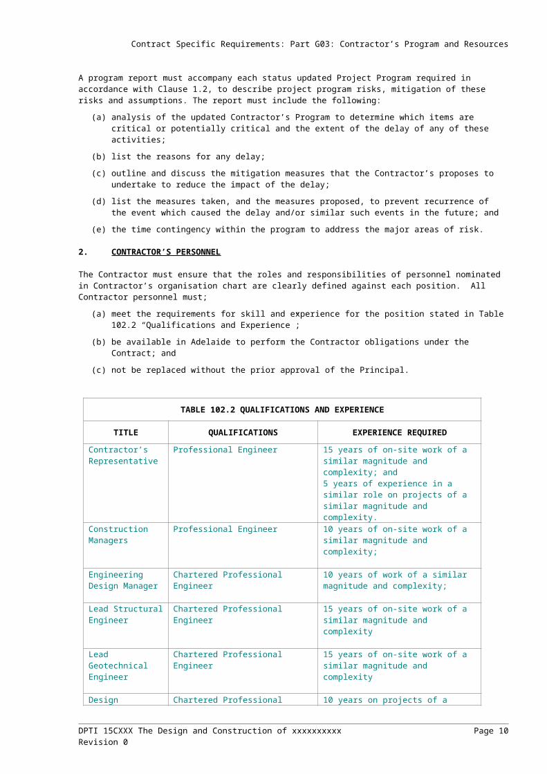
2. CONTRACTOR’S PERSONNEL
The Contractor must ensure that the roles and responsibilities of personnel nominated in Contractor’s organisation chart are clearly defined against each position. All Contractor personnel must;
(a) meet the requirements for skill and experience for the position stated in Table 102.2 “Qualifications and Experience”;
(b) be available in Adelaide to perform the Contractor obligations under the Contract; and
(c) not be replaced without the prior approval of the Principal.
TABLE 102.2 QUALIFICATIONS AND EXPERIENCE
TITLE QUALIFICATIONS EXPERIENCE REQUIRED
Contractor’s Representative
Professional Engineer 15 years of on-site work of a similar magnitude and complexity; and5 years of experience in a similar role on projects of a similar magnitude and complexity.
Construction Managers
Professional Engineer 10 years of on-site work of a similar magnitude and complexity;
DPTI 15CXXX The Design and Construction of xxxxxxxxxx Page 7Revision 0
Contract Specific Requirements: Part G03: Contractor’s Program and Resources
TABLE 102.2 QUALIFICATIONS AND EXPERIENCE
TITLE QUALIFICATIONS EXPERIENCE REQUIRED
Engineering Design Manager
Chartered Professional Engineer 10 years of work of a similar magnitude and complexity;
Lead Structural Engineer
Chartered Professional Engineer 15 years of on-site work of a similar magnitude and complexity
Lead Geotechnical Engineer
Chartered Professional Engineer 15 years of on-site work of a similar magnitude and complexity
Design Verifiers Chartered Professional Engineer 10 years on projects of a similar complexity
Proof Engineers / Independent Design Verifiers
Chartered Professional Engineer 10 years on projects of a similar complexity
Quality Management Representative
Demonstrated understanding of the principles and practices of Quality Management or have completed a course in Quality Management
5 years of on-site work of a similar complexity
Senior Electrical Engineer (HV / LV Power & Lighting)
Professional Electrical Engineer Minimum 5 years of experience in the design, installation, testing and commissioning of; HV and LV Power reticulation and
protection systems Road lighting design
Senior ITS and Control Systems Engineer
Professional Electrical / Control Systems Engineer
Minimum 5 years of experience in the design, installation, testing & commissioning of; ITS Systems Thorough understanding of quality
management and safety in design approaches
Safety Management Representative
Demonstrated understanding of the principles and practices of Safety Management
5 years of on-site work on rail projects of a similar complexity.
Environmental Management Representative
Possess a recognised tertiary environmental qualification
5 years recent experience relevant to the position in similar projects
Community Consultation Representative
Demonstrated understanding of the principles and practices of Community Engagement and have completed a relevant tertiary course
5 years of on projects of a similar complexity.
The Urban Designer(s) and Landscape Architect(s) Design and Landscape Design.
Must be eligible for membership of the DPTI Panel Contract for Urban Design
5 years of on projects of a similar complexity.
Site Superintendent 10 years of on projects of a similar complexity; and10 years of experience in a similar role on tunnel projects of a similar magnitude and complexity.
Site Supervisor – Civil & Structural
10 years of on projects of a similar complexity.
Site Supervisor – Electrical
Qualified Electrician 10 years of on projects of a similar complexity; and2 years of experience in a similar role on tunnel projects of a similar magnitude and complexity.
Site Supervisor – Traffic Management
Qualified in Traffic Management 5 years of on projects of a similar complexity.
DPTI 15CXXX The Design and Construction of xxxxxxxxxx Page 8Revision 0

Contract Specific Requirements: Part G03: Contractor’s Program and Resources
TABLE 102.2 QUALIFICATIONS AND EXPERIENCE
TITLE QUALIFICATIONS EXPERIENCE REQUIRED
Independent Safety Assessor
Professional Engineer 15 Years in Systems Engineering.Knowledge and experience in Systems Engineering and the application of Engineering Safety Management / System Safety standards and principles Domain expertise/experience applicable to the design and engineering of tunnel systems.
Document Controller
Refer Part D10, Clause 6.2 Refer Part D10, Clause 6.2
Landscape Construction Contractor
Must be eligible for membership of the DPTI Panel Contract for Landscape Construction
5 years of on projects of a similar complexity.
Road Safety Auditor Refer Part D13, Clause 3 Refer Part D13, Clause 3Surveyor Refer Part CH30, Clause 2 Refer Part CH30, Clause 2
This CSTR includes additional details relating to the resources required to complete various Works and this table should not be considered as comprehensive.
The Principal may instruct the Contractor to remove from the Site, or from any activity associated with the Contract, any person employed in connection with the Contract, who in the reasonable opinion of the Principal, is incompetent, negligent, guilty of misconduct or failing to diligently undertake their duties. The Contractor must within a reasonable timeframe provide replacement personnel with no less qualifications and experience.
DPTI 15CXXX The Design and Construction of xxxxxxxxxx Page 9Revision 0
Contract Specific Requirements: Part G04: Applicable Standards
PART G04 APPLICABLE STANDARDS
Optional Part for railways
___________
DPTI 15CXXX The Design and Construction of xxxxxxxxxx Page 10Revision 0

Contract Specific Requirements: Part G25: Risk Management
PART G25 RISK MANAGEMENT
For example Contract Specific Requirements for relevant Parts in Division G – General, refer to:
Contract Specific Requirements for Division G (.docx)
DPTI 15CXXX The Design and Construction of xxxxxxxxxx Page 11Revision 0

Contract Specific Requirements: Part D10 Design Requirements - General
PART D10 DESIGN REQUIREMENTS – GENERAL
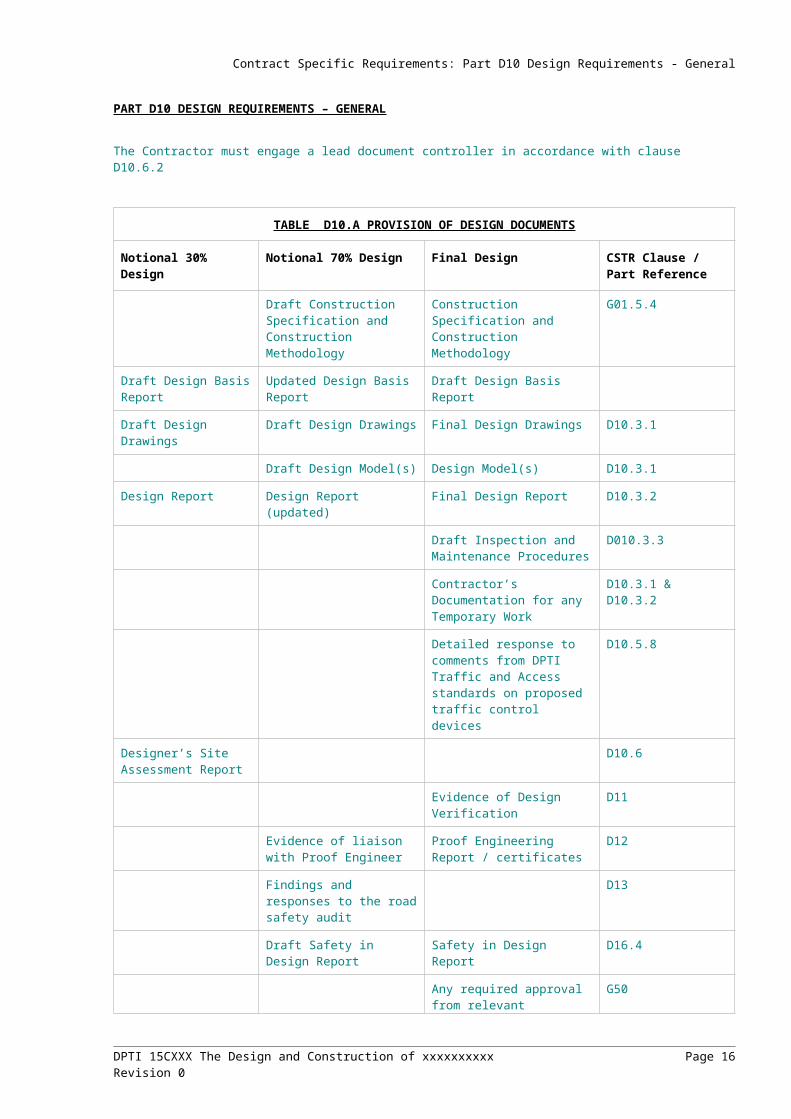
The Contractor must engage a lead document controller in accordance with clause D10.6.2
TABLE D10.A PROVISION OF DESIGN DOCUMENTS
Notional 30% Design Notional 70% Design Final Design CSTR Clause / Part Reference
Draft Construction Specification and Construction Methodology
Construction Specification and Construction Methodology
G01.5.4
Draft Design Basis Report
Updated Design Basis Report
Draft Design Basis Report
Draft Design Drawings Draft Design Drawings Final Design Drawings D10.3.1
Draft Design Model(s) Design Model(s) D10.3.1
Design Report Design Report (updated) Final Design Report D10.3.2
Draft Inspection and Maintenance Procedures
D010.3.3
Contractor’s Documentation for any Temporary Work
D10.3.1 & D10.3.2
Detailed response to comments from DPTI Traffic and Access standards on proposed traffic control devices
D10.5.8
Designer’s Site Assessment Report
D10.6
Evidence of Design Verification
D11
Evidence of liaison with Proof Engineer
Proof Engineering Report / certificates
D12
Findings and responses to the road safety audit
D13
Draft Safety in Design Report
Safety in Design Report D16.4
Any required approval from relevant authorities
G50
Environmental Management Plan (if initial EMP has been revised)
Environmental Management Plan (if initial EMP has been revised)
G50 / D20
Draft Durability Report Durability Report D35.6
Road design visualisation, including a sight distance check and “drive through” of all through vehicular lanes and major turning movement at the drivers eye level
Fully rendered and detailed road design visualisation, including a sight distance check and “drive through” of all vehicular lanes and all turning movement at the drivers eye level
D21
Representation of the urban design elements, by
Representation of the urban design elements, by
D37
DPTI 15CXXX The Design and Construction of xxxxxxxxxx Page 12Revision 0
Contract Specific Requirements: Part D10 Design Requirements - General
TABLE D10.A PROVISION OF DESIGN DOCUMENTS
visualisation and preliminary drawings
visualisation and drawings
DPTI 15CXXX The Design and Construction of xxxxxxxxxx Page 13Revision 0

Contract Specific Requirements: Part D10 Design Requirements - General
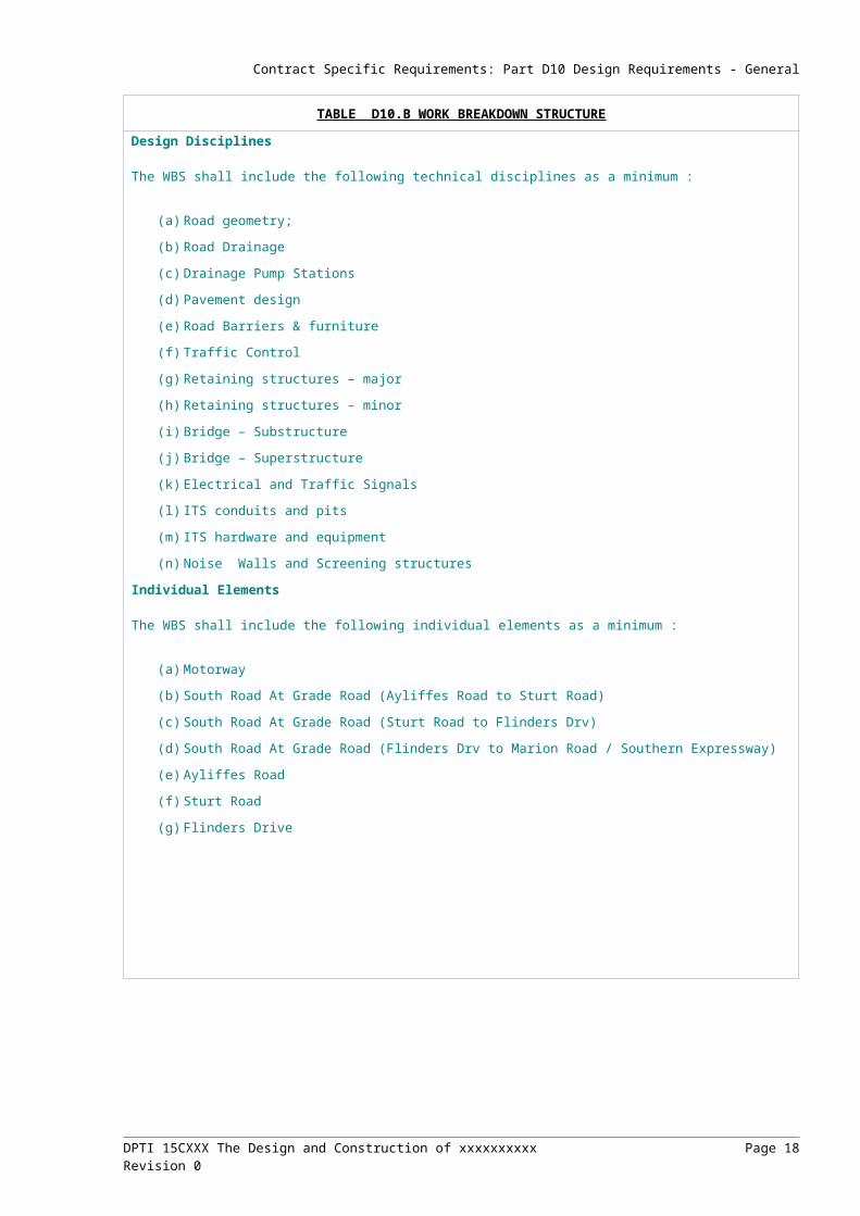
TABLE D10.B WORK BREAKDOWN STRUCTURE
Design Disciplines
The WBS shall include the following technical disciplines as a minimum :
(a) Road geometry;
(b) Road Drainage
(c) Drainage Pump Stations
(d) Pavement design
(e) Road Barriers & furniture
(f) Traffic Control
(g) Retaining structures – major
(h) Retaining structures – minor
(i) Bridge – Substructure
(j) Bridge – Superstructure
(k) Electrical and Traffic Signals
(l) ITS conduits and pits
(m) ITS hardware and equipment
(n) Noise Walls and Screening structures
Individual Elements
The WBS shall include the following individual elements as a minimum :
(a) Motorway
(b) South Road At Grade Road (Ayliffes Road to Sturt Road)
(c) South Road At Grade Road (Sturt Road to Flinders Drv)
(d) South Road At Grade Road (Flinders Drv to Marion Road / Southern Expressway)
(e) Ayliffes Road
(f) Sturt Road
(g) Flinders Drive
DPTI 15CXXX The Design and Construction of xxxxxxxxxx Page 14Revision 0

Contract Specific Requirements: Part D10 Design Requirements - General
ATTACHMENT D10.C
CERTIFICATE OF COMPLIANCE - CONTRACTOR
CONTRACT …………………………………………………………………..
CONTRACTOR ……………………………………………………………….
DESIGN PACKAGE …………………………………………………………..
In accordance with Part D10 of the Contract entered into between the Principal and the Contractor, the Contractor certifies that the Design Documents:
1) comply with the CSTR; and
2) comply with any applicable statutory requirements.
Design Documents:Document Number Revision Document Title
Conditions of Certification:*
* note: written approval from the Principal’s representative of any conditions to certification shall be submitted with the Certificate
Contractors Representative (NPER or CP Eng)
Name: Qualifications
Position:Signed:
Date:
DPTI 15CXXX The Design and Construction of xxxxxxxxxx Page 15Revision 0
Contract Specific Requirements: Part D10 Design Requirements - General
ATTACHMENT D10.C
CERTIFICATE OF COMPLIANCE - DESIGNER
CONTRACT …………………………………………………………………..
CONTRACTOR ……………………………………………………………….
DESIGN PACKAGE …………………………………………………………..
DESIGNER …………………………………………………………………….
In accordance with the requirements of Part D10 of the Contract entered into between the Contractor and the Principal, the undersigned certifies that:
1) the Design Documents comply with the CSTR and any applicable statutory requirements); and
2) the Design Verification and Quality Assurance review has been completed in accordance with the CSTR.
Design Documents:Document Number Revision Document Title
Conditions of Certification:*
* note: written approval from the Principal’s representative of any conditions to certification shall be submitted with the Certificate
Designer’s Representative (NPER or CP Eng)
Name: Qualifications
Position:Signed:
Date:
DPTI 15CXXX The Design and Construction of xxxxxxxxxx Page 16Revision 0

Contract Specific Requirements: Part D11 Design Management - Rail Infrastructure
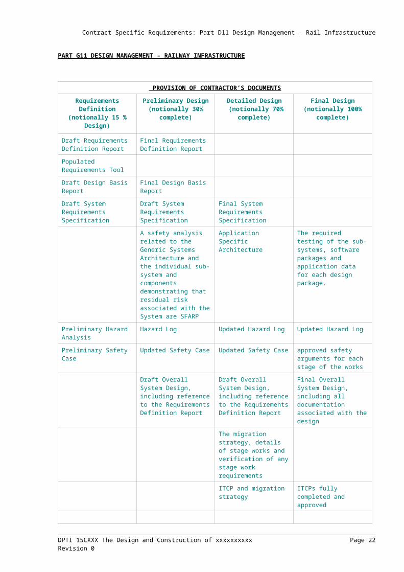
PART G11 DESIGN MANAGEMENT – RAILWAY INFRASTRUCTURE
PROVISION OF CONTRACTOR’S DOCUMENTS
Requirements Definition(notionally 15 % Design)
Preliminary Design (notionally 30%
complete)
Detailed Design (notionally 70%
complete)
Final Design(notionally 100%
complete)
Draft Requirements Definition Report
Final Requirements Definition Report
Populated Requirements Tool
Draft Design Basis Report Final Design Basis Report
Draft System Requirements Specification
Draft System Requirements Specification
Final System Requirements Specification
A safety analysis related to the Generic Systems Architecture and the individual sub-system and components demonstrating that residual risk associated with the System are SFARP
Application Specific Architecture
The required testing of the sub-systems, software packages and application data for each design package.
Preliminary Hazard Analysis
Hazard Log Updated Hazard Log Updated Hazard Log
Preliminary Safety Case Updated Safety Case Updated Safety Case approved safety arguments for each stage of the works
Draft Overall System Design, including reference to the Requirements Definition Report
Draft Overall System Design, including reference to the Requirements Definition Report
Final Overall System Design, including all documentation associated with the design
The migration strategy, details of stage works and verification of any stage work requirements
ITCP and migration strategy
ITCPs fully completed and approved
__________
DPTI 15CXXX The Design and Construction of xxxxxxxxxx Page 17Revision 0
Contract Specific Requirements: Part D12 Independent Design Verification
PART D12: INDEPENDENT DESIGN VERIFICATION
At a minimum:(a) for the elements specified below, design Verification must be undertaken to confirm that the design complies
with the Contract; and(b) Independent Design Analysis must be undertaken where specified.
1) Safety in Design
Consideration in the design of the safety of all persons:
a) during construction of the Works;
b) accessing, operating or utilising the completed Works; and
c) maintaining the Works.
2) Risk Management
Adequacy of the Contractor’s Risk Management Plan
3) Maintenance and Whole of life considerations
For the purpose of this clause only:
“Major Temporary Works” means any temporary works that would have serious consequences (such as a risk to the safety of any person, a delay to work on the critical path or a compromise to the quality of the Works) in the event of the failure of the temporary works to perform as intended.
“Structures” includes bridgeworks, major service / drainage structures, overhead gantries, retaining walls greater than 1.0 m high and non-standard traffic barriers.
a) Design assumptions, parameters and techniques;
b) Independent Design Analysis of to ensure that the strength, stability, serviceability and other requirements defined in the Project Scope and Technical Requirements including:
i) Structures as a whole;
ii) Individual structural elements;
iii) Major Temporary Works; and
iv) Demolition (where applicable);
c) Accuracy of drawings, reports and specifications including:
i) Critical detailing and geometry;
ii) Specifications for materials;
iii) Proposed erection procedures;
iv) Falsework, particularly regarding lateral stability; and
v) Any temporary work or demolition work;
d) The structure achieves the specified durability requirements.
e) Constructability
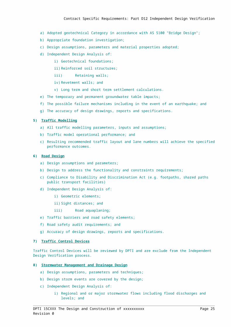
4) Geotechnical Matters
a) Adopted geotechnical Category in accordance with AS 5100 "Bridge Design";
b) Appropriate foundation investigation;
c) Design assumptions, parameters and material properties adopted;
d) Independent Design Analysis of:
i) Geotechnical foundations;
ii) Reinforced soil structures;
iii) Retaining walls;
DPTI 15CXXX The Design and Construction of xxxxxxxxxx Page 18Revision 0

Contract Specific Requirements: Part D12 Independent Design Verification
iv) Revetment walls; and
v) Long term and short term settlement calculations.
e) The temporary and permanent groundwater table impacts;
f) The possible failure mechanisms including in the event of an earthquake; and
g) The accuracy of design drawings, reports and specifications.
5) Traffic Modelling
a) All traffic modelling parameters, inputs and assumptions;
b) Traffic model operational performance; and
c) Resulting recommended traffic layout and lane numbers will achieve the specified performance outcomes.
6) Road Design
a) Design assumptions and parameters;
b) Design to address the functionality and constraints requirements;
c) Compliance to Disability and Discrimination Act (e.g. footpaths, shared paths public transport facilities)
d) Independent Design Analysis of:
i) Geometric elements;
ii) Sight distances; and
iii) Road aquaplaning;
e) Traffic barriers and road safety elements;
f) Road safety audit requirements; and
g) Accuracy of design drawings, reports and specifications.
7) Traffic Control Devices
Traffic Control Devices will be reviewed by DPTI and are exclude from the Independent Design Verification process.
8) Stormwater Management and Drainage Design
a) Design assumptions, parameters and techniques;
b) Design storm events are covered by the design;
c) Independent Design Analysis of:
i) Regional and or major stormwater flows including flood discharges and levels; and
ii) Any pumped drainage system;
iii) The road drainage system including design assumptions parameters techniques; and
iv) The accuracy of design drawings, reports and specifications.
9) Pavements
a) Design assumptions, parameters and methodology, including:
i) Asphalt moduli and fatigue constants; and
ii) Concrete material properties and design philosophy;
b) Geotechnical issues which may affect pavement performance; and
c) Independent Design Analysis of pavement designs;
d) Maintenance strategies and while of life analysis; and
e) Accuracy of design drawings, reports and specifications.
10) Lighting Design
a) Design assumptions, parameters and techniques;
b) Lighting design including:
DPTI 15CXXX The Design and Construction of xxxxxxxxxx Page 19Revision 0

Contract Specific Requirements: Part D12 Independent Design Verification
i) Light luminance (lux levels);
ii) Lighting wiring compliance to electrical regulations; and
iii) Switchboards and conduct design;
c) Independent Design Analysis of the electrical design;
d) Compliance with Office of the Technical Regulator’s requirements,
e) Confirm maintenance in design requirements; and
f) Ensure the accuracy of design drawings, reports and specifications.
11) Electrical, Control and ITS Systems
a) Design assumptions, parameters and techniques;
b) Design to meet the specified functional requirements;
c) Independent Design Analysis of the electrical design, including:
i) Power distribution systems and power protection system;
ii) LV discrimination and fault study; and
iii) UPS sizing;
d) Compliance with Office of the Technical Regulator’s requirements;
e) Safety Integrity Level (SIL);
f) Communications systems including integration with the Principal’s existing communications network;
g) ITS equipment and infrastructure including and suitability and integration with the Principal’s systems;
h) Proposed testing and commissioning;
i) Handover documents and warranties; and
j) Accuracy of design drawings, reports and specifications.
k) Noise Modelling and Mitigation
l) Independent Design Verification of the noise modelling and mitigation as a minimum, must confirm compliance of:
m) Design assumptions, parameters and techniques;
n) Model outputs and reporting; and
o) Noise mitigation methods including treatment types, extents, and materials.
12) Utility Services
Relevant Utility Service Authority’s requirements.
13) Landscape and Urban Design
Specified landscape and urban design requirements.
14) Railway Track Design
15) Rail Signalling Design
16) Railway Electrification Design
_______________________
DPTI 15CXXX The Design and Construction of xxxxxxxxxx Page 20Revision 0

Contract Specific Requirements: Part D13 Road Safety Audit
Specify if a minimum number of auditors is required
Specify the stages that the road safety audits msut be undertaken at – eg:
The Contractor must ensure that Road Safety Audits are conducted at the following stages:
(a) Feasibility Design where appropriate;
(b) Completion of design development;
(c) Completion of Final Design;
(d) During construction, where temporary traffic management measures are proposed;
(e) 2 weeks prior to opening to traffic; and
(f) within 1 week of opening to traffic.
DPTI 15CXXX The Design and Construction of xxxxxxxxxx Page 21Revision 0
Contract Specific Requirements: Part D19 Design - Environmental
PART D19 DESIGN - ENVIRONMENTAL
The Principal has /will obtain the following environmental authorisations:
(a) Significant Tree removal approvals under the Development Act 1993 for those trees identified as such on drawing no xxxxx:
Examples:
1.1 Noise Assessment Modelling
The Principal has undertaken noise modelling to determine the impact of traffic noise, which is included in Appendix D020.9. This modelling identified the need to mitigate the traffic noise from xxxx.ORThe assessment for road traffic noise must be undertaken in line with the process described in Section 5 of the RTNG. In the event of any conflicts or ambiguities, clarification must be sought from the Principal prior to proceeding.
The modelling and design of the noise treatment must be undertaken by an appropriately qualified acoustic Environmental Specialist.
The model and report must be submitted with the Preliminary and Final design documentation.
The Contractor must undertake an on site assessment and testing of existing (pre-construction) traffic noise levels for potential sensitive receivers and locations.
The Contractor must undertake all noise assessment and modelling to determine, detail and optimise any noise treatments required across the project required to mitigate noise generated from the Works to the levels detailed in the RTNG.
Treatment to buildings must not be used as a noise abatement measure, unless approved in writing by the Principal’s Authorised Person.
1.2 Noise Mitigation and Implementation Plan
A Noise Mitigation and Implementation Plan (NMIP) must be prepared by the Contractor that identifies all assumptions, monitoring and modelling results (including noise barrier height, start chainage, end chainage, total length, predicted noise reductions, material to be constructed with, etc).
The Design of any noise treatments must be in accordance with the RTNG and Part D037.
The Contractor must:
(a) include a Scope of Works Document as part of the NMIP for each property eligible to receive a Facade Treatment Package, including:
(i) a sketch plan detailing building orientation, room use and applicable treatment package;
(ii) scope of noise mitigation treatments to be offered;
(iii) information regarding fixtures identified for treatments (measurements, photographs, observations regarding practical implications for installation);
(iv) photographs of pre-existing conditions and work area; and
(v) a cost estimate.
(b) ensure that when designing mitigation treatments, consideration must be given to the existing property features to ensure that (where reasonable and practical) proposed treatments conform to the existing style and character;
(c) undertake discussions and negotiations with the property owners to finalise the Scope of Works and agree on details such as finishes and make good provisions;
(d) ensure that the final design generating the Scope of Works for each property will meet the requirements of the approved Noise Modelling and Mitigation Design Report and the Building Code of Australia when the treatments are installed; and
DPTI 15CXXX The Design and Construction of xxxxxxxxxx Page 22Revision 0

Contract Specific Requirements: Part D19 Design - Environmental
(e) obtain formal property owner agreement on the final treatment measures to be installed including barriers, architectural treatments and any reinstatement works as required. The property owner must be provided with an Agreement to sign. The Agreement must consist of:
(i) details of the agreed Scope of Works; and
(ii) authority to access the property and undertake works.
Provision of the Noise Mitigation and Implementation Plan shall constitute a HOLD POINT.
1.3 Façade Treatments
The DPTI - Property Noise Mitigation – Façade Treatment Package Specification is provided in Appendix A5. All Façade Treatments installed must comply with the Specification. The Specification must supplement the Scope of Works documents and provides further information regarding:
(a) reference to acoustic performance and specification requirements and suitable proprietary products;
(b) typical construction drawing details; and
(c) construction notes regarding practical implications for installation.
The Contractor must not undertake property works until the Agreement has been signed by the property owner and approval provided by the Principal. Where the property has a tenant an access agreement must be obtained prior to undertaking works on the property.
Where noise mitigation treatments are to be installed, construction inspections (as required) must be undertaken to ensure that the works are proceeding as per the design and Scope of Work. On completion, the Contractor must undertake an inspection of the works and provide a signed Completion of Works certificate when the works have been accepted as complete and co-signed by the property owner(s).
The Contractor’s builder must provide a Certificate of Compliance with the Building Code of Australia for all works undertaken. The builder must be appropriately qualified to issue the Certificate of Compliance in accordance with the Australian Building Code.
A warranty period of two (2) years must apply from the date of co-signing of the Completion of Works certificate by the property owner for all property façade treatments.
The Completion of Works certificates and Certificates of Compliance must be provided to the Principal within two weeks of being signed.
A representative of the Principal must be invited to attend all engagement meetings/activities with Property owners/tenants. A minimum of 48 hours notice must be provided to the Principal.
1.4 Property Assessments
Where noise mitigation treatments are to be installed at private properties, the Contractor must undertake property inspections and consultation with the affected landowners to determine the exact nature of the treatments.
Property inspections must include attendance by the following personnel:
(a) Contractor’s Personnel (Project Manager; community engagement representative)
(b) Contractor’s acoustic Engineer,
(c) Contractor’s Architect (for Packages 2,3 and 4 Treatments and as required for Package 1), The Architect must be experienced in acoustic design and installation for residential properties
(d) Quantity Surveyor (as required),
(e) Principals (DPTI) representative must be given the option to attend with at least 48 hours notice.
The inspections must allow for:
(a) informing the property owner about the noise mitigation process;
(b) an inspection of the property by the architect;
(c) an inspection of the property by the acoustic engineer; and
(d) input from the property owner on any preferred treatments.
Additional meeting(s) with the property owner may also be required.
DPTI 15CXXX The Design and Construction of xxxxxxxxxx Page 23Revision 0

Contract Specific Requirements: Part D19 Design - Environmental
1.5 Verification
At Practical Completion and 12 months following Practical Completion the Contractor must undertake post-construction noise monitoring and modelling once all of the roads are fully operational to verify that the operational road traffic noise complies with the RTNG.
Following Completion and the operation of road at ultimate speeds, the Contractor must undertake post construction noise measurements in conjunction with traffic counters at or as near as possible to previously monitored locations, as agreed with the Principal’s Authorised Person, for a minimum of 5 week days. Adjustments must be made for traffic flow rates and likely road surface noise corrections at the time of monitoring.
Noise monitoring must be undertaken in accordance with relevant Australian Standards and EPA requirements.
The Contractor is responsible for rectifying the implemented noise treatments if the monitoring and verification modelling results do not comply with the RTNG at all sensitive receivers.
1.6 Vibration
The Contractor must demonstrate the consideration of the construction methodology and the potential vibration impacts and provide the details as required in the Construction Noise and Vibration Management Plan as detailed in the Part 7 Environmental Management requirements and Part CH50 Environmental Protection Issues.
Determination of the vibration impacts as a result of the design must be assessed by an appropriately qualified Environmental Specialist.
1. AIR QUALITY
The Principal has undertaken air quality modelling and is included in the appendices. Additional modelling must be undertaken to:
(1) Estimate existing air quality relevant to the study area for baseline purposes to enable an assessment of changes from the project.
(2) Obtain the Principal’s approval for the computer models to be used by the Contractor.
(3) Validate calibration of the model using local conditions.
(4) Assess the impact on local and regional air quality, and compare predicted levels with current air quality objectives.
(5) Model the potential impacts for both the construction and operation of the road.
(6) Establish air quality mitigation and management requirements for operation and construction (e.g. management of dust generation) for inclusion in the draft CEMP.
13.1 Acid Sulphate Soils
The Contractor must design and construct the works so as to not cause environmental harm or detriment to the environment. Management of risks associated with the exposure of actual or potential acid sulphate soils and mono-sulfidic black ooze must be incorporated into the design. Reference must be given to DPTI’s ASS Guideline for Assessment and Management, the EPA’s Site Contamination – acid sulphate soil materials guideline, and where relevant current guidelines being undertaken by CSIRO Land and Water.
4. ENVIRONMENTAL AND SUSTAINABILITY OBJECTIVES
Subject to the requirements of this CSTR, the Contractor’s design and construction methodology must be undertaken to maximise the achievement of the following objectives (the Infrastructure Sustainability (IS) Rating Scheme v1.2 credits that either wholly or partially align with the objectives are shown in brackets):
(a) provide leadership and commitment in environmental management and sustainability (Man-1);
(b) consider sustainability aspects in project decision making (Man-7);
(c) consider environmental, social and economic aspects in the procurement process (Pro-1);
(d) minimise energy consumption to reduce greenhouse gas emissions across the infrastructure lifecycle (Ene-1);
(e) apply the principles of water conservation across the project’s lifecycle (Wat-1);
DPTI 15CXXX The Design and Construction of xxxxxxxxxx Page 24Revision 0
Contract Specific Requirements: Part D19 Design - Environmental
(f) minimise greenhouse gas emissions associated with the use of materials across the infrastructure lifecycle (including the use of sustainable alternatives where approved by the Principal) (Mat-1; Mat-2);
(g) provide protection of water quality through incorporation of Water Sensitive Urban Design (WSUD) and Water Sensitive Road Design (WSRD) elements and prevent pollution of surface, ground and marine waters (Dis-1);
(h) provide protection of noise sensitive receivers from road traffic noise through incorporation of appropriate mitigation measures (Dis-2);
(i) minimise the effect of vibration on sensitive structures and sensitive receivers (Dis-3);
(j) minimise air quality impacts (Dis-4);
(k) avoid mobilisation of contaminants and where feasible undertake remediation of contaminated land on the Site (Lan-3);
(l) apply the principles of the waste hierarchy (avoid, reduce, reuse, recycle and recover) to maximise diversion of waste from landfill (Was-1; Was-2);
(m) minimise the destruction and disturbance of regulated and regulated significant trees as well as other amenity vegetation (Eco-1);
(n) maintain and preserve existing areas of vegetation and protect fauna habitat (Eco-1; Eco-2);
(o) enhance the amenity of the road corridor and surrounding areas with urban design and landscaping (Eco-1Urb-1; Urb-2);
(p) prevent disturbance to known Aboriginal Heritage sites (Her-1; Her-2);
(q) protect and conserve non-Aboriginal cultural heritage sites (Her-1; Her-2);
(r) implement a community engagement strategy that proactively engages key stakeholders and the local community about the project and monitor their acceptance (Hea-1; Sta-1; Sta-2; Sta-3; Sta-4);
(s) provide a quality urban design outcome that achieves a high standard of environmental sustainability (Hea-2; Urb-1; Urb-2);
(t) as a minimum, no net loss of shorebird habitat, wetlands, mangrove forest and salt marsh; and
(u) ensure compliance with environmental legislation, regulations and approvals.
2. SUSTAINABILITY
The Contractor must register the project with the Infrastructure Sustainability Council of Australia (ISCA) and achieve a certified Design Rating and As Built Rating under the Infrastructure Sustainability (IS) rating scheme within 40 days of entering into the Contract. The Principal must be invited to attend and participate in any sustainability related workshops/meetings during the process. 15.1 ISCA Sustainability Minimum Rating The Contractor must achieve a certified Design Rating and a certified As Built Rating under the IS rating scheme version 1.2 of “Excellent’ (i.e. rating score of 50) or greater.
A minimum Level 1 must be achieved for all Credits, unless otherwise scoped out (as verified through ISCA) or appropriate justification provided as to why Level 1 is unable to be achieved on the Project and approved by the Principal.
15.2 Sustainability Management Plan
The Contractor must develop a Sustainability Management Plan. It must, as a minimum:
(a) provide a commitment/policy to achieving sustainability outcomes on the project;
(b) demonstrate how the sustainability objectives provided in Clause 4 of this Part will or have been implemented, including providing the processes which will be applied to implementing the objectives;
(c) provide qualitative and quantitative targets to demonstrate the implementation of the sustainability objectives;
(d) demonstrate how each of the Categories and Credits of the IS Rating Scheme will be considered and implemented;
(e) include an initial self-assessed IS rating tool scorecard;
(f) track the costs and benefits associated with the use and implementation of the IS rating tool; and
DPTI 15CXXX The Design and Construction of xxxxxxxxxx Page 25Revision 0

Contract Specific Requirements: Part D19 Design - Environmental
(g) track the costs and benefits associated with project specific sustainability initiatives (including reductions in CO2e tones, diversion from landfill, community acceptance and whole of life benefits/costs).
The Sustainability Management Plan must be in accordance with the ISCA Infrastructure Sustainability Rating Management Plan template (Appendix A5).
The Sustainability Management Plan must be submitted to the Principal and constitutes a HOLD POINT. It must be updated on a six monthly basis throughout the design and construction phase and provided to the Principal and ISCA whenever it is updated.
15.3 IS Rating Tool
The IS rating tool scorecard must be completed in accordance with the requirements of the IS rating tool: Technical Manual. A completed IS rating tool scorecard and supporting evidence must be prepared and submitted for verification and certification through ISCA by notional 100% design stage or as otherwise agreed with the Principal to achieve the Design rating. Subject to consultation with ISCA, the design rating certification must be obtained within three months of submission to ISCA.
The IS rating tool scorecard and all supporting evidence associated with the verification and certification process to achieve a Design rating must be provided to the Principal within the above timeframes.
The IS rating tool scorecard and IS Technical Manual is available on the ISCA website http://www.isca.org.au/ and general questions about the IS rating scheme can be referred to ISCA.
Where the Principal has provided information that can be used as supporting evidence to contribute to achieving various credits (full or partial) within the IS rating scheme these are provided in Appendix XX. Refer to Contract Specific Part CH50 for further details on the requirements for achieving the As Built Rating.
DPTI 15CXXX The Design and Construction of xxxxxxxxxx Page 26Revision 0
Contract Specific Requirements: Part D20 Design – Road Infrastructure
PART G20 DESIGN – ROAD INFRASTRUCTURE
ROAD GEOMETRY
1. Design Environment
The Works are deemed to be located in an urban/rural environment.
2. Traffic Volumes
DESIGN TRAFFIC VOLUMES
Location Annual Average Daily Traffic
% Commercial Vehicles
Design Hourly Volume
Minimum Operating Speed
(km/h)e.g. Main Carriageway or Road Name
Or refer to an appendix in lieu of the above table.
3. Traffic Volume Lane Distribution
Insert any contract specific requirements here
eg
(a) provision for bus movements including longer buses and/or movement to and from bus bays;
(b) the level of access for restricted access vehicles such as the longer articulated vehicles like B-Doubles/Triples;
(c) special provision for turning vehicles stating the location and requirements, or specific local traffic management issues which might preclude access to certain areas;
(d) special or additional lane width or clearance requirements, e.g. for local streets.
Car park and Kiss and Ride Accesses Passenger car
Access to Interchange (from South Road, Sturt Road and Southern Expressway
12.5 m rigid bus/19.0 m articulated bus
Internal road (bus only) network 12.5 m rigid bus/19.0 m articulated bus
Internal road network – other 8.8 m service vehicle
New Science Park Access Road 12.5 m single unit truck
Birch Crescent Realignment 8.8 m service vehicle
Flinders Drive/South Road/Interchange Access Intersection
12.5 m rigid bus/19.0 m articulated bus plus 12.5 m single unit truck and passenger car
Flinders Drive/Flinders Private Hospital Access Road junction
12.5 m single unit truck
4. Design Speed
eg
Element Design Speed (km/h)
Elevated Roadway 100South Road Superway Main Alignment (Regency Road to the southern end of the Elevated Roadway) 90
Elevated Roadway ramps – Grand Junction Road 80
DPTI 15CXXX The Design and Construction of xxxxxxxxxx Page 27Revision 0

Contract Specific Requirements: Part D20 Design – Road Infrastructure
Element Design Speed (km/h)
Elevated Roadway ramps – connection to the Port River Expressway and Salisbury Hwy 80
South Road At-Grade roads (local access roads) 70
Northern Connector (main alignment, north of the Port River Expressway ramp gore area) 120Northern Connector (ramps from / to the Port River Expressway to the Northern Connector gore area) 100
Port River Expressway / Salisbury Highway east-west connection 90
Local Council maintained roadways 60
DPTI Arterial Roads 70
The design speed of loop ramps associated with the Northern Connector interchange may be reduced in accordance with Austroads Guide to Road Design Part 4C Interchanges, clause 6. Adoption of lower design speeds for interchange ramps must incorporate adequate speed change arrangements to provide for transitions from highway speeds to ramp speeds.
5. Geometric Design
South Road Superway Main Alignment
The South Road Superway Main Alignment must provide a motorway standard roadway from the Elevated Roadway to Regency Road must provide for the specified design vehicle, capacity and connectivity.
Median openings on the at-grade section of South Road Superway Main Alignment between Aruma Street and Regency Road must all be closed to maintain a free flow non-stop corridor
South Road At-Grade
The South Road At-Grade must provide to provide a local access roadway for local or regional access under and/or adjacent to the Elevated Roadway for the specified design vehicle, capacity and connectivity.
Intersections with Council Maintained Roads
Intersections must be provided with the following features and connectivity:
(a) Wing street – provide east west connectivity, and all movements from both the one way southbound local access road from Salisbury Highway and two way local access road from South Terrace;
(b) York Street – a new T intersection to provide for all movements is desirable;
(c) Leed Street – a new T intersection to provide for all movements except left-out is desirable;
(d) South Terrace - provide a signalised intersection to provide for all movements except for right-turn in from South Road At-Grade. Signals to be coordinated with the Wingfield railway crossing;
The design must comply with the minimum clearance/cover required by the owners of all overhead and/or underground utility services affected by the Works.
6. Design Level of Service
egLevel of Service assessment must be undertaken on the roadway to determine the future congestion of the roadway in accordance with Austroads Road Design Guide, Guide to Traffic Management Part 2.
Level of Service and traffic modelling assessments must be completed for all intersections to determine the future congestion and performance of intersections in accordance with Austroads Road Design Guide, Guide to Traffic Management Part 3.
The minimum Design Level of Service is detailed in the table below.
DPTI 15CXXX The Design and Construction of xxxxxxxxxx Page 28Revision 0
Contract Specific Requirements: Part D20 Design – Road Infrastructure
Location Minimum Level of Service Traffic Volumes
Elevated Roadway D 2031
South Road Superway Main Alignment (Regency Road to the Elevated Roadway) D 2031
Interchange with Port River Expressway / Salisbury Highway D 2031
Future Northern Connector interchange D 2031
DPTI arterial roads E 2031
South Road At-Grade (local access roads beneath the Elevated Roadway) E 2031
All signalised intersections E 2031
The Contractor must demonstrate the Level of Service that can be achieved for all roadways and intersections and demonstrate measures to further maximise Level of Service, such as ramp metering, ITS technology.
Where the design level of service specified cannot be achieved on all intersection movements within the road reserve and land and property acquisition provided the Contractor must:
(a) maximise the intersection design within the existing road reserve and land acquisition boundary;
(b) maximise the level of service of the major traffic movements;
(c) demonstrate the average level of service provided at the intersection; and
(d) demonstrate measures to further maximise Level of Service, such as ramp metering, ITS technology.
7. Sight Distance
(a) any height controls that may affect sight distance at particular locations:
8. Vertical Clearances To Bridges/Structures
(a) minimum design clearances for bridges over certain road classes;
(b) design clearances required for navigable waterways;
(c) design clearances required for tramway routes:
9. Design Vehicle
The design of all roads must allow for the design vehicle, including accommodation of vehicle swept paths, for all through lanes, turning and deceleration lanes and intersections.
The free flow carriageways must be designed in accordance with Level 3 access (i.e. B-Triple and A-Double (Double Road Train)) requirements of the National Transport Council Performance Based Standards Scheme Network Classification Guidelines.
The design must make allowance for over-dimensional / over-mass vehicles as per DPTI Over Dimensional Route Network as detailed in Appendix D021.3 DPTI Heavy Vehicle Access Framework
Design vehicles must be as shown in the table below:
Location Design Vehicle
Elevated Roadway from Port River Expressway / Salisbury Highway to the Grand Junction Road Interchange A Double & B Triple
Elevated Roadway and Main Alignment south of the Grand Junction Road Interchange B Double
Elevated Roadway ramps at Grand Junction Road and Port River Expressway / Salisbury Highway
A Double & B Triple all movements
DPTI 15CXXX The Design and Construction of xxxxxxxxxx Page 29Revision 0
Contract Specific Requirements: Part D20 Design – Road Infrastructure
Location Design Vehicle
Taminga Street / South Road At-Grade Intersection A Double & B Triple left inB Double left out
Aruma Street / South Road At-Grade Intersection A Double & B Triple left inB Double left out
Camira Street / South Road Superway Main Alignment intersection A Double & B Triple left inB Double left out
Tikilara Street / South Road Superway Main Alignment intersection A Double & B Triple left inB Double left out
Regency Road / South Road Superway Main Alignment intersection B Double all movements
All existing road access, including access for over dimensional vehicles to properties along the South Road Corridor must be maintained. Any alterations to current access arrangement are to be approved by the Principal.
The Contractor must provide any additional drawings or modelling to demonstrate the road design can accommodate the design vehicle.
The A-Double, B-Double and Semi Trailer (heavy articulated) design vehicle must be in accordance with DPTI heavy vehicle access framework Appendix D021.3.
The B-Triple design vehicle must be in accordance with the National Transport Council Blueprint B-Triple Specification that is deemed to satisfy level 3 Performance based specification requirements with an overall maximum length of 34.29m.
The design vehicles adopted for double right turns must provide for simultaneous movements of the Design Vehicle and a 8.8m service vehicle, with the service vehicle in the median lane.
The design of left turns at unsignalised intersections may allow the Design Vehicle to enter the adjacent lane, where it can be demonstrated that:
(a) the manoeuvre is a legal movement for the Design Vehicle;
(b) current access conditions are maintained; and
(c) reduces or results in no additional property acquisition.
10. Traffic Lanes and Widths
The Contractor must undertake traffic modelling to determine the number, configurations and length of traffic lanes to the meet the level of service requirements specified In addition the number of traffic lanes provided must meet the minimum requirements as detailed in the following tables. Traffic modelling must be based on the volumes specified in Appending D021.2.
Lane and shoulder widths are to be in accordance with Austroads Road Design Guide or the AS 5100 "Bridge Design" as applicable. Notwithstanding the above, all shoulder widths must provide for road design requirements and in particular horizontal sight distances, including for future expansion to the specified number of lanes.
The minimum number of traffic lanes on the Elevated Roadway and South Road Superway main alignment must be as shown in the table below:
Main Alignment & Elevated Roadway Minimum Number of Traffic Lanes
Ramp from the Elevated Roadway to the Salisbury Highway Two lanes
Ramp from the Elevated Roadway to the Port River Expressway One lane
Rampfrom the Salisbury Highway to the Elevated Roadway Two lanes
Ramp from the Port River Expressway to the Elevated Roadway One Lane
Port River Expressway / Salisbury Highway to Grand Junction Road Interchange
Three lanes with provision for future expansion to four lanes in each direction.
11. Weaving Analysis
DPTI 15CXXX The Design and Construction of xxxxxxxxxx Page 30Revision 0

Contract Specific Requirements: Part D20 Design – Road Infrastructure
Analysis of Traffic weaving to determine the level of service between interchanges must be undertaken using the DPTI Aimsun Modelling manual as detailed in Appendix D021.5.
Traffic movements for weaving analysis must be determined based on the MASTEM Select Link Model (Weaving) as detailed in appendix D021.6.
1. PEDESTRIAN FACILITIES
Continuous and fully accessible movements for pedestrians must be provided at-grade for the entire length of the Works. Existing pedestrian connectivity must be maintained.
Pedestrian crossing facilities must be provided to connect to the east-west road network at signalised intersections, including provision of pedestrian actuated crossings.
There must be no pedestrian provision along the Elevated Roadway and pedestrian thoroughfares are to be diverted away from Elevated Roadway on / off ramps and approach ramps
All elements of footpaths and pedestrian crossings must allow for disability be in accordance with AS 1428 Design for Access and Mobility, the Austroads Guide to Road Design and DPTI’s Guidelines for Disability Access in the pedestrian environment.
2. CYCLING FACILITIES
Cyclist facilities must be provided to enable connectivity between the Port River Expressway / Salisbury Highway, along the local access roadway and South Road Superway Main Alignment.
Cyclist facilities must be designed to maintain priority and travel speed of cyclist as a road user, including provision for cyclists within the roadway and at intersections. Connections to east-west streets and intersections must be provided to link to the existing and future local area bicycle network.
Cyclists must be prohibited from the Elevated Roadway Structures and cyclist facilities must not be provided along the Elevated Roadway. Measures are to be taken to restrict cyclists from the Elevated Roadway and encourage cyclists to use the local access road and not the Elevated Roadway.
Cyclist facilities must be provided in accordance with the Austroads Guide to Road Design and AS 1742.9 Bicycle Facilities.
3. PUBLIC TRANSPORT FACILITIES
Public Transport Facilities to maintain existing public Transport Facilities must be provided for the entire length of the Superway including indented bus bays and pedestrian shelters and bus stops.
The Contractor must obtain approval from relevant authorities for the location and details of public transport facilities.
4. PROPERTY ACCOMMODATION
Where property driveway crossovers and stormwater drainage connections abut the works, the Contractor must negotiate with the property owners regarding the design of crossovers and drainage connections. The Contractor must invite the Principal to attend these negotiations. These must include consideration of, and agreement to, the type and width of driveway crossover at the property boundary and the method of disposal of property stormwater. The Contractor must verify that the design of the property crossovers does not allow stormwater to flow from the road down a driveway.
5. RAIL REQUIREMENTS
Notwithstanding other specified vertical clearances to the Elevated Roadway a minimum vertical clearance of 7.2m must be provided from the top of rail to the underside of the Elevated Roadway over ARTC Rail corridor to cater for double stacked containers. This allowance is based upon Figure 7.17 “Rolling Stock Outline F” in the Code of Practice for the Defined Interstate Rail Network.
Any permanent and temporary structures of the Elevated Roadway over the ARTC corridor must be in accordance with ARTC requirements and clear zones and allow for future duplication of the rail line.
All piers must be outside the ARTC corridor. Buried works that protrude into the corridor must be subject to approval by the ARTC. The Contractor must be responsible for obtaining approval from the ARTC.
The railway crossing of South Road At-Grade and the Winfield Railway line must be in accordance with ARTC requirements and must provide an active railway crossing integrated with traffic signals, including the signals at South Terrace and Cormack Road.
DPTI 15CXXX The Design and Construction of xxxxxxxxxx Page 31Revision 0

Contract Specific Requirements: Part D20 Design – Road Infrastructure
Where appropriate, the Contractor must liaise with ATRC in accordance with the requirements specified in Part CH75: Track Access - External Rail Transport Operator (available from: http://www.dpti.sa.gov.au/contractor_documents/specifications).
6. FUTURE EXPANSION AND EXTENSION CONSIDERATIONS
The Elevated Roadway design must include allow for future upgrades of North-South Corridor including:
(a) connection with the Northern Connector including the proposed Northern Connector interchange;
(b) accommodate an additional lane in each direction;
(c) accommodate a crossing around the midpoint of the Elevated Roadway near the Grand Junction Road Ramps to allow for emergency vehicle access; and
(d) flexibility to allow for connection to either an on-line or offline scheme for future southern upgrades of the North-South Corridor.
Design of Traffic Signals
Examples:
1. Attachment D32A Traffic volumes and other data
(a) 2014 traffic volumes for base case models and construction model
(b) 2021 design volumes;
(c) 2031 design volumes, (d) origin-destination matrices based on the above volumes are provided in electronic copies of the
Microsimulation models (see Attachment D32C below)
2. Attachment D32B Modelling Software Applications and model requirements
“Individual signal controlled intersection”A separate assessment is to be made using SIDRA of the performance of individual intersections.These intersections shall include the following: list:
1. TS1002. TS1013. TS102, etc.
“Traffic Signal Coordination”
The Contractor must use TRANSYT for the optimisation of traffic signal co-ordination. This modelling must be undertaken in accordance with the DPTI: Traffic Modelling Guidelines – TRANSYT-15 (provided in Appendix 13).
The modelling should extend to cover current link chains and sites that need to be added for the purposes of construction traffic management or due to changes in traffic patterns post completion. The extent of the TRANSYT model(s) must be:
(a) Port Road – from TS3090 Port/Gaol to TS039 Port/Kilkenny;
(b) Grange Road – same model as Port Road as TS152 Adam/Manton links to TS037 Port/Park/Adam and TS051 South/Grange links to TS038 South/Port; and
(c) Torrens Road – from TS035 South Road to TS169 Rosetta Street, and from TS020 Woodville Road to TS022 Regency Road, and from TS021 Torrens/Hanson to TS003 Hanson/First
“Intersection and interchange performance”
The Contractor must use Aimsun Microsimulation to analyse the performance of the network, intersections and interchanges including ramp arrangements amd weaving sections, transit schedules, and level crossing queue relocation measures, during AM and PM peaks for 2021 and 2031.
This Microsimulation modelling must be in accordance with the DPTI AIMSUN Model Development Manual and in the same linear sub-area as the reference design model that has been provided.
DPTI 15CXXX The Design and Construction of xxxxxxxxxx Page 32Revision 0

Contract Specific Requirements: Part D20 Design – Road Infrastructure
The Contractor must demonstrate that the design performs no worse than the reference design in both 2021 and 2031.
The following AIMSUN models are available from DPTI:
“2021 Reference Design Model”
The 2021 microsimulation model includes the reference design within the model area. The Contractor must model network performance in accordance with the performance indicators specified in Clause 8.
“2031 Projected Model”
The 2031 microsimulation model includes the North-South Corridor as being fully implemented. The Contractor must design and document how implementation of the Torrens Road to River Torrens Project scope can be expanded to the full North-South Corridor and cater for 2031 design volumes with minimal redundant work. The Contractor must model network performance in accordance with the performance indicators specified in Clause
3. Attachment D32C Intersections which must be included in the Transport / Traffic Modelling Scope.
From a Mesoscopic AIMSUN model of Adelaide calibrated to a 2014 base case, DPTI has derived, the following linear Aimsun microsimulation models, spanning from the South Road/Regency Road through to South Road/West Thebarton Road/Ashwin Parade, have been developed for use by the Contractor. The model suite includes the following model types
(a) Construction model, based on 2014 traffic volumes
(b) 2021 reference design model
(c) 2031 North-South Corridor model
The following list of road network upgrades have been included in the models and are expected to be implemented prior to the commencement of this project::
(a) South Road/Richmond Road intersection upgrade and Richmond Road widening
(b) James Congdon Drive duplication
(c) Park Terrace/Fitzroy Terrace/Torrens Road widening
(d) South Road/Ashwin Parade/West Thebarton Road intersection upgrade
4. Attachment D32D Hardware requirements identified by Principal.
The following provisions are to be documented in the Design Report and included in the R55 installation of Traffic Signals.UPS to be provided at: TS101, TS102 and TS103.CCTV to be provided at TS 104
STORMWATER
3. ACCIDENTAL SPILL MANAGEMENT
Accidental Spill Management devices are / are not to be provided as part of the Stormwater Design.
4. WATER SENSITIVE ROAD DESIGN (WSRD)
Permanent Water Sensitive Road Design devices are / are not to be provided as part of the Stormwater Design.
EARTHWORKS
1. GENERAL FILL
Unless the Contractor’s design establishes other parameters, at a minimum, General Fill material must comply with the following:
DPTI 15CXXX The Design and Construction of xxxxxxxxxx Page 33Revision 0

Contract Specific Requirements: Part D20 Design – Road Infrastructure
General Fill – Specified Requirements
Material Classification (Refer to CSR
Part R10 and R15 for definitions)
Maximum allowable Weighted
Plasticity Index (WPI)
Shrink Swell Index
Iss (%)
Level of compaction Range of Placement Moisture Content
General Fill 1 (GF1)
3000 1.7 95% (Standard) OMC ± 2%
General Fill 2 (GF2)
unlimited unlimited 95% (Standard) OMC ± 2%
2. DEEMED TO COMPLY DESIGN
Batter Slopes
If Type D Material is not used in the batters, the following slopes are deemed to be a complying earthworks design.If the Contractor proposes to use Type D Material in the batters or steeper batters, the Contractor must prepare a design in accordance with DPTI Design Standard: Earthworks for Roads EW100.
Earthworks Batters
Batter Height Maximum Unsupported Batter slope
Comment / Conditions
Cut and Fill Batters - less than 2m high:
1V:6H Provide a forgiving road environment for errant vehicles at low cost.
Cut and Fill Batters - 2-4 m high:
1V:4H Do not require barriers, are able to be mown.
Cut and Fill Batters - higher than 4m:
1V:3H Are generally not suitable for landscape maintenance machinery access and slashing.
Batters to drains within clear zone
1V:4H1V:6H if slope is within 6 m of edge of pavement1V:3H in constrained locations
Less critical than slopes immediately adjacent the carriageway due to reduced chance of vehicle traverses. Drains can be traversed by vehicles and mown for maintenance purposes
Subgrade
The Contractor is responsible for verifying that any Unsuitable Material below fill or below pavement in cuts is removed or treated so that the earthworks design complies with the requirements of EW100. At a minimum, 600 mm of existing material must be removed under the pavement “footprint” where embankments are to be constructed.
3. SETTLEMENT
Settlement Limitations
Level changes in the finished pavement surface must comply with the following:
(a) no increase in levels after completion of construction of the pavement;
(b) maximum decrease in level of the pavement surface of 30 mm over any 12 month period following the construction of the pavement;
(c) maximum differential settlement of 30 mm in a longitudinal direction, measured between Settlement Measurement Points spaced at 50 m, following construction of the pavement until the Date of Final Completion;
(d) maximum differential settlement of 12 mm in a longitudinal direction, measured between Settlement Measurement Points spaced at 20 m, following construction of the pavement until the Date of Final Completion;
(e) maximum differential settlement of 15 mm in a transverse direction, when measured between Settlement Measurement Points on opposite sides of each carriageway following construction of the pavement until the Date of Final Completion;
DPTI 15CXXX The Design and Construction of xxxxxxxxxx Page 34Revision 0

Contract Specific Requirements: Part D20 Design – Road Infrastructure
Estimated settlement creep (extrapolated on a logarithmic time scale) at any point over this length must not exceed 50 mm over the period of 10 years following the Date of Completion.
4. ACID SULPHATE SOILS
Potential acid sulphate soils may be present below the proposed route of the project, particularly in the northern section. In situ soil that is excavated from below the equilibrium groundwater level, or in situ soil below the natural equilibrium ground level that lies within the draw down zone of a groundwater dewatering system, has the potential to become actual acid sulphate soil. Potential acid sulphate soil that is excavated or dewatered must be managed in accordance with the acid sulphate soils component of the Environmental Management Plan for the project and Part D020 – Design - Environmental.
5. PERFORMANCE MONITORING
Insert requirements for settlement monitoring etc. eg:
The Contractor must implement a monitoring program that records settlement for the period between completion of the embankment and expiry of the defects liability period. Settlement must be recorded each fortnight for the first 6 months and monthly thereafter. A total of 4 settlement recording points is required, located 5 m and 15 m from each bridge abutment.
Settlement must be measured by a Surveyor meeting the requirements of Clause CH30.1. Measurements must be plotted graphically creep (on a logarithmic time scale) and forwarded to the Principal within 1 week. If calculations of predicted settlement have been prepared, these must also be shown on the plot.
If a Settlement Measurement Point is disturbed or lost it must be replaced as close as practicable to the original point before the next survey. Settlement must be determined by reference to a stable benchmark (eg a deep benchmark).
PAVEMENTS
6. PAVEMENT DESIGNER
Rigid pavement design must be undertaken by designers who are:
(a) competent and experienced in the design of rigid pavements for major roads using the Austroads Guide to Pavement Technology and the RTA Supplement to Austroads;
(b) are capable of applying the conditions of the DPTI Design and Rehabilitation Supplements;
(c) conversant with the geotechnical subgrade conditions; and
(d) experienced in applying RTA joint detailing design guidelines if preparing joint detailing design.
7. DESIGN REQUIREMENTS
7.1. Design Period
The Design Period for flexible pavements must be:
(a) thirty (30) year design period for the main carriageway, Ramps, and adjacent DPTI Arterial Roads;
(b) fifteen (15) year design period for the Council maintained roads, and
Note: the existing pavement from the northern property boundary of Camira Street to Holdeny Road must be planed and reinstated (as directed by the Principal) and overlayed to achieve a nominal 15 year design life. The Principal will direct the Contractor on the extent and type of any plane and reinstatement work required. Plane and reinstatement works are to be completed as a PC item based on schedule of rates for variations.
4.1 Permitted Pavement Configurations
The following pavement types are approved configurations:
Main carriageway:
(c) Asphalt over cement treated subbase,
(d) Asphalt over unbound granular subbase,
(e) Full depth asphalt,
(f) Plain concrete,
DPTI 15CXXX The Design and Construction of xxxxxxxxxx Page 35Revision 0

Contract Specific Requirements: Part D20 Design – Road Infrastructure
(g) Continuously reinforced concrete.
Other roads and Car Park:
(a) Asphalt over cement treated subbase,
(b) Asphalt over unbound granular subbase,
(c) Asphalt over unbound granular base and subbase,
(d) Sprayed seal over unbound granular base and subbase.
Shared path:
(a) Asphalt over unbound granular base and subbase,
(b) Sprayed seal over unbound granular base and subbase,
(c) Plain concrete,
(d) Continuously reinforced concrete.
7.2. Design temperature and Speed
The Weighted Mean Annual Pavement Temperature (WMAPT) for the project is:
27oC.
The Asphalt Design Traffic Speeds for the various road sections shall be as follows:
Main Alignment: 50 km/hIntersection: 50 km/hAccess Roads: 30 km/hInterchange: 10 km/hCar Park: 10 km/hShared Path: 10 km/h.
7.3. Design Traffic Loadings
The design loadings for the various road elements shall be as follows:
Section
Design Traffic LoadingsFlexible Pavements
(20 or 30 years)Rigid Pavements
(40 years)
Equivalent Standard Axles
(ESA)
Asphalt Subgrade Cemented Concrete
Standard Axle Repetitions (SAR)Heavy Vehicle
Axle Group Repetitions
(HVAG)Main Road N30 = 4.28 x 10⁷ 4.71 x 10⁷ 4.71 x 10⁷ 4.28 x 10⁸ 8.6 x 10⁷
Side Road N30 = 7.78 x 10⁶ 8.56 x 10⁶ 8.56 x 10⁶ 7.78 x 10⁷ 1.5 x 10⁷
Highway Widening N30 = 5.70 x 10⁷ 6.27 x 10⁷ 6.27 x 10⁷ 5.70 x 10⁸ Not ApplicableIntersection N30 = 9.98 x 10⁷ 1.1 x 10⁸ 1.1 x 10⁸ 9.98 x 10⁸ Not ApplicableCar Park N20 = 5.0 x 10⁴ 5.5 x 10⁴ 5.5 x 10⁴ 5.0 x 10⁵ Not ApplicableShared Path 5 x 10³ 5.5 x 10³ 5.5 x 10³ Not Applicable 1.5 x 10⁴
4.2 Rigid Pavement Axel Load Distribution
The "Representative Distribution of Loads on Axle Groups for Rigid Pavement Design" shall be in accordance with the following:
DPTI 15CXXX The Design and Construction of xxxxxxxxxx Page 36Revision 0
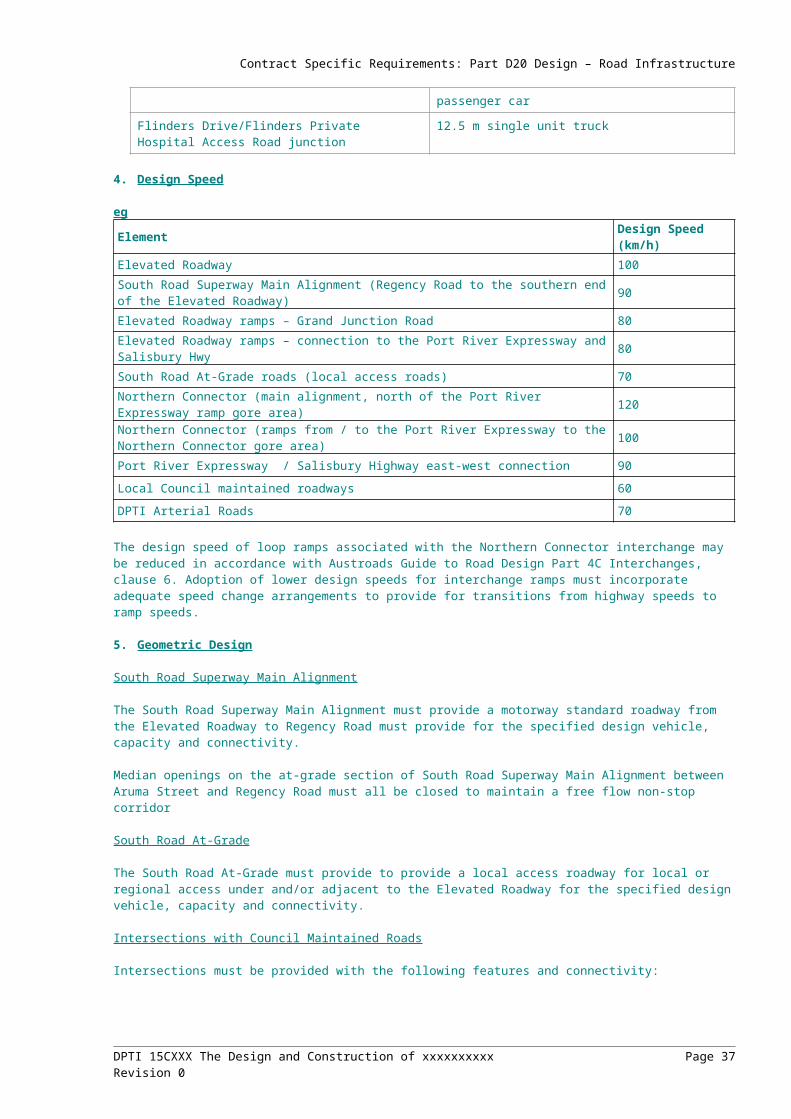
Contract Specific Requirements: Part D20 Design – Road Infrastructure
7.4. Fill Material Design Parameters
Design parameters for standard Type A and B fill materials (refer Part 210, Clause 15) are provided in the table below.
Material Design Parameter
Type A Fill E 70MPa
= 0.45
Type B Fill E 50MPa
= 0.45E = Vertical Resilient Modulus, = Poisson Ratio of all sub-layers
7.5. Design Subgrade Strength
The Principal has undertaken detailed pavement geotechnical investigations. The pavement Design CBR value(s) for the insitu subgrades must not be greater than the following:
(a) Ford Highway to Holden Road (not including intersection) CBR 2.5%
(b) Chrysler Road (including intersection) to Dodge Road CBR 4 %
7.6. Wearing Courses
The wearing course types are required as follows:
Location Asphalt Wearing Course
Main Carriageway Modified 40 mm SMA.
DPTI 15CXXX The Design and Construction of xxxxxxxxxx Page 37Revision 0

Contract Specific Requirements: Part D20 Design – Road Infrastructure
RampsModified 40 mm SMA, or Modified AC10 (heavy duty) at the approach to Regency Road intersection.
DPTI Arterial Roads Modified AC10 (medium or heavy duty)
Local Council roads AC10
Note:
(a) a sprayed seal is required below SMA wearing courses for waterproofing. A modified AC10 layer is required beneath the spray seal; and
(b) temporary wearing courses on asphalt bases which are trafficked between April & October are to be AC10.
An open graded asphalt wearing course may be considered as an alternative on the Main Carriageway upon demonstration of the proposed design with supporting evidence of the proposal to the satisfaction of the Principal. Acceptance of an open graded asphalt wearing course is solely at the discretion of the Principal.
7.7. Pavement Layer Thicknesses
Pavement layer thicknesses must comply with the DPTI Supplement to the Austroads Pavement Design Guide except for the following:
Pavement Layer Minimum Thickness (mm)
Asphalt on reinforced concrete superstructure 85mm; consisting of 40 mm SMA; spray seal; 35 mm AC10, spray seal (note: 5mm allowed for each spray seal)
4.3 Subsoil Drainage
Pavement subsoil drainage must be included within sections of cut.
Subsoil drainage must be connected to drainage pits within the drainage network at intervals of no more than 250m and must include flush out points with appropriate covers at intervals of no more than 100m.
4.4 Noise Assessment
The Principal’s noise assessment and resulting scope for noise mitigation for the project has been based on the use of Stone Mastic Asphalt (SMA) surfacing. If an alternative pavement option is proposed, the Contractor must:
(e) revise the noise assessment in line with DPTI's Road Traffic Noise Guidelines 2007;
(f) identify the noise mitigation requirements for the alternative pavement in accordance with DPTI's Road Traffic Noise Guidelines 2007 for comparison with the reference design pavement; and
(g) quantify the cost of the noise mitigation with the alternative pavement option for comparison with the reference design pavement.
Rehabilitation treatments of existing pavements are to be defined following completion of new pavement works and are not covered by this brief.
LIGHTING
Insert any specific lighting requirements here: eg underpass lighting, light monitoring and control system.
DPTI 15CXXX The Design and Construction of xxxxxxxxxx Page 38Revision 0

Contract Specific Requirements: Part D35 Design - Structural
PART D35 DESIGN - STRUCTURES
1. DESIGN REQUIREMENTS FOR BRIDGES
1.1. General
In addition to the requirements specified in Clause 4 of the DPTI Structural Design Standards, the structure design must comply with the requirements in this clause.
1.2. Fire Rating
The structure must be designed for a fire rating, in accordance with AS3600, of [Insert project specific, default 2hours].
1.3. Earthquake Design Provision
The bridge classification is Type II in accordance with 5100.2 and AS 1170.4,
1.4. Anti Graffiti Coating
Insert Details
1.5. Cathodic Protection
The bridge must incorporate provisions for the future installation of cathodic protection
1.6. Substructures
Pile caps must be designed so the top of the pile cap is below ground level or the underside out of sight at low water level.
1.7. Aesthetic Requirements
The aesthetics of structures must be in accordance with the requirements included in Part D037 Design – Landscape and Urban Design.
1.8. Requirements for Future Expansion of the Works
Insert details for any future widening etc.
Example wording for extension of reinforced soil structure:
The design of the reinforced Soil Structure must allow for both initial and future configurations. The walls may be extended in height (ie. wingwalls extended to form widened bridge abutments along future road duplications) at the following locations:[Insert locations here]
At these locations, the soil reinforcement and facing panels constructed under this Contract must be designed to support the extended wall and any additional surcharge without modification (except for removal of non-standard capping panels). For walls that are to be extended laterally, the extension must be able to be constructed without disturbing reinforcing straps that are to remain in place and without compromising the integrity of the temporarily excavated reinforced earth block due to scour or soil instability.
2. INTERPRETATION OF THE BRIDGE DESIGN STANDARD
The design must be undertaken using the clarifications and interpretations of AS 5100 Bridge Design contained within this Clause.
AS 5100 must be read to incorporate the corrections listed in Appendix 1: “AS 5100 – Corrections”. The Design Report must include details of any additional interpretations or clarifications proposed.
DPTI 15CXXX The Design and Construction of xxxxxxxxxx Page 39Revision 0
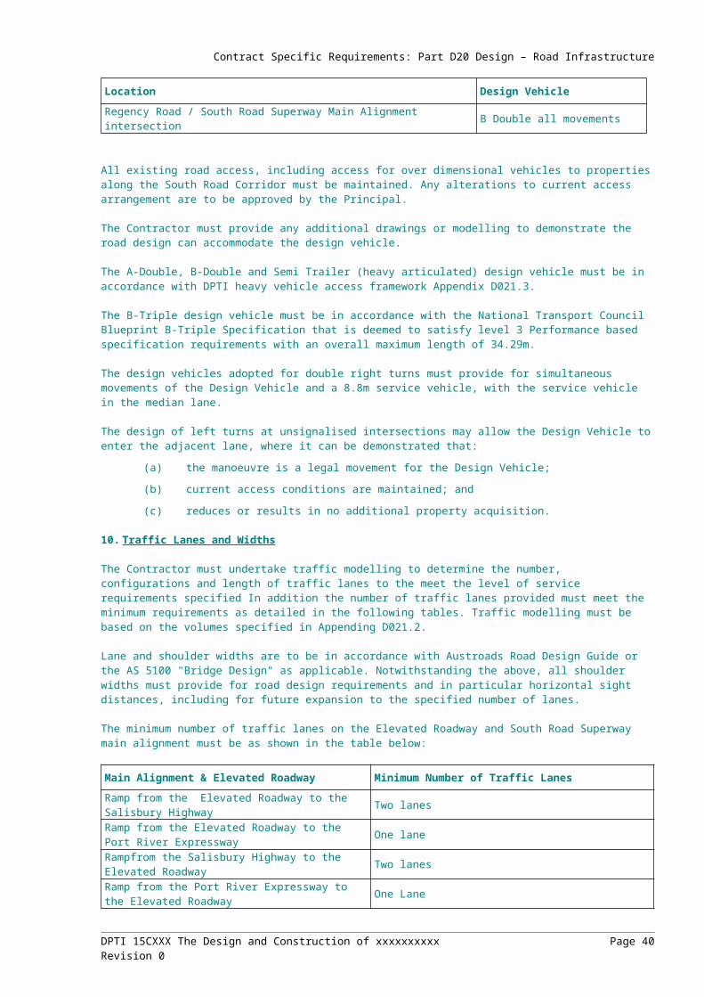
Contract Specific Requirements: Part D35 Design - Structural
Clause Requirement
AS 5100.1 – 6.2 "Design Life"
ELEMENT DESIGN LIFE (Years)
Other urban design elements 50 Insert any other requirements here
AS 5100.1 – 9.2"Railway Bridges"
Insert details if relevant
AS 5100.1 – 9.4 "Road Bridge Carriageway Widths"
Insert Details if relevant
AS 5100.1 – 9.7“Vertical Clearance over Roadways"
Insert details if relevant
AS 5100.1 – 9.11 "Pedestrian Bridges"
Insert details if relevant
AS 5100.1 – 10 "Road Traffic Barriers"
Insert details if relevant
AS 5100.2 – 6.3 "Heavy Load Platform"
Insert details if relevant
AS 5100.2 – 8"Railway Traffic"
Insert details if relevant
AS 5100.2 – 11.2.2"Traffic Barrier Design Loads"
Insert details if relevant
AS 5100.1 – 12.3 “Protection screens for objects falling or being thrown from bridges.”
Specify if protection screens are required – otherwise the defaults in Clause 9 of the Design Standard will apply.
3. MATERIALS AND DURABILITY
4.1 Steelwork
Selection of the system must be based on table 6.3 of AS 2312 for the appropriate corrosivity category ……Insert coating system details here eg:
The coating system used must be selected from the following system designations, as detailed in Table 6.3 of the 2004 amendment to AS/NZS 2312:
(a) EHB6 (Primer must be PRN C01a, C01b or C01c).
(b) PSL1 (System must include an additional intermediate coat of PRN C13 epoxy MIO to 125µm).
(c) PUR5 (Primer must be PRN C01a, C01b or C01c).
(d) Where a decorative or aesthetic finish is desired, only systems PSL1 and PUR5 may be used.
4.2 Durability Plan
A Durability Plan is/ is not required
Submission of the Durability Plan shall constitute a HOLD POINT.
4. DESIGN REQUIREMENTS FOR NOISE BARRIERS
Insert any specific requirements for noise barriers here.
DPTI 15CXXX The Design and Construction of xxxxxxxxxx Page 40Revision 0

Contract Specific Requirements: Part D37 Landscape and Urban Design
PART D37 DESIGN - LANDSCAPE AND URBAN DESIGN
4. DESIGN REQUIREMENTS
Example wording below:
4.1 General
The Contractor must provide integrated landscape and urban design solutions for all components of the project works, including the integration of:
(a) landscaping and revegetation;
(b) structures, including urban design finishes and treatments;
(c) lighting, including feature lighting;
(d) signage, including support structures;
(e) acoustic control and road furniture, including noise and safety barriers;
(f) public art; and
(g) landscape maintenance access devices.
The Landscape Architect(s)/Urban Designer(s) must work collaboratively as part of a multidisciplinary team. In developing the landscape and urban design, the Contractor must:
(a) ensure compliance with all safety requirements;
(b) ensure the landscape design incorporates offsets for impacted native, amenity, regulated and significant vegetation in accordance with the DPTI Vegetation Removal Policy, Native Vegetation Act 1991 and Development Act 1993, where relevant;
(c) ensure the interrelationship of individual design elements and consider their relationship to the whole;
(d) ensure that the development of the design is such that appropriate landscape and urban design solutions are developed for all visible areas of the project;
(e) ensure the landscape and urban design is fully coordinated and integrated with road infrastructure and utility services so as to compliment without compromising structural integrity, functionality or access;
(f) ensure the infrastructure strengthens the local character of the area by responding to the social, cultural and environmental characteristics;
(g) ensure the design is capable of evolving with operational requirements and changing community attitudes;
(h) ensure safe, efficient and legible circulation routes for pedestrians, cyclists and people with disabilities;
(i) ensure a high standard of design to achieve quality infrastructure that is visually attractive and interesting, sophisticated and contemporary; and
(j) incorporate sustainable design principles such as water management, energy efficiency and biodiversity.
4.2 Access and Movement
The project should enhance and improve the connectivity and safety of vehicle, pedestrian and cyclist routes within and adjacent to the corridor.
The zone directly beneath the structure should be considered as ‘positive’ space that maximises east-west cross movement for vehicles, cycles and pedestrians. Opportunities to activate this space through the inclusion of pedestrian and cycle paths, water sensitive urban design and ‘green’ space should be explored. This space may also be appropriate for public art.
The Design Criteria include:
(a) Achieve ‘positive’ space beneath the structure that has active uses and is attractive in appearance.
DPTI 15CXXX The Design and Construction of xxxxxxxxxx Page 41Revision 0

Contract Specific Requirements: Part D37 Landscape and Urban Design
(b) Achieve movement corridors beneath and/or adjacent to the structure by providing appropriate connections to adjacent properties and local/arterial roads.
(c) Minimise ‘left-over’, ‘negative’ or purely visual spaces beneath the structure that lack positive surveillance and activation.
The Technical Requirements include:
(a) Wherever possible, improve pedestrian and cycle movement lines across the local access roadway to maintain and enhance connections between adjacent land uses and zones.
(b) Select materials, proportion spaces and plan uses to support the variety of spaces within the road corridor and position these in relation to each other for compatibility of uses and continuity of access and movement.
(c) Create opportunities for adjacent existing uses to engage with new uses beneath and beside the structure, enhancing, where possible, their amenity and function.
(d) Ensure the project does not restrict or prevent access to adjacent uses; if necessary, provide for new entries and connections to cycle and pedestrian networks.
4.3 View Corridors
Provision of view corridors will create amenity within the project corridor, taking advantage of the structure and generally flat topography along the project route. Controlling and directing views should contribute towards way-finding and orientation, and should help to reinforce a pleasurable and memorable journey.
(a) Enhance amenity and legibility from the structure by recognising and reinforcing view corridors through to Port Adelaide and the Adelaide Hills escarpment.
(b) Ensure the structure does not obscure important view corridors.
(c) Ensure the landscape and urban design treatments enhance the view corridors along approach roads to the structure.
The Technical Requirements include:
(a) Enhance way-finding and place-making by providing points of recognition along the route.
(b) Allow views from the structure into the adjacent suburbs recognising particular landmarks and points of interest, both built and natural.
(c) Allow long distance views from the structure to the large-scale infrastructure landmarks visible at Port Adelaide and east to the Adelaide Hills escarpment.
4.4 Safety
4.4.1 Sight Visibility
The Design Criteria include:
(a) Ensure driver sight distance and visibility are not compromised by landscape and urban design elements and treatments.
The Technical Requirements include:
(a) Vegetation must not exceed a maximum height of 500mm above the finished road surface in areas where sight distance requirements must be achieved.
(b) Urban design treatments must comply with sight distance requirements.
4.4.2 Clear Zones
The Design Criteria include:
(a) Clear zones must not be compromised by landscape and urban design treatments and elements.
The Technical Requirements include:
(a) Careful consideration must be given to the placement and urban design integration of any safety barriers to protect traffic from piers within clear zones.
4.4.3 Road Safety
The Design Criteria include:
DPTI 15CXXX The Design and Construction of xxxxxxxxxx Page 42Revision 0

Contract Specific Requirements: Part D37 Landscape and Urban Design
(a) Landscape and urban design treatments must be designed to prevent debris and obstacles entering roadways and must assist in reducing driver distraction.
(b) Provide a level of visual variety and interest that promotes driver alertness and awareness of the road corridor environment.
The Technical Requirements include:
(a) Low sheen, non-reflective urban design finishes should be used to minimise headlight and sun glare.
(b) Avoid the use of loose stone/gravel mulch in roadway areas where errant vehicles could throw mulch onto the roadway or where it could spill on to pedestrian/cyclist pathways or be thrown/dropped on to roadways.
(c) Transparent materials must be shatterproof.
(d) Urban design treatments must be simple, clutter-free and easily interpreted without causing driver distraction.
4.4.4 Pedestrian and Cyclist Safety
The Design Criteria include:
(a) Pedestrian and bicycle facilities must be safe, user friendly and integrated with the road design.
The Technical Requirements include:
(a) Consider CPTED principles in the design of pedestrian and bicycle facilities.
(b) Where appropriate, provide signalised crossings for pedestrians and cyclists.
(c) Landscape and urban design treatments must comply with sight distance and clearance requirements.
(d) A high level of shade should be provided to pedestrian and bicycle facilities.
(e) Landscape and urban design treatments should be designed to increase driver awareness of pedestrian and bicycle facilities.
(f) Provide clear and legible entries and exits to adjacent properties.
4.4.5 Adjacent land use
The Design Criteria include:
(a) Provide landscape and urban design treatments that satisfy the safety requirements of adjacent land use bordering the corridor.
The Technical Requirements include:
(a) Ensure landscape treatments are designed and installed in accordance with the requirements of service authorities.
(b) Ensure the needs and expectations of adjacent property owners and tenants are considered in the landscape and urban design.
4.5 Architectural Character
The architectural character of the project should be fresh and contemporary, reinforcing an integrated view to urban infrastructure provision that sees building communities as an important part of project provision.
Under-pinning the project is a commitment to environmentally sustainable design and an aesthetic that respects the existing urban context, street and built form morphology, and land uses through which the project passes.
Composition, detailing and material selection of architectural elements should be carefully considered, with an emphasis on creatively resolving architectural forms and finishes.
The Design Criteria include:
(a) Attain a high standard of architectural built form and detail.
(b) Reinforce a contemporary character to the project and associated public realm development.
(c) Apply Best Practice building design, detailing and servicing strategies to minimise environmental impact in construction and operation
DPTI 15CXXX The Design and Construction of xxxxxxxxxx Page 43Revision 0

Contract Specific Requirements: Part D37 Landscape and Urban Design
The Technical Requirements include:
(a) Respond to the immediate site context, and the character of adjoining streets and open spaces.
(b) Acknowledge and respond to the cultural context, grounded in the immediate locale but also extending beyond the corridor.
(c) Develop fresh, contemporary architectural outcomes in built form and detail.
(d) Consider passive climate design strategies to ameliorate the effects of the structure.
(e) Explore opportunities presented by contemporary structural, material and environmentally innovations and technologies.
(f) Consider spatial sequences that support, at ground level, a rich driver, pedestrian and cyclist experience, taking into account the linearity of the structure undercroft and perpendicular connecting streets and open spaces.
(g) Select materials, proportion spaces and plan uses to give a variety of visual, audible and tactile spatial experiences in the undercroft spaces.
(h) Modulate the scale of the architectural elements to allow for both compositional clarity at a distance and a richly detailed, fine grained pedestrian experience up close.
(i) Orient and manipulate screens and noise barriers in response to differing view opportunities on the structure and at ground level.
(j) Mitigate unfavourable impacts from the structure, such as overshadowing and wind acceleration and turbulence on adjacent public open space and private land.
(k) Adopt materials, colours and textures from a prescribed palette, applied creatively to reinforce definition of spaces, built form elements and uses.
(l) Integrate utilities and services within the structural profile to eliminate visible clutter.
4.6 Bridge Form and Detailing
4.6.1 General
(a) The bridge must present smooth, clean lines and must have a minimal structural depth consistent with its spans and construction method.
(b) Provide a neat, clean and integrated transition/interface between all structural elements.
(c) Concrete must be finished smoothly with no bubbles, chips or staining.
(d) Provide free-draining finishes and joint detailing which minimises water retention, litter traps and potential chemical, mould and dirt staining.
(e) Provide neat, clean finishes to all outer exposed edges.
(f) Provide chamfered surface finishes to all exposed edges.
(g) Provide detailing that minimises potential creation of roosting sites for birds and bats.
(h) Provide design integration to ensure that utility services are concealed from view.
4.6.2 Piers and Pile Caps
The supporting piers will be a visually dominant element in the urban landscape. Their detailed design is an important part of the visible face of the architecture of the project, establishing the quality of composition, proportion, detailing and materials selection.
The Design Criteria include:
(a) Pier composition, proportion, detailing and materials selection should provide a light, elegant and contemporary character for the project.
The Technical Requirements include:
(a) Ensure that piers and headstock are visually integrated.
(b) Ensure an integrated suite of pier shapes.
(c) Ensure piers are slender and elegant in proportion and appearance.
(d) Align piers to minimise visual clutter at ground level.
DPTI 15CXXX The Design and Construction of xxxxxxxxxx Page 44Revision 0

Contract Specific Requirements: Part D37 Landscape and Urban Design
(e) Consider the architectural design of the piers and box truss as one, integrating proportions, detailing and materials.
(f) Avoid visible pile caps at the base of piers; rather take the piers directly into the ground hiding the base and footings.
(g) Consider the appearance and proportions of the piers in profile from all directions – when viewed along the line of the local access roadway, from perpendicular cross streets and from adjacent properties.
(h) Consider the visual effect of void spaces created by piers when viewed at ground level.
4.6.3 Façades, Parapets and Barriers
Along with the supporting piers, the side elevation of the structure will be a dominant visual element of the superstructure. Its visual prominence will be increased by the height of the carriageway above the adjacent areas and its continuous, horizontal nature.
The Design Criteria include:
(a) Provide an articulated design outcome that is visually ‘light’ within the urban landscape.
The Technical Requirements include:
(a) Angle the top of structure parapets/barriers towards the roadside to direct rainwater onto the bridge, avoiding staining on the outside face.
(b) Parapet soffit must extend below the bridge deck soffit to hide any complex details.
(c) Provide a neat and integrated connection between the parapet (including ends) and the bridge structure.
(d) Provide a neat and integrated connection between the safety barrier system and the parapet.
(e) Articulate the lines and flat planes of the façades (for example, joints between panels) with other sub- and super-structure elements, including columns, embankment walls and minor elements such as barriers, noise walls and light poles.
(f) Select natural materials not requiring external finishes so they do not require recoating or on-going refinishing.
(g) Consider the use of neutral background colours with more colour-rich lines and flat planes used as accents. Give preference to the ‘earthy’ natural colours of the landscape rather than bolder primary colours that may fade or date. Use primary colours only for accent or to express particular architectural elements, lines or planes.
(h) Only include artwork where it is an integral part of the overall composition.
(i) Put equal design effort into the quality of fittings, joins and minor elements, so that they compliment the architectural design of project.
(j) Consider the proportions and scale of flat panels comprising walls, abutments and fascias. Articulate the panels by join lines or other means to achieve architecturally satisfying proportions.
(k) Consider the length of the structure as one composition that may be broken up into differing parts but which share common proportions, articulation, lines, forms and scale.
(l) Include planting as an integral component of the overall composition, including the inclusion of architectural plantings where these contribute positively to the overall visual effect and amenity.
4.6.4 Box Truss
The underside of the structure is an important visual plane that will be visible from adjacent areas. The shape and finish of the box truss must be carefully designed and detailed to compliment the shape of other super-structure elements.
The Design Criteria include:
(a) Design of the box truss must contribute towards the overall architectural design outcome.
The Technical Requirements include:
(a) Articulate the lines and flat planes of the underside with other and super-structure elements, including barriers, piers, embankment walls and minor elements.
DPTI 15CXXX The Design and Construction of xxxxxxxxxx Page 45Revision 0

Contract Specific Requirements: Part D37 Landscape and Urban Design
(b) Conceal all service conduits, including electrical, water supply and stormwater. No conduits or pipes should be visible unless these are visually integrated into the overall architectural expression and aesthetics.
(c) In determining the surface colour of the underside, consider the overall colour scheme for the architectural elements of the project and provide complimentary colours and finishes to the underside.
(d) Ensure a clean, uncluttered appearance to the underside by articulating and proportioning structural and cladding elements.
(e) Consider the length of the structure as one composition that may be broken up into differing parts, but which shows common proportions, articulation, lines, forms and scale.
(f) Consider the use of long, smoothly tapered haunches that provide a continuously diminishing width rather than short, abrupt haunches.
4.6.5 Minor Infrastructure Elements
The Design Criteria include:
(a) Provide an integrated architectural design for all minor road infrastructure elements.
(b) Use materials and techniques that require low maintenance and are robust and durable.
(c) Achieve an aesthetically pleasing design outcome that favours ‘simple’ clean lines and utilises attractive and contemporary materials.
The Technical Requirements include:
(a) Consider the view of the minor elements from adjacent areas as well as the view of these elements from vehicles travelling along the structure.
(b) Consider the relationship of minor elements to the road super-structure as well as to each other. Achieve a consistent, integrated and visually cohesive design outcome.
(c) Consider visually solid, transparent and translucent elements as a means of enclosing, blocking or opening views from the structure.
(d) Achieve consistency of materials, finishes and colours supporting the overall architectural design objectives. This does not necessarily mean a sameness in the design of these elements, but rather a consistency with an overall design approach that supports the architectural design objectives.
(e) Ensure the junction between elements achieves an integrated design outcome – for example, design noise barriers to visually integrate with the overall composition of the structure.
(f) Utilise only low maintenance materials. Avoid external finishes that require on-going maintenance.
(g) Give preference to elements designed for this particular application, rather than universal design solutions (for example, avoid the use of standard pool fencing).
4.6.6 Noise Barriers
The Design Criteria include:
(a) Provide noise barriers to achieve the required noise criteria at sensitive receivers.
(b) Integrate noise barriers with other barriers to provide consistent heights and proportions.
The Technical Requirements include:
(a) Meet all requirements for noise mitigation.
4.6.7 Reinforced Earth Walls and Retaining Walls
The Design Criteria include:
(a) Design of reinforced earth walls must be integrated with urban design outcomes.
The Technical Requirements include:
(a) Provide standardised formwork that can be replicated in the future.
(b) Consider the visibility and exposure of vertical faces to users and the opportunity for public art in place making
(c) Provide wall surfaces and detailing that are consistent with the design intent and detailing of other architectural elements.
DPTI 15CXXX The Design and Construction of xxxxxxxxxx Page 46Revision 0
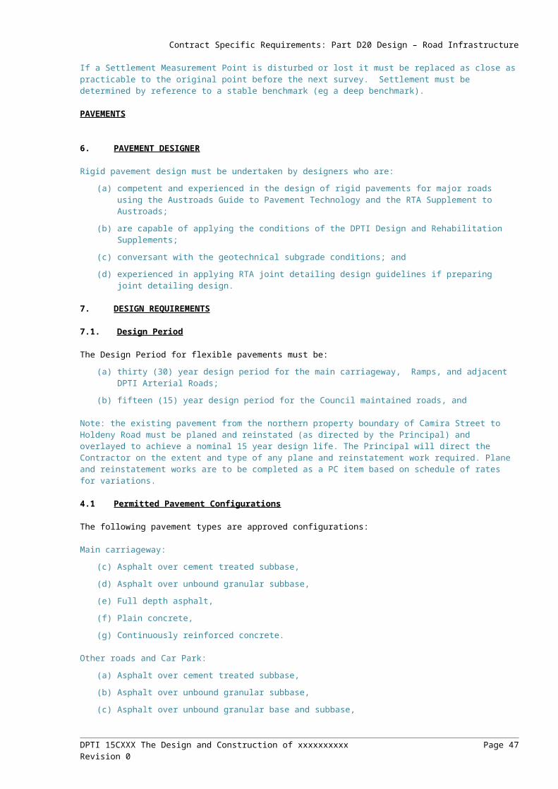
Contract Specific Requirements: Part D37 Landscape and Urban Design
(d) Ensure surfaces do not provide hand or foot holds or roosting opportunities
4.6.8 Fencing
The Design Criteria include:
(a) Design of fencing must be integrated with urban design outcomes.
The Technical Requirements include:
(a) Provide consistent fencing types within the road reserve.
(b) Maximise consistency of fencing for properties adjoining the road reserve.
(c) Use of standard pool fencing should be avoided.
4.6.9 Gantries and Major Sign Structures
The Design Criteria include:
(a) Design of gantries must be integrated with urban design outcomes.
The Technical Requirements include:
(a) Provide high quality urban design detailing to permanent gantries for signage/ITS.
4.6.10 Lighting
The Design Criteria include:
(a) Provide a feature lighting design that enhances the appearance of the structure at night.
(b) Use lighting to provide safety and security for pedestrians and cyclists.
(c) Provide feature lighting to reinforce entry points and key features along the route for motorists.
(d) Design of light poles must be integrated with urban design outcomes.
The Technical Requirements include:
(a) Select feature lighting that is energy efficient, utilising LED fittings where possible.
(b) Carefully locate lighting to prevent ‘cluttering’ of the public realm and, where appropriate, integrate with other elements such as barriers and piers.
(c) Ensure light pole and luminaire proportions fit into the streetscape with minimal visual impact on the streetscape character.
(d) Provide direct light where required without ‘washing out’ or over-illuminating adjacent areas.
(e) Locate light fittings in an integrated way with other architectural elements, providing regular spacing and articulation.
(f) Use robust, vandal resistance and low maintenance fittings.
(g) Ensure consistency in architectural expression by consideration of form, materials and colours of light poles and fittings.
(h) Light poles must be designed for ease of luminaire replacement.
(i) Light poles must be designed for ease of replacement in the event of irreparable damage.
4.6.11 Field Cabinets
The Design Criteria include:
(a) Design, colour, form and placement of field cabinets must be considered with respect to desired urban design outcomes.
The Technical Requirements include:
(a) Integrate cabinetry with street furniture and provide consistent materials, colours and finishes.
(b) Integrate locations and footings with planting and other softscape surfaces.
4.6.12 Street Furniture
The Design Criteria include:
DPTI 15CXXX The Design and Construction of xxxxxxxxxx Page 47Revision 0
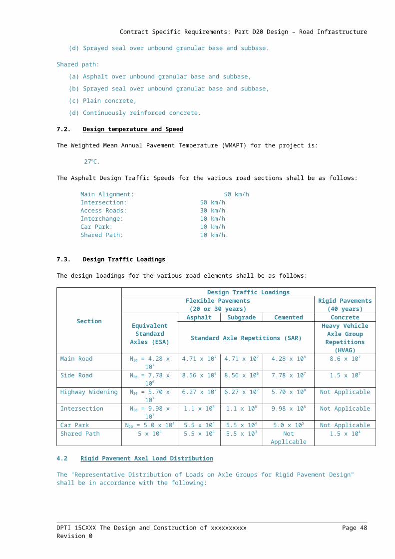
Contract Specific Requirements: Part D37 Landscape and Urban Design
(a) Provide street furniture that contributes towards the successful functioning of the South Road precinct at pedestrian scale, increasing amenity and supporting active use at street level.
(b) Provide new street furniture including (but not limited to) seating, bins and bike racks.
The Technical Requirements include:
(a) Carefully place street furniture to prevent ‘cluttering’ of the public realm.
(b) Street furniture must fit into the streetscape with minimum visual impact on the streetscape character.
(c) Ensure robust construction and inclusion of skateboard deterrent features where appropriate to reduce unnecessary maintenance costs.
(d) Provide consistent architectural expression through consistency in form and materials.
(e) Street furniture must be constructed of materials that are complimentary to the project architecture.
(f) Street furniture must be BCA and DDA approved.
(g) Street furniture must be located within areas of high intensity public and recreational use e.g. bench seats should be located at street level along the footpath/shared path to provide rest points and viewpoints.
(h) Street furniture must be positioned to reflect the recreational and community uses of the specific site.
4.7 Materials, Colours and Finishes
The materials, colours and finishes selected for all infrastructure elements should enhance their character and personality, and in doing so, improve the journey experience and the way the project integrates into the surrounding area. Choice of materials should reflect and reinforce a local sense of place, a contemporary appearance and preference for sustainable products.
The Design Criteria include:
(a) Attain a high standard of architectural built form and detail.
(b) Provide a high level of amenity for pedestrian environments.
(c) Reinforce a contemporary character to the overall project that reflects a concern for good design.
(d) Achieve robust, low maintenance finishes.
The Technical Requirements include:
(a) Select materials that together constitute a consistent palette that reinforce a local identity for the project and express a contemporary architectural character.
(b) Select materials for permanence and durability.
(c) Select materials with an understanding of the effects of weathering over a period of time to ensure an enduring high quality finish.
(d) Use materials that weather in a manner that enhances the material and allows ongoing change without reduction in the inherent qualities of the materials.
(e) Select materials for low on-going maintenance. Utilise materials that do not require on-going recoating or refinishing.
(f) Select materials to provide a variety of visual, audible and tactile spatial experiences, particularly when viewed at ground level.
(g) Select materials for their low embodied energy and potential for future reuse or recycling.
(h) Where materials are experienced close at hand, utilise materials such as timber to bring warmth and a human tactile quality to key architectural elements.
(i) Utilise materials that are not highly reflective to avoid glare or focused transfer of heat.
4.8 Public Art
Public art is considered an integral part of the road infrastructure, providing points of reference and interpretation along the route. Public art contributes towards an enjoyable and memorable journey.
The Design Criteria include:
DPTI 15CXXX The Design and Construction of xxxxxxxxxx Page 48Revision 0
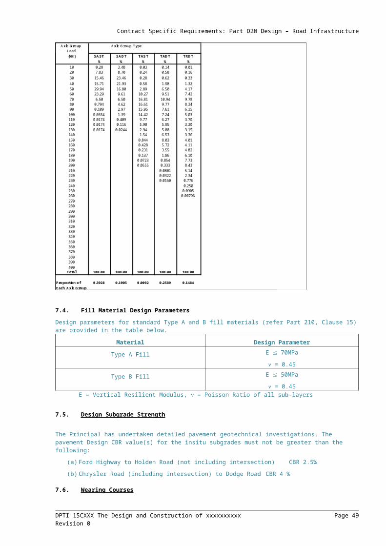
Contract Specific Requirements: Part D37 Landscape and Urban Design
(a) Integrate public art with the architectural design of the project.
(b) Provide meaningful landmarks and reference points along the route.
The Technical Requirements include:
(a) Consider public art as a means of contributing towards the overall experience of travel, integrating art, where possible, within items of road infrastructure (e.g. noise barriers, RE walls) and as stand-alone commissioned pieces.
(b) Design and select public art for its compatibility for purpose integrating with, and complimenting, other urban design and architectural elements.
(c) Design and select public art for its appropriateness to the urban context of the project - consider, above all, sense of identity and ‘place’.
(d) Ensure only robust and durable materials and finishes are used and that, overall, the public art has no or low maintenance requirements.
(e) Favour public art expressed elegantly and boldly, avoiding intricate or fussy designs.
(f) Favour public art that is both contemporary and timeless.
5. LANDSCAPING
5.1 General
Planting of the ground plane beneath and adjacent to the project will contribute towards the overall architectural composition and assist in the visual integration of the project into its surroundings. Planting will contribute towards character and sense of place, provide visual amenity and improve biodiversity.
The Design Criteria include:
(a) Compliment the physical structure of the structure and assist in its visual integration with the adjacent urban area.
(b) Provide amenity and usable open space in areas beneath and adjacent to the structure.
The Technical Requirements include:
(a) Utilise low maintenance techniques such as mulch and automatic drip irrigation. Select plant species that have low irrigation requirements and do not require ongoing fertilising and pruning.
(b) Only use species suited to the local soils and microclimates.
(c) Give preference to the use of local native plants and species that are available from local growers.
(d) Utilise techniques that eliminate weed infestation including soil preparation and mulching.
(e) Avoid over fussy or visually complex designs.
(f) Favour controlled use of colour and foliage textures.
(g) Consider seasonal differences and variety.
(h) Include plants with distinctive form, foliage and colour where this contributes towards points of identity and recognition, and an overall sense of place.
(i) Consider ecological sustainability, biodiversity and habitat creation.
(j) Minimise irrigation requirements through species selection, conditioning of site soils and the use of mulches.
(k) Select species for their ultimate height and growth habits. Only use species that will not become ‘woody’ over time and generally do not require pruning.
(l) Do not select species that are vulnerable to being damaged from foot traffic in public areas.
(m) Consider CPTED principles in the selection and location of plants.
5.2 Road Corridor Vegetation
The Design Criteria include:
(a) Provide an attractive, well-vegetated road reserve with landscape plantings appropriate for the function, safety requirements and visual significance of the road corridor.
DPTI 15CXXX The Design and Construction of xxxxxxxxxx Page 49Revision 0
Contract Specific Requirements: Part D37 Landscape and Urban Design
(b) Landscape and urban design treatments must contribute to the rehabilitation and enhancement of the existing environment and serve as a catalyst for the general improvement of areas adjacent to the road corridor
The Technical Requirements include:
(a) Landscape treatments must cover all off-road areas within the extent of site.
(b) Consideration should be given to extending landscape treatments into the arterial and/or local road network, if they will enhance the environmental outcomes or visual amenity of the project.
(c) Maximise the use of low maintenance treatments and minimise the use of high maintenance treatments.
(d) Apply the aesthetic use of plant material to enhance precincts, gateways and views without compromising safety, function or practicability of maintenance.
(e) Provide for successional replacement and replenishment of landscape treatments (to account for natural plant failure) as landscaped areas develop.
(f) Landscape works must be maintained throughout the maintenance phase so that they satisfy the required performance benchmarks at handover.
5.3 Swales, Detention Basins and Wetlands
The Design Criteria include:
(a) Provide Water Sensitive Urban Design solutions to filter and improve water quality and make efficient use of natural rainfall for plant irrigation.
(b) Provide dense macrophyte plantings to swales, detention basins and wetlands.
(c) Plantings must be specified and installed in a manner that will assist in stabilising soil, provide habitat and capture contaminants.
(d) Provide low maintenance treatments that consider weed, siltation, spill and trash management, and provide maintenance access.
(e) Provide control and holding zones to minimise the impact of chemical spills or harmful liquids entering the water system.
(f) Consider the movement of birds and animals from adjacent areas to water corridors.
The Technical Requirements include:
(a) Drainage devices must be integrated into the landscape.
(b) Vegetation densities and placement must not compromise drainage requirements.
(c) Drainage design must provide berms and benches of sufficient area at depths that will allow for the establishment of macrophytes.
(d) Consider use of natural and rock surfacing to direct water flows and slow water velocity.
(e) Integrate pits and junctions with planting at appropriate heights and densities to maintain flow.
(f) Direct water to planting areas for natural filtration.
5.4 Batters
The Design Criteria include:
(a) Design of batters must be integrated with landscape and urban design outcomes
The Technical Requirements include:
(a) Fill embankment batter gradients must not exceed 1:2 where dependent on vegetation for surface stabilisation.
(b) Smooth tapered transitions must be provided between earthworks (including cuttings and embankments) and existing landform.
(c) Hinge points at top and bottom of cuttings and embankments must be rounded off.
(d) Install appropriate erosion control devices and landscape treatments to maintain slope mass and surface stability.
(e) Provide necessary soil stability and amelioration treatments required for successful establishment of vegetation.
DPTI 15CXXX The Design and Construction of xxxxxxxxxx Page 50Revision 0
Contract Specific Requirements: Part D37 Landscape and Urban Design
5.5 Medians and Splitter Islands
The Design Criteria include:
(a) Integrate all ground surface treatments, clearly defining trafficable and non-trafficable areas and those accessible by pedestrians and cyclists.
The Technical Requirements include:
(a) Provide hard surfaces on medians and splitter islands less than 2.0 m wide.
(b) Provide trafficable materials that will withstand maintenance and emergency vehicles.
(c) Consider opportunities for Water Sensitive Urban Design, particularly the collection of stormwater run-off into swales and bio-remediation pits.
(d) Where ‘soft’ surfaces are used, provide edges to contain the material.
(e) Provide ‘hard’ surfaces for pedestrian and cycle paths, or where surface stormwater flows are likely to cause erosion.
5.6 Rehabilitate Disturbed Areas
The Design Criteria include:
(a) Stabilise, restore and enhance disturbed areas as early as possible throughout the construction period.
The Technical Requirements include:
(a) Use only native species and prioritise the use of local species.
(b) Use species that will establish readily in disturbed areas and will tolerate the new site conditions (e.g. increased shade from structure and decreased rainfall beneath).
(c) Minimise the transfer and introduction of undesirable plant species during earthworks and rehabilitation activities.
(d) Disturbed and/or newly created riparian zones (including wetlands and drains) must be returned to conditions suitable for recolonisation of riparian species, including recontouring of bank profiles to create necessary habitat conditions relative to water levels.
5.7 Mitigate Negative Sensory Impacts
The Design Criteria include:
(a) Mitigate potential negative visual and noise impacts on the locality and/or the project works.
(b) Minimise incompatibilities of treatments between the road corridor and adjoining land uses.
The Technical Requirements include:
(a) Mitigate visual impacts into and out of the road corridor with landscape treatments such as screening/buffer plantings and mounding, and urban design features such as fences or noise barriers.
(b) Consult adjoining property owners to integrate landscape and urban design treatments with existing and proposed developments.
5.8 Mitigate Environmental Impacts
The Design Criteria include:
(a) Provide landscape and urban design treatments that mitigate environmental impacts on the locality.
The Technical Requirements include:
(a) Maintain or improve water quality by designing landscape treatments that treat storm water before discharge into the Barker Inlet Wetlands.
(b) Wetland plantings in drainage and sediment control devices must provide habitat and assist in meeting water quality requirements.
(c) Minimise habitat pollution (from materials such as oil, fuel, cement, bitumen, solvent and cleaning agent contaminants, pesticides, fertilisers and road runoff) through the provision of temporary/permanent detention basins and vegetation buffers.
DPTI 15CXXX The Design and Construction of xxxxxxxxxx Page 51Revision 0
Contract Specific Requirements: Part D37 Landscape and Urban Design
5.9 Community Considerations
The Design Criteria include:
(a) Provide landscape and urban design treatments that address the commercial/industrial and community interests of the region.
(b) Minimise adverse effects on the local character, lifestyles, economies and property values.
(c) Select and use landscape and urban design treatments that will not become dated over time.
The Technical Requirements include:
(a) Provide vegetation screens and buffers at interfaces with sensitive land uses.
(b) Implement ‘classic’ design treatments that provide a level of enduring community appeal and status over time.
(c) Provide opportunities for stakeholder/community participation in the development of landscape and urban design themes and treatments.
(d) Ensure landscape and urban design treatments involving public art are well coordinated to avoid inconsistency of themes/messages and coordinate details including colours, textures and finishes.
5.10 Maintenance
The Design Criteria include:
(a) Provide landscape treatments that will become self-sustaining over time and are cost effective with regard to ongoing maintenance.
(b) Provide urban design treatments that are durable and require minimal maintenance and refurbishment over time.
(c) Provide for easy replacement of urban design components in the event of non-recoverable damage – consider this at the design stage.
(d) Provide landscape and urban design treatments that incorporate Prudent Industry Practice for Anti-graffiti.
The Technical Requirements include:
(a) Urban design materials and components must be weatherproof and UV resistant with a minimum 20-year design life.
(b) Metal structural components, fixings, fasteners etc. must use corrosion resistant materials, manufacturing processes and/or finishes.
(c) Paint finishes must have a minimum 10-year design life.
(d) If colour is required, use painted colour treatment for concrete structures, rather than integrated colour additives, whilst maintaining urban design intent.
(e) All urban design treatments and construction materials must be robustly designed to deter and minimise the effects of vandalism. The design must provide surface finishes and treatments (e.g. paint, anti-graffiti coatings) that can be easily and efficiently maintained whilst still maintaining the urban design intent.
(f) Provide free-draining finishes and detailing that minimises water ponding sites that create potential for chemical, mould and dirt staining.
(g) Materials and finishes must be resistant to dust adherence.
(h) Materials and finishes must be resistant to cleaning fluids and procedures.
(i) The design, materials and finish of urban design treatments must provide accessibility and ease of mechanical cleaning procedures.
(j) Urban design detailing must minimise potential for creating litter traps.
(k) Metal security grilles/cages must be provided to protect all lighting that has the potential to be vandalised.
(l) Provide concrete or gravel mowing strips where grass areas abut landscape planting areas.
(m) Minimise grass areas that require slashing/mowing.
DPTI 15CXXX The Design and Construction of xxxxxxxxxx Page 52Revision 0

Contract Specific Requirements: Part D37 Landscape and Urban Design
(n) Where grassing is provided, ensure the area is not steeper than 1:3 and select low growing/creeping grass species.
(o) Avoid narrow strips of vegetation in and around guard rail, noses of medians and splitter islands and fencing alignments. Median and splitter island areas narrower than 2m should be treated as hardstand (paving, concrete, asphalt or crushed rock).
5.11 Maintenance Access Requirements
The Design Criteria include:
(a) Provide off-road access for maintenance activities where space permits.
(b) Project works must be designed to permit maintenance activities to be carried out without endangering maintenance crews and road users with minimal disruption to traffic flows.
The Technical Requirements include:
(a) Provide permanent off-road maintenance areas/tracks for critical areas requiring ongoing maintenance including landscaping, drains, sedimentation ponds, structures and services.
DPTI 15CXXX The Design and Construction of xxxxxxxxxx Page 53Revision 0
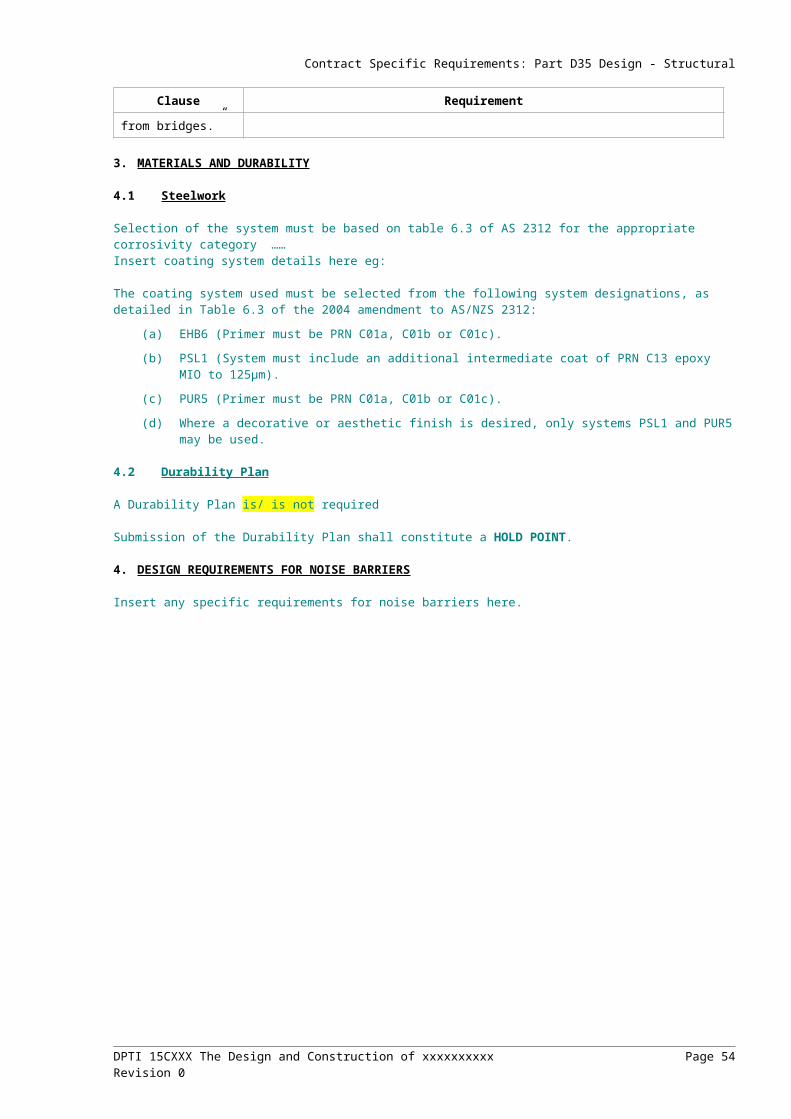
Contract Specific Requirements: Part CH20 Provision for Traffic
PART CH20 PROVISION FOR TRAFFIC
For example Contract Specific Requirements for relevant Parts in Division CH – Construction and Handover, refer to:
Division CH Contract Specific Requirements (.docx)
DPTI 15CXXX The Design and Construction of xxxxxxxxxx Page 54Revision 0

DPTI 15CXXX The Design and Construction of xxxxxxxxxx Page 55Revision 0

DPTI 15CXXX The Design and Construction of xxxxxxxxxx Page 56Revision 0