noise control on construction and open sites · pdf filenoise control on construction and open...
TRANSCRIPT
BRITISH STANDARD BS 5228-4:1992Incorporating Amendment No.1
Noise control on construction and open sites —
Part 4: Code of practice for noise and vibration control applicable to piling operations
Licensed copy:DORSET ENGINEERING, 24/08/2007, Uncontrolled Copy, © BSI

BS 5228-4:1992
This British Standard, having been prepared under the direction of the Basic Data and performance Criteria for Civil Engineering and Building Structures Standards Policy Committee, was published under the authority of the Standards Board and comes into effect on1 May 1992
© BSI 02-1999
First published January 1986Second edition May 1992
The following BSI references relate to the work on this standard:Committee reference BDB/5Draft for comment 90/14249 DC
ISBN 0 580 20381 6
Committees responsible for this British Standard
The preparation of this British Standard was entrusted by the Basic Data and Performance Criteria for Civil Engineering and Building Structures Standards Policy Committee (BDB/-) to Technical Committee BDB/5, upon which the following bodies were represented:
Arboricultural Association Association of County CouncilsAssociation of District Councils Association of Metropolitan AuthoritiesBuilding Employers Confederation Construction Health and Safety GroupDepartment of the Environment (Property Federation of Civil Engineering
Services Agency) ContractorsFederation of Piling Specialists Health and Safety ExecutiveIncorporated Association of Architects and Institute of Building Control
SurveyorsInstitute of Clerks of Works of Great Britain Institution of Civil Engineers
IncorporatedInstitution of Environmental Health Officers Institution of Structural EngineersLandscape Institute National Council of Building Material
ProducersRoyal Institute of British Architects Royal Institution of Chartered SurveyorsScottish Office (Building Directorate) Society of Chief Architects of Local
AuthoritiesTrades Union Congress
The following bodies were also represented in the drafting of the standard, through subcommittees and panels:
Association of Consulting Engineers British Aggregate Construction MaterialsIndustries
British Coal Corporation British Compressed Air SocietyConcrete SocietyConstruction Plant (Hire Association) Department of the Environment (Building
Research Establishment)Federation of Dredging Contractors Institution of Highways and
TransportationSand and Gravel Association Limited Society of Motor Manufacturers and
Traders Limited
Amendments issued since publication
Amd. No. Date Comments
7787 July 1993 Indicated by a sideline in the margin
Licensed copy:DORSET ENGINEERING, 24/08/2007, Uncontrolled Copy, © BSI
BS 5228-4:1992
© BSI 02-1999 i
Contents
PageCommittees responsible Inside front coverForeword iii
Section 1. General0 Introduction 11 Scope 12 Definitions 13 Legislative background 14 Guidance notes on legislation 2 5 Project supervision 4
Section 2. Noise6 Factors to be considered when setting noise control targets 77 Practical measures to reduce site noise 18
Section 3. Vibration8 Factors to be considered when setting vibration control targets 229 Practical measures to reduce vibration 2610 Measurement 28
Appendix A Description of vibration 31Appendix B Prediction of vibration levels 33Appendix C Measured vibration levels 34Appendix D Examples of record sheets 60Appendix E Bibliography 62
Figure 1 — Procedures to control construction noise and/orvibration under the Control of Pollution Act 1974 6Figure 2 — Piling and kindred ground treatment systems 21Figure 3 — Orientation of vibration transducers 24Figure 4 — Site measurements sheet 60Figure 5 — Vibration data summary sheet 61
Table 1 — Sound level data on piling 8Table 2 — Vibration effects on different subjects: the parametersto measure and the ranges of sensitivity of apparatus to use 30Table 3 — Summary of case history data on vibration levels measuredduring impact bored piling (tripod) 36Table 4 — Summary of case history data on vibration levels measuredduring driven cast-in-place piling (drop hammer) 39Table 5 — Summary of case history data on vibration levels measuredduring dynamic consolidation 41Table 6 — Summary of case history data on vibration levels measuredduring vibroflotation/vibroreplacement 44Table 7 — Summary of case history data on vibration levels measuredduring the use of casing vibrators 48Table 8 — Summary of case history data on vibration levels measuredduring rotary bored piling (including casing dollies) 50Table 9 — Summary of case history data on vibration levels measuredduring tripod bored piling 51Table 10 — Summary of case history data on vibration levels measured during driven sheet steel piling 52Table 11 — Summary of case history data on vibration levels measured during driving of bearing piles 54
Licensed copy:DORSET ENGINEERING, 24/08/2007, Uncontrolled Copy, © BSI

BS 5228-4:1992
ii © BSI 02-1999
PageTable 12 — Summary of case history data on vibration levels measured during use of vibratory pile drivers 57Table 13 — Summary of miscellaneous case history data on vibration levels measured during piling and kindred operations 59
Publication(s) referred to Inside back cover
Licensed copy:DORSET ENGINEERING, 24/08/2007, Uncontrolled Copy, © BSI

BS 5228-4:1992
© BSI 02-1999 iii
Foreword
This part of BS 5228, Which has been prepared under the direction of the Basic Data and Performance Criteria for Civil Engineering and Building Structures Standards Policy Committee, covers the control of noise and vibration from piling sites, and is a revision of BS 5228-4:1986, which is withdrawn.The standard refers to the need for the protection of persons living and working in the vicinity of such sites and those working on the sites from noise and vibration. It recommends procedures for noise and vibration control in respect of piling operations and aims to assist architects, contractors and site operatives, designers, developers, engineers, local authority environmental health officers and planners, regarding the control of noise and vibration.Vibration can cause disturbance to processes and activities in neighbouring buildings, and in certain circumstances can cause or contribute to building damage.Vibration can be the cause of serious disturbance and inconvenience to anyone exposed to it. The Control of Pollution Act 1974, the Environmental Protection Act 1990 and, in Northern Ireland, the Pollution Control and Local Government (Northern Ireland) Order 1978, which define “noise” as including “vibration” (Section 73(1) of the 1974 Act, Section 79(7) of the 1990 Act and Article 53(1) of the 1978 Order), contain provisions for the abatement of nuisances caused by noise and vibration.It should be noted that BS 6472 covers the human response to vibration in structures and BS 7385-1 covers the measurement and evaluation of structural vibration. An item dealing with the vibratory loading of structures is being processed within ISO/TC 98/SC 2 “Safety of Structures”. This is being monitored by BSI.BS 5228 consists of the following Parts:
— Part 1: Code of practice for basic information and procedures for noise control;— Part 2: Guide to noise control legislation for construction and demolition, including road construction and maintenance;— Part 3: Code of practice for noise control applicable to surface coal extraction by opencast methods;— Part 4: Code of practice for noise and vibration control applicable to piling operations.
BS 5228-1 is common to all the types of work covered by the other Parts of BS 5228, which should be read in conjunction with Part 1.Other Parts will be published in due course as and when required by industry.Attention is drawn to the Control of Pollution Act 1974 (Part III) (Noise), the Environmental Protection Act 1990 (Part III) (Statutory Nuisances and Clean Air), the Health and Safety at Work etc. Act 1974 (in Northern Ireland, the Pollution Control and Local Government (Northern Ireland) Order 1978 and the Health and Safety at Work (Northern Ireland) Order 1978), and to the Noise at Work Regulations 1989, Statutory Instrument 1989 No. 1790.A British Standard does not purport to include all the necessary provisions of a contract. Users of British Standards are responsible for their correct application.
Compliance with a British Standard does not of itself confer immunity from legal obligations.
Summary of pagesThis document comprises a front cover, an inside front cover, pages i to iv, pages 1 to 62, an inside back cover and a back cover.This standard has been updated (see copyright date) and may have had amendments incorporated. This will be indicated in the amendment table on the inside front cover.
Licensed copy:DORSET ENGINEERING, 24/08/2007, Uncontrolled Copy, © BSI

iv blankLicensed copy:DORSET ENGINEERING, 24/08/2007, Uncontrolled Copy, © BSI

BS 5228-4:1992
© BSI 02-1999 1
Section 1. General
0 IntroductionThis Part of BS 5228 is concerned with all works associated with piling operations on sites where temporary or permanent foundation or ground stability requirements are to be met by the installation of piles by any of the recognized techniques (see 7.2). In common with other mechanized construction activities, piling works pose different problems of noise and vibration control from those associated with most types of factory-based industry for the following reasons:
a) they are mainly carried out in the open;b) they are of temporary duration, although they may cause great disturbance while they last;c) the noise and vibration they cause arise from many different activities and kinds of plant, and their intensity and character may vary greatly at different phases of the work;d) the sites cannot be excluded by planning control, as factories can, from areas that are sensitive to noise.
Increased mechanization has meant the use of more powerful and potentially noisier machines. It is now widely recognized that noise levels that can be generated are unacceptable in many instances and that reductions are desirable for the benefit of both the industry and the public. Piling works frequently form one of the noisier aspects of construction. The trend towards medium and high rise structures, particularly in urban areas, coupled with the necessity to develop land which was hitherto regarded as unfit to support structures, has led to increasing use of piled foundations. Piling is usually one of the first activities to be carried out on site, and special precautions should be taken to mitigate the disturbance created, particularly in sensitive areas.If a site upon which construction or demolition work will be carried out involves an existing operational railway, special features that are significant in relation to noise and vibration control have to be taken into account. Advice should be sought in such cases from the appropriate railway authorities.Because of the variable nature of vibration transmission characteristic of soils, rocks and structure, the prediction of vibration levels is a less precise science than the corresponding prediction of air-borne noise levels. Whilst data obtained from various sources are included for illustrative purposes, any predictions based thereon for specific circumstances should ideally be verified by appropriate field measurements.
1 ScopeThis part of BS 5228 supplements the information given in BS 5228-1, with information especially relevant to piling works. It sets out recommendations for noise and vibration control measures which can be adopted to ensure good practice and enable piling to be carried out economically with as little disturbance to the community as is practicable.Section 2 contains recommendations relating to noise control. Section 3 contains recommendations for the mitigating of the effects of ground-borne vibration.NOTE 1 This Part of BS 5228 should be read in conjunction with BS 5228-1.NOTE 2 The titles of the publications referred to in this standard are listed on the inside back cover.
2 DefinitionsFor the purposes of this Part of BS 5228, the definitions given in BS 5228-1 apply together with the following.
2.1 amplification factor
the motion measured at a given point (usually on the structure) divided, by the motion measured at a reference point (usually at the base of the structure or on the foundation)
2.2 peak particle velocity (p.p.v.)
the maximum value of particle velocity obtained during a given interval
2.3 piling
the installation of bored and driven piles and the effecting of ground treatments by vibratory, dynamic and other methods of ground stabilization
3 Legislative backgroundAttention is drawn to the following legislation, current at the date of publication of this Part of BS 5228.
a) Control of Noise (Appeals) (Scotland) Regulations 1983.b) Control of Noise (Appeals) Regulations 1975.c) Statutory Nuisance (Appeals) Regulations (as amended) 1990.d) Control of Noise (Appeals) Regulations (Northern Ireland) 1978.e) Control of Pollution Act 1974.f) Environmental Protection Act 1990.g) Health and Safety at Work etc. Act 1974.
Licensed copy:DORSET ENGINEERING, 24/08/2007, Uncontrolled Copy, © BSI

BS 5228-4:1992
2 © BSI 02-1999
h) Health and Safety at Work (Northern Ireland) Order 1978.i) Land Compensation Act 1973.j) Land Compensation (Scotland) Act 1973 (in Northern Ireland, the Land Acquisition and Compensation (Northern Ireland) Order, 1973).k) Noise Insulation Regulations 1975 (in Scotland, the Noise Insulation (Scotland) Regulations 1975).l) Pollution Control and Local Government (Northern Ireland) Order 1978.m) Public Health Act 1961.
The Control of Pollution Act 1974, the Environmental Protection Act 1990 and, in Northern Ireland, the Pollution Control and Local Government (Northern Ireland) Order 1978 SI 1049, which define noise as including vibration (Section 73 (1) of the 1974 Act, Section 79(7) of the 1990 Act and Article 53(1) of the 1978 Order) contain provisions for the abatement or cessation of nuisances caused by noise and vibration.
4 Guidance notes on legislation4.1 General
This information on procedures is given for guidance purposes only and attention is drawn to the relevant Acts.
4.2 The Control of Pollution Act 1974
The Control of Pollution Act 1974 gives local authorities powers for controlling noise and/or vibration from construction sites and other similar works. These powers may be exercised either before works start or after they have started. In Northern Ireland, similar provision is made in the Pollution Control and Local Government (Northern Ireland) Order 1978. Contractors, or persons arranging for works to be carried out, also have the opportunity to take the initiative and ask local authorities to make their noise and/or vibration requirements known. Because of an emphasis upon getting noise and/or vibration questions settled before work starts, implications exist for traditional tender and contract procedures (see 4.5).
4.3 Notices under Section 60 of the Control of Pollution Act 1974
Section 60 enables a local authority, in whose area work is going to be carried out, or is being carried out, to serve a notice of its requirements for the control of site noise and/or vibration on the person who appears to the local authority to be carrying out the works and on such other persons appearing to the local authority to be responsible for, or to have control over, the carrying out of the works.
This notice can perform the following.a) Specify the plant or machinery that is or is not to be used. However, before specifying any particular methods or plant or machinery a local authority has to consider the desirability, in the interests of the recipient of the notice in question, of specifying other methods or plant or machinery that will be substantially as effective in minimizing noise and/or vibration and that will be more acceptable to the recipient.b) Specify the hours during which the construction work can be carried out.c) Specify the level of noise and/or vibration that can be emitted from the premises in question or at any specified point on those premises or that can be emitted during the specified hours.d) Provide for any change of circumstances. An example of such a provision might be that if ground conditions change and do not allow the present method of working to be continued then alternative methods of working should be discussed with the local authority.
In serving such a notice a local authority takes account of:
1) the relevant provisions of any code of practice issued and/or approved under Part III of the Control of Pollution Act 1974;2) the need for ensuring that the best practicable means are employed to minimize noise and/or vibration;3) other methods, plant or machinery that might be equally effective in minimizing noise and/or vibration, and be more acceptable to the recipient of the notice;4) the need to protect people in the neighbourhood of the site from the effects of noise and/or vibration.
Licensed copy:DORSET ENGINEERING, 24/08/2007, Uncontrolled Copy, © BSI

BS 5228-4:1992
© BSI 02-1999 3
A person served with such a notice can appeal to a magistrates’ court or in Scotland to the Sheriff or in Northern Ireland to a court of summary jurisdiction, within 21 days from the date of serving of the notice. Normally the notice is not suspended pending an appeal unless it requires some expenditure on works and/or the noise or vibration in question arises or would arise in the course of the performance of a duty imposed by law on the appellant. The regulations governing appeals (the Control of Noise (Appeals) Regulations 1975; in Northern Ireland, the Control of Noise (Appeals) Regulations (Northern Ireland) 1978; and in Scotland, the Control of Noise (Appeals) (Scotland) Regulations 1983) also give local authorities discretion not to suspend a notice even when one or other of these conditions is met, if the noise and/or vibration is injurious to health, or is of such limited duration that a suspension would render the notice of no practical effect; or if the expenditure necessary on works is trivial compared to the public benefit expected.
4.4 Consents under Section 61 of the Control of Pollution Act 1974
This subclause concerns the procedure adopted when a contractor (or developer) takes the initiative and approaches the local authority to ascertain its noise and/or vibration requirements before construction work starts (see also 4.3).It is not mandatory for applications for consents to be made, but it will often be in the interest of a contractor or an employer or their agents to apply for a consent, because once a consent has been granted a local authority cannot take action under Section 58 or Section 60 of the Control of Pollution Act 1974 or Section 80 of the Environmental Protection Act 1990, so long as the consent remains in force and the contractor complies with its terms. Compliance with a consent does not, however, exempt the person holding that consent against action by a private individual under Section 59 of the 1974 Act, under Section 82 of the 1990 Act, or under common law.It is essential that an application for a consent is made at the same time as, or later than, any request for approval under Building Regulations or for a warrant under Section 6 of the Building (Scotland) Act 1959, when this is relevant. Subject to this constraint, there are obvious advantages in making any application at the earliest possible date. There may be advantages in having informal discussions before formal applications are made.
It is essential that an applicant for a consent gives the local authority as much detail as possible about the construction work to which the application relates and about the method or methods by which the work is to be carried out. It is also essential that information be given about the steps that will be taken to minimize noise and/or vibration resulting from the construction work.Provided that a local authority is satisfied that proposals (accompanying an application) for the minimizing of noise and/or vibration are adequate (and in deciding this it may have regard, among other things, to the provisions of this standard), it will give its consent to the application. It can however attach conditions to the consent, or limit or qualify the consent, to allow for any change in circumstances and to limit the duration of the consent. If a local authority fails to give its consent within 28 days of the lodging of an application, or if it attaches any conditions or qualification to the consent that are considered unnecessary or unreasonable, the applicant concerned can appeal to a magistrates’ court or in Scotland to the Sheriff or in Northern Ireland to a court of summary jurisdiction, within 21 days from the end of that period.When a consent has been given and the construction work is to be carried out by a person other than the applicant for the consent, it is essential that the applicant takes all reasonable steps to bring the terms of consent to the notice of that other person; failure to do so or failure to observe the terms of a consent are offences under the Act.
4.5 Contractual procedures
It is likely to be to the advantage of a developer or contractor, or an employer or his agent, who intends to carry out construction work, to take the initiative and apply to the local authority for consents under the Control of Pollution Act. This will have implications for traditional tender and contract procedures because the local authority’s noiseand/or vibration requirements may well affect both the tender and contract price. It is therefore preferable that the local authority’s requirements are made known before tenders are submitted. The best way of achieving this is for the person for whom the work is to be carried out to make the application to the local authority for a consent, before inviting tenders. As much detailed information as possible should be given concerning the methods by which the construction work is to be carried out, and concerning also the proposed noise abatement and/or vibration control measures to enable the local authority to give a consent (see also 4.4).
Licensed copy:DORSET ENGINEERING, 24/08/2007, Uncontrolled Copy, © BSI

BS 5228-4:1992
4 © BSI 02-1999
When a person for whom construction work is to be carried out has sought and obtained consent from the local authority, the local authority’s requirements should be incorporated in the tender documents so that tenderers do not base their tenders on the use of unacceptable work methods and plant.As far as possible, a contractor should be allowed freedom of choice regarding plant and methods to be used but a local authority can, in consultation with the recipient of a consent, specify the type of plant or methods to be used with its consent. In addition to any approach made by a person responsible for construction work, a tenderer may also wish to apply to a local authority in order either to seek consent for the use of methods or plant in place of those specified in an earlier consent (or notice), or to satisfy himself that the detailed methods and plant that he had planned to use meet the conditions laid down.
4.6 Emergencies
In the event of any emergency or unforeseen circumstances arising that cause safety to be put at risk, it is important that every effort should be made to ensure that the work in question is completed as quickly and as quietly as possible and with minimum practical disturbance to people living or working nearby. The local authority should be informed as soon as possible, should it be found necessary to exceed permitted noise and/or vibration limits because of an emergency.
4.7 Flow diagram
The procedures available under the Control of Pollution Act 1974 for the control of construction noise and/or vibration are illustrated by the flow diagram shown in Figure 1.
4.8 Land Compensation Act 1973 (as amended), Highways Act 1980 and Land Compensation (Scotland) Act 1973
The Noise Insulation Regulations 1975 and Noise Insulation (Scotland) Regulation 1975, made under the powers contained respectively in the Land Compensation Act 1973 and the Land Compensation (Scotland) Act 1973, allow a highway authority to provide insulation for dwellings and other buildings used for residential purposes by means of double glazing and special ventilation when highway works are expected to cause serious noise effects for a substantial period of time. The 1973 Acts also contain provisions that enable a highway authority to pay the reasonable expenses of residents who, with the agreement of the authority, have to find suitable alternative accommodation for the period during which construction work makes continued occupation of an adjacent dwelling impracticable.The Highways Act 1980 and the Land Compensation (Scotland) Act 1973 enable highway authorities to acquire land by agreement when its enjoyment is seriously affected by works of highway construction or improvement. In addition, these Acts give the highway authority power to carry out works, for example the installation of noise barriers, to mitigate the adverse effects of works of construction or improvement on the surroundings of a highway.
5 Project supervision5.1 Project programme
Piling programmes should be arranged so as to control the amount of disturbance in noise and vibration sensitive areas at times that are considered to be of greatest sensitivity. If piling works are in progress on a site at the same time as other works of construction and demolition that themselves may generate significant noise and vibration, the working programme should be phased so as to prevent unacceptable disturbance at any time.
Licensed copy:DORSET ENGINEERING, 24/08/2007, Uncontrolled Copy, © BSI

BS 5228-4:1992
© BSI 02-1999 5
5.2 Piling subcontracts: consents and notices
When piling works are to form a subcontract to the main construction and demolition works on a site, copies of noise and/or vibration consents and details of other noise and/or vibration restrictions should be included in the tender documents for the piling subcontract. Any such noise and/or vibration restrictions, limitations on hours of work, etc., may be at variance with conditions with which the piling tenderer may otherwise be expected to comply. Provision should therefore be made for further consultations with the local authority that could in turn lead to a special consent or variation in restrictions for the duration of the piling works.During such a consultation the planner, developer, architect and engineer, as well as the local authority, should be made aware of the proposed method of working of the piling subcontractor, who in turn should have evaluated any practicable and more acceptable alternatives that would economically achieve, in the given ground conditions, equivalent structural results. Information relating to the mechanical equipment and plant to be used (see BS 5228-1) should be supplied in support of the proposed method of working. An indication of the intended programme of works should be given, but the piling subcontractor will wish to retain as much flexibility as possible in order to combat unexpected ground conditions or other problems, and it should be recognized that substantial deviations from a detailed programme of works could be made in practice. Due attention should be paid to safe working practices and to emergency procedures.The developer, as the person ultimately responsible for a project, will need to instigate a check that the proposals suggested by those tendering for piling works are likely to be acceptable to the local authority.
Licensed copy:DORSET ENGINEERING, 24/08/2007, Uncontrolled Copy, © BSI

BS
5228-4:1992
6©
BS
I 02-1999 Figure 1 — Procedures to control construction noise and/or vibration under the Control of Pollution Act 1974
Licensed copy:DORSET ENGINEERING, 24/08/2007, Uncontrolled Copy, © BSI

BS 5228-4:1992
© BSI 02-1999 7
Section 2. Noise
6 Factors to be considered when setting noise control targets6.1 Selection of piling method
6.1.1 The selection of a method to be used for the installation of piles will depend on many factors, some of which are outlined in 6.1.2 (see 7.2 for types of piling).6.1.2 It should be remembered that a decision regarding the type of pile to be used on a site will normally be governed by such criteria as loads to be carried, strata to be penetrated and the economics of the system, for example the time it will take to complete the installation and other associated operations such as soil removal.6.1.3 It may not be possible for technical reasons to replace a noisy process by one of the “quieter piling” alternatives. Even if it is possible, the adoption of a quieter method may prolong the piling operation; the net result being that the overall disturbance to the community, not only that caused by noise, will not necessarily be reduced.6.1.4 Examples of typical noise levels associated with the different methods of piling are given in Table 1 which is an extension to the data given in Table 8 of BS 5228-1:1984.
6.2 Types of noise
On typical piling sites the major sources of noise are essentially mobile and the noise received at any control points will, therefore, vary from day to day as work proceeds.The type of noise associated with piling works depends on the method of piling employed. For example, pile driving using a drop hammer results in a well defined, impulsive type of noise. Air and diesel hammers also produce impulsive noise although their striking rates can be much higher than with drop hammers. With auger-bored piling the impulsive characteristic is virtually absent. With bored or jacked piling methods the resultant noise is steady.Highly impulsive noise is generally less acceptable than steady noise. However, other characteristics of the noise source play an important part in determining the acceptability of piling noise, e.g. cable slap, screeching of pulleys and guides and ringing of piles.
6.3 Duration of piling works
The duration of piling work is usually short in relation to the length of construction work as a whole, and the amount of time spent working near to noise-sensitive areas can represent only a part of the piling period.
6.4 Hours of working
When a local authority intends to control noise by imposing restrictions on working hours it should have regard to the specialized nature of some piling works, which may necessitate a longer working day.A local authority should also bear in mind the acceptable hours for the residents and occupiers of a particular area.
6.5 Methods of monitoring and control
Whatever method is appropriate for the specifying of a noise target, there should be agreement between the piling contractor concerned and the controlling authority.It is essential that a noise target is appropriate to the type of noise, and is practical and enforceable. It should adequately protect the community but allow work to proceed as near normally as possible.Steady noise levels should normally be expressed in terms of the LAeq over a period of several hours or for a working day. Impulsive noise levels cannot always be controlled effectively using this measure alone. The specification of a higher short term limit is often found useful. This can be achieved by specifying a short period LAeq or the one percentile exceedance level LA01 over one driving cycle. Where LA01 is specified the F time weighting should be used and measurements should be made with a sampling rate of at least five samples per second. Noise limits should not be set in terms of LpA,max. when the noise is impulsive.The difference between limits set in terms of LA01 and LAeq will depend on the striking rate of the pile driver.Those who wish to use the data for LAeq in Table 1 to estimate the corresponding value of LA01 should note the following approximate relationships [all measurements in dB(A)]:
a) LA01 for pile drivers such as drop hammers with a slow striking rate; and
≈ LAeq + 11
b) LA01 for air hammers with a fast striking rate.≈ LAeq + 5
Licensed copy:DORSET ENGINEERING, 24/08/2007, Uncontrolled Copy, © BSI

BS
5228-4:1992
8©
BS
I 02-1999
Table 1 — Sound level data on piling
Ref no.a
Pile Method Energy, power rating Dolly Sound power level LWA
Soil Cycle time
On-time
Activity equivalent continuous
sound pressure level LAeq at 10 m (1 cycle)
Depth Width
m m dB % dB
SHEET STEEL PILING
50 12 0.4Double acting diesel hammer
3 790 kgf·m Steel on fibrous material
135 — — 100 107
51 16 500 kgf·m Not known 140 — 100 112
52 12 0.4 Double acting air hammer
560 kgf·m Steel on fibrous material
134 — — 100 106
53 12 0.4 Hydraulic vibratory driver
20.7 kg·m eccentric moment; 26 Hz
None 118 Sand and gravel — 100 90
54 8 0.508Air hammer
415 kgf·m None 131 Sandy clay overlying boulder clay
— 100 103
55 8 0.508 415 kgf·m None 134 Sandy clay overlying boulder clay
— 100 106
56 8 0.508 Drop hammer (hammer and pile enclosed acoustically)
3 t 150 mm greenheart timber plus rope
94 Sandy clay overlying boulder clay
— 100 66
57 8 0.508 3 t 150 mm greenheart timber plus rope
98 Sandy clay overlying boulder clay
— 100 70
a See reference numbers 1 to 49, in Table 8 of BS 5228-1:1984 for further information concerning sound level data on piling.
Licensed copy:DORSET ENGINEERING, 24/08/2007, Uncontrolled Copy, © BSI

BS
5228-4:1992
© B
SI 02-1999
9
Table 1 — Sound level data on piling
Ref no.
Pile Method Energy, power rating Dolly Sound power level LWA
Soil Cycle time
On-time
Activity equivalent continuous
sound pressure
level LAeq at 10 m (1 cycle)
Depth Width
m m dB % dB
58 10 (4 m exposed)
0.96 Double acting air impulse hammer
15 kN·m Air cushion 111 — — 100 83
59 15 (5 m exposed)
1.05 Hydraulic hammer, enclosed acoustically
60 kN·m Steel on fibrous material
121 Gravel overlying stiff clay
— 100 93
60 15 1.05 Hydraulic drop hammer, enclosed acoustically
60 kN·m Steel on fibrous material
113 Gravel overlying stiff clay
— 100 85
TUBULAR CASING
61 23 1.07 dia. Double acting 6 219 kgf·m Not known 122 Silt overlying chalk — 100 94
62 23 1.07 dia. diesel hammer 16 000 kgf·m Not known 132 Silt overlying chalk — 100 104
TUBULAR STEEL CASING/PILE CAST IN PLACE
63(a) 13 0.35 dia. Drop hammer 3.3 t, 1.2 m drop Resilient composite pad
130 Estuarial alluvia 20 min 20 95
9763(b) 13 0.35 dia. 3.3 t, 1.2 m drop Resilient composite pad
126 Estuarial alluvia 20 min 30 93
63(c) 13 0.35 dia. Drop hammer, extracting casing
3.3 t Resilient composite pad
120 Estuarial alluvia 20 min 10 82
64(a) 14 0.4 dia.
Drop hammer
4 t, 1.2 m drop Resilient composite pad
132 Dense sand 45 min 40 100
10064(b) 14 0.4 dia. 4 t, 1.2 m drop Resilient composite pad
125 Dense sand 45 min 20 90
64(c) 14 0.4 dia. Drop hammer, extracting casing
4 t Resilient composite pad
118 Dense sand 45 min 5 77
Licensed copy:DORSET ENGINEERING, 24/08/2007, Uncontrolled Copy, © BSI

BS
5228-4:1992
10©
BS
I 02-1999
Table 1 — Sound level data on piling
Ref no.
Pile Method Energy, power rating Dolly Sound power level LWA
Soil Cycle time
On-time
Activity equivalent continuous
sound pressure
level LAeq at 10 m
(1 cycle)
Depth Width
m m dB % dB
65(a) 8 0.35 dia.Drop hammer, partially enclosed acoustically
3.3 t, 1.2 m drop Resilient composite pad
117 Silt/peat/shale/sandstone
25 min 15 81
9165(b) 8 0.35 dia. 3.3 t, 1.2 m drop Resilient composite pad
122 Silt/peat/shale/sandstone
25 min 35 89
65(c) 8 0.35 dia. Drop hammer, partially enclosed acoustically, extracting casing
3.3 t, 1.2 m drop Resilient composite pad
121 Silt/peat/shale/sandstone
25 min 8 82
66(a) 8 0.4 dia.Drop hammer, partially enclosed acoustically
4 t, 1.6 m drop None 129 Stiff to hard sandy clay
30 min 35 96
9766(b) 8 0.4 dia. 4 t, 1.6 m drop None 125 Stiff to hard
sandy clay30 min 30 92
67(a) 5 0.45 dia.
Internal drop hammer
3 t, 4 m drop Dry mix aggregate plug
113 Made ground overlying clay
40 min 50 82
8667(b) 5 0.45 dia. 3 t, 4 m drop Dry mix
aggregate plug115 Made ground
overlying clay40 min 50 84
68(a) 14 0.4 dia. 3 t, 4 m drop Dry mix aggregate plug
111 Ballast — 50 80
8468(b) 14 0.4 dia. 3 t, 4 m drop Dry mix
aggregate plug116 Ballast — 25 82
Licensed copy:DORSET ENGINEERING, 24/08/2007, Uncontrolled Copy, © BSI

BS
5228-4:1992
© B
SI 02-1999
11
Table 1 — Sound level data on piling
Ref no.a
Pile Method Energy, power rating
Dolly Sound power level LWA
Soil Cycle time
On-time
Activity equivalent continuous
sound pressure level LAeq at 10 m
(1 cycle)
Depth Width
m m dB % dB
IMPACT BORED/PILE CAST IN PLACE
69(a) 20 0.5 dia. Tripod winch 20 kW None 106 Fill/ballast/stiff clay 6 h 30 73
8369(b) 20 0.5 dia. 20 kW None 108 Fill/ballast/stiff clay 6 h 60 78
69(c) 20 0.5 dia. Tripod winch, driving casing
3/4 t, 1 m drop Steel 118 Fill/ballast/stiff clay 6 h 2.5 74
69(d) 20 0.5 dia. 3/4 t, 1 m drop Steel 122 Fill/ballast/stiff clay 6 h 2.5 78
70(a) 25 0.6 dia.
Tripod winch
20 kW None 108 Fill/sand/ballast/stiff clay
10 h 30 75
88
70(b) 25 0.6 dia. 20 kW None 113 Fill/sand/ballast/stiff clay
10 h 60 83
70(c) 25 0.6 dia.Tripod winch, driving casing
3/4 t, 1 m drop 127 Fill/sand/ballast/stiff clay
10 h 2 82
70(d) 25 0.6 dia. 3/4 t, 1 m drop Steel 129 Fill/sand/ballast/stiff clay
10 h 2 84
H SECTION STEEL PILING
71 22.5 0.31 × 0.31 × 0.11
Double acting diesel hammer
3 703 kgf·m Steel on fibrous material
127 Sand and silt overlying stiff clay
— 100 99
72 — 0.35 × 0.37 × 0.089
Diesel hammer 6 219 kgf·m Not known 122 Rock fill — 100 94
73 75 0.3 × 0.3 Hydraulic drop hammer, enclosed acoustically
36 kN·m Hardwood 113 Chalk — 100 85
74 75 0.3 × 0.3 36 kN·m Hardwood 116 Chalk — 100 88
75 75 0.3 × 0.3 Hydraulic drop hammer 84 kN·m Steel on fibrous material
124 Chalk — 100 96
a See reference numbers 1 to 49, in Table 8 of BS 5228-1:1984 for further information concerning sound level data on piling.
Licensed copy:DORSET ENGINEERING, 24/08/2007, Uncontrolled Copy, © BSI

BS
5228-4:1992
12©
BS
I 02-1999
Table 1 — Sound level data on piling
Ref no.
Pile Method Energy, power rating Dolly Sound power level LWA
Soil Cycle time
On-time
Activity equivalent continuous
sound pressure level LAeq at 10 m (1 cycle)
Depth Width
m m dB % dB
PRECAST CONCRETE PILES
76 — — Drop hammer 5 t, 0.75 m drop Not known 114 Fill — 100 86
77 50 0.29 × 0.29 square section modular (joined)
Hydraulic drop hammer, enclosed acoustically
60 kN·m Hardwood 107 Chalk — 100 79
78 50 60 kN·m Hardwood 111 Chalk — 100 83
79 20 0.275 ×0.275 square section modular (joined)
Hydraulic hammer
3 t, 0.3 m drop Hardwood 111 Stiff clay overlying mudstone
— 100 83
80 20 3 t, 0.3 m drop Hardwood 119 Stiff clay overlying mudstone
— 100 91
Licensed copy:DORSET ENGINEERING, 24/08/2007, Uncontrolled Copy, © BSI

BS
5228-4:1992
© B
SI 02-1999
13
Table 1 — Sound level data on piling
Ref no.
Pile Method Energy, power rating Dolly Sound power level LWA
Soil Cycle time
On-time
Activity equivalent continuous
sound pressure level LAeq at 10 m
(1 cycle)
Depth Width
m m dB % dB
81 10 0.275 ×0.275 square section modular (joined)
Hydraulic hammer, partially enclosed acoustically
4 t, 0.3 m drop Hardwood 109 Clay/gravel overlying mudstone
— 100 81
82 10 4 t, 0.3 m drop Hardwood 106 Clay/gravel overlying mudstone
— 100 78
83 17 0.285 ×0.285 square section modular (joined)
Drop hammer 5 t, 1 m drop Wood 114 Silt/sand/gravel 55 min 80 85
84 20 0.08 m2 hexagonal section modular (joined)
Drop hammer, hanging leaders: soft driving
4 t, 0.6 m drop Wood 114 Alluvium — 100 86
85 20 0.08 m2 hexagonal section modular (joined)
Drop hammer, hanging leaders: medium/hard driving
4 t, 0.75 m drop Wood 121 Stiff clays and gravels
— 100 93
Licensed copy:DORSET ENGINEERING, 24/08/2007, Uncontrolled Copy, © BSI

BS
5228-4:1992
14©
BS
I 02-1999
Table 1 — Sound level data on piling
Ref no.
Pile Method Energy, power rating Dolly Sound power level LWA
Soil Cycle time
On-time
Activity equivalent continuous
sound pressure
level LAeq at 10 m (1 cycle)
Depth Width
m m dB % dB
86 20 0.406 dia. modular shell Drop hammer driving
on mandrel/pile cast in place
5 t, 0.75 m drop Wood/sisal 114 Fill overlying chalk
41 min 30 82
87 28 0.444 dia. modular shell
6 t, 1 m drop Wood 121 Sand/clay/chalk 57 min 30 89
BORED PILING/PILE CAST IN PLACE
88 10 0.45 dia. Crane-mounted auger: donkey engine in acoustic enclosure
65 kW None 108 Fill overlying stiff clay
45 min 100 80
89(a) 25 0.6 dia. 90 kW None 110 Sand/gravel/stiff clay
90 min 85 81
8589(b) 7 0.6 dia. Driving temporary
casing to support upper strata in prebored hole by drop hammer
2.5 t, 0.6 m drop Steel 128 Sand/gravel/stiff clay
90 min 1.5 82
90 15 0.45 dia. Lorry-mounted auger: donkey engine in acoustic enclosure
90 kW None 109 Sand/gravel/clay 55 min 100 81
91 20 0.6 dia. 90 kW None 113 Fill/clay 75 min 100 85
92(a) 25 0.9 dia. Crane-mounted auger 90 kW None 114 Fill/clay 3 h 95 868792(b) 25 0.9 dia. Crane-mounted auger:
kelly bar clanging90 kW None 122 Fill/clay 3 h 3 79
93 30 1.05 dia. Crane-mounted auger 120 kW None 117 Ballast/clay 5 h 100 89
Licensed copy:DORSET ENGINEERING, 24/08/2007, Uncontrolled Copy, © BSI

BS
5228-4:1992
© B
SI 02-1999
15
Table 1 — Sound level data on piling
Ref no. Pile Method Energy, power rating
Dolly Sound power level LWA
Soil Cycle time
On-time
Activity equivalent continuous
sound pressure
level LAeq at 10 m (1 cycle)
Depth Width
m m dB % dB
94(a) 24 2.1 dia. Crane-mounted auger and drilling bucket: pile bored under bentonite
110 kW None 112 Alluvia/sands/clay 2 days 50 8182
94(b) 24 2.1 dia. Crane-mounted auger and drilling bucket: kelly bar clanging
110 kW None 121 Alluvia/sands/clay 2 days 2 76
95 40 1.2 dia. Crane-mounted auger and drilling bucket: pile bored under bentonite
120 kW None 117 Sand/boulder clay/marl
2 days 50 86
96 20 0.9 dia. Lorry-mounted auger 110 kW None 115 Fill/sand/gravel/clay 3 h 100 87
97 20 1.2 dia. 110 kW None 112 Fill/ballast/clay 6 h 100 84
CONTINUOUS FLIGHT AUGER INJECTED PILING
98 11 0.45 dia. Crane-mounted leaders with continuous flight auger; cement grout injected through hollow stem of auger.Engine/power pack partially enclosed acoustically
90 kW None 111 Alluvium 30 min 50 80
99 15 0.35 dia. 90 kW None 108 Sand and silts 30 min 50 77
100 12 0.45 dia. Crane-mounted continuous flight auger rig; concrete injected through hollow stem of auger. Engine/power pack partially enclosed acoustically
100 kW None 109 Gravels overlying chalk
30 min 50 78
Licensed copy:DORSET ENGINEERING, 24/08/2007, Uncontrolled Copy, © BSI

BS
5228-4:1992
16©
BS
I 02-1999
Table 1 — Sound level data on piling
Ref no. Pile Method Energy, power rating Dolly Sound power level LWA
Soil Cycle time
On-time
Activity equivalent continuous
sound pressure
level LAeq at 10 m
(1 cycle)
Depth Width
m m dB % dB
DIAPHRAGM WALLING
101 25 1.0 × 4.0 Crane-mounted hydraulically operated trenching grab guided by kelly bar
90 kW None 114 Sands and gravels overlying chalk
12 h 100 86
102 25 1.0 × 4.0 Crane-mounted hydraulically operated trenching grab guided by kelly bar
90 kW None 116 Sands and gravels overlying chalk
12 h 100 86
103 25 1.0 × 4.5 Crane-mounted rope operated trenching grab
8 t, 10 m drop None 113 Sands and gravels overlying clay
10 h 80 84
VIBROREPLACEMENT/VIBRODISPLACEMENT
104(a) 4 0.5 dia. approx.
Stone column formation by crane-mounted hydraulically powered vibrating poker. Compressed air flush; nose cone air jets exposed
90 kW None 110 Miscellaneous fill 15 min 80 81
85
104(b) 4 0.5 dia. approx.
Stone column formation by crane-mounted hydraulically powered vibrating poker. Compressed air flush; nose cone air jets exposed
90 kW None 117 Miscellaneous fill 15 min 20 82
Licensed copy:DORSET ENGINEERING, 24/08/2007, Uncontrolled Copy, © BSI

BS
5228-4:1992
© B
SI 02-1999
17
Table 1 — Sound level data on piling
Ref no. Pile Method Energy, power rating Dolly Sound power level LWA
Soil Cycle time
On-time
Activity equivalent continuous
sound pressure level LAeq at 10
m (1 cycle)
Depth Width
m m dB % dB
105(a) — 2.4 × 2.4 Tamping weight raised by large crawler crane
120 kW None 114 Made ground and fill
10 min 80 85
86105(b) — 2.4 × 2.4 Tamping weight released
by crane: impact of weight
20 t, 20 m drop None 125 Made ground and fill
1 drop per min
1.5 79
106(a) — 2.4 × 2.4 Tamping weight raised by large crawler crane
120 kW None 110 Made ground and fill
10 min 80 81
82106(b) — 2.4 × 2.4 Tamping weight released
by crane: impact of weight
20 t, 20 m drop None 122 Made ground and fill
1 drop per min
1.5 76
INSTALLATION OF VERTICAL BAND DRAINS
107(a) 7 0.1 Hydraulic vibratory lance starting up
50 kW None 113 Sandy silty fill 5 min 1 65
80107(b) 7 0.1 Hydraulic vibratory lance installing band drain
50 kW None 107 Sandy silty fill 5 min 70 76
107(c) 7 0.1 Hydraulic vibratory lance being extracted
50 kW None 115 Sandy silty fill 5 min 15 79
NOTE 1 Energy and power relationship: 1 kgf·m = 9.81 joules (J).NOTE 2 1 t dropped 1 m = 9.81.103 J = 9.81 kJ = 9.81 kN·m; 1 kW = 103 J/s = 1 kJ/s.NOTE 3 Depths, cycle times where quoted and on-times are typical for specific cases but can vary considerably according to ground and other conditions.
Licensed copy:DORSET ENGINEERING, 24/08/2007, Uncontrolled Copy, © BSI

BS 5228-4:1992
18 © BSI 02-1999
7 Practical measures to reduce site noise7.1 Assessment of noise levels of mechanical equipment and plant
Those undertaking piling works should endeavour to ascertain the nature and levels of noise produced by the mechanical equipment and plant that will be used (see Table 8 and Appendix B of BS 5228-1:1984). They may then be able to take steps to reduce either the level or the annoying characteristics, or both, of the noise. Some guidance on noise control techniques is given in 7.3.
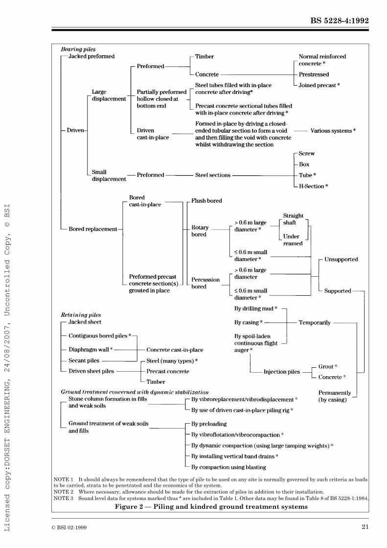
7.2 Types of piling
7.2.1 General
Piles can be divided into two main categories, bearing piles and retaining piles. It is possible in principle to install either category by driving, jacking or boring (see Figure 2). Ground or other site conditions can, however, prohibit the use of one or other of these techniques, that are described in more detail in 7.2.2 to 7.2.4.There are other methods of forming medium to deep foundations under certain conditions. These include the installation of stone columns by vibroreplacement (see 7.2.5), deep compaction by dynamic consolidation (see 7.2.6), and the technique of diaphragm walling (see 7.2.7). Although the mechanical plant and equipment can differ in some ways from those used in conventional piling, the problems of protecting the neighbourhood from noise disturbance are similar.
7.2.2 Driven piles
In conventional driven piling, a hammer is used to strike the top of the pile via a helmet and/or a sacrificial dolly. High peak noise levels will arise as a result of the impact. The hammer can be a simple drop hammer or it can be actuated by steam, air, hydraulic or diesel propulsion. Displacement piles can be top driven, bottom driven or can be driven by means of a mandrel.In certain ground conditions it may be possible to drive piles using a vibratory pile driver, in which cases high impact noise may not arise, but the continuous forced vibration together with structure-borne noise can give rise to some disturbance.When piles are driven for temporary works further disturbance can occur at a later date when the piles are extracted.
7.2.3 Jacked piles
A method for installing either retaining or bearing steel piles without either hammering or vibratory driving is by jacking. One or a pair of piles is pushed into the ground using the reaction of a group of several more adjacent piles. The main source of noise is the engine driving the hydraulic power pack for the jacking system. Other sources of noise include cranes and ancillary equipment. The use of jacked piles is appropriate in most types of cohesive soil and silty sands, but specialist advice should be sought in such cases.
7.2.4 Bored piles
Bored piles can be constructed by means of a rotary piling rig or by impact boring. In the former case the major source of noise is the more or less steady noise of the donkey engine that supplies the power to perform the drilling. In certain types of soil it is necessary to insert casings for part of the depth. If the casings have to be driven in and/or extracted by hammering, high peak noise levels will result. Similar considerations apply to the impact boring technique. The noise characteristics may therefore be at a relatively steady and continuous level with intermittent high peaks superimposed upon it.A method for boring piles that does not need a temporary casing is the use of a continuous flight auger and the injection of concrete or grout to form the piles. It is applicable only in certain ground conditions and the range of pile diameters is limited.
7.2.5 Vibroflotation/vibrocompaction and vibroreplacement/vibrodisplacement
A method for improving the bearing capacity of weak soils and fills is to use a large vibrating poker which can be mounted on a crane or an excavator base. In loose cohesionless soils the vibrations cause compaction to a denser state; this process is known as vibroflotation or vibrocompaction. In other weak soils a vibrating poker is used to form a hole which is then backfilled with graded stone and compacted by the poker; this process is known as vibroreplacement or vibrodisplacement. Water or compressed air can be used as a jetting and flushing medium.Typically, vibrating pokers are actuated by electric or hydraulic motors. To reduce the noise of the operation, attention should be paid to the generator or power pack as appropriate. Other sources of noise could include pumps when using water flush, or air escaping from the poker when this is exposed.
Licensed copy:DORSET ENGINEERING, 24/08/2007, Uncontrolled Copy, © BSI

BS 5228-4:1992
© BSI 02-1999 19
7.2.6 Deep compaction by dynamic consolidation
An alternative method for improving the bearing capacity of weak soils and fills is to drop a large tamping weight from a height on to the ground at selected locations. Typically in the UK, tamping weights between 10 t and 20 t are used and are dropped from heights between 10 m and 25 m, although in some cases other weights and drop heights can be used. The tamping weight is normally raised by and dropped from a very large crawler crane and the noise characteristic contains both steady (crane engine) and impulsive (impact of weight on ground) components.
7.2.7 Diaphragm walling
When deep foundation elements with both retaining and bearing capabilities are needed, the technique of diaphragm walling may be applicable. The soil is excavated in a trench under a mud suspension (e.g. bentonite) in a series of panels, usually using a special clamshell grab; when the full depth has been reached a reinforcing cage is inserted and concrete is placed by tremie pipe, thus displacing the mud to the surface.The grab is normally suspended from a crawler crane although a tracked excavator base may sometimes be used. It is operated either by gravity or hydraulically in which latter case it is guided by a kelly bar. Diaphragm walling sites frequently need much ancillary equipment including bentonite preparation and reclamation plant, reinforcing cage manufacturing plant, pumps and handling cranes. The layout of plant on the site is important for efficient operation and can exert considerable influence on noise control.
7.3 Noise reduction techniques
7.3.1 Piling operations
Noise can be reduced at source or, when this is not possible, the amount of noise reaching the neighbourhood can be reduced by various means.Impact noise when piling is being driven can be reduced by introducing a non-metallic dolly between the hammer and the driving helmet. This will prevent direct metal-to-metal contact, but will also modify the stress wave transmitted to the pile, possibly affecting the driving efficiency. The energy absorbed by the dolly will appear as heat. Further noise reduction can be achieved by enclosing the driving system in an acoustic shroud. Several commercially available systems employ a partial enclosure arrangement around the hammer. It is also possible to use pile driving equipment that encloses the hammer and the complete length of pile being driven, within an acoustic enclosure.
For steady continuous noise, such as that caused by diesel engines, it may be possible to reduce the noise emitted by fitting a more effective exhaust silencer system or by designing an acoustic canopy to replace the normal engine cover. Any such project should be carried out in consultation with the original equipment manufacturer and with a specialist in noise reduction techniques. Caution should be exercised in order that the replacement canopy does not cause the engine to overheat and does not interfere excessively with routine maintenance operations.It may be possible in certain circumstances to substitute electric motors for diesel engines, with consequent reduction in noise. On-site generators supplying electricity for electric motors should be suitably enclosed and appropriately located.Screening by barriers and hoardings is less effective than total enclosure but can be a useful adjunct to other noise control measures. For maximum benefit, screens should be close either to the source of noise (as with stationary plant) or to the listener. It may be necessary for safety reasons to place a hoarding around the site, in which case it should be designed taking into consideration its potential use as a noise screen. Removal of a direct line of sight between source and listener can be advantageous both physically and psychologically.Consideration should be given to the possible application of some of the alternative techniques of piling referred to in 7.2. For convenience these are grouped together in Figure 2.
7.3.2 Location and screening of stationary plant
In certain types of piling works there will be ancillary mechanical plant and equipment that may be stationary, in which case care should be taken in location, having due regard also for access routes. Stationary or quasi-stationary plant might include, for example, bentonite preparation equipment, grout or concrete mixing and batching machinery, lighting generators, compressors, welding sets and pumps. When appropriate, screens or enclosures should be provided for such equipment.
7.3.3 Mobile ancillary equipment
Contributions to the total site noise can also be anticipated from mobile ancillary equipment, such as handling cranes, dumpers, front end loaders, excavators, and concrete breakers. These machines may only have to work intermittently, and when safety permits, their engines should be switched off (or during short breaks from duty reduced to idling speed) when not in use.
Licensed copy:DORSET ENGINEERING, 24/08/2007, Uncontrolled Copy, © BSI

BS 5228-4:1992
20 © BSI 02-1999
7.3.4 Maintenance and off-site traffic
All mechanical equipment and plant should be well maintained throughout the duration of piling works.When a site is in a residential environment, lorries should not arrive at or depart from the site at a time inconvenient to residents.
Licensed copy:DORSET ENGINEERING, 24/08/2007, Uncontrolled Copy, © BSI
BS 5228-4:1992
© BSI 02-1999 21
NOTE 1 It should always be remembered that the type of pile to be used on any site is normally governed by such criteria as loads to be carried, strata to be penetrated and the economics of the system.NOTE 2 Where necessary, allowance should be made for the extraction of piles in addition to their installation.NOTE 3 Sound level data for systems marked thus * are included in Table 1. Other data may be found in Table 8 of BS 5228-1:1984.
Figure 2 — Piling and kindred ground treatment systems
Licensed copy:DORSET ENGINEERING, 24/08/2007, Uncontrolled Copy, © BSI

BS 5228-4:1992
22 © BSI 02-1999
Section 3. Vibration
8 Factors to be considered when setting vibration control targets8.1 General
The most common form of vibration associated with piling is the intermittent type derived from conventional driven piling. Each hammer blow transmits an impulse from the head to the toe of the pile and free vibrations are set up. Sensors at a remote receiving point would indicate a series of wave disturbances, each series corresponding to one blow. (See also Appendix A.)When setting targets for maximum vibration levels (8.2 to 8.6) reference should be made to the existing ambient vibration levels, which should be measured prior to commencement of pile driving. This is particularly applicable on sites adjacent to roads carrying heavy commercial traffic, railway tracks and large industrial machinery. It is not uncommon for vibrations from such sources to mask vibrations from pile driving.
8.2 Vibration levels
The intensity of each vibration disturbance registered at the remote receiving point will normally be a function of many variables including:
a) energy per blow or cycle;b) distance between source and receiver;c) ground conditions at the site, e.g. soft or hard driving and location of water table;d) soil-structure interaction, i.e., nature of connection between soil and structure being monitored;e) construction of structure and location of measuring points, e.g.:
1) soil surface;2) building foundation;3) internal structural element.
In soft driving conditions, where a significant proportion of the energy per blow is directly used in advancing the pile, the intensity of vibrations transmitted to the environment is generally less than under hard driving conditions, where so much of the energy per blow is devoted to overcoming resistance to penetration that relatively little is available to advance the pile.When driving piles in soft soils the free vibrations set up are found usually to have a greater low frequency content than when driving into denser soils or rocks.
Various empirical formulae have been proposed relating the intensity of vibration measured at the remote receiving point, to the distance between it and the source and the energy of the source. The use of such formulae enables a rough estimate to be made as a check on the acceptability of the proposed process from a vibration standpoint, prior to the commencement of the piling works. This estimate could also assist, with applications under Section 61 of the Control of Pollution Act 1974 for prior consent (see 4.4). For guidance regarding the prediction of expected vibration levels see Appendix B.NOTE 1 Appendix B is included for information only and does not form part of this standard.NOTE 2 See Appendix C for examples of vibration levels measured under various conditions throughout the UK.
8.3 Human response to vibration
Human beings are known to be very sensitive to vibration, the threshold of perception being typically in the peak particle velocity range of 0.15 mm/s to 0.3 mm/s, at frequencies between 8 Hz and 80 Hz. Vibrations above these values can disturb, startle, cause annoyance or interfere with work activities. At higher levels they can be described as unpleasant or even painful. In residential accommodation vibrations can promote anxiety lest some structural mishap might occur. Guidance on the effects on physical health of vibration at sustained high levels is given in BS 6841, although such levels are unlikely to be encountered as a result of piling operations.BS 6472 sets down vibration levels at which minimal adverse comment will be provoked from the occupants of the premises being subjected to vibration. It is not concerned primarily with short term health hazards or working efficiency. It points out that human response to vibration varies quantitatively according to the direction in which it is perceived. Thus, generally, vibrations in thefoot-to-head mode are more perceptible than those in the back-to-chest or side-to-side modes although at very low frequencies this tendency is reversed.Base curves in terms of both vibratory acceleration and peak particle velocity in the different coordinate directions are shown in BS 6472. These curves apply to continuous vibrations and there is a series of multiplying factors which can be applied according to the sensitivity of the location to vibrations. In addition, formulae are quoted which may be used to establish minimal adverse complaint levels where the vibrations are intermittent but overall of relatively short duration in comparison to the daytime or night-time period.A kindred problem is that vibrations may cause structure-borne noise which can be an additional irritant to occupants of buildings. Loose fittings are prone to rattle and movement.
Licensed copy:DORSET ENGINEERING, 24/08/2007, Uncontrolled Copy, © BSI

BS 5228-4:1992
© BSI 02-1999 23
8.4 Structural response to vibration
8.4.1 General
Structural failure of sound buildings or building elements or components is not a phenomenon generally attributed to vibration from well controlled piling operations. Extensive studies carried out in this country and overseas have shown that documented proof of actual damage to structures or their finishes resulting solely from piling vibrations is rare. There are many other mechanisms which cause damage especially in decorative finishes and it is often incorrectly concluded that piling vibrations should be blamed.In some circumstances, however, it is possible for the vibrations to be sufficiently intense to promote minor damage. Typically this damage could be described as cosmetic and would amount to the initiation or extension of cracks in plasterwork, etc., rather than the onset of structural distress. In more severe cases, falls of plaster or loose roof tiles or chimney pots may occur.NOTE 1 It has been suggested that vibrations generally provide one trigger mechanism which could result in the propagation of an incipient “failure” of some component which hitherto had been in a metastable state.NOTE 2 Vibration can increase the density of and cause settlement in loose, wet and cohesionless soils, which may put structures at risk.
The making of an assessment of the vulnerability or otherwise of building structures to vibration induced damage needs rather more detailed structural knowledge at the outset than is generally available. Among the points to bear in mind are the following:
a) the design of the structure;b) the nature, condition and adequacy of the foundations and the properties of the ground supporting these;c) the age of the structure;d) the method and quality of construction, including finishes;e) the general condition of the structure and its finishes;f) a schedule of existing defects, especially cracks, supplemented where necessary by a photographic record;g) any information pertaining to major alterations, such as extensions, or past repair work;h) the location and level of the structure relative to the piling works;
i) the natural frequencies of structural elements and components;j) the duration of piling operations.
8.4.2 Response limits of structures
It is recommended that, for soundly constructed residential property and similar structures which are in generally good repair, a conservative threshold for minor or cosmetic (i.e. non-structural) damage should be taken as a peak particle velocity (p.p.v.) of 10 mm/s for intermittent vibration and 5 mm/s for continuous vibrations. Below these vibration magnitudes, minor damage is unlikely to occur. Current experience suggests that these values may be reduced by up to 50 % where the preliminary survey reveals existing significant defects (such as a result of settlement) of a structural nature, the amount of the reduction being judged on the severity of such defects. The range of frequencies excited by piling operations in the soil conditions typical in the United Kingdom is between 10 Hz and 50 Hz. Acceptable values of p.p.v. may need adjustment for predominant frequencies outside this range.NOTE 1 At low frequencies (below 10 Hz), large displacements and associated large strains necessitate lower p.p.v. values (50 % lower), whereas at high frequencies (above 50 Hz), much smaller strains allow the p.p.v. limits to be increased (100 % higher).
Buildings constructed for industrial and commercial use exhibit greater resistance to damage from vibrations than normal dwellings, and it is recommended that light and flexible structures (typically comprising a relatively light structural frame with infill panels and sheet cladding) should be assigned thresholds of 20 mm/s for intermittent vibrations and 10 mm/s for continuous vibrations, whereas heavy and stiff buildings should have higher thresholds of 30 mm/s for intermittent vibrations and 15 mm/s for continuous vibrations.Where buildings appear not to conform precisely to one or other of the descriptions given in this subclause, the thresholds may be adjusted within those stated.NOTE 2 Additional guidance on the relative sensitivities of various types of building to vibrations is given in BS 7385-1.
Special consideration should be given to ancient ruins and listed buildings1).The vibration levels given in this subclause refer to the maximum value on a load bearing part of the structure at ground or foundation level in the vertical, radial or tangential direction. See Figure 3.
1) See also WATTS, G.R., Case Studies of the Effects of Traffic Induced Vibrations on Heritage Buildings. TRRL Research Report 156, 1988. Available from the Transport and Road Research Laboratory, Old Wokingham Road, Crowthorne, Berkshire RG11 6AU.
Licensed copy:DORSET ENGINEERING, 24/08/2007, Uncontrolled Copy, © BSI

BS 5228-4:1992
24 © BSI 02-1999
In certain circumstances it may be necessary in addition to specify limits at other locations. For example, modern multi-storey buildings employing continuous construction methods exhibit little inherent damping. Significant amplification of incoming vibrations can, therefore, occur at the upper storeys, notably in the horizontal modes. Likewise, amplification of vibrations (mostly vertical) can occur in the middle of suspended floors. A vertical p.p.v. of up to 20 mm/s during driven piling may be tolerated at such positions. However special care may be needed for old plaster and lath ceilings beneath suspended floors.NOTE 3 Amplification factors will vary according to individual circumstances, but factors of between 1.5 and 2.5 are typical.
8.5 Assessment of vulnerability of structures and services
8.5.1 Retaining walls
Unlike conventional buildings, which are tied together by crosswalls, intermediate floors and roofs, retaining walls may have little lateral restraint near their tops. This can result in substantial amplification of vibrations particularly in the horizontal mode normal to the plane of the wall. Amplification factors of between 3 and 5 are typical.
For slender and potentially sensitive masonry walls it is recommended that threshold limits for p.p.v. of 10 mm/s at the toe and 40 mm/s at the crest should generally be adopted. Propped or tied walls or mass gravity walls can be subject to values 50 % to 100 % greater than the above. Similar values could be applied to well supported steel pile and reinforced concrete retaining walls. Where walls are in poor condition the allowable values should be diminished and at the same time additional propping or other methods of support should be devised. For continuous vibrations all the above levels should be reduced by a factor of 1.5 to 2.5 according to individual circumstances.
8.5.2 Slopes and temporary excavations
When piling is to be installed close to slopes, vibration of any form may cause movement of the slope material.The effect of ground borne vibrations on the stability of’ temporary earthworks such as modified soil slopes and open excavations should receive careful consideration in order to avoid risk to personnel and partially completed works from dislodged lumps of soil, local collapse of soil faces or even ground movement due to overloading and failure of temporary ground retention systems.
Figure 3 — Orientation of vibration transducers
Licensed copy:DORSET ENGINEERING, 24/08/2007, Uncontrolled Copy, © BSI
BS 5228-4:1992
© BSI 02-1999 25
The risk to stability is dependent on the extent to which the factor of safety under static loading is reduced by the vibrations, and hence on the intensity, characteristics and duration of the vibration and the soil response. The possibility that inherent weaknesses might exist in the soil due to the release of stress and subsequent surface weathering should be borne in mind.When the pile type is chosen, care should be taken to avoid substituting the risk from vibration, pore pressure changes and soil displacement associated with driven piling and other systems which generate vibrations, by threats to stability resulting from uncontrolled soil removal or the release of ground water.Consideration should be given to the use of controlled trials to establish a safe method of working, from observations of vibration intensity, of the onset of local distress to the soil face and of changes in line and level.Where doubt about the loss of stability remains, action should be taken either to phase the work so that piling can be completed before earthworks are carried out, or to retain the soil effectively to allow piling to take place safely.
8.5.3 Underground services
Some statutory undertakings have introduced criteria governing the maximum level of vibrations to which their services should be subjected. These vibrations are usually extremely conservative and it is recommended that the following limits be used:
a) maximum p.p.v. for intermittent or transient vibrations 30 mm/s;b) maximum p.p.v. for continuous vibrations 15 mm/s.
Values should be applied at the crown unless the lateral dimension of the service is large in relation to the space between the service and the pile.It should be noted that even a p.p.v. of 30 mm/s gives rise to a dynamic stress which is equivalent to approximately 5 % only of the allowable working stress in typical concrete and even less in iron or steel.In the event of encountering elderly and dilapidated brickwork sewers the base data should be reduced by 20 % to 50 %. For most metal and reinforced concrete service pipes, however, the values in a) and b) should be quite tolerable. There is often some difficulty in assessing the true condition of underground pipes, culverts and sewers. Among the factors which could mean that such services are in a state of incipient failure are poorly formed joints, hard spots, badly prepared trench bases, distortion due to settlement or heave, or unstable surrounding ground caused by previous or existing leaks.
NOTE The extraction of temporary piling can also generate vibration.
8.6 Assessment of vulnerability of content of buildings
8.6.1 Computer installations
Although modern computer installations incorporate solid state electronics, the disc drive units are considered to be vulnerable to excessive vibration or shock. These devices generate their own continuous internal vibrations from the spinning discs and associated machinery. Major manufacturers have set acceptable external vibration criteria for their equipment, in both operating and transit modes.The criteria are often expressed in terms of limits on vibratory displacement up to a certain frequency and limits on vibratory acceleration at higher frequencies. A sinusoidal relationship is given between these parameters which can therefore be used to calculate the corresponding particle velocities. For continuous vibrations the allowable thresholds are set at about 40 % of the permitted levels of intermittent vibrations. An example from one major manufacturer quotes permitted levels for intermittent vibrations varying between 50 mm/s at 8 Hz and 10 mm/s at 40 Hz, a frequency range which covers much of that associated with piling in soils. These criteria are judged to apply to computer equipment correctly installed on the ground floor of a building.Thus computers are not as fragile as is often believed and, with care, piling need not pose a threat to the continued safe use of a typical computer installation. Extra care may be needed if the installation is mounted on a suspended floor which might accentuate the level of transmitted vibrations.
8.6.2 Telephone exchanges
In telephone exchanges where electro-mechanical methods of circuit selection are used, excessive vibrations of the appropriate frequencies may set up resonances in the contact arms leading to wrong lines or other malfunction. Research on one type of installation resulted in the adoption of a limiting p.p.v. of 5 mm/s for intermittent vibrations, as measured on the floor of the exchange room. With advances in telecommunication technology many different systems exist, some of which are less sensitive to vibration. Individual installations should be treated on their merits.
Licensed copy:DORSET ENGINEERING, 24/08/2007, Uncontrolled Copy, © BSI
BS 5228-4:1992
26 © BSI 02-1999
8.6.3 Miscellaneous
The sensitivity to vibrations of hospital operating theatres, especially those where microsurgery is undertaken, can well be imagined. Some scientific laboratories are similarly susceptible, whilst a range of other industrial processes ranging from optical typesetting to automatic letter sorting could be inconvenienced. In electrical power generation, turbine shafts are not able to accommodate large oscillatory displacements.Where there is uncertainty concerning the level of transmitted vibration and its acceptability to the particular environment, it is advisable to investigate the actual conditions and requirements in detail. Preliminary trials and monitoring can then be designed to establish a suitable procedure for the work.
9 Practical measures to reduce vibration9.1 General
Where the predictions indicate that a particular piling method could prove marginal in terms of critical vibration levels, further consideration should be given to the problem along the lines suggested in 8.4. Additionally, methods of alleviating the problem may be adopted as recommended in 9.2.
9.2 Reduction of transmitted vibration levels
9.2.1 Use of alternative methods
As with noise control methods it should be borne in mind that piling and ground engineering processes are primarily selected on the basis of the strata to be encountered, the loads to be supported and the economics of the system. After consideration of these constraints, however, it should be possible to select the process least likely to give rise to unacceptable vibrations in particular circumstances. Examples would include the use of continuous flight auger injected piles, jacked preformed piles, auger bored piles, or possibly impact bored piles in preference to driven piles. Some form of ground treatment might also be possible, depending on soil conditions and loading requirements.
There are sometimes cases in which the majority of a site is amenable to a particular form of ground treatment or foundation construction but where a limited area is too close to existing structures or services to permit unrestricted use of the process. For example, from Table 1 it may be deduced that dynamic compaction using large tamping weights should be kept a reasonable distance away from such features. If a small intervening area remains to be treated this may be done using one of the vibro processes of ground treatment. Similarly, the majority of a site may be piled using the driven cast-in-place process leaving a minority to be completed with continuous flight auger injected piling.It should be noted that a change in method part of the way across the site might result in a mismatch in subsequent foundation behaviour. The engineering implications of any such changes should be considered carefully prior to construction on site.
9.2.2 Removal of obstructions
Obstructions constitute a hindrance to progress and exacerbate the transmission of environmental vibrations, especially where they occur at shallow depths. Obstructions known to exist, e.g. old basement floors, old foundations, timbers, etc., should be broken out at pile or stone column positions and the excavation backfilled. Where an unexpected obstruction is encountered it may be preferable that piling should be halted at that position until such time as the obstruction can be dealt with, rather than attempting prolonged hard driving.
9.2.3 Provision of cut-off trenches
A cut-off trench may be regarded as analogous to a noise screen, in that it interrupts the direct transmission path of vibrations between source and receiver. It should be noted that there are serious limitations to the efficacy of trenches. For maximum effect the trench should be as close to the source or to the receiver as possible. The trench should have adequate length and adequate depth. With normally available excavators on site, trench depths are seldom in excess of 4 m or 5 m. The length of the trench needed would be a function of the relevant plan dimensions of the piling site and the structure to be protected.
Licensed copy:DORSET ENGINEERING, 24/08/2007, Uncontrolled Copy, © BSI

BS 5228-4:1992
© BSI 02-1999 27
A trench may constitute a safety hazard. If the trench is not self-supporting, a flexible support mechanism, e.g. bentonite suspension may be needed. Care should be exercised in locating the trench to avoid any loss of support to the structure it is intended to protect or to the piles being installed. Care should also be taken to ensure that the stability of the piling equipment is not endangered by the presence of the trench. The wall of the trench closest to the piling operation may suffer progressive collapse during the course of the works. Provided that the safeguards in this clause are observed, such behaviour is acceptable as an energy releasing mechanism.At the conclusion of the relevant piling operations the trench should be backfilled carefully to reinstate the site.Specialist advice should be sought prior to embarking on cut-off trench construction. Trenches should not be regarded as the universal panacea for vibration problems.
9.2.4 Reduction of energy input per blow (or cycle)
Consideration of the relationships 1) and 2) (see Appendix B) suggests that there is a dependence of the peak particle velocity on the energy input. For both relationships, the p.p.v. is seen to depend on the square root of the energy input. For example, halving the energy per blow (or cycle) would produce a p.p.v. of 71 % of its original value. It is sometimes found that reducing energy per blow has an appreciable effect at close quarters, but that at greater distances there is sufficient scatter in the results to indicate that modifications to the energy do not appear significantly to influence the p.p.v.The penalty for adopting this method is that more blows at lower energy will be needed to drive the piles to a required depth. The trade-off will not necessarily be linear owing to other losses in energy in the system. The advent of modern hydraulic hammers, in particular, has permitted a greater degree of control, and flexibility in selection, of input energy and this may be used to advantage, in combination with appropriate monitoring, to minimize problems. For example, when driving piles close to buildings with shallow foundations or in the vicinity of shallow buried services, monitoring of the vibrations could enable an assessment to be made as to the appropriateness of starting the drive with low hammer drops, subsequently increasing the energy as the toe of the pile reaches the founding stratum at greater depth.
Although in general terms it is accepted that vibrations at any level may contribute to fatigue mechanisms in structures, the relative importance of vibration intensity and number of cycles at that intensity is not sufficiently understood. Under the appropriate circumstances, however, it may be more acceptable, or even preferable, to reduce the energy per blow, thus limiting the p.p.v. but sustaining a longer period of pile driving.NOTE Special arrangements may be needed where piles are driven to a set. Driving to a set entails counting a number of blows from a standard height of drop (standard for the particular piling system) for a given (small) penetration, or by measuring the penetration obtained after a given number of blows from the standard height of drop. It should be borne in mind that set may not be achieved when using the lower drop height initially chosen to reduce vibration magnitude.
9.2.5 Reduction of resistance to penetration
9.2.5.1 Pre-boring for driven piles
When piles are to be driven and there is the risk of excessive vibrations emanating especially from the upper strata, the problem can sometimes be reduced by pre-boring. This process removes some of the soil which would otherwise have to be displaced in the early stages of pile driving. There is some evidence to suggest that the final level of vibration during driving would not be reduced, although there would be a reduction in the number of blows needed to achieve the proper penetration.A variant of this procedure which can be used with top driven cast in place piling is to commence by driving the tube open-ended. A plug of soil is formed within the tube, which is then withdrawn and the plug is removed. This may be repeated several times before the shoe is fitted and the tube driven closed-ended in the normal manner.
9.2.5.2 Mudding in for rotary bored piles
Whilst pre-boring is used in the construction of rotary bored piles in order to reduce the resistance of penetration of temporary casing, it is often coupled with mudding in to reduce the risk of collapse of the sides of the bore.Following normal pre-boring a small quantity of bentonite slurry is added to the borehole and the auger is rotated rapidly in order to stir up the slurry and any collapsed material from the unlined sides. The casing is then offered into the hole, its penetration being assisted by the lubricating action of the mud slurry. Depending on conditions the final seating of the casing may be assisted either by use of a twister bar (the casing being spun in), or by tapping with a heavy casing dolly or by using a vibrator. The use of these latter two items should, however, be minimized.
Licensed copy:DORSET ENGINEERING, 24/08/2007, Uncontrolled Copy, © BSI

BS 5228-4:1992
28 © BSI 02-1999
9.2.5.3 Adding water to the bore hole for impact bored piles
The level of vibration from the impact bored piling method is generally considered acceptable and the method is frequently used on confined sites adjacent to existing structures. The level of vibration increases with the resistance to boring and particularly when the boring tool fails to make measurable progress, for example in dense dry gravel. Progress can be increased by adding water to the bore but great care is needed to ensure that the casing is advanced in pace with the boring tool and that excessive use of water is avoided to reduce overboring and the consequent risk of undermining adjacent structures.
9.2.6 Excavation under bentonite
An alternative procedure for bored piles using very long casings where there are substantial depths of water bearing sands and silts, is to drill the piles under bentonite suspension.It may then be possible to restrict casing to a relatively short length, thereby avoiding the need to resort to the use of either vibratory or percussive dollies for insertion or withdrawal.
9.2.7 Avoidance of shear leg contact with sensitive structures
Tripod impact bored piling rigs can impart vibrations and shocks through the shear legs. Where, as is often the case, there is a confined working area for a tripod care should be taken in setting up the rig at any pile position, to avoid having one of the legs or its support in direct contact with any adjacent building which may be sensitive to vibrations.
9.2.8 Removal of the “plug” when using casing vibrators
As explained in A.3, vibratory drivers have difficulty in penetrating dense cohesionless soils. Where such a machine is used to insert a casing into a stratum of medium dense to dense granular soil, a plug of this soil will accumulate inside the casing. The vibrator will now be confronted with additional resistance, thus slowing penetration and probably accentuating environmental vibration levels.Provided the boring rig has a sufficiently high rotary table it should be used to drill out the plug at intervals between short periods of vibratory driving. This procedure should substantially reduce the total amount of time needed for use of the vibrator.
9.2.9 Bottom-driving
Claims are made from time to time that bottom-driving results in lower vibration levels than top-driving. The method can be applied to some permanently cased piles and some specialized cast-in-place systems.The process is certainly quieter than its top-driven counterpart; however any reduction in vibration intensity may be associated with the generally slower rate of production. Maintaining the same rate of pile penetration as top-driving may result in similar vibration levels.
10 Measurement10.1 Monitoring
In order to ensure optimum control of vibration, monitoring should be regarded as an essential operation. In addition to vibration monitoring, static tell-tale measurements can also be useful. Precision tell-tales are capable of registering longer term trends and can provide early warning of impending structural problems.It should be remembered that failures, sometimes catastrophic, can occur as a result of conditions not directly connected with the transmission of vibrations, e.g. the removal of supports from retaining structures to facilitate site access.Where site activities other than pile driving may affect existing structures, a thorough engineering appraisal of the situation should be made at the planning stage.
10.2 Methods of measurement
10.2.1 General
The method selected to characterize building vibration will depend upon the purpose of the measurement and the way in which the results are intended to be used. Although a measurement technique which records unfiltered time histories allows any desired value to be extracted at a later stage, it may not be strictly necessary for the purpose of routine monitoring.
10.2.2 Positions
The number of measurement positions will also depend upon the size and complexity of the building.
Licensed copy:DORSET ENGINEERING, 24/08/2007, Uncontrolled Copy, © BSI

BS 5228-4:1992
© BSI 02-1999 29
When the purpose is to assess the possibility of structural damage, the preferred primary position is in the lowest storey of the building, either on the foundation of the outer wall, in the outer wall, or in recesses in the outer wall. For buildings having no basement, the point of measurement should be not more than 0.5 m above ground level. For buildings with more than one storey, the vibration may be amplified within the building. In the case of horizontal vibration, such amplification may be in proportion to the height of the building, whereas vertical vibration tends to increase away from walls, towards the mid-point of suspended floors.It may therefore be necessary to carry out measurements (which should be simultaneous if a transfer function is required) at several other positions to record maximum vibration magnitudes. When the building is higher than four floors (approximately 12 m) additional measuring points should be added every four floors and at the top of the building. When the building is more than 10 m long, the measuring positions should be selected at a horizontal spacing not exceeding 10 m. Measurements should be made on the side of the building facing the source.When the purpose is to evaluate human exposure to vibration in the building, or to assess the effect of vibration on sensitive equipment within the building, measurements should be taken on the structural surface supporting the human body or the sensitive equipment.When ground vibration sources are being considered it is usual to orientate the transducers with respect to the radial direction, defined as the line joining the source to the transducer.When studying structural response to ground vibration it is more usual to orientate transducers with respect to the major and minor axes of the building structure.If it is not possible to make measurements at the foundation, transducers should be well coupled to the ground.NOTE Information is given in BS 7385-1.
10.2.3 Parameter to measure
With an impulsive source of vibration it is usual to measure the peak value attained from the beginning to the end of a drive. It is also usual to measure in terms of peak particle velocity (p.p.v.) if the risk of damage to the building is the primary concern, and there is also an interest in human reaction. If the concern is purely for human tolerance, then acceleration is the preferred parameter. In the case of sensitive equipment, it is necessary to check the environmental vibration limit data supplied by the manufacturer and select accordingly.
Table 2 contains data that assist the selection of instrumentation.In order to adopt an appropriate cost effective piling procedure, a survey of the sensitivity of the neighbourhood to vibration prior to issuing tender documents is desirable.
10.2.4 Record sheets
An important aspect of monitoring vibrations is the preparation and maintenance of records of salient details of the site observations. The format to be adopted will vary according to the circumstances appropriate to each investigation.NOTE Appendix D contains examples of pro forma record sheets for site measurements and for vibration data summaries which have been devised for a multi-channel digital data acquisition system. Appendix D is included for information only and does not form part of this standard.
10.3 Trial measurements
The various formulae which have been developed empirically to predict vibration levels at a receiving point do not take into account variability of ground strata, the pile-soil interaction process, coupling between the ground and the foundations, etc. Hence these formulae can only provide a first assessment of whether or not the vibrations emanating from a site are likely to constitute a problem.More accurate assessment can be achieved by the “calibration” of the site, i.e. the establishment of a site-specific formula. The data necessary for the derivation of the formula can be obtained from a trial drive using a piling rig, or by dropping a large weight (typically 1 t to 2 t) in the case of impact driving, on to the ground surface and recording the vibration levels successively at various distances from the point of impact. The preferred method is to cast a 1 m cube of concrete and to drop it from a height of 1.5 m. A range of heights can however be employed, varying between 0.5 m and 2 m. The point of impact should be well away from adjacent structures.Vibration measurements may also be taken on structures to provide information on the coupling between the soil and the foundations and amplification effects within a building. A range of impact energies should be used to encompass the energy levels associated with the intended piling works.
Licensed copy:DORSET ENGINEERING, 24/08/2007, Uncontrolled Copy, © BSI

BS 5228-4:1992
30 © BSI 02-1999
Table 2 — Vibration effects on different subjects: the parameters to measure and the ranges of sensitivity of apparatus to use
Subject area Examples Measurement parameter and ranges of sensitivity
Equipment and processes Laboratory facilities Displacement between 0.25 mm and 1 mm in frequency range 0.1 Hz to 30 HzAcceleration between 10–4 g and 5 × 10⁻³ g in frequency range 30 Hz to 200 Hz
Microelectronics facilities p.p.v. between 6 mm/s and 400 mm/s in frequency range 3 Hz to 100 HzAcceleration between 0.5 × 10⁻³ g and 8 × 10⁻³ g in frequency range 5 Hz to 200 Hz
Precision machine tools Displacement between 0.1 mm and 1 mmComputer Displacement between 35 mm and 250 mm
Acceleration (r.m.s.) between 0.1 g and 0.25 g at frequencies up to 300 Hz
Microprocessors Acceleration between 0.1 g and 1 gPeople In dwellings or hospitals Vertical acceleration (r.m.s.) from 5 × 10⁻⁴ g
to 5 × 10⁻² g in frequency range 4 Hz to 8 Hz Vertical p.p.v. from 0.15 mm/s to 15 mm/s in frequency range 8 Hz to 80 HzHorizontal p.p.v. from 0.4 mm/s to 40 mm/s in frequency range 2 Hz to 80 Hz
In offices Vertical acceleration (r.m.s.) from 1 × 10⁻³ g to 1 × 10⁻¹ g in frequency range 4 Hz to 8 Hz Vertical p.p.v. from 0.5 mm/s to 20 mm/s in frequency range 8 Hz to 80 HzHorizontal p.p.v. from 1 mm/s to 52 mm/s in frequency range 2 Hz to 80 Hz
In workshops Vertical acceleration (r.m.s.) from 4 × 10⁻³ g to 6.5 × 10⁻¹ g in frequency range 4 Hz to 8 Hz Vertical p.p.v. from 1 mm/s to 20 mm/s in frequency range 8 Hz to 80 HzHorizontal p.p.v. from 3.2 mm/s to 52 mm/s in frequency range 2 Hz to 80 Hz
Buildings Residential or commercial
p.p.v. from 1 mm/s to 50 mm/s
Underground services Gas or water mains Displacement from 10 mm to 400 mm p.p.v. from 1 mm/s to 50 mm/s
NOTE 1 Except where root mean square (r.m.s.) accelerations are quoted, all measurement ranges, whether displacement, velocity or accelerations, are in terms of zero-to-peak.NOTE 2 The ranges given depend on the dominant frequency of vibration (see clause 8).NOTE 3 Typical ranges from equipment and processes vary considerably, depending on the sensitivity of the equipment installed.NOTE 4 gn is acceleration due to gravity, i.e. 9.81 m/s2.
Licensed copy:DORSET ENGINEERING, 24/08/2007, Uncontrolled Copy, © BSI

BS 5228-4:1992
© BSI 02-1999 31
Appendix A Description of vibrationA.1 Types of vibrationVibrations may be categorized in several ways as follows:
a) continuous vibrations in which the cyclic variation in amplitude is repeated many times;b) transient vibrations in which the cyclic variation in amplitude reaches a peak and then decays away towards zero relatively quickly;c) intermittent vibrations in which a sequence (sometimes regular, sometimes irregular) of transient vibrations occurs but with sufficient intervals between successive events to permit the amplitude to diminish to an insignificant level in the interim periods.
Examples of these types of vibration within the piling field are:1) continuous vibrations from a vibrating pile driver;2) transient vibrations from an isolated hammer blow;3) intermittent vibrations from a drop hammer pile driver.
NOTE Some air operated hammers have sufficiently rapid striking rates to prevent the amplitude of vibration diminishing to an insignificant level between successive events (or impacts). In spite of the impulsive nature of the wave form the resulting vibrations may be described as continuous.The response of soil and structures to continuous vibrations is to vibrate in sympathy with the vibrating source, i.e. at the same frequency or harmonics thereof. The resulting vibrations are, therefore, known as forced vibrations. Impulsive shocks giving rise to transient vibrations, on the other hand, excite the natural frequencies of the soil-structure combination and thus the resulting vibrations are known as free vibrations.A.2 Characteristics of vibrationVibrations are physically characterized as wave phenomena. They may be transmitted in one or more wave types, the most common of which are compression, shear and Rayleigh (or surface) waves. Each type of wave travels at a velocity which is characteristic of the material properties of the medium through which it is propagated. The wave velocity determines the time lag between the event at the source, e.g. the pile position and the remote receiving point. It does not, however, determine the severity of the vibration response at the remote receiving point, although the material properties of the transmitting medium play a significant role in this.As the wave passes through the receiving point the particles of matter undergo a vibratory or oscillatory motion. It is the intensity of these oscillatory particle motions which determine the vibration response at the receiving point.The oscillatory motion can be characterized physically in terms of the following:
a) a displacement about the mean value A;b) a particle velocity v;c) an acceleration a;d) frequency of the disturbance ƒ.
In the case of sinusoidal wave propagation these parameters are simply related by the formulae:v = 2πƒA
a = 4π2ƒ2A = 2πƒvwhere the symbols are each assigned their peak values.It is not normally practicable to measure all four parameters simultaneously and indeed this is not generally necessary, since for the majority of frequencies of interest in piling operations the peak particle velocity (p.p.v.) is the best indicator of the vibratory response, especially when it is combined with the frequency content of the disturbance. Further guidance on human response to vibrations may be found in BS 6472.
Licensed copy:DORSET ENGINEERING, 24/08/2007, Uncontrolled Copy, © BSI

BS 5228-4:1992
32 © BSI 02-1999
A.3 Vibrations associated with specific operationsA.3.1 Intermittent and transient vibrationsA.3.1.1 Single-acting pile hammersIntermittent vibrations are obtained with most single-acting pile hammers. A variety of mechanisms may be used to raise the hammer after each blow, e.g. winch rope, diesel, hydraulic, steam or compressed air. Some diesel and air hammers are double acting and have considerably more rapid striking (or repetition) rates than conventional free fall hammers. This may result in vibrations being set up in certain circumstances (see note to A.1).A.3.1.2 Impact bored pilingTraditional impact bored piling gives rise to intermittent vibrations, both in the boring process when the boring tool is allowed to fall freely to form the borehole, and also when temporary casing is being driven or extracted.A.3.1.3 Rotary bored pilingAlthough rotary bored piling tends to set up low level vibrations, transient vibrations may also occur when the auger strikes the base of the borehole. If it is necessary to insert an appreciable length of temporary casing to support the boring, a casing dolly may be used and, as with the impact bored piling method, this will give rise to intermittent vibrations. The use of special tools, such as chisels, will also result in intermittent vibrations.A.3.1.4 Clamshell grabsThe construction of diaphragm walls and barrettes using clamshell grabs may also give rise to transient or intermittent vibrations. The grabs may be operated either hydraulically, or by rope, but in each case they impact (with open jaws) on the soil in the trench. Since the excavation is filled with a bentonite suspension for temporary support there will be a modest buoyancy factor.A.3.1.5 Free falling tamping weightsGround treatment by dynamic compaction using large free falling tamping weights results in intermittent vibrations. The process is generally carried out on large sites to improve the density of relatively loose soils or fill materials. The major frequency content of the free vibrations tends to be very low.A.3.1.6 Other operations causing intermittent vibrationsThe formation of stone columns using plant designed for driven cast-in-place piling is another source of intermittent vibrations.A.3.2 Continuous vibrationsA.3.2.1 GeneralContinuous vibrations differ from intermittent or transient vibrations in that the vibratory stimulus is maintained through a sequence of cycles. If the frequency of the vibrations coincides with a natural frequency of, e.g. a structural element, then resonance can be induced. The resulting vibrations then exhibit substantially higher amplitudes than otherwise would be the case. This should be borne in mind if the criteria recommended in 8.4.2 are used for the setting of acceptable limits for vibrations at the remote receiving point.NOTE For continuous vibrations the variables mentioned primarily in conjunction with intermittent vibrations are all significant (except that energy per blow is replaced by energy per cycle) in determining the intensity of vibration.
Continuous vibrations are associated primarily with vibratory pile drivers. They are used for installing or extracting steel sheet and H-section piles and temporary or permanent casings for bored piles. Small vibrators are used for inserting reinforcement cages in continuous flight auger injected piles, and during the extraction of the driving tube following the concreting of a driven cast-in-place pile. The vibration in this latter case assists in compacting the concrete in the pile shaft, and the technique is employed as an alternative to hammering the tube during its extraction.A.3.2.2 Vibratory pile driversVibratory pile drivers can be very effective in loose to medium, cohesionless or weakly cohesive soils. The continuous vibration of the pile member effectively fluidizes the immediately surrounding soil, removing contact friction during a fraction of each vibration cycle. The mechanism is thwarted in dense cohesionless soils and stiff cohesive soils, and a vibrator used at length under these circumstances merely succeeds, in increasing the level of environmental vibrations at the expense of very slow penetration, especially with displacement piles.
Licensed copy:DORSET ENGINEERING, 24/08/2007, Uncontrolled Copy, © BSI

BS 5228-4:1992
© BSI 02-1999 33
Most vibratory pile drivers derive their cyclic axial motion from one or more pairs of horizontally opposed contra-rotating eccentric weights which may be powered hydraulically or electrically. The design operating frequency of these vibrators is typically in the range 25 Hz to 30 Hz which is rather higher than natural frequencies associated with loose or medium loose soil sites. This can lead to a high and possibly dangerous (although short-lived) response at the remote receiving station whenever the vibrator is switched on or off, as it accelerates or decelerates through the range either of site frequencies or of the natural frequencies of floor slabs, etc.NOTE 1 As a guide, whole building response for buildings up to four storeys in height, as opposed to building element response, generally occurs at frequencies between 5 Hz and 15 Hz. Buildings element response, e.g. slabs, may occur at frequencies between 5 Hz and 40 Hz. For buildings more than four storeys in height, the whole building response frequency is likely to be less than 5 Hz to 12 Hz.NOTE 2 Care should be taken when using vibrators with frequencies less than 25 Hz.
A.3.2.3 Resonant pile driversA similar principle to that for vibratory pile drivers applies to very high frequency resonant pile drivers. In this case the vibrator is capable of oscillating at high frequencies (up to 135 Hz) and is designed to tune to one of the natural modes of vibration of the pile being driven, in order to obtain the benefits of pile resonance.A.3.2.4 Continuous flight auger injected piling and jacked pilingThe levels of vibration associated with continuous flight auger injected piling and jacked piling are minimal as the processes do not involve rapid acceleration or deceleration of tools in contact with the ground but rely to a large extent on steady motions. Continuous vibrations at a low level could be expected from the prime movers.A.3.2.5 Vibroflotation and vibroreplacementIn ground treatment processes by vibroflotation or vibroreplacement, a rotating eccentric weight in the nose of the machine sets up a mainly horizontal vibration pattern. This is basically a much enlarged version of the familiar vibrating poker used for compacting concrete. Pokers for vibroflotation are generally energized by electric or hydraulic motors and typically operate at frequencies between 30 Hz and 50 Hz.A.3.2.6 Vibrating lancesAnother ground treatment process is the installation of vertical band drains. This may be achieved by using a vibrating lance. The vibrator is similar in concept to, but somewhat smaller than, vibrators used for pile driving.A.3.2.7 Other operations causing continuous vibrationsContinuous vibrations, albeit at low intensities, may be experienced from diesel engines, for example from impact bored piling winches mounted on skids, crawler mounted base machines, and attendant plant.
Appendix B Prediction of vibration levelsSimple empirical formulae relating peak particle velocity with source energy and distance from the pile were deduced by Attewell and Farmer2) from field measurements, and have been used for many years for prediction. More recent studies by Attewell and his co-workers have confirmed and refined their 1973 proposals, with a series of formulae characterizing different types of pile and piling hammer being derived. For the purpose of this appendix it is sufficient to note that a general relationship for hammer-driven piles is:
and for vibratory-driven piles is:
where:v is the peak particle velocity (vertical component) (in mm/s);
2) ATTEWELL, P.B., FARMER, I.W., Attenuation of ground vibrations from pile driving, Ground Engineering, 6(4), 26-29, 1973.
(1)
(2)
v 0.75 W o
r---------×=
v 1.0 W o
r---------×=
Licensed copy:DORSET ENGINEERING, 24/08/2007, Uncontrolled Copy, © BSI

BS 5228-4:1992
34 © BSI 02-1999
Wo is the source energy per blow (or per cycle) (in J);
r is the radial distance between source and receiver (in m).Use of either of these formulae will enable a prediction to be made of peak particle velocities (p.p.v.) which are unlikely to be exceeded significantly in the vast majority of cases. In fact in many cases the predicted values thus deduced will be found to over-estimate those which will occur in practice, for some or all of the following reasons.
a) Regression analysis of data from numerous case histories was performed on the highest peak particle velocities found in each data set rather than “average” values.b) Although in driven piling the source of the vibrations is axially directed and therefore predominantly vertical, the three-dimensional nature of the resulting wave pattern ensures that some oscillatory movement will occur in the horizontal plane. Furthermore, horizontal components may well dominate at elevated locations on retained or retaining walls or on structures subject to vibrations from vibroflotation operations.c) The constant 0.75 in equation (1) reconciles differences in units and averages soil conditions and driving efficiencies. Further commentary on the variations in vibration response depending on the nature of the soil may be found in other publications, e.g. Wiss (1967)3) and Martin (1980)4).d) Where the plan distance between the source and the receiver exceeds the depth of the pile it may reasonably be substituted for the radial distance r. However, when piling close to a structure the r value would be very dependent on pile depth, and so an indication of the depth at which significant resistance to driving is likely to occur would be important in making an assessment. In Table 3, r is generally taken as plan (or horizontal radial) rather than radial distance.e) Measurements made on the ground surface tend to yield levels which are greater than those made on adjacent load bearing structure. A variation of a factor of 2 is not uncommon (see for example Martin4) and Greenwood and Kirsch5)).f) It can be seen from Table 3 to Table 13 that in many cases satisfactory levels can be achieved when the remote receiving point (see 8.1) is at relatively close quarters. In this nearfield situation it is not practicable to discriminate between the various wave types.
Appendix C Measured vibration levelsInformation on measured vibration levels arising from various forms of piling and kindred operations has been summarized in Table 3 to Table 13. Data have been compiled from case histories recorded throughout the UK. Examination of the tabulated results will indicate the magnitude of scatter that can be anticipated.
3) WISS, J.F., Damage effects of pile driving vibrations, Highways Research Board USA No. 155, 14-20, 1967.4) MARTIN, D.J., Ground vibrations from impact pile driving during road construction, TRRL Supplementary Report 549, 1980, Transport and Road Research Laboratory, Crowthorne, Berkshire.5) GREENWOOD, D.A., and KIRSCH, K., Specialist ground treatment by vibratory and dynamic methods. Proceedings of the 1983 Institution of Civil Engineers International Conference on advances in piling and ground treatment forfoundations, 17-45. London, Thomas Telford, 1984.
Notes to Table 3 to Table 13N/R Not recorded or not reportedV VerticalH Horizontalp.p.v. Where peak particle velocities are quoted the values will normally be resultant or
substitute resultant values (i.e. vectorial sums of the three orthogonal components) unless indicated to the contrary.
* Indicates that the p.p.v. shown has been calculated from measured displacement and frequency of vibration.
+ Indicates that the p.p.v. shown has been calculated from measured acceleration and frequency of vibration.
♦§ Indicates that some annoyance (human perception of vibration) was reported.
91 See explanation in appropriate “Remarks” entry.
Licensed copy:DORSET ENGINEERING, 24/08/2007, Uncontrolled Copy, © BSI

BS 5228-4:1992
© BSI 02-1999 35
Ref No. Where the reference is unprefixed, this represents a case history associated with an actual site. Where investigations yielded inadequate (or no) measurements, they have been omitted.Where the reference number is prefixed by “C”, this represents a case history contributed to the CIRIA project RP299. The project report is CIRIA Technical Note 142 by J.M. Head and F.M. Jardine. Only case histories reporting measured vibration levels with relevant distances and some geographical information are included in the table. Where the reference number is prefixed by “M”, this represents a case history which does not fall into either of the above two categories.
P Penetration phase for vibroflotation/vibroreplacementC Compaction of stone column phase
Licensed copy:DORSET ENGINEERING, 24/08/2007, Uncontrolled Copy, © BSI

BS
5228-4:1992
36©
BS
I 02-1999
Table 3 — Summary of case history data on vibration levels measured during impact bored piling (tripod)
Ref. No.
Year and location
Soil conditions Pile dimensions
Mode Measured peak particle velocity (p.p.v.) at various plan distances Remarks
Theoretical energy per
blow
Plan distance
p.p.v. Plan distance
p.p.v. Plan distance
p.p.v.
m mm/s m mm/s m mm/s
1 1971 London EC2 Madeground/gravel/London clay
Depth 12 m Boring N/R 0.9 3.9* 2.4 1.6* 3.7 1.1* Measured on ground next to 17th century church
2 1972 London SW1 Made ground/softclay/ballast/London clay
500 mm f depth N/R 600 mm f depth N/R
Driving casing Base ramming gravel
N/R 21.5
3.3* 6.2*
63
1.8* 1.9*
6 0.5* Horizontal radial measurements
3 1973 London EC2 Madeground/peat/gravel/Londonclay
500 mm f 20 m depth
Driving casing N/R 2.5 2.8 Measured on 17th century church
4 ♦ 1974 Dundalk (Louth)
Soft silts/gravels/boulders
N/R Driving casing N/R 1.5 2.4 Cracking of adjacent property owing to loss of ground prior to piling
5 ♦ 1980 Luton (Beds) Ballast/chalk 600 mm f 8.5 m depth
Initial boring N/R 10 0.7 Shored retaining wall in poor condition
6 1980 York (N. Yorks)
Rubble with obstructions/soft silty clay/stiff clay
450 mm f 10.5 m depth
Boring Driving casingDriving casing against obstruction
N/RN/RN/R
11.21.2
84
16
2.5 4 8 2 Adjacent structures elderly with existing cracks
7 ♦ 1981Berwick-upon-Tweed (Northumberland)
Tarmac/soft sandySilty clay/sandstone bedrock
450 mm f
4 m to 8 m depth
Boring through tarmac Boring obstruction (boulder)
N/R
N/R
6
6
6.5
4.25
20 0.7 Vertical 4 mm/s at 6 m.Vertical component only measured
8 1982Stockton-on-Tees (Cleveland)
Fill including timbers/sand/boulder clay
450 mm f13 m to 18 m depth
Driving casing Boring through obstruction
N/R N/R
2.5 4
88
3.56.5
4 4
811
2 2
Old buildings (one listed) adjacent to site
9 1982 London SW1 Fill/sandysilt/wetballast/Londonclay below 9 m
600 mm f12 m depth
Boring N/R 1.5 2.2 Near to a telephone exchangeTrial borings (pre-contract)
Licensed copy:DORSET ENGINEERING, 24/08/2007, Uncontrolled Copy, © BSI
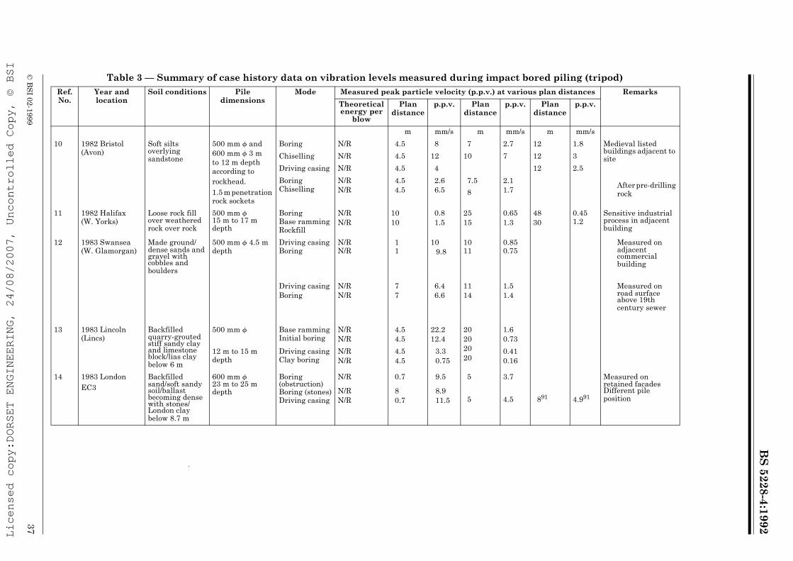
BS
5228-4:1992
© B
SI 02-1999
37
Table 3 — Summary of case history data on vibration levels measured during impact bored piling (tripod)Ref. No.
Year and location
Soil conditions Pile dimensions
Mode Measured peak particle velocity (p.p.v.) at various plan distances Remarks
Theoretical energy per
blow
Plan distance
p.p.v. Plan distance
p.p.v. Plan distance
p.p.v.
m mm/s m mm/s m mm/s
10 1982 Bristol (Avon)
Soft silts overlying sandstone
500 mm f and 600 mm f 3 m to 12 m depth according to rockhead.1.5 m penetration rock sockets
Boring N/R 4.5 8 7 2.7 12 1.8 Medieval listed buildings adjacent to siteChiselling N/R 4.5 12 10 7 12 3
Driving casing N/R 4.5 4 12 2.5
Boring Chiselling
N/RN/R
4.54.5
2.66.5
7.5
8
2.11.7
After pre-drilling rock
11 1982 Halifax (W. Yorks)
Loose rock fill over weathered rock over rock
500 mm f 15 m to 17 m depth
Boring Base ramming Rockfill
N/RN/R
1010
0.81.5
2515
0.651.3
4830
0.451.2
Sensitive industrial process in adjacent building
12 1983 Swansea (W. Glamorgan)
Made ground/dense sands and gravel with cobbles and boulders
500 mm f 4.5 m depth
Driving casing Boring
N/RN/R
11
109.8
1011
0.850.75
Measured on adjacent commercial building
Driving casingBoring
N/RN/R
77
6.46.6
1114
1.51.4
Measured on road surface above 19th century sewer
13 1983 Lincoln (Lincs)
Backfilled quarry-grouted stiff sandy clay and limestone block/lias clay below 6 m
500 mm f Base ramming Initial boring
N/RN/R
4.54.5
22.212.4
20202020
1.60.73
12 m to 15 m depth
Driving casing Clay boring
N/RN/R
4.54.5
3.30.75
0.410.16
14 1983 London EC3
Backfilled sand/soft sandy soil/ballast becoming dense with stones/London clay below 8.7 m
600 mm f 23 m to 25 m depth
Boring (obstruction) Boring (stones)Driving casing
N/R
N/RN/R
0.7
80.7
9.5
8.911.5
5
5
3.7
4.5 891 4.991
Measured on retained facades Different pile position
Licensed copy:DORSET ENGINEERING, 24/08/2007, Uncontrolled Copy, © BSI

BS
5228-4:1992
38©
BS
I 02-1999
Table 3 — Summary of case history data on vibration levels measured during impact bored piling (tripod)
Ref. No.
Year and location
Soil conditions Pile dimensions
Mode Measured peak particle velocity (p.p.v.) at various plan distances Remarks
Theoretical energy per
blow
Plan distance
p.p.v. Plan distance
p.p.v. Plan distance
p.p.v.
m mm/s m mm/s m mm/s
15 1984 Guildford (Surrey)
Surface crust/very soft clay/sands and gravels/clay clay horizon between 5 m and 8.5 m
450 mm f 12.5 m depth
Initial boring through crust
Driving casing Boring soft clay
N/R
N/RN/R
2.5
2.53.5
10.4
5.51.1
3.5
3.57
12.3
5.30.8
7
7
6.5
3.6
Sensitive equipment in adjacent building (protected by cut-off trench)
16 1984 London EC2 Madeground/dense ballast/London clay below 5.5m
600 mm f22 m depth
Driving casing Boring casingShaking clay out of pump Boring brick work obstruction
N/RN/R
N/R
N/R
33
3
6
7.14.1
7.5
8.6
5.55.5
5.5
9
2.31.6
0.75
2.6
10§10§
10§
13§
0.9§0.86§
0.45§
1.5§
Measured on retained facade
17 ♦ 1985 London EC3 Madeground/dense ballast/London clay below 6.5 m
500 mm f 8 m depth
Driving casing2 rigs (2nd at 10 m) N/R 4 2.5
Trial borings Computer equipment beyond party wall
Licensed copy:DORSET ENGINEERING, 24/08/2007, Uncontrolled Copy, © BSI

BS
5228-4:1992
© B
SI 02-1999
39
Table 4 — Summary of case history data on vibration levels measured during driven cast-in-place piling (drop hammer)Ref. No.
Year and location
Soil conditions Pile dimensions
Mode Measured peak particle velocity (p.p.v.) at various plan distances Remarks
Theoretical energy per
blow
Plan distance
p.p.v. Plan distance
p.p.v. Plan distance
p.p.v.
m mm/s m mm/s m mm/s
18 ♦ 1981 London SE1 Madeground/peat/Thames ballast/London clay below 10 m
500 mm f 6 m depth with enlarged base
Driving tube Enlarging base
N/R 2020
2.73.6
100100
0.961.4
Bottom-driven
19 ♦ 1982 London SW6
Fill/ballast/London clay
500 mm f 4 m to 7 m depth with enlarged base
Driving tube Expelling plug Enlarging base
N/RN/RN/R
303030
2.32.62.3
Bottom-driven
20 ♦ 1983 Aylesbury (Bucks)
Fill/soft material/clay becoming stiff
450 mm f 10 m depth with enlarged base
Driving tube Expelling plug Enlarging base
N/RN/RN/R
444
8.46.14.0
202020
5.04.84.4
Bottom-driven
21 ♦ 1983 Aldershot (Hants)
Dense fine sand 450 mm f approx 6 m depth
Driving tube 58.9 kJ 120 1.0 Tube driven open ended initially to remove some sand prior to driving with shoe top-driven
22 ♦ 1983 Horsham (W. Sussex)
Peaty, silty alluvia over shale and sandstone
350 mm f 7.5 m to 8 m depth
Driving tube Extracting tube
38.8 kJ 2121
2.93.2
2828
2.73.9
3535
2.43.1
Top-driven
23 ♦ 1983 Redhill (Surrey)
Dense fine sand with ironstone bands
450 mm f 8 m depth (max) (6 m average)
Driving tube Expelling plug
N/R 22.5 3.1 4343
1.11.25
Bottom-driven, computer etc. in adjacent building
24 ♦ 1984 Weymouth (Dorset)
2 m to 3 m thick crust of sands and gravel over astuarial silty clay becoming firmer at greater depth
350 mm f 15 m depthSome with enlarged base
Driving tube open endedDriving tube with shoeExtracting tubeEnlarging base
47.1 kJ
47.1 kJ
8.5
8.5
8.525
6.1
8.3
2.92.2
13
13
25
3.6
4.4
2.1
Top-driven
25 ♦ 1984 Cambridge (Cambs.)
4.75 m to 6.75 m loose fill over gault clay becoming stiffer with depth
350 mm f 10 m to 11 m depth with enlarged base
Driving tube Enlarging base Extracting tube
47.1 kJ 131313
5.64.94.6
222222
3.11.92.5
343434
2.61.11.6
Top-driven, sensitive equipment in adjacent building
Licensed copy:DORSET ENGINEERING, 24/08/2007, Uncontrolled Copy, © BSI
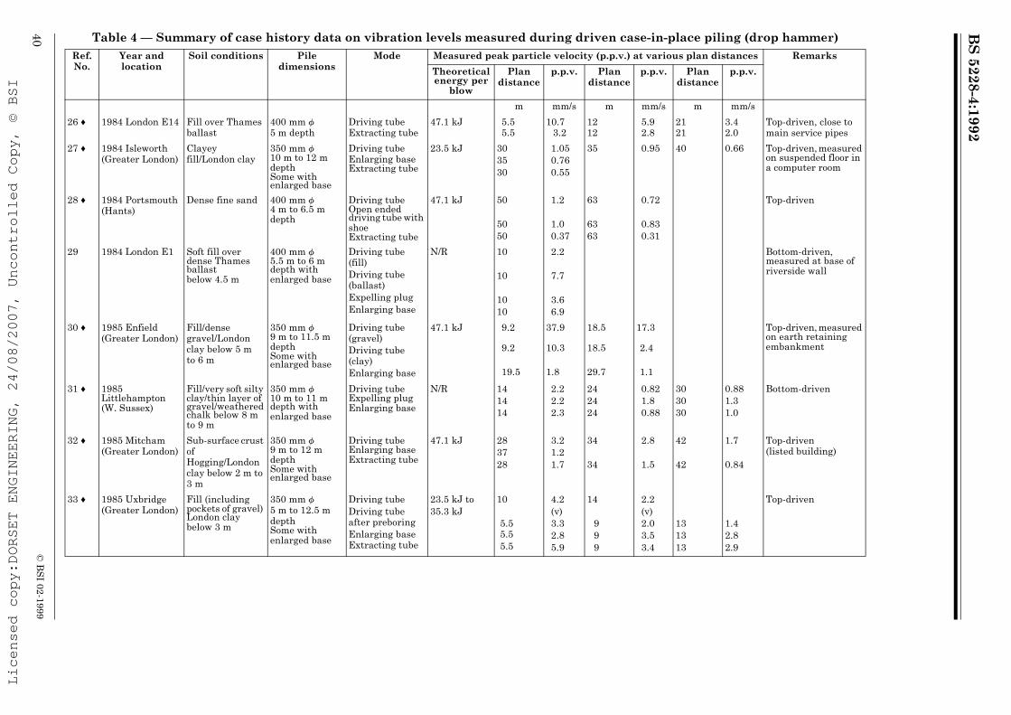
BS
5228-4:1992
40©
BS
I 02-1999
Table 4 — Summary of case history data on vibration levels measured during driven case-in-place piling (drop hammer)Ref. No.
Year and location
Soil conditions Pile dimensions
Mode Measured peak particle velocity (p.p.v.) at various plan distances Remarks
Theoretical energy per
blow
Plan distance
p.p.v. Plan distance
p.p.v. Plan distance
p.p.v.
m mm/s m mm/s m mm/s
26 ♦ 1984 London E14 Fill over Thames ballast
400 mm f5 m depth
Driving tubeExtracting tube
47.1 kJ 5.55.5
10.73.2
1212
5.92.8
2121
3.42.0
Top-driven, close to main service pipes
27 ♦ 1984 Isleworth (Greater London)
Clayeyfill/London clay
350 mm f 10 m to 12 m depth Some with enlarged base
Driving tube Enlarging base Extracting tube
23.5 kJ 303530
1.050.760.55
35 0.95 40 0.66 Top-driven, measured on suspended floor in a computer room
28 ♦ 1984 Portsmouth (Hants)
Dense fine sand 400 mm f 4 m to 6.5 m depth
Driving tube Open ended driving tube with shoe Extracting tube
47.1 kJ 50
5050
1.2
1.00.37
63
6363
0.72
0.830.31
Top-driven
29 1984 London E1 Soft fill over dense Thames ballast below 4.5 m
400 mm f 5.5 m to 6 m depth with enlarged base
Driving tube (fill)Driving tube (ballast)Expelling plugEnlarging base
N/R 10
10
1010
2.2
7.7
3.66.9
Bottom-driven, measured at base of riverside wall
30 ♦ 1985 Enfield (Greater London)
Fill/densegravel/London clay below 5 m to 6 m
350 mm f 9 m to 11.5 m depth Some with enlarged base
Driving tube (gravel)Driving tube (clay)Enlarging base
47.1 kJ 9.2
9.2
19.5
37.9
10.3
1.8
18.5
18.5
29.7
17.3
2.4
1.1
Top-driven, measured on earth retaining embankment
31 ♦ 1985 Littlehampton (W. Sussex)
Fill/very soft silty clay/thin layer of gravel/weathered chalk below 8 m to 9 m
350 mm f 10 m to 11 m depth with enlarged base
Driving tube Expelling plug Enlarging base
N/R 141414
2.22.22.3
242424
0.821.80.88
303030
0.881.31.0
Bottom-driven
32 ♦ 1985 Mitcham (Greater London)
Sub-surface crust ofHogging/London clay below 2 m to 3 m
350 mm f 9 m to 12 m depth Some with enlarged base
Driving tube Enlarging base Extracting tube
47.1 kJ 283728
3.21.21.7
34
34
2.8
1.5
42
42
1.7
0.84
Top-driven (listed building)
33 ♦ 1985 Uxbridge (Greater London)
Fill (including pockets of gravel) London clay below 3 m
350 mm f5 m to 12.5 mdepth Some with enlarged base
Driving tubeDriving tube after preboringEnlarging baseExtracting tube
23.5 kJ to35.3 kJ
10
5.55.55.5
4.2(v)3.32.85.9
14
999
2.2(v)2.03.53.4
131313
1.42.82.9
Top-driven
Licensed copy:DORSET ENGINEERING, 24/08/2007, Uncontrolled Copy, © BSI

BS
5228-4:1992
© B
SI 02-1999
41
Table 5 — Summary of case history data on vibration levels measured during dynamic consolidationRef. No.
Year and location
Soil conditions Tamping weight
Mode Measured peak particle velocity (p.p.v.) at various plan distances RemarksTheoretical energy per
blow
Plan distance
p.p.v. Plan distance
p.p.v. Plan distance
p.p.v.
t m mm/s m mm/s m mm/s34 1973 Corby
(Northants.)9 Pass 1 up to 1.59 MJ 25 3.0* 225 0.16*
Pass 2 up to 1.59 MJ 25 4.7* 120 0.33*35 1973 Belfast
(Antrim)Clay fill 10 1.47 MJ 8 42 26 3.6 44 1.75 Dropping onto
virgin ground1.96 MJ981 kJ
1414
1210
2525
3.22.9
4949
1.351.4
Dropping on to fill
36 1974 Teesside (Cleveland)
Hydraulic fill of clean sand with some pebbles
17 Pass 1Pass 2
2.50 MJ2.50 MJ
55
240177
1212
5367
2020
15.520.3
37 ♦ 1975 Canterbury (Kent)
Sand fill containing much fine silt
N/R 20 m drop15 m drop10 m drop
121012
16.520.515.5
202020
5.864.5
323228
2.73.32.2
38 ♦ 1975 Glasgow Govan (Strathclyde)
Old docks backfilled with well-graded permeable granular fill
15
15 (small base)2 (ball)
Pass 1Post-treatmentPost-treatmentPost-treatmentPost-treatmentPost-treatment
2.94 MJ2.94 MJ2.21 MJ1.47 MJ2.94 MJ392.4 kJ
151515151515
2230272735
9
303030303030
13.512101012
2.5
505050505050
98.38.56.58.02.0
Comparison between various tamping weights and drop heights
39 1975 Cwmbran (Gwent)
Loose fill in old clay quarry; depth 7 m to 20 m
N/R 20 m drop 27 5.8
40 1976 Port Talbot (W. Glamorgan)
Slag fill 15 2.94 MJ2.94 MJ
7575
2.17.2
250250
0.161.4
Measured at ground levelMeasured at top of 30 m high silo
41 ♦ 1978 London Old docks 10 Pass 1 981 kJ 24 8.9 40 4.6 70 2.0SE16 backfilled with
various materials1.96 MJ 24 13.5 40 11.2 70 2.0
1979 including 10 Later pass 1.96 MJ 10 52.3 22 8.9 65 2.2cohesive clay soils with
15 Later pass 2.94 MJ 16 15
1980 substantial voidage; depth
15 Pass 1 2.94 MJ 20 11.6 27 6.5 34 5.1
1981 9 m to 11 m 15 Pass 1 3.24 MJ 150 1.6
Licensed copy:DORSET ENGINEERING, 24/08/2007, Uncontrolled Copy, © BSI
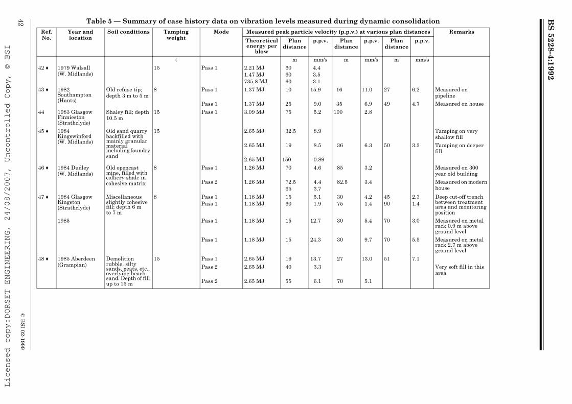
BS
5228-4:1992
42©
BS
I 02-1999
Table 5 — Summary of case history data on vibration levels measured during dynamic consolidation
Ref. No.
Year and location
Soil conditions Tamping weight
Mode Measured peak particle velocity (p.p.v.) at various plan distances Remarks
Theoretical energy per
blow
Plan distance
p.p.v. Plan distance
p.p.v. Plan distance
p.p.v.
t m mm/s m mm/s m mm/s
42 ♦ 1979 Walsall (W. Midlands)
15 Pass 1 2.21 MJ1.47 MJ735.8 MJ
606060
4.43.53.1
43 ♦ 1982 Southampton (Hants)
Old refuse tip; depth 3 m to 5 m
8 Pass 1 1.37 MJ 10 15.9 16 11.0 27 6.2 Measured on pipeline
Pass 1 1.37 MJ 25 9.0 35 6.9 49 4.7 Measured on house
44 1983 Glasgow Finnieston (Strathclyde)
Shaley fill; depth 10.5 m
15 Pass 1 3.09 MJ 75 5.2 100 2.8
45 ♦ 1984 Kingswinford (W. Midlands)
Old sand quarry backfilled with mainly granular material including foundry sand
15 2.65 MJ 32.5 8.9 Tamping on very shallow fill
2.65 MJ 19 8.5 36 6.3 50 3.3 Tamping on deeper fill
2.65 MJ 150 0.89
46 ♦ 1984 Dudley (W. Midlands)
Old opencast mine, filled with colliery shale in cohesive matrix
8 Pass 1 1.26 MJ 70 4.6 85 3.2 Measured on 300 year old building
Pass 2 1.26 MJ 72.565
4.43.7
82.5 3.4 Measured on modern house
47 ♦ 1984 Glasgow Kingston (Strathclyde)
Miscellaneous slightly cohesive fill; depth 6 m to 7 m
8 Pass 1Pass 1
1.18 MJ1.18 MJ
1560
5.11.9
3075
4.21.4
4590
2.31.4
Deep cut-off trench between treatment area and monitoring position
1985 Pass 1 1.18 MJ 15 12.7 30 5.4 70 3.0 Measured on metal rack 0.9 m above ground level
Pass 1 1.18 MJ 15 24.3 30 9.7 70 5.5 Measured on metal rack 2.7 m above ground level
48 ♦ 1985 Aberdeen (Grampian)
Demolition rubble, silty sands, peats, etc., overlying beach sand. Depth of fill up to 15 m
15 Pass 1 2.65 MJ 19 13.7 27 13.0 51 7.1
Pass 2 2.65 MJ 40 3.3 Very soft fill in this area
Pass 2 2.65 MJ 55 6.1 70 5.1
Licensed copy:DORSET ENGINEERING, 24/08/2007, Uncontrolled Copy, © BSI

BS
5228-4:1992
© B
SI 02-1999
43
Table 5 — Summary of case history data on vibration levels measured during dynamic consolidation
Ref. No.
Year and location
Soil conditions Tamping weight
Mode Measured peak particle velocity (p.p.v.) at various plan distances Remarks
Theoretical energy per
blow
Plan distance
p.p.v. Plan distance
p.p.v. Plan distance
p.p.v.
t m mm/s m mm/s m mm/s
49 ♦ 1985 Gravesend (Kent)
Old domestic fill including bottles overlying Thanet sands and chalk. Depth of fill 1.5 m to 6 m
8 Pass 1Pass 2
1.26 MJ1.26 MJ
5050
2.82.6
50 ♦ 1985 Preston (Lancs)
Old brickworks clay pit backfilled with loose ash, bottles, etc. Depth of fill 1 m to 5.5 m
15 Pass 1Pass 2
2.94 MJ1.47 MJ
3838
6.58.1
Fill very shallow
51 ♦ 1985 Exeter (Devon)
Old quarry backfilled with rubble, clays and miscellaneous waste overlying hard shale. Depth of fill 4 m to 12 m
8 Pass 1 1.26 MJ 30 4.2
Licensed copy:DORSET ENGINEERING, 24/08/2007, Uncontrolled Copy, © BSI

BS
5228-4:1992
44©
BS
I 02-1999
Table 6 — Summary of case history data on vibration levels measured during vibroflotation/vibroreplacement
Ref. No.
Year and location
Soil conditions Depth of treatment
Mode Measured peak particle velocity (p.p.v.) at various plan distances Remarks
Theoretical energy per
cycle
Plan distance
p.p.v. Plan distance
p.p.v. Plan distance
p.p.v.
m kJ m mm/s m mm/s m mm/s
52 1973 Newport (Gwent)
Demolition rubble in old basements
N/R N/R 3.0 33
7.9*7.3*
66
4.5*6.3*
1212
2.7*1.9*
VerticalHorizontal
53 1973 Manchester Central (Greater Manchester)
Unspecified fill N/R N/R 3.0 3.5 5.1* Horizontal
54 ♦ 1974 Worcester (Hereford and Worcester)
N/R N/R N/R 1.64 2.4 2.0
55 ♦ 1974 London E9 N/R 3 Airflush 3.0 6.5
13.0
12.7
10.5
Measured on ground surfaceMeasured at mid height of 3 m high brick boundary wall
56 ♦ 1974 Sandgate (Kent)
N/R N/R N/R 3.0 2 24.0 5 10.0 20 1.6
57 ♦ 1975 Hemel Hempstead (Herts)
Loose chalk fill 6 N/R 3.0 1 18.0 2 15.0 2.9 5.0 Vertical
6.7 2.5 14.5 0.6 Vertical
58 ♦ 1975 Oxford (Oxon)
Disused limestone quarry backfilled with rubble
3 to 4 N/R 3.0 12 2.6
59 1975 Port Talbot (W. Glamorgan)
Soft alluvium with surface crust
9.2 Waterflush 3.0 8 3.2 Vertical
60 1976 Bradford (West Yorks)
N/R N/R N/R 3.0 0.6 19 1.2 8
61 ♦ 1976 Sutton Coldfield (W. Midlands)
Backfilled sand quarry
3 to 4 Airflush 3.0 25 1.4
62 ♦ 1976 Oxford (Oxon)
As for no. 58 3 to 4 N/R 3.0 15 1.9 20 1.1
Licensed copy:DORSET ENGINEERING, 24/08/2007, Uncontrolled Copy, © BSI
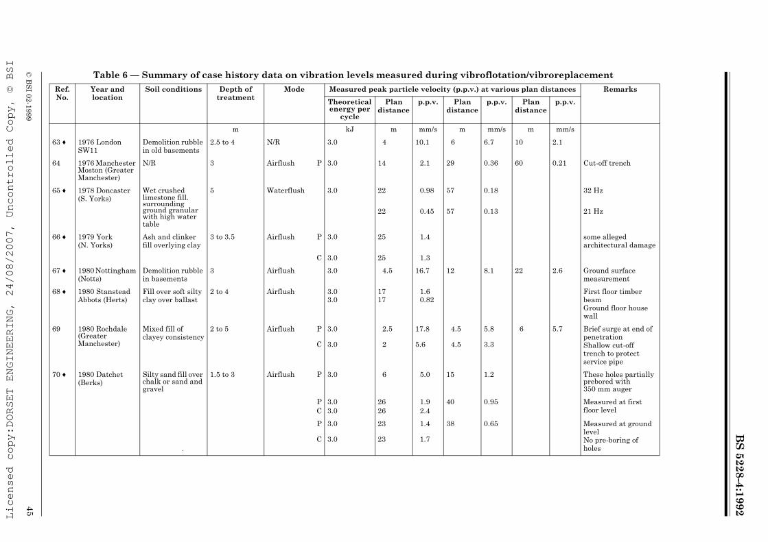
BS
5228-4:1992
© B
SI 02-1999
45
Table 6 — Summary of case history data on vibration levels measured during vibroflotation/vibroreplacement
Ref. No.
Year and location
Soil conditions Depth of treatment
Mode Measured peak particle velocity (p.p.v.) at various plan distances Remarks
Theoretical energy per
cycle
Plan distance
p.p.v. Plan distance
p.p.v. Plan distance
p.p.v.
m kJ m mm/s m mm/s m mm/s
63 ♦ 1976 London SW11
Demolition rubble in old basements
2.5 to 4 N/R 3.0 4 10.1 6 6.7 10 2.1
64 1976 Manchester Moston (Greater Manchester)
N/R 3 Airflush P 3.0 14 2.1 29 0.36 60 0.21 Cut-off trench
65 ♦ 1978 Doncaster (S. Yorks)
Wet crushed limestone fill. surrounding ground granular with high water table
5 Waterflush 3.0 22 0.98 57 0.18 32 Hz
22 0.45 57 0.13 21 Hz
66 ♦ 1979 York (N. Yorks)
Ash and clinker fill overlying clay
3 to 3.5 Airflush P 3.0 25 1.4 some alleged architectural damage
C 3.0 25 1.3
67 ♦ 1980 Nottingham (Notts)
Demolition rubble in basements
3 Airflush 3.0 4.5 16.7 12 8.1 22 2.6 Ground surface measurement
68 ♦ 1980 Stanstead Abbots (Herts)
Fill over soft silty clay over ballast
2 to 4 Airflush 3.03.0
1717
1.60.82
First floor timber beamGround floor house wall
69 1980 Rochdale (Greater Manchester)
Mixed fill of clayey consistency
2 to 5 Airflush P
C
3.0
3.0
2.5
2
17.8
5.6
4.5
4.5
5.8
3.3
6 5.7 Brief surge at end of penetrationShallow cut-off trench to protect service pipe
70 ♦ 1980 Datchet (Berks)
Silty sand fill over chalk or sand and gravel
1.5 to 3 Airflush P 3.0 6 5.0 15 1.2 These holes partially prebored with 350 mm auger
PC
3.03.0
2626
1.92.4
40 0.95 Measured at first floor level
P
C
3.0
3.0
23
23
1.4
1.7
38 0.65 Measured at ground levelNo pre-boring of holes
Licensed copy:DORSET ENGINEERING, 24/08/2007, Uncontrolled Copy, © BSI

BS
5228-4:1992
46©
BS
I 02-1999
Table 6 — Summary of case history data on vibration levels measured during vibroflotation/vibroreplacement
Ref. No.
Year and location
Soil conditions Depth of treatment
Mode Measured peak particle velocity (p.p.v.) at various plan distances Remarks
Theoretical energy per
cycle
Plan distance
p.p.v. Plan distance
p.p.v. Plan distance
p.p.v.
m kJ m mm/s m mm/s m mm/s
71 1980 Belfast (Antrim)
Weak sandy clay Up to 7 Airflush
Waterflush
PCPC
3.03.03.03.0
53.53.83.8
2.95.01.41.1
8.356.66.6
1.92.40.780.81
8.3 1.5
72 1981 Brigg (S. Humberside)
Fine silty sand 3 Waterflush PC
1.641.64
1.51.5
5.43.5
2.52.5
3.13.0
55
2.12.5
73 1981 Huddersfield (W. Yorks)
Ash and brick rubble fill
3 to 3.5 Airflush PCPC
3.03.03.03.0
2.52.55.55.5
34.748.0
7.58.4
4.64.67.67.6
19.718.2
3.95.4
11.811.8
8.73.8
Ground surface measurementsMeasured on underground service pipe
74 ♦ 1981 Cardiff (S. Glamorgan)
Backfilled railway cutting; slag fill
2 to 3 Airflush PC
3.03.0
66
3.53.3
2020
0.570.78
75 1982 Birmingham Hockley (W. Midlands)
Demolition rubble in collapsed basements
3 Airflush PC
3.03.0
55
2.63.5
88
1.61.8
1111
1.10.98
Measured on old brick sewer
76 ♦ 1983 Datchet (Berks)
Miscellaneous fill including dense fine sand and very loose sand
3 Airflush P 3.0 8 4.9 12 3.8 20 1.3 Measurements on end terrace house with existing defectsC 3.0 8 2.0 12 3.2 20 1.8
77 1983 Rugeley (Staffs)
Demolition rubble fill to 3 m over sands and gravels
3 Airflush PCPC
3.03.03.03.0
6644
16.18.6
35.225.7
1010
7.56.5
8.65.84.58.6
22221616
2.01.91.41.3
Ground surface measurementsMeasured on top of retaining wall
78 ♦ 1983 Tewkesbury (Glos)
Made ground including raised shingle
3 Airflush PCPC
3.03.03.03.0
663.53.5
12.59.1
22.325.7
15151010
2.93.1
15.511.6
2727
0.870.87
Measurements on free-standing manhole surround
79 ♦ 1983 Newcastle-upon-Tyne (Tyne and wear)
Ash and brick rubble fill
2.5 to 6 Airflush PP
3.03.0
5.511
2.52.6
7.5 2.0 15 1.5 Encountered buried obstruction
Licensed copy:DORSET ENGINEERING, 24/08/2007, Uncontrolled Copy, © BSI
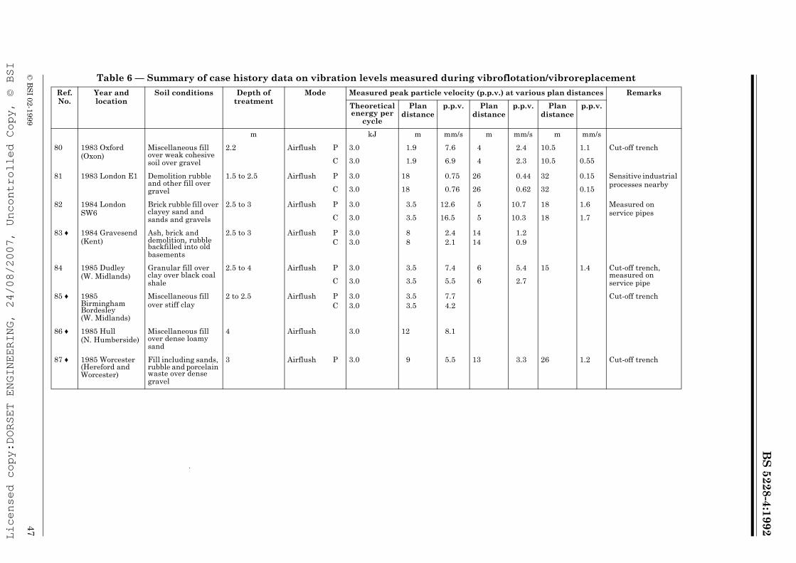
BS
5228-4:1992
© B
SI 02-1999
47
Table 6 — Summary of case history data on vibration levels measured during vibroflotation/vibroreplacement
Ref. No.
Year and location
Soil conditions Depth of treatment
Mode Measured peak particle velocity (p.p.v.) at various plan distances Remarks
Theoretical energy per
cycle
Plan distance
p.p.v. Plan distance
p.p.v. Plan distance
p.p.v.
m kJ m mm/s m mm/s m mm/s
80 1983 Oxford (Oxon)
Miscellaneous fill over weak cohesive soil over gravel
2.2 Airflush P 3.0 1.9 7.6 4 2.4 10.5 1.1 Cut-off trench
C 3.0 1.9 6.9 4 2.3 10.5 0.55
81 1983 London E1 Demolition rubble and other fill over gravel
1.5 to 2.5 Airflush P 3.0 18 0.75 26 0.44 32 0.15 Sensitive industrial processes nearby
C 3.0 18 0.76 26 0.62 32 0.15
82 1984 London SW6
Brick rubble fill over clayey sand and sands and gravels
2.5 to 3 Airflush P 3.0 3.5 12.6 5 10.7 18 1.6 Measured on service pipes
C 3.0 3.5 16.5 5 10.3 18 1.7
83 ♦ 1984 Gravesend (Kent)
Ash, brick and demolition, rubble backfilled into old basements
2.5 to 3 Airflush PC
3.03.0
88
2.42.1
1414
1.20.9
84 1985 Dudley (W. Midlands)
Granular fill over clay over black coal shale
2.5 to 4 Airflush P 3.0 3.5 7.4 6 5.4 15 1.4 Cut-off trench, measured on service pipeC 3.0 3.5 5.5 6 2.7
85 ♦ 1985 Birmingham Bordesley (W. Midlands)
Miscellaneous fill over stiff clay
2 to 2.5 Airflush PC
3.03.0
3.53.5
7.74.2
Cut-off trench
86 ♦ 1985 Hull (N. Humberside)
Miscellaneous fill over dense loamy sand
4 Airflush 3.0 12 8.1
87 ♦ 1985 Worcester (Hereford and Worcester)
Fill including sands, rubble and porcelain waste over dense gravel
3 Airflush P 3.0 9 5.5 13 3.3 26 1.2 Cut-off trench
Licensed copy:DORSET ENGINEERING, 24/08/2007, Uncontrolled Copy, © BSI
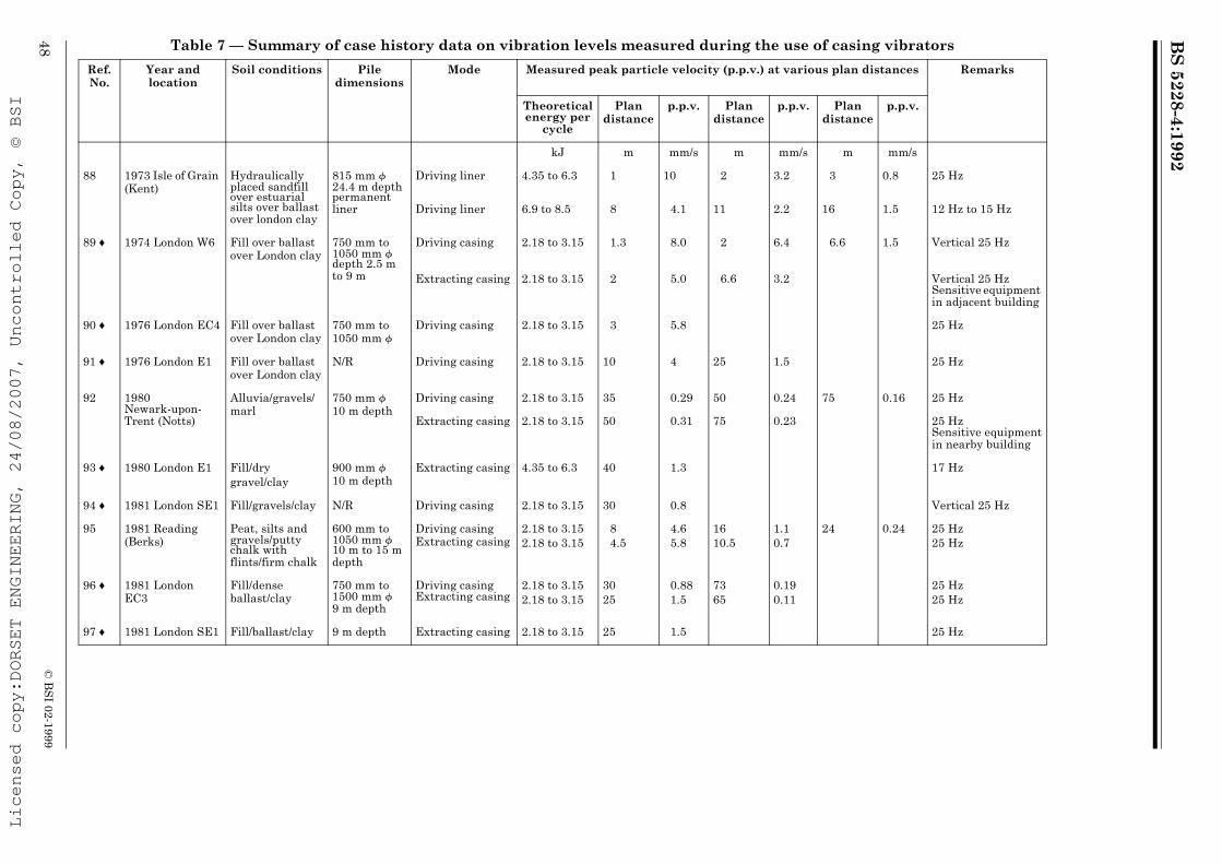
BS
5228-4:1992
48©
BS
I 02-1999
Table 7 — Summary of case history data on vibration levels measured during the use of casing vibrators
Ref. No.
Year and location
Soil conditions Pile dimensions
Mode Measured peak particle velocity (p.p.v.) at various plan distances Remarks
Theoretical energy per
cycle
Plan distance
p.p.v. Plan distance
p.p.v. Plan distance
p.p.v.
kJ m mm/s m mm/s m mm/s
88 1973 Isle of Grain (Kent)
Hydraulically placed sandfill over estuarial silts over ballast over london clay
815 mm f 24.4 m depth permanent liner
Driving liner 4.35 to 6.3 1 10 2 3.2 3 0.8 25 Hz
Driving liner 6.9 to 8.5 8 4.1 11 2.2 16 1.5 12 Hz to 15 Hz
89 ♦ 1974 London W6 Fill over ballast over London clay
750 mm to 1050 mm f depth 2.5 m to 9 m
Driving casing 2.18 to 3.15 1.3 8.0 2 6.4 6.6 1.5 Vertical 25 Hz
Extracting casing 2.18 to 3.15 2 5.0 6.6 3.2 Vertical 25 Hz Sensitive equipment in adjacent building
90 ♦ 1976 London EC4 Fill over ballast over London clay
750 mm to 1050 mm f
Driving casing 2.18 to 3.15 3 5.8 25 Hz
91 ♦ 1976 London E1 Fill over ballast over London clay
N/R Driving casing 2.18 to 3.15 10 4 25 1.5 25 Hz
92 1980 Newark-upon-Trent (Notts)
Alluvia/gravels/marl
750 mm f 10 m depth
Driving casing 2.18 to 3.15 35 0.29 50 0.24 75 0.16 25 Hz
Extracting casing 2.18 to 3.15 50 0.31 75 0.23 25 Hz Sensitive equipment in nearby building
93 ♦ 1980 London E1 Fill/drygravel/clay
900 mm f 10 m depth
Extracting casing 4.35 to 6.3 40 1.3 17 Hz
94 ♦ 1981 London SE1 Fill/gravels/clay N/R Driving casing 2.18 to 3.15 30 0.8 Vertical 25 Hz
95 1981 Reading (Berks)
Peat, silts and gravels/putty chalk with flints/firm chalk
600 mm to 1050 mm f 10 m to 15 m depth
Driving casing Extracting casing
2.18 to 3.152.18 to 3.15
84.5
4.65.8
1610.5
1.10.7
24 0.24 25 Hz25 Hz
96 ♦ 1981 London EC3
Fill/dense ballast/clay
750 mm to 1500 mm f 9 m depth
Driving casing Extracting casing
2.18 to 3.152.18 to 3.15
3025
0.881.5
7365
0.190.11
25 Hz25 Hz
97 ♦ 1981 London SE1 Fill/ballast/clay 9 m depth Extracting casing 2.18 to 3.15 25 1.5 25 Hz
Licensed copy:DORSET ENGINEERING, 24/08/2007, Uncontrolled Copy, © BSI

BS
5228-4:1992
© B
SI 02-1999
49
Table 7 — Summary of case history data on vibration levels measured during the use of casing vibrators
Ref. No.
Year and location
Soil conditions Pile dimensions Mode Measured peak particle velocity (p.p.v.) at various plan distances Remarks
Theoretical energy per
cycle
Plan distance
p.p.v. Plan distance
p.p.v. Plan distance
p.p.v.
kJ m mm/s m mm/s m mm/s
98 1984 Barrow-in-Furness (Cumbria)
Hydraulically placed sandfill/boulder clay marl
1 350 mm f 8 m depth concentric with 1 200 mm f 17.5 m depth permanent liner
Driving-outer casing
26.1 19 13.1 Warning up 10 Hz
15.35 19 9.2 17 Hz
99 ♦ 1985 Hatfield (Herts)
Clay over gravels
90 mm f 15 m depth anchor casing
Driving casing 1.25 11 0.8 Anchor casings driven at 30° to horizontalExtracting casing 1.25 8 1.3 11 0.8
Licensed copy:DORSET ENGINEERING, 24/08/2007, Uncontrolled Copy, © BSI

BS
5228-4:1992
50©
BS
I 02-1999
Table 8 — Summary of case history data on vibration levels measured during rotary bored piling (including casing dollies)
Ref. No.
Year and location
Soil conditions Pile dimensions
Mode Measured peak particle velocity (p.p.v.) at various plan distances Remarks
Theoretical energy per
blow
Plan distance
p.p.v. Plan distance
p.p.v. Plan distance
p.p.v.
kJ m mm/s m mm/s m mm/s
100 ♦ 1974 London W6 Fill/gravel/London clay
N/R Driving casing With 3 t dolly
77
3.21.0
HorizontalVertical
101 1981 London EC3 Fill/denseballast/London clay
1 050 mm f Augering 20 0.05 Listed building nearby
Auger hitting base of hole
20 0.23
102 1982 Cheltenham (Glos.)
Fill/wet sand/lias clay
900 mm f Augering Hammering casing with Kelly bar
9 0.2 Listed building adjacent to site
9 0.8
103 1983 Romford (Greater London)
Fill clay 350 mm f 14.5 m depth
AugeringDollying casingAuger hitting base of holeSpinning off
11.81010
1010
0.381.1
0.960.57
2020
20
0.30.55
0.44
30 0.032 t dolly
104 1985 London W1 Fill/sand/clay 500 mm f AugeringAuger hitting base of holeMudding inSpinning offDollying casing 11.8
10
14101010
0.4
0.30.30.31.0
15
2614
14
0.1
0.10.2
0.8
26 0.02
2 t dolly
105 1985 St. Albans (Herts)
Sands and gravels over chalk
600 mm f 12 m depth
AugeringAuger hitting base of holeSpinning off
3.5
3.56
0.23
2.40.08
8
88
0.04
1.70.06
106 1985 Portland (Dorset)
6 m of soft ground over rock
600 mm f 7 m depth
AugeringSurging casing Twisting in casingSpinning offBoring with rock auger
55
55
5
0.540.36
0.220.42
0.43
Sensitive equipment in adjacent building
107 1985 Uxbridge (Greater London)
Fill including pockets of gravel over London clay
350 mm f 7 m depth
Augering 5.5 0.13 Preboring for a driven pile
Licensed copy:DORSET ENGINEERING, 24/08/2007, Uncontrolled Copy, © BSI

BS
5228-4:1992
© B
SI 02-1999
51
Table 9 — Summary of case history data on vibration levels measured during tripod bored piling
Ref. No.
Year and location
Soil conditions Pile dimensions Mode Measured peak particle velocity (p.p.v.) at various plan distances Remarks
Theoretical energy per
blow
Plan distance
p.p.v. Plan distance
p.p.v. Plan distance
p.p.v.
kJ m mm/s m mm/s m mm/s
C1 ♦ 1971 London WC2
Overburden over London clay
N/R Driving casing N/R 1 12.5
C2 ♦ 1971 London SW1
Sand and gravel over London clay
500 mm f 17 m depth
N/R N/R 11 2.6 42 0.31
C3 ♦ Bury (Greater Manchester)
Sand andgravel/soft silty clay/hard glacial till
300 mm f N/R N/R 15 4.0
Licensed copy:DORSET ENGINEERING, 24/08/2007, Uncontrolled Copy, © BSI

BS
5228-4:1992
52©
BS
I 02-1999
Table 10 — Summary of case history data on vibration levels measured during driven sheet steel pilingRef. No.
Year and location
Soil conditions Pile dimensions
Mode Measured peak particle velocity (p.p.v.) at various plan distances Remarks
Theoretical energy per
blow
Plan distance
p.p.v. Plan distance
p.p.v. Plan distance
p.p.v.
kJ m mm/s m mm/s m mm/s
C4 ♦ N/R Aldermaston (Berks)
3 m to 4 m sandy gravel over London clay
N/R Air hammer driving sheets
15 12 0.05 Vertical
C5 ♦ N/R Bridlington (Humberside)
4 m to 5 m soft saturated sand over soft to firm clay
N/R
N/R
Air hammer driving sheetsExtracting sheets
6.4
7.6
6
6
1.1
0.44
225 Blows per min
150 Blows per min
C6 ♦ N/R CanveyIsland (Essex)
Clay/soft siltyclay/silty sand; high water table
Fordingham3 N 8 m depth
Drop hammerdriving sheets
4.5 thammer drop N/R
3535
3.00.5
VerticalHorizontal
C7 ♦ N/R Montrose (Tayside)
N/R Larssen Driving sheets 32 to 73 11.7 4 Vertical
C8 ♦ 1971 London WC2
Overburden/London clay
N/R Diesel hammer driving sheets Air hammer driving sheets
N/R 1 20
N/R 1 10
C9 ♦ 1974 Lancashire Fill/firm to stiff boulderclay/sandy stony clay/firm boulder clay
N/R Driving sheets 33 0.89* Horizontal
C10 1978 Crail (Fife) Clay/rock N/R Drop hammer driving sheets 39.2 15
150.79*0.48
Vertical, pile in clayVertical, pile on rock
C11 ♦ N/R Hull (Humberside)
Fill/6 m alluvium/4 m to 6 m peat, clay, sand andsilt/1.3 m sand and gravel/5 m stiff clay/9 m dense sand/hard chalk
Larssen no. 6 34 m depth Penetration 1 m into chalk; 27 m in total
Diesel hammer driving sheets
71.6 to 143.23030
1.10.35
130130
0.10.1
250250
0.0250.015
Horizontal radialHorizontal
30 0.6 130 0.1 250 0.025 Transverse vertical
Licensed copy:DORSET ENGINEERING, 24/08/2007, Uncontrolled Copy, © BSI

BS
5228-4:1992
© B
SI 02-1999
53
Table 10 — Summary of case history data on vibration levels measured during driven sheet steel pilingRef. No.
Year and location
Soil conditions Pile dimensions
Mode Measured peak particle velocity (p.p.v.) at various plan distances Remarks
Theoretical energy per
blow
Plan distance
p.p.v. Plan distance
p.p.v. Plan distance
p.p.v.
kJ m mm/s m mm/s m mm/s
C12 ♦ 1978 Hazel Grove (Greater Manchester
Stiff clay/dense sand including clay bands
Frodingham 2 N Drop hammer driving sheets
19.9 11 16 26 12.5 54 2.6
C13 ♦ 1978 Oldham (Greater Manchester)
N/R N/R Diesel hammer driving sheets
N/R 60 2.5 + Vertical
C14 N/R Cambridge (Cambs)
Loose to medium sands over clay
N/R Driving sheets N/R 22
102
VerticalHorizontal
C15 ♦ 1979 Molesey (Surrey)
Gravel over London clay
N/R Diesel hammer driving sheets N/R 5
513.540.4
on bungalowon ground surface
C16 1979 Rochdale (Greater Manchester)
N/R N/R Driving sheets N/R 6 1.9
C17 N/R Cambridge (Cambs)
Fill/sand and gravel/gault clay
Frodingham 1 B 6 m depth
Drop hammer driving sheets
13.5 1 9.1*
C18 1980 Newton Heath (Greater Manchester)
N/R N/R Driving sheets N/R 300 0.015 Vertical
C19 1981 Denton (Greater Manchester)
Firm sandy glacial till
14 m depth Diesel hammer driving sheets
N/R 0.9 15 Vertical
Licensed copy:DORSET ENGINEERING, 24/08/2007, Uncontrolled Copy, © BSI

BS
5228-4:1992
54©
BS
I 02-1999
Table 11 — Summary of case history data on vibration levels measured during driving of bearing piles
Ref. No.
Year and location
Soil conditions Pile dimensions
Mode Measured peak particle velocity (p.p.v.) at various plan distances Remarks
Theoretical energy per
blow
Plan distance
p.p.v. Plan distance
p.p.v. Plan distance
p.p.v.
kJ m mm/s m mm/s m mm/s
C20 N/R Glasgow Cowcaddens (Strathclyde)
3 m fill, blaes, clay and boulders over 8 m soft to firm silty clay over sandstone
305 mm × 305 mmSteel H-pile
4 t drop hammer driving pile
N/R 13 0.19* Vertical
C21 N/R Drax (N.Yorks)
Granular fill, lacustrine deposits, sand, sandstone
Precast concrete 400 mm × 400 mm
Diesel and drop hammers driving piles
24.5 to 88.2 3 13 Vertical
C22 N/R Kinneil (Central)
N/R N/R Driving pile N/R 6 5.2 +
C23 N/R Leeds (W. Yorks)
4 m fill/2 m alluvial granular soils/rock
Drivencast-in-place dimensions N/R
Driving pile N/R 12 5.1 23 1.4 When driven 1.5 m
C24 ♦ N/R Middlesbrough (Cleveland)
22 m firm becoming stiff boulder clay over marl
Drivencast-in-place dimensions N/R
Driving pile N/R 12 11.6 30 4.7 45 1.45
C25 N/R Ravenscraig (Strathclyde)
N/R 305 mm × 305 mmSteel H-pile
Diesel hammer driving pile
N/R 25 0.13 +
C26 N/R Reading (Berks)
N/R Drivencast-in-place dimensions N/R
Driving pile N/R 6090
0.070.12
Measured on fifth floor of office building
C27 1968 Wylfa (Gwynedd)
Rockfill and clay over mica schist
Steel H-pile Diesel hammer driving pile
N/R 1 18 Vertical
C28 1969 Ince (Cheshire)
Alluvial peat and clay, boulder clay, sand, bunter sandstone
305 mm × 305 mmSteel H-pile
Diesel hammer driving pile
43.4 8 1.4
Licensed copy:DORSET ENGINEERING, 24/08/2007, Uncontrolled Copy, © BSI

BS
5228-4:1992
© B
SI 02-1999
55
Table 11 — Summary of case history data on vibration levels measured during driving of bearing piles
Ref. No.
Year and location
Soil conditions Pile dimensions
Mode Measured peak particle velocity (p.p.v.) at various plan distances Remarks
Theoretical energy per
blow
Plan distance
p.p.v. Plan distance
p.p.v. Plan distance
p.p.v.
kJ m mm/s m mm/s m mm/s
C29 ♦ 1972 Derby (Derbys)
N/R 400 mm to 450 mm f Drivencast-in-place
Driving pile tube N/R 15 2.2
C30 ♦ 1972/3 Bristol (Avon)
Fill and alluvium over keuper marl
Simulation test for driven shell piling
Dropping test weight on ground
58.8 25 0.7 Vertical on ground
C31 ♦ 1977 Southampton (Hants)
2 m to 3 m granular fill over bracklesham beds, very compact clayey fine sand
275 mm × 275 mm × 9 m depth pre-cast concrete piles
Drop hammer driving pile
N/R 25 2.45 Holes prebored to 3 m depth
C32 ♦ 1977 Middlesbrough (Cleveland)
Made ground/9 m to 12 m firm to stiff laminated clay/4 m to 6 m glacial till/hard keuper marl
480 mm fCast-in-place piling length N/R
Drop hammer driving pile tube
294.2 27 7.4 + 55 3.3 + Horizontal on ground
C33 ♦ 1977/78 Kings Lynn (Norfolk)
10.4 m soft clayey silt and peat/5 m stiff kimmeredge clay/hard laminated kimmeredge clay
406 mm f Driven cased pile, depth N/R
Drop hammer driving pile
36.8 14 0.3 Vertical
C34 1978 South Shields (Tyne and Wear)
Loose to medium sand and silt/soft to firm laminated clay/stiff boulder clay/medium to dense sand and gravel over mudstone at 21 m to 25 m depth
305 mm × 305 mmSteel H-pile,depth N/R
Diesel hammer driving pile
36.3 1.1 9.5
Licensed copy:DORSET ENGINEERING, 24/08/2007, Uncontrolled Copy, © BSI

BS
5228-4:1992
56©
BS
I 02-1999
Table 11 — Summary of case history data on vibration levels measured during driving of bearing piles
Ref. No.
Year and location
Soil conditions Pile dimensions
Mode Measured peak particle velocity (p.p.v.) at various plan distances Remarks
Theoretical energy per
blow
Plan distance
p.p.v. Plan distance
p.p.v. Plan distance
p.p.v.
kJ m mm/s m mm/s m mm/s
C35 ♦ 1978/9 Hull (Humber side)
N/R Raking precast concrete piles, dimensions N/R
Drop hammer driving pile
N/R 20 0.51
C36 ♦ 1979 London SE8
N/R Driven shell piles, dimensions N/R
Drop hammer driving pile
N/R 16.5 2.1 33 1.95 46 0.9
C37 1980 Caernarvon (Gwynedd)
Fill/gravels and clayey silts/hard glacial till
Drivencast-in-place, dimensions N/R
Driving pile tube N/R 2.5 18.6 5 to 10 5.5 Distances N/R precisely
C38 ♦ 1980 Haxby (N.Yorks)
1.9 m to 3.5 m Clayey sandy fill over soft to firm laminated clay
Drivencast-in-place, depth 4 m to 5.5 m, f N/R
Driving pile tube N/R 3.8 25.0 5.5 22.0
C39 ♦ 1980 Leatherhead (Surrey)
N/R Type and dimensions N/R
Driving pile N/R 50
50
1.25
2.5
Measured on ground floorMeasured in middle of 1st floor
C40 ♦ 1980 Middlesbrough (Cleveland)
N/R Drivencast-in-place, dimensions N/R
Driving pile tube N/R 11 28.9 18 13.8 48 3.1
C41 1981 Grangemouth (Central)
Soft alluvium Driven shell piles, 450 mm × 36 m depth
Drop hammer driving pile
29.4 4.5 2.1 9.5 1.2
C42 ♦ 1981 London W6 4 m fill/2 m ballast/London clay
Drivencast-in-place, dimensions N/R
Driving pile tube N/R 12 6.7
C43 1981 Winchester (Hants)
4 m to 5 m made ground/gravel/chalk
Bottom driven cased pile 10.5 m depth
Driving pile N/R 2 to 3 3 to 4 Occasional peaks up to 30 mm/s
Licensed copy:DORSET ENGINEERING, 24/08/2007, Uncontrolled Copy, © BSI

BS
5228-4:1992
© B
SI 02-1999
57
Table 12 — Summary of case history data on vibration levels measured during use of vibratory pile drivers
Ref. No.
Year and location
Soil conditions Pile dimensions
Mode Measured peak particle velocity (p.p.v.) at various plan distances Remarks
Theoretical energy per
blow
Plan distance
p.p.v. Plan distance
p.p.v. Plan distance
p.p.v.
kJ m mm/s m mm/s m mm/s
C44 ♦ N/R Bridlington (Humberside)
4 m to 5 m soft saturated sand over soft to firm clay
Sheet steel piling, dimensions N/R
Driving or extracting
N/R 6 2.6 8 2.2 27.5 Hz
C45 ♦ N/R Glasgow Cowcaddens (Strathclyde)
3 m fill, blaes, clay and boulders over 8 m soft to firm silty clay over sandstone
450 mm f casing, depthN/R
Driving casing 2.18 to 3.15 13 1.4* 25 Hz
C46 ♦ N/R New Haw (Surrey)
1 m fill/8 m to 12 m dense fine and medium sand with silty clay lenses (Bagshot), Claygate beds, London clay
Casing dimensions N/R
Driving casing N/R 7 44 10 23.5 17.5 18.5 25 Hz
Extracting casing N/R 7 53 15 27 25 2.9 25 Hz
C47 1968 Drax (N. Yorks)
N/R N/R Warming up to drive pile (Resonant pile driver)
N/R 2 10 to 15
70 Hz to 80 Hz
C48 ♦ 1968 Hastings (E. Sussex)
4 m clay/8 m peat/2.5 mclay/1 m sandy silt with gravel/6 m stiff clay (Hastings beds)/mudstone and siltstone
N/R Resonant pile driver
N/R 6 2.5 70 Hz to 80 Hz
C49 ♦ 1972 London EC4
Sand and gravel over London clay
N/R Driving pile 2.18 to 3.15 10 0.55 25 Hz
C50 ♦ 1975 Milngavie (Strathclyde)
N/R casings, dimensions N/R
Driving casing Extracting casing
N/RN/R
55
2.52.0
27.5 Hz
Licensed copy:DORSET ENGINEERING, 24/08/2007, Uncontrolled Copy, © BSI
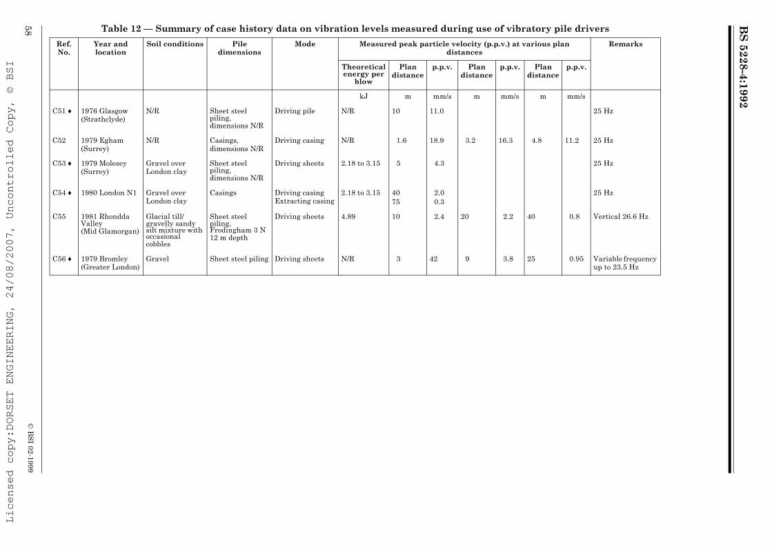
BS
5228-4:1992
58©
BS
I 02-1999
Table 12 — Summary of case history data on vibration levels measured during use of vibratory pile drivers
Ref. No.
Year and location
Soil conditions Pile dimensions
Mode Measured peak particle velocity (p.p.v.) at various plan distances
Remarks
Theoretical energy per
blow
Plan distance
p.p.v. Plan distance
p.p.v. Plan distance
p.p.v.
kJ m mm/s m mm/s m mm/s
C51 ♦ 1976 Glasgow (Strathclyde)
N/R Sheet steel piling, dimensions N/R
Driving pile N/R 10 11.0 25 Hz
C52 1979 Egham (Surrey)
N/R Casings, dimensions N/R
Driving casing N/R 1.6 18.9 3.2 16.3 4.8 11.2 25 Hz
C53 ♦ 1979 Molesey (Surrey)
Gravel over London clay
Sheet steel piling, dimensions N/R
Driving sheets 2.18 to 3.15 5 4.3 25 Hz
C54 ♦ 1980 London N1 Gravel over London clay
Casings Driving casing Extracting casing
2.18 to 3.15 4075
2.00.3
25 Hz
C55 1981 Rhondda Valley (Mid Glamorgan)
Glacial till/gravelly sandy silt mixture with occasional cobbles
Sheet steel piling, Frodingham 3 N 12 m depth
Driving sheets 4.89 10 2.4 20 2.2 40 0.8 Vertical 26.6 Hz
C56 ♦ 1979 Bromley (Greater London)
Gravel Sheet steel piling Driving sheets N/R 3 42 9 3.8 25 0.95 Variable frequency up to 23.5 Hz
Licensed copy:DORSET ENGINEERING, 24/08/2007, Uncontrolled Copy, © BSI
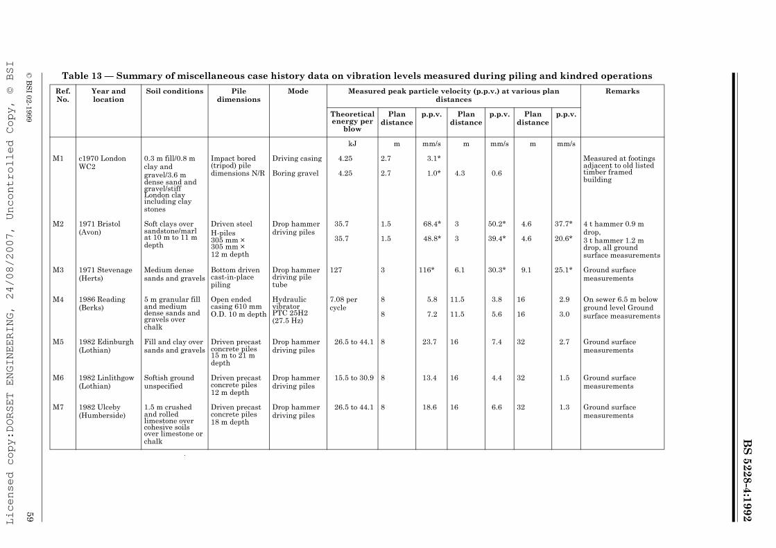
BS
5228-4:1992
© B
SI 02-1999
59
Table 13 — Summary of miscellaneous case history data on vibration levels measured during piling and kindred operations
Ref. No.
Year and location
Soil conditions Pile dimensions
Mode Measured peak particle velocity (p.p.v.) at various plan distances
Remarks
Theoretical energy per
blow
Plan distance
p.p.v. Plan distance
p.p.v. Plan distance
p.p.v.
kJ m mm/s m mm/s m mm/s
M1 c1970 London WC2
0.3 m fill/0.8 m clay andgravel/3.6 m dense sand and gravel/stiff London clay including clay stones
Impact bored (tripod) pile dimensions N/R
Driving casing 4.25 2.7 3.1* Measured at footings adjacent to old listed timber framed building
Boring gravel 4.25 2.7 1.0* 4.3 0.6
M2 1971 Bristol (Avon)
Soft clays over sandstone/marl at 10 m to 11 m depth
Driven steelH-piles 305 mm × 305 mm × 12 m depth
Drop hammer driving piles
35.7 1.5 68.4* 3 50.2* 4.6 37.7* 4 t hammer 0.9 m drop, 3 t hammer 1.2 m drop, all ground surface measurements
35.7 1.5 48.8* 3 39.4* 4.6 20.6*
M3 1971 Stevenage (Herts)
Medium dense sands and gravels
Bottom driven cast-in-place piling
Drop hammer driving pile tube
127 3 116* 6.1 30.3* 9.1 25.1* Ground surface measurements
M4 1986 Reading (Berks)
5 m granular fill and medium dense sands and gravels over chalk
Open ended casing 610 mm O.D. 10 m depth
Hydraulic vibrator PTC 25H2 (27.5 Hz)
7.08 per cycle
8 5.8 11.5 3.8 16 2.9 On sewer 6.5 m below ground level Ground surface measurements8 7.2 11.5 5.6 16 3.0
M5 1982 Edinburgh (Lothian)
Fill and clay over sands and gravels
Driven precast concrete piles 15 m to 21 m depth
Drop hammer driving piles
26.5 to 44.1 8 23.7 16 7.4 32 2.7 Ground surface measurements
M6 1982 Linlithgow (Lothian)
Softish ground unspecified
Driven precast concrete piles 12 m depth
Drop hammer driving piles
15.5 to 30.9 8 13.4 16 4.4 32 1.5 Ground surface measurements
M7 1982 Ulceby (Humberside)
1.5 m crushed and rolled limestone over cohesive soils over limestone or chalk
Driven precast concrete piles 18 m depth
Drop hammer driving piles
26.5 to 44.1 8 18.6 16 6.6 32 1.3 Ground surface measurements
Licensed copy:DORSET ENGINEERING, 24/08/2007, Uncontrolled Copy, © BSI
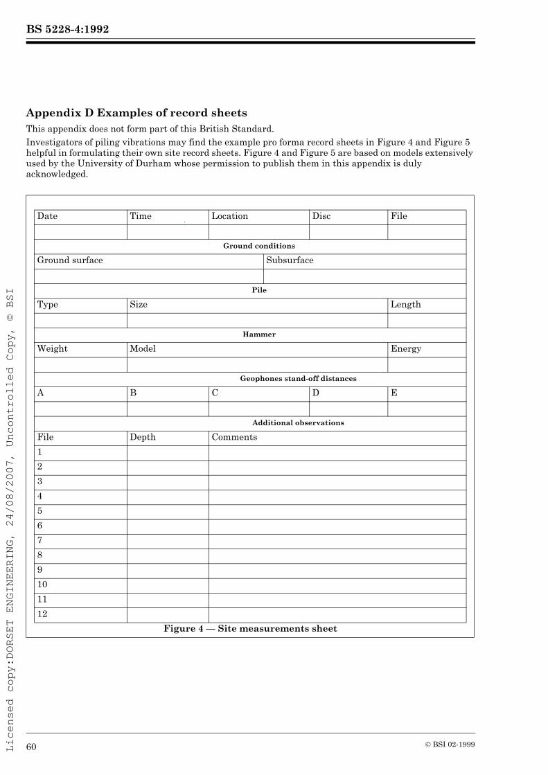
BS 5228-4:1992
60 © BSI 02-1999
Appendix D Examples of record sheetsThis appendix does not form part of this British Standard.Investigators of piling vibrations may find the example pro forma record sheets in Figure 4 and Figure 5 helpful in formulating their own site record sheets. Figure 4 and Figure 5 are based on models extensively used by the University of Durham whose permission to publish them in this appendix is duly acknowledged.
Date Time Location Disc File
Ground conditions
Ground surface Subsurface
Pile
Type Size Length
Hammer
Weight Model Energy
Geophones stand-off distances
A B C D E
Additional observations
File Depth Comments
1
2
3
4
5
6
7
8
9
10
11
12
Figure 4 — Site measurements sheet
Licensed copy:DORSET ENGINEERING, 24/08/2007, Uncontrolled Copy, © BSI

BS 5228-4:1992
© BSI 02-1999 61
Disc no Date File name
Pile
Type Sizes Length
Tubular steel. 740 mm diameter and 7 mm thickness 20 m
Hammer
Frequency Model Energy
27.5 Hz Vibrodriver 10.7 kJ/cycle
Peak particle velocity measurements mm.s–1
File no.
Depthm
Geophone-setStand-off
A2.8 m
B4.0 m
C8.0 m
D10.0 m
E15.0 m
H Radial 14.6 6.3 0.73 3.5 1.4
O Transverse 6.5 16.8 1.1 3.5 1.6
W 7.0 Vertical 12.2 13.1 2.1 3.6 1.5
8 Resultant 16.3 17.4 2.5 3.6 2.3
H Radial 6.5 9.8 1.7 2.6 1.1
O Transverse 6.4 14.0 1.3 3.0 2.0
W 9.0 Vertical 9.1 9.0 1.2 2.1 1.4
9 Resultant 11.3 17.4 2.1 3.6 2.3
H Radial 14.3 9.8 4.0 4.1 0.9
O Transverse 6.0 13.3 1.5 2.2 1.2
W 11.0 Vertical 10.2 10.9 4.9 5.0 1.9
10 Resultant 15.2 13.9 4.9 5.6 3.1
H Radial 12.2 11.5 3.1 6.2 2.2
O Transverse 13.8 18.7 2.6 5.1 1.6
W 12.5 Vertical 12.5 11.1 0.9 5.1 1.5
11 Resultant 18.6 21.9 3.2 7.1 2.5
H Radial 15.3 11.5 4.5 6.0 1.7
O Transverse 6.7 18.7 2.7 4.6 1.4
W 13.0 Vertical 15.5 13.2 5.2 3.3 1.6
12 Resultant 17.5 23.2 7.0 6.4 2.2
Figure 5 — Vibration data summary sheet
Licensed copy:DORSET ENGINEERING, 24/08/2007, Uncontrolled Copy, © BSI
BS 5228-4:1992
62 © BSI 02-1999
Appendix E BibliographyNOTE See also “Publications referred to”.
E.1 Publications relating to section 2Publications relating to section 2 include the items listed in Appendix E of BS 5228-1:1984 together with the following.INSTITUTION OF CIVIL ENGINEERS, Piling: Model procedures and specifications, London, 1978. Available from the Institution of Civil Engineers, Great George Street, Westminster, London, SW1P 3AA.FEDERATION OF PILING SPECIALISTS, Piling Specifications. Available from the Federation of Piling Specialists, Rutland House, 44 Masons Hill, Bromley, Kent BR2 9EQ.BS 8004 Code of practice for foundations.GILL, H.S., Control of impact pile driving noise and study of alternative techniques, Noise Control Engineering Journal, (March-April) 76-83, 1983. Available from the British Library, Boston Spa, N Yorks, or the British Library, Holborn, London.WYNNE, C.P., A Review of bearing pile types. CIRIA Report PG. 1, January 1977: reprinted 1988. Available from CIRIA, 6 Storey’s Gate, Westminster, London SW1P 3AU.E.2 Publications relating to section 3STEFFENS, R.J., Structural vibration and damage, Building Research Establishment Report, 1974. Department of the Environment, HMSO, London.WISS, J.F., Vibrations during construction operations Proceedings of the American Society of Civil Engineers, Journal of the Construction Division, 100 (CO3), 239-246, September 1974.CROCKETT, J.H.A., Piling vibrations and structural fatigue Proceedings of 1979 ICE Conference on recent developments in the design and construction of piles, 305-320. Thomas Telford, London, 1980.BOYLE, S., The effects of piling operations in the vicinity of computing systems, Ground Engineering, 23, (5), 23-27, 1990.RESEARCH REPORT No. 53. Ground vibration caused by civil engineering works, 1986. Available from the Transport and Road Research Laboratory, Old Wokingham Road, Crowthorne, Berkshire, RG11 6AU.BRE DIGEST 353, Damage to structures from ground-borne vibration, 1990. Available from the Building Research Establishment, Watford, Herts, WD2 7JR.
Licensed copy:DORSET ENGINEERING, 24/08/2007, Uncontrolled Copy, © BSI

BS 5228-4:1992
© BSI 02-1999
Publication(s) referred to
BS 5228, Noise control on construction and open sites. BS 5228-1, Code of practice for basic information and procedures for noise control. BS 6472, Guide to evaluation of human exposure to vibration in buildings (1 Hz to 80 Hz). BS 6841, Guide to measurement and evaluation of human exposure to whole-body mechanical vibration and repeated shock. BS 7385, Evaluation and measurement for vibration in buildings. BS 7385-1, Guide for measurement of vibration and evaluation of their effects on buildings. ATTEWELL, P.B., and FARMER, I.W., Attenuation of ground vibrations from pile driving, Ground Engineering, 6(4), 26-29, Thomas Telford, London, July 1973.WISS, J.F., Damage effects of pile driving vibrations, Highways Research Board USA No. 155, 14-20, Washington DC, 1967.GREENWOOD, D.A. and KIRSCH, K., Specialist ground treatment by vibratory and dynamic methods, Proceedings of the 1983 Institution of Civil Engineers International Conference on advances in piling and ground treatment for foundations, 17-45. Thomas Telford, London, 1984.WATTS, G.R., Case studies of the effects of traffic induced vibrations on heritage buildings. TRRL Research Report 156, 1988. Available from the Transport and Road Research Laboratory, Old Wokingham Road, Crowthorne, Berkshire RG11 6AU.MARTIN, D.J., Ground vibrations from impact pile driving during road construction. TRRL Supplementary Report 549, 1980. Available from the Transport and Road Research Laboratory, Old Wokingham Road, Crowthorne, Berkshire RG11 6AU.HEAD, J.M. and JARDINE, F.M., Ground-borne vibrations arising from piling. CIRIA Technical Note 142:1992. Available from the Construction Industry Research and Information Association, 6 Storey’s Gate, Westminster, London SW1P 3AV.
Licensed copy:DORSET ENGINEERING, 24/08/2007, Uncontrolled Copy, © BSI

BSI389 Chiswick High RoadLondonW4 4AL
|||||||||||||||||||||||||||||||||||||||||||||||||||||||||||||||||||||||||||||||||||||||||||||||||||||||||||||||||||||||||||||||
BSI Ð British Standards Institution
BSI is the independent national body responsible for preparing British Standards. Itpresents the UK view on standards in Europe and at the international level. It isincorporated by Royal Charter.
Revisions
British Standards are updated by amendment or revision. Users of British Standardsshould make sure that they possess the latest amendments or editions.
It is the constant aim of BSI to improve the quality of our products and services. Wewould be grateful if anyone finding an inaccuracy or ambiguity while using thisBritish Standard would inform the Secretary of the technical committee responsible,the identity of which can be found on the inside front cover. Tel: 020 8996 9000.Fax: 020 8996 7400.
BSI offers members an individual updating service called PLUS which ensures thatsubscribers automatically receive the latest editions of standards.
Buying standards
Orders for all BSI, international and foreign standards publications should beaddressed to Customer Services. Tel: 020 8996 9001. Fax: 020 8996 7001.
In response to orders for international standards, it is BSI policy to supply the BSIimplementation of those that have been published as British Standards, unlessotherwise requested.
Information on standards
BSI provides a wide range of information on national, European and internationalstandards through its Library and its Technical Help to Exporters Service. VariousBSI electronic information services are also available which give details on all itsproducts and services. Contact the Information Centre. Tel: 020 8996 7111.Fax: 020 8996 7048.
Subscribing members of BSI are kept up to date with standards developments andreceive substantial discounts on the purchase price of standards. For details ofthese and other benefits contact Membership Administration. Tel: 020 8996 7002.Fax: 020 8996 7001.
Copyright
Copyright subsists in all BSI publications. BSI also holds the copyright, in the UK, ofthe publications of the international standardization bodies. Except as permittedunder the Copyright, Designs and Patents Act 1988 no extract may be reproduced,stored in a retrieval system or transmitted in any form or by any means ± electronic,photocopying, recording or otherwise ± without prior written permission from BSI.
This does not preclude the free use, in the course of implementing the standard, ofnecessary details such as symbols, and size, type or grade designations. If thesedetails are to be used for any other purpose than implementation then the priorwritten permission of BSI must be obtained.
If permission is granted, the terms may include royalty payments or a licensingagreement. Details and advice can be obtained from the Copyright Manager.Tel: 020 8996 7070.
Licensed copy:DORSET ENGINEERING, 24/08/2007, Uncontrolled Copy, © BSI