non-destructive inverse determination of refractory wall material wear configurations in melting...
TRANSCRIPT

NON-DESTRUCTIVE INVERSE DETERMINATION OF REFRACTORY
WALL MATERIAL WEAR CONFIGURATIONS IN MELTING
FURNACESDANIEL P. BAKER
UPRIZER, Inc.; 1447 Cloverfield Blvd., Santa Monica, CA 90404, USA
GEORGE S. DULIKRAVICHUniversity of Texas at Arlington, Mechanical and Aerospace Eng. Dept., MAIDO Institute;
UTA Box 19018; Arlington, TX 76019, USA [email protected]
THOMAS J. MARTINPratt & Whitney Engine Company, Turbine Discipline Engineering & Optimization Group;
400 Main Street, M/S 169-20; East Hartford, CT 06108, USA
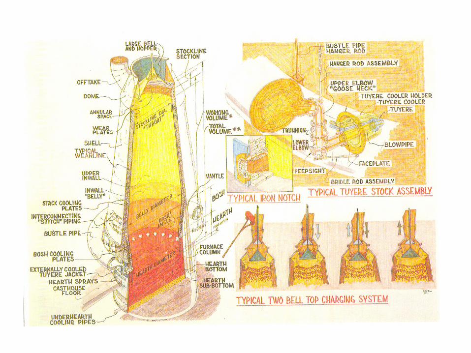

Gary Works No. 13 Blast Furnace Hearth Configuration, 1991

No. 13 Hearth Top ViewApparent TC Placement
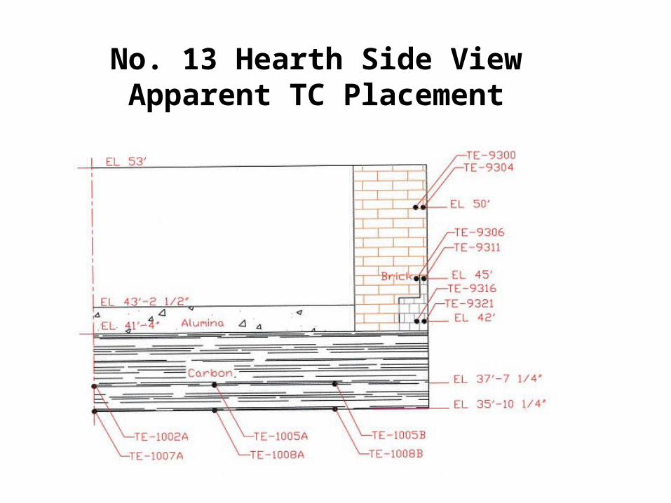
No. 13 Hearth Side ViewApparent TC Placement
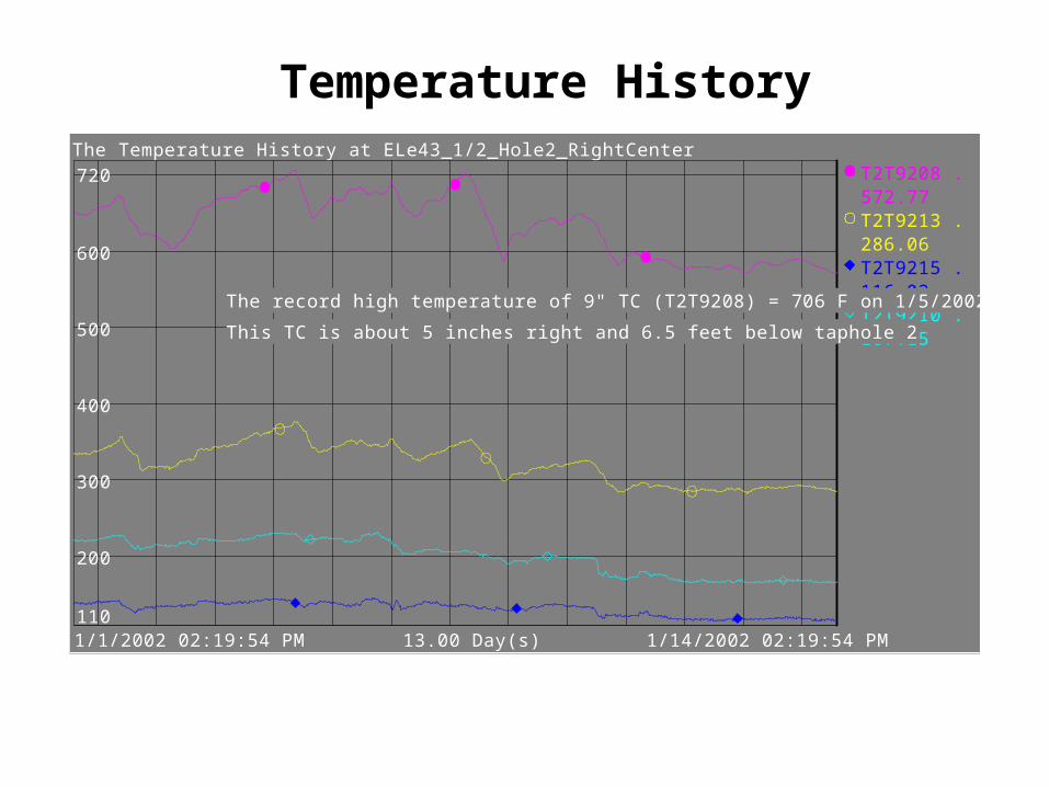
Temperature HistoryThe Temperature History at ELe43_1/2_Hole2_RightCenter
1/1/2002 02:19:54 PM 1/14/2002 02:19:54 PM13.00 Day(s)
T2T9208 .
T2T9213 .
T2T9215 .
T2T9210 .
200
300
400
500
600
110
720572.77
286.06
116.02
167.15
T2T9208 .
T2T9213 .
T2T9215 .
T2T9210 . The record high temperature of 9" TC (T2T9208) = 706 F on 1/5/2002
This TC is about 5 inches right and 6.5 feet below taphole 2
Introduction• Walls of the furnaces that contain molten material (metal, glass,
etc.) are made of layers of bricks of high-temperature resistive refractory material.
• High thermal gradients inside the melt create very strong circulation of the melt that causes erosion of the inner wall surface of the furnace.
• Thus, it would be highly desirable to continuously monitor the actual local thickness of the entire furnace wall so that the furnace can be shut down and the wall material repaired before the conditions for the burn-through accident can develop
• Determination of the thickness distribution of the refractory wall should utilize non-destructive measurement techniques and inverse shape determination concepts

Introduction• It appears that despite the separate efforts of several
independent research teams, reliable and affordable methodology for continuous sensing and monitoring of realistic three-dimensional variation of refractory wall thickness in smelters is still unavailable
• The objective of this presentation is to elaborate on an alternative method for predicting reliably and accurately realistic two-dimensional furnace wall wear configurations
• The approach employs the elastic membrane method, which first appeared as a concept for inverse design of aerodynamics shapes
• The shape determination method then uses the difference between the measured and the computed heat fluxes on the outer surface of the furnace as a forcing function in an elastic membrane concept for the determination of the inner (melt refractory) surface shape
• This approach can use any code for heat conduction (finite element, boundary element, etc.) without any modification

Thermal Boundary Conditions• Assume temperature and temperature gradient is available
on outer wall from sensors
• The inner shape is unknown, but assumed to have a known, constant temperature equal to the solidification temperature of the melt
• The assumption of isothermal solidus temperature on the unknown inner surface of the refractory wall is reasonable, but not exact because there could be layers of solidified melt and slug on some parts of this surface
• Assume thermal conductivity of the wall material is known

ELASTIC MEMBRANE CONCEPT FOR SHAPE EVOLUTION
Inverse determination of the inner surface of the refractory wall of a blast furnace is based on the use of measured and and on the postulated isothermal value of
oTodn
dT
iTThe outer surface shape is determined iteratively by solving the following:
o2
2
210 qds
nd
ds
ndn
computedmeasured
ooo dn
dT
dn
dTq
where the forcing function is:
n is shape corrections on outward normal vectors to the outer surface of the furnace wall.
Here, s is the outer wall contour-following coordinate
FOURIER SERIES SOLUTION OF SHAPE EVOLUTION EQUATION
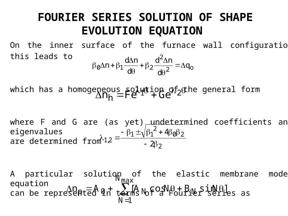
On the inner surface of the furnace wall configuration this leads to
which has a homogeneous solution of the general form
where F and G are (as yet) undetermined coefficients and eigenvalues are determined from
A particular solution of the elastic membrane model equation can be represented in terms of a Fourier series as
o2
2
210 qd
nd
d
ndn
21 GeFenh
2
202
112,1 2
4
maxN
1NNN0p ]NsinBNcosA[An
FOURIER SERIES SOLUTION OF SHAPE EVOLUTION EQUATION
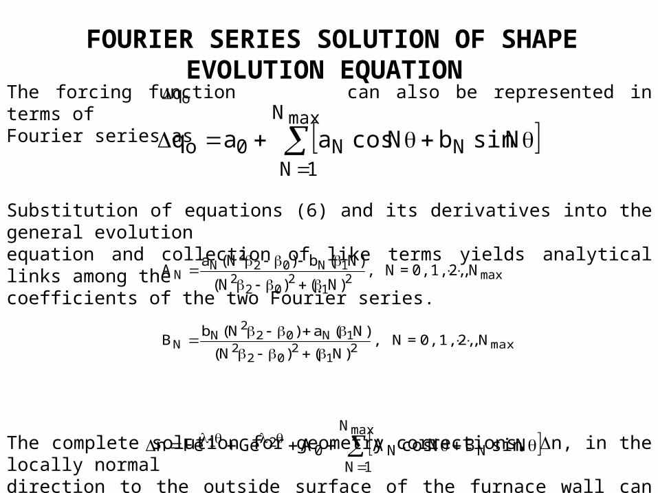
The forcing function can also be represented in terms of Fourier series as
Substitution of equations (6) and its derivatives into the general evolution equation and collection of like terms yields analytical links among the coefficients of the two Fourier series.
The complete solution for geometry corrections, n, in the locally normal direction to the outside surface of the furnace wall can be represented analytically as
oq
maxN
1NNN0o NsinbNcosaaq
max21
202
21N02
2N
N N,0,1,2,=N ,)N()N(
)N(b)N(aA
max21
202
21N02
2N
N N,0,1,2,=N ,)N()N(
)N(a)N(bB
max
21N
1NNN0 NsinBNcosAAGeFen

FOURIER SERIES SOLUTION OF SHAPE EVOLUTION EQUATION
•The unknown constants, F and G, are determined to be zero from the periodic closure conditions
• This elastic membrane model equation solution is better than the standard finite difference approach because any errors due to finite differencing are removed - because the formulation is exact
• The Fourier series formulation for the elastic membrane concept in inverse shape determination converges faster than the finite difference formulation
)2(n)0(n

NUMERICAL RESULTS • Tested for accuracy and speed of
convergence • Tested on horizontal and vertical
cross sections of an idealized furnace• Used two simple geometries with
outer surface radius Ro = 2.0 m • Assumed isotropic homogeneous
material • Each thermal analysis problem solved by 2-D BEM or by 2-D FEM

Test Case 1
• Oval doubly symmetric target inner boundary shape given as
• Thermal boundary conditions were Ti = 2000.0 K and To = 350.0 K
2i sin5.00.1R

Test Case 1
• Guessed inner shape was a unit circle
• =5000.0, =0.0 and = 0.0• Inner surface updated each iteration by
o 12
nRR oldi
newi

Test Case 1
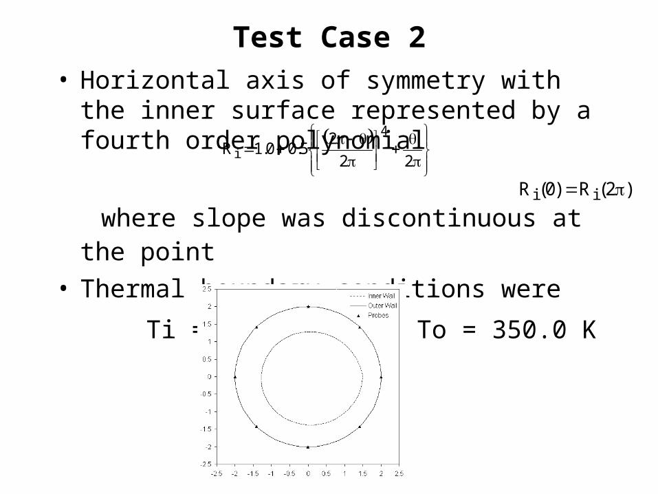
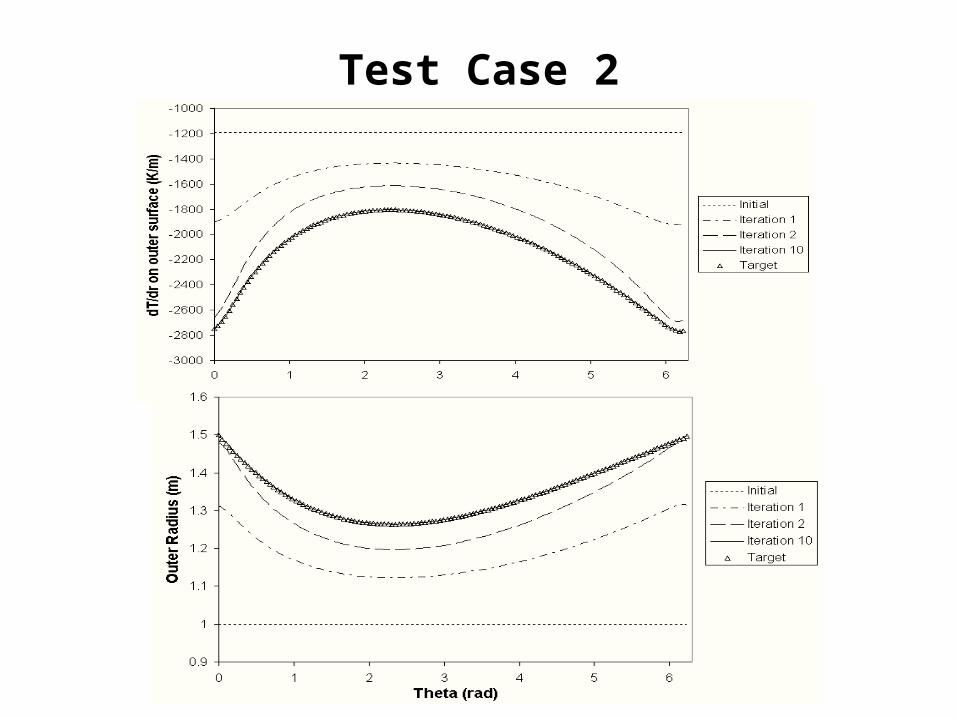
Test Case 2• Horizontal axis of symmetry with the
inner surface represented by a fourth order polynomial
where slope was discontinuous at the point
• Thermal boundary conditions were
Ti = 2000.0 K and To = 350.0 K
22
25.00.1R
4
i
)2(R)0(R ii
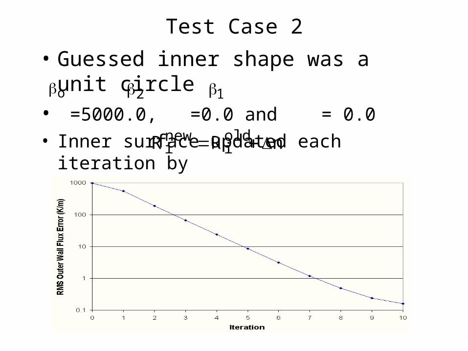
Test Case 2
• Guessed inner shape was a unit circle
• =5000.0, =0.0 and = 0.0• Inner surface updated each iteration by
o 12
nRR oldi
newi
Test Case 2

EFFECT OF MEASUREMENT
ERRORS • An actual furnace was not available to evaluate the
accuracy of this inverse shape determination method • Desirable to get maximum information out of as few
thermocouples as possible• We simulated measurement of the flux at only 8 points
on the outer surface of the furnace • Unbiased error was applied to those 8 measurements
by using a Gaussian probability distribution • Values of the randomly perturbed 8 flux values were
then spline fitted and interpolated to the remainder of the outer surface of the wall
• Random error was applied to the external temperature thus simulating actual field measurements with errors
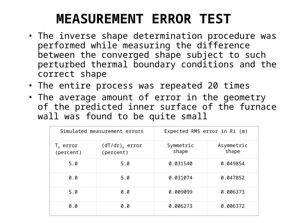
MEASUREMENT ERROR TEST • The inverse shape determination procedure was
performed while measuring the difference between the converged shape subject to such perturbed thermal boundary conditions and the correct shape
• The entire process was repeated 20 times• The average amount of error in the geometry of
the predicted inner surface of the furnace wall was found to be quite small
Simulated measurement errors Expected RMS error in Ri (m)
TO error (percent) (dT/dr)O error (percent) Symmetric shape Asymmetric shape
5.0 5.0 0.031540 0.049854
0.0 5.0 0.031074 0.047852
5.0 0.0 0.009099 0.006373
0.0 0.0 0.006273 0.006372

Initial guess and final shape for the eroded wall configuration, thermal field computed using FEM and non-
structured grid
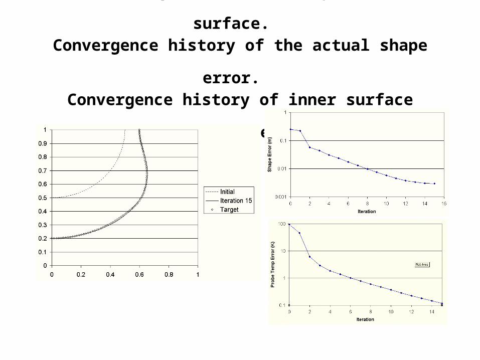
Initial, target and final shapes of inner surface. Convergence history of the actual shape error.
Convergence history of inner surface temperature error.
Summary• A conceptually new method has been developed and tested
for the automatic determination of wall thickness distribution in blast furnaces and smelters.
• The method accepts any available computer code capable of analyzing steady temperature field in the furnace wall.
• It requires a relatively small number of inexpensive thermocouples.
• The entire procedure is computationally very efficient and highly accurate even under the simulated conditions of measurement noise.
• There are plans to extend this method to realistic three-dimensional furnace wall configurations with sections having different temperature-dependent thermal properties.