non-rotating stabilizer for earth boring and bearing therefor
TRANSCRIPT
United States Patent [191 Olson
[11] 4,083,612 [45]
[54] NON-ROTATING STABILIZER FOR EARTH BORING AND BEARING THEREFOR
Wallace Fred Olson, Midland, Tex.
Smith International, Inc., Midland, Tex.
Appl. No.: 732,608 Filed: Oct. 15, 1976
Int. Cl.2 ...................... .. F16C 17/00; F16C 17/08 US. Cl. .................................. .. 308/4 A; 166/241;
308/135; 308/238; 308/239 ?eld of Search ............... .. 308/4 R, 4 A, 8.2, 37,
308/ 134.1, 135, 139 R, 160, DIG. 7, DIG. 8, 238, 158, 163, 239; 166/241; 175/76, 325, 406,
408
[75] [73]
Inventor:
Assignee:
[21] [22] [51] [52]
[58]
[56] References Cited U.S. PATENT DOCUMENTS
8/ 1941 Caldwell ......................... .. 308/134.l
3/1942 Yeomans .... .. 308/160
12/1954 Robishaw .. 308/4 A 4/1969 James . . . . . . . . . . . . . .. 308/238
3,774,983 1l/l973 Lagally .... .. 308/DIG. 8 3,932,004 l/l976 Orndorff ...................... .. 308/DIG. 8
Primary Examiner—Trygve M. Blix Assistant Examiner-Charles E. Frankfort Attorney, Agent, or Firm-Murray Robinson; Ned L. Conley; David Alan Rose
[57] ABSTRACT A stabilizer for a big hole drill stem includes a journal, i.e., a sleeve, adapted to be slipped over the stem. The
2,253,416 2,274,764 2,696,367 3,436,129
sleeve has an apertured lower ?ange to seat on the stem stool and receive the pins thereof to prevent relative rotation of sleeve and stem. The upper end of the sleeve has a clutch jaw for interlocking with the clutch jaw on the lower end of a canister weight forming part of a drill string assembly. Also, the upper end of the sleeve, just below the clutch, has a split clamp held in frictional engagement with the sleeve in an annular groove there about. Just below the clamp there is an annular upper ?ange having stop lugs engageable between the ears of the clamp to prevent relative rotation. Rotatably mounted on the sleeve between the upper and lower ?anges is a fixed blade stabilizer body. A marine bearing is provided at the inner periphery of the stabilizer to take radial loads. The marine bearing is fabricated from a plurality of ?uted rubber rings cemented to each other and to the steel part of the body. Between each end of the body and the ?anges is a thrust bearing. Each thrust bearing is a sandwich comprising two thrust plates, one screwed to the body and one screwed to the adjacent ?ange, with a support plate studded with thrust buttons ?oating therebetween. The buttons have heads and extend through holes in the retainer plate with the heads alternately on opposite side of the retainer plate. Prefer ably the thrust buttons are made of a long wearing, hard, high strength plastic, compatible with salt water, drilling mud, sand, and rock cuttings, a suitable plastic being one sold under the tradename “Ultra-Cladd” or “Ultra-Wear”, same being an ultra high molecular weight polyethylene.
23 Claims, 16 Drawing Figures
Apr. 11, 1978’


US. Patent April 11, 1978 Sheet2 of8 4,083,612
\ ' \
j ' \w 43 5/5550 W/M \ _‘ / \
any. SAND /\ / ‘i
\ ' / -\

US. Patent April 11, 1978 Sheet3 of8 4,083,612
//7
/02?
/59
£7
7/
US. Patent April 11, 1978 Sheet4 of8 4,083,612

US. Patent VApril11,1978 Sheet5of8 4,083,612

U.S. Patent April 11, 1978 Sheet6 of8 4,083,612
/43
/39

US. Patent April 11, 1978 Sheet7 of8 4,083,612

US. Patent April 11, 1978 Sheet8 of8 4,083,612
/7.7
/57 J
/75
5
w y
. m
/0 I 3 / A
+0_. 5
H . . . 4“ ,
. 7\ H
n'lllll I
4 ‘TI IR / SQMQSQ yr QQH QQQN

4,083,612 1
NON-ROTATING STABILIZER FOR EARTH BORING AND BEARING THEREFOR
BACKGROUND OF THE INVENTION
This invention pertains to earth boring tools and more particularly to a ?xed blade non-rotating stabilizer especially adapted for drilling large diameter blind holes, e.g., over 30 inches in diameter.
In big hole drilling the tubular drill stem usually is provided at its lower end with a stool to the bottom of which is bolted a drilling cutter assembly or drill bit. An assembly of tools such as stabilizers and weights are spindled on the drill stem, the lower end of the assembly being supported by the stool. Usually the tool assembly merely rests in frictional engagement with the stool although in some cases the stem has been provided with a clutch jaw ?xed thereon and engageable with a clutch jaw in the stabilizer skirt to positively prevent relative rotation of the stabilizer sleeve on the drill stem. Some times the stabilizer has been formed integral with the stool itself. Sometimes the stem is omitted and the tools are provided with ?anges which bolt together to form an assembly to transmit torque to the drill bit or cutter assembly.
Fixed blade non-rotating stabilizers are well known for use both in small diameter holes such as oil wells and blast holes and in big holes. Various forms of anti-fric tion bearings have been used, at least with smaller size stabilizers. See for example the copending United States patent applications of applicant’s assignee, Ser. Nos. 720,695; 720,954; 721,089; 721,090 ?led Sept. 7, 1976. In connection with big hole stabilizers, marine bearings for radial loads have been used. Also steel thrust plates with bronze thrust bodies held to one side thereof by cap screws have been employed, the thrust plates being fastened to the rotating part of the stabilizer.
Difficulty has been experienced with the thrust bear ings for big hole stabilizers because of the heavy weight involved. For example the non-rotating body of the stabilizer may weigh over a ton.
Roller stabilizers for big hole drilling are disclosed in US. Fat. to applicant’s assignee Nos. 3,302,983 and 3,413,045, which disclose the use of marine bearings and of roller thrust bearings for the stabilizer rollers. Also, the latter patent shows the use of pinned and apertured ?anges for making ?anged connections between a big hole stabilizer and a drill bit and drill collar. However these patents are not concerned with bearings for non rotating stabilizers, nor the stacking of big hole tools about a drill stem, nor the provision of means to insure that relative rotation occurs at the bearings between the non-rotating stabilizer body and its journal or inner sleeve rather than between the sleeve and the drill stem.
SUMMARY OF THE INVENTION
According to the invention an assembly of big hole tools, i.e. non-rotating stabilizers and weight canisters, each having an internal sleeve providing a passage therethrough, are spindled on a drill stem with their weight resting on a stool connected to the lower end of the drill stem. The sleeves of the tools in the assembly are interlocked to each other to prevent relative rota tion. The sleeve of the lowermost tool of the assembly is interlocked with the stool to prevent relative rotation. A split clamp disposed in an annular groove in the drill stem engages the sleeve of the uppermost tool of the assembly thereby holding the assembly down on the
10
20
25
35
40
45
50
55
60
65
2 stool and preventing relative axial movement of the assembly and drill stem. Each non-rotating stabilizer in the tool assembly
comprises a journal formed by a sleeve, with a ?xed annular ?ange welded to the lower end of the sleeve and a loose annular ?ange disposed near the upper end of the sleeve. The lower ?ange is provided with a ring of sockets receiving upstanding pins on the stool to interlock the ?xed ?ange and sleeve to the stool. A split clamp frictionally engaging an annular groove around the upper end of the sleeve keeps the loose ?ange from coming off the top of the sleeve. Also, lugs on the loose ?ange engage between the ears of the clamp to prevent relative rotation. A clutch jaw at the extreme upper end of the sleeve engages a correlative jaw on the lower end of a weight canister sleeve. The upper end of the weight canister sleeve is provided with a pinned ?ange to re ceive another stabilizer sleeve. Around each stabilizer sleeve, between the ?xed and
free ?anges, is disposed a fabricated, ?xed blade, stabi lizer body. At its inner periphery the stabilizer body has a marine radial bearing within which rotates the stabi lizer sleeve. The radial bearing comprises a stack of a plurality of internally ?uted rubber rings cemented one to the other and to the adjacent steel of the fabricated body. Between each end of the stabilizer body and the adja
cent ?xed or loose ?ange is a thrust bearing. Each thrust bearing includes a pair of annular thrust plates, one plate being connected to the adjacent end of the stabi lizer body by a ring of screws and the other being con nected to the adjacent ?ange by a ring of screws. Be tween each pair of thrust plates is disposed an annular support or retainer plate. The retainer plate has a ring of holes therethrough. Thrust buttons extend through the holes to engage the thrust plates. The buttons have heads and the buttons are disposed with their heads alternately on one and the other side of the retainer plate. The buttons are made of hard, high strength, wear resistant, low friction material adapted for long life in the expected environment of salt water, drilling mud, cuttings and sand. Preferably the buttons are made of a plastic known to the trade as “ULTRA-CLADD” or “ULTRA-WEAR”. This product is available from Indian Industries, Arlington, Texas, and is an ultra high molecular weight polyethylene. The drill string including the stabilizer in accordance
with the invention is intended for use in rotary drilling in which the drill string is rotated to turn a bit against the bottom of the hole, and drilling ?uid is pumped down the drill string, out around the bit to pick up the cuttings, and back up the hole in the annulus around the exterior of the drill string. Or in reverse circulation the ?uid is pumped down the annulus and back up inside the drill string. In either case drilling ?uid in the annulus must move through or past the stabilizer. Some of the fluid will ?ow between the blades on the outer periph ery of the stabilizer body. Some of the ?uid will ?ow through vent holes in the end plates of the fabricated body and then through the hollow body, the vent holes also preventing the body from trapping air and provid ing bouyancy. The remainder of the drilling ?uid will ?ow radially through the thrust bearings and axially through the radial bearing providing lubrication for them all. With this material and construction, the thrust bear
ings have a longer life than was obtained with the prior art friction bearings discussed above. Also, the con

4,083,612 3
struction of the thrust bearings adapts them to easy replacement if they do wear out. The interlock of the sleeves with the drill stem insures that rotation takes place at the bearings rather than between the sleeves and mandrel. This prevents wear between the stabilizer sleeve flanges and the ?anges on the canisters and the drill stem stool and between the sleeve and stem. Other advantages and objects of the invention will appear from the following description of a preferred embodi ment thereof, reference being had to the accompanying drawings. BRIEF DESCRIPTION OF THE DRAWINGS
The drawings are to scale. For reference, the well bore has a diameter of four feet. FIGS. 1A and 1B, together hereinafter referred to as
FIG. 1, form an elevation showing the lower portion of a well bore in which is disposed the lower part of a drill string including a drill bit, drill stem with stool, and assembly of tools on the stem including weight canisters and stabilizers in accordance with the invention; FIG. 2 to a larger scale than FIG. 1, is a bottom view
of the drill stern stool shown in FIG. 1; FIGS. 3A and 3B, together hereinafter referred to as
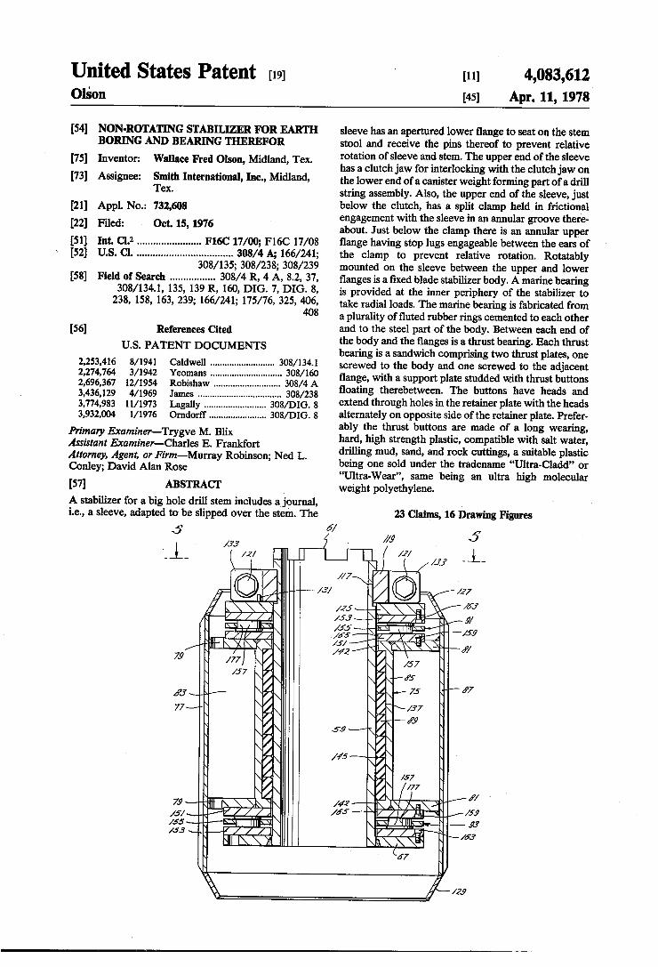
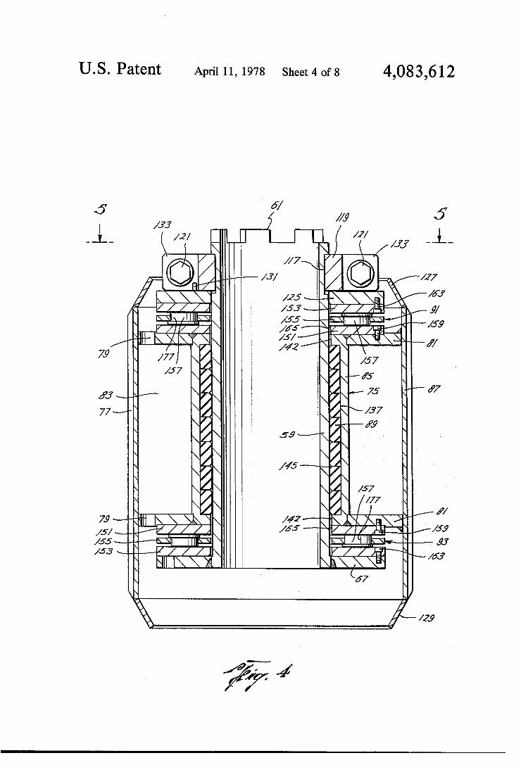
FIG. 3, form an axial section to the same scale as FIG. 2 showing one of the stabilizers and the weight canister thereabove, both mounted on the drill stem and its stool; FIG. 4 is a view similar to FIG. 3A but showing only
the stabilizer without the drill stem and weight canister; FIG. 5 is a top view of the stabilizer shown in FIG. 4; FIG. 6 is the top view of one of the body plates of the
stabilizer; FIG. 7 is an axial section through one of the bearing
rings of the stabilizer’s radial bearing; FIG. 8 is a top view of the ring shown in FIG. 7; FIG. 9 is a fragmentary top view of one of the thrust
button support rings of the stabilizer’s thrust bearings; FIG. 10 is a side view of the ring portion shown in
FIG. 9; FIG. 11 is a fragmentary top view of one of the thrust
plates of the stabilizer’s thrust bearing; FIG. 12 is a side view of the ring portion shown in
FIG. 11; FIG. 13 is an end view of one of the thrust buttons;
and FIG. 14 is a side view of the button shown in FIG. 13.
DESCRIPTION OF THE PREFERRED EMBODIMENT
Tool Assembly and Details of Canister
Referring now to FIG. 1 there is shown an earth bore 21. This is a typical “big hole”, having a diameter of four feet. Within the earth bore is the lower portion of a rotary drilling string comprising a tubular drill stem 23. At the upper end of the stem is a threaded box 25 for making connection with the next above component of the drill string, e.g., a length of drill pipe. At the lower end of the drill stem there is a ?ange 27 welded to the stem. A drill bit or drilling roller cutter assembly 29 is secured to the ?ange by a ring of bolts (not shown). The assembly 29 includes a plurality of rotatably mounted toothed cones 31. On top of ?ange 27 is welded a ,wheel 33 (see also
FIG. 3B). On top of wheel 33 is welded ?ange 35. To gether ?anges 27 and 35 and wheel 33 form a stool 37.
Resting with their weight on stool 37 is an assembly 39, of annular drilling tools, each having an internal
15
20
25
35
45
50
55
4 sleeve spindled on drill stem 23. The assembly includes stabilizer 41, weight canister 43, stabilizer 45, weight canister 47 and stabilizer 49. A split hold-down clamp 51 frictionally engages an annular groove in and around the drill stem 23 justabove stabilizer 49. A ring 50 welded to guard cone 52 is disposed between clamp 51 and stabilizer 49. Cone 52 acts as a guide to facilitate removal of the drill stern and tool assembly from the earth bore. The tool assembly is held against axial mo tion relative to stem 23 by clamp 51 and stool 37. The tool sleeves are held against rotation relative to each other and relative to drill stem 23 by means next to be described. At the bottom of each weight canister sleeve 53 (see
also FIG. 3B) is one jaw 55 of a jaw clutch 57. At the top of the tubular journal or sleeve 59 of each stabilizer ' is the other jaw 61 of the clutch 57. The clutches 57 ' prevent relative rotation of the stabilizers and weight canisters thereabove.
Referring now more particularly to FIG. 3B, but also to FIG. 1, the top ?ange 35 to stool 37 is provided with a plurality of upstanding pins 63 which engage sockets or holes 65 in ?ange 67 welded to the lower end of stabilizer sleeve 59. Other means, hereinafter described, prevent relative rotation of each stabilizer and the stool or canister therebelow. As best shown in FIGS. 3A and 3B, each canister
includes a plurality of tube sections welded together to form a drum 70. The drum is concentric with canister sleeve 53, being positioned thereabout by a plurality of bulkheads 72, 74, 76 welded to the drum and sleeve. The inner bulkheads 74 are provided with a plurality ‘of holes 80 which interconnect the interior space 82 of the canister so that it can be easily ?lled with high density material such as sand, lead shot, cement, or other high density material. This material is inserted by cutting a hole in the drum and pouring the material in and then closing the hole. The end bulkheads 72, 76 are welded to Gussett plates 84, 86 for added support. Welded to the upper end of canister sleeve 53 and
gasket plates 84 is a ?ange 69, which is provided with a plurality of upstanding pins 77. The pins 77 are received in the holes 65 in ?ange 67 on the sleeve of the stabilizer thereabove. The apertured stabilizer ?anges 67 on the one hand and the pin studded canister ?anges 69 and stool ?ange 35 on the other, provide clutch means which prevent relative rotation of the stabilizers and the ' stool or canisters therebelow. Anchoring of tool assembly 39 to drill stem 23 in the
manner just described prevents relative axial and rota tional motion of the drill stem and tool sleeves, thereby eliminating wear that would be caused by such motion.
OPERATION
In operation, the drill string is rotated in the earth bore, e.g., by surface means such as a rotary table or power swivel, thereby rotating the cutter assembly or drill bit 29 against the end of the bore. Fluid is pumped down the drill pipe and drill stem and out through open ings in the cutter assembly and ?ows back up the annu lus between the earth bore wall and the drill string, carrying the cuttings to the surface. If the earth bore is in the ocean ?oor, conductor pipe may be used to ex tend the annulus through the water to the top surface. The weight canisters, bear down on the cutter assembly through stool 37, thereby urging the cutters 31 into the bottom of the bore. The drill stem and stabilizer sleeves,

4,083,612 5
interlocked against rotary rotation as described above, rotate within the outer bodies 75 (FIG. 3B) of the stabi lizers 41, 45, 49. Ribs 77 on the outer peripheries of the bodies 75 centralize the stabilizer bodies in the earth bore and the bodies in turn centralize their sleeves and the drill stem in the bore. This causes the drilling cutter assembly to tend to drill a straight bore.
FLUID PATHS
During drilling, drilling ?uid passes up outside the bodies 75 of the stabilizer between blades 77. Fluid also ?ows upwardly inside the stabilizers through openings 79 (FIGS. 4 and 6) in the end plates 81 thereof and through the interior space 83 between the concentric inner and outer shells 85, 87 welded to the end plates to form the stabilizer body. Fluid also ?ows between the inner sleeve 59 and the outer body 75 of each stabilizer, travelling through the radial bearings 89 and the upper and lower thrust bearings 91, 93 by means of which the sleeve 59 is rotatably mounted within the stabilizer body. The latter ?uid ?ow lubricates and cools the bearings, but because of its nature is also injurious to the bearings, since the usual ?uid will be a mixture of salt water, drilling mud, sand and cuttings. For this reason bearings of special construction are provided in accor dance with the invention.
DRILL STEM AND STOOL
The drill stem 23 on which the tool assembly 39 is disposed is shown in FIGS. 1, 2 and 3, and the stool 37, at the lower end thereof is best shown in FIG. 3B. The “wheel” 33, welded to the bottom ?ange 27 of the stool 37, comprises a rim 95, a hub 97, and a plurality of spokes or radial plates 99. The spokes are welded to the hub and rim. The hub ?ts closely around drill stem 23 to give lateral support to the stool. The bottom ?ange 27 of the stool is best shown in
FIG. 2. It is provided with sockets or holes 101 to re ceive upstanding pins (not shown) on top ?ange 103 (FIG. 1) of the drill bit or cutter assembly 29, the pins being similar to pins 71 (FIG. 3B) on top of canister ?ange 69. In addition, bottom ?ange 27 of the stool is provided with a ring of holes 107 to receive bolts (not shown) which pass through like holes in top ?ange 103 of the drill bit assembly and hold the ?anges together. As shown in FIG. 1B, the upper end of the drill stem
is reduced wall thickness forming a neck 109 of the same size as drill pipe to be connected thereto by box 25. Box 25 can be screwed onto neck 109 or welded thereto or formed integrally therewith.
Just below neck 109 there is an annular groove around the drill stem. It is in this groove that split clamp 51 is disposed. The two halves of clamp 51 are held together and in tight frictional engagement with the bottom of groove 111 so as to prevent the clamp from coming out of the groove or rotating therein about the drill stem. Bolts and nuts 113, 115 hold the two halves of the clamp together in that manner.
STABILIZER ASSEMBLY
Referring now to FIGS. 1, 3B and more particularly to FIGS. 4 and 5, each stabilizer includes inner sleeve or journal 59 which is rotatably mounted within body 75. Welded to the lower end of sleeve 59 is ?xed ?ange 67. There is an annular groove 117 around the upper part of sleeve 59. A split clamp 119, similar to split clamp 51, is held in tight frictional, nonrotatable engagement with sleeve 59 within groove 117 by means of bolts and nuts
20
25
30
35
45
50
55
65
6 121, 123. An annular ?ange 125 is disposed around sleeve 59 and is restricted against upward movement by hold down clamp 119. As shown in FIG. 5, stop lugs 131 welded to the top of ?ange 125 limit relative rota tion of the ?ange and sleeve 59, being positioned to engage the apertured ears 133 on the clamp through which pass the bolts 121.
Thrust bearings 91, 93, support the stabilizer body 75 between ?xed ?ange 67 and loose ?ange 125. The thrust bearings bear against the end plates 81, 83 of the stabi lizer body. The inner shell 85 of the stabilizer body is disposed around sleeve 59 and rotatably mounted thereon by radial bearing 89. The outer shell 87 of the stabilizer body is welded to the end plates 81 and carries the ribs or blades 77. Conical guards 127, 129 on the upper and lower ends of outer shell 87 protect the thrust bearings 91, 93 when the stabilizer is moved axially in the earth bore and help guide the stabilizer past inward protrusions in the bore.
RADIAL BEARING
The end plates 81 of the stabilizer body project radi ally inwardly beyond inner shell 85 forming therewith an annular pocket 137. Within this pocket is disposed a stack of elastomer rings forming radial bearing 89. The rings 139, one of which is shown in FIGS. 7 and 8, are internally ?uted at 141. The ?utes extend parallel to the ring axis. The ?utes of the several rings making up the stack are aligned so as to form continuous ?uid passages extending the length of the stack. These passages con nect with the annular ?uid passages 142 formed be tween the inner peripheries of ?anges 81 and sleeve 59 when the sleeve is journaled within the stack of rings forming the radial bearing 89. The rings have rabbets at their inner peripheries as
shown at 143. Adjacent rabbets form circumferential grooves 145 on the inside of the stack (FIG. 4) which interconnect the longitudinal ?uid passages provided by ?utes 141. The rings are cemented together and the resulting stack is cemented to the steel pocket 137. Pref erably the elastomer of the rings 139 is a natural or synthetic rubber such as a nitrile that is oil and sea water resistant and has a Shore A scale durometer hardness between 60 and 90, e.g. 70.
THRUST BEARINGS
Referring now to FIGS. 3B, 4 and 9 through 14, each of the thrust bearings 91, 93 comprises a pair of rings or ' annular inner and outer ?anges or thrust plates 151, 153 between which is sandwiched an annular support ring 155 carrying a plurality of thrust bodies or buttons 157. The inner thrust plates 151 are secured to the end
plates of the stabilizer body by screws 159, disposed in countersink holes 161 (FIGS. 11, 12). In like manner, the outer thrust plates 153 are secured to the ?anges 67 and 125 by screws 163 disposed in similar countersink holes in the outer thrust plates. The thrust plates are made of steel, preferably a hard, corrosion resistant material, ground ?at and smooth on the inner surfaces which engage thrust buttons 157. The plates 151, 153 are interchangeable so that either may be an inner plate or an outer plate. To this end the inner diameters of the thrust plates are larger than the outer diameter of sleeve 59 so that there will be ample ?uid passage 165 formed between the sleeve and inner plate for ?uid ?owing through the thrust bearing. Fluid passages 165 commu nicate with ?uid passages 142 and the longitudinally

4,083,612 7
extending passages formed by ?utes 141 inside the ra dial bearing.
Support rings 155 (FIGS. 9 and 10) are provided with a plurality of annularly disposed circumferentially spaced cylindrical holes 167 positioned radially midway between their inner and outer peripheries 169, 171. Rings 155 are preferably made of hard corrosion resis tant steel similar to that of thrust plates 151, 153. Both sides of rings 155 are ground ?at and smooth. Rings 155 provide strength and close ?tting surfaces to support thrust buttons 157 and retain them in proper position.
Thrust buttons 157 (FIGS. 13 and 14) have generally cylindrical bodies 173 adapted to extend through holes 167 in the retainer ring and ?t closely therein. The buttons have enlarged portions at one end, e.g. cylindri cal heads 175. The buttons are assembled in ring 155 with alternate buttons having their heads on opposite sides of the ring. When sandwiched between thrust plates 151, 153, the buttons cannot move axially. The ring is held by the button heads midway between and out of contact with the plates. The heads and the protu berant tips 177 (FIG. 4) have smooth ?at surfaces 179, 181 adapted to engage the ground surfaces of the thrust plates. The shoulder 183 between the heads and bodies of the buttons are smooth ?at surfaces to engage fully with the ground surfaces of the ring 155. The diameters of heads 175 are small enough so that
the heads and tips are spaced apart circumferentially leaving ?uid passages 185 therebetween (FIG. 9) which communicate at their inner ends with ?uid passages 165 at the inner thrust plates 165 (FIG. 4) and at their outer ends with the ?uid passages 187 (FIG. 3B) between the outer shell 87 of the stabilizer body and the ?anges 125 and 67 on the stabilizer journal sleeve. Fluid can thus ?ow through the stabilizer radial and thrust bearings, entering and leaving through the inner peripheries of conical guides 127, 129 at the ends of shell 87. The thrust bearings can easily be replaced whenever
they wear out. The thrust buttons can be pushed out of their support ring and new ones substituted. The sup port rings can be reground or replaced. The thrust plates can be unscrewed from the adjacent ?anges and end plates and reground or replaced. However, the construction is such as to maximize the life of the thrust bearings. The drilling ?uid ?owing between the buttons cools and lubricates the bearings and washes them clean. The material preferred for the thrust buttons has a long life.
It is contemplated that the subject drilling assembly and stabilizer may be used in connection with the dril ling of holes for foundation piers in the bottom of the ocean ?oor. Here the environment is a highly saline water contaminated with sand, mud, and drilling cut tings. A material for the thrust buttons that has been discovered to be well suited for this environment is a plastic material sold under the tradename “ULTRA CLADD” or ULTRA-WEAR”. This material is an ultra high molecular weight polyethylene. The pub lished physical data sheet for this material lists the fol lowing properties:
density .94 grams per cubic centimeter
hardness Rockwell R-64 - tensile strength 6400 psi elongation 400% de?ection temperature 84 degrees C. at 66 psi melting point 130-136 degrees C.
20
25
35
40
65
8 -continued
coefficient of ther- (7.2) (10-5) ilL/ilL/deg. F mal expansion tensile impact 1030 ft.-lb. per sq. in. impact stops at 25 feet at 45 calibre
Or 357 magnum calibre bullet IZOD impact did not break between 23 deg. C
and — 140 deg. C. 4000 F. (50) hours
~300 deg. F. to 180 deg. F.
environmental stess crack useable temperature range water absorption over 24 hours
0.01 percent
From “Polymers and Resins” by Brace Golding, copywright 1959, it appears that polyethylene may be made by three general categories of processes, as fol lows:
Range of Molecular Density
Process Weight Range (a) high pressure-low density 5000 to 40000 .91 to .92 (b) high pressure-high density — to 50000 .935 to .94 (c) low pressure-high density 10000 to 2000000 .93 to .960
The product of the processes (b) and (c) is said to be similar. If the densities are plotted against molecular weight on semilog graph paper, lines through the range terminal points given above for each process have simi lar slopes and a single line may be used for processes (b) and (c). From this it appears that the molecular weight of “ULTRA-CLADD” or “ULTRA-WEAR” is about 50000. An ultra high molecular weight polyethylene may be said to be one having a molecular weight in excess of 40000, the top of the range for process (a). “ULTRA-CLADD” or “ULTRA-WEAR” data
sheet further discloses it as non-toxic, odorless, tasteless and self-lubricating, to have a low coef?cient of thermal expansion, and to be easily machinable, and abrasion resistant. With this and the previously mentioned prop erties, it constitutes an eminently suitable material for the thrust buttons. While a preferred embodiment of the invention has
been shown and described, many modi?cations thereof can be made by one skilled in the art without departing from the spirit of the invention.
I claim: 1. A stabilizer comprising a body including wall contacting means adapted to
contact the side wall of an earth bore to centralize a drill stern rotatable in such bore,
said body having an axial opening therethrough pro viding a radial bearing and adjacent each end hav ing a portion adapted to take thrust, sometimes hereinafter referred to as a thrust portion,
journal means rotatably mounted in the radial bearing and having a radial ?ange at each end, each ?ange being ?xed against axial movement away from the other ?ange,
thrust bearing means between each journal ?ange and the adjacent thrust portion of the body,
each thrust bearing means comprising a ?oating sup port ring and anti-friction means carried by the ring and protruding therefrom in the direction that ex tends between the journal ?ange and the thrust portion of the body, said ring and said anti-friction means separating said ?ange and said thrust portion by a distance greater than the thickness of the ring,

4,083,612 at least the portion of said anti-friction means that protrudes from said ring transmitting thrust,
?uid transmission means to transmit ?uid between parts of the earth bore separated by the stabilizer body,
said ?uid transmission means including outer ?uid passage means between said wall contacting means and inner ?uid passage means through the stabilizer providing space for ?uid passage between the ra dial bearing and journal and space for ?uid passage across each thrust bearing connecting with the ends of the ?rst said space.
2. Stabilizer according to claim 1, said anti-friction means protruding from both sides of
each ring to keep the ring out of contact with sur faces rotating relative thereto.
3. Stabilizer according to claim 2, said anti-friction means extending through holes in
the rings and including means limiting movement of the anti-friction means through said holes.
4. Stabilizer according to claim 3, said anti-friction means having portions of uniform
cross-section adapted for insertion through said holes, said limiting means being heads on said anti friction means too large to pass through said holes, adjacent anti-friction means being disposed with their heads on opposite sides of the rings.
5. Stabilizer according to claim 4, said anti-friction means being made of plastics mate
rial and said thrust portions of the stabilizer body and said journal ?anges each being provided with a steel thrust surface engaging said anti-friction means.
6. Stabilizer according to claim 5, said metal being steel and said plastics material being
polyethylene. 7. Stabilizer according to claim 6, said polyethylene having an ultra high molecular
weight characterized by a density of 0.94 grams per cubic centimeter.
8. Stabilizer according to claim 7, , said polyethylene being further characterized as fol
lows:
hardness melting point coef?cient of thermal
Rockwell R-64 130-136 deg. c (7.2) (10's) in./in./deg. F
expansion elongation 400 percent tensile strength 6400 psi
9. Stabilizer according to claim 6, said thrust surfaces being provided by thrust rings
releasably secured to said thrust portions of the stabilizer body and to said journal ?anges, said support rings and anti-friction means being sand wiched between said thrust rings.
10. Stabilizer according to claim 9, said body comprising inner and outer steel shells
forming an annular space therebetween and end plates over the ends of said annular space con nected to said shells, said end plates being disposed axially inwardly of said thrust bearings.
11. Stabilizer according to claim 10, said radial bearing including a plurality of internally
?uted elastomer rings cemented together coaxially to form a stack with the ?utes of the rings being aligned so as to form ?uid passages extending the length of the stack on the inner periphery thereof,
15
25
35
45
55
65
10 the outer periphery of said stack being cemented to said inner shell, . I
said ?uid transmision means including fluid passages through said end plates communicating with said ?utes.
12. Stabilizer according to claim 11, said end plates projecting radially inwardly beyond
said inner shell forming an annular pocket inside the inner shell between said end plates, said stack of elastomer rings being disposed in said pocket.
13. Stabilizer according to claim 12, said journal means being a sleeve adapted to be spin
dled over a drill stem and having interlocking means at its upper and lower ends for interlocking with adjacent drill string members to prevent rela tive rotation therebetween.
14. Stabilizer according to claim 13, said interlocking means at one end of the sleeve com
prising one of said radial ?anges of said journal means, said ?ange being connected to said sleeve and having sockets to receive pins on an adjacent drill string members.
15. Stabilizer according to claim 14, the other of said radial ?anges being ?xed against
axial movement away from said one radial ?ange by clamp means, said sleeve having an annular groove therearound within which said clamp means is disposed, said interlocking means at the other end of the sleeve comprising a clutch jaw adapted to engage a clutch jaw on an adjacent drill string member.
16. Stabilizer according to claim 15, the last said radial ?ange having stop means thereon
engageable with said clamp means to limit relative rotation of the last said ?ange and said clamp means, said clamp means being in tight frictional engagement with said sleeve to prevent relative rotation therebetween.
17. Stabilizer according to claim 16, each of said radial ?anges having an annular thrust
plate releasably secured thereto, each plate having a smooth surface engaged with said anti-friction means of said thrust bearing.
18. Stabilizer according to claim 15, including a drill stem extending through said sleeve,
said drill stem having a stool carrying pins engaged with said sockets of said one radial ?ange.
19. Apparatus according to claim 18, including a plurality of said stabilizers spindled on
said drill stem and a plurality of annular weight units spindled on said stern alternating with said stabilizers, each weight unit including a sleeve having a clutch jaw at one end engaged with the clutch jaw of the adjacent stabilizer and at the other end a ?ange with pins engaged with the sock ets in the adjacent stabilizer.
20. Assembly according to claim 19, said stem having an annular groove therein adjacent
the one of said stabilizer and weight units farthest from said stool, same being a stabilizer, and hold down clamp means around said stem in said groove.
21. Assembly according to claim 20, the outer shell of each stabilizer body including cuffs
extending axially past said end plates over said thrust bearings, each cuff having connected to the end thereof an inturned conical guide flange, and

4,083,612 11
conical guard secured about the drill stem adjacent said hold down clamp means and overlying the guide ?ange of said one stabilizer, said guard being spaced from said guide ?ange leaving a ?uid pas sage therebetween.
22. Stabilizer according to claim 11, each ring being rabbeted at its inner peripheral edges
thereby to form circumferential grooves on the interior of the stack of rings transecting said ?uid passages formed by the aligned ?utes,
the inner peripheries of said end plates being spaced from the outer periphery of the journal sleeve to form annular spaces providing said ?ow passages through said end plates.
10
25
30
35
45
55
60
65
12 23. A thrust bearing comprising a pair of metal thrust rings, a support ring disposed between said thrust rings, said support ring having a plurality of holes extending
all the way therethrough and azimuthally spaced about the axis of the support ring,
a plurality of headed buttons of ultra high molecular weight polyethylene disposed one in each of said holes with the heads of adjacent buttons on oppo site sides of the ring,
each button extending clear through the hole in which it is disposed with the end opposite the headed end extending beyond the ring a distance equal to the axial length of the head of the button.
it t *8 ‘I III

UNITED STATES PATENT AND TRADEMARK OFFICE
CERTIFICATE OF QORREQ'HN PATENT N0. : 4, 083,612 DATED ; April 11, 1978
INVENTOR(S) I Wallace Fred Olson
ltis certified that error appears in the above-identified patent and that said Letters Patent are hereby correctved as shown below:
In the Abstract, line 24, change "side" to -sides-. Column 4, line 40, change "Gussett" to -gussett-=. Column 5, line 47, after "is" insert -of-. Column 7, line 58, after‘ "or", insert quotation marks (")
l at the front of the next Word.
Column 10, line 22, change "members" to -member—.
Signed an eralcd ta's
3)’ OF April 1979 Twenty-fourth l SEA IL I
Akresr:
RUTH C‘ MASON DONALD W. BANNER
Arresting O?icer ' Commissioner of Patents and Trademarks