nondestructive evaluation of rc structures strengthened with frp laminates containing...
TRANSCRIPT
Ekenel, M. and Myers, J.J. 1
Nondestructive Evaluation of RC Structures Strengthened with FRP Laminates
Containing Near-Surface Defects in the form of Delaminations
Mahmut Ekenel1 & John J. Myers2
Abstract. Fiber reinforced polymer (FRP) composites are being utilized in a wide range
of application areas in structural rehabilitations because these materials are less affected
by corrosive environmental conditions and known to provide longer life with less
maintenance. However, there are still some concerns about FRP strengthened reinforced
concrete (RC) structures, such as the presence of near-surface defects. Currently limited
data exists regarding this issue. The presence of near-surface defects in the form of
delaminations between the fiber reinforced polymer (FRP) laminate and concrete
substrate can significantly affect the structural integrity and stiffness of the structural
section. These defects should be properly detected and accurately located to access if
injection or replacement is warranted. The control and assessment of these defects still
require improvements in detection techniques and standardization in these assessment
methods. The latest advances in non-destructive evaluation (NDE) techniques including
technologies in microwave, acousto-ultrasonic, impact-echo and thermography are
providing promising results in detecting such defects and are discussed in further detail in
this paper.
1 Senior Evaluation Specialist, International Code Council-Evaluation Service, 5360 Workman Mill Road, Whittier, California, 90601 [email protected] (Corresponding Author) 2 Associate Professor, Department of Civil, Arch. & Env. Engineering, University of Missouri-Rolla, Rolla, Missouri, 65401 [email protected]

Ekenel, M. and Myers, J.J. 2
Keywords: Non-destructive evaluation, FRP strengthening, delaminations, surface
defects, microwave, acousto-ultrasonic, impact-echo, thermography.
INTRODUCTION
The strengthening and rehabilitation of existing structures with new material systems like
fiber reinforced polymers (FRP), especially carbon fiber reinforced polymer (CFRP), are
being used in more instances under a wide range of applications in recent years. FRPs are
mainly formed of fibers and matrix; fibers are the main load carrying constituents while
the matrix is the medium for stress transfers among fibers. FRP laminates have gained
importance over steel plate retrofits in rehabilitation applications because they offer
superior performance with respect to high stiffness-to-weight ratio, being lightweight,
easy to handle, and low installation costs which can offset the higher material costs.
Moreover, these materials pose enhanced corrosion resistance as compared to
conventional materials such as steel plates; hence they are expected to provide a longer
service life and require less maintenance. Meier and Kaiser (1991) reported that material
costs are approximately 20% of the overall rehabilitation cost, and the remaining 80%
consists of labor costs [1]. Hence easy handling and rapid installation even with higher
initial material costs could be expected to reduce the total retrofit costs significantly.
Even though FRP laminates are produced and utilized in different applications, the most
common form is built-up fabric that is externally bonded to a structural element by the
wet lay-up method. The wet lay-up method consists of an initial primer application after
the concrete surface has been roughened. Following this step a saturant is applied then
the FRP fabric. A final impregnation of FRP fabrics by a second layer of saturant

Ekenel, M. and Myers, J.J. 3
application is the final step. This method is easy and cost effective; however, it has the
disadvantage of field mixing the components. FRP laminates can easily bond externally
to RC beams, slabs, and columns using the wet lay-up method and has the added
advantage of resulting in a minimum affect on the structural aesthetics. Because the FRP
strengthening provides additional flexural or shear reinforcement, the behavior of the
entire structure depends on the combined action of the whole system. Therefore, success
of the system depends on the integrity of the bond between FRP laminate and concrete
substrate.
Ideally designers desire a FRP laminate that is perfectly bonded to substrate concrete
without any type of near-surface defects such as delaminations (disbonds and air-
blisters). Delaminations are largely formed during the installation process at the job site.
Delaminations between FRP and concrete substrate can be caused by several reasons
such as the presence of moisture in the concrete or it may occur due to significant
changes in temperature during curing and improper application (see Fig. 1 and Fig. 2).
Delaminations can also be formed between multiple plys of FRP laminates during
installation. Another form of delamination is sagging of FRP fabric, which can be caused
due to improper application of resin and inadequate rolling during installation to develop
good bonding. Sagging can cause bond loss between the composite and substrate and
reduce the stress transfer capabilities [2]. Any type of delamination between FRP
laminate and substrate may effect and significantly weaken the structural integrity and
performance of the system depending on the size of the defect and location; moreover it
may limit the life expectancy of the structure [3, 4, 5, 6, 7 and 8]. An undetected
delamination may also cause fracture of the material [8].

Ekenel, M. and Myers, J.J. 4
Because of these issues, the American Concrete Institute (ACI) document 440.2R-02
requires the evaluation of delaminations and air voids between multiple plies or between
the FRP system and the concrete with a minimum detectable size of 1300 mm2 [9]. Some
other criteria of ACI 440.2R-02 may be noted as: total delamination area should be less
or equal to 5% of the total laminate area and no more than 10 delaminations are permitted
per 1 m2, large delaminations (greater than 16,000 mm2) should be repaired by cutting
away and applying a new patch, and delaminations smaller than 16,000 mm2 may be
repaired by resin injection or ply replacement.
The early determination of above mentioned problems are to ensure the safety of the
rehabilitated structure. Since quality of the FRP products are very consistent for this type
of externally bonded system because of the quality assurance systems of manufacturers,
the main remaining issue is the quality of work performed during rehabilitation or
strengthening at job site. Therefore, these defects should be properly detected and
accurately located before delamination growth occurs due to cyclic service loads, thermal
effects, or environmental conditioning. Since destructive testing may have adverse effects
on sound structures, a test method without compromising the structural integrity is
required. Consequently, there is a need for efficient, reliable, cost effective and user-
friendly non-destructive test (NDT) methods to detect and characterize near-surface
defects in the form of delaminations at the FRP fabric-concrete substrate interface. The
NDT method should be able to detect not only the smallest defect, but also capable of
inspecting large areas as well. It should be lightweight, preferably hand held or portable
and easy to carry. The outcome of NDT technique must be interpreted easily by the users.
The method should also be capable of verifying that the delaminations have been
Ekenel, M. and Myers, J.J. 5
properly and fully injected upon repair. Even though there is a great interest to develop
such a procedure, presently there is no standard method available to assess the efficiency
of FRP bonded civil structures [10 and 11].
The most common conventional methods in delamination detection involve visual
inspection and tap-test. Even though visual inspection is fast, inexpensive and can detect
large areas, it is obvious that it cannot provide quantitative and objective information and
highly susceptible to proper judgment of human vision. Another common conventional
testing method is the tap-test (or acoustic impact test) in which a small hammer or a steel
bar is used to tap the FRP surface (after curing) to detect air voids. A perfectly bonded
FRP generates a different audible sound than a delaminated one (see Fig. 3). This method
is low technology, simple and has low equipment cost, but more subjective and less
reliable since it needs an operator with a discerning hearing ability [8 and 12]. In
addition, the hitting or striking of the FRP surface can damage the interface of concrete-
FRP by initiating delamination in those regions.
The majority of NDT equipment output is the comparison of changes of the measured
parameters (voltage, microwave, sound …etc) as compared to an initial measurement.
Hence, a baseline is needed among these NDT techniques. The most current NDT
techniques to detect these defects consist of ultrasonic, microwave, infrared
thermography, acousto-ultrasonic, impact-echo, to name a few.
The discussion presented herein is intended to provide an overview among the most
current NDT techniques in detection of near-surface defects such as delaminations and air
blisters between concrete surface and FRP laminate. This paper also presents several

Ekenel, M. and Myers, J.J. 6
validation tests in detecting delaminations on a RC bridge structure and RC samples
produced in a laboratory setting.
OVERVIEW OF NONDESTRUCTIVE TESTING METHODS ON
DELAMINATION DETECTION
In this section, the NDT techniques of thermography, ultrasonic C-scan, acousto-
ultrasonic, impact-echo, microwave, ground penetrating radar, eddy current and laser
shearography have been introduced and their applications in the literature have been
summarized.
Thermography
Thermographic NDT is based on observing heat flow, which is altered by the
discontinuities presented in a structure, such as delaminations or blisters between FRP
fabrics and concrete substrate. Principally, thermography measures the local temperature
changes. The changes in the heat flow provide localized energy differences on the surface
of the specimen, and these changes can be viewed using an infrared detector.
Thermography can be classified into two categories as active and passive [5]. Passive
system utilizes the natural heat of a body; whereas active system works by injecting heat
flow into the test element using sources such as photographic flash lamps, hot gas jets
and heat guns. Active thermography is the most common method used for the inspection
of delaminations in the composite systems, defects in polymers and delaminations in
honeycombs and laminars. Two methods of observation are available in thermographic
inspection: reflection and transmission [13]. The thermal source and the detector are
located on the same side of the sample in reflection thermography; whereas, transmission
thermography utilizes thermal source and detector located on opposite sides of the

Ekenel, M. and Myers, J.J. 7
sample. Thermography can be fully applied to detect air blisters because trapped air has
low thermal conductivity; it displays a localized radiant heat. Fundamentally, the
presence of air voids or delaminations reduces the heat diffusion rate, which is reflected
to the infrared imaging as different temperatures with respect to surrounding sound areas.
One of the important advantages of thermography is that there is no necessity for contact
between the testing equipment (i.e. probing camera) and the object under inspection [14].
Other advantages are: fast inspection rate (up to a few m2 at a time), security of
personnel, results are easy to interpret; whereas, some disadvantages are: difficult to
obtain a quick and uniform thermal simulation, cost of equipment, ability to inspect a
limited thickness of material under the surface, capability of detecting only defects
resulting in a measurable change of the thermal properties [15]. Moreover, this technique
is sensitive to ambient temperature conditions as well as the thermal characteristics of the
target [16].
Defects in a FRP reinforced panels such as unbonded areas (disbonds) and impact
damages have been inspected by Newman and Zweben (2002) using thermal excitation
[5]. Delaminations were formed by placing two layers of polyethylene film with a
powdered material between FRP laminate and concrete substrate. They have concluded
that the thermographic NDT was able to detect engineering disbonds as small as 12 mm,
even if three plies of CFRP fabrics are bonded to a cementitious panel. Testing of CFRP
strengthened RC beams with near-surface defects in the form of delaminations under
fatigue loading was studied by Senthilnath et al. [17]. They monitored delaminations
(approximately 150 mm in diameter) using thermography. The defects were
photographed by an infrared camera during the fatigue cycling process (see Fig. 4 and

Ekenel, M. and Myers, J.J. 8
Fig. 5). They reported an insignificant growth in delamination sizes after fatigue testing
for 2-million cycles. They measured the delamination areas via software and reported that
the increase in delamination area was approximately 5%. Hence, they noted that ACI
Committee 440.2R-02 requirements about permissible delamination sizes appeared to be
conservative.
Duke and Horne tested hybrid glass and carbon fiber reinforced vinyl ester pultruded
“double box” I beams that are installed in a small bridge via infrared thermography (IT)
[18]. The structural members were heated using quartz halogen heat lamp. They
concluded that a region of severe delamination in one of the beams were detected
successfully using this method. They also noted that the infrared thermographic
examination offers potential for detecting absorbed moisture in composite material
infrastructure components. Miceli also reported that infrared thermal imaging can be
adopted to monitor the health of the FRP structures where disbond (delamination) type
defects are present on a fiber reinforced polymer composite deck [10]. Wong et al.
applied lock-in thermography and ultrasonic C-scan in detecting near-surface defects
within a fiber reinforced composite material [13]. The difference of lock-in thermography
was using a continuous sine heat wave rather than a pulsed heat source. They have stated
that lock-in thermography provided nearly equivalent sensitivity to C-scan ultrasonic
testing for near surface defects.
Shih et al. examined artificially induced air-voids between CFRP laminate and concrete
substrate [6]. They evaluated the influence of air-voids on the structural performance of
FRP strengthened RC elements. They conducted an active thermographic approach,
which was utilized by providing a heat source via electric resistance heating elements to

Ekenel, M. and Myers, J.J. 9
establish a surface temperature variation along the FRP laminate. Shih et al. concluded
that the infrared thermography successfully detected the air voids in every case,
independent of FRP fabric type. Moreover, the air-voids can be identified remotely, from
distances of up to 20 m. They have also stated that small blisters (2.04% loss of area)
have tendency to influence the flexural performance of the RC structures; whereas, large
blisters (5.29% loss of area) appeared to have greater impact. Another investigation was
conducted on detecting disbonds located between CFRP laminate and concrete substrate
[11]. The disbonds were created artificially by placing different materials (such as air and
plastic, air and wax, Styrofoam…etc) at the interface. The dimensions of the
delaminations were approximately 25 mm x 25 mm. The results showed that all
simulated flaws were successfully detected. Jackson et al. applied infrared thermography
(IT) on detecting delaminations and entrapped moisture behind the FRP wrap [16]. The
FRP wrap surfaces were heated up with a portable propane heater to apply active IT
technology. The IT technology successfully detected the delaminations and blisters
between the FRP wrap and concrete substrate, which were also confirmed by application
of tap-tests. Entrapped moisture between the FRP wrap and concrete could also be
detected. Hag-Elsafi used IT technique to check the bond quality between FRP fabric and
concrete substrate in reinforced concrete T-beam bridge two years after installation [19].
Test results were compared with strain compatibility, by observing FRP and concrete
strains at similar locations. Both test methods did not reveal any serious debonding in the
system laminates.
Ekenel, M. and Myers, J.J. 10
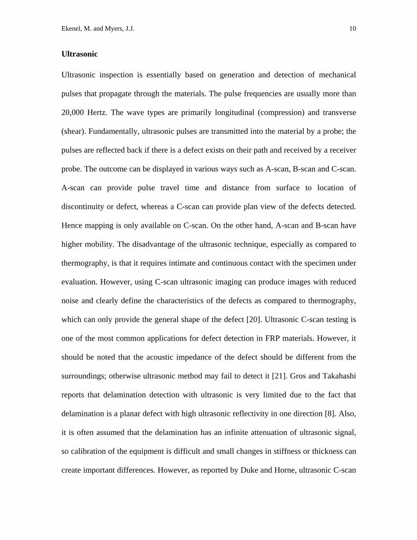
Ultrasonic
Ultrasonic inspection is essentially based on generation and detection of mechanical
pulses that propagate through the materials. The pulse frequencies are usually more than
20,000 Hertz. The wave types are primarily longitudinal (compression) and transverse
(shear). Fundamentally, ultrasonic pulses are transmitted into the material by a probe; the
pulses are reflected back if there is a defect exists on their path and received by a receiver
probe. The outcome can be displayed in various ways such as A-scan, B-scan and C-scan.
A-scan can provide pulse travel time and distance from surface to location of
discontinuity or defect, whereas a C-scan can provide plan view of the defects detected.
Hence mapping is only available on C-scan. On the other hand, A-scan and B-scan have
higher mobility. The disadvantage of the ultrasonic technique, especially as compared to
thermography, is that it requires intimate and continuous contact with the specimen under
evaluation. However, using C-scan ultrasonic imaging can produce images with reduced
noise and clearly define the characteristics of the defects as compared to thermography,
which can only provide the general shape of the defect [20]. Ultrasonic C-scan testing is
one of the most common applications for defect detection in FRP materials. However, it
should be noted that the acoustic impedance of the defect should be different from the
surroundings; otherwise ultrasonic method may fail to detect it [21]. Gros and Takahashi
reports that delamination detection with ultrasonic is very limited due to the fact that
delamination is a planar defect with high ultrasonic reflectivity in one direction [8]. Also,
it is often assumed that the delamination has an infinite attenuation of ultrasonic signal,
so calibration of the equipment is difficult and small changes in stiffness or thickness can
create important differences. However, as reported by Duke and Horne, ultrasonic C-scan

Ekenel, M. and Myers, J.J. 11
can be successfully used to detect concentrated areas of porosity, resin starved regions, or
matrix cracking [18].
Franklin et al., applied ultrasonic longitudinal waves in through-transmission along the
radial direction of FRP wrapped concrete cylinders, which were subjected to
environmental conditions such as freeze-thaw, alkaline solution, dry heat and water
immersion [22]. The ultrasonic testing was conducted with ten cycle sine pulse of 400
volts peak-to-peak amplitude to excite the 250 kHz central frequency transducers. They
have reported that ultrasonic testing in the radial direction captured the debonding effect
between the wrap and concrete.
Kaczmarek conducted a research to determine delaminations in a carbon-epoxy
composite material under static and fatigue loading [23]. They have applied transmission-
mode ultrasonic testing with high-frequency longitudinal waves. The ultrasonic results
were compared by X-ray radiography results. The results of ultrasonic were comparable
to those observed by radiography, which shows the feasibility of the system used to
detect delaminations in composite materials. Castaings performed delamination detection
tests on carbon fiber composite plates via a single sided, air coupled ultrasonic NDT
system using Lamb waves [24]. The air-coupled transmitter is oriented at a specific angle
to produce pure Lamb waves. The advantage of Lamb waves over normal incident is that
they are capable of traveling for longer distance. They concluded that delaminations have
been successfully detected within layers using air-coupled ultrasonic transducers. Kundu
et al. used two ultrasonic techniques to detect delaminations between the GFRP plate and
the concrete surface [7]. These techniques consisted of utilization of longitudinal waves
and Lamb waves (L-scan) using relatively low frequencies (below 1 MHz).

Ekenel, M. and Myers, J.J. 12
Delaminations were formed by applying no epoxy the some certain areas of about 50 mm
diameter. Their conclusion was that both Lamb wave scanning (L-scan) and longitudinal
wave scanning (pulse-echo and tone bust C-scan) can detect the delaminations between
GFRP/concrete interfaces. They have recommended Lamb wave scanning technique to
be the superior technique due to the fact that C-scan technique is sensitive to the glue and
GFRP plate property variations; whereas L-scan image is insensitive to the small
variations in the glue and plate properties.
Acousto-ultrasonic
Acousto-ultrasonic (AU) evaluation method has also been implemented to detect
damages in FRP materials used in structural applications. The AU is a combination of
acoustic-emission monitoring and ultrasonic characterization. AU method functions by
inducing acoustic pulses using a transducer, a second transducer to detect the portion of
these pulses that has propagated away from the point of excitation [18]. These acoustic
pulses travel through the material and are reflected by the different interfaces inside the
sample. Travillion et al. applied a theoretical model and experimental work to
demonstrate the feasibility of using the acousto-ultrasonic technique in the inspection of
FRP/concrete interface with surface defects [25]. Surface defects were generated by
inserting Teflon wafers between the concrete substrate and the FRP laminate. They used
rubber-tire differential rolling sensors. Rubber tires acted as a dry couplant between the
sensor and the surface and maintained a constant distance which reduced the reflected
amplitude changes due to contact variation between the sensor and the member under
test. Delaminations were viewed via A and C-scan imaging. Test results and field
applications revealed that AU technique can detect disbonds of 6 mm in diameter. System

Ekenel, M. and Myers, J.J. 13
is capable of generating A and C-scan images of defects. Two of the limitations they have
encountered during the field testing were unable to scan wide areas due to half-scale
model they have used and the splintered fibers at the edge of the FRP strips which also
limited the scanning area. Godinez et al. applied AU technique successfully in detection
delamination between fiber reinforced polymer fabric and concrete at a retrofitted
structural member [26]. Guided wave generation, produced by using an array of angled
sensors, is the technology behind their system. They have concluded that the
delaminations can be detected using AU technology independent of fiber type, such as
glass or carbon. This has also been validated in the field by Ekenel et al. through
comparative NDT techniques (see Fig. 6) [27]. Acousto-ultrasonic assessment of
composites and laminates were standardized by ASTM E1495-02: “Standard Guide for
Acousto-Ultrasonic Assessment of Composites, Laminates and Bonded Joints” [28].
Impact-echo
Impact-echo method is another NDE method used for damage detection in FRP materials.
The impact-echo methods works just like majority of NDE methods by sending stress
waves (impact-generated stress waves such as sound) across the material under
investigation and observing the reflected waves at any property chance throughout the
material (such as delaminations). ASTM C1383-04 (Standard Test Method for Measuring
the P-Wave Speed and the Thickness of Concrete Plates Using the Impacy-Echo Method)
defines impact-echo method as an NDT method based on the use of a short-duration
mechanical impact to generate transient stress waves and the use of a broadband
receiving transducer placed adjacent to the impact point [28]. The advantage of this
technique is that it is a single-sided test; only one side of the material should be

Ekenel, M. and Myers, J.J. 14
accessible for testing [29]. The impact-echo method can be used successfully in concrete
bridge decks and slabs to locate cracks, voids, honeycombing and delaminations [30].
The feasibility of this method has also been validated in the field by Maerz et al. through
comparative NDT techniques [31].
Microwave
Delamination detection in layered composites or at the FRP-concrete interface has been
successfully implemented via near-field microwave technology in recent years.
Microwave frequency may change between 300 MHz and 300 GHz with wave lengths
between 1 mm and 1 m. Microwave ND testing functions by transmitting microwaves
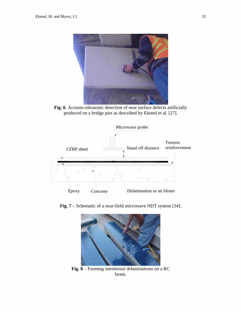
and capturing the reflected waves like most of the NDT techniques (see Fig. 7). The
transmitted and reflected waves are first plotted and superposed by fixing maximum and
minimum points, which is called as standing wave. A defect between layers can be
detected if the standing wave shifts by changing its phase angle and amplitude.
Microwave NDE is also proven to provide satisfactory results in thickness measurements
in non-metallic materials, monitoring degree of polymer cure and concrete curing,
concrete moisture and water-to-cementitious ratio detection, monitoring density of
ceramics besides delamination detection between FRP fabric and concrete substrate.
However, microwaves are not suitable for internal inspection of metals due to complete
reflection of all waves (penetration is possible to only a micro millimeter in distances).
Hughes et al. performed tests on Microwave detection of delaminations between carbon
fiber reinforced polymer composite and concrete [4]. Delaminations between CFRP
fabric and concrete were formed by placing thin slices of foam which were attached to
the concrete surface by a thin layer of Teflon tape. Two major aspects of their research

Ekenel, M. and Myers, J.J. 15
were determination of orientation of the waves with respect to fiber orientation and stand-
off distance between probe and the concrete surface. Fiber orientation is important
because the reflection of signal totally depends on it; if the field polarization is parallel to
the fiber orientation, then the signal will be completely reflected. Stand-off distance was
important to eliminate surface roughness problems and increase sensitivity (see Fig. 7).
The tests were carried out with a waveguide between 10.5 GHz and 24 GHz. Results
proved that such defects can be successfully detected using near-field microwave
techniques. Kim et al. monitored delaminations (disbonds/air voids) between an FRP-
jacket and the concrete substrate via electromagnetic imaging technology with frequency
between 8.2 GHz and 12.4 GHz, because air voids produce reflections of electromagnetic
wave [3]. The depth of delaminations was obtained by microwave subsurface imaging
technology with a frequency of 10 GHz. Delaminations were obtained via inserting a
small block or a small strip of Styrofoam in the bonding interface between the FRP and
concrete substrate, because the Styrofoam has same dielectric property as that of the air.
They reported that the locations and areas of these delaminations were successfully
detected using microwave-based surface scanning. Akuthota et al. investigated disbonds
and delaminations between CFRP fabric and concrete substrate using near-field
microwave technique [32]. The experiments were conducted using custom made
reflectometers at 10 GHz and 24 GHz. Test results indicated that delaminations as small
as 1 cm2 can be detected, which are much smaller than the required minimum detection
size referred by ACI 440.2R-02. Moreover, it has also been demonstrated that this
technique can successfully evaluate the quality of repair of a delamination by epoxy
injection, which is also a requirement of ACI 440.2R-02.

Ekenel, M. and Myers, J.J. 16
Ground penetrating radar
Ground penetrating radar (GPR) functions by emitting electromagnetic wave of
frequency ranging between 500 MHz and 1.5 GHz from an antenna; part of which is
reflected back if there is a discontinuity exists in an object [21]. It has been used widely
in civil applications for many years such as inspecting wood, concrete and masonry. It is
highly mobile and no intimate contact is required; however, there is little information
available on its validity if applied to composite materials. It is generally not
recommended for thin materials because near-surface defects are very difficult to detect
due to strong interference between signal reflected off the front surface and signals
originated from near-surface depths [21]. Jackson et al. applied ground penetrating radar
technique to inspect the delaminations between the FRP and concrete substrate [16].
They concluded that the GPR technique can easily detect defects within concrete;
however, in order to detect very shallow defects such as delaminations between the FRP
and concrete substrate, a high frequency antenna (such as 2 GHz) is required.
Foucault currents (Eddy current or Induced current)
The eddy current method requires a source of varying magnetic field (often caused by an
AC coil) and a sensor to detect small changes in magnetic field. Defects can be detected
if there is a change in magnetic field. It should be noted that defects should have adequate
dimensions to affect the magnetic field; otherwise they remain undetected. Even though
most composites are not suitable for eddy current testing, carbon fiber reinforced
polymers can be inspected because electrons can move along carbon atoms, which limits
this method for inspection of only carbon fiber related problems. Kaiser et al. reports that
eddy current testing of composite materials do not require any intimate contact as a plus

Ekenel, M. and Myers, J.J. 17
side; on the other hand, it is difficult to interpret and only sensitive to conductive
materials, hence matrix-related defects remain undetected [12]. Gros and Takahashi
applied Foucault currents (eddy current) to detect delaminations between carbon
fiber/epoxy laminates and reported that this technique provides successful application in
delamination detection between plies if correctly applied, unlike what most of the
researchers who stated as Foucault currents are insensitive to delaminations [8]. Mook et
al. also reported that eddy-current scanning system based on special probes can visualize
fiber orientation, local imperfections like fiber fraction, resin rich zones, delaminations
and impact damages [33].
Laser shearography
Laser shearography is a large area non-contact inspection method, which is faster than
contact scanning via ultrasonic C-scan. It can record images digitally and can be used
with a variety of excitations such as heating and acousto-loading [5]. Kaiser states the
advantages of shearography as having high detail even if operated at full-field level, no
intimate contact required and having excellent sizing capabilities [12]. He lists the
disadvantages as having relatively high environmental stability and the structure must be
exposed to controlled loading conditions. It was reported by Newman and Zweben that
shearography NDT is able to detect delaminations (disbonds) between carbon fiber
reinforced FRP layers and concrete substrate under thermal excitation [5].
EXPERIMENTAL VERIFICATION
The Center for Infrastructure Engineering Studies (CIES) at the University of Missouri-
Rolla (UMR) has studied the effect of delaminations between FRP fabric and concrete
substrate on structural performance of FRP strengthened structural members. First, three

Ekenel, M. and Myers, J.J. 18
RC beams were prepared, pre-cracked under four point bending loading and strengthened
with CFRP fabrics [34]. The CFRP fabric was 203 mm wide and 0.165 mm thick and was
applied as single ply throughout the length of the test span. CFRP fabrics were attached
to the tension face of test specimens. Delaminations were produced in all three beams.
Delaminations were formed right after the final layer of epoxy application when the
epoxy was still in fresh state. Three spots on the laminate were pinned and a small
amount of pressured air compressed beneath the CFRP sheet, which created
delaminations (see Fig. 8). A spike-roller rolled around the perimeter of delaminations
was used to form the final shape of the delaminations. The delaminations were formed
with one at mid-span, and two directly outside the constant moment zone as shown in
Fig. 1. The total delamination areas were measured and divided by the total CFRP fabric
area to obtain the percent of total delamination area. The percent delamination areas were
3.85, 3.00 and 4.20 for each beam; which were consistent with ACI 440.2R-02
requirements (less than 5%). All beams were tested under fatigue loading.
All of the delaminations were tested via near-field microwave measurement system at
initial, 500000, 1-million and 2-million cycles. Test set-up is illustrated in Fig. 9. They
have also been inspected visually and by applying tap-test (see Fig. 3). Tests were
terminated after 2-million cycles. It was observed that the flexural stiffness of CFRP
strengthened beams were significantly affected because of the presence of the
delaminations under fatigue loading [35]. The scanned images showed that the
microwave technology can successfully detect and image the delaminations. Several
unintentional images have also been detected. The microwave images showed that the

Ekenel, M. and Myers, J.J. 19
area of the delamination did not change significantly as a function of increased loading
[34]. These beams are still under conditioning for long-term study.
Two additional beams were prepared to observe the effect of delaminations on flexural
strength. One beam contained three delaminations with the percent delaminations area of
5%, which was also consistent with ACI 440.2R-02 requirements (less or equal to 5%).
Delaminations were formed same as described previously (see Figs. 1 and 8). The beams
were tap tested in order to determine whether they contain delaminations and the
locations of the delaminations. One of the delaminations beneath one of the loading
supports was also equipped with two strain gages; one placed at the center of
delamination, another one attached to the disbond interface of delamination-concrete to
observe the behavior of delamination. These two beams were tested under static four-
point bending. Fig. 10 shows the load versus mid-span displacement curves of the two
beams tested. As Fig. 10 shows, the beam with delaminations exhibited 9% reduction in
the ultimate strength as compared with the beam with no delaminations. The reduction in
the ultimate displacement was 6% (Fig. 10) as compared to the beam with no
delaminations. Fig. 11 shows the strain readings on CFRP fabric and steel at mid-span for
the beams with and without delamination, in which an insignificant difference can be
observed among strain readings. Fig. 12 shows the readings which were recorded over
CFRP fabric at mid-span and at the corner and center of one of the one of the
delaminations located beneath one of the loading supports. As seen in this figure, the
strain reading at the center of the delamination at the load level of 65 kN was 37% lower
than the strain reading at the corner of the delamination at the same load level.

Ekenel, M. and Myers, J.J. 20
Figs. 10 and 11 demonstrate that the displacement measurements of CFRP strengthened
structures using nondestructive-load-testing methods performed at service-load levels
(usually 40% of the predicted ultimate strength) cannot clearly indicate the presence of
delaminations since these test results did not exhibit any distinctive difference among
strain readings in steel and CFRP, or in displacement readings; however, more research is
warranted.
Another verification application was performed in a bridge structure which was
sponsored by Missouri Department of Transportation (MoDOT), USA [36]. Fifteen
CFRP laminates with dimensions of 508 mm x 610 mm were installed on various spots of
abutment and bents for this investigation. These locations were sacrificial places which
were specially selected to not affect the structural integrity of the bridge. Delaminations
were formed on several spots of these CFRP panes by applying pressurized air beneath
CFRP sheet while epoxy was in fresh state (see Fig. 2 and Fig. 13). Two of the
delaminations were placed near a splash zone area where the water level in the river
fluctuates to investigate the effects of freeze-thaw and excessive moisture (see Fig. 14).
Moisture migration may fill the air-pockets and then could be subjected to freeze-thaw
cycles during the winter; ultimately causing failure in the repair system. Moisture can
significantly affect the bond strength of the composite, although it does not influence the
strength and modulus of carbon fibers [2]. All delaminations at these locations were
scanned using microwave technology, impact-echo and acousto-ultrasonic (AU) as well
as visual inspection and tap tests. The following items have been observed:
1. Even though visual and tap test were fast, detected large areas in a short period of
time and located some of the delaminations, they could not located many small

Ekenel, M. and Myers, J.J. 21
blisters and they did not provide quantitative and objective information such as depth
and size of the delaminations.
2. The AU system demonstrated its ability of detecting delaminations between FRP and
concrete substrate without being influenced by the interior reinforcement, coarse
aggregate or the surface orientation (whether vertical or horizontal) [27]. Prior
marking of CFRP panel was required to provide scan-guidelines during inspection.
AU testing was performed in a matter of minutes to scan a 305 mm x 305 mm area.
The calibration of apparatus took minimal time with little expertise, and test results
were easy to interpret. The delaminations were imaged instantly on the display of the
apparatus. However, there was not sufficient information available about the depth of
the delaminations.
3. The CFRP panels have to be marked with a mesh of 25 mm x 25mm before testing
with impact-echo testing. The impact-echo tests also successfully identified the
artificial delaminations; however, delamination measurements were time consuming
[31].
4. Microwave measurements were also very successful in detecting intentional and
unintentional delaminations [37]. It was feasible to have a close idea of the depth and
the dimensions of the delamination [37]. However, the current microwave test
apparatus needed skilled personnel and tests were time consuming.
Comparative studies of these techniques for this field related case study will continue
through May 2008 to monitor any changes in the defects as well as provide additional
NDE system comparisons.

Ekenel, M. and Myers, J.J. 22
SUMMARY
The results of this literature review and investigation shows that currently there is no
available NDT method which can scan large scale FRP strengthened areas for
delaminations between FRP fabric and concrete substrate in a short period of time; even
though the non-destructive evaluation methods of thermography, microwave, ultrasonic,
acousto-ultrasonic and impact echo showed promising results in successfully detecting
and locating delaminations (air-blisters) between FRP fabric and concrete substrate. The
current microwave NDT appeared to give more detailed information about the defect
location and dimension even though the test apparatus requires trained and skilled
personnel and consumes relatively more time. Acousto-ultrasonic and impact-echo
showed a lightweight and more user-friendly apparatus; however, it cannot provide
detailed information like microwave technology. Laser shearography, ground penetrating
radar and eddy current test methods have also been tested in detecting such defects,
especially between FRP plies; however, more work is required in these fields. The
authors believe that the above mentioned technologies can be very useful defect detection
methods where the bond property is extremely critical and where the tap-test and visual
inspection provides signs of delamination in a FRP fabric strengthened structural
member. These tools also hold great promise as a confirmation tool for defect repair and
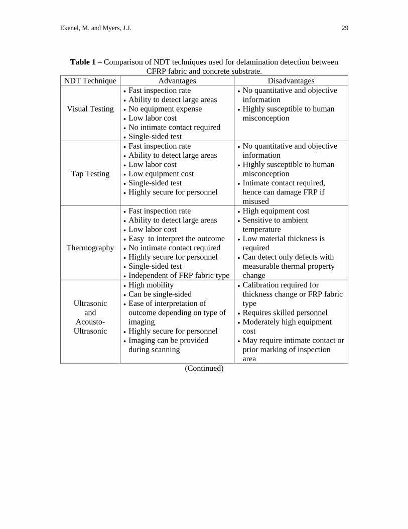
injection verification. Table 1 shows the overall comparison among NDT techniques
presented in this paper.

Ekenel, M. and Myers, J.J. 23
REFERENCES
1. Meier, U., and Kaiser, H., “Strengthening of Structures with CFRP Laminates,”
Advanced Composite Materials in Civil Engineering Structures: Proceedings of the
Specialty Conference, Nevada, pp. 224-232, 1991.
2. Kaiser H. and Karbhari, V.M., “Identification of Potential Defects in the
Rehabilitation of Concrete Structures with FRP Composites,” International Journal of
Materials and Product Technology, Vol. 19, No. 6, pp. 498-520, 2003.
3. Kim, Y.J., Flaviis, F., Jofre, L., Feng, M.Q., “Microwave-based NDE of FRP-
Jacketed Concrete Structures,” 46th International SAMPE Symposium, California, pp.
439-450, May 2001.
4. Hughes, D., Kazemi, M., Marler, K., Zoughi, R., Myers, J.J., and Nanni, A.,
“Microwave Detection of Delaminations Between Fiber Reinforced Polymer (FRP)
Composite and Hardened Cement Paste,” Proceedings for the 28th Qualitative
Nondestructive Evaluation Conference, Brunswick, Maine, V. 21, pp. 512-519, July-
August 2001.
5. Newman, J. and Zweben C., “Nondestructive Inspection of Composite-Strengthened
Concrete Structures,” 47th International SAMPE Symposium, Vol. 47, May 2002.
6. Shih J.K., Tann, D.B., Hu, C.W., Delapk, R., and Andreou, E., “Remote Sensing of
Air Blisters in Concrete-FRP Bond Layer Using IR Thermography” International
Journal of Materials and Product Technology, V. 19, Nos. 1-2, pp. 174-187, 2003.
7. Kundu, T., Ehsani, M., Maslov, K. I., and Guo D., “C-scan and L-scan Generated
Images of the Concrete/GFRP Composite Interface,” NDT&E International, V. 32,
pp. 61-69, 1999.

Ekenel, M. and Myers, J.J. 24
8. Gros, X.E., and Takahashi, K., “Non-destructive Characterization of Delaminated
Areas at Interfaces Between Plies in Carbon Fiber/epoxy Laminates with Foucault
Currents,” Composite Interfaces, V. 7, N. 3, pp. 177-192, 2000.
9. ACI Committee 440.2R-02. “Guide for the design and construction of externally
bonded FRP systems for strengthening concrete structures” American Concrete
Institute, Farmington Hills, MI, 2002.
10. Miceli, M., Horne, M.R., and Duke, C.D., “Health Monitoring of FRP Bridge Decks”
Advanced Nondestructive Evaluation for Structural and Biological Health
Monitoring, Proceedings of SPIE, V. 4335, pp. 100-105, 2001.
11. Starnes, M.A., Carino, N.J., and Kausel, E.A., “Preliminary Thermography Studies
for Quality Control of Concrete Structures Strengthened with FRP Composites,”
Journal of Materials in Civil Engineering, ASCE, Vol. 15, No. 3, May/June 2003, pp.
266-273.
12. Kaiser H. and Karbhari, V.M., “Non-destructive Testing Techniques for FRP
Rehabilitated Concrete-II: An Assessment,” International Journal of Materials and
Product Technology, Vol. 21, No. 5, pp. 385-401, 2004.
13. Wong, B. S., Tui C. G., Bai, W., Tan, P. H., Low, B. S., and Tan K.S.
“Thermographic Evaluation of Defects in Composite Materials,” Insight: Non-
destructive Testing and Condition, V. 41, No. 8, pp. 504-509. 1999.
14. Raj, B., Subramanian, T.J., “Non-destructive Testing of Welds,” Narosa Pub. House
at 1947, Distrubuted to North America by ASM International, c2000.
15. Maldague, X., “Introduction to NDT by Active Infrared Thermography,” Materials
Evaluation, Vol. 60, No. 9, p. 1060-1073, September 2002.

Ekenel, M. and Myers, J.J. 25
16. Jackson D., Islam, M., Alampalli, S., “Feasibility of Evaluating the Performance of
Fiber Reinforced Plastic (FRP) Wrapped Reinforced Concrete Columns Using
Ground Penetrating Radar (GPR) and Infrared (IR) Thermography Techniques,” An
NDT Conference on Structural Materials Technology IV, Edited by S. Alampalli, p.
390-395, February/March 2000.
17. Senthilnath, P.S., Belarbi, A., and Myers, J.J., “Performance of CFRP Strengthened
RC Beams in the Presence of Delaminations and Lap Splices under fatigue Loading,”
Proceedings-Composites in Construction: 2001 International Conference, Porto,
Portugal, October 2001.
18. Duke, J. C., Horne, M. R., “NDE of Polymeric Composite Material Bridge
Components,” Proceedings of SPIE, the International Society for Optical
Engineering, Vol. 3400, p. 18-123, 1998.
19. Hag-Elsafi, O., Alampalli, S., and Kunin, J., “In-Service Evaluation of a Reinforced
Concrete T-Beam Bridge FRP Strengthening System,” Composite Structures, Vol.
64, p. 179-188, 2004.
20. Wong, B. S., Chua, F. M., Ow, W. Y. and Tui C. G., “Non-destructive Testing of
Fibre Reinforced Composites and Honeycomb Structures,” Proceedings of Defense
Materials and Mechanics Seminar, Singapore. 1999.
21. Kaiser H., Karbhari, V.M., and Sikorsky, C., “Non-destructive Testing Techniques
for FRP Rehabilitated Concrete-I: A Critical Review,” International Journal of
Materials and Product Technology, Vol. 21, No. 5, pp. 349-384, 2004.

Ekenel, M. and Myers, J.J. 26
22. Franklin, R., Halabe, U. B., Lopez-Anido, R., and Kshirsagar, S., “Condition
Assessment of FRP Wrapped Concrete Members Using Ultrasonics,” Nondestrcutive
Testing & Evaluation, V. 17, pp. 59-78, 2001.
23. Kaczmarek, H., “Ultrasonic Detection and Visualization of Critical Damage in
Carbon-Epoxy Materials,” La Recherche Aerosp., English version, Issue: 2, 1990.
24. Castaings, M., Cawley, P., Farlow, R., and Hayward, G., “Single Sided Inspection of
Composite Materials Using Air Coupled Ultrasound,” Journal of Nondestructive
Evaluation, Vol. 17, No. 1, 1998.
25. Trovillion J. C., Godinez-Azcuaga V. F. and Finlayson, R. D. “A Nondestructive
Evaluation Technique for Fiber Reinforced Polymer (FRP) Composites Using
Acoustic Guided Waves (AGW),” 24th Army Science Conference Proceedings, GP-
11, Orlando Florida, 2004.
26. Godínez, V., Delamere, M.W., Hatcher, T., Shen, W., Aston, R., Finlayson, R.D., and
Trovillion, J., “A Nondestructive Evaluation System for Inspection of Fiber
Reinforced Polymer Reinforced Concrete Structures,” proceedings of the 35h
International SAMPE (Society for the Advancement of Material and Process
Engineering) Technical Conference, Dayton, OH, Vol. 35, Sept 28-Oct. 2, 2003.
27. Ekenel, M., Galati, N., Myers, J.J., Nanni, A., and Godinez, V., “Acousto-Ultrasonic
Technology for Non-destructive Evaluation of CFRP Strengthened Concrete Bridge
Members, Journal of the Transportation Research Board, No. 1928, Design of
Structures 2005, pp. 245-251.
28. ASTM International, Annual Book of ASTM Standards, 2004.

Ekenel, M. and Myers, J.J. 27
29. Tawhed, W. F., Gassman, S. L., “Damage Assessment of Concrete Bridge Decks
using Impact-Echo Method,” ACI Materials Journal, V. 99, No. 3, May-June 2002.
30. Sansalone, M.J., and Street, W.B., “Impact-Echo, Nondestructive Evaluation of
Concrete and Masonry,” Bullbrier Press, Ithica, N.Y., pp. 339, 1997.
31. Maerz, N., Galecki, G., and Nanni, A., “Experimental Non-destructive Testing of
FRP Materials, Installation, and Performance, Dallas Bridge, Missouir, USA,”
Proceedings of the 16th World Conference on Nondestructive Testing, Montreal,
Canada, August 2004.
32. Akuthota B., Hughes, D., Zoughi, R., Myers, J.J., and Nanni, A., “Near-field
Microwave Detection of Disbond in Carbon Fiber Reinforced Polymer Composites
Used for Strengthening Cement-Based Structures and Disbond Repair Verification,”
Journal of Materials in Civil Engineering, ASCE, V. 16, No. 6, pp. 540-546,
November/December 2004.
33. Mook, G., Lange, R., and Koeser, O., “Non-destructive Characterization of Carbon-
Fiber-Reinforced Plastics by Means of Eddy-Current,” Composites Science and
Technology, Vol. 61, p. 865-873, 2001.
34. Ekenel, M., Stephen, V., Myers, J.J., Zoughi, R., “Microwave NDE of RC beams
Strengthened with CFRP Laminates Containing Surface Defects and Tested under
Cyclic Loading,” Proceedings of the 16th World Conference on Nondestructive
Testing, Montreal, Canada, August 2004.
35. Ekenel, M., and Myers, J.J. “Effect of Environmental Conditioning and Sustained
Loading on the Fatigue Performance of RC Beams Strengthened with Bonded CFRP

Ekenel, M. and Myers, J.J. 28
Fabrics,” American Concrete Institute – Materials Journal, Submitted September
2004.
36. Ekenel, M., Myers, J.J., “Nondestructive Testing of Dallas County Bridge in
Missouri, USA,” Proceedings of the 16th World Conference on Nondestructive
Testing, Montreal, Canada, August 2004.
37. Stephen, V., Kharskovsky, S., Nadakuduti, J., Zoughi, R., “Microwave Field
Measurement of Delaminations in CFRP Concrete Members in a Bridge,”
Proceedings of the 16th World Conference on Nondestructive Testing, Montreal,
Canada, August 2004.
Ekenel, M. and Myers, J.J. 29
Table 1 – Comparison of NDT techniques used for delamination detection between
CFRP fabric and concrete substrate. NDT Technique Advantages Disadvantages
Visual Testing
• Fast inspection rate • Ability to detect large areas • No equipment expense • Low labor cost • No intimate contact required • Single-sided test
• No quantitative and objective information
• Highly susceptible to human misconception
Tap Testing
• Fast inspection rate • Ability to detect large areas • Low labor cost • Low equipment cost • Single-sided test • Highly secure for personnel
• No quantitative and objective information
• Highly susceptible to human misconception
• Intimate contact required, hence can damage FRP if misused
Thermography
• Fast inspection rate • Ability to detect large areas • Low labor cost • Easy to interpret the outcome • No intimate contact required • Highly secure for personnel • Single-sided test • Independent of FRP fabric type
• High equipment cost • Sensitive to ambient
temperature • Low material thickness is
required • Can detect only defects with
measurable thermal property change
Ultrasonic and
Acousto-Ultrasonic
• High mobility • Can be single-sided • Ease of interpretation of
outcome depending on type of imaging
• Highly secure for personnel • Imaging can be provided
during scanning
• Calibration required for thickness change or FRP fabric type
• Requires skilled personnel • Moderately high equipment
cost • May require intimate contact or
prior marking of inspection area
(Continued)

Ekenel, M. and Myers, J.J. 30
Table 1 – Comparison of NDT techniques used for delamination detection between
CFRP fabric and concrete substrate (continued). NDT Technique Advantages Disadvantages
Impect-Echo • Moderately slower inspection rate
• Lightweight and user-friendly equipment
• Ease to interpret outcome • Single-sided test • Low labor cost • Safety of personnel
• Moderately high equipment cost
• Prior marking of inspection area may be required
• Less effective for small delaminations (< 1 in2)
• Imaging cannot provide informative outcome
Microwave • Can detect any size delamination successfully
• Can provide highly detailed images such as depth and the area of the delamination
• Safety of personnel • Single-sided test • Imaging can be provided
during scanning
• High equipment and labor cost, requires highly skilled personnel
• Intimate contact may not required; however, requires determination of stand-off distance
• Slower inspection rate and time consuming testing
• Prior marking may be required

Fig. 1 – Test beam with delaminations
between CFRP fabric and concrete substrate [34].
Fig. 2 – Delaminations between CFRP fabric and concrete substrate on a bridge
structure [36].
Fig. 3 – Application of tap-test with a steel bar.
Fig. 4 – Thermographic image of a
delamination prior to fatigue cycling [17].
Fig. 5 – Thermographic image of a delamination after 2 Million fatigue cycles
[17].
Ekenel, M. and Myers, J.J. 32
Fig. 6. Acousto-ultrasonic detection of near surface defects artificially produced on a bridge pier as described by Ekenel et al. [27].
Delamination or air blister
CFRP sheet
Concrete
Microwave probe
Epoxy
Stand off distanceTension reinforcement
Fig. 7 – Schematic of a near-field microwave NDT system [34].
Fig. 8 – Forming intentional delaminations on a RC beam.

Ekenel, M. and Myers, J.J. 33
Fig. 9 – Microwave NDT of delamination on a RC beam as described by Ekenel et al. [34].
0 10 20 30Mid-span Displacement (mm)
0
20
40
60
80
Load
(kN
)
Without DelaminationWith Delamination
Fig. 10 – Load vs. mid-span displacement curves of beams with
and without delaminations.

Ekenel, M. and Myers, J.J. 34
0 0.4 0.8 1.2Strain Readings (%)
0
20
40
60
80
Load
(kN
)
Steel-No DelaminationCFRP-No DelaminationSteel-DelaminationCFRP-Delamination
Fig. 11 – Mid-span strain readings of the beams with and without delaminations. Strains were measured over CFRP fabric and Steel
reinforcement of the beams with and without delamination.
0 0.4 0.8 1.2Strain Readings (%)
0
20
40
60
80
Load
(kN
)
Over DelaminationCorner DelaminationMid-span
Fig. 12 – Strain readings of the beam with delaminations. Strain
readings were measured at the middle of the delamination, corner of the delamination, and at the mid-span of the beam over perfectly bonded
CFRP fabric. The delamination that readings were performed was located beneath one of the loading supports.

Ekenel, M. and Myers, J.J. 35
Fig. 13 – Forming intentional delaminations on a bridge structure [36].
Fig. 14 – CFRP fabric with near surface defects applied on a
bridge structure near splash/water zone [36].