nonlinear analysis of degenerated fgm shells · plates where the von karman theory is used for...
TRANSCRIPT

International Journal of Applied Engineering Research ISSN 0973-4562 Volume 12, Number 21 (2017) pp. 11511-11522
© Research India Publications. http://www.ripublication.com
11511
Nonlinear analysis of degenerated FGM shells
B. Amieur a, M. Djermane a, F. Hammadi b
a Reliability of Materials and Structures Laboratory, University Of Bechar, Algeria. b Laboratory of Mechanics: Modelling and experimentation L2ME, University of Bechar, Algeria.
1,2,3Orcid: 0000-0002-9032-5380, 0000-0003-1267-1787, 0000-0002-7504-4580
Abstract
In this work we deal with nonlinear behavior of functionally
graded material for cylindrical panel and spherical structure.
The formulation chosen in this work is based on Von Karman
theory for large transverse deflection with the layer-by-layer
approach. The mechanical properties are assumed to vary
continuously through thickness direction according to the
volume fraction of the constituents by a simple power law
distribution. The shell element developed is based on a nine
nodes degenerated finite element formulation with height
order shear deformation theory. The effect of variations of
volume fractions and shell geometrical parameters are studied,
the influence of elastoplasticity is also the subject of this
work. Convergence tests and comparison studies have been
carried out to establish the efficiency of the present model.
Keywords: Composite, nonlinear, FGM, DDSE
INTRODUCTION
Because of their strength to weight ratio, high rigidity, long
life of fatigue, resistance to electrochemical corrosion and
other superior properties of composite materials, laminates
have been used increasingly in variety industrial areas.
The design of the structures with better thermal and
mechanical properties in addition to high stiffness to weight
ratios and strength to weight ratios can be obtained with
adaptation of the laminated composite structures but because
of the sharp change in these properties at the interface
between two adjacent layers causes initiation to delamination
which can be avoided if the different properties continuously
vary across the thickness and thus the use of FGM can
become an important problem for advanced structural
applications.
Recently, functionally graded materials (FGM) materials,
which are readily manufactured from a mixture of a metal and
a ceramic characterized by a continuous change of mechanical
properties in the direction of thickness, have emerged as a
new class of materials.
In literature many researchers studied static, dynamic and
nonlinear behavior for elastic FGM structures in the past few
years, only some of them are cited in this paper:
For example in 2006, Ashraf and Zenkour [1] presented the
static response for simply supported functionally graded
rectangular plates subjected to a transverse uniform load. In
2009 M. Simsek presented a static analysis of a functionally
graded simply-supported beam subjected to a uniformly
distributed load by using Ritz method within the framework of
Timoshenko and the higher order shear deformation beam
theories [2] and the mechanical behavior of FGM plates under
transverse load is given by Chi and Chung [3],[4].
the research were continuing to take into account the
nonlinear problems as is presented by Shen [5] when treated
nonlinear bending analysis for a simply supported functionally
graded rectangular plate subjected to transverse uniform load
or sinusoidal load. In this studie the Galerkin technique is
employed to determine load deflection and load bending
deflection and load bending moments. A higher order theory
for studying the bending response of functionally graded
plates where the Von Karman theory is used for obtaining the
approximate solutions for nonlinear bending is proposed by
Lee et al. [6].
The temporal problems were the subject of several studies,
including that of Amini et al. [7] which is summarized in the
analysis of the free vibration of FGM plates on elastic
foundations using three-dimensional linear elasticity theory,
Sundararajan et al. [8] investigated the nonlinear free flexural
vibrations of FGM rectangular and skew plates in thermal
environments, respectively. Pradyumna et al. [9] analyzed in
2008 the free vibration of functionally graded curved panels
using a higher-order C0 finite element formulation.
Then nonlinear vibrations and dynamic response were studied
by Huang and Shen [10] .Natural frequencies, compressive
buckling loads, buckling temperature and bending deflections
and stresses of FGM sandwich plates based on sinusoidal
shear deformation plate theory and the nonlinear dynamic
response of sandwich plates resting on elastic foundations in
thermal environments are analyzed and calculated by Zenkour
[11]; Zenkour and Sobhy [12]; Zenkour and Alghamdi [13]
and Zhen-Xin Wang et al. [14]. And Thermal post buckling
and vibration behaviour of FGM plates were studied by Park
and Kim [15].
In order to trace the equilibrium path beyond critical points, a
more general incremental control strategy is needed, in which

International Journal of Applied Engineering Research ISSN 0973-4562 Volume 12, Number 21 (2017) pp. 11511-11522
© Research India Publications. http://www.ripublication.com
11512
displacement and load increments are controlled
simultaneously. This strategy known by controlled arc length
method was not used in the case of composite materials
according to the literature to date, from this documents and
researches also in my knowledge; the elastic-plastic analysis,
which is also the subject of this work, is not treated in the
FGM type case of composites materials only by Moita et all in
2016 [16].
EFFECTIVE MATERIAL PROPERTIES OF FGMS:
In the first we consider a simple square FGM plate as shown
in the Fig.1.
Figure 1: FGM plate.
The mechanical properties are determined according to the
volume fraction when we consider that the plate is made up of
a mixture of the ceramic as top face sheet and the metal as
bottom face sheet as following[17][18]:
mmcc VPVPzP (1)
Where zP is the effective properties which can be the
Young modulus zE , the Poisson ratio z , the yield stress
zY or the density z , the thermal expansion coefficient
𝛼(𝑧) or thermal conductivity 𝑘(𝑧) .
mV and cV are the metal and ceramic volume fraction
related by the relation:
cm VV 1 (2)
This allows rewriting [19]:
mcmc PVPPzP (3)
Where Pm and Pc denotes the metal and ceramic properties
and Vc denotes the volume fraction chosen according to the
power low, segmoidal law or exponential law.
In the case of power law (P-FGM), the volume fraction is
given by: 2
1k
c hzV
, in which 0k is a parameter that
dictates the material variation profile through the thickness.
This expression can be written in curvilinear coordinates as:
k
2
1
22
1
k
cV (4)
In the case of sigmoid FGM structures (S-FGM), the volume
fraction is given by:
02
2
12
1
20
21
2
11
2
1
zhhzV
hzhzV
k
k
(5)
By using the rule of mixture, the material properties of the S-
FGM can be calculated by:
02
20
2
1
zhPVPPzP
And
hzPVPPzP
mmc
mmc
(6)
The constitutive equation in elastic case is written as [20]
[21]:
yz
xz
xy
y
x
yz
xz
xy
y
x
yz
xz
xy
y
x
D
QQQQQ
55
44
66
2212
2111
000
0000
0000
000
000
(7)
With
22211
1
zEQQ ,
21121121
zEQQQ
And
12665544
zEQQQ
In general case, the virtual strain is the sum of the virtual
elastic strain and virtual plastic strain:
dDddd eppe (8)
Where the elastic part is given by the Hook low as:
dDd e 1
And the plastic part is given by:
dd p
d is called multiplier of plasticity and
k, is the
yield surface for which the differentiation is given by:
dkk
dd
Metal
Ceramic

International Journal of Applied Engineering Research ISSN 0973-4562 Volume 12, Number 21 (2017) pp. 11511-11522
© Research India Publications. http://www.ripublication.com
11513
On the flow surface, d vanishes which leads us to write:
dkk
d
Introducing the strain hardening modulus
dkkd
A
1, the elastoplastic constitutive matrix is
given by:
aDaADaaDDD
t
t
ep
(9)
With
a
THEORETICAL FORMULATION:
III.1. Displacement field
This formulation is based on the development of the finite
element of degenerated shells of drilling type presented in an
original manner in [22] and with modification in [23] and [24]
[25] and for which the vector of displacements is given by:
i
i
zz
yy
xx
ii
moyi
i
i
i
vv
vv
vv
Ntwvu
Nwvu
21
21
21
~,~
~,~
~,~
2 (10)
For Drilling Degenerated Shell Element (DDSE) presentation
it is given by:
ii
i
i
ii
ii
ii
iii
i
i
i
i
lmlnmn
Ntwvu
Nwvu
0
0
0
233
33
33
(11)
Where ii v,u and iw are total displacements of the node i,
while considering ii , and i rotations of the nodal
vectors related to the node i. i3i3 n,l and i3m are the cosine
directors of the vector i3V who are normal on the mide
surface. The shape functions for a Lagrangian 9 nodes
element are given by:
22
0022
00 111
2111
2iiiN
(12)
With i0 and i0
The principle of virtual works allows achieving the tangent
matrix given as sum of a linear part, nonlinear and initial
stresses matrix:
KKKK NLlt (13)
The linear part is given by:
v
epT
l dVBDBK (14)
The nonlinear part is given by:
v
nlepT
nlnl dVBDBK (15)
And the initial stresses matrix is given by:
v
T dVGSGK (16)
Where
3
33
333
IIIIII
S
z
yzy
xzxyx
I3 represents 3 x 3 identity matrix.
B and nlB are the matrix linking stress to the nodal
displacements which are obtained from Green-Lagrange field
in general case.
zxWWzxVVzxUUyzWWyzVVyzUUyxWWyxVVyxUU
WVU
WVU
WVU
WU
WV
VUW
VU
zzz
yyy
xxx
xz
yz
xy
z
y
x
xz
yz
xy
z
y
x
,,,,,,
,,,,,,
,,,,,,
2
1
2
1
2
1
2,
2,
2,
2,
2,
2,
2,
2,
2,
,
,,
,,
,
,
,
(17)
The field of transverse shear deformation is given by
substitution of development of relations [26]:
26
254321
26
254321
cccccc
bbbbbb
(18)
This transversal shear deformations field is chosen such that it
checks out the continuity between and inter-element and,
therefore decreasing polynomial's degree generate the
appearance of spurious modes.
These fields are also given by:
ijj
i ji
ijj
i ji
3
1
2
1
3
1
2
1 (19)
With
1 ; 12
2
21
bzzQ
bz
bzzQ
12
1 ; 1
2
1
12
21
3
bzzQ
bzzQ
bz
bzzQ
(20)

International Journal of Applied Engineering Research ISSN 0973-4562 Volume 12, Number 21 (2017) pp. 11511-11522
© Research India Publications. http://www.ripublication.com
11514
Where b is the half of the plate dimension in the 𝜉 𝑎𝑛𝑑 𝜂
directions.
NUMERICAL EXAMPLES
In this section, various analysis are performed by different
authors [27],[28],[29] and [30] for the sandwich plates and
the cylindrical panels and quadratic shell in the static linear
and nonlinear cases with isotropic case and laminates or FGM
for composites materials case to test various problems, by
taking into account geometrical and material non linearity.
Static nonlinear cylindrical panel
As shown in Fig.2., we consider a cylindrical panel with
length of 508 mm, radius of 254 mm and a thickness of
12.7 mm. The panel is subjected to a point load in the center.
Because of the symmetry only a quarter of the structure is
discretized into 2x2, 4x4 and 5x5, 9 nodes finite elements.
The cylindrical panel is made of aluminium as the metal and
ceramic such as zirconium with a continuous variation of
properties according to the power distribution through the
thickness.
For this example an isotropic material, laminated material and
a FGM composite type were used in order to compare the
behaviour of the panel in every one of these cases.
For FGM case:
3.0 and Mpa 40 , 70 Y GpaEm
3.0 and Mpa 240, 151 Y GpaEc
Solving this problem with the following boundary conditions:
𝑢 = 𝑣 = 𝑤 = 𝜃𝑥 = 0 along the side DC
And the symmetric conditions:
𝑢 = 𝜃𝑦 = 0 along the side AB.
𝑣 = 𝜃𝑥 = 0 along the side AD.
Leads us to the results showed in Figures:
Figure 3.a. Deflection at the center for isotropic case.
Figure 3.b. Deflection at the center for FGM case.
0 5 10 15 20 25 30
0,0
0,5
1,0
1,5
2,0
2,5
3,0
3,5
Lo
ad
(K
N)
WC (mm)
Présent Stadie
Talbi Nabil
Kuran S.Surana
0 5 10 15 20 25 30
0
20
40
60
80
100
120
140
160
180
200
LO
AD
(K
N)
WC (mm)
Moita et all
Present stadie
B
A
P θ1
θ2
h
D
C
α
R
Figure 2:. FGM Cylindrical panel
International Journal of Applied Engineering Research ISSN 0973-4562 Volume 12, Number 21 (2017) pp. 11511-11522
© Research India Publications. http://www.ripublication.com
11515
0 5 10 15 20 25 30
0
20
40
60
80
100
120
Lo
ad
(K
N)
WC (mm)
K=5
K=2
K=1
K=0.2
K=0.5
90/0/90
0/90/0
0/0/0
K=Inf
K=0
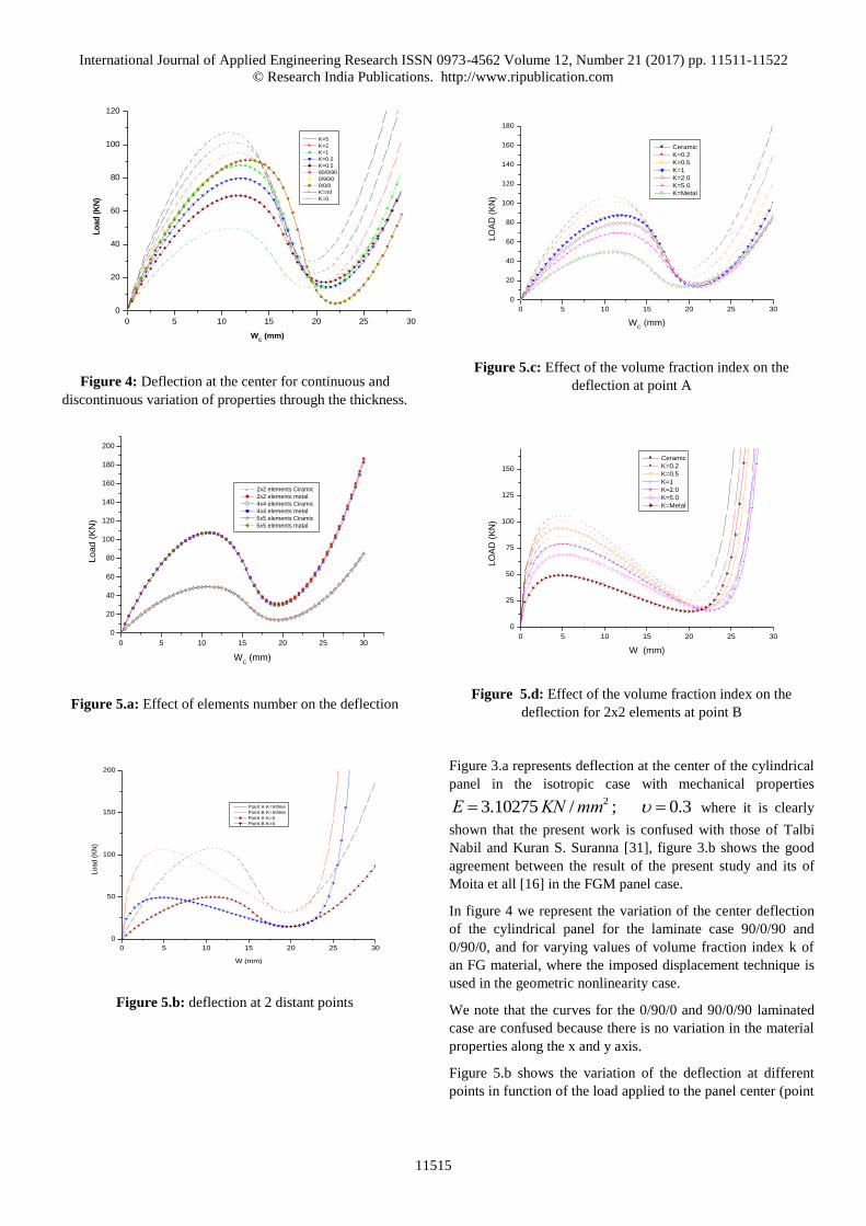
Figure 4: Deflection at the center for continuous and
discontinuous variation of properties through the thickness.
Figure 5.a: Effect of elements number on the deflection
0 5 10 15 20 25 30
0
50
100
150
200
Load (
KN
)
W (mm)
Point A K=Infinie
Point B K=Infinie
Point A K=0
Point B K=0
Figure 5.b: deflection at 2 distant points
0 5 10 15 20 25 30
0
20
40
60
80
100
120
140
160
180
LO
AD
(K
N)
WC (mm)
Ceramic
K=0.2
K=0.5
K=1
K=2.0
K=5.0
K=Metal
Figure 5.c: Effect of the volume fraction index on the
deflection at point A
0 5 10 15 20 25 30
0
25
50
75
100
125
150
LO
AD
(K
N)
W (mm)
Ceramic
K=0.2
K=0.5
K=1
K=2.0
K=5.0
K=Metal
Figure 5.d: Effect of the volume fraction index on the
deflection for 2x2 elements at point B
Figure 3.a represents deflection at the center of the cylindrical
panel in the isotropic case with mechanical properties
3.0;/ 10275.3 2 mmKNE where it is clearly
shown that the present work is confused with those of Talbi
Nabil and Kuran S. Suranna [31], figure 3.b shows the good
agreement between the result of the present study and its of
Moita et all [16] in the FGM panel case.
In figure 4 we represent the variation of the center deflection
of the cylindrical panel for the laminate case 90/0/90 and
0/90/0, and for varying values of volume fraction index k of
an FG material, where the imposed displacement technique is
used in the geometric nonlinearity case.
We note that the curves for the 0/90/0 and 90/0/90 laminated
case are confused because there is no variation in the material
properties along the x and y axis.
Figure 5.b shows the variation of the deflection at different
points in function of the load applied to the panel center (point
0 5 10 15 20 25 30
0
20
40
60
80
100
120
140
160
180
200
Lo
ad
(K
N)
WC (mm)
2x2 elements Ciramic
2x2 elements metal
4x4 elements Ciramic
4x4 elements metal
5x5 elements Ciramic
5x5 elements matal

International Journal of Applied Engineering Research ISSN 0973-4562 Volume 12, Number 21 (2017) pp. 11511-11522
© Research India Publications. http://www.ripublication.com
11516
A), for different values of the volume fraction index k, with a
thickness h = 12.7 mm for the case of an FGM material.
For different discretizations in figure 5.a, we note that the
curves are combined, it is for this reason that we adopt
subsequently the 2X2 mesh elements.
From the curves of Fig.5.c and Fig.5.d can be seen that by
increasing of the volume fraction index k, the limit load
increases. It can be seen also as more as we move away from
the load's application point, the more the deflection decreases
but the limit load remains the same.
0 5 10 15 20 25 30
-10
-5
0
5
10
15
20
25
Lo
ad
(K
N)
WC (mm)
2X2 elements
4X4 elements
5x5 elements
Figure 6.a: effect of elements number on the deflection for
k=5
0 5 10 15 20 25 30
-15
-10
-5
0
5
10
15
20
25
30
35
Lo
ad
(K
N)
WC (mm)
Ceramic
K=0.2
K=0.5
K=1
K=2.0
K=5.0
K=Metal
Figure 6.b: Effect of the volume fraction index on the
deflection for 2x2 elements
0 5 10 15 20 25 30
-15
-10
-5
0
5
10
15
20
25
30
35
Lo
ad
(K
N)
WC (mm)
Ceramic
K=0.2
K=0.5
K=1
K=2.0
K=5.0
K=Metal
Figure 6.c: effect of the volume fraction index on the
deflection for 4x4 elements
0 5 10 15 20 25 30
-15
-10
-5
0
5
10
15
20
25
30
35
Lo
ad
(K
N)
WC (mm)
Ceramic
K=0.2
K=0.5
K=1
K=2.0
K=5.0
K=Metal
Figure 6.d: effect of the volume fraction index on the
deflection for 5x5 elements
0 5 10 15 20 25 30
-15
-10
-5
0
5
10
15
20
25
30
35
Lo
ad
(K
N)
WC (mm)
Ceramic
K=0.2
K=0.5
K=1
K=2.0
K=5.0
Figure 6.e: effect of the volume fraction index on the
deflection using Arc length method.

International Journal of Applied Engineering Research ISSN 0973-4562 Volume 12, Number 21 (2017) pp. 11511-11522
© Research India Publications. http://www.ripublication.com
11517
0 5 10 15 20 25 30
-10
-5
0
5
10
15
20
25
30
Load (
KN
)
WC (mm)
5x5 elements
4x4 elements
2x2 elements
Figure 6.f: effect of the elements number on the deflection for
k=5.
The 50% reduction in thickness, leads to a reduction of 75%
of the limit load which can be seen in Fig.6.a
0 5 10 15 20 25 30
-10
-5
0
5
10
15
20
25
30
Load (
KN
)
WC (mm)
2x2 D.I
2x2 A.I
4x4 A.I
4x4 D.I
5x5 D.I
5x5 A.I
Figure 6.g: effect of the elements number for arc length and
imposed displacement method on the deflection k=5.0
Figure 6.b, 6.c and 6.d represent the variation of the deflection
depending on the load for a thickness h = 6.35 mm, with the
use of the imposed displacement method that do not
accurately reflect the geometrically nonlinear behaviour,
which requires the use of the imposed arc length method
because of the existence of a backspace.
On Fig.6.e and Fig.6.f we represent the deflection depending
on the load for different values of the index of volume fraction
using the imposed arc method which does not represent any
difficulty.
On Fig.6.g we represent the difference between the use of the
imposed displacement method and the imposed arc length
method to better illustrate this numerical difference.
Figure 7.a: variation in the normal stress along y through the
thickness.
Figure 7.b: variation in normal stress along y through the
thickness.
-2.5 -2.0 -1.5 -1.0 -0.5 0.0 0.5 1.0
-1.0
-0.5
0.0
0.5
1.0
Z/2
h
zz
Ceramic
K=0.2
K=0.5
K=1
K=2.0
K=5.0
K=Metal
Figure 7.c: variation in normal stress along z through the
thickness.
-600 -400 -200 0 200 400 600 800
-1,0
-0,5
0,0
0,5
1,0
2Z
/h
xx
Ceramic
K=0.2
K=0.5
K=1
K=2
K=5
Metal
-150 -100 -50 0 50 100 150
-1,0
-0,5
0,0
0,5
1,0
2Z
/h
yy
Ceramic
K=0.2
K=0.5
K=1
K=2
K=5
Metal

International Journal of Applied Engineering Research ISSN 0973-4562 Volume 12, Number 21 (2017) pp. 11511-11522
© Research India Publications. http://www.ripublication.com
11518
-120 -100 -80 -60 -40 -20 0 20 40 60
-1.0
-0.5
0.0
0.5
1.0
Z/2
h
xy
Ceramic
K=0.2
K=0.5
K=1
K=2.0
K=5.0
K=Metal
Figure 7.d: variation in tangential stress along y through the
thickness.
-30 -20 -10 0 10 20 30 40
-1.0
-0.5
0.0
0.5
1.0
Z/2
h
xz
Ceramic
K=0.2
K=0.5
K=1
K=2.0
K=5.0
K=Metal
Figure 7.e: variation in tangential stress along y through the
thickness.
-6 -5 -4 -3 -2 -1 0 1 2
-1.0
-0.5
0.0
0.5
1.0
Z/2
h
yz
Ceramic
K=0.2
K=0.5
K=1
K=2.0
K=5.0
K=Metal
Figure 7.f: variation in tangential stress along y through the
thickness.
Figure 7 shows the variation of normal and tangential stresses
in the direction of thickness for different values of the index k
for volume fraction of a thickness h = 12.7 mm at the end of
the cycle non-linear. Firstly it should be noted that the stress
xzz , and yz as shown in Fig.7.c, Fig.7.e and Fig.7.f are
negligible compared to the other stress which is justified by
the theory of shells used.
In the case of a pure metal or pure ceramic, the normal stress
x and y in Fig 6.a and Fig 6.b are linear and symmetrical,
unlike in the cases where the material is a mixture between the
ceramic and metal.
From the results obtained it can be seen the existence of the
compression in ceramic zone and a traction in the metal fibers.
0 5 10 15 20 25 30
0
20
40
metal
LO
AD
(K
N)
WC (mm)
Pl
GN+Pl
GN
Figure 8.1: effect of elastic plastic on the geometric
nonlinearity for metal.
0 5 10 15 20 25 30
0
20
40
60
80
100
120 ceramic
LO
AD
(K
N)
WC (mm)
Pl
GN+Pl
GN
Figure 8.2: effect of elastic plastic on the geometric
nonlinearity in the case of ceramic.

International Journal of Applied Engineering Research ISSN 0973-4562 Volume 12, Number 21 (2017) pp. 11511-11522
© Research India Publications. http://www.ripublication.com
11519
0 5 10 15 20 25 30
0
10
20
30
40
50
60
70
LO
AD
(K
N)
WC (mm)
ceramic
K=0.2
K=0.5
K=1.0
K=2.0
K=5.0
matal
Figure.8.3: effect of elastic plastic on the geometric
nonlinearity for different values of volume fraction index k.
In Fig 8.1 and Fig 8.2 we represent the load-displacement
curve for the metal and ceramic for geometrically nonlinear
(GN) combined with elastic plastic case (PL).
Fig.8.3, shows the load-displacement curve at the center of
panel according to the volume fraction index, to see the effect
of plasticity on the geometric nonlinearity, and from the result
obtained it is clearly seen that this effect decreases with the
decrease of k factor with the appearance of the limit point.
Nonlinear quadratic shell with concentrated load
In this section the quadratic shell subjected to a concentrated
load as shown in Fig.9. with thickness of 4 mm, all edges are
clamped. The shell is made with two materials for which the
properties used are:
3.0 and Mpa 40 , 70 Y GpaEm
3.0 and Mpa 240, 151 Y GpaEc
Because of the symmetric of the structure, only the quarter is
discritized to 3x3 elements with 9 nodes.
The aim of the analysis is to show the effect of the plasticity
and geometrically nonlinearity on the structure when the
properties change continuously by varying the volume
fraction index from k=0 (pure ceramic case) to k=∞ (pure
metal case).
0 2 4 6 8 10 12 14
0
50
100
150
200
250
LO
AD
(K
N)
WC (mm)
Ceramic
K=0.2
K=0.5
K=1
K=2.0
K=5.0
K=Metal
Figure 10.1: elastic deflection at the center for different
values of volume fraction index k.
0.0 0.1 0.2 0.3 0.4 0.5
0
2
4
6
8
LO
AD
(K
N)
WC (mm)
Ceramic
K=0.2
K=0.5
K=1
K=2.0
K=5.0
K=Metal
Figure 10.2: elastic plastic deflection at the center for
different values of volume fraction index k.
P
L
L
A
D
C B
Y
Z
X
36°
Figure 9: quadratic shell subjected to a
concentrated load

International Journal of Applied Engineering Research ISSN 0973-4562 Volume 12, Number 21 (2017) pp. 11511-11522
© Research India Publications. http://www.ripublication.com
11520
Figure 10.3: elastic and elastic plastic deflection at the center
for the pure metal case.
Figure 10.4: elastic and elastic plastic deflection at the center
for the pure ceramic case.
-12000 -10000 -8000 -6000 -4000 -2000 0 2000 4000 6000 8000
-1.0
-0.5
0.0
0.5
1.0
xx
Ceramic
K=0.2
K=0.5
K=1
K=2.0
K=5.0
K=Metal
Figure 10.5: variation in the normal stress along y through the
thickness.
-12000 -10000 -8000 -6000 -4000 -2000 0 2000 4000 6000 8000
-1.0
-0.5
0.0
0.5
1.0
yy
Ceramic
K=0.2
K=0.5
K=1
K=2.0
K=5.0
K=Metal
Figure 10.6: variation in the normal stress along y through the
thickness.
In Fig 10.1, showing the elastic load-displacement curve, on
which it is noticed that the value of the limit point decrease
with increasing volume fraction index k. So the relationship
limit point is proportional inversely to k and the displacement
is directly proportional to k.
In Fig 10.2, we represent the load-displacement curve in the
elastic and elastic-plastic geometrically nonlinear cases, we
notices the disappearance of the limit point which means that
the elastic-plastic is dominant in this case because the
lamination is reached before the limit point.
In the fig 10.3 and Fig 10.4, a slight difference is noted in the
case of elastic and elastic-plastic case for pure ceramic and
pure metal.
We can also note the figures, Fig 10.5 and Fig 10.6 that
because of the symmetry, the values of the normal stresses on
x and y axis are equal.
These stresses are linear for pure ceramic case and the pure
metal case but are nonlinear when the material is a
composition between them.
In the elastic-plastic case, these stresses are nonlinear even in
the pure metal case or pure ceramic case.
CONCLUSIONS
Linear and nonlinear static behavior of cylindrical shell panel
and quadratic shell with Functionally Graded Material, in
which the material proprieties vary through the thickness,
have been presented for different values of volume fraction
index in the case of a power law. The formulation is based on
the Von Karman field for geometrically nonlinear. The central
deflection, stress are analyzed for the panel and quadratic
shell under a mechanical punctual load at the center.
0,0 0,1 0,2 0,3 0,4 0,5
0,0
0,2
0,4
0,6
0,8
1,0
1,2
1,4
1,6
Metal
LO
AD
(K
N)
WC (mm)
GL
GNL
0,0 0,1 0,2 0,3 0,4 0,5
0
2
4
6
8
10
Ceramic
LO
AD
(K
N)
WC (mm)
GL
GNL

International Journal of Applied Engineering Research ISSN 0973-4562 Volume 12, Number 21 (2017) pp. 11511-11522
© Research India Publications. http://www.ripublication.com
11521
These numerical results show also that it recommended using
the controlled arc length method to give correctly the
nonlinearity behaviour in the case of existence of a snap- back
point.
REFERENCES
[1] Zenkour A.M., 2006. Generalized shear deformation
theory for bending analysis of functionally graded
plates. Applied Mathematical Modeling. Vol. 30, No. 1,
pp. 67-84.
[2] M. Simsek, Static analysis of a functionally graded
beam under a uniformly distributed load by Ritz
method, International Journal of Engineering and
Applied Sciences(IJEAS), Vol.1, Issue 3(2009)1-11.
[3] Chi SH, Chung YL. Mechanical behavior of
functionally graded material plates under transverse
load-Part I: Analysis. Int J Solids Struct 2006;43:3657–
74.
[4] Chi SH, Chung YL. Mechanical behavior of
functionally graded material plates under transverse
load-part II: numerical results. Int J Solids Struct 2006;43:3675–91.
[5] Shen H.-S., 2002. Generalized shear deformation
theory for bending analysis of functionally graded
plates. International Journal of Mechanical Sciences,
Vol. 44, No. 3, pp. 561-584.
[6] Lee K.H., Senthilnathan N.R, Lim S.P, and Chow S.T.,
1989. Nonlinear bending response of functionally
graded plates subjected to transverse loads and in
thermal environments. International Journal of Non-Linear Mechanics. Vol. 24, No. 2, pp. 127-137.
[7] Amin MH, Soleimani M, Rastgoo A. Three-
dimensional free vibration analysis of functionally
graded material plates resting on an elastic foundation.
Smart Mater Struct 2009;18:1–9.
[8] N. Sundararajan, T. Prakash, M. Ganapathi, Nonlinear
free flexural vibrations of functionally graded
rectangular and skew plates under thermal
environments, Finite Elements in Analysis and Design 42 (2005) 152–168.
[9] S. Pradyumna, J.N. Bandyopadhyay, Free vibration
analysis of functionally graded curved panels using a
higher-order finite element formulation, Journal of Sound and Vibration 318 (2008) 176–192.
[10] X.L. Huang, H.-S. Shen, Nonlinear vibration and
dynamic response of functionally graded plates in
thermal environments, International Journal of Solids
and Structures 41 (2004) 2403–2427.
[11] Zenkour A.M., 2005. A comprehensive analysis of
functionally graded sandwich pates: part 1-Deflectiona
and stresses, International Journal of Solids and Structures, Vol. 42, pp. 5224-5242.
[12] Zenkour, A.M.,Sobhy,M.,2010.Thermal buckling of
various types of FGM sandwich
plates.Compos.Struct.93,93–102.
[13] Zenkour, A.M.,Alghamdi, N.A.,2010.Bending analysis
of functionally graded sandwich plates under the effect
of mechanical and thermal loads. Mech.Adv.Mater. Struct.17,419–432.
[14] Zhen-Xin Wang, Hui-ShenShen, Non linear dynamic
response of sandwich plates with FGM face sheets
resting on elastic foundations in thermal environments,
Ocean Engineering 57 (2013) 99–110
[15] J.S. Park, J.H. Kim, Thermal postbuckling and
vibration analyses of functionally graded plates,
Journal of Sound and Vibration 289 (2006) 77–93.
[16] J.S. Moita, A.L. Araujo, C.M Mota Soares, C.A. Mota
Souares, J. Herskovits, Material and Geometric
Nonlinear Analysis of Functionally Graded Plate-Shell
Type Structures, (2016), Appl Compos Mater.
[17] J. Suresh Kumar1, B. Sidda Reddy2,*, C. Eswara
Reddy3, K. Vijaya Kumar Reddy4, "Geometrically non
linear analysis of functionally graded material plates
using higher order theory", International Journal of Engineering, Science and Technology, Vol. 3, No. 1,
2011, pp. 279-288
[18] A.H. Sofiyev *, The vibration and stability behavior of
freely supported FGM conical shells subjected to
external pressure, Composite Structures 89 (2009) 356–
366.
[19] Mohammad Talha, B.N.Singh, "Large amplitude free
flexural vibration analysis of shear deformable FGM
plates using non linear finite element method", Finite element in analysis and design, 47 pp.394-401, 2011.
[20] S.C. Pradhan, "Vibration suppression of FGM shells
using embedded magnetostrictive layerss",
International Journal of Solids and Structures 42 (2005) 2465–2488.
[21] A.K. Upadhyay, K.K. Shukla, "Geometrically
nonlinear static and dynamic analysis of functionally
graded skew plates", Commun Nonlinear Sci Numer
Simulat, 2013.
[22] Kanok-Nukulchai W., "A simple and efficient finite
element for general shell analysis" Int. Journal. For. Num. methods. Engng, 14, pp. 179-200, 1979.
[23] Djermane M., Chelghoum A., Amieur B. and Labbaci
B., "The linear and nonlinear thin shell analysis using a
mix finite element with drilling degrees of freedom" ,
Int. J. Appl. Eng, pp 217-236, 2006.
International Journal of Applied Engineering Research ISSN 0973-4562 Volume 12, Number 21 (2017) pp. 11511-11522
© Research India Publications. http://www.ripublication.com
11522
[24] Djermane M., "Analyse des coques minces par la
méthode des éléments finis utilisation d'un élément
tortionnel" ,Master thesis USTHB Alger, 1991.
[25] Djermane M., Chelghoum A., Amieur B. and Labbaci
B., "Nonlinear Dynamic Analysis of Thin Shells Using
a Finite Element With Drilling Degrees of Freedom" ,
Int. J. Appl. Eng, pp 97-108, 2007.
[26] Huang. H.C and Hinton.E, " A New nine nodes
degenerated shell element with enhanced membrane
and shear interpolation", Int. Journal for numerical methods Eng; 22, pp.73-92, 1986.
[27] H.T.Y.Yang, S.Saigal and D.G.Liaw. "Advances of
thin shell finite elements and some applications –
version I ", computer $ structures, vol 35 (4) pp.481-
504, 1990
[28] Reddy, J. N., "Gemetrically non-linear transient
analysis of laminated composite plates." AIAA Jnl, 42,
pp.621-629, 1983.
[29] S.Swaddiwudhipony and Z.S.Liu: "Dynamic response
of large strain elasto-plastic plate and shell structures",
Thin- Walled structures, vol 26 (4) 223-239, 1996.
[30] Alireza Beheshti, Shojaa Ramezani, Nonlinear element
analysis of functionally graded structures by enhanced
assumed strain shell elements, Applied Mathematical
Modelling, (2014).
[31] B. Amieur, M. Djermane, Analyse du comportement
des coques géométriquement linéaire et non linéaire
Par la méthode des elements finis utilisation d’un
élément à champs de déformations augmenté, (2011),
Journal of Science Research N 2, Vol. 1, p3-8,Université de Béchar
[32] X. Zhao, K.M. Liew, Geometrically nonlinear analysis
of functionally graded shells (2009) Int J Mech Sci, 51,
pp. 131-144