nonlinear model of the vehicle hydropneumatic suspension...
TRANSCRIPT

Number 4, Volume VII, December 2012
Kupka: Nonlinear Model of the vehicle hydropneumatic Suspension Unit 79
NONLINEAR MODEL OF THE VEHICLE HYDROPNEUMATIC SUSPENSION UNIT
Libor Kupka1
Summary: The lumped parameters model of the hydropneumatic suspension unit and its verification is described in the paper. The relations effective surface and volume of the rubber bellows air spring versus position and pressure and Bernoulli equation are used in the mathematical model of hydraulic part. The oil volume compression changes are considered negligible. The adiabatic state equation for the gas is used. The gas flow through the throttling injector is considered both in under and over-critical conditions. The static and dynamic characteristics of the whole unit and its parts were measured.
Key words: hydropneumatic suspension unit, rubber bellows air spring, mathematical model.
INTRODUCTION
The hydropneumatic suspension unit (fig. 1) consists of hydraulic and pneumatic parts. It is possible to separate the hydraulic part for the measurement (1, 2).
Source: Author
Fig. 1 – Hydropneumatic suspension unit
1 Ing. Libor Kupka, Ph.D., University of Pardubice, Faculty of Electrical Engineering and Informatics, Department of Process Control, náměstí Čs. legií 565, 532 10 Pardubice, Tel.: +420 466 037 504, Fax: +420 466 036 241, E-mail: [email protected]

Number 4, Volume VII, December 2012
Kupka: Nonlinear Model of the vehicle hydropneumatic Suspension Unit 80
The unit (see fig. 1) consists of: pneumatic rubber bellows air spring (1), steel chamber (2), pneumatic actuator and channels (3, 4 and 5), lower and upper rubber bellows spring (6 and 7, silicon oil filled), fixed channel (8), hydraulic actuator and channels (9, 10), steel rod (11) and lateral guidance system of upper rubber bellows spring (12).
1. NONLINEAR MATHEMATICAL MODEL
1.1 Hydraulic part The hydraulic part has the character of a classic damper, but it has small spring
character as well. Hydraulic part consists of two rubber bellows springs, which are connected with each other through a throttling bore and parallel hydraulic channels with actuator.
Source: Author
Fig. 2 – Scheme of the hydraulic part of the unit (1, 2 – lower and upper rubber bellows springs, 3 – fixed point of measurement equipment, 4 – throttling bore, 5 – servo valve)
The relations between position and pressure of one rubber bellows spring and the
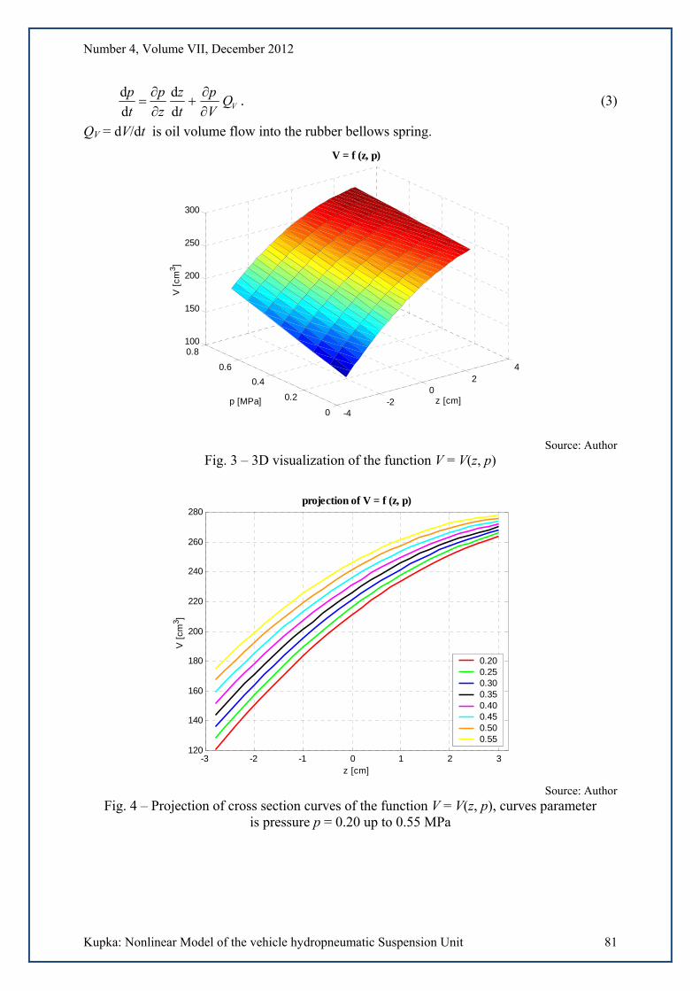
effective surface were measured using laboratory purpose-built testing equipment. The relation volume versus position and pressure was approximated with function (1).
The volume approximation function was chosen in the following form
pzapaeazaapzV VVza
VVVV
542103),( , (1)
where V is volume, z is position, p is pressure, aV0 up to aV5 are coefficients. The coefficients aV4 and aV5 were determined experimentally from the measurement on
the assembled hydraulic part. The explicit expression p = p(z, V) from (1) is
zaa
eazaaVp
VV
zaVVV
V
54
2103
. (2)
The pressure inside e.g. lower rubber bellows spring as a function of time is described by
Number 4, Volume VII, December 2012
Kupka: Nonlinear Model of the vehicle hydropneumatic Suspension Unit 81
VQV
p
t
z
z
p
t
p
d
d
d
d. (3)
QV = dV/dt is oil volume flow into the rubber bellows spring.
-4-2
02
4
0
0.2
0.4
0.6
0.8100
150
200
250
300
z [cm]
V = f (z, p)
p [MPa]
V [
cm3 ]
Source: Author
Fig. 3 – 3D visualization of the function V = V(z, p)
-3 -2 -1 0 1 2 3120
140
160
180
200
220
240
260
280
z [cm]
V [
cm3 ]
projection of V = f (z, p)
0.200.250.300.350.400.450.500.55
Source: Author
Fig. 4 – Projection of cross section curves of the function V = V(z, p), curves parameter is pressure p = 0.20 up to 0.55 MPa

Number 4, Volume VII, December 2012
Kupka: Nonlinear Model of the vehicle hydropneumatic Suspension Unit 82
Let us compute the derivatives p/z and p/V from (2) and substitute them into (3)
zaa
Q
t
z
zaa
azeazaaVzaaeaaa
t
p
VV
V
VV
Vza
VVVVVza
VVVVV
542
54
521054321
d
d
)(
)())((
d
d 33
(4)
Let us designate the pressures inside the lower and the upper bellows and difference
between them p1, p3 and p = p3 – p1 respectively. The following approximation of the
solution of Bernoulli's equation was used to compute QV
h
he1)(sign
RpQ
p
V
, (5)
Rh is a hydraulic resistance and h is coefficient which affects the derivative dQV /d(p) for
p = 0.
The force
11hef33hef13h pSpSFFF , (6)
Shef1 and Shef3 are effective surfaces of the upper and lower bellows springs. The approximation of the effective surface of bellows spring was chosen in the following form
pzapaeazaapzS SSza
SSSS
54210hef3),( . (7)
Source: Author
Fig. 5 – 3D visualization of the approximation Shef = Shef(z, p) and measurements of an effective surface
1.2 Pneumatic part The pneumatic part of the suspension unit consists of rubber bellows springs, steel
chamber and actuator – throttling element (see fig. 6). The equation of adiabatic changes in air is
konstp , (8)
where p is pressure, is density and =1.4. The differential form of (8) is

Number 4, Volume VII, December 2012
Kupka: Nonlinear Model of the vehicle hydropneumatic Suspension Unit 83
0d
d
d
d 1
tp
t
p . (9)
From (9)
t
p
t
p
d
d
d
d 2
2
22
(10)
and
t
p
t
p
d
d
d
d 4
4
44
. (11)
Mass conservation law is
konstVm (12)
and the differential form of this law is
md
d
d
d
d
dQ
t
VV
tt
m
, (13)
Qm is mass flow.
Source: Author
Fig. 6 – Scheme of the pneumatic part of the unit (1 – bellows air spring, 2 – steel chamber, 3 – fixed point of measurement equipment, 4 – throttling injector, loss coefficient PT,
5 – servo valve, loss coefficient PS)

Number 4, Volume VII, December 2012
Kupka: Nonlinear Model of the vehicle hydropneumatic Suspension Unit 84
The modifications of equation (13) for both parts of pneumatic unit are
m12
2122
d
d
d
d)(
d
dQ
t
V
t
VVV
t
(14)
and
m3
4344
d
d)(
d
dQ
t
VVV
t
. (15)
From (14) and (15)
t
V
t
VQ
VVt d
d
d
d1
d
d 122m
12
2 , (16)
respectively
t
VQ
VVt d
d1
d
d 34m
34
4 . (17)
Bernoulli equation is used for the adiabatic gas flow through the throttling injector
konstpvpv
2i
2i22i
1i
1i21i
1212
, (18)
pi1, vi1, i1 and pi2, vi2, i2 are variables, which describe the flow in front of and behind the
throttling injector. Since vi1 << vi2, the relation between flow velocities is
1
1i
2i
1i
1i2i 1
1
2
p
ppv . (19)
For pi1, i1 and pi2, i2 from (8)
1i
1
1i
2i2i
p
p . (20)
The mass flow through the throttling injector is
2i2im vSQ , (21)
S is the sectional area of the throttling injector. After substitution of (19) and (20) into (21) and using the loss coefficient is
1
1i
2i
2
1i
2i1i1im 1
2
p
p
p
ppSQ . (22)
This equation is valid for under-critical (laminar) flow, in the case of air it means for
pi2/pi1 0.528. Let us designate pkrit/pi1 = 0.528. For over-critical (turbulent) flow, for
pi2/pi1 < 0.528 is
1
1i
krit
2
1i
krit1i1im 1
2
p
p
p
ppSQ . (23)

Number 4, Volume VII, December 2012
Kupka: Nonlinear Model of the vehicle hydropneumatic Suspension Unit 85
The resulting force is
GFFFF 321 . (23)
The force F2 of the rubber bellows air spring (fig. 7) is
2pef2 pSF . (24)
The dependences of effective surface Spef and volume V2 on position (see fig. 8) were approximated with fifth degrees polynomials.
Source: Author
Fig. 7 – Scheme of the rubber bellows air spring Rubena VD 135-07
-6 -4 -2 0 2 4 640
60
80
100
120
140
160
180
200
220
z [cm]
Sef
[cm
2 ]
Sef
= f(z), V = f(z)
1400
1600
1800
2000
2200
2400
2600
2800
V [
cm3 ]
Sef
(z)
V(z)
Source: Author
Fig. 8 – Effective surface and volume of the used bellows spring Rubena VD 135-07 (Spef Sef and V2 V)

Number 4, Volume VII, December 2012
Kupka: Nonlinear Model of the vehicle hydropneumatic Suspension Unit 86
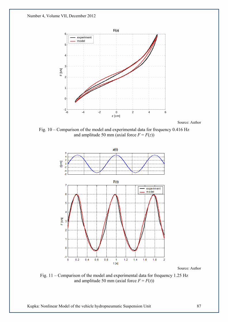
2. SIMULATION
The simulation model was created in MATLAB – Simulink. Plots of an axial force F(z) acquired by numerical simulation are in figs. 9 up to 14, the frequencies of the harmonic signal were 0.416, 1.25 and 3.5 Hz, the amplitudes were 50, 50 and 30 mm.
Source: Author
Fig. 9 – Comparison of the model and experimental data for frequency 0.416 Hz and amplitude 50 mm (axial force F = F(t))
Number 4, Volume VII, December 2012
Kupka: Nonlinear Model of the vehicle hydropneumatic Suspension Unit 87
-6 -4 -2 0 2 4 6-1
0
1
2
3
4
5
6
z [cm]
F [
kN]
F(z)
experimentmodel
Source: Author
Fig. 10 – Comparison of the model and experimental data for frequency 0.416 Hz and amplitude 50 mm (axial force F = F(z))
Source: Author
Fig. 11 – Comparison of the model and experimental data for frequency 1.25 Hz and amplitude 50 mm (axial force F = F(t))

Number 4, Volume VII, December 2012
Kupka: Nonlinear Model of the vehicle hydropneumatic Suspension Unit 88
-6 -4 -2 0 2 4 6-1
0
1
2
3
4
5
6
7
z [cm]
F [
kN]
F(z)
experimentmodel
Source: Author
Fig. 12 – Comparison of the model and experimental data for frequency 1.25 Hz and amplitude 50 mm (axial force F = F(z))
Source: Author
Fig. 13 – Comparison of the model and experimental data for frequency 3.5 Hz and amplitude 30 mm (axial force F = F(t))

Number 4, Volume VII, December 2012
Kupka: Nonlinear Model of the vehicle hydropneumatic Suspension Unit 89
-3 -2 -1 0 1 2 30
1
2
3
4
5
6
z [cm]
F [kN
]
F(z)
experimentmodel
Source: Author
Fig. 14 – Comparison of the model and experimental data for frequency 3.5 Hz and amplitude 30 mm (axial force F = F(z))
CONSLUSIONS
The development of a hydropneumatic suspension unit (with rubber bellows springs) is described in the paper. The simulation model was created in MATLAB – Simulink. This model matches the dynamics of the hydropneumatic unit under consideration relatively well. Prospective application of this unit is truck back axle suspension. The spring and damping characteristics can be changed in the case of semi-active, or active control. The control has not been designed yet.
ACKNOWLEDGMENT
The work has been supported by the funds No. SGFEI03/2012 of the University of Pardubice, Czech Republic. This support is very gratefully acknowledged.
REFERENCES
(1) ŠKLÍBA, J.; BARBORA, J.; CIRKL, D. Hydropneumatický člen s paralelním řazením hydraulického a pneumatického tlumení. In Proceedings of Interaction and Feedbacks 2000. Prague: Institute of Thermomechanics AS CR, 2000. pp. 233 – 236. ISBN 80-85918-58-7.
(2) BARBORA, J.; JANEČEK, B.; KUPKA, L.; ZŮBEK, T. Hydropneumatic Suspension Rubber-bellows Unit. In Proceedings of Colloquium Euromech 455 on Semi-Active Vibration Suppression [CD–ROM]. Prague: CTU, 2004. 13 p.
(3) BAUER, W. Hydropneumatic Suspensions Systems. 1st ed. Berlin – Heidelberg – New York: Springer, 2011. ISBN 978-3-642-15146-0.

Number 4, Volume VII, December 2012
Kupka: Nonlinear Model of the vehicle hydropneumatic Suspension Unit 90
(4) HANUŠ, B.; OLEHLA, M.; MODRLÁK, O. Číslicová regulace technologických procesů: algoritmy, matematicko-fyzikální analýza, identifikace, adaptace. Brno: BUT, 2000. ISBN 80-214-1460-X.
(5) VESTFÁLOVÁ, M.; STŘEDA, I. Technická dynamika plynů. Liberec: TU, 2004.
(6) KUPKA L.: Vyhodnocení průběhů průtokových charakteristik elektropneumatického servoventilu VEF 312 1–2. [Research report.] Liberec: TU, 2005.