novel quadcopter flight controller and telemetry...
TRANSCRIPT
Novel Quadcopter Flight
Controller and
Telemetry Remote
2015
ENG470 ENGINEERING THESIS AHARON CUNTA
SUPERVISOR | Dr David Parlevliet

Page | 1
This page has been left intentionally blank.

Page | 2
Acknowledgements
Firstly, I would like to acknowledge and thank my supervisor Dr David Parlevliet for his guidance and
enthusiasm throughout the course of this project. No different from my first year physics unit with
David, his motivating chats were truly inspiring.
Secondly, to my brother Avrahan Cunta; I really appreciate the time you took to help build the test
frame. Without it, the initial testing would not have gone so smoothly.
Finally, my most heart filled gratitude goes to Agi and Scott Thompson. I could not have got this far
without your endless encouragement and support.
Page | 3
Abstract
This project designed, constructed and implemented a novel quadcopter flight controller and
remote.
With the quadcopters’ popularity ever increasing, more people are making use of the advantages
this machine can offer. From surf photographers to hobbyists, the quadcopter needs to be easy to
setup, tune and relay information back to the operator to ensure safe flight. A functionality not
found on today’s market.
Components were chosen, tested and implemented to create a functioning quadcopter flight
controller and remote system.
Although the implementation is regarded as being successful, there are still some design changes
that could improve the functionality of the system. Noise from altitude readings hampered the
altitude hold functionality and as well as no method implemented to counter for the change in
barometric pressure throughout the day. But with efficient code making use of hardware the
hardware, there is still sufficient computational time left to implement signal filtering simply not
available at the lower market end of commercial flight controllers. An additional $10 barometer
could also solve the altitude creep as ground barometric pressure changes.

Page | 4
1 Table of Contents
Acknowledgements ................................................................................................................................. 2
Abstract ................................................................................................................................................... 3
List of Figures .......................................................................................................................................... 7
List of Tables ........................................................................................................................................... 9
Glossary of Abbreviations ..................................................................................................................... 10
2 Introduction .............................................................................................................................. 11
2.1 Project Objective ................................................................................................................... 12
3 Background ............................................................................................................................... 13
3.1 Drone History ........................................................................................................................ 13
3.2 Drone Laws ............................................................................................................................ 15
3.2.1 Rules of Operation ........................................................................................................ 15
3.3 Drone Crashes ....................................................................................................................... 16
3.4 Power Source ........................................................................................................................ 18
3.5 Quadcopter Control Algorithms ............................................................................................ 19
3.5.1 PID Controller ................................................................................................................ 19
3.5.2 Control Algorithms ........................................................................................................ 20
3.5.3 PID Controller Applied to Hexacopter Flight ................................................................. 21
3.5.4 MPC and Adaptive Back Stepping ................................................................................. 22
3.5.5 Modelling and Control .................................................................................................. 23
3.6 Quadcopter Build Options .................................................................................................... 24
3.6.1 Enthusiast: Sturdy Quadcopter Build ............................................................................ 24
3.6.2 Professional: Walkera – Voyager3 GoPro ..................................................................... 25
3.6.3 Walkera – QRX900 ........................................................................................................ 26
3.6.4 Walkera – Scout X4 ....................................................................................................... 27
3.6.5 Parrot – AR Drone 2.0 ................................................................................................... 28
3.6.6 Parrot – eXom ............................................................................................................... 29
3.7 Market Recap ........................................................................................................................ 30
4 Quadcopter Physical Structure ................................................................................................. 31
4.1 Frame .................................................................................................................................... 32
4.2 Electronic Speed Controller .................................................................................................. 33
4.3 Synchronous Brushless Motor .............................................................................................. 34
4.4 Propeller ................................................................................................................................ 35
4.5 Battery ................................................................................................................................... 36
4.6 Expected Weight of System .................................................................................................. 37
5 Software .................................................................................................................................... 38
5.1 Integrated Development Environment (IDE) ........................................................................ 38
Page | 5
5.1.1 Atmel Studio 6.2 ............................................................................................................ 38
5.1.2 Atmel Software Framework .......................................................................................... 38
5.2 C/C++ Language .................................................................................................................... 38
5.3 Protocols ............................................................................................................................... 39
5.3.1 SPI .................................................................................................................................. 39
5.3.2 I2C ................................................................................................................................. 39
5.3.3 UART .............................................................................................................................. 39
5.3.4 NMEA 0183 ................................................................................................................... 40
5.3.5 IEEE 802.15.4 ................................................................................................................. 40
6 Electrical Components .............................................................................................................. 41
6.1 Arduino Platform .................................................................................................................. 41
6.1.1 Arduino Due .................................................................................................................. 41
6.1.2 Atmel SAM3X8E ............................................................................................................ 44
6.2 IMU........................................................................................................................................ 44
6.3 Bosch BMP180 ...................................................................................................................... 47
6.4 Ublox NEO 6M GPS ............................................................................................................... 48
6.5 Xbee Pro S1 ........................................................................................................................... 49
6.6 3-Axis Joystick ....................................................................................................................... 50
6.7 LCD Screen ............................................................................................................................ 52
6.8 SD Card Interface .................................................................................................................. 52
6.9 Voltage Measurement .......................................................................................................... 52
7 Design Strategy ......................................................................................................................... 53
7.1 Pseudo Scheduler System ..................................................................................................... 53
7.2 Radio Communications Packet Structure ............................................................................. 54
7.3 PID Control ............................................................................................................................ 55
7.4 Motor Mixing ........................................................................................................................ 55
7.5 Telemetry .............................................................................................................................. 56
7.6 Logging .................................................................................................................................. 57
8 Component Implementation .................................................................................................... 58
8.1 Atmel SAM3X8E Specific Configuration ................................................................................ 58
8.1.1 Waveform Mode ........................................................................................................... 58
8.1.2 Timer Counter ............................................................................................................... 61
8.2 Pseudo Scheduler Framework .............................................................................................. 63
8.3 Inertial Measurement Unit ................................................................................................... 63
8.3.1 Setup ............................................................................................................................. 64
8.3.2 Reading Data ................................................................................................................. 65
8.4 Global Positioning System ..................................................................................................... 66
8.4.1 Setup ............................................................................................................................. 66
Page | 6
8.4.2 Reading Data ................................................................................................................. 68
8.5 Barometer ............................................................................................................................. 69
8.5.1 Setup ............................................................................................................................. 69
8.5.2 Reading Data ................................................................................................................. 71
8.6 Wireless Communications .................................................................................................... 72
8.6.1 Setup ............................................................................................................................. 73
8.6.2 Reading and Sending Data ............................................................................................ 74
8.7 Joystick .................................................................................................................................. 75
8.7.1 Reading Data ................................................................................................................. 75
8.8 Display ................................................................................................................................... 76
8.9 Voltage Divider ...................................................................................................................... 77
8.10 SD Card Module .................................................................................................................... 77
9 Program Flow ............................................................................................................................ 81
9.1 Remote .................................................................................................................................. 81
9.2 Quadcopter ........................................................................................................................... 81
10 Analysis ..................................................................................................................................... 83
10.1 Altitude Hold ......................................................................................................................... 83
10.2 Altitude Restriction ............................................................................................................... 83
10.3 Altitude over 16 minutes ...................................................................................................... 84
10.4 Pseudo Scheduler .................................................................................................................. 85
10.5 Battery Monitoring ............................................................................................................... 86
10.6 Battery Voltage during Fight ................................................................................................. 87
11 Discussion .................................................................................................................................. 88
12 Recommendations and Future Improvements ......................................................................... 91
13 Conclusion ................................................................................................................................. 92
14 Appendix 4 – Copyright Permission .......................................................................................... 93
15 Bibliography .............................................................................................................................. 96
Page | 7
List of Figures
Figure 1 - Quadcopter Crash 1 [5] ......................................................................................................... 17 Figure 2 - Quadcopter Crash 2 [8] ......................................................................................................... 17 Figure 3 - PID Diagram [13] ................................................................................................................... 20 Figure 4 - Euler Angle Example [15] ...................................................................................................... 21 Figure 5 – Quadcopter Chassis .............................................................................................................. 32 Figure 6 – Afro 30A ESC ......................................................................................................................... 33 Figure 7 – NTM 2826s Brushless Motor ................................................................................................ 34 Figure 8 - HobbyKing 9x4.7 Propeller ................................................................................................... 35 Figure 9 - Zippy 5Ah Li-Po Battery ......................................................................................................... 37 Figure 10 – SPI Data Direction Illustration ............................................................................................ 39 Figure 11 - Arduino Due ........................................................................................................................ 41 Figure 12 – Arduino Due Buck Converter ............................................................................................. 42 Figure 13 – Texus Instruments LM2734 Load Current verses Efficiency .............................................. 42 Figure 14 – Adafruit BNO055 Board Schematic [43] ............................................................................. 46 Figure 15 – Adafruit Board with Bosch BNO055 ................................................................................... 46 Figure 16 - ublox NEO 6M GPS Module ................................................................................................ 48 Figure 17 – Xbee Pro S1 ........................................................................................................................ 50 Figure 18 – Omter OM300B Top ........................................................................................................... 51 Figure 19 - Omter OM300B Return to Centre Mechanism ................................................................... 51 Figure 20 - SD Card Module .................................................................................................................. 52 Figure 21 - Design Process of Project .................................................................................................... 53 Figure 22 – Pseudo Scheduler Example ................................................................................................ 54 Figure 23 - Remote Packet Construction .............................................................................................. 55 Figure 24 - Telemetry Packet Construction .......................................................................................... 55 Figure 25 - Motor Labels and Direction ................................................................................................ 56 Figure 26 - Potential Telemetry Screen ................................................................................................ 57 Figure 27 - Waveform Mode Example .................................................................................................. 58 Figure 28 - Arduino Due Pinout Diagram [38] ....................................................................................... 60 Figure 29 - Peripheral I/O to Arduino Due Pinout ................................................................................ 60 Figure 30 - Waveform Mode Configuration .......................................................................................... 61 Figure 31 - Interrupt Setup on TC1, Channel 0 ..................................................................................... 62 Figure 32 - Function - Interrupt Service Routine .................................................................................. 62 Figure 33 - Pseudo Scheduler Code ...................................................................................................... 63 Figure 34 - Check I2C Device - Code ...................................................................................................... 64 Figure 35 - BNO055 Operation Mode Register ..................................................................................... 64 Figure 36 - BNO055 Operation Mode Fusion Options [42] ................................................................... 65 Figure 37 - BNO055 Read Data Code .................................................................................................... 65 Figure 38 - BNO055 Euler Values Registers .......................................................................................... 66 Figure 39 - U-Centre 8.18 Baud Configuration [48] .............................................................................. 67 Figure 40 - NMEA Example String ......................................................................................................... 68 Figure 41 - BMP180 Read Calibration Data Code ................................................................................. 70 Figure 42 - XBee connected to Freetronics USB-UART ......................................................................... 73 Figure 43 - Function readXbee() ........................................................................................................... 74 Figure 44 - Converting ASCII to Hex to Decimal – part1 ....................................................................... 75 Figure 45 - Converting ASCII to Hex to Decimal - part2 ........................................................................ 75 Figure 46 - Function - Read ADC ........................................................................................................... 76 Figure 47 - Remote Screen .................................................................................................................... 76 Figure 48 - SD Card Read PID Values ..................................................................................................... 78 Figure 49 - Create New Log File Code ................................................................................................... 79
Page | 8
Figure 50 - Logging Data to SD Card Code ............................................................................................ 80 Figure 51 - Remote: programOne() ....................................................................................................... 81 Figure 52 - Remote: programTwo() ...................................................................................................... 81 Figure 53 - Quadcopter : programOne() ............................................................................................... 82 Figure 54 - Quadcopter: programTwo() ................................................................................................ 82 Figure 55 - Altitude Hold Test ............................................................................................................... 83 Figure 56 - Altitude Height Restriction ................................................................................................. 84 Figure 57 - Altitude Log ......................................................................................................................... 84 Figure 58 - Barometric Pressure During Test [59] ................................................................................. 85 Figure 59 - Pseudo Scheduler Performance .......................................................................................... 86 Figure 60 - Battery Voltage Comparison ............................................................................................... 87 Figure 61 - Battery Voltage during Throttle .......................................................................................... 87
Page | 9
List of Tables
Table 1 - Voyager3 GoPro Specifications .............................................................................................. 26 Table 2 - QRX900 Specifications ............................................................................................................ 27 Table 3 - Scout X4 .................................................................................................................................. 28 Table 4 - Frame Specifications .............................................................................................................. 32 Table 5 - ESC Specifications ................................................................................................................... 33 Table 6 - NTM 2826s Specifications ...................................................................................................... 35 Table 7 - Propeller Specifications .......................................................................................................... 36 Table 8 - Battery Comparison ............................................................................................................... 36 Table 9 - Chassis Weight ....................................................................................................................... 37 Table 10 - Arduino Price Comparison ................................................................................................... 41 Table 11 - Arduino Due Peripherals ...................................................................................................... 43 Table 12 - Arduino Due Specifications .................................................................................................. 43 Table 13 - IMU Available Options [43] [44] [45] ................................................................................... 45 Table 14 – Barometer Available Options .............................................................................................. 47 Table 15 - Available GPS Options .......................................................................................................... 48 Table 16 - Wireless Communication Options ....................................................................................... 49 Table 17 - Motor Mixing Matrix ............................................................................................................ 56 Table 18 - SAM3X8E Timer Instance to I/O ........................................................................................... 59 Table 19 - NMEA GPGGA Sentence Structure ....................................................................................... 66 Table 20 - BMP180 Calibration Coefficients ......................................................................................... 69 Table 21 - XBee Modified Settings ........................................................................................................ 73
Page | 10
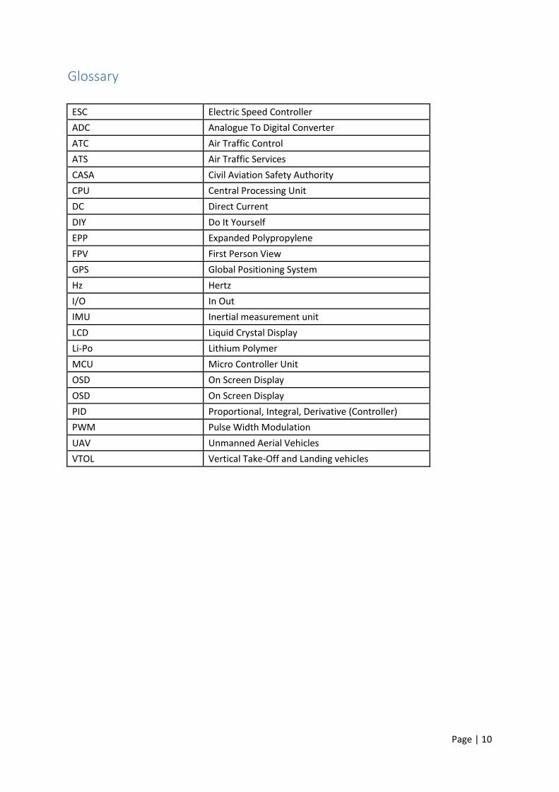
Glossary
ESC Electric Speed Controller
ADC Analogue To Digital Converter
ATC Air Traffic Control
ATS Air Traffic Services
CASA Civil Aviation Safety Authority
CPU Central Processing Unit
DC Direct Current
DIY Do It Yourself
EPP Expanded Polypropylene
FPV First Person View
GPS Global Positioning System
Hz Hertz
I/O In Out
IMU Inertial measurement unit
LCD Liquid Crystal Display
Li-Po Lithium Polymer
MCU Micro Controller Unit
OSD On Screen Display
OSD On Screen Display
PID Proportional, Integral, Derivative (Controller)
PWM Pulse Width Modulation
UAV Unmanned Aerial Vehicles
VTOL Vertical Take-Off and Landing vehicles
Page | 11
2 Introduction
The quadcopter has increased in popularity and it is part of our future. They are marketed from
mere toys to commercial forms of transport to a sport akin to motor racing. With the cost of
electronics and sensors reducing and the capabilities of these devices increasing, more uses and
applications for the quadcopter are on the horizon.
Quadcopters, as the name suggests, have four rotors which accelerate the air adjacent to the
quadcopters frame where an equal but opposite force is exerted, generating lift. This property
allows the machine to take-off and land vertically making the quadcopter a versatile tool which can
operate in many environments. By manipulating how much thrust each rotor produces the
quadcopter can rotate about one or two axes and the direction of flight can be then altered. Being
unstable by design, the quadcopter requires a level of autonomy to maintain flight. This device is
the flight controller.
The components used and their implementation have been extensively researched and tested in
both lab and real-world environments. This document is intended to provide sufficient insight into
the design and implementation of a novel flight controller and remote system.
[1]
Page | 12
2.1 Project Objective
The aim of this thesis is to design, construct and implement a novel quadcopter flight controller
which can be quickly implemented on any ‘X’ frame quadcopter. The system will be combined with a
remote control, enabling flight control settings to be seamlessly modified in the field without the aid
of a computer. Moreover, basic functions found in expensive, commercial systems such as data
logging, retrieval of previous flight settings, altitude hold and restrictions (in accordance with the
Civil Aviation Safety Authority (CASA)) will be included.
The system is intended for an end user, who would attach varying loads to a range of quadcopter
frames and operate in different weather conditions. For example, surf photographers filming with
the aid of a quadcopter mounted camera, will benefit from the ability to modify flight control
settings in the field to quickly counter ever varying weather conditions, camera combinations and
even entire quadcopter frames.
Page | 13
3 Background
This section will briefly introduce some background information to quadcopters.
3.1 Drone History
Quadcopters developed from drones which belong to a class called UAVs and are therefore simply
flying robots with software controlled flight plans programmed into their system. Quadcopters are
newer than UAVs and use GPS to track and guide each movement. They depend on four spinning
blades of which two spin clock-wise and two spin counter-clockwise supplying thrust [1]. The pilot
can change the speed of the rotors by sending a signal to the quadcopter using a remote controlled
transmitter [2] [1].
Drones were first developed by the Austrian military using the devices for combat purposes, after
previously using hot air balloon to attack Venice, Italy in 1849 [1]. The first unmanned planes first
appeared after World War 1 and were developed by Elmer Sperry of the Sperry Gyroscope company
[1]. Not long after, the American military turned these planes into drones, one of them being called
‘Larynx’. It could be launched from a warship and fly on autopilot [1].
Reginald Denny formed Reginal Denny Industries, which designed the first mass-produced airplane
and later, the radio plane that was mass produced for World War 2 and could collect radio-active
data [1].
Quadcopters were then engineered in order to take away some of the difficulties that pilots were
experiencing with vertical flight in helicopters. The first model was called ‘Oehmichen2’ after Etienne
Oehmichen who invented the device in 1920 [1] [2]. It flew 1000 times and its longest flight was
360metres, a world record [2].
The first air craft to use propulsion for its pitch and yaw controls, was the Convertawings Model A
quadcopter, which was designed by Dr. George E. Bothezat in 1956. It was followed by the Curtis
Wright V7 not long after, in 1958 [1].

Page | 14
Since then the technology has improved quadcopters radically. Companies like Parrot, DJ
Innovations and Heli-Max have released quadcopters using advanced computer technology for aerial
photography and flight control [1].
Some of the quadcopter’s advantages consist of blending features from co-axial and pitched
helicopters. Pitched helicopters are agile and wind resistant, whereas co-axial helicopters are more
stable due to the two layers of rotors. In combination with these two features, quadcopters also
make use of three axis gyro-technology, which further stabilizes the device [1].
Since a quadcopter’s centre of gravity is in the middle of the motors, the device is easy to balance.
[2].
All these facts give quadcopters a wide range of possible applications and can therefore be used in
different field. Their applications range from gathering information for flight control and real-time
system research their uncovering criminal activity such as finding drug trafficking rings in Central
America. Their popularity stems from their inexpensive build, as well as their ability to access
difficult areas via air which could be impossible to navigate for human beings [1].
Next to their aiding scientists and military, quadcopters have also gathered a wide fan base amongst
enthusiasts and amateur pilots who use these machines for aerial photography or augmented reality
games [1].
With the likely evolution of quadcopters in the future, they could be used to aid with problems with
motion, such as aiding people with disabilities and providing a platforms for athletes to learn about
and overcome problems with gravity, as well as aerodynamics [1].
Furthermore, their capabilities might be used to deliver medicine to inaccessible areas, which would
help people in remote areas to develop further. Their software could then be used to bypass bad
weather systems. On top of this, the quadcopter could monitor wildlife habitats in such remote
Page | 15
areas and notify environmentalist of endangered species, as well as capturing data without
disturbing the animals’ natural environment [1].
3.2 Drone Laws
The flight of unmanned aerial vehicles (UAVs) over populated areas and in controlled airspace can
give rise to safety issues regarding other air space users or people on the ground. That is the reason
that in the past drones would have been simply denied access to airspace by authorities, but with
rapid advancements in technology associated with these devices, operators can now comply with
regulations [3].
Complying with these regulations might mean increased weight and complexity of the drone as well
as an increased cost for the operator. This means that in most cases a commercial application of
drones is not viable. As the drones get smaller with newer technology and the price tag decreases,
development of feasible solutions to the current constraints might make commercial drone flying
possible in the near future [3].
In general, UAVs should always be operated according to the rules specified by the appropriate Air
Traffic Service (ATS) authority and should be able to comply with equipment requirements and
regulations of the Air Traffic Control (ATC) [3].
3.2.1 Rules of Operation
For flights outside of visual sight of the operator, conditions in an approval by the Civil Aviation
Safety Authority (CASA) should be met. The flight should be conducted in an operating area that was
approved by CASA and in a known traffic environment [3].
These conditions apply to all aircrafts beside small devices which is defined as an ‘unmanned aircraft
of mass greater than 1 kilogram yet less than 150 kilograms (fixed wing) or 100 kilograms (rotary
wing)’ [4].
Page | 16
Conditions around flight notification, collision avoidance, noise abatement, emergency and take-off
and landing procedures, meteorological conditions, authorisation with CASA and the interfacing with
ATS also apply to larger unmanned vehicles [3].
For smaller UAVs there are no restrictions imposed on its operation, so long as it is operated over
unpopulated areas, not flown in heights greater than 400 feet (123 metres) and clear of designated
airspace aerodromes nearby. Nonetheless, the operator is to ensure the safe operation of the UAV
and it staying clear of low level traffic, powerlines and/or other structures [3].
If an operator wants to fly a small UAV above the height of 123 metres, it must be done according to
the conditions set by CASA. These conditions might specify communication requirements, maximum
altitudes, operating area limitations and times, as well as UAV equipment [3].
Australian law on unmanned aerial vehicles stipulates that the drone must be below 2Kgs to be
legally flown [3] [4]. Also stated, you may not fly closer than 30m to vehicles, boats and buildings.
Pilots may only fly during day light and a height of 123m above ground must not be exceeded [3].
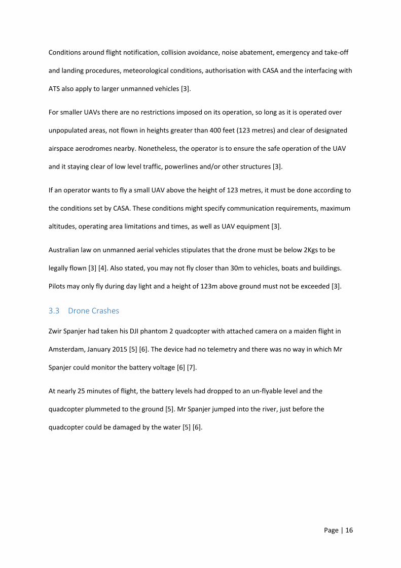
3.3 Drone Crashes
Zwir Spanjer had taken his DJI phantom 2 quadcopter with attached camera on a maiden flight in
Amsterdam, January 2015 [5] [6]. The device had no telemetry and there was no way in which Mr
Spanjer could monitor the battery voltage [6] [7].
At nearly 25 minutes of flight, the battery levels had dropped to an un-flyable level and the
quadcopter plummeted to the ground [5]. Mr Spanjer jumped into the river, just before the
quadcopter could be damaged by the water [5] [6].

Page | 17
Figure 1 - Quadcopter Crash 1 [5]
Ryan Chatfield suffered the same fate. As an inexperienced quadcopter pilot, he was unaware of the
state of his battery and saw the quadcopter start to descend over water [8]. Again, a pilot had to
enter the water to rescue the craft before permanent damage could occur.
Figure 2 - Quadcopter Crash 2 [8]
Page | 18
There are many more examples online of crashes caused by insufficient battery monitoring or
telemetry. It is clear there is a need to display this information to the pilot and give users a clear
indication of what state their battery is in.
3.4 Power Source
Lithium polymer batteries are the most commonly used power sources for untethered devices with
high current consumption. They offer high energy density compared to weight as well as high
discharge rates compared to energy capacity. Quadcopters are of no exception with the market
place offering only Li-Po based solutions for batteries. These batteries have a per cell voltage of 3.7V
with different total voltages achievable through connecting these cells in series. The market place
denotes the number of cells in series by the number of cells followed with an “S”. An example
commonly used by quadcopters is “3S” depicting three cells in series for a total voltage of 11.1V as
shown in Equation 1 - Li-Po Marketing Voltage Calculation.
3 × 3.7𝑉 = 11.1𝑉
Equation 1 - Li-Po Marketing Voltage Calculation
However, the actual voltage per cell when fully charged per cell is 4.2V with fully discharged rated to
3.0V before permanent battery damage occurs [9]. The device ceasing to further consume stored
energy when the battery cell voltage drops below 3.0V helps to prolong battery life and remain
consistent [9] [10] [11].
Li-Po batteries have a C rating which describes the maximum discharge rate while avoiding voltage
sag. The C rating is a multiple of the amp hour capacity. For example, a 1A/h battery with a C rating
of 2, can be safely discharged at 2A and still maintain nominal cell voltage [10].
Page | 19
3.5 Quadcopter Control Algorithms
3.5.1 PID Controller
PID stands for Proportional (P), Integral (I) and Derivative (D). These are the three modes of control
most closed loop controllers are able to operate in, either separately or combined.
The main mode of control is proportional control, which calculated the control action required in
proportion to the error between set point and the process variable. Proportional control is not able
of complete error elimination when implemented on its own.
Integral control is used to eliminate the error, or offset value, that could not be handled by
proportional control only. Implementing an integral term into the control algorithm often leads to
increased instability in the control action [12].
The derivative term can then be added to bring dynamic stability to the process. It has no
functionality of its own.
The three control modes can only be combined as follows [12]:
P on its own, which is used in the most basic controllers.
P combined with I, where the I term eliminated the offset caused by the P term.
P combined with I and D, where the D term eliminated instable
behaviour caused by the I term.
P combined with D, which is mainly used in cascaded control.
I by itself, which is used in the primary controller in cascaded control.
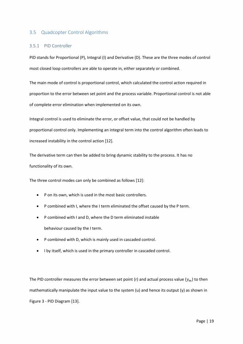
The PID controller measures the error between set point (r) and actual process value (𝑦𝑚) to then
mathematically manipulate the input value to the system (u) and hence its output (y) as shown in
Figure 3 - PID Diagram [13].
Page | 20
Figure 3 - PID Diagram [13]
A change in disturbance will lead to a change in the output variable (y), the controller action should
be able to compensate for most of the disturbances by changing the manipulated variable (u) [13].
3.5.2 Control Algorithms
In the following, a short introduction to Euler angles, Quaternions and Gimbal Lock will be given
before presenting some background research of what other engineers used to design their flight
controllers [12] [14].
Euler angles work well for simple control and analysis and are much more intuitive to use than
quaternions. Their drawback is the limitation of use once a phenomenon called ‘Gimbal Lock’ occurs.
This usually happens when the pitch angle is near +/-90 degrees [12].
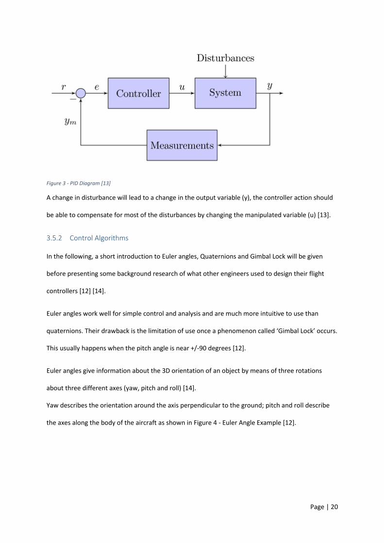
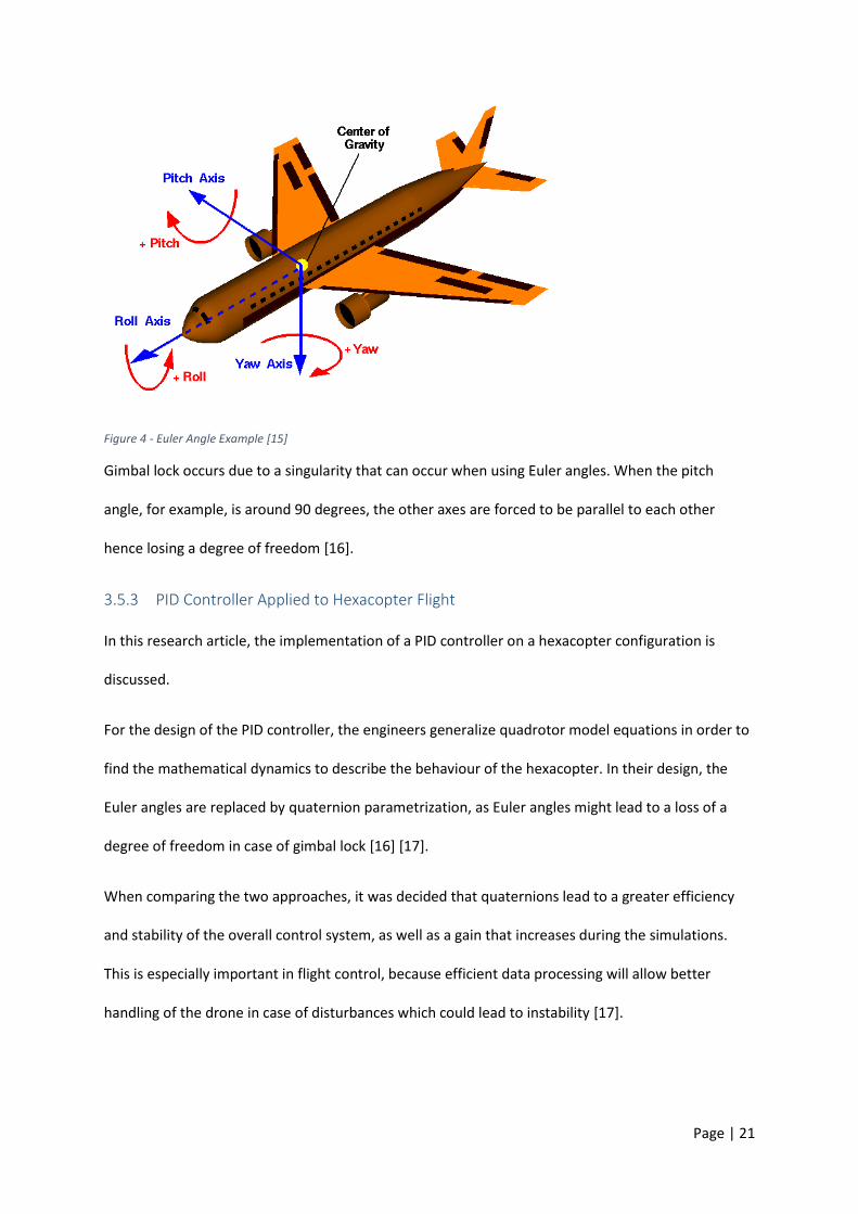
Euler angles give information about the 3D orientation of an object by means of three rotations
about three different axes (yaw, pitch and roll) [14].
Yaw describes the orientation around the axis perpendicular to the ground; pitch and roll describe
the axes along the body of the aircraft as shown in Figure 4 - Euler Angle Example [12].
Page | 21
Figure 4 - Euler Angle Example [15]
Gimbal lock occurs due to a singularity that can occur when using Euler angles. When the pitch
angle, for example, is around 90 degrees, the other axes are forced to be parallel to each other
hence losing a degree of freedom [16].
3.5.3 PID Controller Applied to Hexacopter Flight
In this research article, the implementation of a PID controller on a hexacopter configuration is
discussed.
For the design of the PID controller, the engineers generalize quadrotor model equations in order to
find the mathematical dynamics to describe the behaviour of the hexacopter. In their design, the
Euler angles are replaced by quaternion parametrization, as Euler angles might lead to a loss of a
degree of freedom in case of gimbal lock [16] [17].
When comparing the two approaches, it was decided that quaternions lead to a greater efficiency
and stability of the overall control system, as well as a gain that increases during the simulations.
This is especially important in flight control, because efficient data processing will allow better
handling of the drone in case of disturbances which could lead to instability [17].
Page | 22
The numerical results acquired during the simulation suggest that the position the simulated
hexacopter took overlapped with the checkpoints of its desired path of flight [17]. The required
attitude was reached in a short amount of time and the hovering state was preserved during the
duration of the flight. Moreover, the PID parameters did not have to be changed with desired
positions, which is a promising outcome for implementation of this control strategy into real flights
[17].
3.5.4 MPC and Adaptive Back Stepping
There has been quite some interest in designing unmanned helicopters recently, but due to their
being highly non-linear systems, designing an efficient control system is a challenge for engineers
and researchers. A wide range of control strategies has been applied to these systems, including PID,
LQR and 𝐻∞ control [18].
However, the controllers only achieved a modest performance meaning that the helicopters were
required to fly at a low speed and in a straight line as the tracking accuracy worsen as speed
increases. To obtain acceptable performance, gain scheduling had to be used which results in a
trade-off between flight performance and trim points used [18].
Various nonlinear techniques have been developed in order to overcome the drawbacks of
conventional control, such as feedback linearization, neural networks, and dynamic invasion. These
techniques though are difficult to implement in real flight [18].
Hence, the authors of this research paper proposed an inner-outer loop based flight controller. The
outer loop controls the position and is a slow system. This is the reason the designers used an IMPC
for tracking the reference trajectory. The inner loop is in control of the attitude, a fast system, and
therefore a controller is designed by the means of ABS [18].
This nonlinear control approach uses advantages of the nonlinear rotation and translational
dynamics of the helicopter’s rigid body. The ABS controller estimates the parts ignored by the

Page | 23
dynamic model and any disturbances from the exterior. The researchers’ simulation results showed
the robustness and effectiveness of the design proposed in the paper. This hierarchical control
scheme is easy to implement and simple to tune in case of real flight tests in the future [18].
3.5.5 Modelling and Control
In this paper, the design of a control system for 4kg quadrotor with a payload of 1kg is discussed. It is
making use of custom high-performance blades which are able to lift the quadrotor with a control
margin of an added 30%. The other components such as batteries and motors are all off-the-shelf
components [19].
Basic quadcopter control designs often leave out the effect of blade flapping in their mathematical
modelling. This effect, however, is of highly oscillatory nature and can therefore lead to instabilities
in the overall system, especially when flying at greater heights.
Using automatic compensators will simplify the pilot’s flight experience, as there is no need the
system to be intuitive to a human. Fast reaction to inputs and well design disturbance rejection
measures are desirable for an overall good performance. However, there are limits to the design
choices, as eliminating instability in one area can lead to instability in another one. In the case of the
quadrotor discussed in this paper presented, disturbances which cause noise induction to the inertial
sensors, as well as high frequency disturbances, have to be eliminated [19].
Attitude control has been researched by many universities with the result being that in practice,
simple control schemes such as the PID controller are competitive with the more sophisticated
control schemes. The paper states, that the dynamic regulation performance is +/-2° of level tracking
for most controllers, with some of the best in range controllers being able to stay within +/-0.5-1°
[19].
It is noted that in most cases the conventional PID controller is the favourable choice, due to its
robustness to a variation in parameters and simplicity [19].
Page | 24
Hence, the author designed and implemented a PID controller to stabilise the decoupled roll and
pitch modes. Indoors, the aircraft was able to self-stabilise itself with a precision of +/-1°. Outdoors
the craft was able of short flight with a similar attitude precision. The author also notes that newer
IMU systems could push the control performance of the system by using sampling rates above
100Hz [19].
3.6 Quadcopter Build Options
3.6.1 Enthusiast: Sturdy Quadcopter Build
This quadcopter home project was designed and built by Chris Schroeder and published online on
Instructables, a DIY website.
Schroeder chose the ‘Turnigy Talon Carbon Fibre Quadcopter Frame’ [20] as the quadcopter’s frame
due to its sturdiness. Moreover, it is also relatively inexpensive considering that it is almost
completely build from carbon fibre [21].
Four of the ‘Turnigy L2210A-1650 Brushless Motors’ [20] were chosen for the drive system as they
produce enough lift to lift a camera as well. They are relatively cheap compared to similar high end
cameras and include propeller adapters making it possible to fit propellers of nearly any size [21].
In order to control these motors, Schroeder chose four 25A electronic speed controllers. By varying
the power sent to the motors, the speed can be controlled and are essential for any device using
brushless motors. In conjunction, he uses the ‘BESC’ programming card which is compatible with all
the Turnigy Plush speed controllers and used to program the ESCs [21].
Connected to the motors is a propeller each. The model chosen is the ‘10x4.5SF Props 2pc Standard
Rotation/2 pc Reverse Rotation’. These are 10 inch propellers that have the right dimensions to work
well with the frame chosen for the quadcopter and fit the propeller adapters included in the motor
package [21]. Schroeder later changed to a smaller propeller size as the 10 inch blades turned out to
Page | 25
be too big. He also recommends buying more of these propellers needed as they break the fastest
during a crash and to include a propeller balancer to weight to propellers nicely [21].
The flight controller in this project was chosen to be the ‘HobbyKing KK2.0 Multi-rotor LCD Flight
Control Board’ [20] as it already comes with all the software needed to operate the quadcopter. IT
uses three PID controllers for yaw, pitch and roll with the coefficients being modified in the code and
uploaded via a computer.
The ‘HobbyKing KK2.0 Multi-rotor LCD Flight Control Board’ makes use of a 16 MHz Atmel
Atmega644 PA MCU and an InvenSense 6050MPU to calculate yaw, pitch and roll angles [22].
For the communication link, the Turnigy 6X FHSS 2.4GHz Transmitter and Receiver (Mode1) [20] was
chosen. It provides the operator with six channels for one way communications with the quadcopter
[21].
As a power source, a 2200mA 3S 20C Li-Po Pack was chosen. It consists of three battery cells in series
for a total of 11.1V. The builder states that a higher C rating would allow the motors to draw more
current but this also means that the battery drains quicker [21].
3.6.2 Professional: Walkera – Voyager3 GoPro
The Voyager3 adopts a modular design for its electronic components that are simple to install and
connect making maintenance and upgrading the quadcopter easy. Built-in, is a new generation flight
control system providing a stable flight performance. Its 5.8G image transmission system makes it
easy to get an image and OSD and the indicator lights on the GPS, barometer, compass, as well as
other parts make monitoring the device more intuitive [23].
The Voyager3’s software ‘Ground Station’ works for the Apple IOS as well as Android and is used to
control the quadcopter via a phone or a tablet. On top of that, the quadcopter can also be controlled
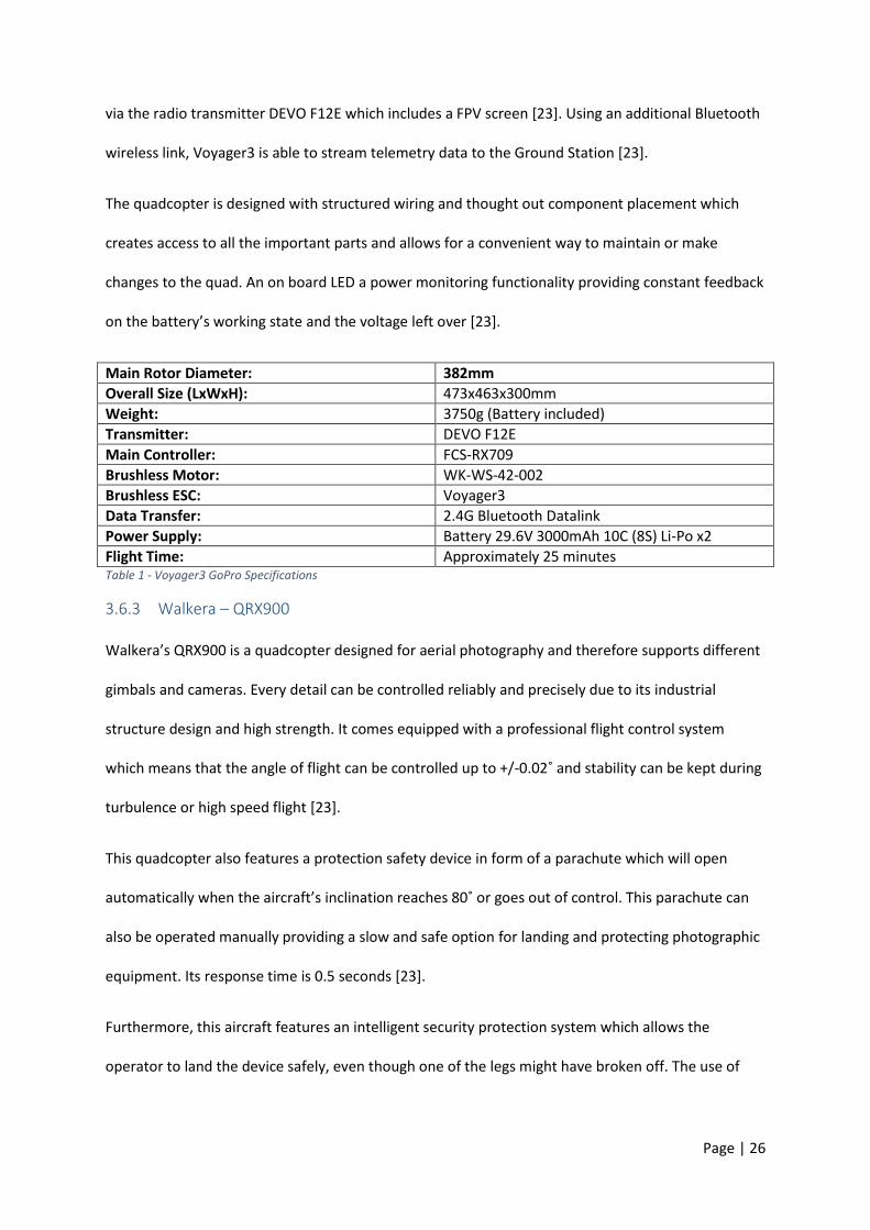
Page | 26
via the radio transmitter DEVO F12E which includes a FPV screen [23]. Using an additional Bluetooth
wireless link, Voyager3 is able to stream telemetry data to the Ground Station [23].
The quadcopter is designed with structured wiring and thought out component placement which
creates access to all the important parts and allows for a convenient way to maintain or make
changes to the quad. An on board LED a power monitoring functionality providing constant feedback
on the battery’s working state and the voltage left over [23].
Main Rotor Diameter: 382mm
Overall Size (LxWxH): 473x463x300mm
Weight: 3750g (Battery included)
Transmitter: DEVO F12E
Main Controller: FCS-RX709
Brushless Motor: WK-WS-42-002
Brushless ESC: Voyager3
Data Transfer: 2.4G Bluetooth Datalink
Power Supply: Battery 29.6V 3000mAh 10C (8S) Li-Po x2
Flight Time: Approximately 25 minutes Table 1 - Voyager3 GoPro Specifications
3.6.3 Walkera – QRX900
Walkera’s QRX900 is a quadcopter designed for aerial photography and therefore supports different
gimbals and cameras. Every detail can be controlled reliably and precisely due to its industrial
structure design and high strength. It comes equipped with a professional flight control system
which means that the angle of flight can be controlled up to +/-0.02˚ and stability can be kept during
turbulence or high speed flight [23].
This quadcopter also features a protection safety device in form of a parachute which will open
automatically when the aircraft’s inclination reaches 80˚ or goes out of control. This parachute can
also be operated manually providing a slow and safe option for landing and protecting photographic
equipment. Its response time is 0.5 seconds [23].
Furthermore, this aircraft features an intelligent security protection system which allows the
operator to land the device safely, even though one of the legs might have broken off. The use of
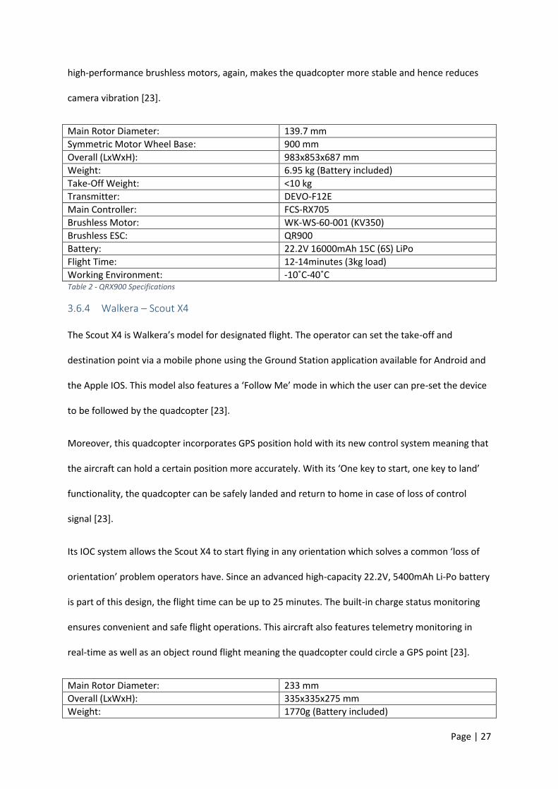
Page | 27
high-performance brushless motors, again, makes the quadcopter more stable and hence reduces
camera vibration [23].
Main Rotor Diameter: 139.7 mm
Symmetric Motor Wheel Base: 900 mm
Overall (LxWxH): 983x853x687 mm
Weight: 6.95 kg (Battery included)
Take-Off Weight: <10 kg
Transmitter: DEVO-F12E
Main Controller: FCS-RX705
Brushless Motor: WK-WS-60-001 (KV350)
Brushless ESC: QR900
Battery: 22.2V 16000mAh 15C (6S) LiPo
Flight Time: 12-14minutes (3kg load)
Working Environment: -10˚C-40˚C Table 2 - QRX900 Specifications
3.6.4 Walkera – Scout X4
The Scout X4 is Walkera’s model for designated flight. The operator can set the take-off and
destination point via a mobile phone using the Ground Station application available for Android and
the Apple IOS. This model also features a ‘Follow Me’ mode in which the user can pre-set the device
to be followed by the quadcopter [23].
Moreover, this quadcopter incorporates GPS position hold with its new control system meaning that
the aircraft can hold a certain position more accurately. With its ‘One key to start, one key to land’
functionality, the quadcopter can be safely landed and return to home in case of loss of control
signal [23].
Its IOC system allows the Scout X4 to start flying in any orientation which solves a common ‘loss of
orientation’ problem operators have. Since an advanced high-capacity 22.2V, 5400mAh Li-Po battery
is part of this design, the flight time can be up to 25 minutes. The built-in charge status monitoring
ensures convenient and safe flight operations. This aircraft also features telemetry monitoring in
real-time as well as an object round flight meaning the quadcopter could circle a GPS point [23].
Main Rotor Diameter: 233 mm
Overall (LxWxH): 335x335x275 mm
Weight: 1770g (Battery included)

Page | 28
Take-Off Weight: <2270g
Transmitter: DEVO-F12E
Receiver: DEVO-RX707(CE)/RX709(FCC)
Brushless Motor: WK-WS-34-002
Brushless ESC: WST-16AH(R/G)
Main Controller: FCS-X4
Battery: 22.2V 5400mAh Li-Po
Software: Ground Station
Data Transfer: 2.4G Bluetooth Link Table 3 - Scout X4
3.6.5 Parrot – AR Drone 2.0
Parrot’s AR Drone 2.0 is designed for aerial photography and lets the user stream recorded footage
straight to a smartphone by using an in-built 720p HD 30FPS camera. The operator can choose the
aircraft’s movements using the ‘Director Mode’ which can be used to program the quadcopter with
automatic movements, as well as allowing real-time speed and move adjustments [24].
To ensure a high quality film making experience, the AR Drone 2.0’s camera also features a 92˚
diagonal wide angle lens and low latency streaming. The user is able to store videos on the remote
device or on a USB key using Wi-Fi [24].
Extreme precision control and stability is achieved through the 1GHz 32-bit ARM Cortex A8
processor with an 800MHz video DSP. The software runs on Linux 2.6.32 and the memory consists of
1GB DDR2 RAM at 200MHz. It also features USB 2.0 high speed for extensions and Wi-Fi for
communications [24].
Sensors used for electronic assistance are a 3-axis gyroscope with 2000˚/second precision, a 3-axis
accelerometer with +/-50mg precision, a 3-axis magnetometer with 6˚ precision, a pressure sensor
with +/-10Pa precision and ultrasonic sensors for ground altitude measurements. The quadcopter
design also includes a 60 FPS vertical QVGA camera measuring the ground speed [24].
The aircraft’s structure is robust thanks to its frame being made out of carbon fibre tubes with a
total weight of 380g with the outdoor hull and 420g with the indoor hull. Moreover, the build
includes 30% fibre charged nylon plastic parts and foam was used to isolate the inertial centre from

Page | 29
engine vibrations. The EPP hull was injected by a metal mould and liquid repellent nano-coating was
applied to the ultrasonic sensors. Moreover, all parts and instructions to repair the frame are
available online [24].
Four powerful 14.4W 28500RPM brushless inrunner motors allow the device to fly fast and high.
Also included are low noise Nylatron gears for a 1/8.75 propeller reductor. The aircraft’s drive
system also features a tempered steel propeller shaft with a bronze bearing that is self-lubricating.
Per fully reprogrammable motor controller, an 8MIPS AVR CPU is installed and the software controls
the emergency stop [24]
3.6.6 Parrot – eXom
This V-shaped quadcopter by Parrot was designed for live building and structure inspections. It
features a fully autonomous mode and an interactive screen flight mode. The user can create geo-
referenced maps and models by using a software called ‘Post Flight Terra 3D’ [25].
The eXom’s flight system consists of four electric brushless motors and four propellers. Its take-off
weight is 1.8kg which includes the battery, shrouding and payload. The flight time of the full system
can be up to 22 minutes and its maximum climb rate is 7 𝑚/𝑠. The maximum air speed that can be
reached in automatic flight is 8 𝑚/𝑠, whereas the aircraft can reach up to 12 𝑚/𝑠 air speed in
manual mode [25].
The autopilot and control is handled by an IMU, a barometer, a magnetometer and a GPS. Its body is
made out of moulded carbon fibre legs and arms and its frame is made of precision-moulded
magnesium. It can operate in a temperature range of -10 to 40˚ [25].
The eXom’s main communication link is established by using digital, dual omnidirectional antennas
that are dual band and encrypted. Their operating frequencies are 2.4GHz and 5GHz ISM bands, but
this depends on the country’s specifications [25].
The digital remote operates on a frequency of 2.4GHz and works over a range of 800metres. The
Page | 30
smart LiPo battery consists out of three cells (3S) and can supply 8500mAh. It comes with an LED
display for on-screen battery information and its charging time is 1-1.5 hours [25].
The quadcopter is controlled by four on-board CPUs; the quad-processor takes care of the artificial
intelligence and the principal autopilot, the dual-core processor handles the video co-processing,
and on of single core processors takes care of the low-level autopilot as a safety fall-back and the
motor control, whereas the other one manages the communication link [25].
3.7 Market Recap
Clearly, there is a need to introduce some functionality only found in expensive flight controllers to
ensure safe flight. Making use of bi-directional wireless communications will reduce the cost of these
components and also the weight.
Page | 31
4 Quadcopter Physical Structure
This chapter introduces the components used to test the flight controller [26]. It will include:
A frame to which all components are connected.
Electric motors and propeller combination.
Electric motor speed controllers or a Variable speed drive.
Power Source
This document refers to the “Chassis” as the combination of the frame, electric speed controllers
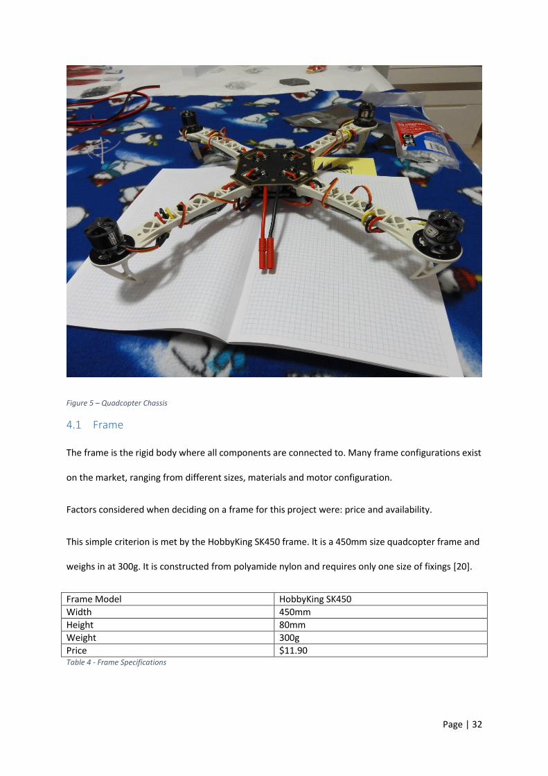
(ESCs), motors, propellers and battery as shown in Figure 5 – Quadcopter Chassis. The design is to
have a thrust to weight ratio of 2:1 as stated from many online forums such as [26] [27] and [28].
All Chassis components were purchased from HobbyKing.com as at the time of purchase offered the
most competitive pricing. The frame was chosen because it was the cheapest option at $11.90
including delivery. The remaining components for this frame were recommended by HobbyKing.com
as being appropriately sized for the application [20].
Page | 32
Figure 5 – Quadcopter Chassis
4.1 Frame
The frame is the rigid body where all components are connected to. Many frame configurations exist
on the market, ranging from different sizes, materials and motor configuration.
Factors considered when deciding on a frame for this project were: price and availability.
This simple criterion is met by the HobbyKing SK450 frame. It is a 450mm size quadcopter frame and
weighs in at 300g. It is constructed from polyamide nylon and requires only one size of fixings [20].
Frame Model HobbyKing SK450
Width 450mm
Height 80mm
Weight 300g
Price $11.90 Table 4 - Frame Specifications
Page | 33
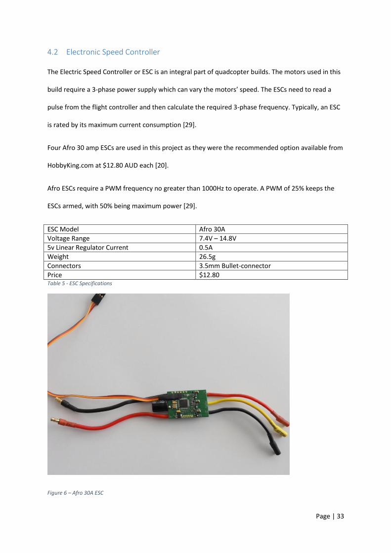
4.2 Electronic Speed Controller
The Electric Speed Controller or ESC is an integral part of quadcopter builds. The motors used in this
build require a 3-phase power supply which can vary the motors’ speed. The ESCs need to read a
pulse from the flight controller and then calculate the required 3-phase frequency. Typically, an ESC
is rated by its maximum current consumption [29].
Four Afro 30 amp ESCs are used in this project as they were the recommended option available from
HobbyKing.com at $12.80 AUD each [20].
Afro ESCs require a PWM frequency no greater than 1000Hz to operate. A PWM of 25% keeps the
ESCs armed, with 50% being maximum power [29].
ESC Model Afro 30A
Voltage Range 7.4V – 14.8V
5v Linear Regulator Current 0.5A
Weight 26.5g
Connectors 3.5mm Bullet-connector
Price $12.80 Table 5 - ESC Specifications
Figure 6 – Afro 30A ESC
Page | 34
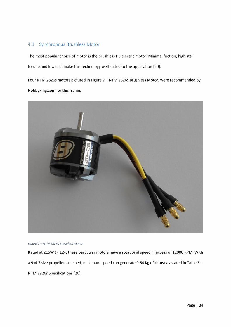
4.3 Synchronous Brushless Motor
The most popular choice of motor is the brushless DC electric motor. Minimal friction, high stall
torque and low cost make this technology well suited to the application [20].
Four NTM 2826s motors pictured in Figure 7 – NTM 2826s Brushless Motor, were recommended by
HobbyKing.com for this frame.
Figure 7 – NTM 2826s Brushless Motor
Rated at 215W @ 12v, these particular motors have a rotational speed in excess of 12000 RPM. With
a 9x4.7 size propeller attached, maximum speed can generate 0.64 Kg of thrust as stated in Table 6 -
NTM 2826s Specifications [20].
Page | 35
Motor Model NTM 2826s
RPM per Volt 1000Kv
Weight 54g
Connection 3.5mm Bullet-connector
Maximum Voltage 15V
Maximum Thrust with 9x4.7 size Propeller 0.64Kg Table 6 - NTM 2826s Specifications
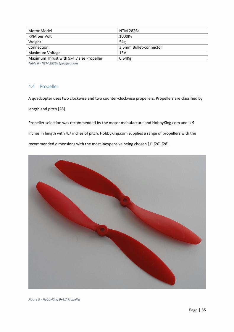
4.4 Propeller
A quadcopter uses two clockwise and two counter-clockwise propellers. Propellers are classified by
length and pitch [28].
Propeller selection was recommended by the motor manufacture and HobbyKing.com and is 9
inches in length with 4.7 inches of pitch. HobbyKing.com supplies a range of propellers with the
recommended dimensions with the most inexpensive being chosen [1] [20] [28].
Figure 8 - HobbyKing 9x4.7 Propeller
Page | 36
Propeller Model HobbyKing 9x4.7
Length 9 inches
Pitch 4.7 inches
Weight 7.1g
Material Nylon
Price $1.12 Table 7 - Propeller Specifications
4.5 Battery
Commonly used in radio controlled devices requiring high current, Lithium Polymer or Li-Po batteries
are a popular choice because of their energy density and their ability to be made into any size [21]
[30]. These batteries have high discharge rates making them well suited to high current applications
such as quadcopters [10] [20] [26].
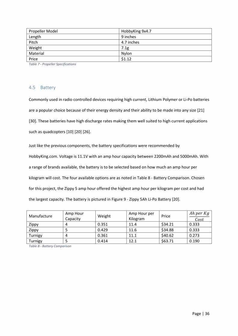
Just like the previous components, the battery specifications were recommended by
HobbyKing.com. Voltage is 11.1V with an amp hour capacity between 2200mAh and 5000mAh. With
a range of brands available, the battery is to be selected based on how much an amp hour per
kilogram will cost. The four available options are as noted in Table 8 - Battery Comparison. Chosen
for this project, the Zippy 5 amp hour offered the highest amp hour per kilogram per cost and had
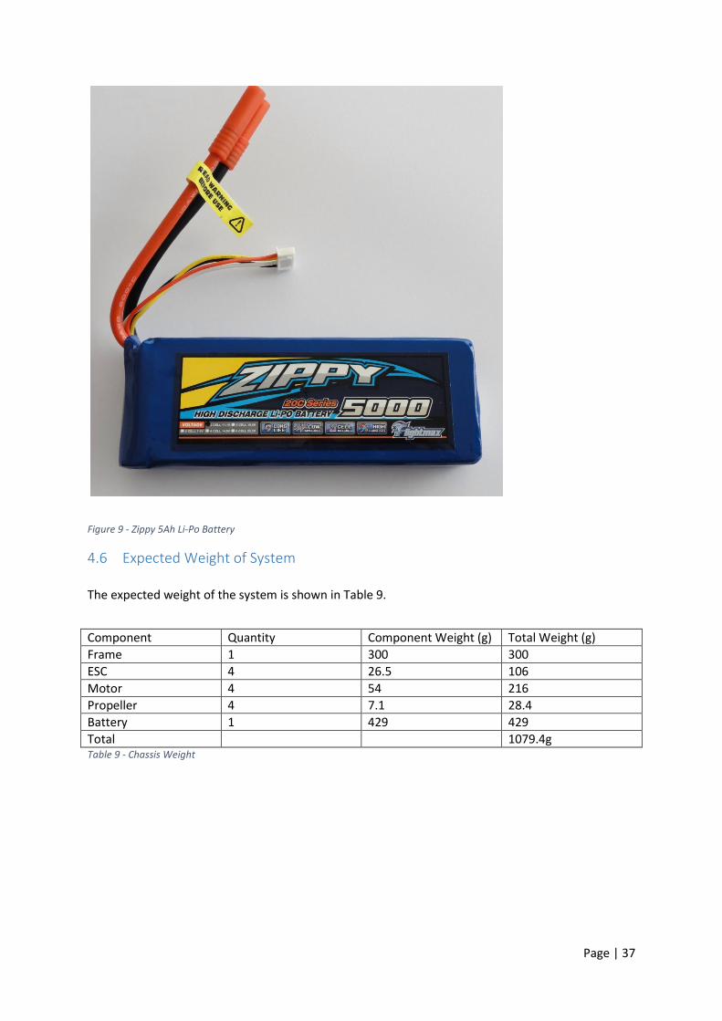
the largest capacity. The battery is pictured in Figure 9 - Zippy 5Ah Li-Po Battery [20].
Manufacture Amp Hour Capacity
Weight Amp Hour per Kilogram
Price 𝐴ℎ 𝑝𝑒𝑟 𝐾𝑔
𝐶𝑜𝑠𝑡
Zippy 4 0.351 11.4 $34.21 0.333
Zippy 5 0.429 11.6 $34.88 0.333
Turnigy 4 0.361 11.1 $40.62 0.273
Turnigy 5 0.414 12.1 $63.71 0.190 Table 8 - Battery Comparison
Page | 37
Figure 9 - Zippy 5Ah Li-Po Battery
4.6 Expected Weight of System
The expected weight of the system is shown in Table 9.
Component Quantity Component Weight (g) Total Weight (g)
Frame 1 300 300
ESC 4 26.5 106
Motor 4 54 216
Propeller 4 7.1 28.4
Battery 1 429 429
Total 1079.4g Table 9 - Chassis Weight

Page | 38
5 Software
This chapter will introduce the development environment and the protocols used in this project.
5.1 Integrated Development Environment (IDE)
The integrated development environment (IDE) is a software application designed to aid
development of programs. An IDE consists of a code editor, compiler and debugger with many
modern versions having a form of intelligent code completion [31].
5.1.1 Atmel Studio 6.2
Atmel studio 6.2 is the development environment used to design, test and compile code used in this
project. It supports all Atmel MCUs including the SAM3 architecture used in this project and can
seamlessly integrate with other platforms which use Atmel devices such as Arduino [31].
5.1.2 Atmel Software Framework
The Atmel Software Framework or ASF provides software drivers and libraries to build applications
for a range of Atmel microcontroller units including SAM devices. An abstraction to hardware which
closely resembles register names used in the respective MCU datasheets simplifies and speeds up
development [31].
5.2 C/C++ Language
C and C++ are the programming languages used in this project. C is a powerful low level language but
lacks many of the modern accessibility and usefulness of constructs. C++ is a much newer language,
which as the name suggests, is based on C. It adds many more modern programming language
features that make programming in C much easier. Features such as object-oriented programming
and constructs make the writing of code much more streamlined so an end result can be achieved in
less time [32].
Page | 39
5.3 Protocols
5.3.1 SPI
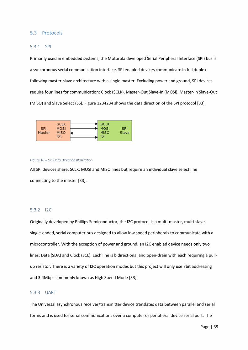
Primarily used in embedded systems, the Motorola developed Serial Peripheral Interface (SPI) bus is
a synchronous serial communication interface. SPI enabled devices communicate in full duplex
following master-slave architecture with a single master. Excluding power and ground, SPI devices
require four lines for communication: Clock (SCLK), Master-Out Slave-In (MOSI), Master-In Slave-Out
(MISO) and Slave Select (SS). Figure 1234234 shows the data direction of the SPI protocol [33].
Figure 10 – SPI Data Direction Illustration
All SPI devices share: SCLK, MOSI and MISO lines but require an individual slave select line
connecting to the master [33].
5.3.2 I2C
Originally developed by Phillips Semiconductor, the I2C protocol is a multi-master, multi-slave,
single-ended, serial computer bus designed to allow low speed peripherals to communicate with a
microcontroller. With the exception of power and ground, an I2C enabled device needs only two
lines: Data (SDA) and Clock (SCL). Each line is bidirectional and open-drain with each requiring a pull-
up resistor. There is a variety of I2C operation modes but this project will only use 7bit addressing
and 3.4Mbps commonly known as High Speed Mode [33].
5.3.3 UART
The Universal asynchronous receiver/transmitter device translates data between parallel and serial
forms and is used for serial communications over a computer or peripheral device serial port. The
Page | 40
sending UART takes bytes of data and transmits the individual bits sequentially. The receiving UART
re-assembles the bits into complete bytes and stores the data in a buffer for a host device to retrieve
[34].
5.3.4 NMEA 0183
The National Marine Electronics Association defined the NMEA 0813 protocol to consolidate
communications of instruments such as sonars and GPS receivers. NMEA is the standard in GPS
communications and is comparable to ASCII for digital characters for computers. There are a number
of deferent NMEA messages but this project is only considering NMEA $GPGGA or Global Positioning
System Fix Data [35].
5.3.5 IEEE 802.15.4
Maintained by the IEEE 802.15 group, the 802.15.4 standard specifies the physical layer and access
control for low-rate wireless personal area networks (LR-WPAN) emphasising on low cost
communication of nearby devices [33] [36].
Page | 41
6 Electrical Components
This chapter describes the sensors and electrical components used in this project. It is explained how
these devices work and how they were tested.
6.1 Arduino Platform
Arduino being an open-source prototyping platform combines Atmel micro-controllers and
supporting hardware with external connectors allowing the microcontroller to communicate with
external devices with no extra breakout boards. With the popularity of Arduino increasing and the
open-source nature of the platform, the Chinese-clone boards have become relatively cheap and
offer the most performance per dollar [37] [38] [39].
Board MHz Digital IO IO Voltage Arduino Price Clone Price MHz per $
Due 84 55 3.3v $106.00 $21.00 4
Mega 16 53 5v $86.00 $18.90 0.85
Uno 16 13 5v $48.95 $11.99 1.33
Table 10 - Arduino Price Comparison
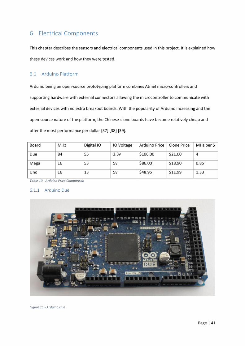
6.1.1 Arduino Due
Figure 11 - Arduino Due

Page | 42
Shown in Table 10 - Arduino Price Comparison, the chosen MCU pictured in Figure 11 - Arduino Due
is the most powerful edition of the Arduino range running at 84 MHz and has the most clock cycles
per dollar. It uses an on-board buck converter, pictured in Figure 12 – Arduino Due Buck Converter,
to step down the input voltage as opposed to a linear regulator minimising wasted energy and
prolonging the potential flight time [38] [40].
Figure 12 – Arduino Due Buck Converter
Figure 13 – Texus Instruments LM2734 Load Current verses Efficiency
This board is expected to consume over 150mA as stated on the Arduino website [38]. The DC-DC
converter used on the board is a Texas Instruments LM2734 and with the expected current
Page | 43
consumed through the device it should have an efficiency of 90% as shown in Figure 13 – Texus
Instruments LM2734 Load Current verses Efficiency [40].
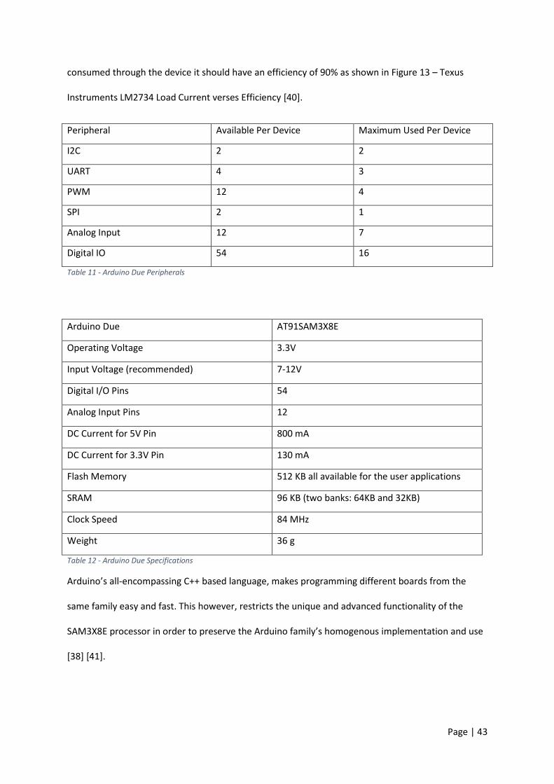
Peripheral Available Per Device Maximum Used Per Device
I2C 2 2
UART 4 3
PWM 12 4
SPI 2 1
Analog Input 12 7
Digital IO 54 16
Table 11 - Arduino Due Peripherals
Arduino Due AT91SAM3X8E
Operating Voltage 3.3V
Input Voltage (recommended) 7-12V
Digital I/O Pins 54
Analog Input Pins 12
DC Current for 5V Pin 800 mA
DC Current for 3.3V Pin 130 mA
Flash Memory 512 KB all available for the user applications
SRAM 96 KB (two banks: 64KB and 32KB)
Clock Speed 84 MHz
Weight 36 g
Table 12 - Arduino Due Specifications
Arduino’s all-encompassing C++ based language, makes programming different boards from the
same family easy and fast. This however, restricts the unique and advanced functionality of the
SAM3X8E processor in order to preserve the Arduino family’s homogenous implementation and use
[38] [41].
Page | 44
6.1.2 Atmel SAM3X8E
The Atmel AT91SAM3X8E has a series of advanced capabilities that will aid in the flight controller
and radio system’s implementation. This processor has 9 timers that are separate from timers used
in the delay function. AVR based Arduinos use timer 0 as the millisecond timer for delay and any
changes to the timers clock divider will affect the ‘delay()’ function [38] [41].
SAM3X based MCUs include an advanced Waveform Mode which can be coupled to external I/O,
reducing computational time required to interface with ESCs. Error! Reference source not found.
graphically displays a configured timer which is compared to three different values: RA, RB and RC.
RA and RB toggle two separate external I/Os and the RC compare resets the counter. In this
implementation, RA and RB control both PWM signals to two separate ESCs, with RC setting the
PWM period [41].
6.2 IMU
Calculating the orientation of the quadcopter is done with an IMU fixed to the centre of the chassis.
Required of the IMU is the ability to measure absolute orientation with the data presented in Euler
form at a rate no less than 100Hz. The device must easily interface with a microcontroller with only
minor physical construction such as the soldering of power or data connections, is to be readily
available and below $40.00.
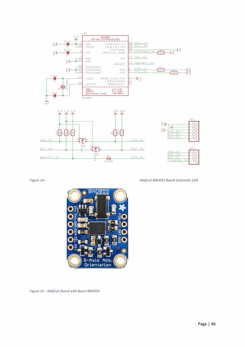
Table 13 - IMU Available Options contains three possible readily available options. Shown in Figure
15 – Adafruit Board with Bosch BNO055, the Bosch IMU was chosen as it met the requirements
stated above [42].
IMU Data Rate Data Output
External Components
Other than Power/Data
Interface Cost
Bosch BNO055 100Hz Euler No I2C $40.00
Invensense 31.25Hz RAW with onboard
Pullup Resisters I2C $32.50

Page | 45
MPU9250 filtering Required
Freescale MMA7361LC
300Hz RAW No Analog $19.95
Table 13 - IMU Available Options [43] [44] [45]
The Bosch BNO055 is a System in Package (SiP) which combines three motion sensors and a 32bit
processor which performs a sensor fusion to achieve absolute orientation. The three sensors used
are: an accelerometer, a gyroscope and a geomagnetic sensor, each of which can measure changes
in three axes [42].
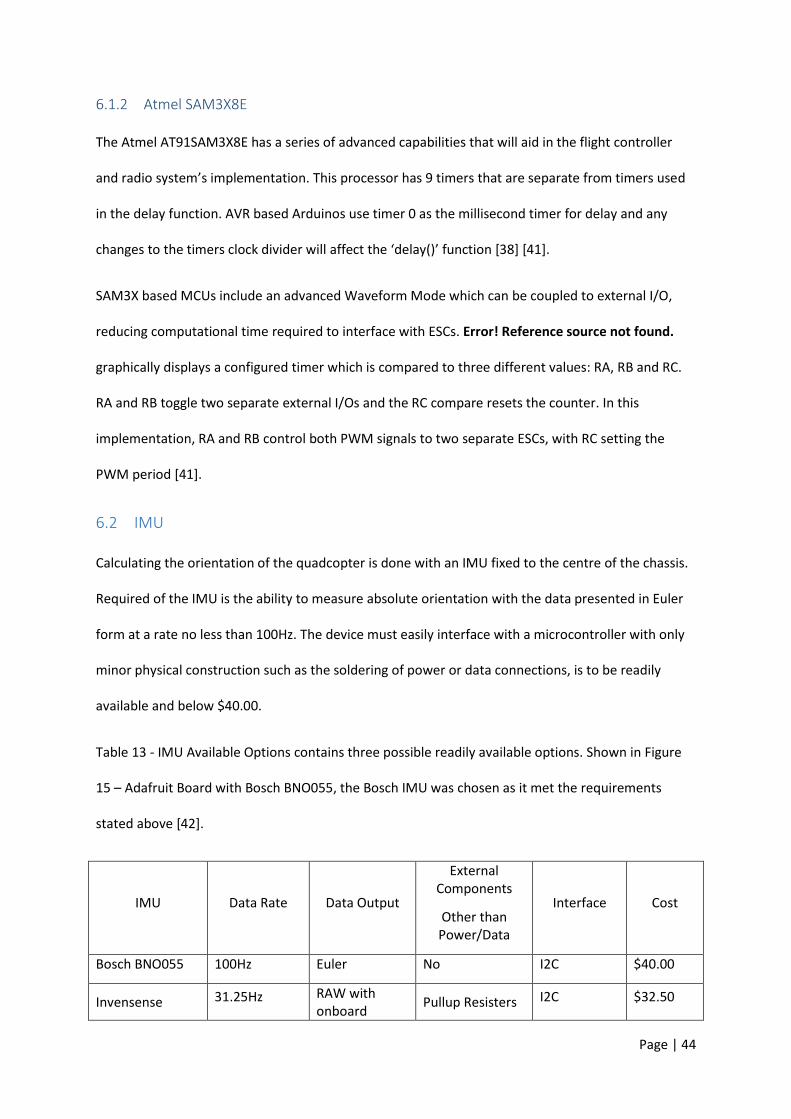
This project uses the Adafruit BNO055 breakout board to find the quadcopter’s absolute position. To
simplify the calculations of orientation, the IMU must be able to output data in Euler form. Absolute
orientation is in the form of Euler vectors and is polled at 100Hz [42]. This sensor is designed to be
used with embedded systems where accurate orientation is required. This board allows an input
voltage of 3.3 to 5v and the I2C clock and data pins have 10kΩ pullup resistors as shown in Figure 14
– Adafruit BNO055 Board Schematic and a reset pin capable of resetting the device without power
cycling [43].
Page | 46
Figure 14 – Adafruit BNO055 Board Schematic [43]
Figure 15 – Adafruit Board with Bosch BNO055
Page | 47
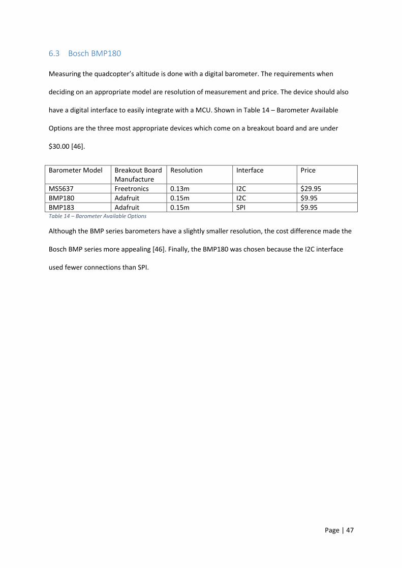
6.3 Bosch BMP180
Measuring the quadcopter’s altitude is done with a digital barometer. The requirements when
deciding on an appropriate model are resolution of measurement and price. The device should also
have a digital interface to easily integrate with a MCU. Shown in Table 14 – Barometer Available
Options are the three most appropriate devices which come on a breakout board and are under
$30.00 [46].
Barometer Model Breakout Board Manufacture
Resolution Interface Price
MS5637 Freetronics 0.13m I2C $29.95
BMP180 Adafruit 0.15m I2C $9.95
BMP183 Adafruit 0.15m SPI $9.95 Table 14 – Barometer Available Options
Although the BMP series barometers have a slightly smaller resolution, the cost difference made the
Bosch BMP series more appealing [46]. Finally, the BMP180 was chosen because the I2C interface
used fewer connections than SPI.

Page | 48
6.4 Ublox NEO 6M GPS
In order to calculate approximate altitude, GPS is used in combination with a barometer to initially
calculate approximate sea level pressure. As this device only needs to be running during the start-up
process, cost is the only factor in the selection criteria [47].
GPS IC Breakout Board Manufacturer Cost
uBlox NEO-6M Chinese Clone $14.85
EM-506 Sparkfun $55.43
MTK3339 Adafruit $55.43
Table 15 - Available GPS Options
The NEO 6M GPS by Ublox is the most cost effective solution which was readily available during the
component selection phase. It is designed to work with embedded systems or PCs through a
communications interface limited to UART, USB and Serial Peripheral Interface (SPI) [48]. Figure 16 -
ublox NEO 6M GPS Module, is the chosen breakout board purchased online from Ebay [37] [47] . The
board has the supporting hardware for UART communications, a 432RP EEPROM used to store
configuration data and an uFL SMT Antenna connector for an included external ceramic antenna
[48]. The board has no other version markings except for GY-GPS6MV2.
Figure 16 - ublox NEO 6M GPS Module
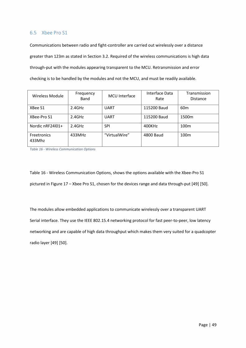
Page | 49
6.5 Xbee Pro S1
Communications between radio and fight-controller are carried out wirelessly over a distance
greater than 123m as stated in Section 3.2. Required of the wireless communications is high data
through-put with the modules appearing transparent to the MCU. Retransmission and error
checking is to be handled by the modules and not the MCU, and must be readily available.
Wireless Module Frequency
Band MCU Interface
Interface Data Rate
Transmission Distance
XBee S1 2.4GHz UART 115200 Baud 60m
XBee-Pro S1 2.4GHz UART 115200 Baud 1500m
Nordic nRF24l01+ 2.4GHz SPI 400KHz 100m
Freetronics 433Mhz
433MHz “VirtualWire” 4800 Baud 100m
Table 16 - Wireless Communication Options
Table 16 - Wireless Communication Options, shows the options available with the Xbee-Pro S1
pictured in Figure 17 – Xbee Pro S1, chosen for the devices range and data through-put [49] [50].
The modules allow embedded applications to communicate wirelessly over a transparent UART
Serial interface. They use the IEEE 802.15.4 networking protocol for fast peer-to-peer, low latency
networking and are capable of high data throughput which makes them very suited for a quadcopter
radio layer [49] [50].
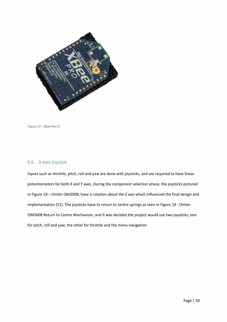
Page | 50
Figure 17 – Xbee Pro S1
6.6 3-Axis Joystick
Inputs such as throttle, pitch, roll and yaw are done with joysticks, and are required to have linear
potentiometers for both X and Y axes. During the component selection phase, the joysticks pictured
in Figure 18 – Omter OM300B, have a rotation about the Z axis which influenced the final design and
implementation [51]. The joysticks have to return to centre springs as seen in Figure 19 - Omter
OM300B Return to Centre Mechanism, and it was decided the project would use two joysticks; one
for pitch, roll and yaw; the other for throttle and the menu navigation.

Page | 51
Figure 18 – Omter OM300B Top
Figure 19 - Omter OM300B Return to Centre Mechanism
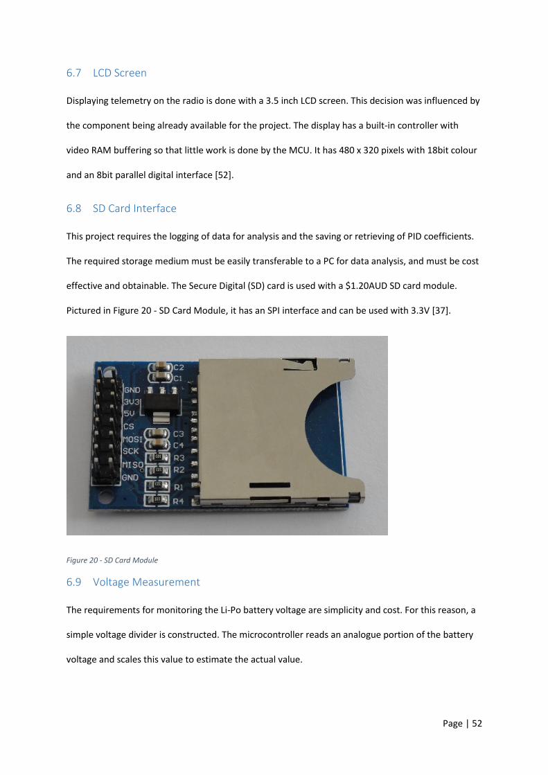
Page | 52
6.7 LCD Screen
Displaying telemetry on the radio is done with a 3.5 inch LCD screen. This decision was influenced by
the component being already available for the project. The display has a built-in controller with
video RAM buffering so that little work is done by the MCU. It has 480 x 320 pixels with 18bit colour
and an 8bit parallel digital interface [52].
6.8 SD Card Interface
This project requires the logging of data for analysis and the saving or retrieving of PID coefficients.
The required storage medium must be easily transferable to a PC for data analysis, and must be cost
effective and obtainable. The Secure Digital (SD) card is used with a $1.20AUD SD card module.
Pictured in Figure 20 - SD Card Module, it has an SPI interface and can be used with 3.3V [37].
Figure 20 - SD Card Module
6.9 Voltage Measurement
The requirements for monitoring the Li-Po battery voltage are simplicity and cost. For this reason, a
simple voltage divider is constructed. The microcontroller reads an analogue portion of the battery
voltage and scales this value to estimate the actual value.

Page | 53
7 Design Strategy
The quadcopter flight controller and radio system have been developed concurrently with certain
aspects being shared between both devices. All stages are tested individually and then again when
combined to ensure an error-free run. Figure 21 - Design Process of Project, shows the intended
design sequence starting at the bottom with Quadcopter and Radio. The hardware timers and
interrupts are then configured for each device with the allocated sensors being tested and read
after. Communications between both devices are should then be established followed by the PID
control loops and the modifications to the respected coefficients. Finally, restrictions are to be set in
place after testing of the prior steps with data logging finalising the project.
Logging
Flight Restrictions
PID Auto Hover PID Coefficients
PID Yaw, Pitch Roll
Communications
Read Sensors
Interrupts – Timers – Hardware Waveforms
Quadcopter Radio
Figure 21 - Design Process of Project
7.1 Pseudo Scheduler System
The purpose of this system is to quickly identify possible timing issues when dealing with multiple
sensors and calculations. This is a method to display what the MCU is or is not spending
computational time on. The “Pseudo Scheduler” essentially divides the processor’s time into two
parts; programOne() and programTwo(). Governing which program is to run at a given moment, a
software interrupt is used to toggle a Boolean value at twice the IMU data rate of 200Hz and toggle
the state of an external I/O pin called “clock”. The value is then checked in the program loop and if
true, programOne() is run and the vice versa. After programOne has completed the required tasks,
another external I/O pin named “freeTime” is set high and the scheduling system remains dormant

Page | 54
in a while loop until the next interrupt. When the interrupt toggles the state of the Boolean value
and the state of “clock”, the “freeTime” I/O pin is set low and the whole process starts again for
programTwo().
Figure 22 shows the above description graphically with the orange trace depicting “clock” and the
blue trace depicting the remaining “freeTime” in the program.
Figure 22 – Pseudo Scheduler Example
The clock will toggle the Arduino Dues’ pin 24, and the “freeTime” will toggle pin 26.
7.2 Radio Communications Packet Structure
The bidirectional communications between the quadcopter and the radio system are a fixed length
of ASCII characters designed to simplify the deconstruction at the receiving end. There are two
packets, one originating from the radio console and the other from the quadcopter.
The out-going radio packet is divided into six parts, each consisting of three ASCII characters. These
characters represent a three digit hexadecimal number with the largest value being 0xFFF or 4095.
This conforms to the SAM3X8E analogue to digital converter having 12Bit resolution and is the most
compact number representative.
Pseudo Scheduler
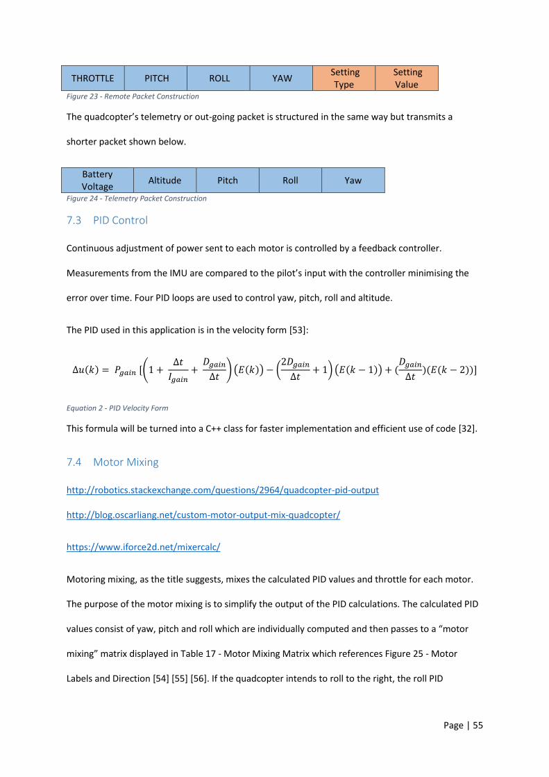
Page | 55
THROTTLE PITCH ROLL YAW Setting
Type Setting Value
Figure 23 - Remote Packet Construction
The quadcopter’s telemetry or out-going packet is structured in the same way but transmits a
shorter packet shown below.
Battery Voltage
Altitude Pitch Roll Yaw
Figure 24 - Telemetry Packet Construction
7.3 PID Control
Continuous adjustment of power sent to each motor is controlled by a feedback controller.
Measurements from the IMU are compared to the pilot’s input with the controller minimising the
error over time. Four PID loops are used to control yaw, pitch, roll and altitude.
The PID used in this application is in the velocity form [53]:
Δ𝑢(𝑘) = 𝑃𝑔𝑎𝑖𝑛 [(1 + Δ𝑡
𝐼𝑔𝑎𝑖𝑛+
𝐷𝑔𝑎𝑖𝑛
Δ𝑡) (𝐸(𝑘)) − (
2𝐷𝑔𝑎𝑖𝑛
Δ𝑡+ 1) (𝐸(𝑘 − 1)) + (
𝐷𝑔𝑎𝑖𝑛
Δ𝑡)(𝐸(𝑘 − 2))]
Equation 2 - PID Velocity Form
This formula will be turned into a C++ class for faster implementation and efficient use of code [32].
7.4 Motor Mixing
http://robotics.stackexchange.com/questions/2964/quadcopter-pid-output
http://blog.oscarliang.net/custom-motor-output-mix-quadcopter/
https://www.iforce2d.net/mixercalc/
Motoring mixing, as the title suggests, mixes the calculated PID values and throttle for each motor.
The purpose of the motor mixing is to simplify the output of the PID calculations. The calculated PID
values consist of yaw, pitch and roll which are individually computed and then passes to a “motor
mixing” matrix displayed in Table 17 - Motor Mixing Matrix which references Figure 25 - Motor
Labels and Direction [54] [55] [56]. If the quadcopter intends to roll to the right, the roll PID
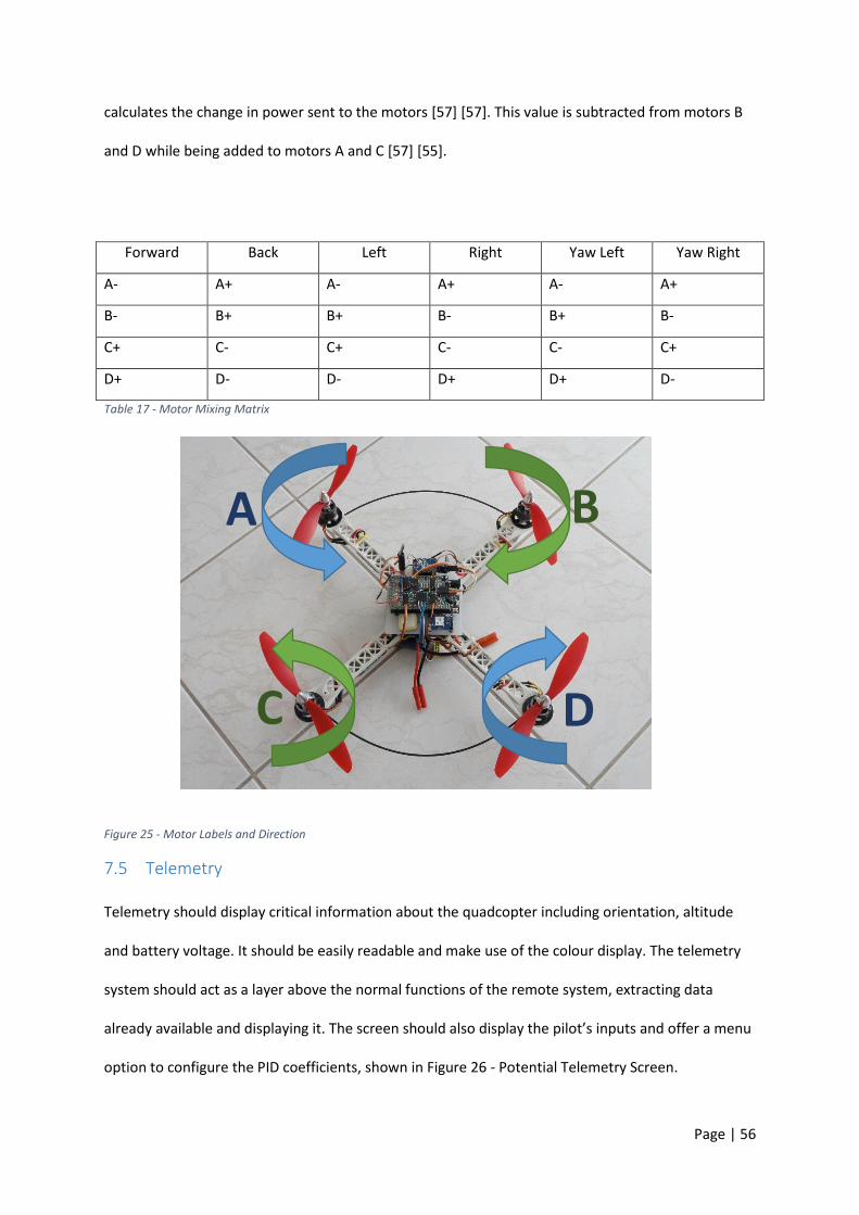
Page | 56
calculates the change in power sent to the motors [57] [57]. This value is subtracted from motors B
and D while being added to motors A and C [57] [55].
Forward Back Left Right Yaw Left Yaw Right
A- A+ A- A+ A- A+
B- B+ B+ B- B+ B-
C+ C- C+ C- C- C+
D+ D- D- D+ D+ D-
Table 17 - Motor Mixing Matrix
Figure 25 - Motor Labels and Direction
7.5 Telemetry
Telemetry should display critical information about the quadcopter including orientation, altitude
and battery voltage. It should be easily readable and make use of the colour display. The telemetry
system should act as a layer above the normal functions of the remote system, extracting data
already available and displaying it. The screen should also display the pilot’s inputs and offer a menu
option to configure the PID coefficients, shown in Figure 26 - Potential Telemetry Screen.
A B
C D
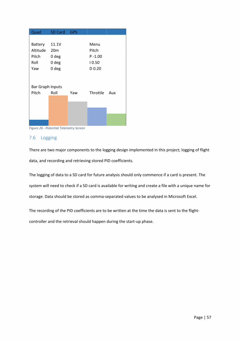
Page | 57
Quad SD Card GPS
Battery 11.1V
Menu
Altitude 20m
Pitch
Pitch 0 deg
P -1.00
Roll 0 deg
I 0.50
Yaw 0 deg
D 0.20
Bar Graph Inputs
Pitch Roll Yaw Throttle Aux
Figure 26 - Potential Telemetry Screen
7.6 Logging
There are two major components to the logging design implemented in this project; logging of flight
data, and recording and retrieving stored PID coefficients.
The logging of data to a SD card for future analysis should only commence if a card is present. The
system will need to check if a SD card is available for writing and create a file with a unique name for
storage. Data should be stored as comma-separated values to be analysed in Microsoft Excel.
The recording of the PID coefficients are to be written at the time the data is sent to the flight-
controller and the retrieval should happen during the start-up phase.
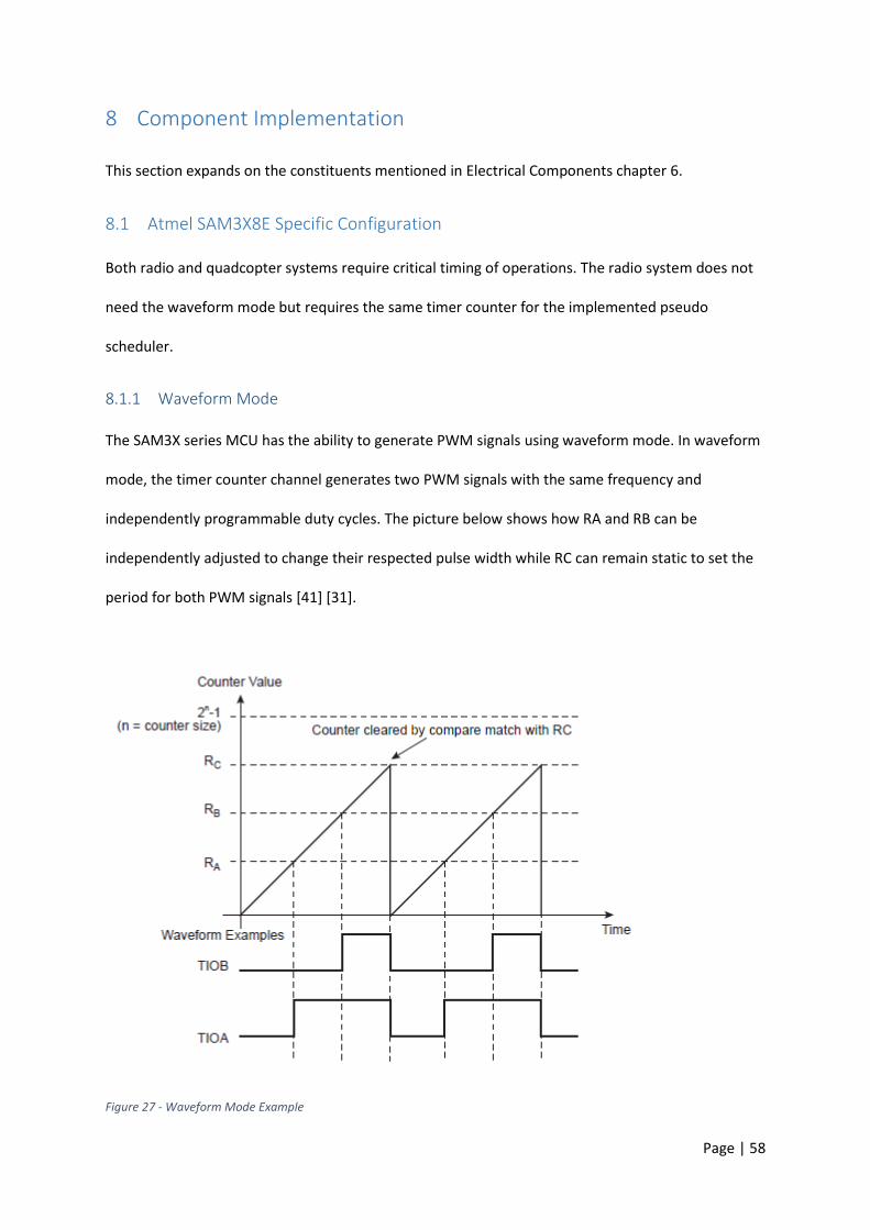
Page | 58
8 Component Implementation
This section expands on the constituents mentioned in Electrical Components chapter 6.
8.1 Atmel SAM3X8E Specific Configuration
Both radio and quadcopter systems require critical timing of operations. The radio system does not
need the waveform mode but requires the same timer counter for the implemented pseudo
scheduler.
8.1.1 Waveform Mode
The SAM3X series MCU has the ability to generate PWM signals using waveform mode. In waveform
mode, the timer counter channel generates two PWM signals with the same frequency and
independently programmable duty cycles. The picture below shows how RA and RB can be
independently adjusted to change their respected pulse width while RC can remain static to set the
period for both PWM signals [41] [31].
Figure 27 - Waveform Mode Example
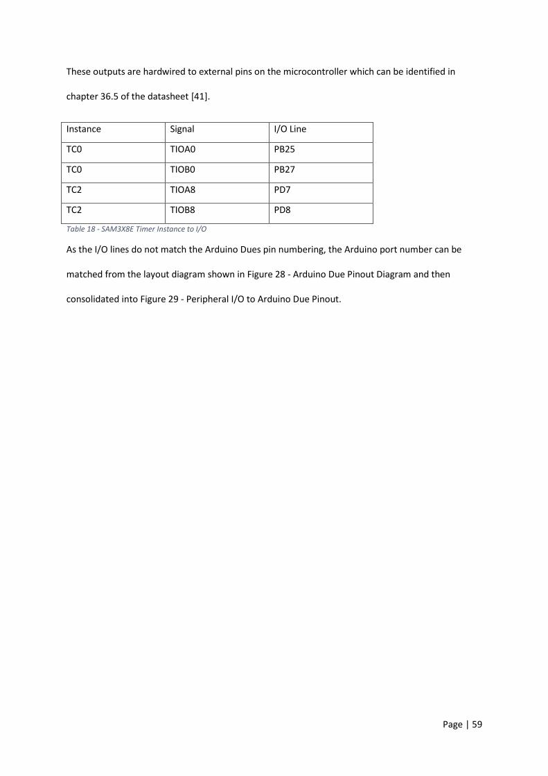
Page | 59
These outputs are hardwired to external pins on the microcontroller which can be identified in
chapter 36.5 of the datasheet [41].
Instance Signal I/O Line
TC0 TIOA0 PB25
TC0 TIOB0 PB27
TC2 TIOA8 PD7
TC2 TIOB8 PD8
Table 18 - SAM3X8E Timer Instance to I/O
As the I/O lines do not match the Arduino Dues pin numbering, the Arduino port number can be
matched from the layout diagram shown in Figure 28 - Arduino Due Pinout Diagram and then
consolidated into Figure 29 - Peripheral I/O to Arduino Due Pinout.
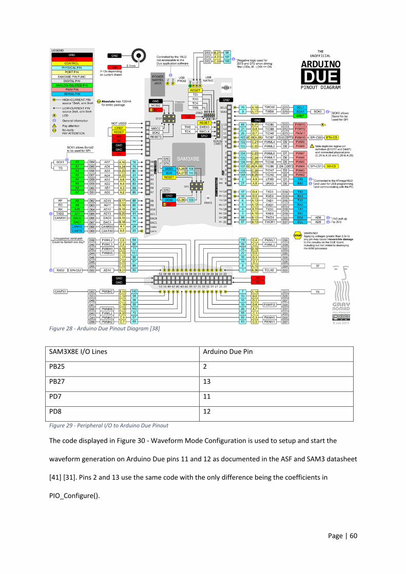
Page | 60
Figure 28 - Arduino Due Pinout Diagram [38]
SAM3X8E I/O Lines Arduino Due Pin
PB25 2
PB27 13
PD7 11
PD8 12
Figure 29 - Peripheral I/O to Arduino Due Pinout
The code displayed in Figure 30 - Waveform Mode Configuration is used to setup and start the
waveform generation on Arduino Due pins 11 and 12 as documented in the ASF and SAM3 datasheet
[41] [31]. Pins 2 and 13 use the same code with the only difference being the coefficients in
PIO_Configure().

Page | 61
Figure 30 - Waveform Mode Configuration
8.1.2 Timer Counter
Software interrupts on Atmel SAM devices can be triggered by an internal timer compare. There are
three 32Bit identical Timer Counter (TC) channels which can be independently programmed to
perform a wide range of functions as described in the datasheet [41].
The procedures for configuring the timers are well documented in the Atmel Software Framework.
The purpose of the interrupt is to control the timing of the program as described in chapter 7.1
Pseudo Scheduler System.
pmc_enable_periph_clk(ID_TC8); PIO_Configure(PIOD, PIO_PERIPH_B, PIO_PD7B_TIOA8, PIO_DEFAULT); //11 PIO_Configure(PIOD, PIO_PERIPH_B, PIO_PD8B_TIOB8, PIO_DEFAULT); //12 TC_Configure(TC2 , 2, 0 | TC_CMR_WAVE | TC_CMR_WAVSEL_UP_RC | TC_CMR_TCCLKS_TIMER_CLOCK2 | TC_CMR_ACPA_CLEAR | TC_CMR_ACPC_SET | TC_CMR_BCPB_CLEAR | TC_CMR_BCPC_SET | TC_CMR_EEVT_XC0 | TC_CMR_BSWTRG_SET | TC_CMR_ASWTRG_SET | TC_CMR_CPCTRG); TC_SetRC(TC2, 2, RC0); TC_SetRA(TC2, 2, RA0); TC_SetRB(TC2, 2, RB0); TC2->TC_CHANNEL[2].TC_IER = TC_IER_CPCS | TC_IER_CPBS; TC2->TC_CHANNEL[2].TC_IMR = TC_IMR_CPCS | TC_IMR_CPBS; TC2->TC_CHANNEL[2].TC_CCR = TC_CCR_CLKEN; TC2->TC_CHANNEL[2].TC_CCR = TC_CCR_SWTRG;
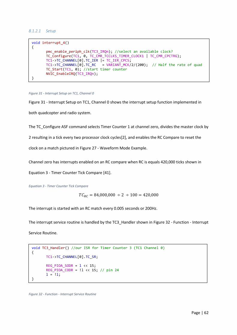
Page | 62
8.1.2.1 Setup
Figure 31 - Interrupt Setup on TC1, Channel 0
Figure 31 - Interrupt Setup on TC1, Channel 0 shows the interrupt setup function implemented in
both quadcopter and radio system.
The TC_Configure ASF command selects Timer Counter 1 at channel zero, divides the master clock by
2 resulting in a tick every two processor clock cycles[2], and enables the RC Compare to reset the
clock on a match pictured in Figure 27 - Waveform Mode Example.
Channel zero has interrupts enabled on an RC compare when RC is equals 420,000 ticks shown in
Equation 3 - Timer Counter Tick Compare [41].
Equation 3 - Timer Counter Tick Compare
𝑇𝐶𝑅𝐶 = 84,000,000 ÷ 2 ÷ 100 = 420,000
The interrupt is started with an RC match every 0.005 seconds or 200Hz.
The interrupt service routine is handled by the TC3_Handler shown in Figure 32 - Function - Interrupt
Service Routine.
Figure 32 - Function - Interrupt Service Routine
void interrupt_4() pmc_enable_periph_clk(TC3_IRQn); //select an available clock? TC_Configure(TC1, 0, TC_CMR_TCCLKS_TIMER_CLOCK1 | TC_CMR_CPCTRG); TC1->TC_CHANNEL[0].TC_IER |= TC_IER_CPCS; TC1->TC_CHANNEL[0].TC_RC = VARIANT_MCK/2/(200); // Half the rate of quad TC_Start(TC1, 0); //start timer counter NVIC_EnableIRQ(TC3_IRQn);
void TC3_Handler() //our ISR for Timer Counter 3 (TC1 Channel 0) TC1->TC_CHANNEL[0].TC_SR; REG_PIOA_SODR = l << 15; REG_PIOA_CODR = !l << 15; // pin 24 l = !l;

Page | 63
TC_SR resets the state of the interrupt and the Arduino Due pin 24 is toggled by writing a “1” to the
set or clear register.
8.2 Pseudo Scheduler Framework
As described in chapter 7.1 Pseudo Scheduler System, the system is configured as seen in Figure 33 -
Pseudo Scheduler Code. The function checks if “l” is true or not, which is modified during the timer
counter interrupt as shown in Figure 32 - Function - Interrupt Service Routine. If so, programOne() is
run until completion which then sets pin 26 high using the set register, and the program is kept in a
while loop until the next interrupt. The same is repeated for programTwo() with the only difference
being that, now, the “clock” pin is set low.
Figure 33 - Pseudo Scheduler Code
8.3 Inertial Measurement Unit
There are two parts to reading the absolute orientation data from the Bosch BMO055. Firstly, the
device needs to be initialised to relay the correct information. Secondly, the data must be pieced
together a byte at a time to read the Euler angles.
void loop() while(1) if (l) programOne(); REG_PIOD_SODR = 1 << 1; while (l) else programTwo(); REG_PIOD_SODR = 1 << 1; while (!l) REG_PIOD_CODR = 1 << 1;
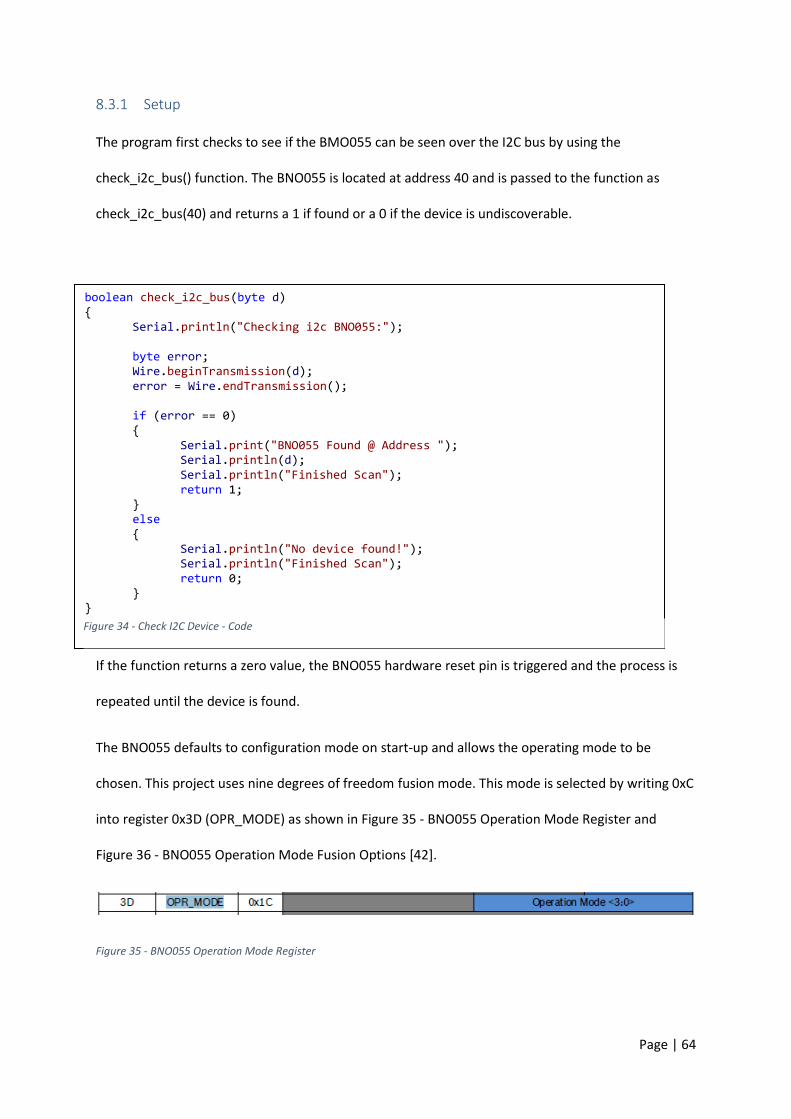
Page | 64
8.3.1 Setup
The program first checks to see if the BMO055 can be seen over the I2C bus by using the
check_i2c_bus() function. The BNO055 is located at address 40 and is passed to the function as
check_i2c_bus(40) and returns a 1 if found or a 0 if the device is undiscoverable.
If the function returns a zero value, the BNO055 hardware reset pin is triggered and the process is
repeated until the device is found.
The BNO055 defaults to configuration mode on start-up and allows the operating mode to be
chosen. This project uses nine degrees of freedom fusion mode. This mode is selected by writing 0xC
into register 0x3D (OPR_MODE) as shown in Figure 35 - BNO055 Operation Mode Register and
Figure 36 - BNO055 Operation Mode Fusion Options [42].
Figure 35 - BNO055 Operation Mode Register
boolean check_i2c_bus(byte d) Serial.println("Checking i2c BNO055:"); byte error; Wire.beginTransmission(d); error = Wire.endTransmission(); if (error == 0) Serial.print("BNO055 Found @ Address "); Serial.println(d); Serial.println("Finished Scan"); return 1; else Serial.println("No device found!"); Serial.println("Finished Scan"); return 0;
Figure 34 - Check I2C Device - Code

Page | 65
Figure 36 - BNO055 Operation Mode Fusion Options [42]
8.3.2 Reading Data
Absolute orientation Euler angles are stored in the BNO055 as a 16bit unsigned integers, one for
yaw, pitch and roll. I2C will only relay an 8bit unsigned integer at a time so the data needs to be read
and pieced together [42].
Figure 37 - BNO055 Read Data Code displays how six bytes starting at address 0x1A are read from
the BNO055. The first byte is the least significant byte of the yaw angle and needs to be combined
with the most significant byte to form the complete yaw angle. The process is repeated for roll and
pitch with register map for this process shown in Figure 38 - BNO055 Euler Values Registers [42].
void aquireEuler() Wire.beginTransmission(40); Wire.write(0x1A); // Read Euler Angles Wire.endTransmission(); Wire.requestFrom(40, 6); LSB = Wire.read(); MSB = Wire.read(); EUL_Heading = ((MSB << 8) | LSB); // YAW LSB = Wire.read(); MSB = Wire.read(); EUL_Roll = (((MSB << 8) | LSB)); // Roll LSB = Wire.read(); MSB = Wire.read(); EUL_Pitch = (((MSB << 8) | LSB)); // Pitch
Figure 37 - BNO055 Read Data Code
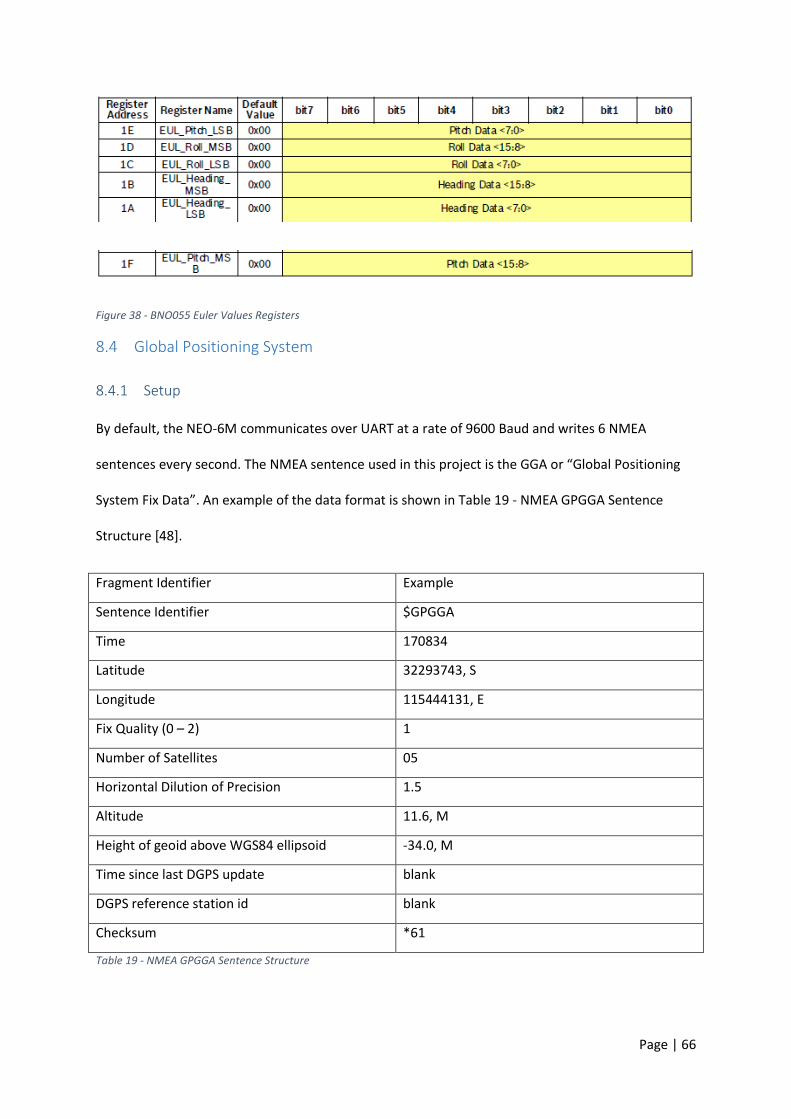
Page | 66
Figure 38 - BNO055 Euler Values Registers
8.4 Global Positioning System
8.4.1 Setup
By default, the NEO-6M communicates over UART at a rate of 9600 Baud and writes 6 NMEA
sentences every second. The NMEA sentence used in this project is the GGA or “Global Positioning
System Fix Data”. An example of the data format is shown in Table 19 - NMEA GPGGA Sentence
Structure [48].
Fragment Identifier Example
Sentence Identifier $GPGGA
Time 170834
Latitude 32293743, S
Longitude 115444131, E
Fix Quality (0 – 2) 1
Number of Satellites 05
Horizontal Dilution of Precision 1.5
Altitude 11.6, M
Height of geoid above WGS84 ellipsoid -34.0, M
Time since last DGPS update blank
DGPS reference station id blank
Checksum *61
Table 19 - NMEA GPGGA Sentence Structure
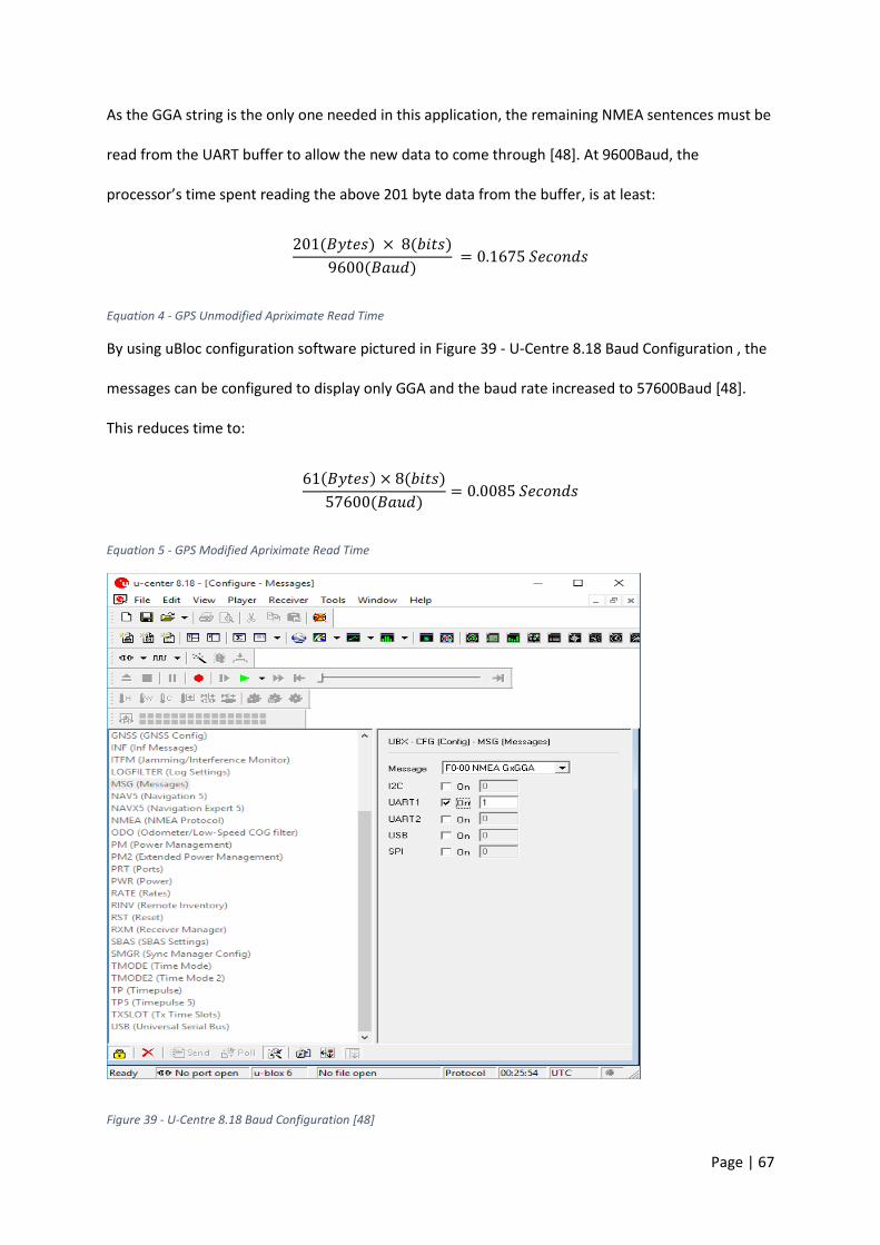
Page | 67
As the GGA string is the only one needed in this application, the remaining NMEA sentences must be
read from the UART buffer to allow the new data to come through [48]. At 9600Baud, the
processor’s time spent reading the above 201 byte data from the buffer, is at least:
201(𝐵𝑦𝑡𝑒𝑠) × 8(𝑏𝑖𝑡𝑠)
9600(𝐵𝑎𝑢𝑑) = 0.1675 𝑆𝑒𝑐𝑜𝑛𝑑𝑠
Equation 4 - GPS Unmodified Apriximate Read Time
By using uBloc configuration software pictured in Figure 39 - U-Centre 8.18 Baud Configuration , the
messages can be configured to display only GGA and the baud rate increased to 57600Baud [48].
This reduces time to:
61(𝐵𝑦𝑡𝑒𝑠) × 8(𝑏𝑖𝑡𝑠)
57600(𝐵𝑎𝑢𝑑)= 0.0085 𝑆𝑒𝑐𝑜𝑛𝑑𝑠
Equation 5 - GPS Modified Apriximate Read Time
Figure 39 - U-Centre 8.18 Baud Configuration [48]
Page | 68
8.4.2 Reading Data
The data is then read and stored into a 128 byte buffer and then searched for the 9th and 10th comma
character or ASCII value 44. The height above sea level is located between the two commas.
$GPGGA,091156.00,3229.62947,S,11544.68938,E,1,04,1.90,8.2,M,-31.1,M,,*51
Figure 40 - NMEA Example String
By including the C++ standard string library, the string to float function can be used to convert the
remaining portion of the NMEA string to a floating point number [48] [32]. The number is then used
to find the approximate sea level pressure (po) and is described in the next section. It is then saved
in a pseudo variable named: 𝐺𝑃𝑆_𝑎𝑙𝑡𝑖𝑡𝑢𝑑𝑒.
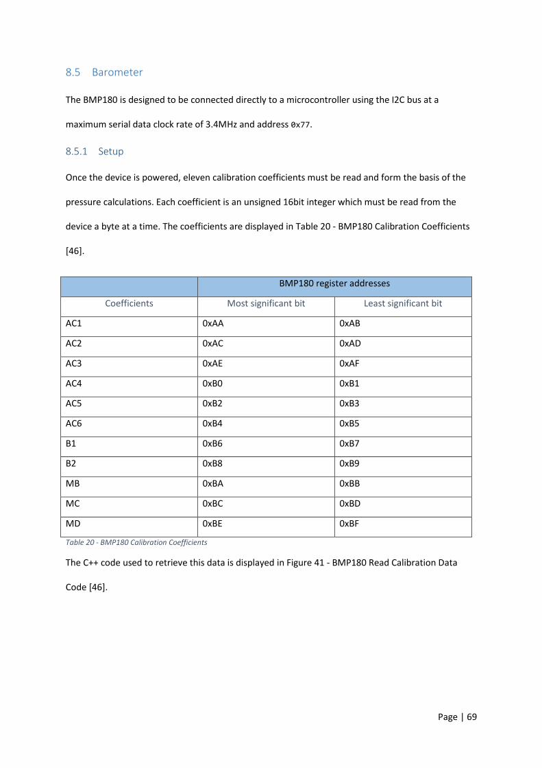
Page | 69
8.5 Barometer
The BMP180 is designed to be connected directly to a microcontroller using the I2C bus at a
maximum serial data clock rate of 3.4MHz and address 0x77.
8.5.1 Setup
Once the device is powered, eleven calibration coefficients must be read and form the basis of the
pressure calculations. Each coefficient is an unsigned 16bit integer which must be read from the
device a byte at a time. The coefficients are displayed in Table 20 - BMP180 Calibration Coefficients
[46].
BMP180 register addresses
Coefficients Most significant bit Least significant bit
AC1 0xAA 0xAB
AC2 0xAC 0xAD
AC3 0xAE 0xAF
AC4 0xB0 0xB1
AC5 0xB2 0xB3
AC6 0xB4 0xB5
B1 0xB6 0xB7
B2 0xB8 0xB9
MB 0xBA 0xBB
MC 0xBC 0xBD
MD 0xBE 0xBF
Table 20 - BMP180 Calibration Coefficients
The C++ code used to retrieve this data is displayed in Figure 41 - BMP180 Read Calibration Data
Code [46].

Page | 70
Figure 41 - BMP180 Read Calibration Data Code
void readCalibrationData() Wire1.beginTransmission(baro); Wire1.write(0xAA); Wire1.endTransmission(); Wire1.requestFrom(baro, 22); MSB = Wire1.read(); LSB = Wire1.read(); AC1 = ((MSB << 8) | LSB); MSB = Wire1.read(); LSB = Wire1.read(); AC2 = ((MSB << 8) | LSB); MSB = Wire1.read(); LSB = Wire1.read(); AC3 = ((MSB << 8) | LSB); MSB = Wire1.read(); LSB = Wire1.read(); AC4 = ((MSB << 8) | LSB); MSB = Wire1.read(); LSB = Wire1.read(); AC5 = ((MSB << 8) | LSB); MSB = Wire1.read(); LSB = Wire1.read(); AC6 = ((MSB << 8) | LSB); MSB = Wire1.read(); LSB = Wire1.read(); _B1 = ((MSB << 8) | LSB); MSB = Wire1.read(); LSB = Wire1.read(); _B2 = ((MSB << 8) | LSB); MSB = Wire1.read(); LSB = Wire1.read(); MB = ((MSB << 8) | LSB); MSB = Wire1.read(); LSB = Wire1.read(); MC = ((MSB << 8) | LSB); MSB = Wire1.read(); LSB = Wire1.read(); MD = ((MSB << 8) | LSB);
Page | 71
8.5.2 Reading Data
Before the data can be calculated, the uncompensated temperature and pressure values are read in
the same fashion as the calibration coefficients.
By writing 0x2E in to register 0xF4, the uncompensated temperature is read from the following
registers and pieced together by the following pseudo code:
UT = MSB << 8 + LSB
Pressure is read as an unsigned 19bit integer by writing 0x34 into register 0xF4 and reading from the
following registers and concatenating the values.
It is then combined with the following pseudo code:
UP = (MSB << 16 + LSB << 8 + XLSB) >> 5
After retrieving the uncompensated data, true temperature and pressure can be calculated by
pseudo code presented in Equation 6 - BMP180 True Temperature Pseudo Code [42].
𝑋1 = (𝑈𝑇 − 𝐴𝐶6) × 𝐴𝐶5 ⁄ 2^15
𝑋2 = (𝑀𝐶 × 2^11) ⁄ (𝑋1 + 𝑀𝐷)
𝐵5 = 𝑋1 + 𝑋2
𝑇 = ((𝐵5 + 8)) ⁄ 2^4
Equation 6 - BMP180 True Temperature Pseudo Code
True pressure is then calculated as shown in Equation 7 - BMP180 True Pressure Pseudo Code.
𝐵6 = 𝐵5 − 4000
𝑋1 = ((𝐵2 × ((𝐵6 × 𝐵6 ) ⁄ 2^12 ))) ⁄ 2^11
𝑋2 = 𝐴𝐶2 × 𝐵6 ⁄ 2^11
𝑋3 = 𝑋1 + 𝑋2
𝐵3 = (((((𝐿𝑜𝑛𝑔)𝐴𝐶1 × 4 + 𝑋3) ≪ 3) + 2 )) ⁄ 4
Page | 72
𝑋1 = 𝐴𝐶3 × 𝐵6 ⁄ 2^19
𝑋2 = (𝐵1 × (𝐵6 × 𝐵6 ≫ 12)) ≫ 16
𝑋3 = ((𝑋1 + 𝑋2) + 2) ≫ 2
𝐵4 = 𝐴𝐶4 × (𝑢𝑛𝑠𝑖𝑔𝑛𝑒𝑑 𝑙𝑜𝑛𝑔)(𝑋3 + 32768) ≫ 15
𝐵7 = ((𝑢𝑛𝑠𝑖𝑔𝑛𝑒𝑑 𝑙𝑜𝑛𝑔)𝑈𝑃 − 𝐵3) × (50000 ≫ 3)
𝑖𝑓(𝐵7 < 0𝑥80000000) 𝑝 = ((𝐵7 × 2))/𝑏4𝑒𝑙𝑠𝑒𝑝 = (𝐵7/𝐵4) × 2
𝑋1 = (𝑝 ≫ 8) × (𝑝 ≫ 8)
𝑋1 = (𝑋1 × 3038) ≫ 16
𝑋2 = (−7357 × 𝑝) ≫ 16
𝑝 = 𝑝 + (𝑋1 + 𝑋2 + 3791) ≫ 4
Equation 7 - BMP180 True Pressure Pseudo Code
Before the altitude can be calculated, the approximate sea level pressure must first be calculated to
avoid error as shown in Equation 8 - BMP180 Sea Level Pseudo Code [42].
𝑝_𝑜 = 𝑝/〖(1 − (𝐺𝑃𝑆_𝑎𝑙𝑡𝑖𝑡𝑢𝑑𝑒)/44330)〗^5.255
Equation 8 - BMP180 Sea Level Pseudo Code
Altitude is then calculated from the equation shown in Equation 9 - BMP180 Altitude Pseudo Code.
𝐴𝑙𝑡𝑖𝑡𝑢𝑑𝑒 = 44330 × (1 − 〖(𝑝/𝑝_𝑜 )〗^(1/5.255))
Equation 9 - BMP180 Altitude Pseudo Code
8.6 Wireless Communications
This section shows how the XBee radio is setup in the project and how the data is read. XBee radios
are configured from factory to be easy to use with almost any hardware with a serial interface. This
however limits the radios data throughput and some settings need to be programmed to maximise
the device’s functionality [49] [50].
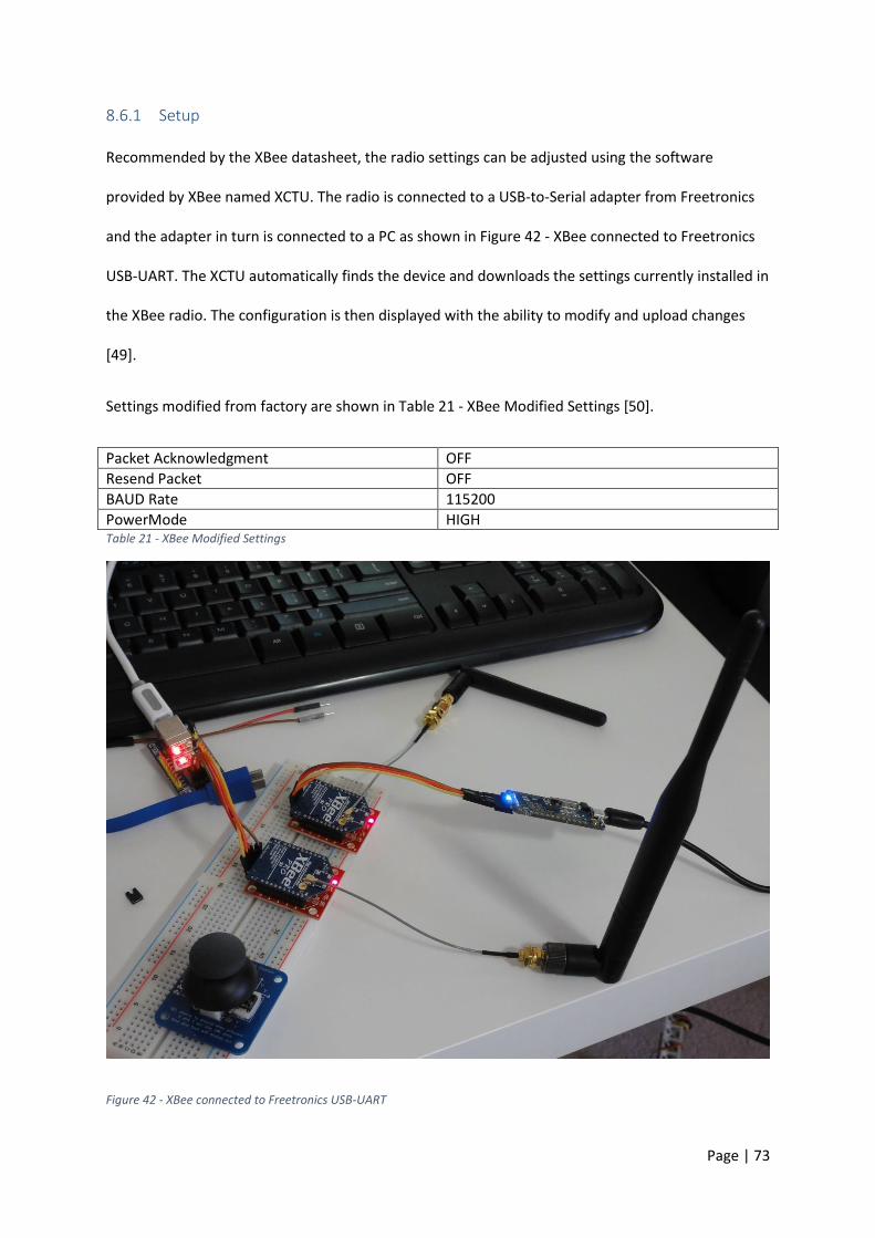
Page | 73
8.6.1 Setup
Recommended by the XBee datasheet, the radio settings can be adjusted using the software
provided by XBee named XCTU. The radio is connected to a USB-to-Serial adapter from Freetronics
and the adapter in turn is connected to a PC as shown in Figure 42 - XBee connected to Freetronics
USB-UART. The XCTU automatically finds the device and downloads the settings currently installed in
the XBee radio. The configuration is then displayed with the ability to modify and upload changes
[49].
Settings modified from factory are shown in Table 21 - XBee Modified Settings [50].
Packet Acknowledgment OFF
Resend Packet OFF
BAUD Rate 115200
PowerMode HIGH Table 21 - XBee Modified Settings
Figure 42 - XBee connected to Freetronics USB-UART
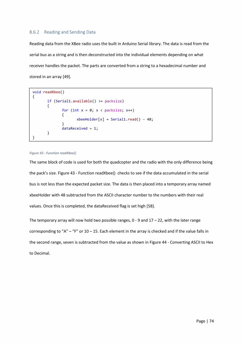
Page | 74
8.6.2 Reading and Sending Data
Reading data from the XBee radio uses the built in Arduino Serial library. The data is read from the
serial bus as a string and is then deconstructed into the individual elements depending on what
receiver handles the packet. The parts are converted from a string to a hexadecimal number and
stored in an array [49].
Figure 43 - Function readXbee()
The same block of code is used for both the quadcopter and the radio with the only difference being
the pack’s size. Figure 43 - Function readXbee() checks to see if the data accumulated in the serial
bus is not less than the expected packet size. The data is then placed into a temporary array named
xbeeHolder with 48 subtracted from the ASCII character number to the numbers with their real
values. Once this is completed, the dataReceived flag is set high [58].
The temporary array will now hold two possible ranges, 0 - 9 and 17 – 22, with the later range
corresponding to “A” – “F” or 10 – 15. Each element in the array is checked and if the value falls in
the second range, seven is subtracted from the value as shown in Figure 44 - Converting ASCII to Hex
to Decimal.
void readXbee() if (Serial1.available() >= packsize) for (int x = 0; x < packsize; x++) xbeeHolder[x] = Serial1.read() - 48; dataReceived = 1;
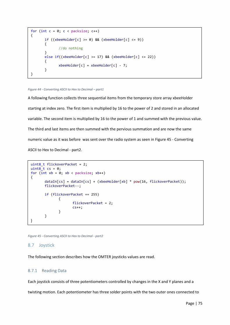
Page | 75
Figure 44 - Converting ASCII to Hex to Decimal – part1
A following function collects three sequential items from the temporary store array xbeeHolder
starting at index zero. The first item is multiplied by 16 to the power of 2 and stored in an allocated
variable. The second item is multiplied by 16 to the power of 1 and summed with the previous value.
The third and last items are then summed with the pervious summation and are now the same
numeric value as it was before was sent over the radio system as seen in Figure 45 - Converting
ASCII to Hex to Decimal - part2.
Figure 45 - Converting ASCII to Hex to Decimal - part2
8.7 Joystick
The following section describes how the OMTER joysticks values are read.
8.7.1 Reading Data
Each joystick consists of three potentiometers controlled by changes in the X and Y planes and a
twisting motion. Each potentiometer has three solder points with the two outer ones connected to
for (int c = 0; c < packsize; c++) if ((xbeeHolder[c] >= 0) && (xbeeHolder[c] <= 9)) //do nothing else if((xbeeHolder[c] >= 17) && (xbeeHolder[c] <= 22)) xbeeHolder[c] = xbeeHolder[c] - 7;
uint8_t flickoverPacket = 2; uint8_t cs = 0; for (int xb = 0; xb < packsize; xb++) dataIn[cs] = dataIn[cs] + (xbeeHolder[xb] * pow(16, flickoverPacket)); flickoverPacket--; if (flickoverPacket == 255) flickoverPacket = 2; cs++;
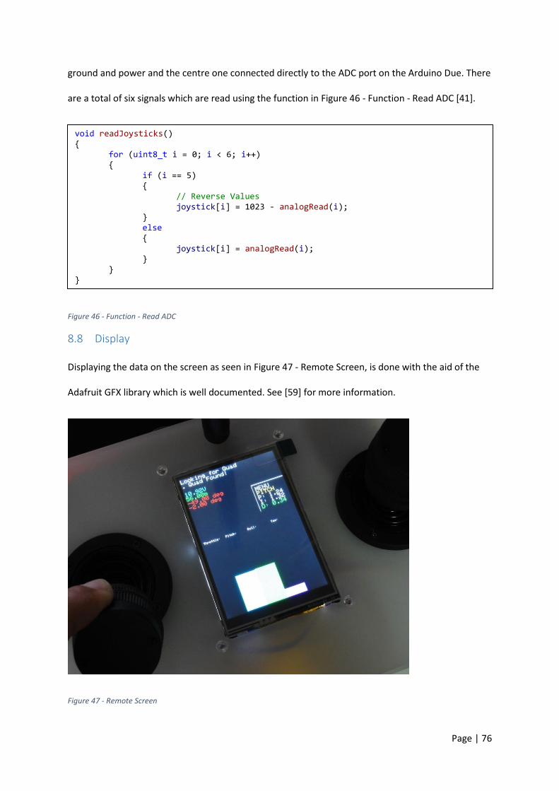
Page | 76
ground and power and the centre one connected directly to the ADC port on the Arduino Due. There
are a total of six signals which are read using the function in Figure 46 - Function - Read ADC [41].
Figure 46 - Function - Read ADC
8.8 Display
Displaying the data on the screen as seen in Figure 47 - Remote Screen, is done with the aid of the
Adafruit GFX library which is well documented. See [59] for more information.
Figure 47 - Remote Screen
void readJoysticks() for (uint8_t i = 0; i < 6; i++) if (i == 5) // Reverse Values joystick[i] = 1023 - analogRead(i); else joystick[i] = analogRead(i);

Page | 77
8.9 Voltage Divider
When designing the voltage divider, the requirements were minimal current draw with the output
never reaching above 3.3V. Maximum current is assumed at 1mA with the worst case input voltage
as 12.6V. As resistors are not manufactured to exact values, the output is scaled to 80% of 3.3v
leading to a calculated value of 2.64V. The resistors chosen for this divider, 8870Ω and 2320Ω, are
from the E96 series rated at 1%.
8.10 SD Card Module
The SD card module is connected by an SPI interface. During the remote start-up, the SD card is
checked for a text file named PID.txt. Inside this file, the PID coefficients are stored for all PID loops.
They are read by the remote with the code shown in Figure 48 - SD Card Read PID Values, and sent
to the quadcopter [38].
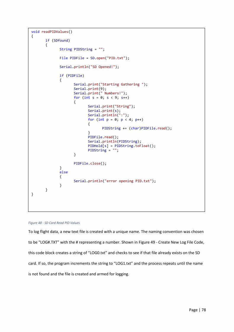
Page | 78
Figure 48 - SD Card Read PID Values
To log flight data, a new text file is created with a unique name. The naming convention was chosen
to be “LOG#.TXT” with the # representing a number. Shown in Figure 49 - Create New Log File Code,
this code block creates a string of “LOG0.txt” and checks to see if that file already exists on the SD
card. If so, the program increments the string to “LOG1.txt” and the process repeats until the name
is not found and the file is created and armed for logging.
void readPIDValues() if (SDfound) String PIDString = ""; File PIDFile = SD.open("PID.txt"); Serial.println("SD Opened!"); if (PIDFile) Serial.print("Starting Gathering "); Serial.print(9); Serial.print(" Numbers!"); for (int s = 0; s < 9; s++) Serial.print("String"); Serial.print(s); Serial.println(":"); for (int p = 0; p < 4; p++) PIDString += (char)PIDFile.read(); PIDFile.read(); Serial.println(PIDString); PIDHold[s] = PIDString.toFloat(); PIDString = ""; PIDFile.close(); else Serial.println("error opening PID.txt");

Page | 79
Figure 49 - Create New Log File Code
The logging of data is done in a similar way as stated before, with the file created being written to a
log interval denoted by “lc” and then closed to ensure data retention and no loss of data in case of
power failure. This is shown in Figure 50 - Logging Data to SD Card Code [38].
Uint16_t fileinc = 0; while (logFileNotCreated) LogFileName = ”LOG” + String(fileinc) + ".txt"; LogFileName.toCharArray(txtLogFile, 10); if (SD.exists(txtLogFile)) fileinc++; else logFileNotCreated = 0;
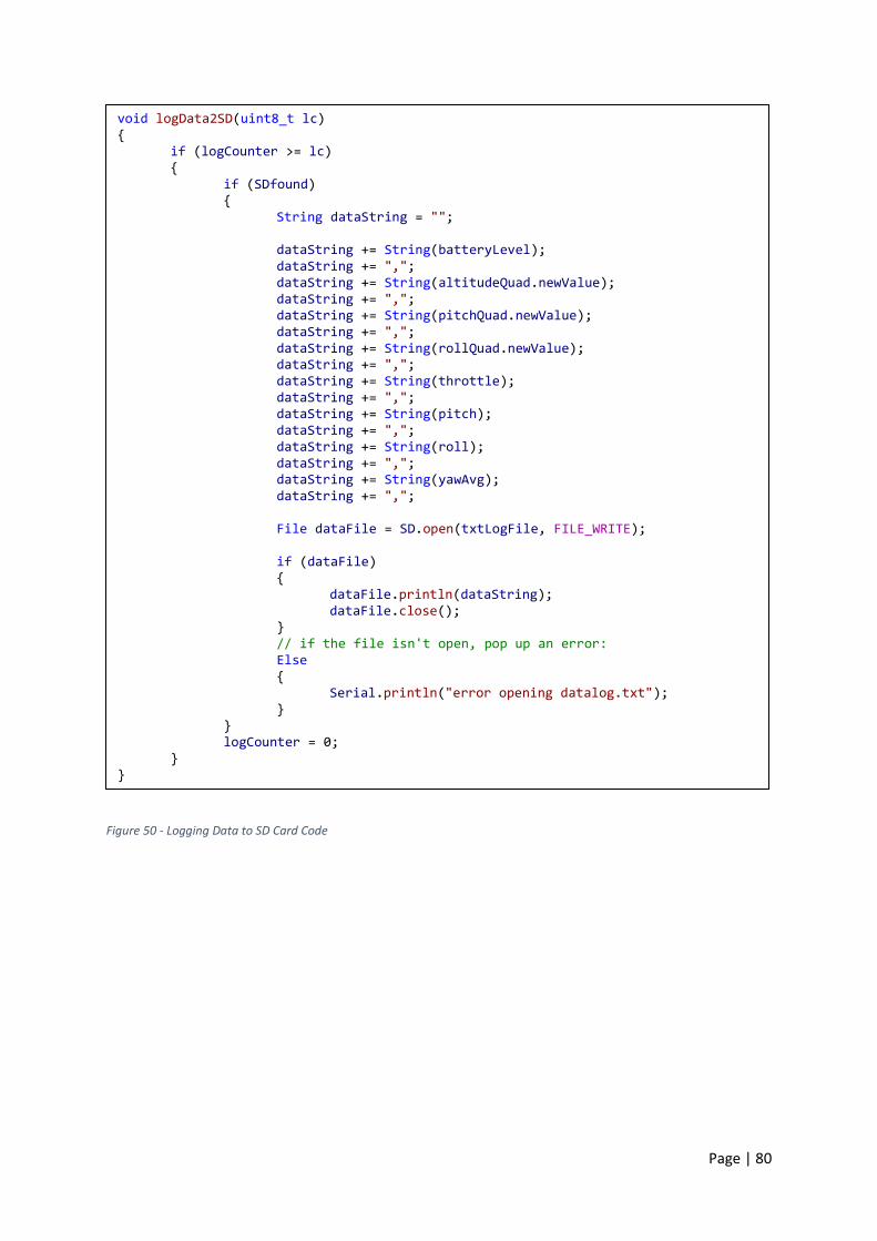
Page | 80
Figure 50 - Logging Data to SD Card Code
void logData2SD(uint8_t lc) if (logCounter >= lc) if (SDfound) String dataString = ""; dataString += String(batteryLevel); dataString += ","; dataString += String(altitudeQuad.newValue); dataString += ","; dataString += String(pitchQuad.newValue); dataString += ","; dataString += String(rollQuad.newValue); dataString += ","; dataString += String(throttle); dataString += ","; dataString += String(pitch); dataString += ","; dataString += String(roll); dataString += ","; dataString += String(yawAvg); dataString += ","; File dataFile = SD.open(txtLogFile, FILE_WRITE); if (dataFile)
dataFile.println(dataString); dataFile.close(); // if the file isn't open, pop up an error: Else
Serial.println("error opening datalog.txt"); logCounter = 0;
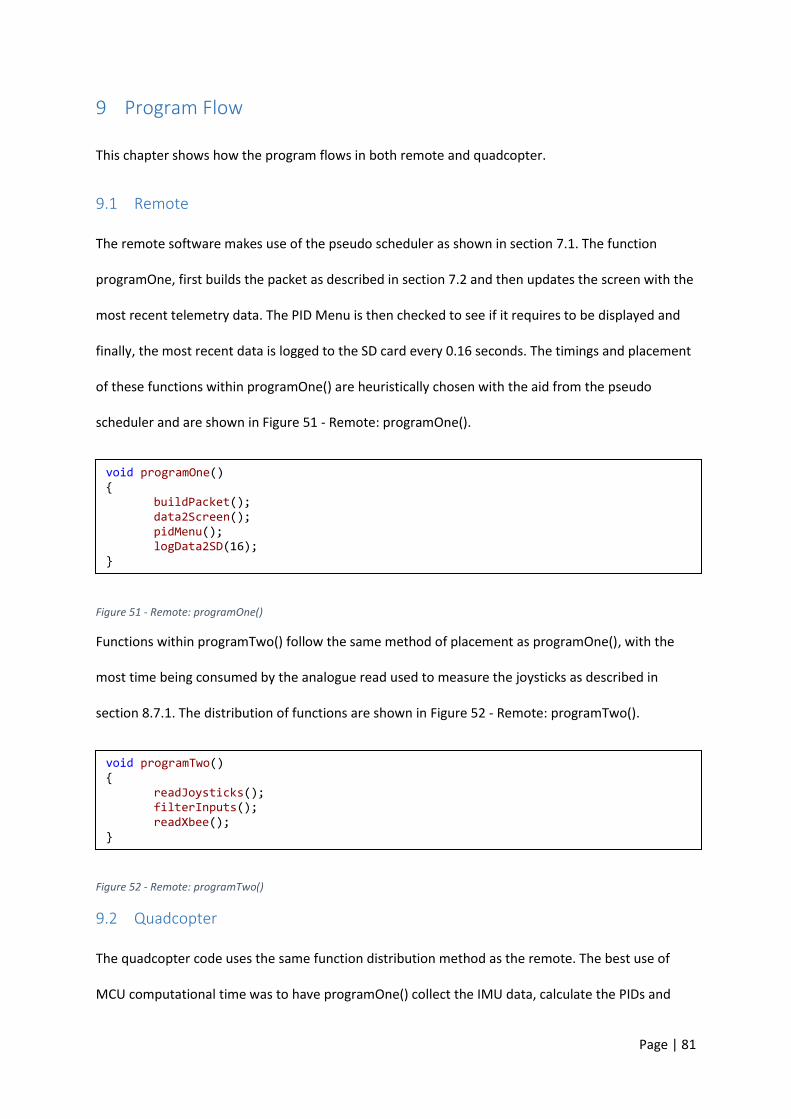
Page | 81
9 Program Flow
This chapter shows how the program flows in both remote and quadcopter.
9.1 Remote
The remote software makes use of the pseudo scheduler as shown in section 7.1. The function
programOne, first builds the packet as described in section 7.2 and then updates the screen with the
most recent telemetry data. The PID Menu is then checked to see if it requires to be displayed and
finally, the most recent data is logged to the SD card every 0.16 seconds. The timings and placement
of these functions within programOne() are heuristically chosen with the aid from the pseudo
scheduler and are shown in Figure 51 - Remote: programOne().
Figure 51 - Remote: programOne()
Functions within programTwo() follow the same method of placement as programOne(), with the
most time being consumed by the analogue read used to measure the joysticks as described in
section 8.7.1. The distribution of functions are shown in Figure 52 - Remote: programTwo().
Figure 52 - Remote: programTwo()
9.2 Quadcopter
The quadcopter code uses the same function distribution method as the remote. The best use of
MCU computational time was to have programOne() collect the IMU data, calculate the PIDs and
void programOne() buildPacket(); data2Screen(); pidMenu(); logData2SD(16);
void programTwo() readJoysticks(); filterInputs(); readXbee();

Page | 82
write the values with the appropriate sign to the ESCs. The battery is then checked and on every
second cycle, the barometer is read as shown in Figure 53 - Quadcopter : programOne().
Figure 53 - Quadcopter : programOne()
To obtain the remaining sensor data, programTwo() collects the hexadecimal string from the XBee
radio as described in Section 8.6.2 and maps the values according to throttle and the right stick
components. Telemetry is returned to the remote every 0.16 seconds and if the PID coefficients
have been updated, write the values for use in the next calculation. The function distribution is
shown in Figure 54 - Quadcopter: programTwo().
Figure 54 - Quadcopter: programTwo()
void programOne() aquireEuler(); runPIDs(); motorMix(); write2ESC(); batteryCheck();
readBarometer(2);
void programTwo() readXbee(); getThrottle(); getrightStick(); checkRadio(); returnData2(16); setPIDs();
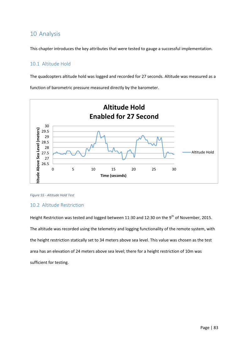
Page | 83
10 Analysis
This chapter introduces the key attributes that were tested to gauge a successful implementation.
10.1 Altitude Hold
The quadcopters altitude hold was logged and recorded for 27 seconds. Altitude was measured as a
function of barometric pressure measured directly by the barometer.
Figure 55 - Altitude Hold Test
10.2 Altitude Restriction
Height Restriction was tested and logged between 11:30 and 12:30 on the 9th of November, 2015.
The altitude was recorded using the telemetry and logging functionality of the remote system, with
the height restriction statically set to 34 meters above sea level. This value was chosen as the test
area has an elevation of 24 meters above sea level; there for a height restriction of 10m was
sufficient for testing.
26.5
27
27.5
28
28.5
29
29.5
30
0 5 10 15 20 25 30
Alt
itu
de
Ab
ove
Se
a Le
vel (
me
ters
)
Time (seconds)
Altitude Hold Enabled for 27 Second
Altitude Hold
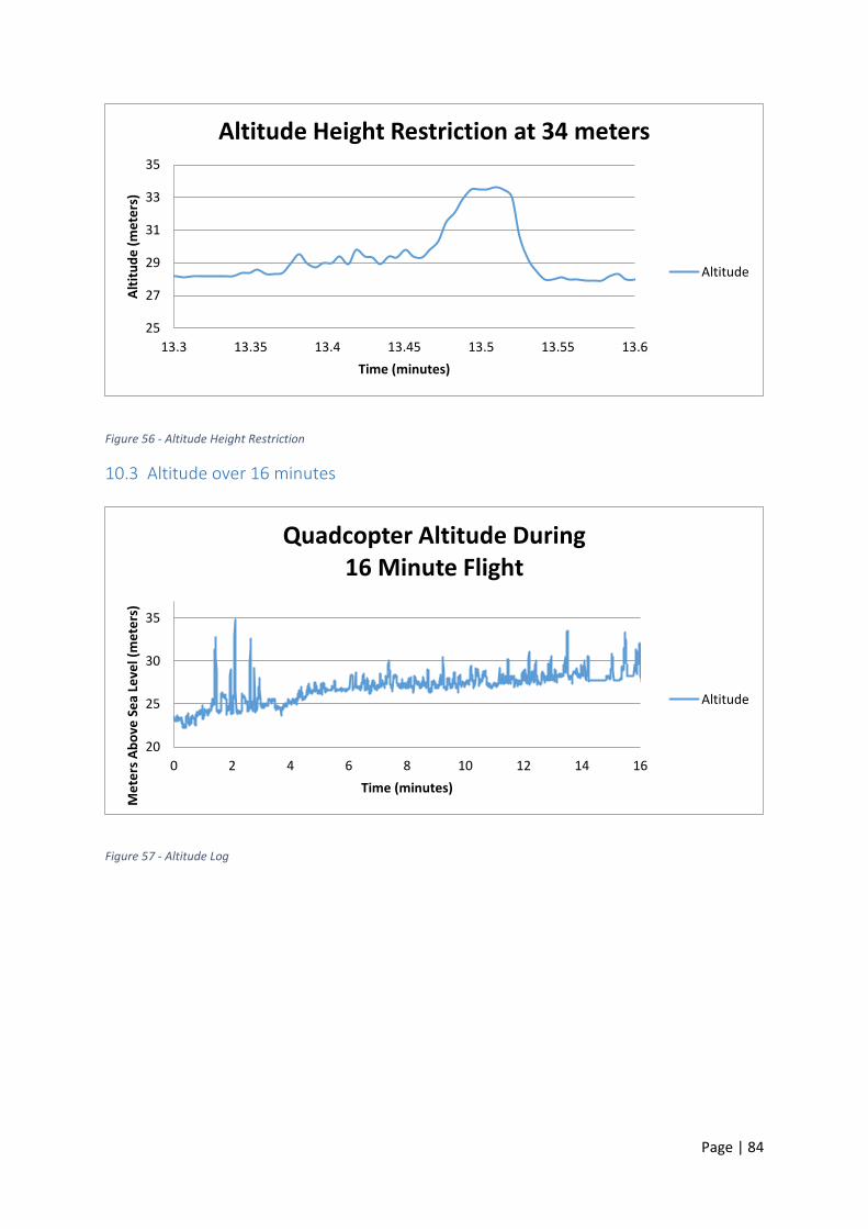
Page | 84
Figure 56 - Altitude Height Restriction
10.3 Altitude over 16 minutes
Figure 57 - Altitude Log
25
27
29
31
33
35
13.3 13.35 13.4 13.45 13.5 13.55 13.6
Alt
itu
de
(m
ete
rs)
Time (minutes)
Altitude Height Restriction at 34 meters
Altitude
20
25
30
35
0 2 4 6 8 10 12 14 16
Me
ters
Ab
ove
Se
a Le
vel (
me
ters
)
Time (minutes)
Quadcopter Altitude During 16 Minute Flight
Altitude
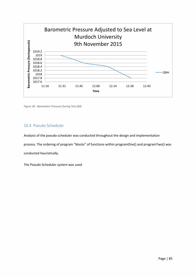
Page | 85
Figure 58 - Barometric Pressure During Test [60]
10.4 Pseudo Scheduler
Analysis of the pseudo scheduler was conducted throughout the design and implementation
process. The ordering of program “blocks” of functions within programOne() and programTwo() was
conducted heuristically.
The Pseudo Scheduler system was used
1017.61017.8
10181018.21018.41018.61018.8
10191019.2
11:16 11:31 11:45 12:00 12:14 12:28 12:43Bar
om
etr
ic P
ress
ure
(h
ect
op
asca
ls)
Time
Barometric Pressure Adjusted to Sea Level at Murdoch University 9th November 2015
QNH

Page | 86
Figure 59 - Pseudo Scheduler Performance
10.5 Battery Monitoring
Battery voltage was measured by scaling down with a voltage divider circuit so the MCU could read
it without permanent damage to the ADC. A voltage was applied to the circuit and checked with a
Rigol DS2072A [61] oscilloscope and compared to the value displayed on the telemetry screen.
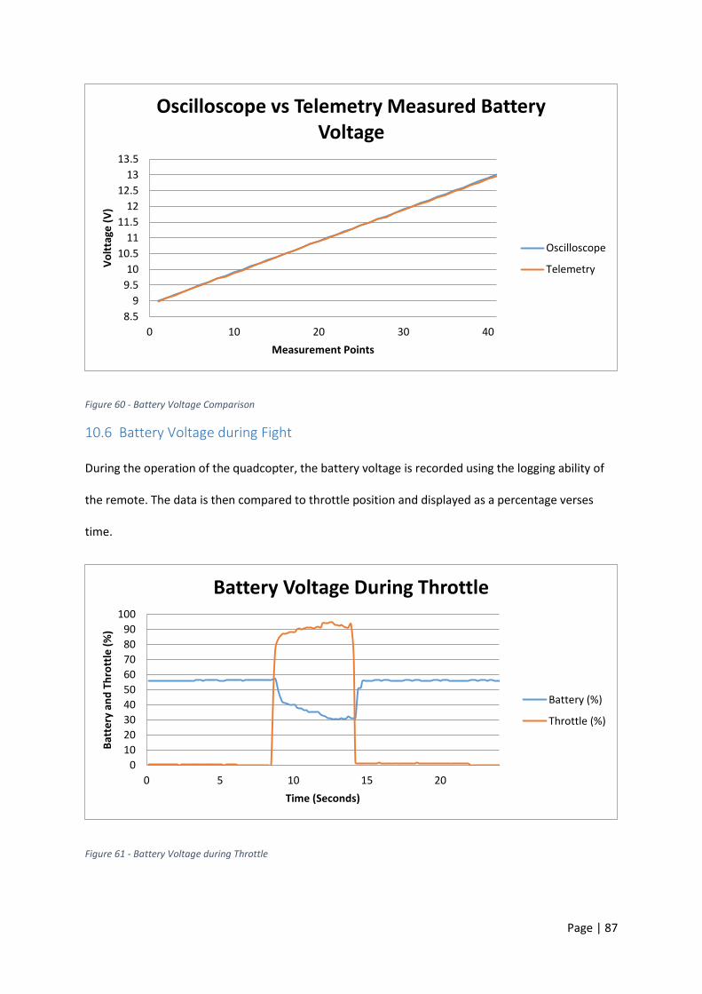
Page | 87
Figure 60 - Battery Voltage Comparison
10.6 Battery Voltage during Fight
During the operation of the quadcopter, the battery voltage is recorded using the logging ability of
the remote. The data is then compared to throttle position and displayed as a percentage verses
time.
Figure 61 - Battery Voltage during Throttle
8.5
9
9.5
10
10.5
11
11.5
12
12.5
13
13.5
0 10 20 30 40
Vo
ltta
ge (
V)
Measurement Points
Oscilloscope vs Telemetry Measured Battery Voltage
Oscilloscope
Telemetry
0
10
20
30
40
50
60
70
80
90
100
0 5 10 15 20
Bat
tery
an
d T
hro
ttle
(%
)
Time (Seconds)
Battery Voltage During Throttle
Battery (%)
Throttle (%)

Page | 88
11 Discussion
Data was logged over a 16 minute time frame with the PID coefficients initially started at zero; this
data set is shown in Figure 57 - Altitude Log The first four minutes consisted of tuning these
parameters until the quadcopter was observed to behave as a pre-tuned commercial product is
expected to. The coefficients were found heuristically and became the default start-up values the
next time the quadcopter was flown. This confirmed the update, storage and retrieval process of
these coefficients to and from the radio SD card system.
Tuning the quadcopter PID values in the field provided a faster method of achieving flight. The
operator, with enough knowledge in control theory, can experiment with new components and
weights and adjust these values appropriately with instant feedback.
The altitude data logged in Figure 55 - Altitude Hold Test, was logged on the 9th of November 2015 in
the middle of a large public oval. The quadcopter was subject to disturbances from wind and
required intervention to reduce the chance of a crash. Altitude hold requires the operator to achieve
a steady hover manually before switching modes. However, the results show that altitude hold was
not achievable during this test. Analysis of barometer data shows that even with a moving average
filter, the noise is notably present. Noise and an incorrectly tuned PID are the likely cause of altitude
hover instability.
The height restriction as shown in Figure 56 - Altitude Height Restriction, clearly shows height being
restricted to below 34 meters as long as this limit is approached carefully. During the PID tuning
phase, the altitude restriction appeared to have allowed an overshoot of 0.8 meters as shown in
Figure 57 - Altitude Log. This is the result of the throttle being reduced and making the quadcopter
unstable. Countering this, the PID’s governing roll, pitch and yaw may have contributed to the slight
increase in altitude. As the values are tuned, the quadcopter does not exceed the 34m restriction
imposed.
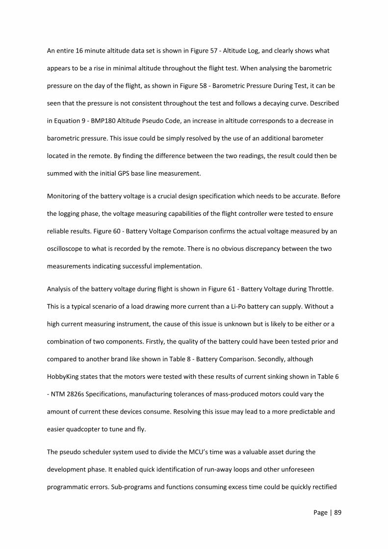
Page | 89
An entire 16 minute altitude data set is shown in Figure 57 - Altitude Log, and clearly shows what
appears to be a rise in minimal altitude throughout the flight test. When analysing the barometric
pressure on the day of the flight, as shown in Figure 58 - Barometric Pressure During Test, it can be
seen that the pressure is not consistent throughout the test and follows a decaying curve. Described
in Equation 9 - BMP180 Altitude Pseudo Code, an increase in altitude corresponds to a decrease in
barometric pressure. This issue could be simply resolved by the use of an additional barometer
located in the remote. By finding the difference between the two readings, the result could then be
summed with the initial GPS base line measurement.
Monitoring of the battery voltage is a crucial design specification which needs to be accurate. Before
the logging phase, the voltage measuring capabilities of the flight controller were tested to ensure
reliable results. Figure 60 - Battery Voltage Comparison confirms the actual voltage measured by an
oscilloscope to what is recorded by the remote. There is no obvious discrepancy between the two
measurements indicating successful implementation.
Analysis of the battery voltage during flight is shown in Figure 61 - Battery Voltage during Throttle.
This is a typical scenario of a load drawing more current than a Li-Po battery can supply. Without a
high current measuring instrument, the cause of this issue is unknown but is likely to be either or a
combination of two components. Firstly, the quality of the battery could have been tested prior and
compared to another brand like shown in Table 8 - Battery Comparison. Secondly, although
HobbyKing states that the motors were tested with these results of current sinking shown in Table 6
- NTM 2826s Specifications, manufacturing tolerances of mass-produced motors could vary the
amount of current these devices consume. Resolving this issue may lead to a more predictable and
easier quadcopter to tune and fly.
The pseudo scheduler system used to divide the MCU’s time was a valuable asset during the
development phase. It enabled quick identification of run-away loops and other unforeseen
programmatic errors. Sub-programs and functions consuming excess time could be quickly rectified
Page | 90
with less time spent debugging. Once the program timings were finalised, the pseudo scheduler
system clearly displayed large amounts of time that were unused as shown in Figure 59 - Pseudo
Scheduler . At the programs current state, the pseudo scheduler shows a major inefficient use of the
SAM3X8E based MCU with at least 70% of the processors time spent in idle. However, the program
was written to ensure CPU cycles were not wasted on inefficient code and makes good use of
hardware functions available as discussed in section 5.1.2 and 8.1, further reducing CPU cycles.
Page | 91
12 Recommendations and Future Improvements
Additional Barometer – An additional barometer installed on the remote could be used to counter
the rising altitude.
Real Time Operating System – A RTOS would make more efficient use of the MCUs computational
time.
Quadcopter Profiles – This would allow additional frame PID values to be saved and recalled
depending what the user is requesting.
Signal Filtering - Computational intensive filtering should be implemented to smooth out the
barometer noise allowing for a smoother auto hover.
Customisable joystick curves – This would allow the user to change the curves allowing more
customisation and a more controlled feel.
Page | 92
13 Conclusion
This project involved the design, construction and implementation of a novel quadcopter flight
controller and remote, to successfully fly an ‘X’ frame quadcopter. Starting with zero control
settings, a user can adjust and experiment with these settings to be able fly in less than five minutes.
The system can recall and use previous settings saved as well as log numerous flight telemetries for
analysis. Altitude hold would be much more effective with less noisy altitude data and another $10
barometer located in the remote to counter the changing barometric pressure throughout the day.
With abundant MCU time available, CPU intensive filtering can be implemented additionally to the
program without the risk of critical timings being displaced. This is simply not possible with some
flight controllers like the HobbyKing KK board stated in section 3.6.1. Telemetry previously offered
by high end devices is displayed to the user for quick battery health checks which should reduce the
amount of crashes due to insufficient battery power. Height restriction was implemented to ten
meters but was shown to provide the necessary functionality required with the full 123m limit easily
modified in the program code.

Page | 93
14 Appendix 4 – Copyright Permission
Aharon,
Thanks for writing.
You are free to use a still for your thesis. We will, however, require a licensing fee if you are to use this clip
for any commercial purposes.
Master File:
http://wpc.281e.edgecastcdn.net/80281E/viralhog/2015/Jan/8/ViralHog-dot-com-
firstdaydrone_1420764675.mp4
Best,
Brian Robinson
ViralHog, LLC
3701 Trakker Trail Ste 2J
Bozeman, MT 59718-9202 USA
+1 406.922.2588
Hi Aharon,
Thank you for contacting Texas Instruments. Your request has been received and Service Request number SR#1-1956173224 has been assigned to your inquiry.

Page | 94
The datasheet as well as the other document that you can download from our official website are open for general public.
You may use the the information in the datasheet as reference.
Best Regards,
**********
TEXAS INSTRUMENTS
Contact: www.ti.com/sc/apic
Internet Support: support.ti.com
Hello,
We appreciate your checking with us our copyrighted material/pictures from our website. Since the
kind of reproduction you described, could be considered as the type of permitted copyright “fair use”
no formal approval is required from Atmel. You may proceed with such described usage. We only ask
you to attribute source of material you use in your thesis.
Please refer to this link: http://www.atmel.com/About/legal.aspx
Thank you for your interest in Atmel products.
Regards,
Customer Service
Atmel Corporation
Page | 95
Corporate Headquarters
1600 Technology Drive
San Jose, CA 95110 USA
Page | 96
15 Bibliography
[1] Kross Blade, “www.krossblade.com,” Kross Blade, 2015. [Online]. Available:
http://www.krossblade.com/history-of-quadcopters-and-multirotors/. [Accessed 2015].
[2] Quadcopter Arena, “Quadcopter Arena,” Amazon.com, 2015. [Online]. Available:
http://quadcopterarena.com/. [Accessed November 2015].
[3] UNMANNED AIRCRAFT AND ROCKETS, “www.casa.gov.au,” 2002. [Online]. Available:
https://www.casa.gov.au/sites/g/files/net351/f/_assets/main/rules/1998casr/101/101c01.pdf?
v=1378480833. [Accessed 2015].
[4] RPAS Training and Solutions, “http://www.rpastraining.com.au/,” 6 August 2015. [Online].
Available: http://www.rpastraining.com.au/casr-101-uav-drone-legal-or-illegal.
[5] Z. Spanjer, “My first day with my drone,” YouTube, January 2015. [Online]. Available:
https://www.youtube.com/watch?v=VsHMjWORFvI. [Accessed 2015].
[6] T. BURROWS, “www.dailymail.co.uk,” The Mail on Sunday & Metro Media Group, January 2015.
[Online]. Available: http://www.dailymail.co.uk/news/article-2903719/Wading-Hilarious-
moment-panicked-drone-owner-jumps-freezing-lake-rescue-flawed-device-day-flying.html.
[Accessed November 2015].
[7] DJI, “Phantom 2,” Dji, 2015. [Online]. Available: https://www.dji.com/product/phantom-2.
[Accessed November 2015].
[8] R. Chatfield, “Vimeo,” Ryan Chatfield Images, October 2015. [Online]. Available:
https://vimeo.com/140156039. [Accessed 2015].
[9] K. E. G. Y. a. T. F. F. Tapesh Joshia, “Effects of Dissolved Transition Metals on the Electrochemical
Performance and SEI Growth in Lithium-Ion Batteries,” J. Electrochem. Soc, vol. 161, no. 12, p.
2016, 2014.
[10
]
L. Fried, “li-ion-and-lipoly-batteries,” Adafruit, [Online]. Available: https://learn.adafruit.com/li-
ion-and-lipoly-batteries/voltages. [Accessed 17 September 2015].
[11
]
S. Nejad, D. T. Gladwin and D. A. Stone, “Parameter Identification of Li-Po Batteries,” IECON
2014 - 40th Annual Conference of the IEEE Industrial Electronics Society, p. 7, 2013.
[12
]
W. Altmann, Practical Process Control for Engineers and Technicians, Newnes, 2005.
[13 K. M. Fauske, “Texample,” 23 November 2006. [Online]. Available:

Page | 97
] http://www.texample.net/tikz/examples/control-system-principles/ . [Accessed November
2015].
[14
]
CH Robotics LLC, “Understanding Euler Angles,” CHRobotics LLC, 2015. [Online]. Available:
http://www.chrobotics.com/library/understanding-euler-angles. [Accessed November 2015].
[15
]
Dantor, “Commons Wikimedia,” Wikimedia.org, 2015. [Online]. Available:
https://commons.wikimedia.org/wiki/File:Rollpitchyawplain.png . [Accessed November 2015].
[16
]
P. F. Eric M. Jones, “Gimbal Angles, Gimbal Lock, and a Fourth Gimbal for Christmas,” NASA, 29
April 2011. [Online]. Available: https://www.hq.nasa.gov/alsj/gimbals.html. [Accessed
November 2015].
[17
]
V. A. C. L. R. M. A. R. Andrea Alaimo, “PID Controller Applied to Hexacopter Flight,” Journal of
Intelligent & Robotic Systems, vol. 73, no. 1, pp. 261-270, 2014.
[18
]
H. P. Y. H. Hongbo Zhou, “Small unmanned helicopter flight controller design by use of,”
Proceedings of the 31st Chinese Control Conference, pp. 312 - 317, 2012.
[19
]
R. M. P. C. P. Poundsa, “Modelling and control of a large quadrotor robot,” Control Engineering
Practice, vol. 18, no. 7, p. 691–699, 2010.
[20
]
HobbyKing, “HobbyKing,” HobbyKing, 2015. [Online]. Available:
http://www.hobbyking.com/hobbyking/store/index.asp. [Accessed 2015].
[21
]
C. Schroeder, “Sturdy Quadcopter Build,” Instructables, 2015. [Online]. Available:
http://www.instructables.com/id/Sturdy-Quadcopter-Build/. [Accessed November 2015].
[22
]
AVR Atmel Corporation, “ATmega644/V,” 2012. [Online]. Available:
http://www.atmel.com/Images/doc2593.pdf. [Accessed November 2015].
[23
]
Guangzhou Walkera Technology CO, “Walkera.com,” Guangzhou Walkera Technology CO, 2015.
[Online]. Available: http://www.walkera.com/En/. [Accessed November 2015].
[24
]
Parrot SA, “Parrot.com,” Parrot SA, 2015. [Online]. Available:
http://www.parrot.com/au/products/ . [Accessed November 2015].
[25
]
senseFly Ltd, “sensefly.com,” senseFly Ltd, 2015. [Online]. Available:
https://www.sensefly.com/drones/exom.html. [Accessed November 2015].
[26
]
R. Salamun, “thequadcopterguy,” blogspot.com.au, 2015. [Online]. Available:
http://thequadcopterguy.blogspot.com.au/p/choosing-your-parts_23.html. [Accessed
November 2015].
[27
]
Y. Gao, “How much weight can a quadcopter lift?,” Quora, 10 October 2013. [Online]. Available:
https://www.quora.com/How-much-weight-can-a-quadcopter-lift. [Accessed November 2015].
[28 Britt, “Choosing Quadcopter Motors and Props,” Oddcopter, 6 February 2012. [Online].
Available: http://oddcopter.com/2012/02/06/choosing-quadcopter-motors-and-props/.
Page | 98
] [Accessed November 2015].
[29
]
Afro, “Arduino,” [Online]. Available: http://arduino-ua.com/docs/AfroESC30A.pdf. [Accessed 2
September 2015].
[30
]
http://copter.ardupilot.com/, “What is a MultiCopter and How Does it Work,” 2013. [Online].
Available: http://copter.ardupilot.com/wiki/introduction/what-is-a-multicopter-and-how-does-
it-work/.
[31
]
Atmel Corporation, “Embedded Software Solution for Atmel Flash MCUs,” Atmel, 2012. [Online].
Available: http://asf.atmel.com/docs/latest/. [Accessed 17 September 2015].
[32
]
A. Allain, “cprogramming,” 2011. [Online]. Available:
http://www.cprogramming.com/tutorial/c++-tutorial.html. [Accessed 17 September 2015].
[33
]
Wikipedia, “I²C,” Wikimedia Foundation, Inc., 17 September 2015. [Online]. Available:
https://en.wikipedia.org/wiki/I%C2%B2C. [Accessed 17 September 2015].
[34
]
M. Rouse, “UART (Universal Asynchronous Receiver/Transmitter),” TechTarget, February 2011.
[Online]. Available: http://whatis.techtarget.com/definition/UART-Universal-Asynchronous-
Receiver-Transmitter. [Accessed November 2015].
[35
]
B. McClure, “GIDS,” gids, July 2001. [Online]. Available: http://aprs.gids.nl/nmea/#gga.
[Accessed November 2015].
[36
]
Digi, “MODULES,” Digi, 2015. [Online]. Available: http://www.digi.com/products/xbee-rf-
solutions/modules. [Accessed November 2015].
[37
]
Ebay, “Ebay,” Ebay, 2015. [Online]. Available: www.ebay.com.au. [Accessed November 2015].
[38
]
Arduino, “Arduino,” Arduino, 2015. [Online]. Available: http://arduino.cc/. [Accessed November
2015].
[39
]
Altronics, “Arduino Dev Boards,” Altronics, 2015. [Online]. Available:
http://www.altronics.com.au/arduino/. [Accessed November 2015].
[40
]
Texas Instruments Incorporated, “Thin SOT23 1A Load Step-Down DC-DC Regulator,” Texas
Instruments Incorporated, 2015. [Online]. Available: http://www.ti.com/product/lm2734.
[Accessed November 2015].
[41
]
Atmel Corporation, “Atmel-11057-32-bit-Cortex-M3-Microcontroller-SAM3X-
SAM3A_Datasheet,” 23 March 2015. [Online]. Available: http://www.atmel.com/Images/Atmel-
11057-32-bit-Cortex-M3-Microcontroller-SAM3X-SAM3A_Datasheet.pdf.
[42
]
Bosch Sensortec GmbH, “BST-BNO055-DS000-12,” November 2014. [Online]. Available:
http://www.adafruit.com/datasheets/BST_BNO055_DS000_12.pdf.
[43 K. Townsend, “Adafruit_BNO055,” October 2015. [Online]. Available:
Page | 99
] https://github.com/adafruit/Adafruit_BNO055. [Accessed November 2015].
[44
]
Freescale Semiconductor, “Three Axis Low-g,” 2010. [Online]. Available:
https://cdn.shopify.com/s/files/1/0045/8932/files/MMA7361LC_datasheet.pdf?100494.
[Accessed November 2015].
[45
]
InvenSense, “MPU-9250,” 17 Janurary 2014. [Online]. Available:
http://43zrtwysvxb2gf29r5o0athu.wpengine.netdna-cdn.com/wp-
content/uploads/2015/02/MPU-9250-Datasheet.pdf. [Accessed November 2015].
[46
]
Bosch Sensortec GmbH, “BST-BMP180-DS000-12,” 7 May 2015. [Online]. Available: http://ae-
bst.resource.bosch.com/media/products/dokumente/bmp180/BST-BMP180-DS000-12~1.pdf.
[47
]
A. Garratt, “Cheap GPS module,” blogspot.com.au, 3 March 2014. [Online]. Available:
http://nerdsville.blogspot.com.au/2014/03/cheap-gps-module.html. [Accessed November
2015].
[48
]
u-blox AG, “NEO-6 series,” 2011. [Online]. Available: https://www.u-
blox.com/sites/default/files/products/documents/NEO-6_DataSheet_%28GPS.G6-HW-
09005%29.pdf?utm_source=en%2Fimages%2Fdownloads%2FProduct_Docs%2FNEO-
6_DataSheet_%28GPS.G6-HW-09005%29.pdf. [Accessed November 2015].
[49
]
Digi International Inc, “XBee®/XBee-PRO® RF Modules,” 2009. [Online]. Available:
https://www.sparkfun.com/datasheets/Wireless/Zigbee/XBee-Datasheet.pdf.
[50
]
Digi International Inc, “digi.com,” 2015. [Online]. Available:
http://www.digi.com/pdf/ds_xbeemultipointmodules.pdf. [Accessed November 2015].
[51
]
Yueqing Omter Electronic & Technology Co, “3 axis joystick OM300B-M3,” Yueqing Omter
Electronic & Technology Co, 2014. [Online]. Available: http://www.omter-tyxn.com/3-axis-
joystick-OM300B-M3.html. [Accessed November 2015].
[52
]
Adafruit, “Adafruit 3.5" 320x480 Color TFT Touchscreen Breakout,” Adafruit, 2015. [Online].
Available: https://learn.adafruit.com/adafruit-3-5-color-320x480-tft-touchscreen-
breakout/overview. [Accessed November 2015].
[53
]
B. A. Ogunnaike, Process Dynamics, Modeling, and Control, New York: Oxford Universtiy Press,
1994.
[54
]
marcv81, “Quadcopter PID output,” Robotics Stackexchange, 13 May 2014. [Online]. Available:
http://robotics.stackexchange.com/questions/2964/quadcopter-pid-output. [Accessed
November 2015].
[55
]
O. Liang, “OscarLiang.net,” Custom Motor Mixing Multirotor, September 2015. [Online].
Available: http://blog.oscarliang.net/custom-motor-output-mix-quadcopter/. [Accessed
November 2015].
[56 iforce2d, “Motor mixing calculator,” iforce2d.net, 2015. [Online]. Available:

Page | 100
] https://www.iforce2d.net/mixercalc/. [Accessed November 2015].
[57
]
marcv81, “Robotics Stackexchange,” Stack Exchange Inc, 24 April 2014. [Online]. Available:
http://robotics.stackexchange.com/questions/2772/quadcopter-throttle-and-pid-mixing-to-
motor-speed. [Accessed November 2015].
[58
]
Columbia Space Shuttle Disaster. [Film]. 2015.
[59
]
Adafruit, “Github,” Adafruit, 2015. [Online]. Available: https://github.com/adafruit/Adafruit-
GFX-Library. [Accessed November 2015].
[60
]
Murduch University, “Murdoch University Weather Station,” 9 November 2015. [Online].
Available: http://wwwmet.murdoch.edu.au/downloads. [Accessed 10 November 2015].
[61
]
RIGOL Technologies Inc, “DS2000A | Series Digital Oscilloscopes,” RIGOL Technologies Inc, 2015.
[Online]. Available: http://www.rigolna.com/products/digital-oscilloscopes/ds2000a/. [Accessed
November 2015].
[62
]
Sailplane & Electric Modeler Magazine, “http://www.stefanv.com/,” 30 September 1997.
[Online]. Available: http://www.stefanv.com/electronics/escprimer.html.
[63
]
maxamps, “Lithium Polymer Charging/Discharging & Safety Information,” 6 August 2015.
[Online]. Available: http://www.maxamps.com/pdf/Lipo-Care.pdf.
[64
]
B. A. Ogunnaike and W. H. Ray, Process Dynamics, Modeling and Control, New York: Oxford
University Press, 1994.
[65
]
B. T. M. Leong, S. M. Low and M. P.-L. Ooi, “Low-Cost Microcontroller-based Hover Control
Design of a Quadcopter,” Elsevier Ltd, Selangor Darul Ehsan, Malaysia, 2012.
[66
]
A. L. L. Cunta, Mandurah, 2015.
[67
]
GIDS, “GPS - NMEA sentence information,” 23 July 2004. [Online]. Available:
http://aprs.gids.nl/nmea/. [Accessed 17 September 2015].
[68
]
Bosch, “Intelligent 9-axis absolute orientation sensor,” Intelligent 9-axis absolute orientation
sensor, 2014.