november, 2011 hisao izuchi ple technology center chiyoda...
TRANSCRIPT

Chatter of Safety Valvey
November, 2011
Hisao IZUCHIPLE Technology Center
Chiyoda Advanced Solutions Corporation
Copyright © 2011 Chiyoda Advanced Solutions Corporation. All Rights Reserved.

Contents
1. Purpose2. Experimental Results / Simulation Results / Stability Analysis3 Cl ifi i f I bili3. Classification of Instability
- Dynamic Instability (Acoustic Interaction)St ti I t bilit (P D D l t)- Static Instability (Pressure Drop Development)
4. Effect of PRV Inlet Pressure Drop5 Effect of PRV Outlet to Orifice Area Ratio5. Effect of PRV Outlet to Orifice Area Ratio6. Conclusion
Reference(1) H. IZUCHI, “Chatter of Safety Valve”, API Meeting, April 2008(2) H IZUCHI “Stability Analysis of Safety Valve” AIChE Spring Meeting April 2010(2) H. IZUCHI, Stability Analysis of Safety Valve , AIChE Spring Meeting, April 2010(3) V. Dossena, F. Marinoni, B. Paradiso, “Valve Size Influence on the Discharge Capacity
of Spring Loaded Safety Valves”, Paper 722, Valve World Conference 2007(4) D W S ll t d D W S “Fl C it d R f S f t R li f V l
1Copyright © 2011 Chiyoda Advanced Solutions Corporation. All Rights Reserved.
(4) D. W. Sallet and D. W. Somers, “Flow Capacity and Response of Safety Relief Valves to Saturated Water Flow”, Plant/Operation Progress, 4-4, 1985, 207-216

Purpose
Safety valve chatter would result in (1) Mechanical failure of the valve and related piping system (2) R li i fl d i d b i ffi i l(2) Reliving flow rate reduction caused by insufficient valve
opening due to chatter
Chiyoda had executed to study safety valve chatter for the following purposes:
(1) Investigate mechanism of chatter(2) How to prevent chatter
Study Program(1) Chatter test at a manufacturer experimental facility with air(2) Dynamic simulation (taking valve motion and pressure wave
propagation throughout inlet/outlet piping into account)(3) St bilit l i (th ti l i ti ti )
(3) Stability analysis (theoretical investigation)
2Copyright © 2011 Chiyoda Advanced Solutions Corporation. All Rights Reserved.

Experimental Facility
No Inlet PipeDisplacement
Meter
Safety Valve
Inlet Piping (5m)
Inlet Pipe Length is 1m
Vessel
3Copyright © 2011 Chiyoda Advanced Solutions Corporation. All Rights Reserved.
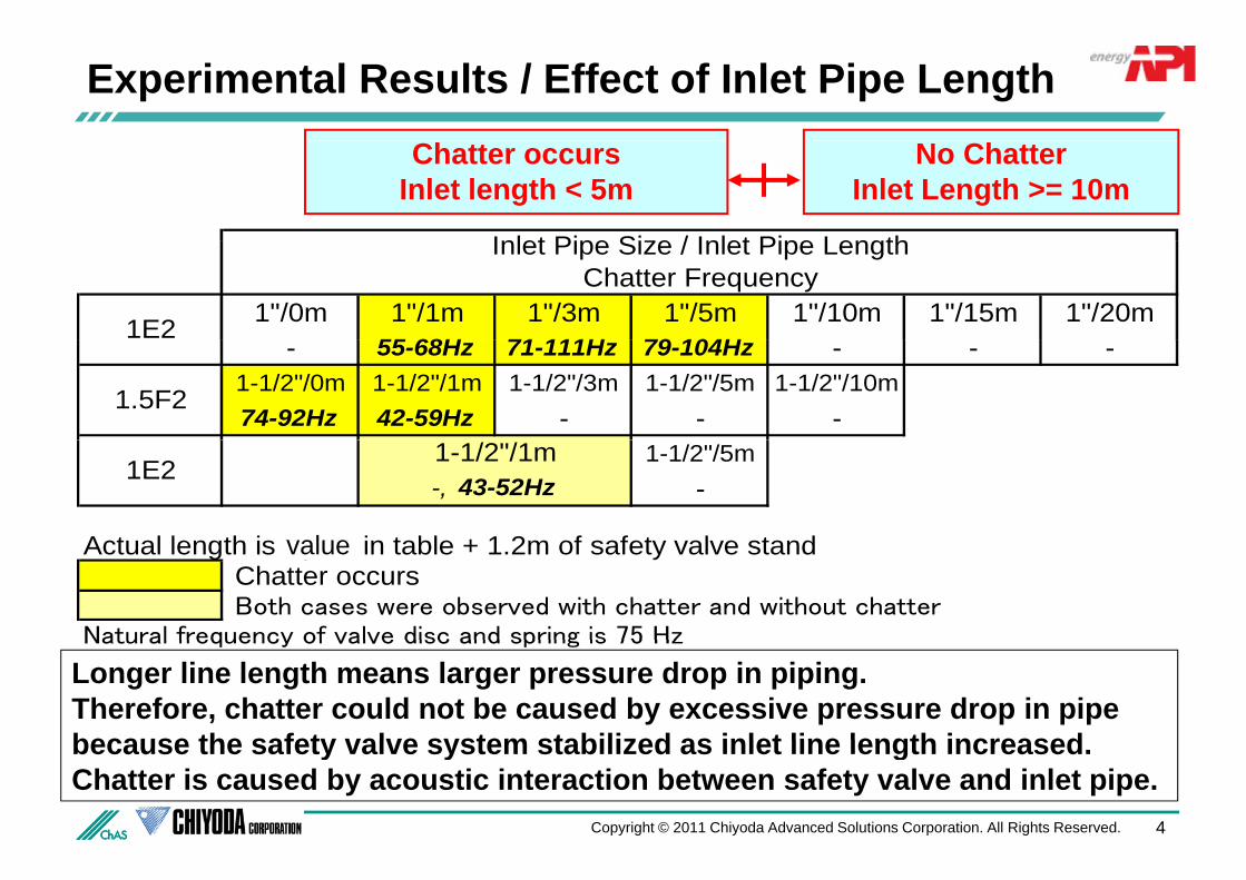
Experimental Results / Effect of Inlet Pipe Length
I l t Pi Si / I l t Pi L th
Chatter occursInlet length < 5m
No ChatterInlet Length >= 10m
1"/0m 1"/1m 1"/3m 1"/5m 1"/10m 1"/15m 1"/20m55 68H 71 111H 79 104H
1E2
Inlet Pipe Size / Inlet Pipe LengthChatter Frequency
- 55-68Hz 71-111Hz 79-104Hz - - -1-1/2"/0m 1-1/2"/1m 1-1/2"/3m 1-1/2"/5m 1-1/2"/10m74-92Hz 42-59Hz - - -
1.5F2
1-1/2"/5m-
A t l l th i fi i t bl + 1 2 f f t l t d
1E21-1/2"/1m-, 43-52Hz
lActual length is figure in table + 1.2m of safety valve stand Chatter occurs Both cases were observed with chatter and without chatter
Natural frequency of valve disc and spring is 75 Hz
value
Longer line length means larger pressure drop in piping.Therefore, chatter could not be caused by excessive pressure drop in pipe because the safety valve system stabilized as inlet line length increased
Natural frequency of valve disc and spring is 75 Hz
because the safety valve system stabilized as inlet line length increased.Chatter is caused by acoustic interaction between safety valve and inlet pipe.
4Copyright © 2011 Chiyoda Advanced Solutions Corporation. All Rights Reserved.

Dynamic Simulation Model
Safety ValveE ti f M ti f V l DiEquation of Motion for Valve DiscOrifice Flow Equation at NozzleFlow Equation at OutletMass Conservation in Valve Body
I l t / O tl t Pi iInlet / Outlet Piping(divided into several segments)
Equation of Mass ConservationEquation of Mass ConservationEquation of Motion for Gas FlowEquation for Energy ConservationEquation of State for Gas
Equation of State for Gas
5Copyright © 2011 Chiyoda Advanced Solutions Corporation. All Rights Reserved.

Simulation Results1E2 I l t 1”/1 N R d t O tl t
3.03.54.0
m)
1E2, Inlet : 1”/1m, No Reducer at Outlet
3.03.54.0
m)
1E2, Inlet : 1”/10m, No Reducer at Outlet71msec = Duration pressure wave propagates from safety valve to vessel and return back to safety valve
Experiment
Simulation
0 51.01.52.02.5
Lift
(mm
0 51.01.52.02.5
Lift
(mm
Oscillation is attenuated
0.00.5
0.0 0.1 0.2 0.3 0.4 0.5
L
Time (s)
0.00.5
0.0 0.1 0.2 0.3 0.4 0.5
L
Time (s)
Oscillation is attenuated
( )
3 54.0
1E2, Inlet : 0m, 1” Reducer at Outlet Interaction between valve disc motion and pressure wave propagation (acoustic phenomena) could cause instability
1.52.02.53.03.5
ft (m
m)
phenomena) could cause instability.
Simulation effectively indentifies safety valve instability caused by both of inlet
i i d ll l ifi i
0.00.51.0
0.0 0.1 0.2 0.3 0.4 0.5
Lift
Stability theory supports the safety valve instability caused by inlet pipe acoustics
piping and small outlet to orifice area ratio.
6Copyright © 2011 Chiyoda Advanced Solutions Corporation. All Rights Reserved.
Time (s) instability caused by inlet pipe acoustics.

Classification of Instability( ) D i I t bilit (A ti I t ti )(a) Dynamic Instability (Acoustic Interaction)
Opposite phase between lift and differential pressure though valve disc
Diff. Press.Valve Lift
2.14.0 Pa) 2.54.0 Pa)
1E2, Inlet : 1”/1m, No Reducer at Outlet(experimental results)
1E2, Inlet : 1”/10m, No Reducer at Outlet(experimental results)
Unstable
1 91.92.02.0
2.02.53.03.5
ress
. (M
P
(mm
)
1 0
1.5
2.0
1 52.02.53.03.5
ress
. (M
P
(mm
) Stable
1.71.81.81.9
0.00.51.01.5
0 00 0 10 0 20 0 30 0 40
Diff
. P
Lift
0.0
0.5
1.0
0.00.51.01.5
0 00 0 05 0 10 0 15 0 20
Diff
. P
Lift
0.00 0.10 0.20 0.30 0.40
Time (s)0.00 0.05 0.10 0.15 0.20
Time (s)- Caused by interaction between valve motion and pressure wave propagation at
inlet pipeinlet pipe- Relatively high frequency (determined by combination effect of acoustic natural
frequency and valve natural frequency)N l ti t i l t d
7Copyright © 2011 Chiyoda Advanced Solutions Corporation. All Rights Reserved.
- No relation to inlet pressure drop- Stable for longer length of safety valve inlet line due to attenuation effect
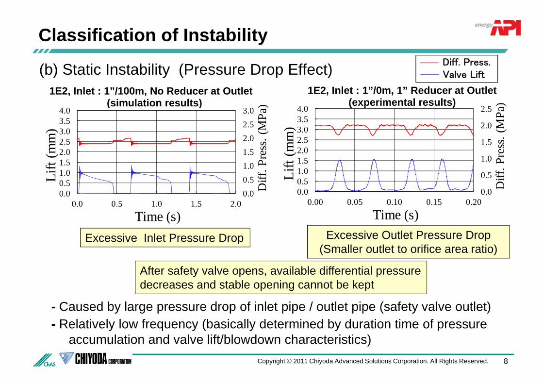
Classification of InstabilityDiff Press(b) Static Instability (Pressure Drop Effect)
) )
1E2, Inlet : 1”/100m, No Reducer at Outlet(simulation results)
1E2, Inlet : 1”/0m, 1” Reducer at Outlet(experimental results)
Diff. Press.Valve Lift
2.02.53.0
2.53.03.54.0
ss. (
MPa
)
mm
)
1.5
2.0
2.5
2 02.53.03.54.0
ss. (
MPa
)
mm
)
(simulation results) (experimental results)
0 00.51.01.5
0 00.51.01.52.0
Diff
. Pre
s
Lift
(m
0 0
0.5
1.0
0 00.51.01.52.0
Diff
. Pre
Lift
(m
0.00.00.0 0.5 1.0 1.5 2.0
Time (s)
0.00.00.00 0.05 0.10 0.15 0.20
Time (s)E cessi e Inlet Press re Drop Excessive Outlet Pressure Drop
After safety valve opens, available differential pressure
Excessive Inlet Pressure Drop Excessive Outlet Pressure Drop (Smaller outlet to orifice area ratio)
- Caused by large pressure drop of inlet pipe / outlet pipe (safety valve outlet)Relatively low frequency (basically determined by duration time of pressure
decreases and stable opening cannot be kept
8Copyright © 2011 Chiyoda Advanced Solutions Corporation. All Rights Reserved.
- Relatively low frequency (basically determined by duration time of pressure accumulation and valve lift/blowdown characteristics)

Effect of PRV Inlet Pressure Drop1 0 10%
Inlet Length 1m 10m 20m 50m(simulation)
100m(simulation)
1E2, Set 20barg, Blowdown = 10%
Inlet Press. Drop* 2.6% 3.8% 4.8% 9.2% 10.2%
Instability Unstable Stable Stable Stable UnstableInstability Unstable Stable Stable Stable Unstable
Cause of Instability
Dynamic / Acoustic - - -
Static / ExcessiveInstability (Press. Wave) Press. Drop
* : average figure at actual PRV lift
- PRV static instability due to excessive pressure drop occurs if inlet pressure drop- PRV static instability due to excessive pressure drop occurs if inlet pressure drop exceeds the blowdown of PRV. 3% rule for inlet pressure drop would be too much conservative.There is another mechanism of PRV instability dynamic instability caused by interaction- There is another mechanism of PRV instability, dynamic instability caused by interaction between valve motion and pressure wave propagation at inlet pipe (acoustic effect). This dynamic instability should be considered separately from inlet pressure drop.If i l t d ld b l th 3% fl it h ld b h k d t ki
9Copyright © 2011 Chiyoda Advanced Solutions Corporation. All Rights Reserved.
- If inlet pressure drop would be larger than 3%, flow capacity should be checked taking both effects of pressure drop and PRV lift reduce into account.
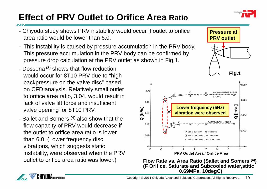
Effect of PRV Outlet to Orifice Area RatioChiyoda study shows PRV instability would occur if outlet to orifice P t- Chiyoda study shows PRV instability would occur if outlet to orifice area ratio would be lower than 6.0.
- This instability is caused by pressure accumulation in the PRV body. Thi l ti i th PRV b d b fi d b
Pressure atPRV outlet
This pressure accumulation in the PRV body can be confirmed by pressure drop calculation at the PRV outlet as shown in Fig.1.
Fig 1- Dossena (3) shows that flow reduction
Fig.1would occur for 8T10 PRV due to “high backpressure on the valve disc” based on CFD analysis. Relatively small outlet t ifi ti 3 04 ld lt i
[ft3 /s
]
[m3 /s
]
to orifice area ratio, 3.04, would result in lack of valve lift force and insufficient valve opening for 8T10 PRV. Lower frequency (5Hz)
vibration were observed
Q [ Q- Sallet and Somers (4) also show that the
flow capacity of PRV would decrease if the outlet to orifice area ratio is lower th 6 0 (L f di
PRV Outlet Area / Orifice Area
than 6.0. (Lower frequency disc vibrations, which suggests static instability, were observed when the PRV outlet to orifice area ratio was lower ) (4)
10Copyright © 2011 Chiyoda Advanced Solutions Corporation. All Rights Reserved.
outlet to orifice area ratio was lower.) Flow Rate vs. Area Ratio (Sallet and Somers (4))(F Orifice, Saturate and Subcooled water,stitic
0.69MPa, 10degC)
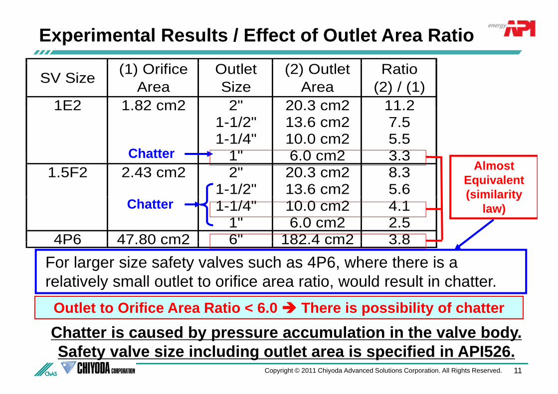
Experimental Results / Effect of Outlet Area Ratio
SV Size (1) OrificeArea
OutletSize
(2) OutletArea
Ratio(2) / (1)
1E2 1 82 cm2 2" 20 3 cm2 11 21E2 1.82 cm2 2 20.3 cm2 11.21-1/2" 13.6 cm2 7.51-1/4" 10.0 cm2 5.5
1" 6 0 2 3 3Chatter 1" 6.0 cm2 3.31.5F2 2.43 cm2 2" 20.3 cm2 8.3
1-1/2" 13.6 cm2 5.6
ChatterAlmost
Equivalent(similarity
1-1/4" 10.0 cm2 4.11" 6.0 cm2 2.5
4P6 47 80 cm2 6" 182 4 cm2 3 8
Chatter(similarity
law)
4P6 47.80 cm2 6 182.4 cm2 3.8For larger size safety valves such as 4P6, where there is a relatively small outlet to orifice area ratio, would result in chatter.relatively small outlet to orifice area ratio, would result in chatter.
Chatter is caused by pressure accumulation in the valve bodyOutlet to Orifice Area Ratio < 6.0 There is possibility of chatter
Chatter is caused by pressure accumulation in the valve body. Safety valve size including outlet area is specified in API526.
11Copyright © 2011 Chiyoda Advanced Solutions Corporation. All Rights Reserved.
Conclusion
- Instability of PRV can be classified into dynamic instability and static instability.
- Dynamic instability is caused by interaction between valve motion and pressure y y y pwave propagation at inlet pipe. Longer inlet pipe length results in stable condition due to attenuation effect.
E i i l t li d t ti i t bilit if i l t d- Excessive inlet line pressure drop causes static instability if inlet pressure drop exceeds the PRV blowdown. 3% rule for inlet pressure drop would be too much conservative to prevent PRV instability.
- Outlet to orifice area ratio lower than 6.0 would result in static instability and insufficient flow through PRV.
12Copyright © 2011 Chiyoda Advanced Solutions Corporation. All Rights Reserved.

Thank YouThank You
ENDENDENDEND
Chiyoda Advanced Solutions Corporation
Technowave 100 Bldg.,1-25 Shin-Urashima-Cho 1-chome,
Kanagawa-ku, Yokohama 221-0031, Japan
Hisao IZUCHI
Copyright © 2011 Chiyoda Advanced Solutions Corporation. All Rights Reserved.
@ y jp
Tel: +81-45-441-1277