novohall rotary sensor non-contacting series rsb-3600 series rmb-3600 non-contacting rotary sensor...
TRANSCRIPT
Page 1
Special features• Non-contacting, hall technology• Measuring range up to 5760°• Single- and multiturn • True-Power-On system: counts turns even when not powered. Patented non-volatile technology does not require gears or batteries• Solid shaft or hollow shaft • Protection class IP67, IP6K9K• Optimized for industrial and mobile applications • Resolution 12 bit (singleturn) or up to 18 bit (multiturn)• Absolute linearity up to ±0.03 %• One and multi-channel versions
Applications• Mechanical engineering Textile machinery Packing machinery Sheet metal and wire working machinery• Medical appliances• Mobile machinery Industrial trucks Construction machinery Agricultural and forestry machinery• Navy applications
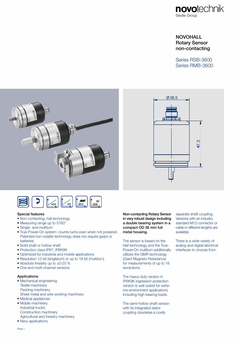
NOVOHALLRotary Sensor non-contacting
Series RSB-3600Series RMB-3600
Non-contacting Rotary Sensorin very robust design including a double bearing system in acompact OD 36 mm full metal housing.
The sensor is based on the Hall technology and the True- Power-On multiturn additionally utilizes the GMR technology (Giant Magneto Resistance)for measurements of up to 16 revolutions.
The heavy-duty version in IP6K9K ingression protection version is well suited for extre-me environment applications including high bearing loads.
The semi-hollow shaft version with its integrated stator coupling obsoletes a costly
separate shaft coupling.Versions with an industry standard M12-connector or cable in different lengths are available.
There is a wide variety of analog and digital electrical interfaces to choose from.
Dimension drawing 3
Mechanical data 4
5
Singleturn RSB-3600 6
Output Characteristics
Technical data analog versions 7
Ordering specifications analog versions 8
Technical data digital versions 9
Ordering specifications digital versions 10
Multiturn RSM-3600
Output Characteristics
Technical data analog versions 11
Ordering specifications analog versions 13
Technical data digital versions 14
Ordering specifications digital versions 15
Accessories
Shaft couplings 16
M12 connector system 17
Signal processing 18
Contents
Page 2 Back to contents
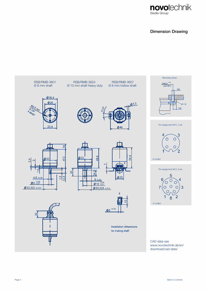
Dimension Drawing
Page 3 Back to contents
Pin assignment M12, 8 pin
Pin assignment M12, 4 pin
A-coded
A-coded
CAD data see www.novotechnik.de/en/download/cad-data/
RSB/RMB-3601 RSB/RMB-3624 RSB/RMB-3607 Ø 6 mm shaft Ø 10 mm shaft heavy duty Ø 6 mm hollow shaft
Mounting clamp
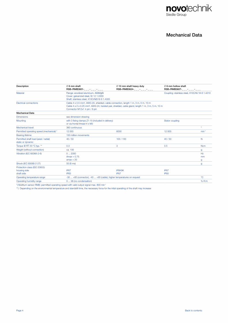
Mechanical Data
Dimensions see dimension drawing
Mounting with 3 fixing clamps Z1-15 (included in delivery)or via frontal thread 4 x M3
Stator coupling
Mechanical travel 360 continuous °
Permitted operating speed (mechanical) * 12 000 6000 12 000 min-1
Bearing lifetime 100 million movements
Permitted shaft load (axial / radial)static or dynamic
40 / 50 100 / 100 40 / 50 N
Torque @ RT 20 °C typ. ** 0.3 3 0.5 Ncm
Weight (without connection) ca. 100 g
Vibration (IEC 60068-2-6) 5 ... 2000Amax = 0.75amax = 20
Hzmmg
Shock (IEC 60068-2-27) 50 (6 ms) g
Protection class (ISO 20653)housing sideshaft side
IP67IP65
IP6K9KIP67
IP67IP65
Operating temperature range -30 ... +85 (connector), -40 ... +85 (cable), higher temperatures on request °C
Operating humidity range 0 ... 98 (no condensation) % R.H.
*) Multiturn sensor RMB: permitted operating speed with valid output signal max. 800 min-1
**) Depending on the environmental temperature and standstill time, the necessary force for the inital operating of the shaft may increase
Mechanical Data
Page 4 Back to contents
Description Ø 6 mm shaftRSB-/RMB3601-_ _ _ - _ _ _ - _ _ _
Ø 10 mm shaft heavy dutyRSB-/RMB3624-_ _ _ - _ _ _ - _ _ _
Ø 6 mm hollow shaftRSB-/RMB3607-_ _ _ - _ _ _ - _ _ _
Material Flange: anodized aluminum, AlSiMgBiCover: galvanized steel, St 12 1.0330Shaft: stainless steel, X10CrNiS18-9 1.4305
Coupling: stainless steel, X10CrNi 18-8 1.4310
Electrical connections Cable 4 x 0.5 mm², AWG 20, shielded, cable connection, length 1 m, 3 m, 5 m, 10 mCable 4 x 2 x 0.25 mm², AWG 24, twisted pair, shielded, cable gland, length 1 m, 3 m, 5 m, 10 mConnector M12x1 4 pin / 8 pin
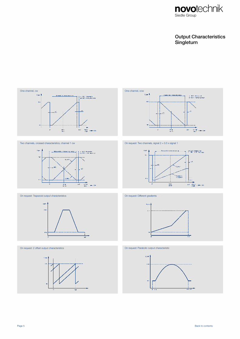
Output CharacteristicsSingleturn
Page 5 Back to contents
One-channel, cw One-channel, ccw
Two channels, crossed characteristics, channel 1 cw On request: Two channels, signal 2 = 0.5 x signal 1
On request: Different gradients
On request: 2 offset output characteristics On request: Parabolic output characteristic
On request: Trapezoid output characteristics
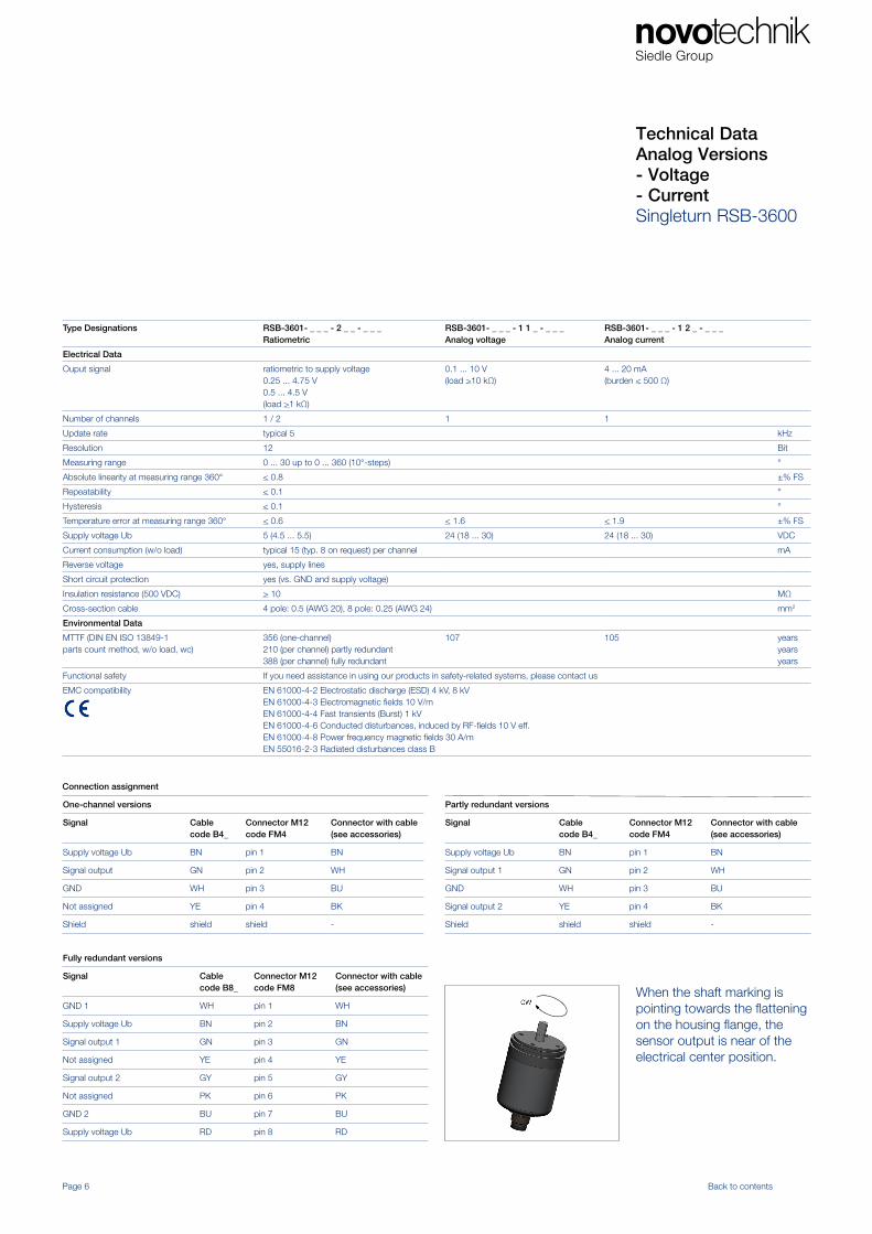
Technical Data Analog Versions - Voltage- CurrentSingleturn RSB-3600
Type Designations RSB-3601- _ _ _ - 2 _ _ - _ _ _Ratiometric
RSB-3601- _ _ _ - 1 1 _ - _ _ _ Analog voltage
RSB-3601- _ _ _ - 1 2 _ - _ _ _Analog current
Electrical Data
Ouput signal ratiometric to supply voltage 0.25 ... 4.75 V0.5 ... 4.5 V(load >1 kΩ)
0.1 ... 10 V (load >10 kΩ)
4 ... 20 mA(burden < 500 Ω)
Number of channels 1 / 2 1 1
Update rate typical 5 kHz
Resolution 12 Bit
Measuring range 0 ... 30 up to 0 ... 360 (10°-steps) °
Absolute linearity at measuring range 360° < 0.8 ±% FS
Repeatability < 0.1 °
Hysteresis < 0.1 °
Temperature error at measuring range 360° < 0.6 < 1.6 < 1.9 ±% FS
Supply voltage Ub 5 (4.5 ... 5.5) 24 (18 ... 30) 24 (18 ... 30) VDC
Current consumption (w/o load) typical 15 (typ. 8 on request) per channel mA
Reverse voltage yes, supply lines
Short circuit protection yes (vs. GND and supply voltage)
Insulation resistance (500 VDC) > 10 MΩ
Cross-section cable 4 pole: 0.5 (AWG 20), 8 pole: 0.25 (AWG 24) mm2
Environmental Data
MTTF (DIN EN ISO 13849-1parts count method, w/o load, wc)
356 (one-channel) 210 (per channel) partly redundant388 (per channel) fully redundant
107 105 yearsyearsyears
Functional safety If you need assistance in using our products in safety-related systems, please contact us
EMC compatibility EN 61000-4-2 Electrostatic discharge (ESD) 4 kV, 8 kVEN 61000-4-3 Electromagnetic fields 10 V/mEN 61000-4-4 Fast transients (Burst) 1 kVEN 61000-4-6 Conducted disturbances, induced by RF-fields 10 V eff.EN 61000-4-8 Power frequency magnetic fields 30 A/mEN 55016-2-3 Radiated disturbances class B
Connection assignment
One-channel versions
Signal Cable code B4_
Connector M12code FM4
Connector with cable (see accessories)
Supply voltage Ub BN pin 1 BN
Signal output GN pin 2 WH
GND WH pin 3 BU
Not assigned YE pin 4 BK
Shield shield shield -
Partly redundant versions
Signal Cable code B4_
Connector M12code FM4
Connector with cable(see accessories)
Supply voltage Ub BN pin 1 BN
Signal output 1 GN pin 2 WH
GND WH pin 3 BU
Signal output 2 YE pin 4 BK
Shield shield shield -
Page 6 Back to contents
Fully redundant versions
Signal Cable code B8_
Connector M12code FM8
Connector with cable(see accessories)
GND 1 WH pin 1 WH
Supply voltage Ub BN pin 2 BN
Signal output 1 GN pin 3 GN
Not assigned YE pin 4 YE
Signal output 2 GY pin 5 GY
Not assigned PK pin 6 PK
GND 2 BU pin 7 BU
Supply voltage Ub RD pin 8 RD
When the shaft marking is pointing towards the flattening on the housing flange, the sensor output is near of the electrical center position.
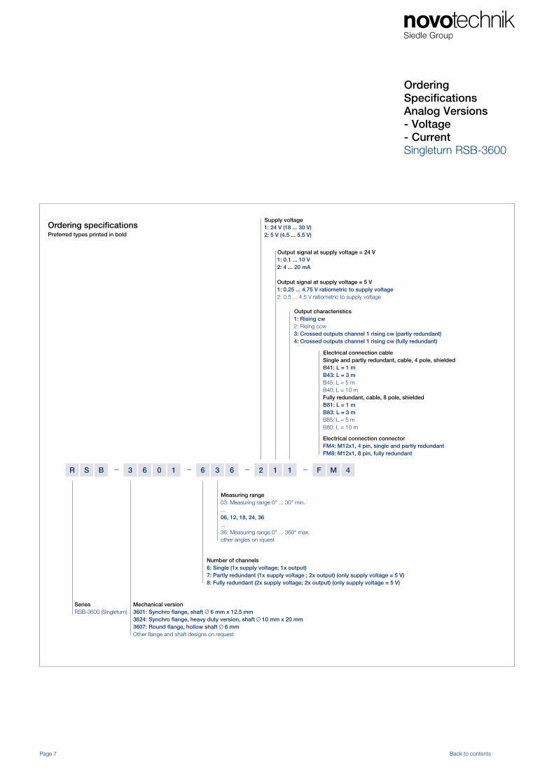
Ordering SpecificationsAnalog Versions- Voltage- CurrentSingleturn RSB-3600
– ––R 126361063BS 1
Supply voltage1: 24 V (18 ... 30 V)2: 5 V (4.5 ... 5.5 V)
Electrical connection cable Single and partly redundant, cable, 4 pole, shieldedB41: L = 1 mB43: L = 3 mB45: L = 5 mB40: L = 10 mFully redundant, cable, 8 pole, shieldedB81: L = 1 mB83: L = 3 mB85: L = 5 mB80: L = 10 m
Electrical connection connectorFM4: M12x1, 4 pin, single and partly redundantFM8: M12x1, 8 pin, fully redundant
Output characteristics1: Rising cw 2: Rising ccw 3: Crossed outputs channel 1 rising cw (partly redundant)4: Crossed outputs channel 1 rising cw (fully redundant)
Measuring range03: Measuring range 0° ... 30° min....06, 12, 18, 24, 36...36: Measuring range 0° ... 360° max.other angles on rquest
Output signal at supply voltage = 24 V1: 0.1 ... 10 V 2: 4 ... 20 mA
Output signal at supply voltage = 5 V1: 0.25 ... 4.75 V ratiometric to supply voltage2: 0.5 ... 4.5 V ratiometric to supply voltage
Number of channels6: Single (1x supply voltage; 1x output) 7: Partly redundant (1x supply voltage ; 2x output) (only supply voltage = 5 V) 8: Fully redundant (2x supply voltage; 2x output) (only supply voltage = 5 V)
SeriesRSB-3600 (Singleturn)
Mechanical version3601: Synchro flange, shaft Ø 6 mm x 12.5 mm3624: Synchro flange, heavy duty version, shaft Ø 10 mm x 20 mm3607: Round flange, hollow shaft Ø 6 mmOther flange and shaft designs on request
– MF 4
Ordering specifications Preferred types printed in bold
Page 7 Back to contents
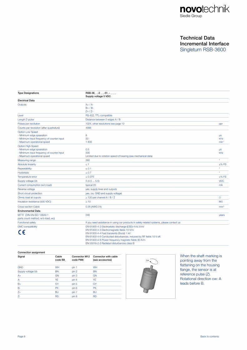
Type Designations RSB-36_ _-2 _ _-51_- _ _ _Supply voltage 5 VDC
Electrical Data
Outputs A+ / A-B+ / B-Z+ / Z-
Level RS-422, TTL-compatible
Length Z-pulse Distance between 2 edges A / B
Pulses per revolution 1024, other resolutions see page 12 ppr
Counts per revolution (after quadrature) 4096
Option Low Speed- Minimum edge spearation- Minimum input frequency of counter input- Maximum operational speed
8321 800
µskHzmin-1
Option High Speed- Minimum edge spearation- Minimum input frequency of counter input- Maximum operational speed
0.5500 Limited due to rotation speed of bearing (see mechanical data)
µskHz
Measuring range 360 °
Absolute linearity < 1 ±% FS
Repeatability < 0.1 °
Hysteresis < 0.7 °
Temperature error < 0.375 ±% FS
Supply voltage Ub 5 (4.5 ... 5.5) VDC
Current consumption (w/o load) typical 20 mA
Reverse voltage yes, supply lines and outputs
Short circuit protection yes, (vs. GND and supply voltage)
Ohmic load at ouputs > 120 per channel A / B / Z Ω
Insulation resistance (500 VDC) > 10 MΩ
Cross-section Cable 0.25 (AWG 24) mm2
Environmental Data
MTTF (DIN EN ISO 13849-1parts count method, w/o load, wc)
246 years
Functional safety If you need assistance in using our products in safety-related systems, please contact us
EMC compatibility EN 61000-4-2 Electrostatic discharge (ESD) 4 kV, 8 kVEN 61000-4-3 Electromagnetic fields 10 V/mEN 61000-4-4 Fast transients (Burst) 1 kVEN 61000-4-6 Conducted disturbances, induced by RF fields 10 V eff.EN 61000-4-8 Power frequency magnetic fields 30 A/mEN 55016-2-3 Radiated disturbances class B
Technical DataIncremental InterfaceSingleturn RSB-3600
Connection assignment
Signal Cablecode B8_
Connector M12code FM8
Connector with cable(see accesories)
GND WH pin 1 WH
Supply voltage Ub BN pin 2 BN
A+ GN pin 3 GN
A- YE pin 4 YE
B+ GY pin 5 GY
B- PK pin 6 PK
Z+ BU pin 7 BU
Z- RD pin 8 RD
Page 8 Back to contents
When the shaft marking is pointing away from the flattening on the housing flange, the sensor is at reference pulse (Z).Rotational direction cw: A leads before B.

Technical DataIncremental InterfaceSingleturn RSB-3600
Incremental protocol
Page 9 Back to contents
Electrical Data
Pulses per revolution 1024 512 256 128 ppr
Counts per revolution (after quadrature) 4096 2048 1024 512
Option Low Speed- Minimal edge separation- Minimum input frequency of counter input- Maximum operational speed
8321800
323600
32*7200**
32*14400**
µskHzmin-1
Option High Speed- Minimal edge separation- Minimum input frequency of counter input- Maximum operational speed
0.5500 500 500* 105* see note **
µskHz
*) The requirement for the minimum input frequency of counter input is reduced at lower speed (see charts below)**) Maximum operating speed is limited by maximum rotation speed of bearing (see Mechanical Data)
Page 10 Back to contents
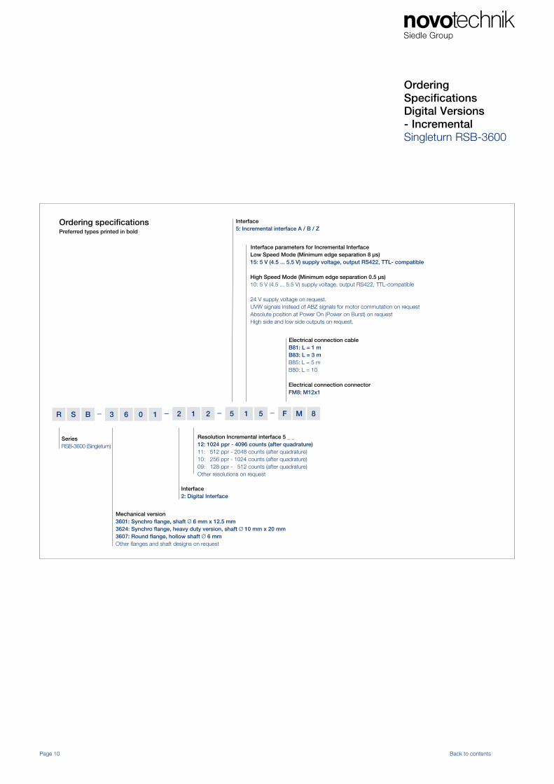
Ordering SpecificationsDigital Versions- IncrementalSingleturn RSB-3600
– ––R 152121063BS 5
Interface5: Incremental interface A / B / Z
Interface parameters for Incremental InterfaceLow Speed Mode (Minimum edge separation 8 µs) 15: 5 V (4.5 ... 5.5 V) supply voltage, output RS422, TTL- compatible
High Speed Mode (Minimum edge separation 0.5 µs) 10: 5 V (4.5 ... 5.5 V) supply voltage, output RS422, TTL-compatible 24 V supply voltage on request.UVW signals instead of ABZ signals for motor commutation on requestAbsolute position at Power On (Power on Burst) on request High side and low side outputs on request.
Interface2: Digital Interface
SeriesRSB-3600 (Singleturn)
Mechanical version3601: Synchro flange, shaft Ø 6 mm x 12.5 mm3624: Synchro flange, heavy duty version, shaft Ø 10 mm x 20 mm3607: Round flange, hollow shaft Ø 6 mmOther flanges and shaft designs on request
– MF 8
Ordering specificationsPreferred types printed in bold
Electrical connection cableB81: L = 1 mB83: L = 3 m B85: L = 5 mB80: L = 10
Electrical connection connectorFM8: M12x1
Resolution Incremental interface 5 _ _12: 1024 ppr - 4096 counts (after quadrature)11: 512 ppr - 2048 counts (after quadrature)10: 256 ppr - 1024 counts (after quadrature) 09: 128 ppr - 512 counts (after quadrature) Other resolutions on request

Output CharacteristicsMultiturn
Page 11 Back to contents
Output signals measuring range 15 ... 16 turns
Output signals measuring range 2 ... 14 turns
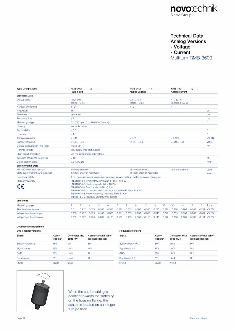
Technical Data Analog Versions - Voltage- Current Multiturn RMB-3600
Type Designations RMB-3601- _ _ _ -2 _ _ - _ _ _Ratiometric
RMB-3601- _ _ _ -11_ - _ _ _Analog voltage
RMB-3601- _ _ _ -12 _ - _ _ _Analog current
Electrical Data
Output signal ratiometric (load > 10 kΩ)
0.1 ... 10 V(load > 10 kΩ)
4 ... 20 mA(burden < 500 Ω)
Number of channels 1 / 2 1 / 2 1
Resolution 16 bit
Start time typical 10 ms
Response time < 2 ms
Measuring range 0 ... 720 up to 0 ... 5760 (360°-steps) °
Linearity see table below
Repeatability < 0.5 °
Hysteresis < 1 °
Temperature error < 0.15 < 0.31 < 0.625 ±% FS
Supply voltage Ub 5 (4.5 ... 5.5) 24 (18 ... 30) 24 (18 ... 30) VDC
Current consumption (w/o load) typical 30 mA
Reverse voltage yes, supply lines and outputs
Short circuit protection yes (vs. GND and supply voltage)
Insulation resistance (500 VDC) > 10 MΩ
Cross-section cable 0.5 (AWG 20) mm2
Environmental Data
MTTF (DIN EN ISO 13849-1parts count method. w/o load. wc)
175 one-channel175 (per channel) redundant
184 one-channel184 (per channel) redundant
186 one-channel years
years
Functional safety If you need assistance in using our products in safety-related systems, please contact us
EMC compatibility EN 61000-4-2 Electrostatic discharge (ESD) 4 kV, 8 kVEN 61000-4-3 Electromagnetic fields 10 V/mEN 61000-4-4 Fast transients (Burst) 1 kVEN 61000-4-6 Conducted disturbances, induced by RF fields 10 V eff.EN 61000-4-8 Power frequency magnetic fields 30 A/mEN 55016-2-3 Radiated disturbances class B
Linearities
Measuring range 2 3 4 5 6 7 8 9 10 11 12 13 14 15 16 Turns
Absolute linearity max. 0.5 0.417 0.375 0.350 0.333 0.321 0.313 0.306 0.300 0.295 0.292 0.288 0.286 0.283 0.281 ±% FS
Independent linearity typ. 0.250 0.167 0.125 0.100 0.083 0.071 0.063 0.056 0.050 0.045 0.042 0.039 0.036 0.033 0.031 ±% FS
Independent linearity max. 0.350 0.267 0.225 0.200 0.183 0.171 0.163 0.156 0.150 0.145 0.142 0.138 0.136 0.133 0.131 ±% FS
Page 12 Back to contents
Copnnection assignment
One-channel versions
Signal Cable code B4_
Connector M12code FM4
Connector with cable(see accessories)
Supply voltage Ub BN pin 1 BN
Signal output GN pin 2 WH
GND WH pin 3 BU
Not assigned YE pin 4 BK
Shield shield shield -
Redundant versions
Signal Cablecode B4_
Connector M12code FM4
Connector with cable(see accessories)
Supply voltage Ub BN pin 1 BN
Signal output 1 GN pin 2 WH
GND WH pin 3 BU
Signal output 2 YE pin 4 BK
Shield shield shield -
When the shaft marking is pointing towards the flattening on the housing flange, the sensor is located on an integer turn position.

– ––R 120101063BM 1
Supply voltage1: 24 V (18 ... 30 V)2: 5 V (4.5 ... 5.5 V)
Electrical connection cable B41: L = 1 mB43: L = 3 mB45: L = 5 mB40: L = 10 m
Electrical connection connectorFM4: M12x1
Output characteristics1: Rising cw 2: Rising ccw 3: Crossed outputs channel 1 rising cw (redundant)Other output characteristics on request
Output signal at supply voltage = 5 V1: 0.25 ... 4.75 V ratiometric 2: 0.5 ... 4.5 V ratiometric
Output signal at supply voltage = 24 V1: 0.1 ... 10 V2: 4... 20 mA (only one-channel)
Number of turns for output characteristicFrom 002 = 2 turns up to 016 = 16 turns, increment 1 turn003, 006, 010, 016Other measuring ranges on request
SeriesRMB-3600 (Multiturn)
Mechanical version3601: Synchro flange, shaft Ø 6 mm x 12.5 mm3624: Synchro flange, heavy duty version, shaft Ø 10 mm x 20 mm3607: Round flange, hollow shaft Ø 6 mmOther flange and shaft designs on request
– MF 4
Ordering specifications Preferred types printed in bold
Ordering SpecificationsAnalog Versions - Voltage- CurrentMultiturn RMB-3600
Page 13 Back to contents

Page 14 Back to contents
Type designations RMB-36_ _-2_ _-44 _- _ _ _Supply voltage 24 VDC
Electrical Data
Protocol SSI
Inputs RS422-compatible, CLK-lines via optocoupler galvanically isolated
Monoflop time (tm) 20 ±1 µs
Coding Gray, binary
Update rate (internal) 1 kHz
Resolution 16 or 18 across the entire measuring range Bit
Measuring range see ordering specifications
Absolute linearity 14 turns: < 0.03616 turns: < 0.031
±% FS±% FS
Repeatability < 0.5 °
Hysteresis < 1 °
Temperature error < 0.1 ±% FS
Supply voltage Ub 24 (10 ... 32), (5 V on request) VDC
Current consumption (w/o load) typical 10 mA
Reverse voltage yes, supply lines and outputs
Short circuit protection yes (vs. GND, max. 1 min)
Ohmic load at ouputs > 120 Ω
Maximum clock rate 1 MHz
Insulation resistance (500 VDC) > 10 MΩ
Cross-section cable 0.25 (AWG 24) mm2
Environmental Data
MTTF (DIN EN ISO 13849-1parts count method, w/o load, wc)
173 Years
Functional safety If you need assistance in using our products in safety-related systems, please contact us
EMC compatibility EN 61000-4-2 Electrostatic discharge (ESD) 4 kV, 8 kVEN 61000-4-3 Electromagnetic fields 10 V/mEN 61000-4-4 Fast transients (Burst) 1 kVEN 61000-4-6 Conducted disturbances, induced by RF fields 10 V eff.EN 61000-4-8 Power frequency magnetic fields 30 A/mEN 55016-2-3 Radiated disturbances class B
Technical DataDigital Versions- SSIMultiturn RMB-3600
Connection assignment
Signal Cable code B8_
Connector M12code FM8
Connector with cable (see accessories)
GND WH pin 1 WH
Supply voltage Ub BN pin 2 BN
CLK + GN pin 3 GN
CLK - YE pin 4 YE
Data + GY pin 5 GY
Data - PK pin 6 PK
Do not connect BU pin 7 BU
Do not connect RD pin 8 RD
When the shaft marking is pointing towards the flattening on the housing flange, the sensor is located on an integer turn position.

Page 15 Back to contents
Ordering SpecificationsDigital VersionsMultiturn RMB-3600
– ––R 444121063BM 1
Interface4: Synchronous Serial Interface (SSI)
Interface parameters SSI Interface41: SSI 16 bit, Gray code, rising cw43: SSI 25 bit (18 bit data), Gray code, rising cw45: SSI 16 bit, binary code, rising cw47: SSI 25 bit (18 bit data), binary code, rising cw
SeriesRMB-3600 (Multiturn)
Mechanical version3601: Synchro flange, shaft Ø 6 mm x 12.5 mm3624: Synchro flange, heavy duty version, shaft Ø 10 mm x 20 mm3607: Round flange, hollow shaft Ø 6 mmOther flanges and shaft designs on request
– MF 8
Ordering specificationsPreferred types printed in bold
Electrical connection cableB81: L = 1 mB83: L = 3 mB85: L = 5 mB80: L = 10 m
Electrical connection connectorFM8: M12x1
Number of turns for output characteristic14: 14 turns = 5040°, measuring range controlled16: 16 turns = 5760°, measruing range not controlled
Interface2: Digital interface
Page 16 Back to contents
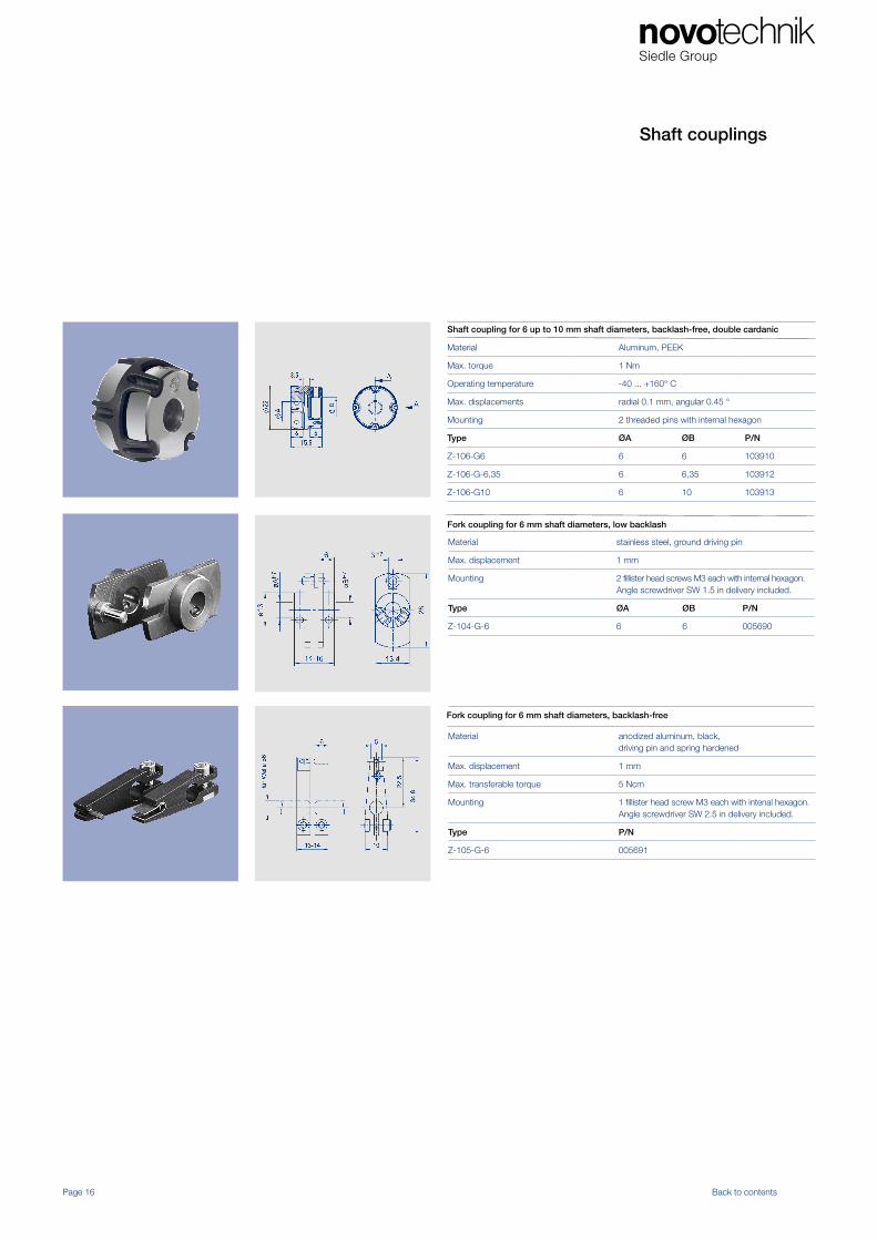
Shaft couplings
Shaft coupling for 6 up to 10 mm shaft diameters, backlash-free, double cardanic
Material Aluminum, PEEK
Max. torque 1 Nm
Operating temperature -40 ... +160° C
Max. displacements radial 0.1 mm, angular 0.45 °
Mounting 2 threaded pins with internal hexagon
Type ØA ØB P/N
Z-106-G6 6 6 103910
Z-106-G-6,35 6 6,35 103912
Z-106-G10 6 10 103913
Fork coupling for 6 mm shaft diameters, low backlash
Material stainless steel, ground driving pin
Max. displacement 1 mm
Mounting 2 fillister head screws M3 each with internal hexagon.Angle screwdriver SW 1.5 in delivery included.
Type ØA ØB P/N
Z-104-G-6 6 6 005690
Fork coupling for 6 mm shaft diameters, backlash-free
Material anodized aluminum, black, driving pin and spring hardened
Max. displacement 1 mm
Max. transferable torque 5 Ncm
Mounting 1 fillister head screw M3 each with intenal hexagon. Angle screwdriver SW 2.5 in delivery included.
Type P/N
Z-105-G-6 005691
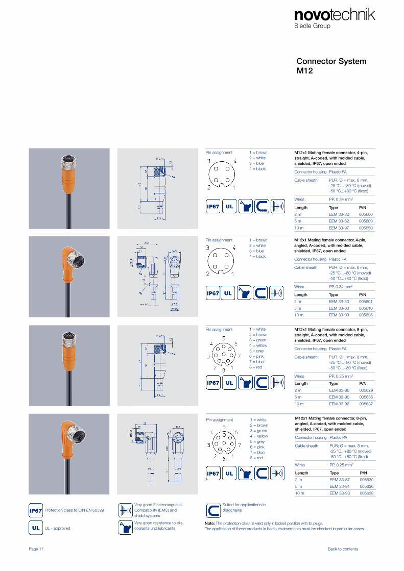
Connector System M12
Page 17 Back to contents
M12x1 Mating female connector, 4-pin, straight, A-coded, with molded cable, shielded, IP67, open ended
Connector housing Plastic PA
Cable sheath PUR; Ø = max. 6 mm,-25 °C...+80 °C (moved)-50 °C...+80 °C (fixed)
Wires PP, 0.34 mm2
1 = brown 2 = white3 = blue 4 = black
Pin assignment
Length Type P/N
2 m EEM 33-32 005600
5 m EEM 33-62 005609
10 m EEM 33-97 005650
Pin assignment M12x1 Mating female connector, 4-pin, angled, A-coded, with molded cable, shielded, IP67, open ended
Connector housing Plastic PA
Cable sheath PUR; Ø = max. 6 mm,-25 °C...+80 °C (moved)-50 °C...+80 °C (fixed)
Wires PP, 0.34 mm2
1 = brown 2 = white3 = blue 4 = black
Length Type P/N
2 m EEM 33-33 005601
5 m EEM 33-63 005610
10 m EEM 33-99 005696
Pin assignment M12x1 Mating female connector, 8-pin, straight, A-coded, with molded cable, shielded, IP67, open ended
Connector housing Plastic PA
Cable sheath PUR; Ø = max. 8 mm,-25 °C...+80 °C (moved)-50 °C...+80 °C (fixed)
Wires PP, 0.25 mm2
1 = white 2 = brown3 = green4 = yellow5 = grey6 = pink7 = blue 8 = red
Length Type P/N
2 m EEM 33-86 005629
5 m EEM 33-90 005635
10 m EEM 33-92 005637
Pin assignment M12x1 Mating female connector, 8-pin, angled, A-coded, with molded cable, shielded, IP67, open ended
Connector housing Plastic PA
Cable sheath PUR; Ø = max. 8 mm,-25 °C...+80 °C (moved)-50 °C...+80 °C (fixed)
Wires PP, 0.25 mm2
1 = white 2 = brown3 = green4 = yellow5 = grey6 = pink7 = blue 8 = red
Length Type P/N
2 m EEM 33-87 005630
5 m EEM 33-91 005636
10 m EEM 33-93 005638
Note: The protection class is valid only in locked position with its plugs.The application of these products in harsh environments must be checked in particular cases.
Protection class to DIN EN 60529
UL - approved
Very good Electromagnetic Compatibility (EMC) and shield systems
Very good resistance to oils, coolants und lubricants
Suited for applications in dragchains
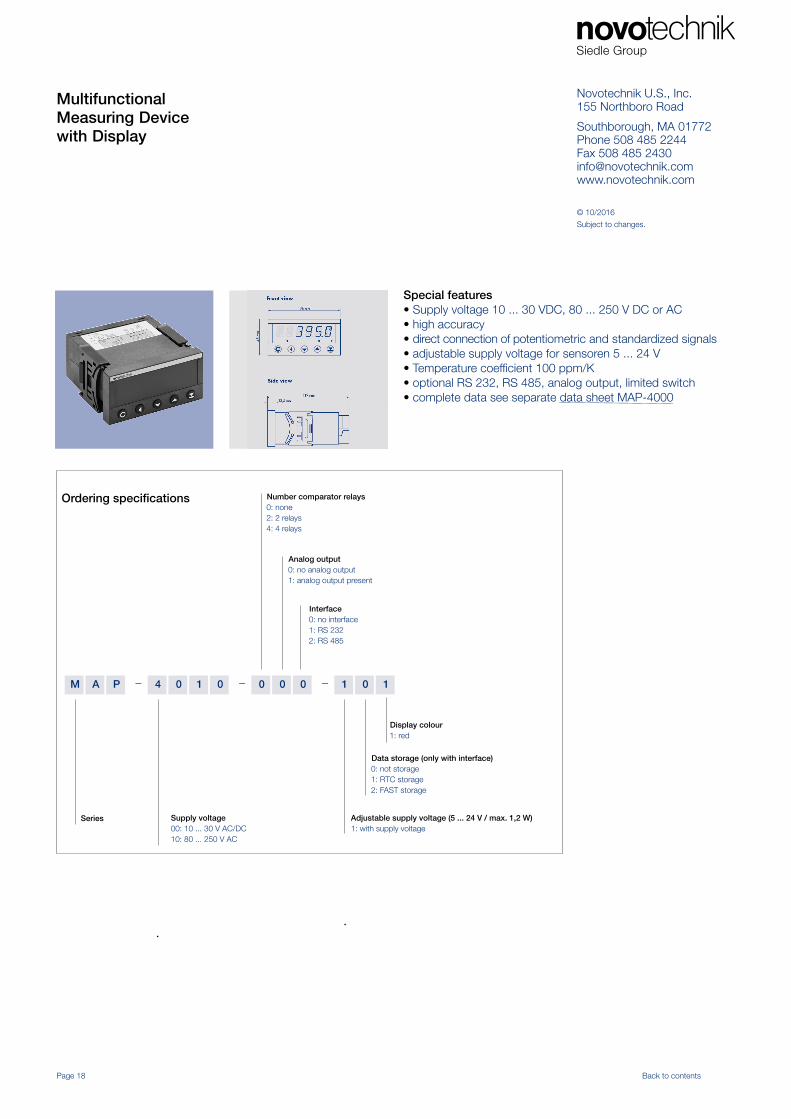
MultifunctionalMeasuring Devicewith Display
Page 18 Back to contents
– ––M 010000104PA 1
Number comparator relays0: none2: 2 relays 4: 4 relays
Display colour1: red
Data storage (only with interface)0: not storage1: RTC storage2: FAST storage
Analog output0: no analog output1: analog output present
Series Supply voltage00: 10 ... 30 V AC/DC10: 80 ... 250 V AC
Adjustable supply voltage (5 ... 24 V / max. 1,2 W)1: with supply voltage
Ordering specifications
Interface0: no interface1: RS 2322: RS 485
Special features• Supply voltage 10 ... 30 VDC, 80 ... 250 V DC or AC• high accuracy• direct connection of potentiometric and standardized signals• adjustable supply voltage for sensoren 5 ... 24 V• Temperature coefficient 100 ppm/K• optional RS 232, RS 485, analog output, limited switch• complete data see separate data sheet MAP-4000
© 10/2016
Subject to changes.
Novotechnik U.S., Inc.155 Northboro Road
Southborough, MA 01772Phone 508 485 2244Fax 508 485 [email protected]