novosibirsk terahertz free electron laser terahertz radiation and for the study of interaction of...
TRANSCRIPT
This content has been downloaded from IOPscience. Please scroll down to see the full text.
Download details:
IP Address: 129.57.74.207
This content was downloaded on 29/03/2015 at 20:19
Please note that terms and conditions apply.
Novosibirsk terahertz free electron laser: instrumentation development and experimental
achievements
View the table of contents for this issue, or go to the journal homepage for more
2010 Meas. Sci. Technol. 21 054017
(http://iopscience.iop.org/0957-0233/21/5/054017)
Home Search Collections Journals About Contact us My IOPscience
IOP PUBLISHING MEASUREMENT SCIENCE AND TECHNOLOGY
Meas. Sci. Technol. 21 (2010) 054017 (13pp) doi:10.1088/0957-0233/21/5/054017
Novosibirsk terahertz free electron laser:instrumentation development andexperimental achievementsB A Knyazev1,2, G N Kulipanov1 and N A Vinokurov1
1 Budker Institute of Nuclear Physics SB RAS, 11 Lavrentyeva Ave, Novosibirsk 630090, Russia2 Novosibirsk State University, 2 Pirogova Str., Novosibirsk 630090, Russia
E-mail: [email protected]
Received 6 November 2009, in final form 4 January 2010Published 23 March 2010Online at stacks.iop.org/MST/21/054017
AbstractNowadays, the Novosibirsk free electron laser (NovoFEL) is the most intense radiation sourcein the terahertz spectral range. It operates in the continuous mode with a pulse repetition rateof up to 11.2 MHz (5.6 MHz in the standard mode) and an average power of up to 500 W. Theradiation wavelength can be precisely tuned from 120 to 240 mm with a relative line width of0.3–1%, which corresponds to the Fourier transform limit for a micropulse length of 40–100ps. The laser radiation is plane-polarized and completely spatially coherent. The radiation istransmitted to six user stations through a nitrogen-filled beamline. Characteristics of theNovoFEL radiation differ drastically from those of conventional low-power (and oftenbroadband) terahertz sources, which enables obtaining results impossible with other sources,but necessitates the development of special experimental equipment and techniques. In thispaper, we give a review of the instrumentation developed for control and detection ofhigh-power terahertz radiation and for the study of interaction of the radiation with matter.Quasi-optic elements and systems, one-channel detectors, power meters, real-time imagers,spectroscopy devices and other equipment are described. Selected experimental results(continuous optical discharge, material and biology substance ablation, real-time imagingattenuated total reflection spectroscopy, speckle metrology, polarization rotation by an artificialchiral structure, terahertz radioscopy and imaging) are also presented in the paper. In the nearfuture, after commissioning another four electron racetracks and two optical resonators,intense radiation in the range from 5 to 240 μm will be available for user experiments.
Keywords: free electron laser, terahertz radiation, terahertz optics, terahertz spectroscopy,ablation, optical discharge, radioscopy
(Some figures in this article are in colour only in the electronic version)
1. Introduction
The exponentially growing number of publications devotedto the development of terahertz sources and applications ofterahertz radiation reflects the expectation of a breakthroughto new technologies involving this frequency band. Theinterest in the terahertz radiation is due to its followingproperties: it is a non-ionizing radiation (the photon energyranges from 0.04 eV to 0.004 eV); the radiation passes throughopaque media and weakly dispersive materials relatively well
owing to strong suppression of Rayleigh scattering (1/λ4); thefrequency range of the radiation covers the region of rotationalspectra of molecules, vibrations of biologically importantcollective modes of DNA and proteins and frequenciescharacteristic of intermolecular interactions; the terahertzradiation corresponds to the energy region of hydrogen bondsand van der Waals forces of intermolecular interactions.
The invention of broadband terahertz generators, whichare based on femtosecond lasers, triggered research interahertz imaging and tomography, spectroscopy, nonlinear
0957-0233/10/054017+13$30.00 1 © 2010 IOP Publishing Ltd Printed in the UK & the USA

Meas. Sci. Technol. 21 (2010) 054017 B A Knyazev et al
(a )
(b)
Figure 1. (a) Schematic of the terahertz free electron laser; (b) the full-scale Novosibirsk free electron laser. The terahertz FEL is inoperation, the far-infrared FEL has recently been commissioned, the short-wave FEL is under assembly.
optics, biology and medicine, materials science, securityand other applications. In applications which require tunablemonochromatic coherent radiation, backward wave oscillators(in the millimeter and high submillimeter regions), injection-seeding parametric generators and difference-frequencygenerators are commonly used. However, the average powerof all the above-mentioned generators is very low. Theabove-mentioned techniques and methods are described in acomprehensive review [1].
More intense terahertz radiation can be emitted usingsources based on the radiation of relativistic electrons inmagnetic structures such as synchrotrons and free electronlasers (FEL) [2]. The average radiation power of conventionalterahertz free electron lasers at the laboratories of Stanford [3],UCSB [4], FOM-Institute [5], Osaka [6], INEA [7] and KAERI[8] is close to 1 W. Because of the relatively low FEL efficiency,any further increase in the output power can only be achievedusing energy-recovery systems. The capabilities of such atechnique have been demonstrated on the near-infrared FEL(JFEL), which has recently been commissioned at JeffersonLaboratory [9] and is based on an energy recovery linac (ERL).Now it generates broadband radiation in the near- and mid-infrared spectral ranges with an average power as high as10 kW. The same facility is also used as a 100 W average-powerradiation source, which emits broadband terahertz radiationwhen a subpicosecond electron bunch passes bending magnets(coherent synchrotron radiation in the THz region).
In this paper we give a brief description of the ERL-basedterahertz Novosibirsk free electron laser (NovoFEL) and thesurvey of the instrumentation developed for experiments withlaser radiation. Examples of experimental results achieved atthe facility are also presented.
2. Novosibirsk terahertz free electron laser and userstations
Novosibirsk high-power free electron laser (NovoFEL) [10]differs from other ERL-based FELs [9, 11] in low-frequency(180 MHz) non-superconducting RF cavities and a longerwavelength operation range. The first stage of the Novosibirskfree electron laser, generating terahertz radiation, wascommissioned in 2003 [12]. It is (figure 1(a)) a FEL basedon a single-pass ERL with the following parameters: theelectron energy is 12 MeV; charge per bunch is 1.5 nC; thebunch repetition rate is 5.6, 11.2 or 22.5 MHz; the maximumaverage current is 30 mA and the bunch duration is 40–100 ps.Two identical 4 m electromagnetic planar undulators, having aperiod of 120 mm, a gap of 80 mm and an undulator parameterK of up to 1.2, are installed in the long straight section of theERL. The principle of free electron laser operation has beendescribed in many publications (e.g. in [13]).
The laser resonator [14] consists of two water-cooledspherical mirrors made of gold-plated copper. Their curvatureradius is 15 m and the distance between the mirrors is26.6 m. The front and rear mirrors have openings 3.5 mm and8 mm in diameter, respectively. The calculated transparencyof the mirror with the 8 mm hole at a wavelength of 150 μmis 1.5%. At this wavelength, the measured round-trip loss isnear 7%. The output radiation passes through two windows,which separate the ultrahigh vacuum system of the resonatorand accelerator from the atmosphere. Behind the front mirror,an additional iris and a normal-incidence quartz window areinstalled. Behind the rear one, there is a diamond window,tilted at the Brewster angle.
The laser generates tunable monochromatic radiationwithin the spectral range of 110–240 μm at the first harmonic,60–117 μm and 40–80 μm at the second and third harmonics,respectively. The maximum average power for the firstharmonic reaches 0.5 kW at a repetition rate of 11.2 MHz
2

Meas. Sci. Technol. 21 (2010) 054017 B A Knyazev et al
(a) (b)
(c)
Figure 2. (a) Brass Fresnel mirror and high-density polypropyleneFresnel lens; (b) mirror profile; (c) distribution of terahertz radiationin the mirror focal spot.
(routinely, the laser operates at a repetition rate of 5.6 MHz).The maximum average power of the second and thirdharmonics is 1.5% and 0.6% with respect to the first harmonic[15]. The micropulse length is about 100 ps, which providesa maximum peak power of about 1 MW. The relative spectralwidth is 0.25–1%, which is close to the Fourier transformlimit. The radiation is completely spatially coherent, andthe degree of linear polarization of radiation is better than99.6% [16].
The radiation of the terahertz FEL, emitted through themirror opening as a continuous train of pulses, is transmittedthrough an optical beamline (nitrogen-filled, 16 cm in innerdiameter) to the experimental halls. The ultrahigh vacuumsystem of the FEL and the gas-filled beamline are separatedby a diamond window 0.7 mm thick. Six user stations—themetrology station, the photochemistry station, the biologicalstation, the molecular spectroscopy station, the station forradioscopy and spectroscopy and the aerodynamics station—are now in operation (see figure 2 in [17]). The high averagepower (100–200 W) and large diameter (50–80 mm) of theterahertz beam at the user stations necessitate the developmentof adequate experimental equipment for radiation control anddetection, which is described below.
The full-scale Novosibirsk free electron laser facility isbased on the four-orbit 40 MeV electron energy recoverylinac. A schematic of the full-scale machine is shown in figure1(b). It is to generate radiation in the range from 5 μm to0.24 mm [18]. The orbit of the first stage with the terahertzFEL (see above) lies in the vertical plane. The four new turnsare being mounted in the horizontal plane. The bypass withthe far-infrared FEL has already been assembled in the secondstraight line section (about 20 MeV energy, figure 1(b)). Thebypass also provides about 0.7 m lengthening of the secondorbit. Therefore, when the bypass magnets are switched on,deceleration of the beam takes place at its third pass throughthe accelerating system. After that, the electrons come to thefirst orbit and, after the second deceleration, to the beam dump.
The second-orbit fixed-gap electromagnetic undulator isvery similar to the undulators of the first-orbit FEL, but
its gap is narrower. The optical resonator length is 20 m(12 wavelengths of the RF system). Therefore, the bunchrepetition rate for the initial operation is 7.5 MHz (the 24thsubharmonic of the RF system). The water-cooled mirrors aremade of copper and covered with gold. Outcoupling holes (3and 4 mm in diameter) also serve for alignment with a visiblereference laser. The first lasing of the FEL in the bypasswas achieved in the spring of 2009. At present, it spans thewavelength range from 40 to 80 μm. Optimization of thesecond laser system as well as the assembly of the third andfourth tracks is in progress.
The architecture and main capabilities of the control anddiagnostic system for the Novosibirsk FEL are described in[19]. The software developed for this system employs aclient–server model. The software is able to work in bothclient and server modes. It can also control various piecesof equipment: from the optical cavity mirrors of the FEL tothe local equipment of user stations. The mode of controlprogram operation and controlled equipment are determinedby external configuration files.
3. Instrumentation for THz beam controland transformation
Since the terahertz (submillimeter) spectral range lies betweenthe regions of ‘photonics’ and ‘electronics’, both quasi-opticand electronic techniques have been employed for control,transformation and detection of radiation. Experimentson diffraction using two-slit and bi-mirror Fresnel schemesshowed that NovoFEL radiation is completely spatiallycoherent, whereas the temporal coherence is limited by theradiation pulse length. Polarization characteristics of the laserbeam have been examined using a photolithographic polarizer[16]. It was shown that the radiation is practically completelyplane-polarized with a polarization degree not less than 99.6%.The last feature enabled using a different combination ofphotolithographic (from QMC Instruments Ltd and Tydex) andwire-mesh (from Lebedev Physical Institute) polarizers for thecontrol of both polarization direction and intensity attenuation.The polarizers operated properly at a power density of up to10 J cm−2.
Many materials are sufficiently transparent to the terahertzradiation, but the absorption coefficient of most of them is,however, substantially higher than that of optical materialsin the visible spectral range. In a number of experiments(see sections 5 and 6), we focused and imaged terahertzradiation with TPX lenses, whose transparency in both theterahertz and visible regions enabled easy alignment of opticalsystems. Employment of classical lenses in systems forwhich a high numerical aperture is critically important (seesections 6.1–6.2) is, however, limited by strong absorption(and, consequently, heating) at the center of a short-focus lens,which may lead to lens deformation and destruction. Usingreflective mirrors or diffractive optical elements (DOE) is asolution. A Fresnel mirror, for example, can be cooled easily incomparison with a parabolic mirror. An additional advantageof diffractive elements is the possibility of development of‘focusators’—diffractive optical elements intended for energy
3
Meas. Sci. Technol. 21 (2010) 054017 B A Knyazev et al
concentration into volumes of certain shapes. Such necessitycan arise, for example, in gas-dynamic experiments [20].
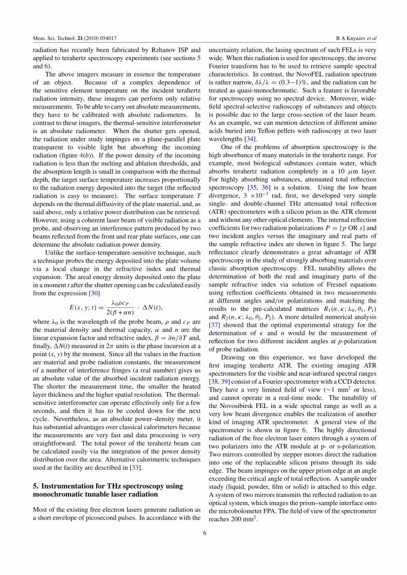
Two kinds of diffractive optical elements (figure 2) havebeen developed and tested using FEL radiation. Circular andelliptical brass mirrors with a parabolic profile of Fresnelzones [21, 22] were fabricated for λ = 130 μm using anumerical control machine (NCM). The machinery-turnedcircular Fresnel mirror exhibited perfect focusing with adiffraction efficiency of about 100%, whereas the diffractionefficiency of a simple reflective Fresnel zone plate, producedby etching of a copper clad fiberglass board, was less than 10%.The elliptical Fresnel mirror was drilled with another NCM.Though the surface roughness was 6–10 μm, the diffractionefficiency of the mirror was also close to 100%. A certainFresnel mirror has to be designed for a given wavelength. Achange in the wavelength leads to a change in the focal lengthand deterioration of focusing. The focal length of high-densitypolyethylene Fresnel lenses [23] is also proportional to thewavelength, but focusing remains perfect for any wavelength.A radiation resistance test for a Fresnel lens (1 mm thick,100 mm in diameter) has shown that it works properly in a100 W terahertz beam.
The large wavelength of terahertz radiation allows usingpolypropylene (PP) or Mylar (PTE) foils of a thickness muchless than the wavelength as effective beamsplitters for high-power beams [24]. High-density PP and PTE foils as well ashigh-resistance silicon plates are routinely used as windows orpath length compensators. The implementation of the quasi-optical elements is described below.
4. THz beam detection and imaging
In the section that follows we will be describing detectionmethods that encompass the detection of both promptand thermally induced radiation. Nowadays, highlysensitive photoconductive antennas and electro-optic crystals,which enable coherent detection of the wave electric field,or incoherent far-infrared interferometric systems usingcryogenic bolometers, are commonly used for detection oflow-intensity terahertz-waves [25]. Such systems are toosensitive to be used for detection of NovoFEL radiation.Single-channel pyroelectric (PE) detectors, linear PE arrayswith choppers and, if necessary, a phase lock-in amplifierand different kinds of uncooled bolometers are used for themeasurement of radiation intensity. The response time ofpyroelectric detectors is not less than 10 ms, whereas thatof most bolometers is close to 1 s. Since most of thesesystems have been developed and calibrated for employmentin the visible or infrared regions, they cannot be applied forthe measurement of the absolute value of terahertz radiationpower. Moreover, the effect of multiple-beam interferencein the input windows (and in the semitransparent sensitiveelements of some kind of bolometers) dramatically increasesin the terahertz region, which leads to considerable variationsin the detector sensitivity versus wavelength, incident angle,window wedging, radiation divergence, etc [24]. A techniquefor absolute power measurement will be described at the endof this section. Fast Schottky-diode detectors [26] were used
for recording the NovoFEL micropulse shape with a temporalresolution of 20–30 ps.
The high average power of the NovoFEL enables thedevelopment of imaging techniques different from thosecommonly used (e.g. [1]). Several techniques (figure 3), anear-infrared (NIR) thermal recorder [27], a microbolometerfocal plane array (FPA) [28], thermal-sensitive phosphorimage plates [29] as well as a thermal-sensitive visible lightinterferometer [30], have been applied to terahertz beamimaging. Since the photon energy of terahertz radiation istoo small to ionize or excite atomic or molecular transitionsdirectly, all these techniques are based on the thermal effect ofterahertz radiation. Here we will discuss the advantages anddrawbacks of these methods.
The thermal effect is routinely used for detection ofradiation in very different spectral regions. The mainadvantages of this method are its universality and simplicity.The implementation of this technique, however, is a matterof some difficulty. All imagers can be divided intodirect detectors, sensitive to terahertz radiation, such as themicrobolometer FPA and indirect detectors, which requireusing an intermediate ‘thermal screen’. Another classificationattribute is operation in the cw or transient time mode. Incw-mode techniques, temperature distribution gets to a steadystate after a short transient time.
In the case of a thermal-sensitive phosphor image plateor a thermal image plate (TIP), terahertz power densitydistribution can be retrieved via quenching the phosphor screenluminescence induced by UV radiation of a mercury lamp.We used a set of eight 3′′ × 3′′ phosphor screens developedby Macken Instruments Inc. [31] for imaging near- andmid-infrared radiation. Each screen consists of a thin filmwith a phosphor layer attached to a massive aluminum plate.The screens appeared to be rather transparent to terahertzradiation, and only the two most sensitive screens gave areasonable response on being exposed to an unfocused laserbeam. The magnitude of luminescence quenching versusradiation intensity at a wavelength of 130 μm for the mostsensitive thermal image plate #8, model 22-B, is given infigure 4(a). Phosphor luminescence was recorded with a720 × 576 pixel SONY DCR-TRV230E camcorder. Thespatial resolution of the thermal image plate is a convolutionof phosphor screen spatial resolution (PSSR), which is limitedby transverse thermal conductivity and modulation transferfunction of the recorder. The PSSR values for screens #8and #7 are 1.6 and 0.35 mm, respectively. Apparently, spatialresolution for less sensitive screens is close to the wavelengthlimit. Thus, a great advantage of thermal image plates is theircapability of large-field imaging, but their sensitivity is farfrom being perfect.
Another imager requiring a thermal screen is the liquidnitrogen-cooled NIR thermal recorder. In our first experimentswe used white or black paper as screens, but later, usingthermal image plates #5–#7, we obtained a better timeresolution. A small array size (128 × 128 elements) limitsthe applicability of the thermal recorder in terahertz imaging,but a high repetition rate (up to 50 Hz) enables employmentof the device in laser beam tracing.
4

Meas. Sci. Technol. 21 (2010) 054017 B A Knyazev et al
Figure 3. Imaging techniques used for the visualization of intense terahertz radiation.
(a) (b)
Figure 4. (a) Response of the temperature-sensitive phosphor screen (Macken Instruments Inc., thermal image plate #8) to the intensity ofincoming terahertz radiation: the red curve is a least-squares four-parameter fitting by the Mott–Seitz law for thermal quenching ofluminescence; (b) schematics of superficial heat with laser radiation of materials of different thermal diffusivities.
An uncooled 160 × 120 vanadium oxide microbolometerfocal plane array (FPA) with a germanium window andphysical dimensions of 8.2 × 6.1 mm2, initially developedby Rzhanov Institute of Semiconductor Physics for detectionof mid-IR radiation [32], was adapted to imaging of terahertzradiation [28]. Since the FPA is sensitive directly to terahertzradiation, it turned out to be one of the best terahertz imagers.
For λ = 130 μm, the effective FPA responsivity was S =1.6 ×10⁴ V W−1, the sensitivity threshold was 1.3 ×10⁻³ Wcm−2, the optical noise equivalent power was NEPO = 200pW Hz−1/2 and the signal-to-noise ratio was SNR = 4 ×10³,i.e. more than 70 dB. Real-time imaging was demonstrated at afrequency as high as 90 frames s−1. A novel 320 × 240 pixelmatrix with a silicon window more transparent to terahertz
5
Meas. Sci. Technol. 21 (2010) 054017 B A Knyazev et al
radiation has recently been fabricated by Rzhanov ISP andapplied to terahertz spectroscopy experiments (see sections 5and 6).
The above imagers measure in essence the temperatureof an object. Because of a complex dependence ofthe sensitive element temperature on the incident terahertzradiation intensity, these imagers can perform only relativemeasurements. To be able to carry out absolute measurements,they have to be calibrated with absolute radiometers. Incontrast to these imagers, the thermal-sensitive interferometeris an absolute radiometer. When the shutter gets opened,the radiation under study impinges on a plane-parallel platetransparent to visible light but absorbing the incomingradiation (figure 4(b)). If the power density of the incomingradiation is less than the melting and ablation thresholds, andthe absorption length is small in comparison with the thermaldepth, the target surface temperature increases proportionallyto the radiation energy deposited into the target (the reflectedradiation is easy to measure). The surface temperature Tdepends on the thermal diffusivity of the plate material, and, assaid above, only a relative power distribution can be retrieved.However, using a coherent laser beam of visible radiation as aprobe, and observing an interference pattern produced by twobeams reflected from the front and rear plate surfaces, one candetermine the absolute radiation power density.
Unlike the surface-temperature-sensitive technique, sucha technique probes the energy deposited into the plate volumevia a local change in the refractive index and thermalexpansion. The areal energy density deposited onto the platein a moment t after the shutter opening can be calculated easilyfrom the expression [30]
E(x, y; t) = λ0ρcP
2(β + αn)· �N(t),
where λ0 is the wavelength of the probe beam, ρ and cP arethe material density and thermal capacity, α and n are thelinear expansion factor and refractive index, β = ∂n/∂T and,finally, �N(t) measured in 2π units is the phase incursion at apoint (x, y) by the moment. Since all the values in the fractionare material and probe radiation constants, the measurementof a number of interference fringes (a real number) gives usan absolute value of the absorbed incident radiation energy.The shorter the measurement time, the smaller the heatedlayer thickness and the higher spatial resolution. The thermal-sensitive interferometer can operate effectively only for a fewseconds, and then it has to be cooled down for the nextcycle. Nevertheless, as an absolute power–density meter, ithas substantial advantages over classical calorimeters becausethe measurements are very fast and data processing is verystraightforward. The total power of the terahertz beam canbe calculated easily via the integration of the power densitydistribution over the area. Alternative calorimetric techniquesused at the facility are described in [33].
5. Instrumentation for THz spectroscopy usingmonochromatic tunable laser radiation
Most of the existing free electron lasers generate radiation asa short envelope of picosecond pulses. In accordance with the
uncertainty relation, the lasing spectrum of such FELs is verywide. When this radiation is used for spectroscopy, the inverseFourier transform has to be used to retrieve sample spectralcharacteristics. In contrast, the NovoFEL radiation spectrumis rather narrow, δλ/λ = (0.3−1)%, and the radiation can betreated as quasi-monochromatic. Such a feature is favorablefor spectroscopy using no spectral device. Moreover, wide-field spectral-selective radioscopy of substances and objectsis possible due to the large cross-section of the laser beam.As an example, we can mention detection of different aminoacids buried into Teflon pellets with radioscopy at two laserwavelengths [34].
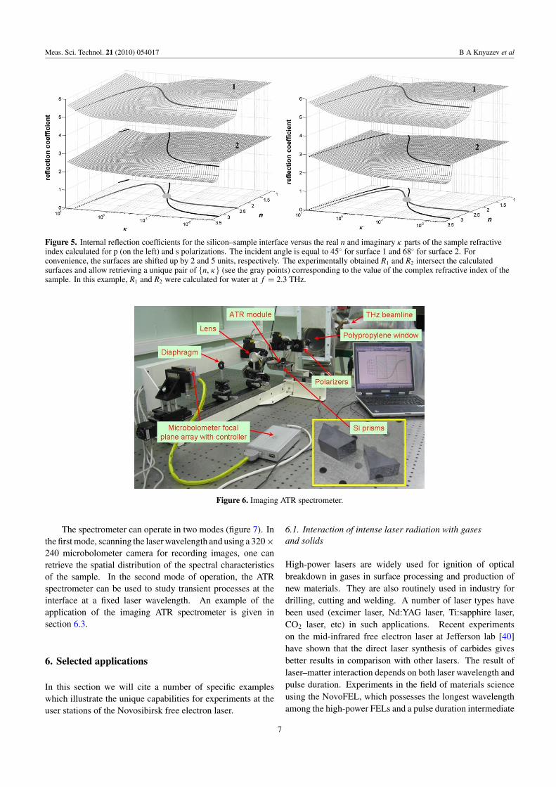
One of the problems of absorption spectroscopy is thehigh absorbance of many materials in the terahertz range. Forexample, most biological substances contain water, whichabsorbs terahertz radiation completely in a 10 μm layer.For highly absorbing substances, attenuated total reflectionspectroscopy [35, 36] is a solution. Using the low beamdivergence, 3 ×10⁻³ rad, first, we developed very simplesingle- and double-channel THz attenuated total reflection(ATR) spectrometers with a silicon prism as the ATR elementand without any other optical elements. The internal reflectioncoefficients for two radiation polarizations P = {p OR s} andtwo incident angles versus the imaginary and real parts ofthe sample refractive index are shown in figure 5. The largereflectance clearly demonstrates a great advantage of ATRspectroscopy in the study of strongly absorbing materials overclassic absorption spectroscopy. FEL tunability allows thedetermination of both the real and imaginary parts of thesample refractive index via solution of Fresnel equationsusing reflection coefficients obtained in two measurementsat different angles and/or polarizations and matching theresults to the pre-calculated matrices R1(n, κ; λ0, θ1, P1)
and R2(n, κ; λ0, θ2, P2). A more detailed numerical analysis[37] showed that the optimal experimental strategy for thedetermination of κ and n would be the measurement ofreflection for two different incident angles at p-polarizationof probe radiation.
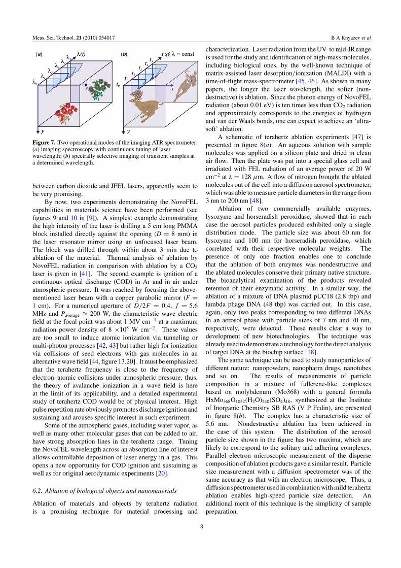
Drawing on this experience, we have developed thefirst imaging terahertz ATR. The existing imaging ATRspectrometers for the visible and near-infrared spectral ranges[38, 39] consist of a Fourier spectrometer with a CCD detector.They have a very limited field of view (∼1 mm2 or less),and cannot operate in a real-time mode. The tunability ofthe Novosibirsk FEL in a wide spectral range as well as avery low beam divergence enables the realization of anotherkind of imaging ATR spectrometer. A general view of thespectrometer is shown in figure 6. The highly directionalradiation of the free electron laser enters through a system oftwo polarizers into the ATR module at p- or s-polarization.Two mirrors controlled by stepper motors direct the radiationinto one of the replaceable silicon prisms through its sideedge. The beam impinges on the upper prism edge at an angleexceeding the critical angle of total reflection. A sample understudy (liquid, powder, film or solid) is attached to this edge.A system of two mirrors transmits the reflected radiation to anoptical system, which images the prism–sample interface ontothe microbolometer FPA. The field of view of the spectrometerreaches 200 mm2.
6
Meas. Sci. Technol. 21 (2010) 054017 B A Knyazev et al
Figure 5. Internal reflection coefficients for the silicon–sample interface versus the real n and imaginary κ parts of the sample refractiveindex calculated for p (on the left) and s polarizations. The incident angle is equal to 45◦ for surface 1 and 68◦ for surface 2. Forconvenience, the surfaces are shifted up by 2 and 5 units, respectively. The experimentally obtained R1 and R2 intersect the calculatedsurfaces and allow retrieving a unique pair of {n, κ} (see the gray points) corresponding to the value of the complex refractive index of thesample. In this example, R1 and R2 were calculated for water at f = 2.3 THz.
Figure 6. Imaging ATR spectrometer.
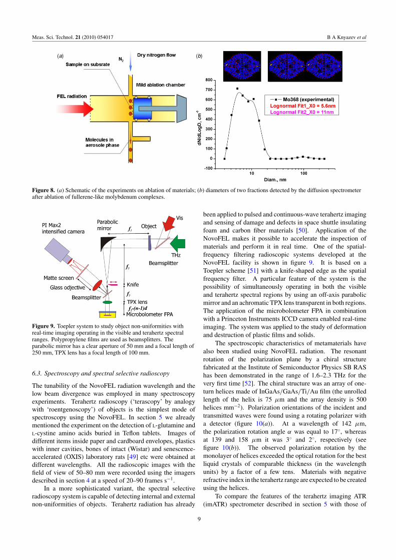
The spectrometer can operate in two modes (figure 7). Inthe first mode, scanning the laser wavelength and using a 320 ×240 microbolometer camera for recording images, one canretrieve the spatial distribution of the spectral characteristicsof the sample. In the second mode of operation, the ATRspectrometer can be used to study transient processes at theinterface at a fixed laser wavelength. An example of theapplication of the imaging ATR spectrometer is given insection 6.3.
6. Selected applications
In this section we will cite a number of specific exampleswhich illustrate the unique capabilities for experiments at theuser stations of the Novosibirsk free electron laser.
6.1. Interaction of intense laser radiation with gasesand solids
High-power lasers are widely used for ignition of opticalbreakdown in gases in surface processing and production ofnew materials. They are also routinely used in industry fordrilling, cutting and welding. A number of laser types havebeen used (excimer laser, Nd:YAG laser, Ti:sapphire laser,CO2 laser, etc) in such applications. Recent experimentson the mid-infrared free electron laser at Jefferson lab [40]have shown that the direct laser synthesis of carbides givesbetter results in comparison with other lasers. The result oflaser–matter interaction depends on both laser wavelength andpulse duration. Experiments in the field of materials scienceusing the NovoFEL, which possesses the longest wavelengthamong the high-power FELs and a pulse duration intermediate
7
Meas. Sci. Technol. 21 (2010) 054017 B A Knyazev et al
(a) (b)
Figure 7. Two operational modes of the imaging ATR spectrometer:(a) imaging spectroscopy with continuous tuning of laserwavelength; (b) spectrally selective imaging of transient samples ata determined wavelength.
between carbon dioxide and JFEL lasers, apparently seem tobe very promising.
By now, two experiments demonstrating the NovoFELcapabilities in materials science have been performed (seefigures 9 and 10 in [9]). A simplest example demonstratingthe high intensity of the laser is drilling a 5 cm long PMMAblock installed directly against the opening (D = 8 mm) inthe laser resonator mirror using an unfocused laser beam.The block was drilled through within about 3 min due toablation of the material. Thermal analysis of ablation byNovoFEL radiation in comparison with ablation by a CO2
laser is given in [41]. The second example is ignition of acontinuous optical discharge (COD) in Ar and in air underatmospheric pressure. It was reached by focusing the above-mentioned laser beam with a copper parabolic mirror (F =1 cm). For a numerical aperture of D/2F = 0.4, f = 5.6MHz and Paverage ≈ 200 W, the characteristic wave electricfield at the focal point was about 1 MV cm−1 at a maximumradiation power density of 8 ×10⁸ W cm−2. These valuesare too small to induce atomic ionization via tunneling ormulti-photon processes [42, 43] but rather high for ionizationvia collisions of seed electrons with gas molecules in analternative wave field [44, figure 13.20]. It must be emphasizedthat the terahertz frequency is close to the frequency ofelectron–atomic collisions under atmospheric pressure; thus,the theory of avalanche ionization in a wave field is hereat the limit of its applicability, and a detailed experimentalstudy of terahertz COD would be of physical interest. Highpulse repetition rate obviously promotes discharge ignition andsustaining and arouses specific interest in such experiment.
Some of the atmospheric gases, including water vapor, aswell as many other molecular gases that can be added to air,have strong absorption lines in the terahertz range. Tuningthe NovoFEL wavelength across an absorption line of interestallows controllable deposition of laser energy in a gas. Thisopens a new opportunity for COD ignition and sustaining aswell as for original aerodynamic experiments [20].
6.2. Ablation of biological objects and nanomaterials
Ablation of materials and objects by terahertz radiationis a promising technique for material processing and
characterization. Laser radiation from the UV- to mid-IR rangeis used for the study and identification of high-mass molecules,including biological ones, by the well-known technique ofmatrix-assisted laser desorption/ionization (MALDI) with atime-of-flight mass-spectrometer [45, 46]. As shown in manypapers, the longer the laser wavelength, the softer (non-destructive) is ablation. Since the photon energy of NovoFELradiation (about 0.01 eV) is ten times less than CO2 radiationand approximately corresponds to the energies of hydrogenand van der Waals bonds, one can expect to achieve an ‘ultra-soft’ ablation.
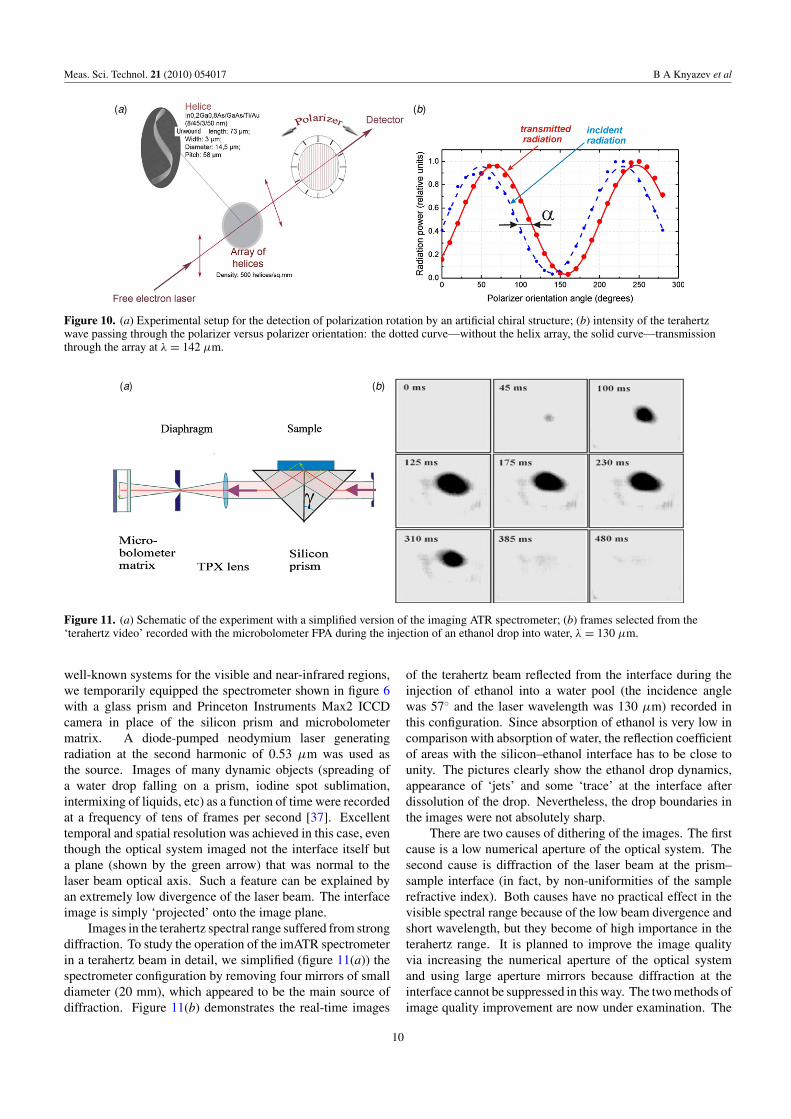
A schematic of terahertz ablation experiments [47] ispresented in figure 8(a). An aqueous solution with samplemolecules was applied on a silicon plate and dried in cleanair flow. Then the plate was put into a special glass cell andirradiated with FEL radiation of an average power of 20 Wcm−2 at λ = 128 μm. A flow of nitrogen brought the ablatedmolecules out of the cell into a diffusion aerosol spectrometer,which was able to measure particle diameters in the range from3 nm to 200 nm [48].
Ablation of two commercially available enzymes,lysozyme and horseradish peroxidase, showed that in eachcase the aerosol particles produced exhibited only a singledistribution mode. The particle size was about 60 nm forlysozyme and 100 nm for horseradish peroxidase, whichcorrelated with their respective molecular weights. Thepresence of only one fraction enables one to concludethat the ablation of both enzymes was nondestructive andthe ablated molecules conserve their primary native structure.The bioanalytical examination of the products revealedretention of their enzymatic activity. In a similar way, theablation of a mixture of DNA plasmid pUC18 (2.8 tbp) andlambda phage DNA (48 tbp) was carried out. In this case,again, only two peaks corresponding to two different DNAsin an aerosol phase with particle sizes of 7 nm and 70 nm,respectively, were detected. These results clear a way todevelopment of new biotechnologies. The technique wasalready used to demonstrate a technology for the direct analysisof target DNA at the biochip surface [18].
The same technique can be used to study nanoparticles ofdifferent nature: nanopowders, nanopharm drugs, nanotubesand so on. The results of measurements of particlecomposition in a mixture of fullerene-like complexesbased on molybdenum (Mo368) with a general formulaHxMo368O1032(H2O)240(SO4)48, synthesized at the Instituteof Inorganic Chemistry SB RAS (V P Fedin), are presentedin figure 8(b). The complex has a characteristic size of5.6 nm. Nondestructive ablation has been achieved inthe case of this system. The distribution of the aerosolparticle size shown in the figure has two maxima, which arelikely to correspond to the solitary and adhering complexes.Parallel electron microscopic measurement of the dispersecomposition of ablation products gave a similar result. Particlesize measurement with a diffusion spectrometer was of thesame accuracy as that with an electron microscope. Thus, adiffusion spectrometer used in combination with mild terahertzablation enables high-speed particle size detection. Anadditional merit of this technique is the simplicity of samplepreparation.
8
Meas. Sci. Technol. 21 (2010) 054017 B A Knyazev et al
(a) (b)
Figure 8. (a) Schematic of the experiments on ablation of materials; (b) diameters of two fractions detected by the diffusion spectrometerafter ablation of fullerene-like molybdenum complexes.
Figure 9. Toepler system to study object non-uniformities withreal-time imaging operating in the visible and terahertz spectralranges. Polypropylene films are used as beamsplitters. Theparabolic mirror has a clear aperture of 50 mm and a focal length of250 mm, TPX lens has a focal length of 100 mm.
6.3. Spectroscopy and spectral selective radioscopy
The tunability of the NovoFEL radiation wavelength and thelow beam divergence was employed in many spectroscopyexperiments. Terahertz radioscopy (‘terascopy’ by analogywith ‘roentgenoscopy’) of objects is the simplest mode ofspectroscopy using the NovoFEL. In section 5 we alreadymentioned the experiment on the detection of L-glutamine andL-cystine amino acids buried in Teflon tablets. Images ofdifferent items inside paper and cardboard envelopes, plasticswith inner cavities, bones of intact (Wistar) and senescence-accelerated (OXIS) laboratory rats [49] etc were obtained atdifferent wavelengths. All the radioscopic images with thefield of view of 50–80 mm were recorded using the imagersdescribed in section 4 at a speed of 20–90 frames s−1.
In a more sophisticated variant, the spectral selectiveradioscopy system is capable of detecting internal and externalnon-uniformities of objects. Terahertz radiation has already
been applied to pulsed and continuous-wave terahertz imagingand sensing of damage and defects in space shuttle insulatingfoam and carbon fiber materials [50]. Application of theNovoFEL makes it possible to accelerate the inspection ofmaterials and perform it in real time. One of the spatial-frequency filtering radioscopic systems developed at theNovoFEL facility is shown in figure 9. It is based on aToepler scheme [51] with a knife-shaped edge as the spatialfrequency filter. A particular feature of the system is thepossibility of simultaneously operating in both the visibleand terahertz spectral regions by using an off-axis parabolicmirror and an achromatic TPX lens transparent in both regions.The application of the microbolometer FPA in combinationwith a Princeton Instruments ICCD camera enabled real-timeimaging. The system was applied to the study of deformationand destruction of plastic films and solids.
The spectroscopic characteristics of metamaterials havealso been studied using NovoFEL radiation. The resonantrotation of the polarization plane by a chiral structurefabricated at the Institute of Semiconductor Physics SB RAShas been demonstrated in the range of 1.6–2.3 THz for thevery first time [52]. The chiral structure was an array of one-turn helices made of InGaAs/GaAs/Ti/Au film (the unrolledlength of the helix is 75 μm and the array density is 500helices mm−2). Polarization orientations of the incident andtransmitted waves were found using a rotating polarizer witha detector (figure 10(a)). At a wavelength of 142 μm,the polarization rotation angle α was equal to 17◦, whereasat 139 and 158 μm it was 3◦ and 2◦, respectively (seefigure 10(b)). The observed polarization rotation by themonolayer of helices exceeded the optical rotation for the bestliquid crystals of comparable thickness (in the wavelengthunits) by a factor of a few tens. Materials with negativerefractive index in the terahertz range are expected to be createdusing the helices.
To compare the features of the terahertz imaging ATR(imATR) spectrometer described in section 5 with those of
9
Meas. Sci. Technol. 21 (2010) 054017 B A Knyazev et al
(a) (b)
Figure 10. (a) Experimental setup for the detection of polarization rotation by an artificial chiral structure; (b) intensity of the terahertzwave passing through the polarizer versus polarizer orientation: the dotted curve—without the helix array, the solid curve—transmissionthrough the array at λ = 142 μm.
(a) (b)
Figure 11. (a) Schematic of the experiment with a simplified version of the imaging ATR spectrometer; (b) frames selected from the‘terahertz video’ recorded with the microbolometer FPA during the injection of an ethanol drop into water, λ = 130 μm.
well-known systems for the visible and near-infrared regions,we temporarily equipped the spectrometer shown in figure 6with a glass prism and Princeton Instruments Max2 ICCDcamera in place of the silicon prism and microbolometermatrix. A diode-pumped neodymium laser generatingradiation at the second harmonic of 0.53 μm was used asthe source. Images of many dynamic objects (spreading ofa water drop falling on a prism, iodine spot sublimation,intermixing of liquids, etc) as a function of time were recordedat a frequency of tens of frames per second [37]. Excellenttemporal and spatial resolution was achieved in this case, eventhough the optical system imaged not the interface itself buta plane (shown by the green arrow) that was normal to thelaser beam optical axis. Such a feature can be explained byan extremely low divergence of the laser beam. The interfaceimage is simply ‘projected’ onto the image plane.
Images in the terahertz spectral range suffered from strongdiffraction. To study the operation of the imATR spectrometerin a terahertz beam in detail, we simplified (figure 11(a)) thespectrometer configuration by removing four mirrors of smalldiameter (20 mm), which appeared to be the main source ofdiffraction. Figure 11(b) demonstrates the real-time images
of the terahertz beam reflected from the interface during theinjection of ethanol into a water pool (the incidence anglewas 57◦ and the laser wavelength was 130 μm) recorded inthis configuration. Since absorption of ethanol is very low incomparison with absorption of water, the reflection coefficientof areas with the silicon–ethanol interface has to be close tounity. The pictures clearly show the ethanol drop dynamics,appearance of ‘jets’ and some ‘trace’ at the interface afterdissolution of the drop. Nevertheless, the drop boundaries inthe images were not absolutely sharp.
There are two causes of dithering of the images. The firstcause is a low numerical aperture of the optical system. Thesecond cause is diffraction of the laser beam at the prism–sample interface (in fact, by non-uniformities of the samplerefractive index). Both causes have no practical effect in thevisible spectral range because of the low beam divergence andshort wavelength, but they become of high importance in theterahertz range. It is planned to improve the image qualityvia increasing the numerical aperture of the optical systemand using large aperture mirrors because diffraction at theinterface cannot be suppressed in this way. The two methods ofimage quality improvement are now under examination. The
10
Meas. Sci. Technol. 21 (2010) 054017 B A Knyazev et al
first method is recording a sequence of interface images viafast moving the imager along the optical axis, which enablesspanning the image planes over all parts of the interface, withfollowing computer reconstruction of the whole image. Adrawback of this method is a decrease in the time resolution.The second method is splitting the laser beam into an objectbeam and a reference one and recording a hologram, whichenables digital reconstruction of the interface image.
Another spectroscopy technique, which seems to bevery promising for the study of thin films and conductor–dielectric interfaces using the NovoFEL as a THz source, issurface plasmon spectroscopy (see, e.g., [53]). Laser beammonochromaticity and tunability enable the implementationof experimental configurations quite different from standardexperiments with surface plasmon polariton (SPP), in whichthe time-domain spectroscopy technique is commonly used(see [54, 55]). Due to the high power of NovoFEL radiation,real-time images of the evanescent wave of terahertz SPP havebeen obtained using the microbolometer camera. Resultsof this experiment as well as of experiments on surfaceplasmon transport along gold films (clear and covered withnanoparticles and DNA) will be published elsewhere.
6.4. Holography, tomography and interferometry
The feasibility of terahertz spectral selective holographyand tomography has been demonstrated in a number ofexperiments [34]. Real-time terahertz imaging of objectsilluminated with unidirectional and diffuse terahertz beamshas been examined. Speckle patterns, which were observedin the THz region for the very first time, were used for thedemonstration of terahertz speckle photography [56, 57]. Alaser beam illuminated a diffusely scattering spinning object.The scattered radiation illuminated another object, whoseimage was recorded with the microbolometer ‘video camera’.The speckle pattern, moving across the image plane, enabledthe determination of mechanical characteristics of the rotatingobject. The rotation axis position, instantaneous rotation speedand damping decrement were found from the video, thoughthe object under study was out of the field of view of therecording system. Since a wavelength in the terahertz rangeis about 200 times longer than a wavelength in the visiblerange, terahertz speckle metrology (speckle photography andspeckle interferometry) must be promising for measurementsin the corresponding dimension scale.
Another effect, which can be applied for metrology, is theTalbot effect [58]. The Talbot effect states that any amplitudedistribution, which is a periodic function of x and y, will alsobe periodic in the direction of propagation (z) when z is amultiple of the so-called Talbot distance [59]. This effect iswell known in visible light and in quantum mechanics buthas not been described in the terahertz range yet. We haverecently observed this effect using NovoFEL radiation. Theexperimental results will be published soon.
By now, terahertz tomography has been demonstratedusing wideband picosecond pulses [60]. A very special digitalmethod was used for 2D and 3D image reconstruction. WithNovoFEL radiation, classic tomographic schemes can be used
in the terahertz range. The crucial difference between visibleand terahertz tomography is the very strong diffraction in thesecond case, which requires development of more complexreconstruction techniques. Simple Gabor holograms havealready been recorded at the facility and further experimentsare in progress.
7. Concluding remarks
Invention of novel radiation sources was usually followed byimplementation of the new spectral range into practice. Forexample, the period between the discovery of x-rays and theiremployment in medicine was about 25 years. Development ofterahertz sources started about 20 years ago. We can expectreal implementation of ‘T-rays’ in the near future. The resultsobtained at the NovoFEL user facility have demonstrateda number of techniques based on monochromatic terahertzsources and their possible application. The development ofnew monochromatic terahertz sources (compact free electronlasers [61], quantum cascade lasers [62], etc) will allowimparting new methods and techniques for employment inmedicine, materials science, industry, metrology and manyother fields.
Acknowledgments
This work was supported in part by grants from the RussianFoundation for Basic Research (07-02-13547, 09-02-12158and 09-02-12121) and Siberian Branch of Russian Academyof Science (Integration grant #89). The authors are indebtedto the members of the NovoFEL team and NovoFEL usersV S Cherkassky, E N Chesnokov, Yu V Chugui, M ADem’yanenko, D G Esaev, N G Gavrilov, V V Gerasimov,Ya V Getmanov, T N Goryachkovskaya, E I Kolobanov,A S Kozlov, V V Kubarev, S B Malyshkin, A N Matveenko,L E Medvedev, S V Miginsky, L A Mironenko, E V Naumova,V K Ovchar, S E Peltek, A K Petrov, V M Popik, V YaPrinz, T V Salikova, M A Scheglov, S S Serednyakov, O AShevchenko, A N Skrinsky, M F Stupak, M G Vlasenko, V IYakovlev and many others for their significant contribution tothe development of the NovoFEL facility and instrumentationas well as for kind permission to cite their results in this paper.
References
[1] Mickan S P and Zhang X-C 2003 T-ray sensing and imagingInt. J. High Speed Electron. Syst. 13 601–76
[2] Carr G L, Martin M C, McKinney W R, Jordan K, Neil G Rand Williams G P 2002 High-power terahertz radiationfrom relativistic electrons Nature 420 153–6
[3] Schwettman H A, Smith T I and Swent R L 1996 Status of theStanford Picosecond FEL Center Nucl. Instrum. MethodsPhys. Res. A 375 662–3
[4] Ramian G and Elias L 1988 The new UCSB compactfar-infrared FEL Nucl. Instrum. Methods Phys. Res.A 272 81–8
[5] van der Meer A F G and van der Wiel M J 1997 Mid-IR FELuser facility FELIX Appl. Spectrosc. 51 574–5
[6] Nishimori N, Hajima R, Nagai R and Minehara E J 2001 Highextraction efficiency observed at the JAERI free-electronlaser Nucl. Instrum. Methods Phys. Res. A 475 266–9
11
Meas. Sci. Technol. 21 (2010) 054017 B A Knyazev et al
[7] Ciocci F, Bartolini R, Doria A, Gallerano G P, Giovenale E,Kimmitt M F, Messina G and Renieri A 1993 Operationof a compact free-electron laser in the millimeter-waveregion with a bunched electron beam Phys. Rev. Lett.70 928–31
[8] Jeong Y U et al 2001 First lasing of the KAERI compactfar-infrared free-electron laser driven by a magnetron-basedmicrotron Nucl. Instrum. Methods Phys. Res. A 475 47–50
[9] Neil G R et al 2000 Sustained kilowatt lasing in a free-electronlaser with same-cell energy recovery Phys. Rev. Lett.84 662–5
[10] Gavrilov N G et al 2007 Status of the Novosibirsk high-powerterahertz FEL Proc. Int. Conf. on Free Electron Lasers(Liverpool, UK) p 5 Paper TUOD01
[11] Minehara E J 2002 Highly efficient and high-power industrialFELs driven by a compact, stand-alone and zero-boil-offsuperconducting RF linac Nucl. Instrum. Methods Phys.Res. A 483 8–13
[12] Antokhin E A et al 2004 First lasing at the high-power freeelectron laser at Siberian center for photochemistry researchNucl. Instrum. Meth. Phys. Res. A 528 15–8
[13] Marshall T C 1985 Free-Electron Lasers (New York:Macmillan)
[14] Kubarev V V, Persov B Z, Vinokurov N A and Davidov A V2004 Optical resonator of powerful free-electron laser Nucl.Instrum. Methods Phys. Res. A 528 199–202
[15] Kubarev V V, Kolobanov E I, Kulipanov G N, MatveenkoA N, Medvedev L E, Salikova T V, Scheglov M A,Serednyakov S S and Vinokurov N A 2009 Modulationinstability at the Novosibirsk Terahertz free electron laser:study and suppression Proc. 34th Int. Conf. on Infrared,Millimeter and Terahertz Waves (Busan, Korea, 21–25September 2009) paper W5E62.0429
[16] Cherkassky V S, Knyazev B A, Kulipanov G N, MatveenkoA N, Rudych P D and Vinokurov N A 2007 Study ofpolarizer characteristics with a high-power terahertz freeelectron laser Int. J. Infrared Millim. Waves 28 219–22
[17] Knyazev B A, Kulipanov G N and Vinokurov N A 2007Optical components, detectors and cameras for user-stationoptical systems at a high-power terahertz FEL J. KoreanPhys. Soc. 51 409–15
[18] Kulipanov G N et al 2008 Research highlights from theNovosibirsk 400 W average power THz FEL Terahertz Sci.Technol. 1 107–25http://www.thznetwork.org.cn/Journal/shownews1.asp?id=2
[19] Serednyakov S S, Makashov E V, Palagin K S and KubarevV V 2007 Control and diagnostic system of NovosibirskFEL radiation Proc. 29th Int. Conf. on Free Electron Lasers(Novosibirsk, Russia) pp 111–3 http://accelconf.web.cern.ch/accelconf/f07/PAPERS/MOPPH043.PDF
[20] Fomin V M, Knyazev B A, Kubarev V V, Kulipanov G N,Scheglov M A, Vinokurov N A, Yakovlev V I and PetrovA K 2007 Research opportunities at terahertz Novosibirskfree electron laser Proc. Int. Conf. on the Methods ofAerophysical Research (Novosibirsk, Russia, 5–10 February2007) (Novosibrisk: Publ. House ‘Parallel’) pt 2, p 71
[21] Vinokurov N A, Zhigach S A, Knyazev B A, Konysheva A V,Kulipanov G N, Merzhievsky L A, Polskikh I Aand Cherkassky V S 2007 Diffractive optical elements andquasioptical schemes on a high-power terahertzfree-electron laser Radiophys. Quantum Electron.50 803–12
[22] Knyazev B A and Cherkassky V S 2006 Reflective diffractionoptical elements and their application to controlfree-electron-laser terahertz radiation Vestn. NovosibirskState Univ. Phys. 1 (2) 3–22 (in Russian)http://www.phys.nsu.ru/vestnik/
[23] Vedernikov V M et al 2009 Transmissive diffractive elementsfor the terahertz spectral range Proc. 9th Int. Symp. on
Measurement Technology and Intelligent Instrumentsed Yu V Chugui vol 2 pp 366–70
[24] Gerasimov V V, Knyazev B A, Rudych P D andCherkassky V S 2007 Fresnel reflection in opticalcomponents and detectors for the terahertz frequency bandInstrum. Exp. Tech. 50 524–9
[25] Jiang Z and Zhang X-C 2003 Free-space electro-optictechniques Sensing with Terahertz Radiationed D Mittelman (Berlin: Springer) pp 155–87
[26] Kolobanov E I et al 2005 Highly sensitive fast Schottky-diodedetectors in experiments on Novosibirsk free electron laserProc. Joint 30th Int. Conf. on Infrared and MillimeterWaves and 13th Int. Conf. on Terahertz Electronics(Williamsburg, VA, USA, 19–23 September 2005) vol 2(Piscataway, NJ: IEEE) p 154
[27] Kuryshev G L et al 1998 Medical infrared imaging systembased on a focal plane array for 2.8–3.05 spectral rangeOptoelectron. Instrum. Data Process. no 4 5–10
[28] Dem’yanenko M A, Esaev D G, Knyazev B A, Kulipanov G Nand Vinokurov N A 2008 Imaging with a 90 frames s−1
microbolometer focal plane array and high-power terahertzfree electron laser Appl. Phys. Lett. 92 131116
[29] Knyazev B A and Kubarev V V 2009 Wide-field imagingusing a tunable terahertz free electron laser and a thermalimage plate Infrared Phys. Technol. 52 14–8
[30] Vinokurov N A, Knyazev B A, Kulipanov G N,Matveenko A N, Popik V M, Cherkassky V Sand Shcheglov M A 2007 Visualization of radiation from ahigh-power terahertz free electron laser with athermosensitive interferometer Tech. Phys. 52 911–9
[31] http://www.macken.com/thermal.shtml[32] Dem’yanenko M A, Fomin B I, Ovsyuk V N, Marchishin I V,
Parm I O, Vasil’ieva L L and Shashkin V V 2005 Uncooled160 × 120 microbolometer IR FPA based on sol–gel VOx
Proc. SPIE 5957 59571R.1–59571R.8[33] Kubarev V V, Makashov E V, Palagin K S, Serednyakov S S
and Fedotov M G 2007 Power meters and 2D beam imagingsystems on the Novosibirsk Terahertz Free Electron LaserConf. Digest of the Joint 32nd Int. Conf. on Infrared andMillimetre Waves, and 15th Int. Conf. on TerahertzElectronics (Cardiff, UK, 3–7 September 2007) vol 1ed M J Griffin et al (Piscataway, NJ: IEEE) pp 249–50
[34] Cherkassky V S, Gerasimov V V, Ivanov G M, Knyazev B A,Kulipanov G N, Lukyanchikov L A, Merzhievsky L Aand Vinokurov N A 2007 Techniques for introscopy ofcondensed matter in terahertz spectral region Nucl. Instrum.Methods Phys. Res. A 575 63–7
[35] Harrick N J 1967 Internal Reflection Spectroscopy (New York:Wiley)
[36] Gerasimov V V and Knyazev B A 2008 Features of attenuatedtotal reflection spectroscopy in the terahertz region Vestn.Novosibirsk State Univ. Phys. 3 97–112 (in Russian)http://www.phys.nsu.ru/vestnik/
[37] Gerasimov V V, Knyazev B A and Cherkassky V S 2010Spectral-selective real-time images of objects in the modeof attenuated total reflection in visible and terahertz regionsOpt. Spectrosc. (at press)
[38] Kazarian S G and Van der Weerd J 2008 Simultaneous FTIRspectroscopic imaging and visible photography to monitortablet dissolution and drug release Pharm. Res. 25 853–60
[39] Burka E M and Curbelo R 2000 Imaging ATR spectrometerUS Patent No 6.141 100
[40] Schaaf P, Kahle M and Carpene E 2005 Reactive lasersynthesis of carbides and nitrides Appl. Surf. Sci.247 607–15
[41] Zakharov L A, Bulgakova N M, Onischuk A A, Baklanov A Mand Petrov A K 2006 Thermal analysis of polymethylmethacrylate ablation by pulsed IR lasers Proc. SPIE6263 62630S
12

Meas. Sci. Technol. 21 (2010) 054017 B A Knyazev et al
[42] Popov V S 2004 Tunnel and multiphoton ionization of atomsand ions in a strong laser field (Keldysh theory) Phys.–Usp.47 855–86
[43] Delone N B and Krainov V P 1985 Atoms in Strong LightFields (Berlin: Springer)
[44] Raiser Yu P 1987 Gas Discharge Physics (Moscow: Nauka)(in Russian)
[45] Karas M, Bachmann D, Bahr U and Hillenkamp F 1987Matrix-assisted ultraviolet laser desorption of non-volatilecompounds Int. J. Mass Spectrom. Ion Process.78 53–68
[46] Tanaka K, Waki H, Ido Y, Akita S, Yoshida Y and Yoshida T1988 Protein and polymer analyses up to m/z 100 000 bylaser ionization time-of-flight mass spectrometry RapidCommun. Mass Spectrom. 2 151–3
[47] Petrov A K, Kozlov A S, Malyshkin S B, Taraban M B,Popik V M, Scheglov M A, Goriachkovskaya T Nand Peltek S E 2007 Nondestructive transfer of complexmolecular systems of various origins into aerosol phase bymeans of submillimeter irradiation of free-electron laser(FEL) of the Siberian center for photochemical researchNucl. Instrum. Methods Phys. Res. A 575 68–71
[48] Julanov Y V, Lushnikov A A and Zagyanov V A 2002Diffusion aerosol spectrometer Atmos. Res. 62 295–302
[49] Gonchar A M, Gerasimov V V, Gavrilov N G andKnyazev B A 2007 Spectroscopy and spectrally resolvedradioscopy of biological substances using terahertz freeelectron laser radiation Proc. 29th Int. Conf. on FreeElectron Lasers (Novosibirsk, Russia) pp 86–8 paperMOPPH031 http://accelconf.web.cern.ch/accelconf/f07/PAPERS/MOPPH031.PDF
[50] Redo-Sanchez A, Karpowicz N, Xu J and Zhang X-C 2006Proc. 4th Int. Workshop on Ultrasonic and AdvancedMethods for Nondestructive Testing and MaterialCharacterization (UMass Dartmouth, N Dartmouth, MA,19 June 2006) pp 67–78
[51] Settles G S 2001 Schlieren and Shadowgraph Techniques:Visualizing Phenomena in Transparent Media (Berlin:Springer)
[52] Naumova E V, Prinz V Yu, Seleznev V A, Golod S V,Kubarev V V, Knyazev B A, Kulipanov G N,Kuznetsov S A, Kalinin P V and Vinokurov N A 2006Polarization rotation of THz radiation by an array of helicesProc. Joint 31st Int. Conf. on Infrared and Millimeter Wavesand 14th Int. Conf. on Terahertz Electronics (Shanghai,China, 18–22 September) p 1 paper WedB4-3
[53] Kawata S 2001 Near-Field Optics and Surface PlasmonPolaritons (Topics in Applied Physics) (Berlin: Springer)
[54] Grischkowsky D, Keiding S, van Exter M and Fattinger Ch1990 Far-infrared time-domain spectroscopy with terahertzbeams of dielectrics and semiconductors J. Opt. Soc. Am. B7 2006–15
[55] Martl M, Darmo J, Unterrainer K and Gornik E 2009Excitation of terahertz surface plasmon polaritons on etchedgroove gratings J. Opt. Soc. Am. B 26 554–8
[56] Chashchina O I, Knyazev B A, Kulipanov G N andVinokurov N A 2009 Real-time speckle metrology usingterahertz free electron laser radiation Nucl. Instrum.Methods Phys. Res. A 603 50–1
[57] Vinokurov N A, Dem’yanenko M A, Esaev D G,Knyazev B A, Kulipanov G N, Chashchina O Iand Cherkasskii V S 2009 Speckle pattern of the images ofobjects exposed to monochromatic coherent terahertzradiation Quantum Electron. 39 481–6
[58] Talbot H F 1836 Facts relating to optical science Phil. Mag.401–7
[59] Winthrop J T and Worthington C R 1964 Theory of Fresnelimages: I. Plane periodic objects in monochromatic lightJ. Opt. Soc. Am. 55 373–80
[60] Wang S and Zhang X-C 2004 Pulsed terahertz tomographyJ. Phys. D: Appl. Phys. 37 R1–36
[61] Shevchenko O A, Matveenko A N and Vinokurov N A 2008Compact ring FEL as a source of high-power infraredradiation Nucl. Instrum. Methods Phys. Res. A 603 42–5
[62] Williams B, Kumar S, Hu Q and Reno J 2005 Operation ofterahertz quantum-cascade lasers at 164 K in pulsed modeand at 117 K in continuous-wave mode Opt. Express13 3331–9
13