nt39016 d - newhaven display international, inc.newhavendisplay.com/app_notes/nt39016d.pdf ·...
TRANSCRIPT

1
NT39016 D One Chip TFT LCD Driver IC with Timing Controller
For S960xG240 TFT LCD
V0.7
Preliminary Spec.
Preliminary Spec. for NT39016D TFT LCD Driver
With respect to the information represented in this document, Novatek makes no warranty, expressed or implied, including the warranties of merchantability, fitness for a particular purpose, non-infringement, or assumes any legal liability or responsibility for the accuracy, completeness, or usefulness of any such information.
2 Version 0.7 Mar 10,2008
Revise History
NT39016 Specification Revision History
Version Content Page Date
0.7 Modify DC Electrical Characteristics 29、、、、28 2008/3/10
0.6 Modify pin description Remove CPMPDB function
8 14
2008/2/18
0.5 Modify Analog Supply Voltage 29 2008/2/4
0.4 Modify 3-Wire Control Register 12 2008/1/14
0.3 Modify STBYB initial value Modify Digital Operating Current value Modify Analog Operating Current value
14 28 29
2007/11/26
0.2 Source Driver Output Timing Diagram 33 2007/11/16
0.1 New Spec. -- 2007/10/22

Preliminary Spec. for NT39016D TFT LCD Driver
With respect to the information represented in this document, Novatek makes no warranty, expressed or implied, including the warranties of merchantability, fitness for a particular purpose, non-infringement, or assumes any legal liability or responsibility for the accuracy, completeness, or usefulness of any such information.
3 Version 0.7 Mar 10,2008
Index
Revise History ................................................................................................................................................... 2 Index ................................................................................................................................................................. 3 Features ............................................................................................................................................................ 4 General Description ........................................................................................................................................... 4 Function Block Diagram ..................................................................................................................................... 5
System Block Diagram................................................................................................................................ 5 Charge Pump Circuit Block Diagram ........................................................................................................... 6
Pad Sequence (Bump Side)............................................................................................................................... 7 Pad Description ................................................................................................................................................. 8 3-Wire Serial Port Interface (Default Register Map) .......................................................................................... 11
3-Wire Command Format.......................................................................................................................... 11 3-Wire Control Registers (Default)............................................................................................................. 12 3-Wire Registers Function Description ...................................................................................................... 14
Function Description ........................................................................................................................................ 23 Power On/Off Sequence ........................................................................................................................... 23 External Reset (RSTB).............................................................................................................................. 23 Input Data VS Output Voltage ................................................................................................................... 24 Input Data and Output Voltage Reference Table (VSET = “0”)................................................................... 25
Data Input Format............................................................................................................................................ 26 1. RGB input Data format.......................................................................................................................... 26 2. YUV input Data format .......................................................................................................................... 26 3. CCIR_656 Mode Data format ................................................................................................................ 26 4. Data Active Area ................................................................................................................................... 26 5. YUV_601/656 to RGB conversion ......................................................................................................... 27 6. Brightness / Contrast Adjustment .......................................................................................................... 27
Absolute Maximum Ratings.............................................................................................................................. 28 DC Electrical Characteristics............................................................................................................................ 28 AC Electrical Characteristics ............................................................................................................................ 30 Timing Table.................................................................................................................................................... 31
CCIR601 Mode A/B * ................................................................................................................................ 31 CCIR656 Mode A/B * ................................................................................................................................ 31 8 Bit RGB 960 CH Mode ........................................................................................................................... 31 24 Bit RGB Mode (@ SEL[3:0] = 1100 or 1101) ........................................................................................ 31
Timing Diagram ............................................................................................................................................... 32 Clock and Data Input Timing Diagram ....................................................................................................... 32 3-Wire Timing Diagram ............................................................................................................................. 32 Source Driver Output Timing Diagram....................................................................................................... 33 Gate Driver Output Timing Diagram .......................................................................................................... 33 Vertical Timing Diagram (HV Mode) .......................................................................................................... 34 Vertical Timing Diagram (DE Mode) .......................................................................................................... 34 Input Data Timing (24 bit RGB mode for 960 x 240 @ SEL[3:0] = 1100b) .................................................. 39
Pad Location.................................................................................................................................................... 36 Alignment Mark................................................................................................................................................ 37 Pad Information ............................................................................................................................................... 37 Application Notes............................................................................................................................................. 38
PWM for LED Backlight Control ................................................................................................................ 38 Appendix A: Pad Coordinate ............................................................................................................................ 39

Preliminary Spec. for NT39016D TFT LCD Driver
With respect to the information represented in this document, Novatek makes no warranty, expressed or implied, including the warranties of merchantability, fitness for a particular purpose, non-infringement, or assumes any legal liability or responsibility for the accuracy, completeness, or usefulness of any such information.
4 Version 0.7 Mar 10,2008
Features
� One-Chip solution for 960 x 240 dot TFT LCD Driver
� 8-bit resolution 256 gray scale with Dithering
� Support 8-bit / 24-bit digital (RGB) or CCIR_601/656 input timing
� Support two sets of 3-Wire commands for internal parameters setting
� Build-In DC2DC power supplies (VGH/VGL/VCOMAC/VCOMDC voltage supply)
� Configurable color filter type for both Delta and Stripe type
� 3.0 ~ 3.6V digital supply voltage with Build-In 1.8V LDO for internal circuit
� 3.0 ~ 3.6V charge pump supply voltage
� Configurable VCOMAC : 4.6V~6.1V
� Configurable VCOMDC : 1.0V~2.26V
� Source output deviation: 20mV(max)
� Source output settling time: 30uS(max)
� Operating frequency: 30MHz(max)
� Right/Left shift, Up and Down scan function selectable
� Support VCOM swing driving output
� Support Cs on Common structure
� Build-In PWM circuit for LED Back-light
� Support stand-by mode for low power consumption
� Frame / One Line / Two Line Inversion driving method selectable
� Built-in Auto Test Pattern
� COG package
General Description
NT39016 is a single-chip solution for 960x240 dot color TFT-LCD panel, which integrated source driver, gate driver, timing controller, power generator and 3-wire interface for system function control.
With highly integration technology, NT39016 integrate 960 channels source driver and 240 channels gate driver on single silicon. Data Input support 8 bit digital image data with standard CCIR601/656, serial 8-bit RGB data format or parallel 24-bit RGB data format. Source outputs support 8-bit resolution (256 gray scales) with dithering function on. Custom parameters can be set by using 3-wire commands. Special circuit architecture is designed for system lower power dissipation.
NT39016 is designed for wide voltage supply range and small output deviation for better display quality. Power dissipation for internal 5 sections reference voltage resistors for 64-level gamma resistors are also concerned. Supporting multiple input timings make this chip more suitable to various applications of small size TFT-LCD panel.

Preliminary Spec. for NT39016D TFT LCD Driver
With respect to the information represented in this document, Novatek makes no warranty, expressed or implied, including the warranties of merchantability, fitness for a particular purpose, non-infringement, or assumes any legal liability or responsibility for the accuracy, completeness, or usefulness of any such information.
5 Version 0.7 Mar 10,2008
Function Block Diagram
System Block Diagram

Preliminary Spec. for NT39016D TFT LCD Driver
With respect to the information represented in this document, Novatek makes no warranty, expressed or implied, including the warranties of merchantability, fitness for a particular purpose, non-infringement, or assumes any legal liability or responsibility for the accuracy, completeness, or usefulness of any such information.
6 Version 0.7 Mar 10,2008
Charge Pump Circuit Block Diagram
NT39016 built in charge pump circuit for gate driver VGH / VGL voltage and panel VCOMAC/VCOMDC voltage. Following block diagram illustrate how the charge pump circuit works.
<Value of wiring resistance and Cap.>
Pin name Resistor of wiring (ohm) Cap no. CAP (uF)
C1P < 10
C1M < 10 C1
C2P < 10
C2M < 10 C2
C3P < 10
C3M < 10 C3
C4P < 10
C4M < 10 C4
C1AP < 10
C1AM < 10 C1A
>1uF
*Note: Others Cap. Suggest value > 4.7 uF Schottky diode turn-on voltage=0.2V
Preliminary Spec. for NT39016D TFT LCD Driver
With respect to the information represented in this document, Novatek makes no warranty, expressed or implied, including the warranties of merchantability, fitness for a particular purpose, non-infringement, or assumes any legal liability or responsibility for the accuracy, completeness, or usefulness of any such information.
7 Version 0.7 Mar 10,2008
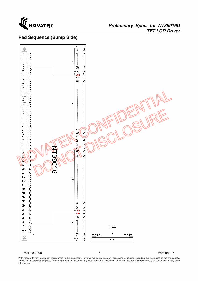
Pad Sequence (Bump Side)

Preliminary Spec. for NT39016D TFT LCD Driver
With respect to the information represented in this document, Novatek makes no warranty, expressed or implied, including the warranties of merchantability, fitness for a particular purpose, non-infringement, or assumes any legal liability or responsibility for the accuracy, completeness, or usefulness of any such information.
8 Version 0.7 Mar 10,2008
Pad Description
NT39016 Pad Description:
Designation I/O Description
DIN[23..0] I
Data Input. For 8/24-bit digital (RGB) or 8-bit CCIR601/656 image data input
8-bit mode: DIN7: MSB; DIN0: LSB; the remainder should be connect to GND.
24-bit mode: DIN[7:0] = R[7:0] data; DIN[15:8] = G[7:0] data; DIN[23:16] = B[7:0] data.
For 18bit RGB interface, connect two LSB bits of all the R/G/B data bus to GND.
CLKIN I Clock for Input Data. Data latched at rising/falling edge of this signal. Default Negative polarity.
HSD I Horizontal Sync input. Default Negative polarity, can be change by HSDPOL register.
VSD I Vertical Sync input. Default Negative polarity, can be change by VSDPOL register.
DEN I
(Pull Low)
Data Input Enable. Active High to enable the data input Bus under “DE Mode”. Normally pull low.
DATSEQ O Data sequence control pin for external T-CON. Output “1”: for Odd line, “0”: for Even line
POL O Frame polarity output. Amplitude of signal is from 0V to 3.3V.
V1 ~ V7 I/O
Gamma correction reference voltage.
When VSET=”1” is used. The voltage of pins V1 ~ V7 must be swing and must be
AVDD-0.1V > V1 > V2 > V3 V5 > V6 > V7 > AGND+0.1V when POL=”1” and
AGND+0.1V < V1’ < V2’ < V3’ V5’ < V6’ < V7’ < AVDD-0.1V when POL=”0”,
Where V1-V2=V2’-V1’, V2-V3=V3’-V2’, …V5-V6=V6’-V5’, V6-V7=V7’-V6’.
Note: V1~V7 must be supplied voltage external when VSET=”1”. Vx is external power of positive polarity and Vx’ is external power of negative polarity
SPENB I
(Pull High)
3-Wire Communication Enable. Active Low. Normally pull high.
Please pull high or floating under PINCTLB=0 mode.
SPDA I/O 3-Wire Communication Data input/output.
SPCK I 3-Wire Communication Clock input. Rising edge latch.
SPSW I
(Pull Low)
3-Wire register map select.
”0” for default 3-Wire register map, “1” for optional 3-Wire register map.
RSTB I
(Pull High)
Global reset pin. Active Low to enter Reset State. Suggest connecting with a RC reset circuit for stability. Normally pull high.
PINCTLB I
(Pull High)
Enable pin control function. Normally pull high
PINCTLB = “0”, Enable pin control function. TP0~14 and TP16~18 active as input pin for function control propose. Refer to the TP0~18 description for more information.
PINCTLB = “1”, Default mode. TP0~14 and TP16~18 active as unknown state ; Don’t connect TP0~14 and TP16~18 to any state under this mode.
Note: The 3-wire control register will be disabled under PINCTLB = 0 mode.
SO1~SO960 O Source Driver Output Signals.
GO1~GO240 O Gate Driver Output Signals.
ALIGN_T/B M For assembly alignment.
TP15 I
Charge pump on/off control pin.TP15=CPMPDB
CPMPDB = “0”, internal charge pump will be shut down
CPMPDB = “1”, internal charge pump normal operating
TP15 active as input pin under any state of PINCTLB.
If floating TP15,the charge pump will turn off
TP0~14
TP16~18
T
I
TEST Pin / Function control pin.
When PINCTLB = “1”, TP0~14, TP16~18 act as test pin. Floating those pins for normal operation.
When PINCTLB = “0”, TP0~14, TP16~18 act as function control input pin. All the input pin should be connect to GND or VDD. Floating those pins will result in input unknown problem.
VPSW I
(Pull Low)
Voltage control switch. Normally pull low.
VPSW = “0” .Default mode. VGH、VGL、VCOMAC and VCOMDC active as normal use and
control by 3-wire.
VPSW = “1”.Voltage fix mode. VGH = 18V、VGL = -7V 、VCOMAC = 5.4V and VCOMDC
Preliminary Spec. for NT39016D TFT LCD Driver
With respect to the information represented in this document, Novatek makes no warranty, expressed or implied, including the warranties of merchantability, fitness for a particular purpose, non-infringement, or assumes any legal liability or responsibility for the accuracy, completeness, or usefulness of any such information.
9 Version 0.7 Mar 10,2008
= 1.7V. Under the mode voltage can't control by 3-wire
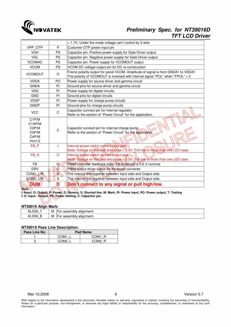
VPP_OTP P Customer OTP power input pin
VGH PS Capacitor pin. Positive power supply for Gate Driver output
VGL PS Capacitor pin. Negative power supply for Gate Driver output
VCOMAC PS Capacitor pin. Power supply for VCOMOUT output
VCOM PS VCOM DC voltage output pin for DC re-construction
VCOMOUT O Frame polarity output for panel VCOM. Amplitude of signal is from GNDA1 to VDDA1
The polarity of VCOMOUT is inversed with internal signal “POL” when “FPOL” = 0
VDDA PO Power supply for source driver and gamma circuit
GNDA PI Ground pins for source driver and gamma circuit
VDD PI Power supply for digital circuits
GND PI Ground pins for digital circuits
VDDP PI Power supply for charge pump circuits
GNDP PI Ground pins for charge pump circuits
VCC C Capacitor connect pin for internal regulator
Refer to the section of “Power Circuit” for the application.
C1P/M
C1AP/M
C2P/M
C3P/M
C4P/M
Vint1/2
C Capacitor connect pin for internal charge pump
Refer to the section of “Power Circuit” for the application.
FB_P I Internal power switch current input pad.
Note: Voltage on this pad should be < 5.5V. Pull low in more than one LED case.
FB_N O Internal power switch current output pad.
Note: Voltage on this pad should be < 5.5V. Pull low in more than one LED case.
FB VI PWM controller feedback input. FB threshold is 0.6 V nominal
DRV O PWM output driver signal for the boost converter
COM1_L/R S The internal link together between input side and Output side.
COM2_L/R S The internal link together between input side and Output side.
DUM D Don’t connect to any signal or pull high/low. Note: I: Input, O: Output, P: Power, D: Dummy, S: Shorted line, M: Mark, PI: Power input, PO: Power output, T: Testing I/ O: Input / Output. PS: Power Setting, C: Capacitor pin.
NT39016 Align Mark:
ALIGN_T M For assembly alignment.
ALIGN_B M For assembly alignment.
NT39016 Pass Line Description:
Pass Line No: Pad Name
1 COM1_L COM1_R
2 COM2_L COM2_R

Preliminary Spec. for NT39016D TFT LCD Driver
With respect to the information represented in this document, Novatek makes no warranty, expressed or implied, including the warranties of merchantability, fitness for a particular purpose, non-infringement, or assumes any legal liability or responsibility for the accuracy, completeness, or usefulness of any such information.
10 Version 0.7 Mar 10,2008
TP0 ~ TP14 and TP16~TP18 Function Control Pin Mapping Table (When PINCTLB = “0”):
TPx PINCTLB = “0”
Input control function (Related to 3-wire control
register)
0 STBYB
1 UPDN
2 SHLR
3 SEL0
4 SEL1
5 SEL2
6 SEL3
7 FRAD0
8 FRAD1
9 PAL
10 PALM
11 SKIPMOD
12 HDNC0
13 HDNC1
14 FPOL
16 PWMPDB
17 AVGY
18 Auto Test Pattern Enable
Note 1: PINCTLB function has higher priority then the 3-wire command. The 3-wire control register will be disabled when PINCTLB = “0”. Please pull high or floating SPENB under PINCTLB=0 mode. Remark:
TP15=CPMPDB,Charge pump on/off control pin.
CPMPDB = “0”, internal charge pump will be shut down
CPMPDB = “1”, internal charge pump normal operating
TP15 active as input pin under any state of PINCTLB.

Preliminary Spec. for NT39016D TFT LCD Driver
With respect to the information represented in this document, Novatek makes no warranty, expressed or implied, including the warranties of merchantability, fitness for a particular purpose, non-infringement, or assumes any legal liability or responsibility for the accuracy, completeness, or usefulness of any such information.
11 Version 0.7 Mar 10,2008
3-Wire Serial Port Interface (Default Register Map)
3-Wire Command Format
NT39016 uses the 3-wire serial port as communication interface for all the function and parameter setting. 3-Wire communication can be bi-directional controlled by the “R/W” bit in address field. NT39016 3-Wire engine act as a “slave mode” for all the time, and will not issue any command to the 3-Wire bus itself. Under read mode, 3-Wire engine will return the data during “Data phase”. The returned data should be latched at the rising edge of SPCK by external controller. Data in the “Hi-Z phase” will be ignored by 3-Wire engine during write operation, and should be ignored during read operation also. During read operation, external controller should float SPDA pin under “Hi-Z phase” and “Data phase”. Refer to the section of “3-Wire Timing Diagram” for the detail timing, please.
SPDA
SPCK
SPENB
D15 D14 D13 D12 D11 D10 D9 D8 D7 D6 D5 D4 D3 D2 D1 D0 D15
Address[5:0] W/
R
Data[7:0]Hi-Z
Next TransferDelay
3-Wire Command Format:
Bit Description
D15-D10 Register Address [5:0].
D9 W/R control bit. “1” for Write; “0” for Read
D8 Hi-Z bit during read mode. Any data within this bits will be ignored during write mode
D7-D0 Data for the W/R operation to the address indicated by Address phase
3-Wire Writer Format:
MSB LSB
D15 D14 D13 D12 D11 D10 D9 D8 D7 D6 D5 D4 D3 D2 D1 D0
Register Address [5:0] 1 X DATA (Issue by external controller)
3-Wire Read Format:
MSB LSB
D15 D14 D13 D12 D11 D10 D9 D8 D7 D6 D5 D4 D3 D2 D1 D0
Register Address [5:0] 0 Hi-Z DATA (Issue by NT39016)
Preliminary Spec. for NT39016D TFT LCD Driver
With respect to the information represented in this document, Novatek makes no warranty, expressed or implied, including the warranties of merchantability, fitness for a particular purpose, non-infringement, or assumes any legal liability or responsibility for the accuracy, completeness, or usefulness of any such information.
12 Version 0.7 Mar 10,2008
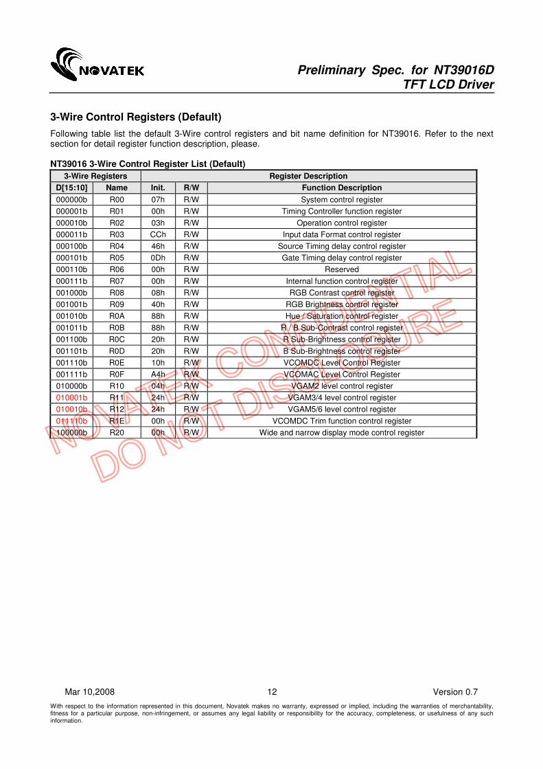
3-Wire Control Registers (Default)
Following table list the default 3-Wire control registers and bit name definition for NT39016. Refer to the next section for detail register function description, please. NT39016 3-Wire Control Register List (Default)
3-Wire Registers Register Description
D[15:10] Name Init. R/W Function Description
000000b R00 07h R/W System control register
000001b R01 00h R/W Timing Controller function register
000010b R02 03h R/W Operation control register
000011b R03 CCh R/W Input data Format control register
000100b R04 46h R/W Source Timing delay control register
000101b R05 0Dh R/W Gate Timing delay control register
000110b R06 00h R/W Reserved
000111b R07 00h R/W Internal function control register
001000b R08 08h R/W RGB Contrast control register
001001b R09 40h R/W RGB Brightness control register
001010b R0A 88h R/W Hue / Saturation control register
001011b R0B 88h R/W R / B Sub-Contrast control register
001100b R0C 20h R/W R Sub-Brightness control register
001101b R0D 20h R/W B Sub-Brightness control register
001110b R0E 10h R/W VCOMDC Level Control Register
001111b R0F A4h R/W VCOMAC Level Control Register
010000b R10 04h R/W VGAM2 level control register
010001b R11 24h R/W VGAM3/4 level control register
010010b R12 24h R/W VGAM5/6 level control register
011110b R1E 00h R/W VCOMDC Trim function control register
100000b R20 00h R/W Wide and narrow display mode control register

Preliminary Spec. for NT39016D TFT LCD Driver
With respect to the information represented in this document, Novatek makes no warranty, expressed or implied, including the warranties of merchantability, fitness for a particular purpose, non-infringement, or assumes any legal liability or responsibility for the accuracy, completeness, or usefulness of any such information.
13 Version 0.7 Mar 10,2008
NT39016 3-Wire Register Bit Definition (Default)
3-Wire Control Register Bit Map
Reg. Bit [7] Bit [6] Bit [5] Bit [4] Bit [3] Bit [2] Bit [1] Bit [0]
R00 PAT3 PAT2 PAT1 PAT0 PWMPDB X STBYB RESETB
R01 X X X SWD2 SWD1 SWD0 DITHB CFTYP
R02 SKIPMOD HDNC1 HDNC0 X FPOL VSET UPDN SHLR
R03 DENPOL CLKPOL HSDPOL VSDPOL SEL3 SEL2 SEL1 SEL0
R04 DDLY7 DDLY6 DDLY5 DDLY4 DDLY3 DDLY2 DDLY1 DDLY0
R05 X HDLY6 HDLY5 HDLY4 HDLY3 HDLY2 HDLY1 HDLY0
R06 X X X X X X X X
R07 FRAD1 FRAD0 INVSL1 INVSL0 PAL PALM - AVGY
R08 X X X CON4 CON3 CON2 CON1 CON0
R09 X BRI6 BRI5 BRI4 BRI3 BRI2 BRI1 BRI0
R0A HUE3 HUE2 HUE1 HUE0 SAT3 SAT2 SAT1 SAT0
R0B SCONB1 SCONB0 SCONR1 SCONR0
R0C X X SBRIR5 SBRIR4 SBRIR3 SBRIR2 SBRIR1 SBRIR0
R0D X X SBRIB5 SBRIB4 SBRIB3 SBRIB2 SBRIB1 SBRIB0
R0E X OTP_BYPS VCDCSL5 VCDCSL4 VCDCSL3 VCDCSL2 VCDCSL1 VCDCSL0
R0F VGLSL1 VGLSL0 VGHSL1 VGHSL0 VCACSL3 VCACSL2 VCACSL1 VCACSL0
R10 X X X GAMEN X V2GAM2 V2GAM1 V2GAM0
R11 X X V4GAM2 V4GAM1 V4GAM0 V3GAM2 V3GAM1 V3GAM0
R12 X X V6GAM2 V6GAM1 V6GAM0 V5GAM2 V5GAM1 V5GAM0
R1E TRMEN7 TRMEN6 TRMEN5 TRMEN4 TRMEN3 TRMEN2 TRMEN1 TRMEN0
R20 X X X X X X WNSEL1 WNSEL0
Note: Register function active at the falling edge of VSD except STBYB, RESETB register bits. Registers require Vsync trigger table
DITHB CFTYP SKIPMOD HDNC FPOL VSET UPDN SHLR DDLY HDLY FRAD INVSL
PAL PALM AVGY CON BRI HUE SAT SCONB SCONR SBRIR SBRIB

Preliminary Spec. for NT39016D TFT LCD Driver
With respect to the information represented in this document, Novatek makes no warranty, expressed or implied, including the warranties of merchantability, fitness for a particular purpose, non-infringement, or assumes any legal liability or responsibility for the accuracy, completeness, or usefulness of any such information.
14 Version 0.7 Mar 10,2008
3-Wire Registers Function Description
R00: System Control Register
Bit Name Initial R/W Description
Bit [7:4] PAT[3:0] 0000b R/W Internal Test Pattern Selection
PAT[3:0] : Select chip embedded test pattern.
Bit [3] PWMPDB 0b (R)
R/W
Internal PWM controller Power Down bit
PWMPDB = “0”, internal PWM controller will be shut down
PWMPDB = “1”, internal PWM controller normal operating
Bit [2] - - - Reserve
Bit [1] STBYB 1b (R)
R/W
Standby Mode function control.
STBYB = “0”, TCON, Source output will turn off and outputs are High-Z.
STBYB = “1”, Normal operation
Bit [0] RESETB 1b R/W
Global Reset Register.
Write “0” to reset whole chip. This bit will set to “1” automatically after chip was reset.
PAT[3:0] : Embedded Auto Test Pattern Selection Register
PAT[3:0] Test Pattern Note
00H Disable Internal Test Pattern Function Default
01H White
02H Black
03H Red
04H Green
05H Blue
06H Yellow
07H Cyan
08H Magenta
09H Gray Level 8
0AH Gray Level 16
0BH Color Bar
0CH Checker Board
0DH Cross Talk Pattern
0EH Horizontal Flick Pattern
0FH Test Pattern Auto Run Mode
Note: WNSEL[1:0] will be disabled under Internal Test Pattern mode.

Preliminary Spec. for NT39016D TFT LCD Driver
With respect to the information represented in this document, Novatek makes no warranty, expressed or implied, including the warranties of merchantability, fitness for a particular purpose, non-infringement, or assumes any legal liability or responsibility for the accuracy, completeness, or usefulness of any such information.
15 Version 0.7 Mar 10,2008
R01: Timing Controller Function Register
Bit Name Initial R/W Description
Bit [4:2] SWD[2:0] 000b R/W Control and switch the relationship between the R,G,B and outputs.
This register is used to match different types of color filters on LCD panel
Bit [1] DITHB 0b R/W
Dithering enable. Active low
DITHB = “0”, Dithering on, (Pseudo 8-bits resolution). (Default mode)
DITHB = “1”, Dithering off, (6-bits resolution, truncation last 2-bits of the input data)
Note 1: Recommend user to enable this function under all modes except for 18 bit RGB input application.
Bit [0] CFTYP 0b R/W
Color Filter Type Select. Select Delta or Stripe mode for data arrangement.
CFTYP = “0”, Stripe mode, Data arrangement keep in the “odd line” state of SWD[2:0] selection.
CFTYP = “1”, Delta mode, Data arrangement controlled by SWD[2:0] setting.
SWD[2:0] function control:
Output (n=0 to 319) Condition SWD2 SWD1 SWD0
3n+1 3n+2 3n+3
R G B Odd Line 0 0 0
G B R Even Line
G B R Odd Line 0 0 1
B R G Even Line
B R G Odd Line 0 1 X
R G B Even Line
G B R Odd Line 1 0 0
R G B Even Line
B R G Odd Line 1 0 1
G B R Even Line
R G B Odd Line 1 1 X
B R G Even Line
SHLR=”1”
UPDN=”1”
Note 1: X = Don’t care Note 2: Data arrangement will keep in the “odd line” state when CFTYP = 0 for stripe mode.
Preliminary Spec. for NT39016D TFT LCD Driver
With respect to the information represented in this document, Novatek makes no warranty, expressed or implied, including the warranties of merchantability, fitness for a particular purpose, non-infringement, or assumes any legal liability or responsibility for the accuracy, completeness, or usefulness of any such information.
16 Version 0.7 Mar 10,2008
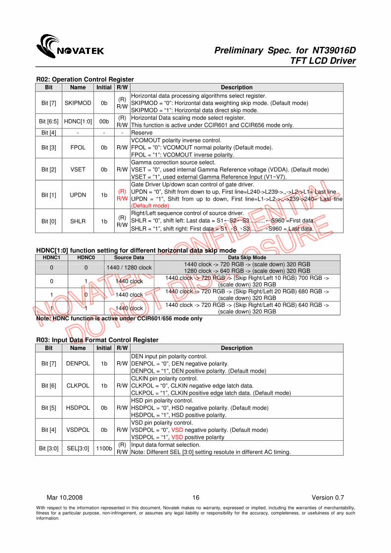
R02: Operation Control Register
Bit Name Initial R/W Description
Bit [7] SKIPMOD 0b (R)
R/W
Horizontal data processing algorithms select register.
SKIPMOD = “0”: Horizontal data weighting skip mode. (Default mode)
SKIPMOD = “1”: Horizontal data direct skip mode.
Bit [6:5] HDNC[1:0] 00b (R)
R/W
Horizontal Data scaling mode select register.
This function is active under CCIR601 and CCIR656 mode only.
Bit [4] - - - Reserve
Bit [3] FPOL 0b R/W
VCOMOUT polarity inverse control.
FPOL = ”0”: VCOMOUT normal polarity (Default mode).
FPOL = ”1”: VCOMOUT inverse polarity.
Bit [2] VSET 0b R/W
Gamma correction source select.
VSET = ”0”, used internal Gamma Reference voltage (VDDA). (Default mode)
VSET = ”1”, used external Gamma Reference Input (V1~V7).
Bit [1] UPDN 1b (R)
R/W
Gate Driver Up/down scan control of gate driver.
UPDN = “0”, Shift from down to up, First line=L240->L239->,,->L2->L1= Last line
UPDN = “1”, Shift from up to down, First line=L1->L2->,,->239->240= Last line (Default mode)
Bit [0] SHLR 1b (R)
R/W
Right/Left sequence control of source driver.
SHLR = “0”, shift left: Last data = S1←S2←S3..........←S960 =First data.
SHLR = “1”, shift right: First data = S1→S→S3........→S960 = Last data.
HDNC[1:0] function setting for different horizontal data skip mode
HDNC1 HDNC0 Source Data Data Skip Mode
0 0 1440 / 1280 clock 1440 clock -> 720 RGB -> (scale down) 320 RGB 1280 clock -> 640 RGB -> (scale down) 320 RGB
0 1 1440 clock 1440 clock -> 720 RGB -> (Skip Right/Left 10 RGB) 700 RGB ->
(scale down) 320 RGB
1 0 1440 clock 1440 clock -> 720 RGB -> (Skip Right/Left 20 RGB) 680 RGB ->
(scale down) 320 RGB
1 1 1440 clock 1440 clock -> 720 RGB -> (Skip Right/Left 40 RGB) 640 RGB ->
(scale down) 320 RGB Note: HDNC function is active under CCIR601/656 mode only
R03: Input Data Format Control Register
Bit Name Initial R/W Description
Bit [7] DENPOL 1b R/W
DEN input pin polarity control.
DENPOL = “0”, DEN negative polarity.
DENPOL = “1”, DEN positive polarity. (Default mode)
Bit [6] CLKPOL 1b R/W
CLKIN pin polarity control.
CLKPOL = “0”, CLKIN negative edge latch data.
CLKPOL = “1”, CLKIN positive edge latch data. (Default mode)
Bit [5] HSDPOL 0b R/W
HSD pin polarity control.
HSDPOL = “0”, HSD negative polarity. (Default mode)
HSDPOL = “1”, HSD positive polarity.
Bit [4] VSDPOL 0b R/W
VSD pin polarity control.
VSDPOL = “0”, VSD negative polarity. (Default mode)
VSDPOL = “1”, VSD positive polarity
Bit [3:0] SEL[3:0] 1100b (R)
R/W
Input data format selection.
Note: Different SEL [3:0] setting resolute in different AC timing.

Preliminary Spec. for NT39016D TFT LCD Driver
With respect to the information represented in this document, Novatek makes no warranty, expressed or implied, including the warranties of merchantability, fitness for a particular purpose, non-infringement, or assumes any legal liability or responsibility for the accuracy, completeness, or usefulness of any such information.
17 Version 0.7 Mar 10,2008
SEL[3:0]: Data input mode SEL3 SEL2 SEL1 SEL0 Data input format Operating frequency
0 0 0 0 CCIR601 YUV 1280 input format (YUV mode A) 24.54 MHz
0 0 0 1 CCIR601 YUV 1280 input format (YUV mode B) 24.54 MHz
0 0 1 0 CCIR601 YUV 1440 input format (YUV mode A) 27 MHz
0 0 1 1 CCIR601 YUV 1440 input format (YUV mode B) 27 MHz
0 1 0 0 CCIR656 YCbCr input format (YcbCr mode A) 27 MHz
0 1 0 1 CCIR656 YCbCr input format (YcbCr mode B) 27 MHz
0 1 1 0 - -
0 1 1 1 - -
1 0 0 0 8-bit digital RGB input format HV Mode (NTSC only) 27 MHz
1 0 0 1 8-bit digital RGB input format DE Mode (NTSC only) 27 MHz
1 0 1 0 8-bit digital RGB through mode input format HV Mode
(NTSC only) 27 MHz
1 0 1 1 8-bit digital RGB through mode input format DE Mode
(NTSC only) 27 MHz
1 1 0 0 24-bit digital RGB input format HV Mode (NTSC only) 6.4 MHz
1 1 0 1 24-bit digital RGB input format DE Mode (NTSC only) 6.4 MHz
1 1 1 0 - -
1 1 1 1 - -
Note::::Hsync and Vsync will be floated in CCIR656 and DE mode
Remark: YUV mode A: Data sequence are “Cb_Y_Cr_Y…”. YUV mode B: Data sequence are “Cr_Y_Cb_Y…”. RGB through mode will bypass 3-wire SWD[2:0] function;TCON will not arrange data color mapping.
R04: Source Timing Delay Control Register
Bit Name Initial R/W Description
Bit [7:0] DDLY[7:0] 46h R/W
Select the HSD signal to 1’st input data delay timing
Under CCIR601 mode, Ths = DDLY[7:0] + 128, (Unit = CLKIN)
Under CCIR656 mode, Ths = DDLY[7:0] + 136, (Unit = CLKIN)
Under RGB 8/24 bit mode, Ths = DDLY[7:0] , (Unit = CLKIN)
The register value will be update to the different default value each time when SEL[3:0] changed. Read the section of “Timing Table” for the detail, please.
Note: DDLY function will be disabled under 8/24bit DE mode and PINCTLB = 0 condition. The default value list in the timing table will be used when PINCTLB = 0.
R05: Gate Timing Delay Control Register
Bit Name Initial R/W Description
Bit [7] - - - Reserve
Bit [6:0] HDLY[6:0] 0Dh R/W
Select the Gate start pulse output delay timing
Tvs = HDLY[6:0], (Unit = HSD)
The register value will be update to the different default value each time when SEL[3:0] changed. Read the section of “Timing Table” for the detail, please.
Note: HDLY function will be disabled under 8/24bit DE mode and PINCTLB = 0 condition. The default value list in the timing table will be used when PINCTLB = 0. R06: Reserved
Bit Name Initial R/W Description
Bit [7:0] - - - Reserve

Preliminary Spec. for NT39016D TFT LCD Driver
With respect to the information represented in this document, Novatek makes no warranty, expressed or implied, including the warranties of merchantability, fitness for a particular purpose, non-infringement, or assumes any legal liability or responsibility for the accuracy, completeness, or usefulness of any such information.
18 Version 0.7 Mar 10,2008
R07: Internal Function Control Register
Bit Name Initial R/W Description
Bit [7:6] FRAD[1:0] 00b R/W Odd frame or Even frame advance control
Bit [5:4] INVSL[1:0] 00b R/W Source Driving Mode Selection Register
Bit [3] PAL 0b (R)
R/W
NTSC or PAL mode selection. Only for 601 and 656 mode.
PAL = “0”, Select NTSC interface mode. (Default mode)
PAL = “1”, Select PAL interface mode.
Bit [2] PALM 0b (R)
R/W
PAL mode input data format selection
PALM = “0”, Select PAL 280 line mode. (Default mode)
PALM = “1”, Select PAL 288 line mode
Bit [1] - - - Reserve
Bit [0] AVGY 0b R/W
Average YUV interface Luminance Y.
AVGY = “0”; Only used odd Y sample for YUV conversion,
AVGY = “1”; Used odd and even Y sample for YUV conversion.
This function active under YUV mode only!
INVSL[1:0]
INVSL1 INVSL0 Driving Mode Notes
0 0 1 - Line Inversion Default
0 1 2 - Line Inversion
1 0 Frame Inversion
1 1 Reserved
FRAD[1:0]
FRAD1 FRAD0 Advance Frame Notes
0 0 Default Odd/Even frame Tstv are the same
0 1 Odd frame Even frame Tstv = HDLY setting +1
1 0 Even frame ODD frame Tstv = HDLY setting +1
1 1 Reserve Reserve
Unit: H
Note: Remark: This function is available under CCIR601 and CCIR656 mode only.
R08: Contrast Control Register
Bit Name Initial R/W Description
Bit [7:5] - - - Reserve
Bit [4:0] CON[4:0] 08h R/W
Display Contrast level adjustment register. (0.125/Step)
Adjust range from 0x00(level = 0) to 0x1F(level = 3.875)
Default value 08h(level = 1.0)
R09: Brightness Control Register
Bit Name Initial R/W Description
Bit [7] - - - Reserve
Bit [6:0] BRI[6:0] 40h R/W
Display Brightness level adjustment register. (2/Step)
Adjust range from 0x00(level = -128) to 0x7F(level = +126)
Default value 0x40(level = +0)
R0A: Hue and Saturation Control Register
Bit Name Initial R/W Description
Bit [7:4] HUE[3:0] 08h R/W
YUV Hue level adjustment register. (5 Deg/Step)
Adjust range from 0x00(level = -40 Deg) to 0x0F(level = +35 Deg)
Default value 0x08(level = 0 Deg)
Cb’ = Cb * cosθ + Cr * sinθ
Cr’ = Cr * cosθ + Cb * sinθ
Bit [3:0] SAT[3:0] 08h R/W
YUV saturation level adjustment register. (0.125/Step)
Adjust range from 0x00(level = 0) to 0x0F(level = 1.875)
Default value 0x08(level = 1.00)
Note: Hue and Saturation function was available under YUV input mode only.
Preliminary Spec. for NT39016D TFT LCD Driver
With respect to the information represented in this document, Novatek makes no warranty, expressed or implied, including the warranties of merchantability, fitness for a particular purpose, non-infringement, or assumes any legal liability or responsibility for the accuracy, completeness, or usefulness of any such information.
19 Version 0.7 Mar 10,2008
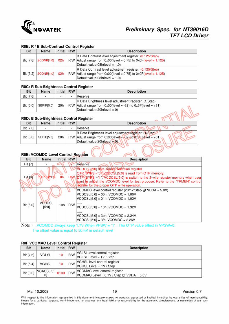
R0B: R / B Sub-Contrast Control Register
Bit Name Initial R/W Description
Bit [7:6] SCONB[1:0] 02h R/W
B Data Contrast level adjustment register. (0.125/Step)
Adjust range from 0x00(level = 0.75) to 0x0F(level = 1.125)
Default value 08h(level = 1.0)
Bit [3:2] SCONR[1:0] 02h R/W
R Data Contrast level adjustment register. (0.125/Step)
Adjust range from 0x00(level = 0.75) to 0x0F(level = 1.125)
Default value 08h(level = 1.0)
R0C: R Sub-Brightness Control Register
Bit Name Initial R/W Description
Bit [7:6] - - - Reserve
Bit [5:0] SBRIR[5:0] 20h R/W
R Data Brightness level adjustment register. (1/Step)
Adjust range from 0x00(level = -32) to 0x3F(level = +31)
Default value 20h(level = 0)
R0D: B Sub-Brightness Control Register
Bit Name Initial R/W Description
Bit [7:6] - - - Reserve
Bit [5:0] SBRIB[5:0] 20h R/W
B Data Brightness level adjustment register. (1/Step)
Adjust range from 0x00(level = -32) to 0x3F(level = +31)
Default value 20h(level = 0)
R0E: VCOMDC Level Control Register
Bit Name Initial R/W Description
Bit [7] - - - Reserve
Bit [6] OTP_BYPS 0h R/W
VCDCSL[5:0] data source selection register
OTP_BYPS =”0”, VCDCSL[5:0] is read from OTP memory.
OTP_BYPS =”1”, VCDCSL[5:0] is switch to the 3-wire register memory when user want to adjust the VCOMDC level for test propose. Refer to the “TRMEN” control register for the proper OTP write operation.
Bit [5:0] VCDCSL
[5:0] 10h R/W
VCOMDC level control register (20mV/Step @ VDDA = 5.0V)
VCDCSL[5:0] = 00h, VCOMDC = 1.00V
VCDCSL[5:0] = 01h, VCOMDC = 1.02V
…..
VCDCSL[5:0] = 10h, VCOMDC = 1.32V
…..
VCDCSL[5:0] = 3eh, VCOMDC = 2.24V
VCDCSL[5:0] = 3fh, VCOMDC = 2.26V
Note: .VCOMDC always keep 1.7V When VPSW = “1” . The OTP value effect in VPSW=0.
The offset value is equal to 50mV in default level R0F VCOMAC Level Control Register
Bit Name Initial R/W Description
Bit [7:6] VGLSL 10 R/W VGLSL level control register
VGLSL Level = 1V / Step
Bit [5:4] VGHSL 10 R/W VGHSL level control register
VGHSL Level = 1V / Step
Bit [3:0] VCACSL[3:
0] 0100 R/W
VCOMAC level control register
VCOMAC Level = 0.1V / Step @ VDDA = 5.0V

Preliminary Spec. for NT39016D TFT LCD Driver
With respect to the information represented in this document, Novatek makes no warranty, expressed or implied, including the warranties of merchantability, fitness for a particular purpose, non-infringement, or assumes any legal liability or responsibility for the accuracy, completeness, or usefulness of any such information.
20 Version 0.7 Mar 10,2008
VCACSL [3:0]
VCSL3 VCSL2 VCSL1 VCSL0 Level (V)
0 0 0 0 4.6 0 0 0 1 4.7
0 0 1 0 4.8
0 0 1 1 4.9
0 1 0 0 5.0 (Default)
0 1 0 1 5.1 0 1 1 0 5.2
0 1 1 1 5.3 1 0 0 0 5.4
1 0 0 1 5.5
1 0 1 0 5.6 1 0 1 1 5.7
1 1 0 0 5.8 1 1 0 1 5.9
1 1 1 0 6.0
1 1 1 1 6.1
Note:When VPSW = “1” .The register can’t be used
The offset value is equal to 100mV in default level
VGHSL[5:4] VGHSL1 VGHSL0 VGH(V)
0 0 12
0 1 13
1 1 14
1 0 15
When VPSW = “1” .The register can’t be used VGLSL[7:6]
VGHSL1 VGHSL0 VGL(V)
0 0 -7
0 1 -8 1 1 -9
1 0 -10
When VPSW = “1” .The register can’t be used R10: VGAM2 Level Control Register
Bit Name Initial R/W Description
Bit [7:5] - - - Reserve
Bit [4] GAMEN 0b R/W
GAMMA adjustment enable control register.(adjustable voltage for V2-V6)
GAEN=”0” or VSET = 1, Gamma correction disabled.
GAEN=”1” & VSET=”0”, Gamma correction enabled
Bit [3] - - - Reserve
Bit [2:0] V2GAM
[2:0] 100b R/W
V2 GAMMA voltage level setting. Function enabled when VSET=”0”
Adjust level = 22mV / Step
R11: VGAM3/4 Level Control Register
Bit Name Initial R/W Description
Bit [7:6] - - - Reserve
Bit [5:3] V4GAM
[2:0] 100b R/W
V4 GAMMA voltage level setting. Function enabled when VSET=”0”
Adjust level = 22mV / Step
Bit [2:0] V3GAM
[2:0] 100b R/W
V3 GAMMA voltage level setting. Function enabled when VSET=”0”
Adjust level = 22mV / Step

Preliminary Spec. for NT39016D TFT LCD Driver
With respect to the information represented in this document, Novatek makes no warranty, expressed or implied, including the warranties of merchantability, fitness for a particular purpose, non-infringement, or assumes any legal liability or responsibility for the accuracy, completeness, or usefulness of any such information.
21 Version 0.7 Mar 10,2008
R12: VGAM5/6 Level Control Register
Bit Name Initial R/W Description
Bit [10:6] - - - Reserve
Bit [5:3] V6GAM
[2:0] 100b R/W
V6 GAMMA voltage level setting. Function enabled when VSET=”0”
Adjust level = 22mV / Step
Bit [2:0] V5GAM
[2:0] 100b R/W
V5 GAMMA voltage level setting. Function enabled when VSET=”0”
Adjust level = 22mV / Step
V2GAM/ V3GAM/ V4GAM/ V5GAM./ V6GAM Level Control Register Setting Table
VxGMA2 VxGMA1 VxGMA0 Voltage level Unit Note
0 0 0 +88 mV
0 0 1 +66 mV
0 1 0 +44 mV
0 1 1 +22 mV
1 0 0 +0(Default) mV
1 0 1 -22 mV
1 1 0 -44 mV
1 1 1 -66 mV
Refer to the Gamma Table for the default voltage level of V2 ~
V6
Note: x = 2, 3, 4, 5, 6
R1E: VCOMDC Trim Function Control Register
Bit Name Initial R/W Description
Bit [7:0] TRMEN
[7:0] 00b R/W
VCOMDC Trim function control register
Write the follow command sequentially to enable the VCOMDC trim function.
Adjust VCDC level:
Set TRMEN[7:0]=00h and write proper VCDCSL[5:0] value using 3-wire cmd.
Programming the VCDCSL value into OTP memory:
Set TRMEN[7:0] as following sequence A0h->5Fh -> EEh -> 00h
OTP_BYPS will be clear to 0b after the programming procedure
Note: The Trim Block can be writing for only “2” times. Trim command exceed the limit may cause the VCOMDC output unknown value.

Preliminary Spec. for NT39016D TFT LCD Driver
With respect to the information represented in this document, Novatek makes no warranty, expressed or implied, including the warranties of merchantability, fitness for a particular purpose, non-infringement, or assumes any legal liability or responsibility for the accuracy, completeness, or usefulness of any such information.
22 Version 0.7 Mar 10,2008
Procedure 1
Set OTP_BYPS = 1
Procedure 2
Update VCDCSL value in
R0E Bit[5:0]
Procedure 3
Set TRMEN[7:0] as following sequence
A0h->5Fh -> EEh -> 00h
Programming the VCDCSL value into OTP memory:
OTP_BYPS will be clear to 0b after
the programming procedure
Procedure 4
Procedure 0
Set VPP_OTP= 7.5V
Procedure 5
Set VPP_OTP= 0V
R20: Wide and narrow display mode Control Register
Bit Name Initial R/W Description
Bit [7:2] - - - Reserve
Bit [1:0] WNSEL
[1:0] 00b R/W Wide and narrow display mode select register
WNSEL[1:0]: Wide and narrow display mode select register
WNSEL1 WNSEL0 Display Mode
0 0 Normal display (Default)
0 1 Narrow display
1 0 Wide display
1 1 234-Line
Note: This function will be enabled under CCIR601 and CCIR656 mode

Preliminary Spec. for NT39016D TFT LCD Driver
With respect to the information represented in this document, Novatek makes no warranty, expressed or implied, including the warranties of merchantability, fitness for a particular purpose, non-infringement, or assumes any legal liability or responsibility for the accuracy, completeness, or usefulness of any such information.
23 Version 0.7 Mar 10,2008
Function Description
Power On/Off Sequence
To prevent IC from power on reset fail, the rising time (TPOR) of digital power supply VDD, should be control within the specification. Refer to the “AC Characteristic” for the detail timing, please. Power-On Timing Sequence:
Power-off Timing Sequence:
External Reset (RSTB)
To prevent from abnormal reset condition, a glitch filter for RSTB is embedded in this chip. The external reset signal should keep active for large then reset time (TRSTB). Refer to the AC/DC Specification for the requirement.

Preliminary Spec. for NT39016D TFT LCD Driver
With respect to the information represented in this document, Novatek makes no warranty, expressed or implied, including the warranties of merchantability, fitness for a particular purpose, non-infringement, or assumes any legal liability or responsibility for the accuracy, completeness, or usefulness of any such information.
24 Version 0.7 Mar 10,2008
Input Data VS Output Voltage
Source Driver data output sequence can be control by “SHLR”. Output SO1 SO2 SO3 - - - SO958 SO959 SO960
SHLR=”1” First data ���� Last data
SHLR=”0” Last data First data
Gate Driver scan output sequence can be control by “UPDN”.
Scan GO1 GO2 GO3 - - - GO238 GO239 GO240
UPDN=”1” First scan ���� Last scan
UPDN=”0” Last scan First scan
The figure below shows the relationship between the input data and the output voltage. Refer to the following pages to get the relative resistor value and voltage calculation method, please. Postive (VCOM = L)
0.0000.5001.0001.5002.0002.5003.0003.5004.0004.5005.000
00H 03H 06H 09H 0CH 0FH 12H 15H 18H 1BH 1EH 21H 24H 27H 2AH 2DH 30H 33H 36H 39H 3CH 3FHINPUTVout(V)
Negative (VCOM = H)
0.0000.5001.0001.5002.0002.5003.0003.5004.0004.5005.000
00H 04H 08H 0CH 10H 14H 18H 1CH 20H 24H 28H 2CH 30H 34H 38H 3CHINPUTVout(V)
Preliminary Spec. for NT39016D TFT LCD Driver
With respect to the information represented in this document, Novatek makes no warranty, expressed or implied, including the warranties of merchantability, fitness for a particular purpose, non-infringement, or assumes any legal liability or responsibility for the accuracy, completeness, or usefulness of any such information.
25 Version 0.7 Mar 10,2008
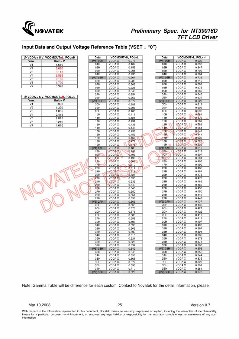
Input Data and Output Voltage Reference Table (VSET = “0”)
@ VDDA = 5 V, VCOMOUT=L, POL=H
Vno. Unit = V
V1 4.610
V2 3.680
V3 3.115
V4 2.585
V5 2.185
V6 1.790
V7 0.390
@ VDDA = 5 V, VCOMOUT=H, POL=L
Vno. Unit = V
V1 0.390
V2 1.320 V3 1.885
V4 2.415
V5 2.815
V6 3.210
V7 4.610
Data VCOMOUT=H, POL=L
(V1) 00H VDDA X 0.078
01H VDDA X 0.107
02H VDDA X 0.153
03H VDDA X 0.201
04H VDDA X 0.236
(V2) 05H VDDA X 0.264
06H VDDA X 0.288
07H VDDA X 0.308
08H VDDA X 0.325
09H VDDA X 0.340
0AH VDDA X 0.354
0BH VDDA X 0.366
(V3) 0CH VDDA X 0.377
0DH VDDA X 0.388
0EH VDDA X 0.398
0FH VDDA X 0.408
10H VDDA X 0.416
11H VDDA X 0.424
12H VDDA X 0.431
13H VDDA X 0.438
14H VDDA X 0.446
15H VDDA X 0.453
16H VDDA X 0.459
17H VDDA X 0.465
18H VDDA X 0.472
19H VDDA X 0.478
(V4) 1AH VDDA X 0.483
1BH VDDA X 0.488
1CH VDDA X 0.493
1DH VDDA X 0.499
1EH VDDA X 0.505
1FH VDDA X 0.510
20H VDDA X 0.514
21H VDDA X 0.519
22H VDDA X 0.525
23H VDDA X 0.530
24H VDDA X 0.535
25H VDDA X 0.540
26H VDDA X 0.545
27H VDDA X 0.550
28H VDDA X 0.554
29H VDDA X 0.558
(V5) 2AH VDDA X 0.563
2BH VDDA X 0.568
2CH VDDA X 0.573
2DH VDDA X 0.578
2EH VDDA X 0.583
2FH VDDA X 0.588
30H VDDA X 0.593
31H VDDA X 0.598
32H VDDA X 0.603
33H VDDA X 0.609
34H VDDA X 0.615
35H VDDA X 0.621
36H VDDA X 0.626
37H VDDA X 0.632
(V6) 38H VDDA X 0.642
39H VDDA X 0.648
3AH VDDA X 0.656
3BH VDDA X 0.665
3CH VDDA X 0.677
3DH VDDA X 0.693
3EH VDDA X 0.719
(V7) 3FH VDDA X 0.922
Data VCOMOUT=L, POL=H
(V1) 00H VDDA X 0.922
01H VDDA X 0.893
02H VDDA X 0.847
03H VDDA X 0.799
04H VDDA X 0.764
(V2) 05H VDDA X 0.736
06H VDDA X 0.712
07H VDDA X 0.692
08H VDDA X 0.675
09H VDDA X 0.660
0AH VDDA X 0.646
0BH VDDA X 0.634
(V3) 0CH VDDA X 0.623
0DH VDDA X 0.612
0EH VDDA X 0.602
0FH VDDA X 0.592
10H VDDA X 0.584
11H VDDA X 0.576
12H VDDA X 0.569
13H VDDA X 0.562
14H VDDA X 0.554
15H VDDA X 0.547
16H VDDA X 0.541
17H VDDA X 0.535
18H VDDA X 0.528
19H VDDA X 0.522
(V4) 1AH VDDA X 0.517
1BH VDDA X 0.512
1CH VDDA X 0.507
1DH VDDA X 0.501
1EH VDDA X 0.495
1FH VDDA X 0.490
20H VDDA X 0.486
21H VDDA X 0.481
22H VDDA X 0.475
23H VDDA X 0.470
24H VDDA X 0.465
25H VDDA X 0.460
26H VDDA X 0.455
27H VDDA X 0.450
28H VDDA X 0.446
29H VDDA X 0.442
(V5) 2AH VDDA X 0.437
2BH VDDA X 0.432
2CH VDDA X 0.427
2DH VDDA X 0.422
2EH VDDA X 0.417
2FH VDDA X 0.412
30H VDDA X 0.407
31H VDDA X 0.402
32H VDDA X 0.397
33H VDDA X 0.391
34H VDDA X 0.385
35H VDDA X 0.379
36H VDDA X 0.374
37H VDDA X 0.368
(V6) 38H VDDA X 0.358
39H VDDA X 0.352
3AH VDDA X 0.344
3BH VDDA X 0.335
3CH VDDA X 0.323
3DH VDDA X 0.307
3EH VDDA X 0.281
(V7) 3FH VDDA X 0.078
Note: Gamma Table will be difference for each custom. Contact to Novatek for the detail information, please.
Preliminary Spec. for NT39016D TFT LCD Driver
With respect to the information represented in this document, Novatek makes no warranty, expressed or implied, including the warranties of merchantability, fitness for a particular purpose, non-infringement, or assumes any legal liability or responsibility for the accuracy, completeness, or usefulness of any such information.
26 Version 0.7 Mar 10,2008
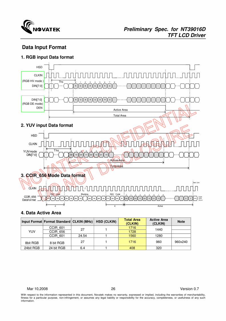
Data Input Format
1. RGB input Data format
- - - - - - - -
Active Area
Total Area
0 2 3 4 65 7
- - - - - - - -
HSD
CLKIN
(RGB HV mode )
(RGB DE mode)
-
8
-
1
R BG R BG R G
DEN
DIN[7:0]
DIN[7:0]
Ths
R BG R BG R G
2. YUV input Data format
Cb0 Cr0 Y1 Cb1 Y2 Cr1 Y3 - - - - - - - -
Active Area
Total Area
0 2 3 4 65 7
HSD
CLKIN
YUV mode-
8
Y0
1
DIN[7:0]
Ths
3. CCIR_656 Mode Data format
FFh 00h 00h XY Cb0 Cr0 Y1 Cb1 Y2 Cr1 Y3 - - Cr Y
0 2 3 4 65 7
CLKIN
CCIR_656Data format
-
8
Y0
1
10h 80h 10h80h10h 80h 10h80h
////FFh 00h 00h XY
//// //FFh
4 4
Next Line
Digital
Video
Stream
Active
EAV code Blanking SAV Code
4. Data Active Area
Input Format Format Standard CLKIN (MHz) HSD (CLKIN) Total Area
(CLKIN) Active Area
(CLKIN) Note
CCIR_601 1716
CCIR_656 27 1
1728 1440
YUV
CCIR_601 24.54 1 1560 1280
8bit RGB 8 bit RGB 27 1 1716 960 960x240
24bit RGB 24 bit RGB 6.4 1 408 320

Preliminary Spec. for NT39016D TFT LCD Driver
With respect to the information represented in this document, Novatek makes no warranty, expressed or implied, including the warranties of merchantability, fitness for a particular purpose, non-infringement, or assumes any legal liability or responsibility for the accuracy, completeness, or usefulness of any such information.
27 Version 0.7 Mar 10,2008
5. YUV_601/656 to RGB conversion
AVGY=0: Rn = 1.164(Y2n-16) +1.596(Crn -128) Gn = 1.164(Y2n-16) -0.813(Crn -128) -0.392(Cbn -128); [Y=16~235,Cr & Cb=16~240] Bn = 1.164(Y2n-16) +2.017(Cbn-128) AVGY=1: Rn = 1.164((Y2n +Y2n+1)/2 -16)+1.596(Crn-128) Gn = 1.164((Y2n +Y2n+1)/2 -16)-0.813(Crn-128)-0.392(Cbn-128) ; [Y=16~235,Cr & Cb=16~240] Bn = 1.164((Y2n +Y2n+1)/2 -16)+2.017(Cbn-128)
6. Brightness / Contrast Adjustment
Contrast: Gn = G[7:0] x Contrast( 0 to 3.875) Rn = R[7:0] x Contrast( 0 to 3.875) x Sub-Contrast R( 0.8 to 1.175) Bn = B[7:0] x Contrast( 0 to 3.875) x Sub-Contrast B( 0.8 to 1.175) Brightness: Gn = G[7:0] + Brightness( -128 to +126) Rn = R[7:0] + Brightness ( -128 to +126) + Sub-Brightness R( -32 to +31) Bn = B[7:0] + Brightness ( -128 to +126) + Sub-Brightness B( -32 to +31)

Preliminary Spec. for NT39016D TFT LCD Driver
With respect to the information represented in this document, Novatek makes no warranty, expressed or implied, including the warranties of merchantability, fitness for a particular purpose, non-infringement, or assumes any legal liability or responsibility for the accuracy, completeness, or usefulness of any such information.
28 Version 0.7 Mar 10,2008
Absolute Maximum Ratings
Logic supply voltage, VDD -0.5V to +5V Analog supply voltage, VDDA -0.5V to +7.5V Supply voltage, VDDP -0.5V to +5.5V Supply voltage, V1~ V6 -0.3 ~VDDA+0.3 VGH~VGL -0.3~ +25V
Storage temperature -55℃℃℃℃ to +125℃℃℃℃
Operating temperature -20℃℃℃℃ to +85℃℃℃℃
Stresses above those listed under “Absolute Maximum Ratings” may cause permanent damage to the device. These are stress ratings only. Functional operation of this device at these or under any other conditions above those indicated in the operational sections of this specification are not implied and exposure to absolute maximum rating conditions for extended periods may affect device reliability.
DC Electrical Characteristics
(For the digital circuit: Test Condition: VDD=VDDP=3.3V , VDDA=5.0V, GND=GNDA=GNDP= 0V, TA=25℃℃℃℃)
Parameter Symbol Min. Typ. Max. Unit Conditions
Digital Block Circuit
Digital Supply Voltage VDD 3.0 3.3 3.6 V Digital power
Low Level Input Voltage Vil GND - 0.2xVDD V Digital input pins TA=85℃℃℃℃
High Level Input Voltage Vih 0.8xVDD - VDD V Digital input pins TA=85℃℃℃℃
Low Level Input Voltage Vil GND - 0.2xVDD V Digital input pins TA=25℃℃℃℃
High Level Input Voltage Vih 0.8xVDD - VDD V Digital input pins TA=25℃℃℃℃
Low Level Input Voltage Vil GND - 0.1xVDD V Digital input pins TA= -20℃℃℃℃
High Level Input Voltage Vih 0.9xVDD - VDD V Digital input pins TA= -20℃℃℃℃
Input Leakage Current Ii - - ±1 µA Digital input pins
Pull-high/low Impedance Rin - 200K - ohm Digital control input pins
High Level Output Voltage Voh VDD-0.4 - VDD V Digital output pins; Ioh = 400 uA
Low Level Output Voltage Vol GND - GND+0.4 V Digital output pins; Iol = -400 uA
Digital Stand-by Current Iddst - (50) (100) uA No load, CLKIN/VSD/HSD stopped
Digital Operating Current Idd1 - 2 - mA CLKIN = 27 MHz (CCIR601mode)
Power Circuit
Charge Pump Supply Voltage
VDDP 3.0 3.3 3.6 V For VGH/VGL power and
Source Driver power, must in this range
VCOMAC output level VCOMAC 4.6 - 6.1 V By VCSL[2:0] setting
VCOMAC = V(VCSL[2:0]) +- 100mV
VCOMDC output level VCOMDC 1.0 - 2.26 V By VCDCSL[5:0] setting
VCOMDC = V(VCDCSL[5:0]) +- 50mV
Positive power supply VGH 14.5 15 15.5 V Gate driver load + procard load
Negative power supply VGL -9 -10 -11 V Gate driver load + procard load
Base drive current IDRV - - 10 mA VDDP=3.3V, DRV=0.7 V
DRV output voltage VDRV GND
+0.1
- VDD
-0.1
V
Feed back voltage VFB 0.55 0.6 0.65 V DC/DC operating, VBL current=20 mA

Preliminary Spec. for NT39016D TFT LCD Driver
With respect to the information represented in this document, Novatek makes no warranty, expressed or implied, including the warranties of merchantability, fitness for a particular purpose, non-infringement, or assumes any legal liability or responsibility for the accuracy, completeness, or usefulness of any such information.
29 Version 0.7 Mar 10,2008
Parameter Symbol Min. Typ. Max. Unit Conditions
Analog Block Circuit
Analog Supply Voltage VDDA 5.0 5.2 6.0 V Analog circuit power from Power Block
- ±20 ±35 mV Vo=0.1V ~ 0.5V &
VDDA - 0.5 ~ VDDA - 0.1V Voltage Deviation of Outputs Vvd
±15 ±25 mV Vo=0.5V ~ VDDA-0.5V
Low-Level Output Current of VCOMOUT
IOLF - -10 - mA Force VCOMAC = 6.0V
VCOMOUT output = 0V V.S. 0.9V
High-Level Output Current of VCOMOUT
IOHF - 10 - mA Force VCOMAC = 6.0V
VCOMOUT output = 6.0V V.S 5.1V
Source Low-Level Output Current
IOLS - -30 - uA Son = Vo V.S. (Vo+0.9)
Source High-Level Output Current
IOHS - 30 - uA Son = Vo V.S. (Vo-0.9)
Gate Low-Level Output Current
IOLG - -250 - µA GOn; Vo=VGL V.S. (VGL +0.5)
Gate High-Level Output Current
IOHG - 250 - µA GOn; Vo=VGH V.S. (VGH -0.5)
Analog Stand-by Current Iddast - - 100 µA STBYB = ”0”, all function are shutdown
Analog Operating Current Idda - 10 - mA No load, CLKIN = 27MHz, Fld=15KHz

Preliminary Spec. for NT39016D TFT LCD Driver
With respect to the information represented in this document, Novatek makes no warranty, expressed or implied, including the warranties of merchantability, fitness for a particular purpose, non-infringement, or assumes any legal liability or responsibility for the accuracy, completeness, or usefulness of any such information.
30 Version 0.7 Mar 10,2008
AC Electrical Characteristics
Test Condition: (VDD=VDDP=3.3V, VDDA=5.0V, GND=GNDA=GNDP=0V, TA= 25℃℃℃℃)
Parameter Symbol Min. Typ. Max. Unit Conditions
System Operation Timing
VDD power source slew time
TPOR 1000 us From 0V to 90% VDD
RSTB active pulse width TRSTB 40 us VDD = 3.3V
Input Output Timing
CLKIN clock time Tclk - 35.7 ns CLKIN = 28MHz
HSD to CLKIN Thc - - 1 CLKIN
HSD width Thwh 1 - - CLKIN
VSD width Tvwh 1 - - Th
HSD period time Th 60 63.56 67 us
VSD setup time Tvst 12 - - ns
VSD hold time Tvhd 12 - - ns
HSD setup time Thst 12 - - ns
HSD hold time Thhd 12 - - ns
Data set-up time Tdsu 12 - - ns DIN[23:0] to CLKIN
Data hold time Tdhd 12 - - ns DIN[23:0] to CLKIN
DEN setup time Tesd 12 - ns DEN to CLKIN
Time that VSD to 1st line
data input Tvs 2 13 127 Th
@CCIR601 / 8bit RGB HV mode
Control by HDLY[6:0] setting
Tvs = HDLY[6:0]
Time that CCIR_V to 1st line
data input Tvs 12 20 28 Th
@CCIR656 NTSC mode
Control by HDLY[6:0] setting
Tvs = HDLY[6:0]
Time that CCIR_V to 1st line
data input Tvs 17 25 33 Th
@CCIR656 PAL mode
Control by HDLY[6:0] setting
Tvs = HDLY[6:0]
Time that VSD to 1st line
data input Tvs 2 13 127 Th
@24bit RGB HV mode
Control by HDLY[6:0] setting
Tvs = HDLY[6:0]
Source output stable time 1 Tst - 25 30 us 96% final, CL=30pF, RL=2K
Gate output stable time Tgst - 500 1000 ns 96% final, CL=40pF
VCOMOUT output stable time
Tcst - 4 8 us 96% final, CL=33nF, RL=100ohm
3-wire serial communication AC timing
Serial clock Tspck 320 - - ns
SPCK pulse duty Tscdut 40 50 60 %
Serial data setup time Tisu 120 - - ns
Serial data hold time Tihd 120 - - ns
Serial clock high/low Tssw 120 - - ns
Chip select distinguish Tcd 1 - - us
SPENA to VSD Tcv 1 - - us

Preliminary Spec. for NT39016D TFT LCD Driver
With respect to the information represented in this document, Novatek makes no warranty, expressed or implied, including the warranties of merchantability, fitness for a particular purpose, non-infringement, or assumes any legal liability or responsibility for the accuracy, completeness, or usefulness of any such information.
31 Version 0.7 Mar 10,2008
Timing Table
CCIR601 Mode A/B *
Parameter Symbol Min. Typ. Max. Unit Conditions
CLKIN frequency Fclk - 24.54 /27
MHz VDD = 3.0 ~3.6V
CLKIN cycle time Tclk - 40/37 ns
CLKIN pulse duty Tcwh 40 50 60 % Tclk
Time from HSD to VCOMOUT Thvcm - 66 - CLKIN
Time from HSD to DATSEQ Thseq - 60 - CLKIN
Time from HSD to Gate output n line Thgz 30 - CLKIN
Time from HSD to Gate output n+1 line Thgo 100 - CLKIN
Time from HSD to 1’st data input (PAL) Ths 128 264 - CLKIN DDLY = 136, Offset = 128 (fixed)
Time from HSD to 1’st data input (NTSC) Ths 128 244 - CLKIN DDLY = 116, Offset = 128 (fixed)
CCIR656 Mode A/B *
Parameter Symbol Min. Typ. Max. Unit Conditions
CLKIN frequency Fclk - 27 MHz VDD = 3.0 ~3.6V
CLKIN cycle time Tclk - 37 ns
CLKIN pulse duty Tcwh 40 50 60 % Tclk
Time from EAV to VCOMOUT Thvcm - 66 - CLKIN
Time from EAV to DATSEQ Thseq - 60 - CLKIN
Time from HSD to Gate output n line Thgz 30 - CLKIN
Time from HSD to Gate output n+1 line Thgo 100 - CLKIN
Time from EAV to 1’st data input (PAL) Ths 128 288 CLKIN DDLY = 152, Offset = 128 (fixed)
Time from EAV to 1’st data input (NTSC) Ths 128 276 CLKIN DDLY = 140, Offset = 128 (fixed)
8 Bit RGB 960 CH Mode
Parameter Symbol Min. Typ. Max. Unit Conditions
CLKIN frequency Fclk - 27 MHz VDD = 3.0 ~3.6V
CLKIN cycle time Tclk - 37 ns
CLKIN pulse duty Tcwh 40 50 60 % Tclk
Time from HSD to VCOMOUT Thvcm - 25 - CLKIN
Time from HSD to DATSEQ Thseq - 20 - CLKIN
Time from HSD to Gate output n line Thgz 5 - CLKIN
Time from HSD to Gate output n+1 line Thgo 45 - CLKIN
Time that HSD to 1’st data input(NTSC) Ths 35 70 255 CLKIN DDLY = 70, Offset = 0 (fixed)
24 Bit RGB Mode (@ SEL[3:0] = 1100 or 1101)
Parameter Symbol Min. Typ. Max. Unit Conditions
CLKIN frequency Fclk - 6.4 MHz VDD = 3.0 ~3.6V
CLKIN cycle time Tclk - 156 ns
CLKIN pulse duty Tcwh 40 50 60 % Tclk
Time from HSD to VCOMOUT Thvcm - 30 - CLKIN
Time from HSD to DATSEQ Thseq - 20 - CLKIN
Time from HSD to Gate output n line Thgz 5 - CLKIN
Time from HSD to Gate output n+1 line Thgo 45 - CLKIN
Time that HSD to 1’st data input(NTSC) Ths 40 70 255 CLKIN DDLY =70, Offset = 0 (fixed)

Preliminary Spec. for NT39016D TFT LCD Driver
With respect to the information represented in this document, Novatek makes no warranty, expressed or implied, including the warranties of merchantability, fitness for a particular purpose, non-infringement, or assumes any legal liability or responsibility for the accuracy, completeness, or usefulness of any such information.
32 Version 0.7 Mar 10,2008
Timing Diagram
Clock and Data Input Timing Diagram
Tvst Tvhd
Thst
Thhd
Th
Thc
Last
CLKIN
VSD
HSD
HSD
DIN[7:0]
CLKIN
//
//
//
Last-1 data Last data
//
//
//
//
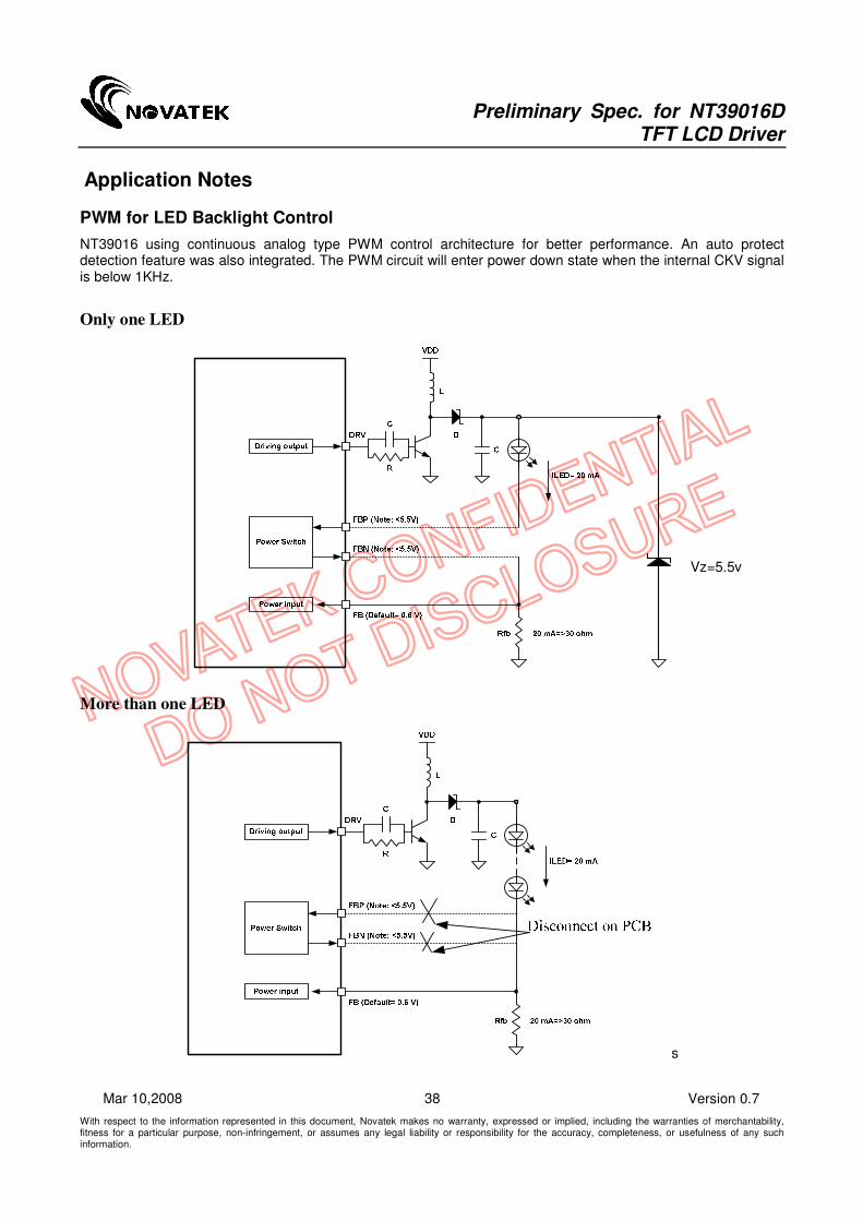
DIN[7:0] 2nd data
//
//
Last data
Tdsu
First data
Tdhd
Tclk
TcwlTcwh
LastCLKIN//
First
Thwh
//Tesu
DEN
3-Wire Timing Diagram
D15
Tisu
Tihd
SPDA
SPCK
SPENB
Tspck
Tckh Tckl
Tcd
VSD
D14 D13 D2 D1 D0 D15 D14
////// D1 D0 ////Tcv//Teck Tcke

Preliminary Spec. for NT39016D TFT LCD Driver
With respect to the information represented in this document, Novatek makes no warranty, expressed or implied, including the warranties of merchantability, fitness for a particular purpose, non-infringement, or assumes any legal liability or responsibility for the accuracy, completeness, or usefulness of any such information.
33 Version 0.7 Mar 10,2008
Source Driver Output Timing Diagram
Gate Driver Output Timing Diagram
VCOMOUT(Odd frame,FPOL="L")
(Even frame,FPOL="L")
(Odd frame,FPOL="H")
(Even frame,FPOL="H")
240G240 or G1
G1 or G240 1
2G2 or G239
VSD
HSD 1 2
239G239 or G2
Tstv
VCOMOUT
VCOMOUT
VCOMOUT
Preliminary Spec. for NT39016D TFT LCD Driver
With respect to the information represented in this document, Novatek makes no warranty, expressed or implied, including the warranties of merchantability, fitness for a particular purpose, non-infringement, or assumes any legal liability or responsibility for the accuracy, completeness, or usefulness of any such information.
34 Version 0.7 Mar 10,2008
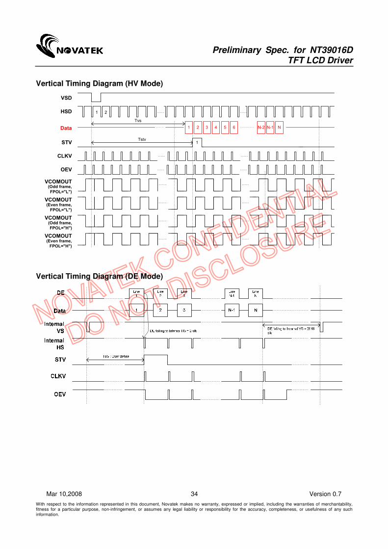
Vertical Timing Diagram (HV Mode)
VCOMOUT(Odd frame,
FPOL="L")
(Even frame,
FPOL="L")
(Odd frame,
FPOL="H")
(Even frame,
FPOL="H")
STV 1
CLKV
VSD
HSD 1 2
Tstv
VCOMOUT
VCOMOUT
VCOMOUT
OEV
Data NN-11 2 3 4 5 N-26
Tvs
Vertical Timing Diagram (DE Mode)

Preliminary Spec. for NT39016D TFT LCD Driver
With respect to the information represented in this document, Novatek makes no warranty, expressed or implied, including the warranties of merchantability, fitness for a particular purpose, non-infringement, or assumes any legal liability or responsibility for the accuracy, completeness, or usefulness of any such information.
35 Version 0.7 Mar 10,2008
Input Data Timing (24 bit RGB mode for 960 x 240 @ SEL[3:0] = 1100b)
R R R R R R R R
Active Area = 320 (RGB)
Total Area = 408 CLKIN
B B B B B B B B
HSD
CLKIN(6.4 MHz)
R
BB BB B BB B B
DEN(DE Mode)
DIN[7:0]
DIN[23:16]
Default = 70
R RR R RR R R
G G G G G G G GGG GG G GG G GDIN[15:8]
Valid Line
VSD
HSD 1 2
Default = 13 lines
13 14
Display lines = 240 lines
253 254 1 2
1 2 70 71
Total lines = 263 lines

Preliminary Spec. for NT39016D TFT LCD Driver
With respect to the information represented in this document, Novatek makes no warranty, expressed or implied, including the warranties of merchantability, fitness for a particular purpose, non-infringement, or assumes any legal liability or responsibility for the accuracy, completeness, or usefulness of any such information.
36 Version 0.7 Mar 10,2008
Pad Location

Preliminary Spec. for NT39016D TFT LCD Driver
With respect to the information represented in this document, Novatek makes no warranty, expressed or implied, including the warranties of merchantability, fitness for a particular purpose, non-infringement, or assumes any legal liability or responsibility for the accuracy, completeness, or usefulness of any such information.
37 Version 0.7 Mar 10,2008
Alignment Mark
Pad Information
Symbol Dimension (um)
B 17
B3 110
C 100
C1 127
C2 27
C4 115
D2 30
E1 21310
E2 760
E4 65
E5 65
*Remark: Chip dimension include scribe line
Preliminary Spec. for NT39016D TFT LCD Driver
With respect to the information represented in this document, Novatek makes no warranty, expressed or implied, including the warranties of merchantability, fitness for a particular purpose, non-infringement, or assumes any legal liability or responsibility for the accuracy, completeness, or usefulness of any such information.
38 Version 0.7 Mar 10,2008
Application Notes
PWM for LED Backlight Control
NT39016 using continuous analog type PWM control architecture for better performance. An auto protect detection feature was also integrated. The PWM circuit will enter power down state when the internal CKV signal is below 1KHz.
Only one LED
More than one LED
s
Vz=5.5v

Preliminary Spec. for NT39016D TFT LCD Driver
With respect to the information represented in this document, Novatek makes no warranty, expressed or implied, including the warranties of merchantability, fitness for a particular purpose, non-infringement, or assumes any legal liability or responsibility for the accuracy, completeness, or usefulness of any such information.
39 Version 0.7 Mar 10,2008
Appendix A: Pad Coordinate
Pad No. Name X Y Pad No. Name X Y Pad No. Name X Y Pad No. Name X Y Pad No. Name X Y
1 Alignment -10532.5 -257.5 89 TP7 635 -257.5 177 GO018 10411.5 120 265 GO194 8915.5 120 353 SO060 7307.5 120
2 DUM -10412 -257.5 90 TP6 762 -257.5 178 GO020 10394.5 260 266 GO196 8898.5 260 354 SO061 7290.5 260
3 C4M -10287 -257.5 91 TP5 889 -257.5 179 GO022 10377.5 120 267 GO198 8881.5 120 355 SO062 7273.5 120
4 C4M -10160 -257.5 92 DUM 1016 -257.5 180 GO024 10360.5 260 268 GO200 8864.5 260 356 SO063 7256.5 260
5 C4P -10033 -257.5 93 TP4 1143 -257.5 181 GO026 10343.5 120 269 GO202 8847.5 120 357 SO064 7239.5 120
6 C4P -9906 -257.5 94 TP3 1270 -257.5 182 GO028 10326.5 260 270 GO204 8830.5 260 358 SO065 7222.5 260
7 VGH -9779 -257.5 95 DUM 1397 -257.5 183 GO030 10309.5 120 271 GO206 8813.5 120 359 SO066 7205.5 120
8 VGH -9652 -257.5 96 TP2 1524 -257.5 184 GO032 10292.5 260 272 GO208 8796.5 260 360 SO067 7188.5 260
9 VGH -9525 -257.5 97 TP1 1651 -257.5 185 GO034 10275.5 120 273 GO210 8779.5 120 361 SO068 7171.5 120
10 C3M -9398 -257.5 98 DUM 1778 -257.5 186 GO036 10258.5 260 274 GO212 8762.5 260 362 SO069 7154.5 260
11 C3M -9271 -257.5 99 TP0 1905 -257.5 187 GO038 10241.5 120 275 GO214 8745.5 120 363 SO070 7137.5 120
12 C3P -9144 -257.5 100 VDDA 2032 -257.5 188 GO040 10224.5 260 276 GO216 8728.5 260 364 SO071 7120.5 260
13 C3P -9017 -257.5 101 VDDA 2159 -257.5 189 GO042 10207.5 120 277 GO218 8711.5 120 365 SO072 7103.5 120
14 C2P -8890 -257.5 102 VDDA 2286 -257.5 190 GO044 10190.5 260 278 GO220 8694.5 260 366 SO073 7086.5 260
15 C2P -8763 -257.5 103 GNDA 2413 -257.5 191 GO046 10173.5 120 279 GO222 8677.5 120 367 SO074 7069.5 120
16 C2M -8636 -257.5 104 GNDA 2540 -257.5 192 GO048 10156.5 260 280 GO224 8660.5 260 368 SO075 7052.5 260
17 C2M -8509 -257.5 105 GNDA 2667 -257.5 193 GO050 10139.5 120 281 GO226 8643.5 120 369 SO076 7035.5 120
18 COM1_L -8382 -257.5 106 GND 2794 -257.5 194 GO052 10122.5 260 282 GO228 8626.5 260 370 SO077 7018.5 260
19 COM1_L -8255 -257.5 107 GND 2921 -257.5 195 GO054 10105.5 120 283 GO230 8609.5 120 371 SO078 7001.5 120
20 DUM -8128 -257.5 108 GND 3048 -257.5 196 GO056 10088.5 260 284 GO232 8592.5 260 372 SO079 6984.5 260
21 C1AP -8001 -257.5 109 VDD 3175 -257.5 197 GO058 10071.5 120 285 GO234 8575.5 120 373 SO080 6967.5 120
22 C1AP -7874 -257.5 110 VDD 3302 -257.5 198 GO060 10054.5 260 286 GO236 8558.5 260 374 SO081 6950.5 260
23 C1AM -7747 -257.5 111 VDD 3429 -257.5 199 GO062 10037.5 120 287 GO238 8541.5 120 375 SO082 6933.5 120
24 C1AM -7620 -257.5 112 RSTB 3556 -257.5 200 GO064 10020.5 260 288 GO240 8524.5 260 376 SO083 6916.5 260
25 C1M -7493 -257.5 113 DUM 3683 -257.5 201 GO066 10003.5 120 289 COM2_R 8485.5 260 377 SO084 6899.5 120
26 C1M -7366 -257.5 114 SPDA 3810 -257.5 202 GO068 9986.5 260 290 COM2_R 8451.5 260 378 SO085 6882.5 260
27 C1P -7239 -257.5 115 SPSW 3937 -257.5 203 GO070 9969.5 120 291 COM2_R 8417.5 260 379 SO086 6865.5 120
28 C1P -7112 -257.5 116 PINCTLB 4064 -257.5 204 GO072 9952.5 260 292 COM2_R 8383.5 260 380 SO087 6848.5 260
29 GNDP -6985 -257.5 117 SPCK 4191 -257.5 205 GO074 9935.5 120 293 COM2_R 8349.5 260 381 SO088 6831.5 120
30 GNDP -6858 -257.5 118 SPENB 4318 -257.5 206 GO076 9918.5 260 294 SO001 8310.5 260 382 SO089 6814.5 260
31 GNDP -6731 -257.5 119 DEN 4445 -257.5 207 GO078 9901.5 120 295 SO002 8293.5 120 383 SO090 6797.5 120
32 VDDP -6604 -257.5 120 HSD 4572 -257.5 208 GO080 9884.5 260 296 SO003 8276.5 260 384 SO091 6780.5 260
33 VDDP -6477 -257.5 121 VSD 4699 -257.5 209 GO082 9867.5 120 297 SO004 8259.5 120 385 SO092 6763.5 120
34 VDDP -6350 -257.5 122 CLKIN 4826 -257.5 210 GO084 9850.5 260 298 SO005 8242.5 260 386 SO093 6746.5 260
35 DUM -6223 -257.5 123 DIN23 4953 -257.5 211 GO086 9833.5 120 299 SO006 8225.5 120 387 SO094 6729.5 120
36 VGL -6096 -257.5 124 DIN22 5080 -257.5 212 GO088 9816.5 260 300 SO007 8208.5 260 388 SO095 6712.5 260
37 VGL -5969 -257.5 125 DIN21 5207 -257.5 213 GO090 9799.5 120 301 SO008 8191.5 120 389 SO096 6695.5 120
38 VGL -5842 -257.5 126 DIN20 5334 -257.5 214 GO092 9782.5 260 302 SO009 8174.5 260 390 SO097 6678.5 260
39 DUM -5715 -257.5 127 DIN19 5461 -257.5 215 GO094 9765.5 120 303 SO010 8157.5 120 391 SO098 6661.5 120
40 Vint2 -5588 -257.5 128 DIN18 5588 -257.5 216 GO096 9748.5 260 304 SO011 8140.5 260 392 SO099 6644.5 260
41 Vint2 -5461 -257.5 129 DIN17 5715 -257.5 217 GO098 9731.5 120 305 SO012 8123.5 120 393 SO100 6627.5 120
42 Vint2 -5334 -257.5 130 DIN16 5842 -257.5 218 GO100 9714.5 260 306 SO013 8106.5 260 394 SO101 6610.5 260
43 DUM -5207 -257.5 131 DIN15 5969 -257.5 219 GO102 9697.5 120 307 SO014 8089.5 120 395 SO102 6593.5 120
44 GNDA -5080 -257.5 132 DIN14 6096 -257.5 220 GO104 9680.5 260 308 SO015 8072.5 260 396 SO103 6576.5 260
45 GNDA -4953 -257.5 133 DIN13 6223 -257.5 221 GO106 9663.5 120 309 SO016 8055.5 120 397 SO104 6559.5 120
46 GNDA -4826 -257.5 134 DIN12 6350 -257.5 222 GO108 9646.5 260 310 SO017 8038.5 260 398 SO105 6542.5 260
47 DUM -4699 -257.5 135 DIN11 6477 -257.5 223 GO110 9629.5 120 311 SO018 8021.5 120 399 SO106 6525.5 120
48 VCOMOUT -4572 -257.5 136 DIN10 6604 -257.5 224 GO112 9612.5 260 312 SO019 8004.5 260 400 SO107 6508.5 260
49 VCOMOUT -4445 -257.5 137 DIN9 6731 -257.5 225 GO114 9595.5 120 313 SO020 7987.5 120 401 SO108 6491.5 120
50 VCOMOUT -4318 -257.5 138 DIN8 6858 -257.5 226 GO116 9578.5 260 314 SO021 7970.5 260 402 SO109 6474.5 260
51 Vint1 -4191 -257.5 139 DIN7 6985 -257.5 227 GO118 9561.5 120 315 SO022 7953.5 120 403 SO110 6457.5 120
52 Vint1 -4064 -257.5 140 DIN6 7112 -257.5 228 GO120 9544.5 260 316 SO023 7936.5 260 404 SO111 6440.5 260
53 Vint1 -3937 -257.5 141 DIN5 7239 -257.5 229 GO122 9527.5 120 317 SO024 7919.5 120 405 SO112 6423.5 120
54 DUM -3810 -257.5 142 DIN4 7366 -257.5 230 GO124 9510.5 260 318 SO025 7902.5 260 406 SO113 6406.5 260
55 VCOMAC -3683 -257.5 143 DIN3 7493 -257.5 231 GO126 9493.5 120 319 SO026 7885.5 120 407 SO114 6389.5 120
56 VCOMAC -3556 -257.5 144 DIN2 7620 -257.5 232 GO128 9476.5 260 320 SO027 7868.5 260 408 SO115 6372.5 260
57 VCOMAC -3429 -257.5 145 DIN1 7747 -257.5 233 GO130 9459.5 120 321 SO028 7851.5 120 409 SO116 6355.5 120
58 DUM -3302 -257.5 146 DIN0 7874 -257.5 234 GO132 9442.5 260 322 SO029 7834.5 260 410 SO117 6338.5 260
59 VCOM -3175 -257.5 147 DATSEQ 8001 -257.5 235 GO134 9425.5 120 323 SO030 7817.5 120 411 SO118 6321.5 120
60 VCOM -3048 -257.5 148 VCC 8128 -257.5 236 GO136 9408.5 260 324 SO031 7800.5 260 412 SO119 6304.5 260
61 VCOM -2921 -257.5 149 VCC 8255 -257.5 237 GO138 9391.5 120 325 SO032 7783.5 120 413 SO120 6287.5 120
62 POL -2794 -257.5 150 VCC 8382 -257.5 238 GO140 9374.5 260 326 SO033 7766.5 260 414 SO121 6270.5 260
63 DUM -2667 -257.5 151 GND 8509 -257.5 239 GO142 9357.5 120 327 SO034 7749.5 120 415 SO122 6253.5 120
64 VPSW -2540 -257.5 152 GND 8636 -257.5 240 GO144 9340.5 260 328 SO035 7732.5 260 416 SO123 6236.5 260
65 DUM -2413 -257.5 153 GND 8763 -257.5 241 GO146 9323.5 120 329 SO036 7715.5 120 417 SO124 6219.5 120
66 TP18 -2286 -257.5 154 COM2_L 8890 -257.5 242 GO148 9306.5 260 330 SO037 7698.5 260 418 SO125 6202.5 260
67 TP17 -2159 -257.5 155 COM2_L 9017 -257.5 243 GO150 9289.5 120 331 SO038 7681.5 120 419 SO126 6185.5 120
68 TP16 -2032 -257.5 156 DRV 9144 -257.5 244 GO152 9272.5 260 332 SO039 7664.5 260 420 SO127 6168.5 260
69 TP15 -1905 -257.5 157 DRV 9271 -257.5 245 GO154 9255.5 120 333 SO040 7647.5 120 421 SO128 6151.5 120
70 DUM -1778 -257.5 158 FB_P 9398 -257.5 246 GO156 9238.5 260 334 SO041 7630.5 260 422 SO129 6134.5 260
71 TP14 -1651 -257.5 159 FB_P 9525 -257.5 247 GO158 9221.5 120 335 SO042 7613.5 120 423 SO130 6117.5 120
72 TP13 -1524 -257.5 160 FB 9652 -257.5 248 GO160 9204.5 260 336 SO043 7596.5 260 424 SO131 6100.5 260
73 DUM -1397 -257.5 161 FB_N 9779 -257.5 249 GO162 9187.5 120 337 SO044 7579.5 120 425 SO132 6083.5 120
74 TP12 -1270 -257.5 162 FB_N 9906 -257.5 250 GO164 9170.5 260 338 SO045 7562.5 260 426 SO133 6066.5 260
75 TP11 -1143 -257.5 163 VPP_OTP 10033 -257.5 251 GO166 9153.5 120 339 SO046 7545.5 120 427 SO134 6049.5 120
76 DUM -1016 -257.5 164 VPP_OTP 10160 -257.5 252 GO168 9136.5 260 340 SO047 7528.5 260 428 SO135 6032.5 260
77 TP10 -889 -257.5 165 VPP_OTP 10287 -257.5 253 GO170 9119.5 120 341 SO048 7511.5 120 429 SO136 6015.5 120
78 TP9 -762 -257.5 166 DUM 10412 -257.5 254 GO172 9102.5 260 342 SO049 7494.5 260 430 SO137 5998.5 260
79 TP8 -635 -257.5 167 Alignment 10532.5 -257.5 255 GO174 9085.5 120 343 SO050 7477.5 120 431 SO138 5981.5 120
80 DUM -508 -257.5 168 DUM 10581.5 260 256 GO176 9068.5 260 344 SO051 7460.5 260 432 SO139 5964.5 260
81 V1 -381 -257.5 169 GO002 10547.5 120 257 GO178 9051.5 120 345 SO052 7443.5 120 433 SO140 5947.5 120
82 V2 -254 -257.5 170 GO004 10530.5 260 258 GO180 9034.5 260 346 SO053 7426.5 260 434 SO141 5930.5 260
83 V3 -127 -257.5 171 GO006 10513.5 120 259 GO182 9017.5 120 347 SO054 7409.5 120 435 SO142 5913.5 120
84 V4 0 -257.5 172 GO008 10496.5 260 260 GO184 9000.5 260 348 SO055 7392.5 260 436 SO143 5896.5 260
85 V5 127 -257.5 173 GO010 10479.5 120 261 GO186 8983.5 120 349 SO056 7375.5 120 437 SO144 5879.5 120
86 V6 254 -257.5 174 GO012 10462.5 260 262 GO188 8966.5 260 350 SO057 7358.5 260 438 SO145 5862.5 260
87 V7 381 -257.5 175 GO014 10445.5 120 263 GO190 8949.5 120 351 SO058 7341.5 120 439 SO146 5845.5 120
88 DUM 508 -257.5 176 GO016 10428.5 260 264 GO192 8932.5 260 352 SO059 7324.5 260 440 SO147 5828.5 260

Preliminary Spec. for NT39016D TFT LCD Driver
With respect to the information represented in this document, Novatek makes no warranty, expressed or implied, including the warranties of merchantability, fitness for a particular purpose, non-infringement, or assumes any legal liability or responsibility for the accuracy, completeness, or usefulness of any such information.
40 Version 0.7 Mar 10,2008
Pad No. Name X Y Pad No. Name X Y Pad No. Name X Y Pad No. Name X Y Pad No. Name X Y
441 SO148 5811.5 120 529 SO236 4315.5 120 617 SO324 2819.5 120 705 SO412 1323.5 120 793 SO491 -337.5 120
442 SO149 5794.5 260 530 SO237 4298.5 260 618 SO325 2802.5 260 706 SO413 1306.5 260 794 SO492 -354.5 260
443 SO150 5777.5 120 531 SO238 4281.5 120 619 SO326 2785.5 120 707 SO414 1289.5 120 795 SO493 -371.5 120
444 SO151 5760.5 260 532 SO239 4264.5 260 620 SO327 2768.5 260 708 SO415 1272.5 260 796 SO494 -388.5 260
445 SO152 5743.5 120 533 SO240 4247.5 120 621 SO328 2751.5 120 709 SO416 1255.5 120 797 SO495 -405.5 120
446 SO153 5726.5 260 534 SO241 4230.5 260 622 SO329 2734.5 260 710 SO417 1238.5 260 798 SO496 -422.5 260
447 SO154 5709.5 120 535 SO242 4213.5 120 623 SO330 2717.5 120 711 SO418 1221.5 120 799 SO497 -439.5 120
448 SO155 5692.5 260 536 SO243 4196.5 260 624 SO331 2700.5 260 712 SO419 1204.5 260 800 SO498 -456.5 260
449 SO156 5675.5 120 537 SO244 4179.5 120 625 SO332 2683.5 120 713 SO420 1187.5 120 801 SO499 -473.5 120
450 SO157 5658.5 260 538 SO245 4162.5 260 626 SO333 2666.5 260 714 SO421 1170.5 260 802 SO500 -490.5 260
451 SO158 5641.5 120 539 SO246 4145.5 120 627 SO334 2649.5 120 715 SO422 1153.5 120 803 SO501 -507.5 120
452 SO159 5624.5 260 540 SO247 4128.5 260 628 SO335 2632.5 260 716 SO423 1136.5 260 804 SO502 -524.5 260
453 SO160 5607.5 120 541 SO248 4111.5 120 629 SO336 2615.5 120 717 SO424 1119.5 120 805 SO503 -541.5 120
454 SO161 5590.5 260 542 SO249 4094.5 260 630 SO337 2598.5 260 718 SO425 1102.5 260 806 SO504 -558.5 260
455 SO162 5573.5 120 543 SO250 4077.5 120 631 SO338 2581.5 120 719 SO426 1085.5 120 807 SO505 -575.5 120
456 SO163 5556.5 260 544 SO251 4060.5 260 632 SO339 2564.5 260 720 SO427 1068.5 260 808 SO506 -592.5 260
457 SO164 5539.5 120 545 SO252 4043.5 120 633 SO340 2547.5 120 721 SO428 1051.5 120 809 SO507 -609.5 120
458 SO165 5522.5 260 546 SO253 4026.5 260 634 SO341 2530.5 260 722 SO429 1034.5 260 810 SO508 -626.5 260
459 SO166 5505.5 120 547 SO254 4009.5 120 635 SO342 2513.5 120 723 SO430 1017.5 120 811 SO509 -643.5 120
460 SO167 5488.5 260 548 SO255 3992.5 260 636 SO343 2496.5 260 724 SO431 1000.5 260 812 SO510 -660.5 260
461 SO168 5471.5 120 549 SO256 3975.5 120 637 SO344 2479.5 120 725 SO432 983.5 120 813 SO511 -677.5 120
462 SO169 5454.5 260 550 SO257 3958.5 260 638 SO345 2462.5 260 726 SO433 966.5 260 814 SO512 -694.5 260
463 SO170 5437.5 120 551 SO258 3941.5 120 639 SO346 2445.5 120 727 SO434 949.5 120 815 SO513 -711.5 120
464 SO171 5420.5 260 552 SO259 3924.5 260 640 SO347 2428.5 260 728 SO435 932.5 260 816 SO514 -728.5 260
465 SO172 5403.5 120 553 SO260 3907.5 120 641 SO348 2411.5 120 729 SO436 915.5 120 817 SO515 -745.5 120
466 SO173 5386.5 260 554 SO261 3890.5 260 642 SO349 2394.5 260 730 SO437 898.5 260 818 SO516 -762.5 260
467 SO174 5369.5 120 555 SO262 3873.5 120 643 SO350 2377.5 120 731 SO438 881.5 120 819 SO517 -779.5 120
468 SO175 5352.5 260 556 SO263 3856.5 260 644 SO351 2360.5 260 732 SO439 864.5 260 820 SO518 -796.5 260
469 SO176 5335.5 120 557 SO264 3839.5 120 645 SO352 2343.5 120 733 SO440 847.5 120 821 SO519 -813.5 120
470 SO177 5318.5 260 558 SO265 3822.5 260 646 SO353 2326.5 260 734 SO441 830.5 260 822 SO520 -830.5 260
471 SO178 5301.5 120 559 SO266 3805.5 120 647 SO354 2309.5 120 735 SO442 813.5 120 823 SO521 -847.5 120
472 SO179 5284.5 260 560 SO267 3788.5 260 648 SO355 2292.5 260 736 SO443 796.5 260 824 SO522 -864.5 260
473 SO180 5267.5 120 561 SO268 3771.5 120 649 SO356 2275.5 120 737 SO444 779.5 120 825 SO523 -881.5 120
474 SO181 5250.5 260 562 SO269 3754.5 260 650 SO357 2258.5 260 738 SO445 762.5 260 826 SO524 -898.5 260
475 SO182 5233.5 120 563 SO270 3737.5 120 651 SO358 2241.5 120 739 SO446 745.5 120 827 SO525 -915.5 120
476 SO183 5216.5 260 564 SO271 3720.5 260 652 SO359 2224.5 260 740 SO447 728.5 260 828 SO526 -932.5 260
477 SO184 5199.5 120 565 SO272 3703.5 120 653 SO360 2207.5 120 741 SO448 711.5 120 829 SO527 -949.5 120
478 SO185 5182.5 260 566 SO273 3686.5 260 654 SO361 2190.5 260 742 SO449 694.5 260 830 SO528 -966.5 260
479 SO186 5165.5 120 567 SO274 3669.5 120 655 SO362 2173.5 120 743 SO450 677.5 120 831 SO529 -983.5 120
480 SO187 5148.5 260 568 SO275 3652.5 260 656 SO363 2156.5 260 744 SO451 660.5 260 832 SO530 -1000.5 260
481 SO188 5131.5 120 569 SO276 3635.5 120 657 SO364 2139.5 120 745 SO452 643.5 120 833 SO531 -1017.5 120
482 SO189 5114.5 260 570 SO277 3618.5 260 658 SO365 2122.5 260 746 SO453 626.5 260 834 SO532 -1034.5 260
483 SO190 5097.5 120 571 SO278 3601.5 120 659 SO366 2105.5 120 747 SO454 609.5 120 835 SO533 -1051.5 120
484 SO191 5080.5 260 572 SO279 3584.5 260 660 SO367 2088.5 260 748 SO455 592.5 260 836 SO534 -1068.5 260
485 SO192 5063.5 120 573 SO280 3567.5 120 661 SO368 2071.5 120 749 SO456 575.5 120 837 SO535 -1085.5 120
486 SO193 5046.5 260 574 SO281 3550.5 260 662 SO369 2054.5 260 750 SO457 558.5 260 838 SO536 -1102.5 260
487 SO194 5029.5 120 575 SO282 3533.5 120 663 SO370 2037.5 120 751 SO458 541.5 120 839 SO537 -1119.5 120
488 SO195 5012.5 260 576 SO283 3516.5 260 664 SO371 2020.5 260 752 SO459 524.5 260 840 SO538 -1136.5 260
489 SO196 4995.5 120 577 SO284 3499.5 120 665 SO372 2003.5 120 753 SO460 507.5 120 841 SO539 -1153.5 120
490 SO197 4978.5 260 578 SO285 3482.5 260 666 SO373 1986.5 260 754 SO461 490.5 260 842 SO540 -1170.5 260
491 SO198 4961.5 120 579 SO286 3465.5 120 667 SO374 1969.5 120 755 SO462 473.5 120 843 SO541 -1187.5 120
492 SO199 4944.5 260 580 SO287 3448.5 260 668 SO375 1952.5 260 756 SO463 456.5 260 844 SO542 -1204.5 260
493 SO200 4927.5 120 581 SO288 3431.5 120 669 SO376 1935.5 120 757 SO464 439.5 120 845 SO543 -1221.5 120
494 SO201 4910.5 260 582 SO289 3414.5 260 670 SO377 1918.5 260 758 SO465 422.5 260 846 SO544 -1238.5 260
495 SO202 4893.5 120 583 SO290 3397.5 120 671 SO378 1901.5 120 759 SO466 405.5 120 847 SO545 -1255.5 120
496 SO203 4876.5 260 584 SO291 3380.5 260 672 SO379 1884.5 260 760 SO467 388.5 260 848 SO546 -1272.5 260
497 SO204 4859.5 120 585 SO292 3363.5 120 673 SO380 1867.5 120 761 SO468 371.5 120 849 SO547 -1289.5 120
498 SO205 4842.5 260 586 SO293 3346.5 260 674 SO381 1850.5 260 762 SO469 354.5 260 850 SO548 -1306.5 260
499 SO206 4825.5 120 587 SO294 3329.5 120 675 SO382 1833.5 120 763 SO470 337.5 120 851 SO549 -1323.5 120
500 SO207 4808.5 260 588 SO295 3312.5 260 676 SO383 1816.5 260 764 SO471 320.5 260 852 SO550 -1340.5 260
501 SO208 4791.5 120 589 SO296 3295.5 120 677 SO384 1799.5 120 765 SO472 303.5 120 853 SO551 -1357.5 120
502 SO209 4774.5 260 590 SO297 3278.5 260 678 SO385 1782.5 260 766 SO473 286.5 260 854 SO552 -1374.5 260
503 SO210 4757.5 120 591 SO298 3261.5 120 679 SO386 1765.5 120 767 SO474 269.5 120 855 SO553 -1391.5 120
504 SO211 4740.5 260 592 SO299 3244.5 260 680 SO387 1748.5 260 768 SO475 252.5 260 856 SO554 -1408.5 260
505 SO212 4723.5 120 593 SO300 3227.5 120 681 SO388 1731.5 120 769 SO476 235.5 120 857 SO555 -1425.5 120
506 SO213 4706.5 260 594 SO301 3210.5 260 682 SO389 1714.5 260 770 SO477 218.5 260 858 SO556 -1442.5 260
507 SO214 4689.5 120 595 SO302 3193.5 120 683 SO390 1697.5 120 771 SO478 201.5 120 859 SO557 -1459.5 120
508 SO215 4672.5 260 596 SO303 3176.5 260 684 SO391 1680.5 260 772 SO479 184.5 260 860 SO558 -1476.5 260
509 SO216 4655.5 120 597 SO304 3159.5 120 685 SO392 1663.5 120 773 SO480 167.5 120 861 SO559 -1493.5 120
510 SO217 4638.5 260 598 SO305 3142.5 260 686 SO393 1646.5 260 774 DUM 136.5 260 862 SO560 -1510.5 260
511 SO218 4621.5 120 599 SO306 3125.5 120 687 SO394 1629.5 120 775 DUM 102.5 260 863 SO561 -1527.5 120
512 SO219 4604.5 260 600 SO307 3108.5 260 688 SO395 1612.5 260 776 DUM 68.5 260 864 SO562 -1544.5 260
513 SO220 4587.5 120 601 SO308 3091.5 120 689 SO396 1595.5 120 777 DUM 34.5 260 865 SO563 -1561.5 120
514 SO221 4570.5 260 602 SO309 3074.5 260 690 SO397 1578.5 260 778 DUM 0 260 866 SO564 -1578.5 260
515 SO222 4553.5 120 603 SO310 3057.5 120 691 SO398 1561.5 120 779 DUM -34.5 260 867 SO565 -1595.5 120
516 SO223 4536.5 260 604 SO311 3040.5 260 692 SO399 1544.5 260 780 DUM -68.5 260 868 SO566 -1612.5 260
517 SO224 4519.5 120 605 SO312 3023.5 120 693 SO400 1527.5 120 781 DUM -102.5 260 869 SO567 -1629.5 120
518 SO225 4502.5 260 606 SO313 3006.5 260 694 SO401 1510.5 260 782 DUM -136.5 260 870 SO568 -1646.5 260
519 SO226 4485.5 120 607 SO314 2989.5 120 695 SO402 1493.5 120 783 SO481 -167.5 120 871 SO569 -1663.5 120
520 SO227 4468.5 260 608 SO315 2972.5 260 696 SO403 1476.5 260 784 SO482 -184.5 260 872 SO570 -1680.5 260
521 SO228 4451.5 120 609 SO316 2955.5 120 697 SO404 1459.5 120 785 SO483 -201.5 120 873 SO571 -1697.5 120
522 SO229 4434.5 260 610 SO317 2938.5 260 698 SO405 1442.5 260 786 SO484 -218.5 260 874 SO572 -1714.5 260
523 SO230 4417.5 120 611 SO318 2921.5 120 699 SO406 1425.5 120 787 SO485 -235.5 120 875 SO573 -1731.5 120
524 SO231 4400.5 260 612 SO319 2904.5 260 700 SO407 1408.5 260 788 SO486 -252.5 260 876 SO574 -1748.5 260
525 SO232 4383.5 120 613 SO320 2887.5 120 701 SO408 1391.5 120 789 SO487 -269.5 120 877 SO575 -1765.5 120
526 SO233 4366.5 260 614 SO321 2870.5 260 702 SO409 1374.5 260 790 SO488 -286.5 260 878 SO576 -1782.5 260
527 SO234 4349.5 120 615 SO322 2853.5 120 703 SO410 1357.5 120 791 SO489 -303.5 120 879 SO577 -1799.5 120
528 SO235 4332.5 260 616 SO323 2836.5 260 704 SO411 1340.5 260 792 SO490 -320.5 260 880 SO578 -1816.5 260

Preliminary Spec. for NT39016D TFT LCD Driver
With respect to the information represented in this document, Novatek makes no warranty, expressed or implied, including the warranties of merchantability, fitness for a particular purpose, non-infringement, or assumes any legal liability or responsibility for the accuracy, completeness, or usefulness of any such information.
41 Version 0.7 Mar 10,2008
Pad No. Name X Y Pad No. Name X Y Pad No. Name X Y Pad No. Name X Y Pad No. Name X Y
881 SO579 -1833.5 120 969 SO667 -3329.5 120 1057 SO755 -4825.5 120 1145 SO843 -6321.5 120 1233 SO931 -7817.5 120
882 SO580 -1850.5 260 970 SO668 -3346.5 260 1058 SO756 -4842.5 260 1146 SO844 -6338.5 260 1234 SO932 -7834.5 260
883 SO581 -1867.5 120 971 SO669 -3363.5 120 1059 SO757 -4859.5 120 1147 SO845 -6355.5 120 1235 SO933 -7851.5 120
884 SO582 -1884.5 260 972 SO670 -3380.5 260 1060 SO758 -4876.5 260 1148 SO846 -6372.5 260 1236 SO934 -7868.5 260
885 SO583 -1901.5 120 973 SO671 -3397.5 120 1061 SO759 -4893.5 120 1149 SO847 -6389.5 120 1237 SO935 -7885.5 120
886 SO584 -1918.5 260 974 SO672 -3414.5 260 1062 SO760 -4910.5 260 1150 SO848 -6406.5 260 1238 SO936 -7902.5 260
887 SO585 -1935.5 120 975 SO673 -3431.5 120 1063 SO761 -4927.5 120 1151 SO849 -6423.5 120 1239 SO937 -7919.5 120
888 SO586 -1952.5 260 976 SO674 -3448.5 260 1064 SO762 -4944.5 260 1152 SO850 -6440.5 260 1240 SO938 -7936.5 260
889 SO587 -1969.5 120 977 SO675 -3465.5 120 1065 SO763 -4961.5 120 1153 SO851 -6457.5 120 1241 SO939 -7953.5 120
890 SO588 -1986.5 260 978 SO676 -3482.5 260 1066 SO764 -4978.5 260 1154 SO852 -6474.5 260 1242 SO940 -7970.5 260
891 SO589 -2003.5 120 979 SO677 -3499.5 120 1067 SO765 -4995.5 120 1155 SO853 -6491.5 120 1243 SO941 -7987.5 120
892 SO590 -2020.5 260 980 SO678 -3516.5 260 1068 SO766 -5012.5 260 1156 SO854 -6508.5 260 1244 SO942 -8004.5 260
893 SO591 -2037.5 120 981 SO679 -3533.5 120 1069 SO767 -5029.5 120 1157 SO855 -6525.5 120 1245 SO943 -8021.5 120
894 SO592 -2054.5 260 982 SO680 -3550.5 260 1070 SO768 -5046.5 260 1158 SO856 -6542.5 260 1246 SO944 -8038.5 260
895 SO593 -2071.5 120 983 SO681 -3567.5 120 1071 SO769 -5063.5 120 1159 SO857 -6559.5 120 1247 SO945 -8055.5 120
896 SO594 -2088.5 260 984 SO682 -3584.5 260 1072 SO770 -5080.5 260 1160 SO858 -6576.5 260 1248 SO946 -8072.5 260
897 SO595 -2105.5 120 985 SO683 -3601.5 120 1073 SO771 -5097.5 120 1161 SO859 -6593.5 120 1249 SO947 -8089.5 120
898 SO596 -2122.5 260 986 SO684 -3618.5 260 1074 SO772 -5114.5 260 1162 SO860 -6610.5 260 1250 SO948 -8106.5 260
899 SO597 -2139.5 120 987 SO685 -3635.5 120 1075 SO773 -5131.5 120 1163 SO861 -6627.5 120 1251 SO949 -8123.5 120
900 SO598 -2156.5 260 988 SO686 -3652.5 260 1076 SO774 -5148.5 260 1164 SO862 -6644.5 260 1252 SO950 -8140.5 260
901 SO599 -2173.5 120 989 SO687 -3669.5 120 1077 SO775 -5165.5 120 1165 SO863 -6661.5 120 1253 SO951 -8157.5 120
902 SO600 -2190.5 260 990 SO688 -3686.5 260 1078 SO776 -5182.5 260 1166 SO864 -6678.5 260 1254 SO952 -8174.5 260
903 SO601 -2207.5 120 991 SO689 -3703.5 120 1079 SO777 -5199.5 120 1167 SO865 -6695.5 120 1255 SO953 -8191.5 120
904 SO602 -2224.5 260 992 SO690 -3720.5 260 1080 SO778 -5216.5 260 1168 SO866 -6712.5 260 1256 SO954 -8208.5 260
905 SO603 -2241.5 120 993 SO691 -3737.5 120 1081 SO779 -5233.5 120 1169 SO867 -6729.5 120 1257 SO955 -8225.5 120
906 SO604 -2258.5 260 994 SO692 -3754.5 260 1082 SO780 -5250.5 260 1170 SO868 -6746.5 260 1258 SO956 -8242.5 260
907 SO605 -2275.5 120 995 SO693 -3771.5 120 1083 SO781 -5267.5 120 1171 SO869 -6763.5 120 1259 SO957 -8259.5 120
908 SO606 -2292.5 260 996 SO694 -3788.5 260 1084 SO782 -5284.5 260 1172 SO870 -6780.5 260 1260 SO958 -8276.5 260
909 SO607 -2309.5 120 997 SO695 -3805.5 120 1085 SO783 -5301.5 120 1173 SO871 -6797.5 120 1261 SO959 -8293.5 120
910 SO608 -2326.5 260 998 SO696 -3822.5 260 1086 SO784 -5318.5 260 1174 SO872 -6814.5 260 1262 SO960 -8310.5 260
911 SO609 -2343.5 120 999 SO697 -3839.5 120 1087 SO785 -5335.5 120 1175 SO873 -6831.5 120 1263 COM1_R -8349.5 260
912 SO610 -2360.5 260 1000 SO698 -3856.5 260 1088 SO786 -5352.5 260 1176 SO874 -6848.5 260 1264 COM1_R -8383.5 260
913 SO611 -2377.5 120 1001 SO699 -3873.5 120 1089 SO787 -5369.5 120 1177 SO875 -6865.5 120 1265 COM1_R -8417.5 260
914 SO612 -2394.5 260 1002 SO700 -3890.5 260 1090 SO788 -5386.5 260 1178 SO876 -6882.5 260 1266 COM1_R -8451.5 260
915 SO613 -2411.5 120 1003 SO701 -3907.5 120 1091 SO789 -5403.5 120 1179 SO877 -6899.5 120 1267 COM1_R -8485.5 260
916 SO614 -2428.5 260 1004 SO702 -3924.5 260 1092 SO790 -5420.5 260 1180 SO878 -6916.5 260 1268 GO239 -8524.5 260
917 SO615 -2445.5 120 1005 SO703 -3941.5 120 1093 SO791 -5437.5 120 1181 SO879 -6933.5 120 1269 GO237 -8541.5 120
918 SO616 -2462.5 260 1006 SO704 -3958.5 260 1094 SO792 -5454.5 260 1182 SO880 -6950.5 260 1270 GO235 -8558.5 260
919 SO617 -2479.5 120 1007 SO705 -3975.5 120 1095 SO793 -5471.5 120 1183 SO881 -6967.5 120 1271 GO233 -8575.5 120
920 SO618 -2496.5 260 1008 SO706 -3992.5 260 1096 SO794 -5488.5 260 1184 SO882 -6984.5 260 1272 GO231 -8592.5 260
921 SO619 -2513.5 120 1009 SO707 -4009.5 120 1097 SO795 -5505.5 120 1185 SO883 -7001.5 120 1273 GO229 -8609.5 120
922 SO620 -2530.5 260 1010 SO708 -4026.5 260 1098 SO796 -5522.5 260 1186 SO884 -7018.5 260 1274 GO227 -8626.5 260
923 SO621 -2547.5 120 1011 SO709 -4043.5 120 1099 SO797 -5539.5 120 1187 SO885 -7035.5 120 1275 GO225 -8643.5 120
924 SO622 -2564.5 260 1012 SO710 -4060.5 260 1100 SO798 -5556.5 260 1188 SO886 -7052.5 260 1276 GO223 -8660.5 260
925 SO623 -2581.5 120 1013 SO711 -4077.5 120 1101 SO799 -5573.5 120 1189 SO887 -7069.5 120 1277 GO221 -8677.5 120
926 SO624 -2598.5 260 1014 SO712 -4094.5 260 1102 SO800 -5590.5 260 1190 SO888 -7086.5 260 1278 GO219 -8694.5 260
927 SO625 -2615.5 120 1015 SO713 -4111.5 120 1103 SO801 -5607.5 120 1191 SO889 -7103.5 120 1279 GO217 -8711.5 120
928 SO626 -2632.5 260 1016 SO714 -4128.5 260 1104 SO802 -5624.5 260 1192 SO890 -7120.5 260 1280 GO215 -8728.5 260
929 SO627 -2649.5 120 1017 SO715 -4145.5 120 1105 SO803 -5641.5 120 1193 SO891 -7137.5 120 1281 GO213 -8745.5 120
930 SO628 -2666.5 260 1018 SO716 -4162.5 260 1106 SO804 -5658.5 260 1194 SO892 -7154.5 260 1282 GO211 -8762.5 260
931 SO629 -2683.5 120 1019 SO717 -4179.5 120 1107 SO805 -5675.5 120 1195 SO893 -7171.5 120 1283 GO209 -8779.5 120
932 SO630 -2700.5 260 1020 SO718 -4196.5 260 1108 SO806 -5692.5 260 1196 SO894 -7188.5 260 1284 GO207 -8796.5 260
933 SO631 -2717.5 120 1021 SO719 -4213.5 120 1109 SO807 -5709.5 120 1197 SO895 -7205.5 120 1285 GO205 -8813.5 120
934 SO632 -2734.5 260 1022 SO720 -4230.5 260 1110 SO808 -5726.5 260 1198 SO896 -7222.5 260 1286 GO203 -8830.5 260
935 SO633 -2751.5 120 1023 SO721 -4247.5 120 1111 SO809 -5743.5 120 1199 SO897 -7239.5 120 1287 GO201 -8847.5 120
936 SO634 -2768.5 260 1024 SO722 -4264.5 260 1112 SO810 -5760.5 260 1200 SO898 -7256.5 260 1288 GO199 -8864.5 260
937 SO635 -2785.5 120 1025 SO723 -4281.5 120 1113 SO811 -5777.5 120 1201 SO899 -7273.5 120 1289 GO197 -8881.5 120
938 SO636 -2802.5 260 1026 SO724 -4298.5 260 1114 SO812 -5794.5 260 1202 SO900 -7290.5 260 1290 GO195 -8898.5 260
939 SO637 -2819.5 120 1027 SO725 -4315.5 120 1115 SO813 -5811.5 120 1203 SO901 -7307.5 120 1291 GO193 -8915.5 120
940 SO638 -2836.5 260 1028 SO726 -4332.5 260 1116 SO814 -5828.5 260 1204 SO902 -7324.5 260 1292 GO191 -8932.5 260
941 SO639 -2853.5 120 1029 SO727 -4349.5 120 1117 SO815 -5845.5 120 1205 SO903 -7341.5 120 1293 GO189 -8949.5 120
942 SO640 -2870.5 260 1030 SO728 -4366.5 260 1118 SO816 -5862.5 260 1206 SO904 -7358.5 260 1294 GO187 -8966.5 260
943 SO641 -2887.5 120 1031 SO729 -4383.5 120 1119 SO817 -5879.5 120 1207 SO905 -7375.5 120 1295 GO185 -8983.5 120
944 SO642 -2904.5 260 1032 SO730 -4400.5 260 1120 SO818 -5896.5 260 1208 SO906 -7392.5 260 1296 GO183 -9000.5 260
945 SO643 -2921.5 120 1033 SO731 -4417.5 120 1121 SO819 -5913.5 120 1209 SO907 -7409.5 120 1297 GO181 -9017.5 120
946 SO644 -2938.5 260 1034 SO732 -4434.5 260 1122 SO820 -5930.5 260 1210 SO908 -7426.5 260 1298 GO179 -9034.5 260
947 SO645 -2955.5 120 1035 SO733 -4451.5 120 1123 SO821 -5947.5 120 1211 SO909 -7443.5 120 1299 GO177 -9051.5 120
948 SO646 -2972.5 260 1036 SO734 -4468.5 260 1124 SO822 -5964.5 260 1212 SO910 -7460.5 260 1300 GO175 -9068.5 260
949 SO647 -2989.5 120 1037 SO735 -4485.5 120 1125 SO823 -5981.5 120 1213 SO911 -7477.5 120 1301 GO173 -9085.5 120
950 SO648 -3006.5 260 1038 SO736 -4502.5 260 1126 SO824 -5998.5 260 1214 SO912 -7494.5 260 1302 GO171 -9102.5 260
951 SO649 -3023.5 120 1039 SO737 -4519.5 120 1127 SO825 -6015.5 120 1215 SO913 -7511.5 120 1303 GO169 -9119.5 120
952 SO650 -3040.5 260 1040 SO738 -4536.5 260 1128 SO826 -6032.5 260 1216 SO914 -7528.5 260 1304 GO167 -9136.5 260
953 SO651 -3057.5 120 1041 SO739 -4553.5 120 1129 SO827 -6049.5 120 1217 SO915 -7545.5 120 1305 GO165 -9153.5 120
954 SO652 -3074.5 260 1042 SO740 -4570.5 260 1130 SO828 -6066.5 260 1218 SO916 -7562.5 260 1306 GO163 -9170.5 260
955 SO653 -3091.5 120 1043 SO741 -4587.5 120 1131 SO829 -6083.5 120 1219 SO917 -7579.5 120 1307 GO161 -9187.5 120
956 SO654 -3108.5 260 1044 SO742 -4604.5 260 1132 SO830 -6100.5 260 1220 SO918 -7596.5 260 1308 GO159 -9204.5 260
957 SO655 -3125.5 120 1045 SO743 -4621.5 120 1133 SO831 -6117.5 120 1221 SO919 -7613.5 120 1309 GO157 -9221.5 120
958 SO656 -3142.5 260 1046 SO744 -4638.5 260 1134 SO832 -6134.5 260 1222 SO920 -7630.5 260 1310 GO155 -9238.5 260
959 SO657 -3159.5 120 1047 SO745 -4655.5 120 1135 SO833 -6151.5 120 1223 SO921 -7647.5 120 1311 GO153 -9255.5 120
960 SO658 -3176.5 260 1048 SO746 -4672.5 260 1136 SO834 -6168.5 260 1224 SO922 -7664.5 260 1312 GO151 -9272.5 260
961 SO659 -3193.5 120 1049 SO747 -4689.5 120 1137 SO835 -6185.5 120 1225 SO923 -7681.5 120 1313 GO149 -9289.5 120
962 SO660 -3210.5 260 1050 SO748 -4706.5 260 1138 SO836 -6202.5 260 1226 SO924 -7698.5 260 1314 GO147 -9306.5 260
963 SO661 -3227.5 120 1051 SO749 -4723.5 120 1139 SO837 -6219.5 120 1227 SO925 -7715.5 120 1315 GO145 -9323.5 120
964 SO662 -3244.5 260 1052 SO750 -4740.5 260 1140 SO838 -6236.5 260 1228 SO926 -7732.5 260 1316 GO143 -9340.5 260
965 SO663 -3261.5 120 1053 SO751 -4757.5 120 1141 SO839 -6253.5 120 1229 SO927 -7749.5 120 1317 GO141 -9357.5 120
966 SO664 -3278.5 260 1054 SO752 -4774.5 260 1142 SO840 -6270.5 260 1230 SO928 -7766.5 260 1318 GO139 -9374.5 260
967 SO665 -3295.5 120 1055 SO753 -4791.5 120 1143 SO841 -6287.5 120 1231 SO929 -7783.5 120 1319 GO137 -9391.5 120
968 SO666 -3312.5 260 1056 SO754 -4808.5 260 1144 SO842 -6304.5 260 1232 SO930 -7800.5 260 1320 GO135 -9408.5 260
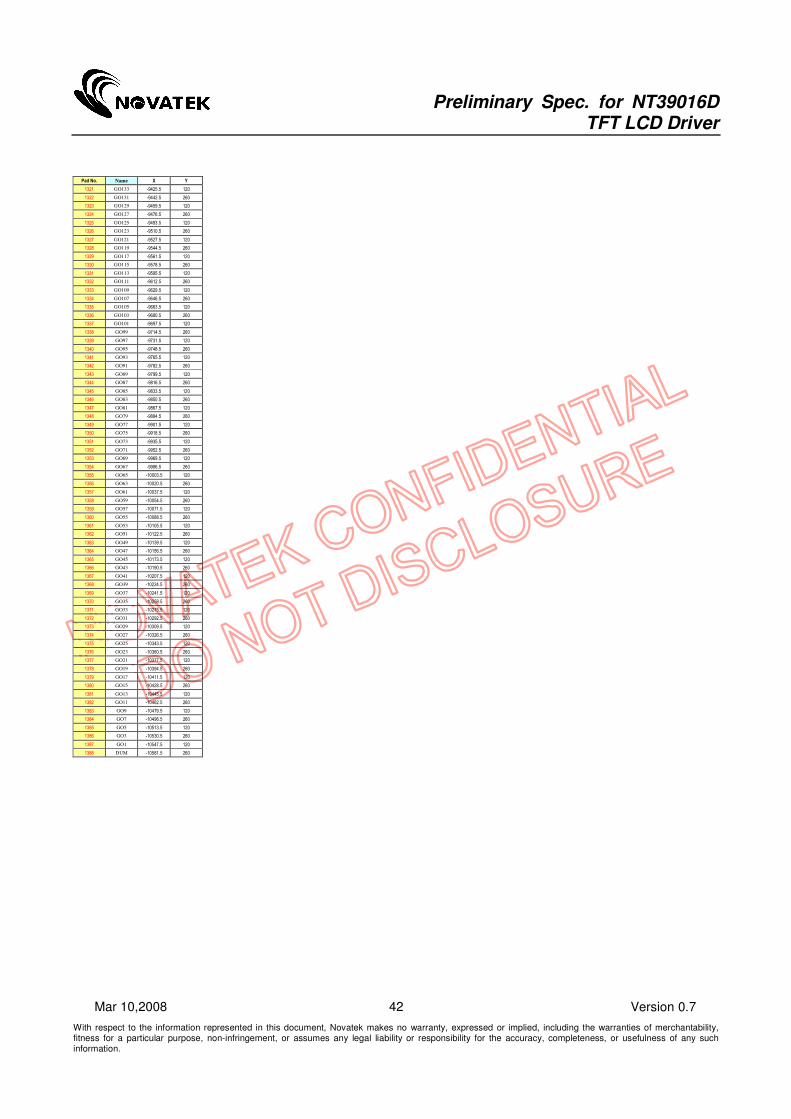
Preliminary Spec. for NT39016D TFT LCD Driver
With respect to the information represented in this document, Novatek makes no warranty, expressed or implied, including the warranties of merchantability, fitness for a particular purpose, non-infringement, or assumes any legal liability or responsibility for the accuracy, completeness, or usefulness of any such information.
42 Version 0.7 Mar 10,2008
Pad No. Name X Y
1321 GO133 -9425.5 120
1322 GO131 -9442.5 260
1323 GO129 -9459.5 120
1324 GO127 -9476.5 260
1325 GO125 -9493.5 120
1326 GO123 -9510.5 260
1327 GO121 -9527.5 120
1328 GO119 -9544.5 260
1329 GO117 -9561.5 120
1330 GO115 -9578.5 260
1331 GO113 -9595.5 120
1332 GO111 -9612.5 260
1333 GO109 -9629.5 120
1334 GO107 -9646.5 260
1335 GO105 -9663.5 120
1336 GO103 -9680.5 260
1337 GO101 -9697.5 120
1338 GO99 -9714.5 260
1339 GO97 -9731.5 120
1340 GO95 -9748.5 260
1341 GO93 -9765.5 120
1342 GO91 -9782.5 260
1343 GO89 -9799.5 120
1344 GO87 -9816.5 260
1345 GO85 -9833.5 120
1346 GO83 -9850.5 260
1347 GO81 -9867.5 120
1348 GO79 -9884.5 260
1349 GO77 -9901.5 120
1350 GO75 -9918.5 260
1351 GO73 -9935.5 120
1352 GO71 -9952.5 260
1353 GO69 -9969.5 120
1354 GO67 -9986.5 260
1355 GO65 -10003.5 120
1356 GO63 -10020.5 260
1357 GO61 -10037.5 120
1358 GO59 -10054.5 260
1359 GO57 -10071.5 120
1360 GO55 -10088.5 260
1361 GO53 -10105.5 120
1362 GO51 -10122.5 260
1363 GO49 -10139.5 120
1364 GO47 -10156.5 260
1365 GO45 -10173.5 120
1366 GO43 -10190.5 260
1367 GO41 -10207.5 120
1368 GO39 -10224.5 260
1369 GO37 -10241.5 120
1370 GO35 -10258.5 260
1371 GO33 -10275.5 120
1372 GO31 -10292.5 260
1373 GO29 -10309.5 120
1374 GO27 -10326.5 260
1375 GO25 -10343.5 120
1376 GO23 -10360.5 260
1377 GO21 -10377.5 120
1378 GO19 -10394.5 260
1379 GO17 -10411.5 120
1380 GO15 -10428.5 260
1381 GO13 -10445.5 120
1382 GO11 -10462.5 260
1383 GO9 -10479.5 120
1384 GO7 -10496.5 260
1385 GO5 -10513.5 120
1386 GO3 -10530.5 260
1387 GO1 -10547.5 120
1388 DUM -10581.5 260