ntrs.nasa.gov · · 2016-06-07, j ! i i i | ' [spacecraft for two pioneer venus mission_ are...
TRANSCRIPT

+•+= ,+}: • I
° i!:r
/?!.
Ii 1. 1n,roau_tion 2_,2. Charg0d Particle Envlr, nment 299
.i::, 3. S_aeeernft Electrical Model 30312 4. ISPICE CalculationReSults 30c+:_. l_eferences 308
,,°,i+
!,,t:
j, _2
=,,_ if''
+i:!: 5. Pioneer Venus Spacecraft:_: Charging Model
....° _:: P.A. Robltlson, Jr. ond A.6. Holmo,HughesAir+raftCompany
+'_+i'. SPaceond C:t+mmunlcationsGroup
+:}_+' _I Segun&.CMilcmio
,* Abstract
+!:,,+.+" Large potential differences between pat'ts of the spacecraRs or between thei.:: sp_ceCrtttt and the plasma willcause instruments tO give misleading or meatting-%.: less data. Potentials and cut, rents at various locations on the Pioneer Venus
_ _+ Orbitez' a_'e predicted by ConstruCtin_ a_ elet:trical model of the Spacecraft and the° _ '. environment, anti _alcUlatin_ the response of the electrical r_odel to the envir_)n-
o*i merit moti_l.
....!:..: Five environment mOdels wei-e constructed to r_present the solar wind and theupper_ middle, and lower ioaospllereofVenus. The spacecraftstructurewas'++_, modeled _#lth over 140 passive electrical elemehts representing structural elements
of the sp_ce_'.rtfft. Electron, ibn, secondary electrgn , and photocurrents to th__+:ii) spaeecrMt from thepl_sma wer_ calculated,i/_norlngsheatheffects. •
"_' In all but one ease, potentials of interest were less than 1 volt. Potential
_. differences between _#idely s_pat.ated points off the equipment shelf were less thant inV. The one ar_a at co_icerttis thest)tarpanel potei_tial_#henthe orbiterispassing throtighthebowshock region. Here We ass1_rfleda hl_hpho_ocur_'entand a
°*°°,!'' low density, low tempex'att_r_ plasma, *tth solar panel poterltials appt'oaehing 5
•i+ volts positive. Some experimenters indicated this would present a problem in, ,, ihterpreting results. Furth_i" study is needed to clai-lfy this issue; otherwise,
° _ , spacecraftpotentialsare well withindesignlevels.
::_ _/ork performed by HUghes fop Ames Reseai-ch Center under Contract NAS 28300.
..... 297
°i , '
:+ ++::++++.+++....:+++++ ,°.:+:......": + ......+ ..... + ' uuuuuuu,-+-oe,,^_'^'_'_'_'_'-_'°^,",.)"
https://ntrs.nasa.gov/search.jsp?R=19780002205 2018-06-29T10:14:52+00:00Z
, J ! I I I | ' [
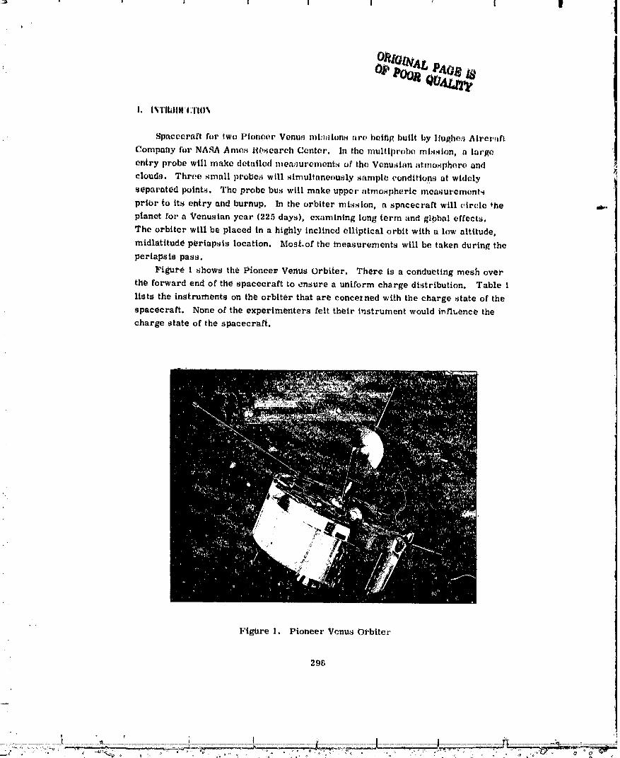
Spacecraft for two Pioneer Venus mission_ are bclflg built by Ilul_hc,_Aircraft
Company for NASA ,_mea Research Center. In the multiprobe mission° a large
entry probe will make detailed measurements of the Vcnusian atmosphere and
clouda. Three small probes will simultane,_usly sampl_ conditions at widely
separated points. The probe bus will make upper atmospheric measurements
prior to its entry and burnup, hi the orbiter mission, a spacecraft will circle _he .._.,
planet for a Venusian year (225 days), examining long term and global effects.
The orbiter will be placed in a highly inclined elliptical orbit with a low altitude,
midlatitudd p_riapsis location. MoaLof the measurements will be taken during theperiapsia pass,
Figure 1 shows the Pioneer. Venus Orbiter, There is a conducting mesh over
the forward end of the spacecraft to ensure a uniform charge distribution, Table l
lists the instruments on the orbiter that are concerned with the charge state of the
spacecraft, None of the experimenters felt their instrument would int2_ence the
charge state of the spacecraft,
Figure 1. Pioneer Venus Oi-blter
29[,
00000004-TSA14

,%
J
/
/
/
Table 1. E_tpe_lnlents Concerned with Charge State of Spacecraft
u ]
I Opetatlh0Instrument Attitude I_portdlnt Feat_J_s
lot. massspectd)met0r <5000 km No externalpot_dtials;currentOr. Harry Ta_lor _ x 1014 A. 2 in. dla apertdre;
WOUldpref0r ne_atil/eiVchb_gedspacecraft a_-
_-Iehtrbntempereitur_I_btm >6000 k_ _.kWo_dpotentibts_r¥ fromDr. LarryBrace -5 to +7 V; total ai'ee_13 cruZ;
singleprobearea = 4 cm2
Retardingpotential lanalyT_r Js,i[ ExpOsedpJteritial +6 V currentDr. WilliarfiKnudsen to instrUmehtcouldbe aShi{ih
a_ 10.4 A; aperturediameter= 8 _m;would preferspace-_:raftpotential from -1 tb ,5 V.
Plasmaanalyzer All Potential ±700 V; rn,_xirhdm[_r. ,JOhnWOlfe curr_nt lb-12 A; al_erture
ar_l = 1 cm2
Electric fielddetectt)r All No exposedpotentials;tneasuresDr. Fred Scarf potential difference4crosl
instkUmentat frequenciesabove100 Hz
:2. CIIARGEI_PARTICLE ENVIRON_|ENT
The charged particle environment for the Piotleer VenUs Orbiter tLli"sion is
an upper bound on empirical information vbtalned from Various sources, t -4 The-
model covers the full range of _ltttudes where scientific packages on the orbiter
vehicle are bperatiotlttl. The tootle1 is summarized in-Table 2.
Table 2. Pioneer Venus Orbiter- Charged P_trticle Environment
MaxiMuM EhergyRe0ion Erlvirkmmdnt AltitUde Charged D6hsitiq, Lev(_ls.Label Compondnt Rahge.Krh Partields per _m" eV
I Shierwind _ to 1{)00 l_rotbnt 10 10 to 100eiactYons 10 10 to 100
II Ul_t_er 100011o700 Ibns (C02+) 102 _1.|ion_Kihere elec|rbns 1_}2 _0.1
III MiLILli_ 700 11o350 Ions(CO2+) I_ 3 <0.1ionos[_here electrons 1b3 <0.1
IV Lower 350 .o2{)0 Ions(CO2+) _ x 104 <0. iionosphere| electrons 5 x 10⁴ <0.i
V Lower 200 tc 150 Ions(CO2+) 6 x 10_ "0.06ionosi)here2 electrons _ x 105 _0.06
299

, i I I I I ! i II
/
A eo_mie ray backg_O_! 5 _ili be preSeht at all alt_tu'Jes. Since the cUrrent-
densities are l_W and the particle energies high, there will be negligible contribU-
tion to _ surface charge Or potential buildup Ot_the o_biter exterior sur..ces froln
th[s source. The solar v_ind con_ponent of the envi_,onment dominates down to an
altitude of approximately 1000 kin, the bowshock _egion (actual altitude strongly
dependent on vehicle trajectory). The ionosphere begins to develop at lower
altitudes and p_rticl_ _d current denSitieS peak at an altitude in the range of 150
to 200 kin (- _00°K thermosphere).
The toiL.Sphere is extremely dynamic and the altitudes bounding the regions of
interest should not be taker1 aS rigid divisionS. In addition, the Solar radiation
(- 5_50°K blackbody, 2.7 X 10"4erg_/cm 9 Sec) at Venus contribUteS strongly to
the spacecraft charge for the orbiter because of the.ef_ect-o£ photoez,_ission from
the spacecraft external surfaces.
Electron and ion currents, photoemission cUri-entS0 and second&ry _h, ctron
currents are included as appropriate. Tables 3 and 4 list current density (a,_iperes
per squa_'e ce_Itim_ter) used in calculations for each region. These current densi-
ties are one-half the expected maximum therm_tl curretits. The secondary e1_ctron
current iS dependent on a parameter Emax, the energy at r_aximUm secondaryelectr-on emis_n_ T_ble 4 lists the Secondary electron _missi_n for t_o t_ical
Ema x _md Sma x -- I. Srribx is the rhlr_ber of secondary electr_r_ en_itted at Ema x.The resistivity of the plasma is calculated from kinetic theory. 6 h_ calculatlng
the resistance to the plasma from each element, the Debye length 6 was used as the
length through the plasma. Table 5 lists the terms included in s power ser_es t
expansiori of current verSuS potential .........
KEY FOR TABLES 3.THROUGH 5
ALT _-altitude range _ = collision freqt_ency
Ne = electron density, eleetrbn/cm 3 Je = electi-on cuerent density
lt.Te = electron tempei_ature0 eV Ji = i{m eurrent density
_tD = /. kT .¥/2 ffiDebye length, cm Je/e -- s_condary electron
JhU = photoemission current
-- _eC2y = kineti,, th_bry r_sistivit_F_ densityNee2 J =totai current density
300
O0000004-TSB02

/
r_
!_ Table 3. Plasma P_ra_et_-,'S
f I
• .,ti,o.a oh2:om:_ R_gi_)h km • C_
_, I ooto 1000 10 100 2,3S d 103 3.194 x 10³• Soldr Wind
! II 1000 tO 700 100 0.1- 23.6 2.8 x 10_ii" ill 700 to 350 103 0.1 7.4:3 2.5 x 10⁷
:::, IV 380 to 200 5k 104 0.1 1.05 5.0x 10⁸
_!'_i: V 200 to 150 5.0 x 10⁵ 0.06 0.26 5.0 x 10⁴
_i: Table 4.... Plasma Currents USed if_Caleulatiorts*
!i, J_/oo.}_:: Jeo, Jio, E = :_JO0 J_/eo, Jhu' .__: Re(iion A/cm2 AlUm2 A/cm2 E-400 Alcm =
)_ I Solarwihtl 1.34x 10"10 3.13x 10"12 1.38 x 10"12 1.12 x 10"12 6x 10"g} _' II 4.24 _(10"11 9.89 x lt_"13 1.01 x ,0"12 /.6 x 10"13 3 x 10.9
Iii 4.24x 10"10 9.89x 10"12 1.01 x 10"11 7.6x 10"12 0
:_ IV 2.12 x 10.8 4.94 x 10"10 5.0P:x i0 "10 3.81 x 10"10 0i_ V 1.(_4x 10.7 3.133x 10.9 3,94 J(10.9 2.9? x 10.9 0'. ,, ,
_i Table 5. Power Series Expanslon of Total Currer.t DeP._ity"_ in One Dtmertston
_! _ [.&.%_i_ -*_Ti Je = e = Jeo_-e_)/kT=! _ _,,_c21
'!' ' Ji = _. Je ee _/kT = JiOe e _)/kT
4 kT 1/,;,' Je/eo = J_(7.4) Stnak 1 .,kT/Emax (1;kT_ i 1/2 1-,rf; ' ' Ema_t _Er_x /
'_ le/e = le/eo e +2/__/kT
_ J " Jh(_+Ji + Jr/e . ae
_" l = (Jhd _'llo +Je/_o" JebJ + (Jio +2 j_/eo + Ji_o)
+ (lio + 16Je/eo- leo) 1/24 + . , .
o!
• One-hal_ tfia_lmUtn values.
30t
_'_;:;_ ..........................! _.........................................._ :_" '_............._'...................................................._......................... J_ ....... J"' n_i _.;
O0000004-TSBO3
:i_:_i:_'
_ 4!
'L: !
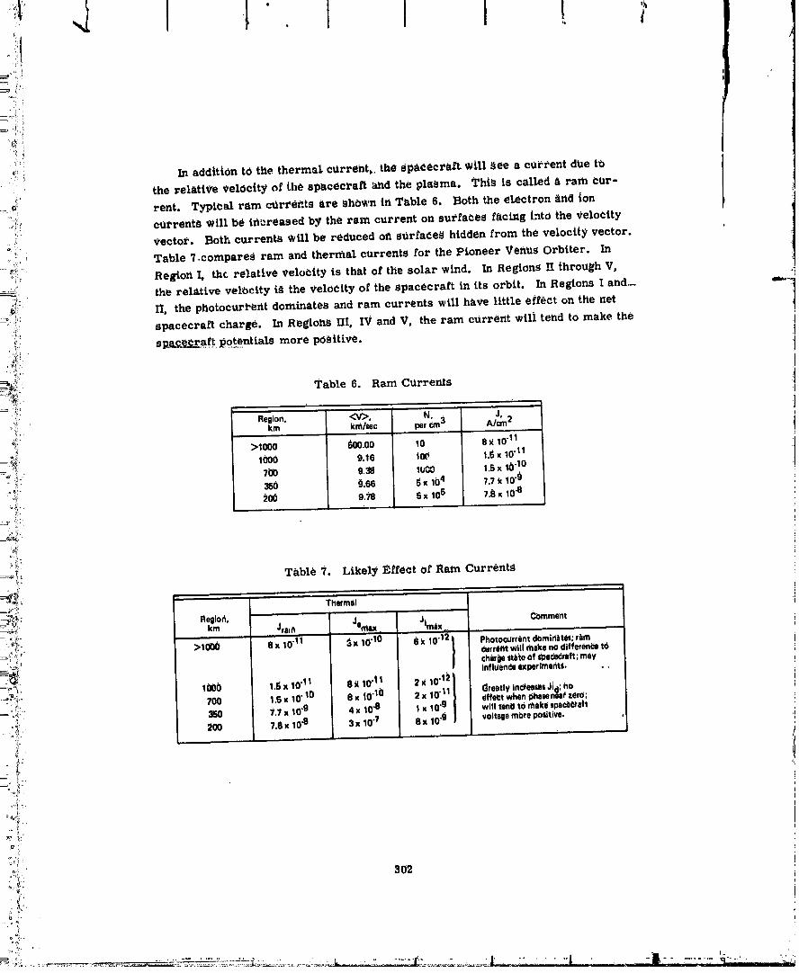
_:'i In addRt0n tO the thermal cUrreht_, the spad_crsrt will See a current due to
:_: the _-elatl_e velocity ,_f [he spacec_'aft and the plasma. This is called _ ram eUr-
::_ rent. Typical ram c_r_'ents are ShOwn in Table 6. Both the electron _nd Ion_f c_rrent_ will be i_reased b_ the ram current on sutfa_es f&clng into the Velocity
K,
=!: Vector. Both currents Will be reduced off s_rfadeS hidden from the velocity vector.
":,:u Table ?.compared ram and thermal currents for the Pioneer Ven_s Orbiter. In
_:!:: ReEion I, the relative Velocity is that of the solar wind. In Regions 11_hrough V,
_:: the rel_tive velocity is the _'eloeity of the spacecraR in its orbit. In Regions I and._ _.
_ 11, the photocurl-ent dominates and ram currents will have little effect on the net
_! spacecra_ charge. In RegiohS HI, IV and V, the ram current wilt tend to make the
_i!i s_a_t _otentialS more pea|tire.
%-
_=_ Table 6. Ram C_rrents
Region. <V>, N:_3 J,;_':- km krfi/lec pe_ A/cm2
o_: >1o0o #d)o.oo lO 8_ 1o"1i_°_i' 1000 9.16 tOt_ 1.1_x 10"11=_ _.' 7U0 938 I_ 1.5x 10"10
_°i:" 350 _1.66 _ X Ib 4 7.7 _k10"§Q*_i '_0 9.78 6 x 10⁵ 7.1_x 10.8
• r
_t,. T_tble?. LikelyEffeetofRam Currents
':_ : Fleglon. " Cbmmentkm Jralfl Jemex JIm_x
:_:_'".: >'100() S x 10"11 3; 10"ld _ k 10"12 t Photoc_rrentinfluimcedominJt0/; r_mchirp ltizie of Ipe_edreft;may
experimal_tS.
_< 1000 1.5 x 10"11 8 _ 10"1! 2 x 10"I__,. Greatly inOee_s JJd;hO-' ;::, 700 1,5 x 10"10 0 x t0 "10 2 x 10"11 effect when i_he_ene#zerO;
:_ 350 "t.7x 10.9 4 x i0 .8 1 x 10"g will tentl td rhekemace,'eft
:'_/ 200 7.8 x 10.8 3 x 10.7 8 x 10"_ voltagembre po_dtlve. 0..... a ,,, , .
2: I:' s'
:'_):: 302
1
O0000004-TSNOd
3., SP,*.CECIIAI"TEI,E/:TIIIC,_.I, _IODI.:I,
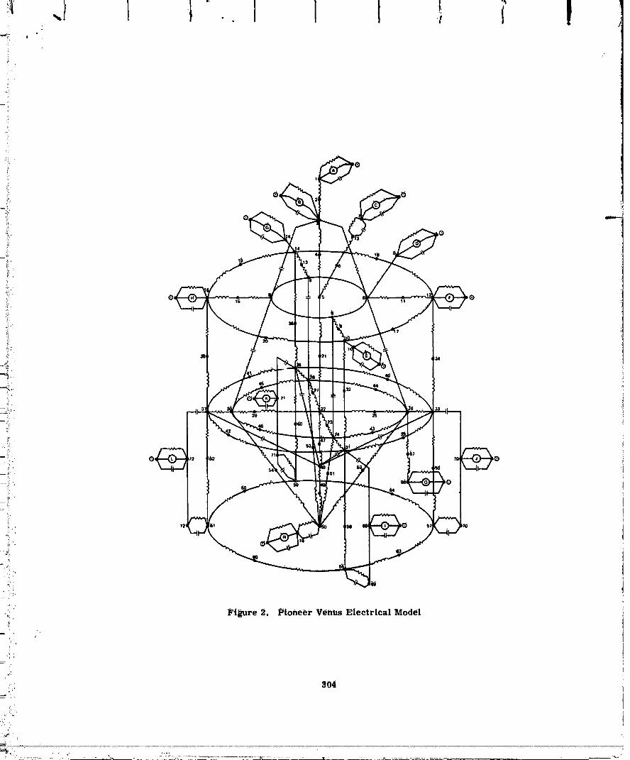
The electricalmodel for theorbiterincludesmore than 140 electricalele-
mentS and over 70 _todes, each representingan importantspacecrEtft location (see
Figure 2). This electricalmodel was construe:tedas describedIn7 and the follow-
ing discussionoutlinesthe tot'tnulationof themodels. !
-i3.1 ThFustCone (Series l_-
The magnesium thrUgtcone was modeled as a seriesof linearindt_Ctorsand
resistors.A centralnode was U_ed toprovidea locationfora capacitancetothe
_urroundingsolar panelsubstrate. The lower end ofthe cone was tieddirectlyto
the equipment shelfsupportstrUtsand the upper end representetithe interface
withthe BAPTA at_tiequipment shelf.
3.2 EquipmentShelf SupportSlruts (Series 201
The 12 supportstrut_were reduced to an eqt_tvalentconfigurationoffourto
fitthe simplifiedquadrantmodel o_the equipment shelvesantlsurroundingsolar
panel_iantisubstrate. The fourstrutelements were thenmodeled as linearirtduC-
totsantiresistOrS, Estifnatedresistancesofbonded jolntswere Inchtdedwhere
itwas feltimportant.
3.3 EquipmentShell'(Series 30)
The equipment _helfwas modeled inquadrantswithcircumferentialand radial
inductancesand reslstance_calculatedforeach. A capacitancetothe forward
aluminum mesh and thermal blanketwas alsoincluded. (Where two capacitances
appear inserieswithan unimportant interveningnode antlone ismuch lar_erin
magnitude thanthe other,the largercapacitanceisomittedL*om themodel tor
s{nlplificatton, Or an equivalentcalculated.)
3.4 B._,PT_. _mdI_._PTASttl_pbftCofle(Setie_ _0)
The BAPTA anti its _upport structure were modeled a_ an inductor and resistor
tied at the efitis to the equipment shell and the m_tm antenna supports,
3,5 MiainAntennaSgpport, Dish, and Forwm'dOmni(Series 50)
The alOminum antenna support structui'es we/'e fiiodeied as linear ittductors
ai_d resistors writ s node at the main dish arid St the oii_ni. Capacitances were
catcul/ated for the dish and the omnl to in[frilly. An estimate of mtttual tridtzctattce
: co_ipllng with the at_t_rma feed sti'iictiire Was also included.
' ' .......................... TSB05....... ...................... 00000004-


I. ISPULE CM.(;IL_TIO% |U_._I_I.T_
The re_ultd of the Table 3 c_Prents used orlthe ele_tPicalmodel are presented
in Table 8. Iri Regions l and I_1, the photocurrent was modeled as an offset sine
function with the phase angle dependin£ on the quadrant, For example, SourCe t
has a phase ot 0 °, J has a phase of 90 °, etc. The offset ts chosen to make the
photoeul-tent maximum at 90 o and _ero at 2_0 °. This overestimates the photo-
current per spilt cycle. A rectified sthe curve would better approximate the photo-
current. I_ these regions, the effect of this pulsating cUrrent is seen as an aC
voltage on the perimeter of the shelf. The magnitude o_ this voltage is shown in
Regions I and Ii at the four shelf locations and for the exterior of the solar panel, t
The frequency for this oscillation is the reciprocal ot the spacecraft spin period.
The only voltage to exceed i volt in Table 8 is that oP the solar panel in
Region II. Here we assume a fairly high photocurrent and a very low plasma
temperature and density. The electron eUrrerit is predomlnately a thermal current,
_ the only current available to rieutralizethe phOtocUrrent. Therefore, positive _
potentiMs are possible.+
-{ Table 8. ISPICE Calculatlohs -85 Percent Porosity
Aitltud0(mix) 200 350 700 1000 >1000 km
-: Re_liCln V IV III II I,,,,,,
Node I_PICERun liJV6 PV§ PV4 PV3 PV2
_: 1 Orflniantehna .3.4 -11 .37 < 1 24
:: 3 DiShantenna .1.9 .9.8 .37 < 1 :_4: ? Ahtennbf_l .1.{} ._._ 42 <1 _1
_: 8 Mesh .1.9 .g.2 .37 <:I _4_: 16 Sol_ pan'e|e_tehsion .1.9 -9.2 -37 <1 _4_.0.04
:_2 CehterOfihelf -1.9 -9.2 .37 <1 24
1 "t24 E;helf0a -1.9 .I).2 -37 <1
2_ _;heif{)0b .1.9 -g.2 -31 <1 ±4]J 24 #.0.04_" 28 Shelf180° -1.9 .9.2 -37 24
30 Sh_tt2_0o 4.a -0.2 -3i 24' 72 Sdl_rp_inel -1.9 -9.2 -41 2344" 21 + 20: 74 Aft cavity -_17 -78 -91 -92 .54
R40N| Currentti_roughBAPTA,/_ -2.3 -17 .1.1 13.6 .7.8
"13.:J33inV.i;, NO'J"E: Ailvoltdljesinmillivolfsuhlessdth_nNiSbn()Jed.
3O6
,!
.i: .Ltiii,i-_::'.;_.i_:;_i i_"/:C...... _ _'-
........ O0000004-TSBO8

I F I. 1 t f t -! I
r-:°,_ voltages tot each regiort, in Negto_s I and Ii, the photocurrent still dominates _tnd
the voltages remain about the same.
iJ2;:', IflereasLfig the conductive mesh area does not slgnltleantly change the potentials
i;L_ on the spacecraft. Table 9 shows a series of Caldulatio_s in which the area or the
i=_ i conductive mesh is calculated, assuming 0 percent porosity instead of 85 percent
porosity. Modeling of the plasma i_rkdthe spacecraft in this way is a riew art and
__•:_i there life many area_ of uneertalnty. In extending these calculations, the ISPiCE 8_-i_}:i representatioll of nonlinear voltage controlled current sources for low temperature
i_i:i plasmas needs improvement, as does tile representatiori of photocUrrents on a
i-__. Spinning body. Tl_e _ffect of ram current_ as a funCtiori or orbit position and orien.-
i _, tahon, arid the investigation o£ sheath format_m0 plasma resistivity, and geomet-}" _" rical effects are also ot interest.
,,_, Table 9. ISP[CE Calculations - 0 Percent Porosity
_,.jj,
2 g2,', Altitutle (fllag) 200 35(_ 7_0 1000 >1000 km
_;;_N_: RegiOn V IV III Ii I
*_'-,_: N0_e ISPICE Run PV6 PV5 PV4 PV3 PV2
_-:,_' 1 Oi_ni antehna .3.4 -1 | -40 < 1 11. 3 _i_h ant_nn_ .1.g -9.8 -4_ <1 11
_ ":_ Ant_nhe fe_l .1._} .g.5 -42 <1 21
_=:;!:_ S Mest_ .1.0 .9,2 .40 <1 10k :_i. 11_ Solarpanelextension -1.9 .9.2 -40 <t 10_- J_: 22 Centerof shelf -1.9 .9.2 -4_ <1 10
_. _4 Shelf edge0° .1.{) -9.2 .40 < 1 10
i:_o::_' 26 Sh_lf edge90b -1.9 -g.2 -40 <1 .+.4/J 10 .¢13__i_ i 28 Shelf_d_e 1S0° .1,8 .9,2 -40 <1 10;
,_'_ 30 Shelfedge2?00 .1.9 ._.2 -40 <1 10j!_L.. _
!_'_ ' 72 Solarpanel -1.9 .g.3 .40 2344 ° 21!_,..._o_, 74 Artcavity ._17 -18 .01 .91_ .S4__°zi-_' R40N1 Cmrent throughBAPTA,/)A -2.4 .18 .0.5 13.6 33
i=-):_ NOTS: All voltagesin millivolls uhletsotherwisenoted.
_L
i ;L!,- 307i :i!
_ ;!'.
_,, o_, . ....... _ ................... ................ ______-........ J ..... - ..... : :. -O0000004-TSB09

[ 1 f ' Ig
Re[etences
I. Cloutie/-, P.A., et at (1974) Pl_neta_'y Space Science, 2,_2:967-,q90.
2. Kuma_', S., And Hhnten. I;). (1914)J.Geophys. t'-s. '/,_(No. 16):2529-2532.3. Stewart, R.W. (1971) J,Atm_s. Sel. 28:1069-10 ....
4. Whitten, R.C., and Colin, L. (1974) Re%,. ot Geophy_. snd Space Physics12(No. 2).155-192.
5. Binder, D., Smith, E.C., and Holman0 A.B. (1975)IEEE Transactions on _.,,NUclear Scle_i_eNS-222(No. _):2_75-2680.
6. Spit_er, L. Jr. (19_2) physics ot Fully Ionized Gases, Interscierlce.
7. DEM.P Analysis of HS-ZXX Spacecraft (1974) Intelcom Rad Tech, INTEL-RT6045-004.
8. ISPICE Reference Guide (1974) t_iational CSS, Inc. 0 (Proprietary to NCSS, Inc).
308
J
O0000004-TSBIO