nuclear equipment manufacture.pdf
TRANSCRIPT

8/13/2019 Nuclear equipment manufacture.pdf
http://slidepdf.com/reader/full/nuclear-equipment-manufacturepdf 1/14
The Babcock & Wilcox Company
Steam 41 /Nuclear Equipment Manufacture 50-1
Chapter 50
Nuclear Equipment Manufacture
Many manufacturing operations for nuclear steam
supply system components are similar to those usedfor fabricating fossil fueled equipment. However, theunique requirements and geometry of nuclear com-ponents call for special manufacturing methods,equipment and facilities. Nuclear equipment mustoperate reliably with minimal maintenance becauseof its operating environment. For this reason there arerigorous equipment specifications by customers andregulatory authorities. Quality assurance require-ments are stringent and special attention must begiven to cleanliness and material control.
Selecting the manufacturing sequence and meth-ods requires balancing design requirements withmanufacturing capabilities while meeting commercial
obligations. As a result, special equipment and fabri-cation sequences are usually required.
Typical component description
Commercial nuclear components are typically cy-lindrical pressure vessels. Some of the components arelarge and heavy and require customized shipping andhandling arrangements. Reactor vessels and compo-nents for pressurized water reactor (PWR) systems upto 32 ft (9.75 m) in diameter, 125 ft (38.1 m) long andweighing 1000 t (907 tm) have been built by The Bab-cock & Wilcox Company (B&W). Some nuclear compo-nents also have close assembly tolerances. This requires
specialized equipment and extraordinary care duringmachining and welding operations.
Manufacture of reactor vessel componentsDifferent reactor systems have differing reactor ves-
sel designs. B&W has experience in several systems,including the PWR, which is the focus of this chapter.
Each reactor vessel is made up of a cylindrical mainsection and two hemispherically shaped heads. Thereactor closure head is attached by a bolted flange andhas several penetrations for the reactor control rods,venting and/or instrumentation (Fig. 1). Control rod
drive mechanism (CRDM) tubes penetrate the hemi-
spherical section and are welded at the inside surface.Similar tubes for venting and instrumentation mayalso be present, and follow the same general arrange-ment. In recent years, plant owners have replacedreactor closure heads because of stress corrosion crack-ing of the weld between the head and the reactorCRDM tubes, and boric acid wastage of the carbonsteel base material. (See Chapter 46.) The inside of the reactor vessel includes many attachments for thefuel support system. (See Chapter 49.) Since therehave been no reactor vessels manufactured recentlyby B&W, this section will only focus on reactor vesselcomponents, such as the reactor closure head.
Fabrication of replacement reactor vessel closure heads
The closure head has a hemispherical dome with abolting ring flange. The closure heads for typical B&Wreactors measure 16.67 ft (5.08 m) outside diameter(OD), with a dome radius of approximately 7.25 ft(2.21 m) and a nominal dome thickness of 7 in. (178mm). The bolting ring flange is 30 in. (762 mm) thick.
Fig. 1 Reactor vessel closure head.
8/13/2019 Nuclear equipment manufacture.pdf
http://slidepdf.com/reader/full/nuclear-equipment-manufacturepdf 2/14
The Babcock & Wilcox Company
50-2 Steam 41 /Nuclear Equipment Manufacture
Typical replacement closure heads are fabricated froma one-piece forging. This eliminates the periodic in-service inspection required for pressure boundarywelds. Large diameter heads may have their hemi-spherical portion made from a single forged partialhemisphere with additional forged rings or segmentsthat are welded together. The bolting ring is forgedseparately and welded to the hemisphere. All reactorcomponents made of ferritic material have their inter-
nal surfaces clad with austenitic stainless steel orInconel®to provide resistance to corrosion from the reac-tor coolant. The cladding can be applied using variouswelding methods such as submerged arc welding (SAW)or gas metal arc welding (GMAW) using wire or strip.
Critical features There are several critical featureson the closure head that must be fabricated to closetolerances. The gasket surface on the bolting ringmust be flat and have the required surface textureand lay to ensure a leak-tight joint. The CRDM cen-ter lines must be true to the axis of the head and theCRDM tube diameters must be held within tightlycontrolled tolerances to ensure that the operation of the control rods is not hampered in any way. The weld
between the CRDM tube and the head is designed andfabricated to avoid residual stress and to maintain theposition of the CRDM tube. It is critical to control re-sidual stresses during the manufacturing process toavoid stress corrosion cracking of the closure headduring operation. Residual stress is controlled duringmanufacture by limiting the cold work and byelectropolishing the CRDM tubes and welds.
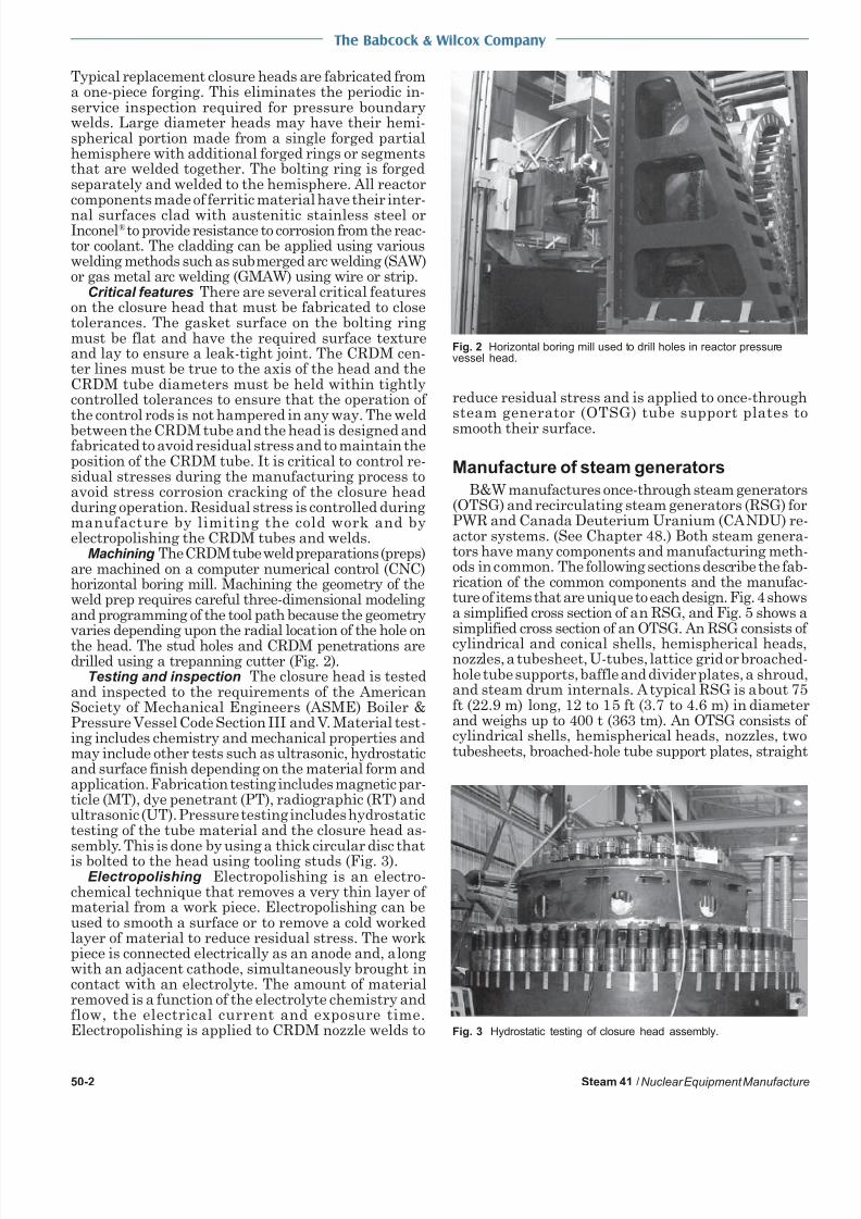
Machining The CRDM tube weld preparations (preps)are machined on a computer numerical control (CNC)horizontal boring mill. Machining the geometry of theweld prep requires careful three-dimensional modelingand programming of the tool path because the geometryvaries depending upon the radial location of the hole onthe head. The stud holes and CRDM penetrations aredrilled using a trepanning cutter (Fig. 2).
Testing and inspection The closure head is testedand inspected to the requirements of the AmericanSociety of Mechanical Engineers (ASME) Boiler &Pressure Vessel Code Section III and V. Material test-ing includes chemistry and mechanical properties andmay include other tests such as ultrasonic, hydrostaticand surface finish depending on the material form andapplication. Fabrication testing includes magnetic par-ticle (MT), dye penetrant (PT), radiographic (RT) andultrasonic (UT). Pressure testing includes hydrostatictesting of the tube material and the closure head as-sembly. This is done by using a thick circular disc thatis bolted to the head using tooling studs (Fig. 3).
Electropolishing Electropolishing is an electro-chemical technique that removes a very thin layer of material from a work piece. Electropolishing can beused to smooth a surface or to remove a cold workedlayer of material to reduce residual stress. The workpiece is connected electrically as an anode and, alongwith an adjacent cathode, simultaneously brought incontact with an electrolyte. The amount of materialremoved is a function of the electrolyte chemistry andflow, the electrical current and exposure time.Electropolishing is applied to CRDM nozzle welds to
reduce residual stress and is applied to once-throughsteam generator (OTSG) tube support plates to
smooth their surface.
Manufacture of steam generators
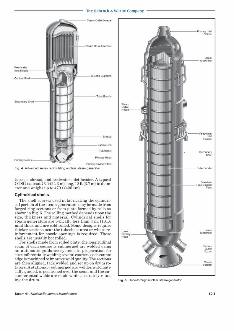
B&W manufactures once-through steam generators(OTSG) and recirculating steam generators (RSG) forPWR and Canada Deuterium Uranium (CANDU) reactor systems. (See Chapter 48.) Both steam generators have many components and manufacturing methods in common. The following sections describe the fabrication of the common components and the manufacture of items that are unique to each design. Fig. 4 showsa simplified cross section of an RSG, and Fig. 5 shows asimplified cross section of an OTSG. An RSG consists of
cylindrical and conical shells, hemispherical headsnozzles, a tubesheet, U-tubes, lattice grid or broachedhole tube supports, baffle and divider plates, a shroudand steam drum internals. A typical RSG is about 75ft (22.9 m) long, 12 to 15 ft (3.7 to 4.6 m) in diameterand weighs up to 400 t (363 tm). An OTSG consists ofcylindrical shells, hemispherical heads, nozzles, twotubesheets, broached-hole tube support plates, straight
Fig. 3 Hydrostatic testing of closure head assembly.
Fig. 2 Horizontal boring mill used to drill holes in reactor pressurevessel head.
8/13/2019 Nuclear equipment manufacture.pdf
http://slidepdf.com/reader/full/nuclear-equipment-manufacturepdf 3/14
The Babcock & Wilcox Company
Steam 41 /Nuclear Equipment Manufacture 50-3
tubes, a shroud, and feedwater inlet header. A typicalOTSG is about 73 ft (22.3 m) long, 12 ft (3.7 m) in diam-eter and weighs up to 470 t (426 tm).
Cylindrical shells
The shell courses used in fabricating the cylindri-cal portion of the steam generators may be made fromforged ring sections or from plate formed by rolls asshown in Fig. 6. The rolling method depends upon thesize, thickness and material. Cylindrical shells forsteam generators are typically less than 4 in. (101.6mm) thick and are cold rolled. Some designs requirethicker sections near the tubesheet area or where re-inforcement for nozzle openings is required. Theseshells are usually hot rolled.
For shells made from rolled plate, the longitudinalseam of each course is submerged arc welded usingan automatic guidance system. In preparation forcircumferentially welding several courses, each courseedge is machined to improve weld quality. The sectionsare then aligned, tack welded and set up on drum ro-tators. A stationary submerged arc welder, automati-cally guided, is positioned over the seam and the cir-cumferential welds are made while accurately rotat-ing the drum.
Fig. 4 Advanced series recirculating nuclear steam generator.
Fig. 5 Once-through nuclear steam generator.
8/13/2019 Nuclear equipment manufacture.pdf
http://slidepdf.com/reader/full/nuclear-equipment-manufacturepdf 4/14
The Babcock & Wilcox Company
50-4 Steam 41 /Nuclear Equipment Manufacture
The advantage of using forgings for cylindrical shellsis the elimination of the longitudinal seam. This elimi-nates the cost of making and examining the weld dur-ing manufacture, and eliminates the need to conductin-service inspection of the weld. Forged cylinders canusually be made to tighter diameter tolerances.
Tubesheet manufacture
The tubesheet is made from a forging that can weighup to 80 t (73 tm). The first major manufacturing op-eration is cladding the primary side of the tubesheetwith stainless steal or Inconel using GMAW weldingmethods, discussed in Chapter 38. The tubesheet isheated before, during and after welding using largeelectric heaters. Usually the welding head is movedover the stationary tubesheet, however, in some casesthe tubesheet geometry requires it to be rotated un-der a stationary welding head. In these cases, speedcontrol of the rotator is critical to maintaining weldintegrity. The clad tubesheet is post weld heat treatedto 1125F (607C). The cladding is then machined andexamined using UT. Cladding thickness after machin-ing is typically 0.3125 in. (7.9 mm).
Drilling the holes through which the tubes are in-serted is the most critical operation for tubesheet manu-facture. A typical tubesheet is 24 in. (610 mm) thick andhas up to 15,000 holes or more ranging in diameter from0.5 to 0.875 in. (12.7 to 22 mm), depending upon thetubing size. These holes must be located accurately, beprecise in diameter, and be straight and perpendicularto the tubesheet surface. Variations from perpendicular-ity, often called drill drift, are typically limited to 0.015
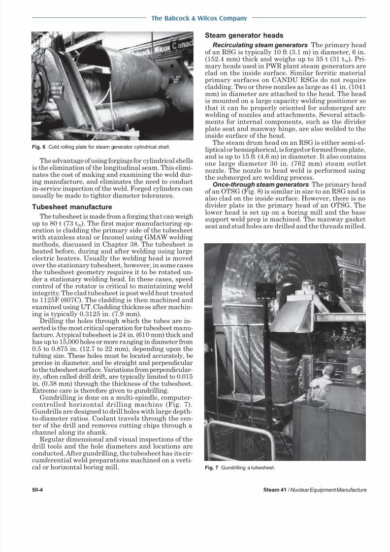
in. (0.38 mm) through the thickness of the tubesheet.Extreme care is therefore given to gundrilling.Gundrilling is done on a multi-spindle, computer-
controlled horizontal drilling machine (Fig. 7).Gundrills are designed to drill holes with large depth-to-diameter ratios. Coolant travels through the cen-ter of the drill and removes cutting chips through achannel along its shank.
Regular dimensional and visual inspections of thedrill tools and the hole diameters and locations areconducted. After gundrilling, the tubesheet has its cir-cumferential weld preparations machined on a verti-cal or horizontal boring mill.
Steam generator heads
Recirculating steam generators The primary headof an RSG is typically 10 ft (3.1 m) in diameter, 6 in(152.4 mm) thick and weighs up to 35 t (31 tm). Primary heads used in PWR plant steam generators areclad on the inside surface. Similar ferritic materiaprimary surfaces on CANDU RSGs do not requirecladding. Two or three nozzles as large as 41 in. (1041
mm) in diameter are attached to the head. The headis mounted on a large capacity welding positioner sothat it can be properly oriented for submerged arcwelding of nozzles and attachments. Several attachments for internal components, such as the dividerplate seat and manway hinge, are also welded to theinside surface of the head.
The steam drum head on an RSG is either semi-el-liptical or hemispherical, is forged or formed from plateand is up to 15 ft (4.6 m) in diameter. It also containsone large diameter 30 in. (762 mm) steam outletnozzle. The nozzle to head weld is performed usingthe submerged arc welding process.
Once-through steam generators The primary head
of an OTSG (Fig. 8) is similar in size to an RSG and isalso clad on the inside surface. However, there is nodivider plate in the primary head of an OTSG. Thelower head is set up on a boring mill and the basesupport weld prep is machined. The manway gasketseat and stud holes are drilled and the threads milled
Fig. 6 Cold rolling plate for steam generator cylindrical shell.
Fig. 7 Gundrilling a tubesheet.

8/13/2019 Nuclear equipment manufacture.pdf
http://slidepdf.com/reader/full/nuclear-equipment-manufacturepdf 5/14
The Babcock & Wilcox Company
Steam 41 /Nuclear Equipment Manufacture 50-5
The base support is fitted and set up on a weldpositioner for submerged arc welding. The primarynozzles are fit and welded using an orbital gas tung-sten arc welder (GTAW) that travels around the weldseam utilizing specialized guidance systems, and videocameras to provide visibility for the operators. Thisequipment is necessary due to the restricted accessaround the weld seam created by the base support.
All nozzle welds are backclad to ensure that there is a
continuous corrosion resistant cladding on surfaces incontact with primary side water. The welds then re-ceive a post weld heat treatment (PWHT) and volu-metric examination by ultrasonic testing (UT) or ra-diographic testing (RT), and surface examination us-ing magnetic particle (MT) or dye penetrant testing(PT). The head is then set up on a vertical boring milland the base support and circumferential seam weldprep are machined.
Pressure boundary assembly
Pressure boundary components include the cylin-drical shells, heads, the tubesheet, and external and
internal supports. Alignment, welding, nondestructive examination
(NDE), PWHT and machining are critical operationswhen assembling these components. The sequence of adding nozzles and attachments depends on the ac-curacy requirements and anticipated weld distortionduring assembly. If there are tight tolerance require-ments on the location of nozzles and attachments,these features are machined after final assembly andPWHT of the pressure boundary components. How-ever, this adds to the critical path schedule and, whereit can be accommodated, these features are attachedto the individual components and machined prior tocomponent assembly.
Circumferential weld seams are typically made withsubmerged arc welding (SAW) (Fig. 9). The compo-nents are aligned and then rotated under a station-ary submerged arc weld head. The welds are gener-ally two-sided (first welded on the inside and then onthe outside of the wall thickness) so that the root of the weld can be ground clear prior to welding the op-posite side. If access to the inside is restricted, thewelds are one-sided and are made from the outside.
This requires precise alignment of the mating weldpreps to avoid any defects at the root of the weld. Thisarea may have restricted access for grinding and ex-amining the surface. The welds receive surface NDE(MT, PT) and volumetric NDE (UT, RT). The ASMECode specifies when these examinations shall be madewith respect to the PWHT.
The OTSG pressure boundary assembly has someunique differences from an RSG, mainly because thesecond tubesheet must be installed after the shroudand tube bundle supports are installed. The lower pri-mary head is installed after the tubes are inserted.This sequence is explained in more detail later in thischapter.
Pressure boundary post weld heat treatment PWHTis an important consideration in planning the assem-bly of a steam generator. All carbon steel pressureboundary welds require PWHT. In the assembly se-quence, these welds must be accessible for NDE afterPWHT, as specified by the ASME Code (Fig. 10).PWHT is conducted on as large an assembly as pos-sible to save on the cost of the PWHT furnace opera-tion. Offsetting this are the risk and cost of having tore-PWHT this large assembly in the event of a majorweld repair. Consequently, an assurance NDE is con-ducted prior to PWHT. If there are many complexwelds in an assembly, a subassembly of these compo-nents may receive its own PWHT and NDE.
Fig. 8 Once-through steam generator primary head. Fig. 9 Submerged arc welding.

8/13/2019 Nuclear equipment manufacture.pdf
http://slidepdf.com/reader/full/nuclear-equipment-manufacturepdf 6/14
The Babcock & Wilcox Company
50-6 Steam 41 /Nuclear Equipment Manufacture
The pressure boundary assembly is prepared forPWHT by sealing all openings. The tubesheet holesare cleaned to ensure that all contaminants that mightadhere to the surface during PWHT are removed.Thermocouples are attached in strategic locations tomonitor and control the heating and cooling operationand to ensure that the welds achieve their required tem-perature. The vessel is filled with argon, which is slowlycirculated through the inside of the vessel during PWHTto eliminate oxidation. The pressure boundary is thenheated in a computer-controlled gas-fired furnace.
PWHT of RSG pressure boundary PWHT can causesignificant temperature differences and thermal stressin the pressure boundary assembly, especially if itsgeometry is complex. Therefore, the pressure bound-ary is assembled and post weld heat treated prior toinstallation of the tube bundle to avoid harmful dif-ferential thermal expansion effects. The primary head
is welded to the tubesheet prior to the tube bundle as-sembly to avoid PWHT effects, although this meansthat the tube seal welding must be done in a confinedarea. After installing the tube bundle, the final clos-ing seam is welded and locally heat treated. This isdescribed later in this chapter. The welds are then ex-amined according to ASME Code.
PWHT of OTSG pressure boundary The upper tube-sheet and upper primary head of an OTSG are in-stalled after the shroud and bundle supports are in-stalled. These two circumferential seams receive a lo-cal PWHT. The straight tubes are inserted throughthe lower tubesheet and seal welded at both ends. Thenthe lower primary head is installed. The circumferen-
tial seam between the lower primary head and lowertubesheet requires local PWHT after welding. Theseoperations are described later in this chapter.
Tube bundle components
Tube support assemblies The tube supports of mod-ern RSGs are lattice grids. These grids consist of a ringassembly and a grid of flat bars that are assembled inthe ring to form the lattice pattern. The flat bars inter-secting each other on their edges form a diamond shapearound each tube. This provides good vibration damp-ening yet allows the steam-water mixture to flow throughthe bundle with minimal pressure drop (Fig. 11).
Lattice grids (see also Chapter 48) must be accuratelymanufactured so each diamond is precisely aligned withthe tubesheet drilling pattern. During tube bundle assembly, each tube is inserted through each grid thenthrough the holes in the tubesheet. The accuracy of thelattice grids determines the ease with which the tubebundle is assembled.
The most critical operation in manufacturing lattice grids is cutting slots in the rings and bars where
the bars intersect and fit together. Slotting is doneusing a special milling cutter setup driven by a bor-ing mill. It is extremely important for the cutter setupto be accurate and the work piece to be set up true tothe machine to control slot depth and angle. The millmust be calibrated to ensure that it is capable of precisely positioning the tool. CNC machines are essen-tial to ensure consistent quality. After final assemblythe completed grid is inspected to verify that the diamonds are properly located.
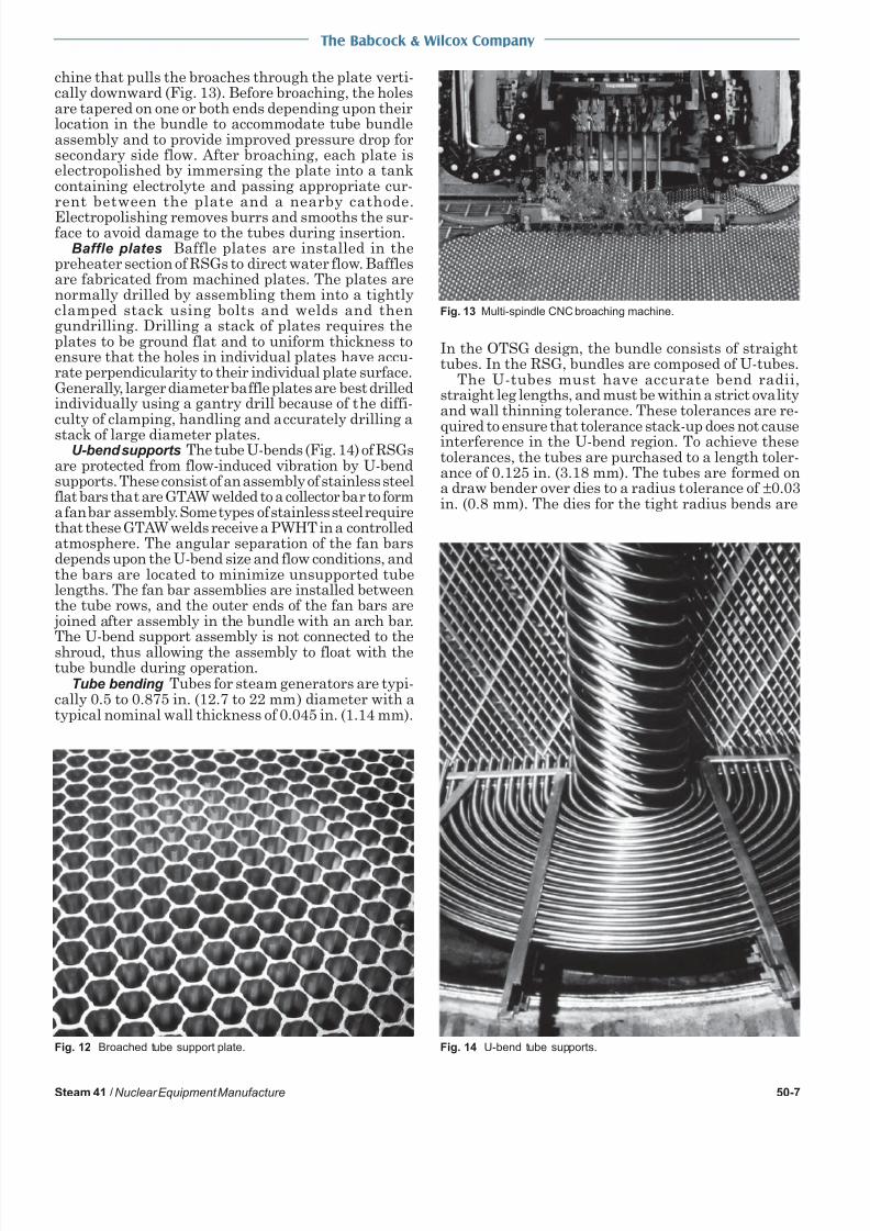
OTSGs use broached tube support plates (TSP) tosupport the bundle. These TSPs are typically flatplates made of stainless steel that are drilled to thetube bundle pattern using a multi-spindle drill. Each
hole is then machined by broaching so that the finahole shape resembles a trefoil pattern consisting ofthree contact areas that support the tube and threeenlarged areas that allow flow through the plate (Fig12). Broaching is done on a multi-spindle CNC ma-
Fig. 10 Radiographic examination of a steam generator weld.
Fig. 11 Lattice-grid tube supports.
8/13/2019 Nuclear equipment manufacture.pdf
http://slidepdf.com/reader/full/nuclear-equipment-manufacturepdf 7/14
The Babcock & Wilcox Company
Steam 41 /Nuclear Equipment Manufacture 50-7
chine that pulls the broaches through the plate verti-cally downward (Fig. 13). Before broaching, the holesare tapered on one or both ends depending upon theirlocation in the bundle to accommodate tube bundleassembly and to provide improved pressure drop forsecondary side flow. After broaching, each plate iselectropolished by immersing the plate into a tankcontaining electrolyte and passing appropriate cur-rent between the plate and a nearby cathode.
Electropolishing removes burrs and smooths the sur-face to avoid damage to the tubes during insertion.
Baffle plates Baffle plates are installed in thepreheater section of RSGs to direct water flow. Bafflesare fabricated from machined plates. The plates arenormally drilled by assembling them into a tightlyclamped stack using bolts and welds and thengundrilling. Drilling a stack of plates requires theplates to be ground flat and to uniform thickness toensure that the holes in individual plates have accu-rate perpendicularity to their individual plate surface.Generally, larger diameter baffle plates are best drilledindividually using a gantry drill because of the diffi-culty of clamping, handling and accurately drilling a
stack of large diameter plates.U-bend supports The tube U-bends (Fig. 14) of RSGs
are protected from flow-induced vibration by U-bendsupports. These consist of an assembly of stainless steelflat bars that are GTAW welded to a collector bar to forma fan bar assembly. Some types of stainless steel requirethat these GTAW welds receive a PWHT in a controlledatmosphere. The angular separation of the fan barsdepends upon the U-bend size and flow conditions, andthe bars are located to minimize unsupported tubelengths. The fan bar assemblies are installed betweenthe tube rows, and the outer ends of the fan bars are
joined after assembly in the bundle with an arch bar.The U-bend support assembly is not connected to theshroud, thus allowing the assembly to float with thetube bundle during operation.
Tube bending Tubes for steam generators are typi-cally 0.5 to 0.875 in. (12.7 to 22 mm) diameter with atypical nominal wall thickness of 0.045 in. (1.14 mm).
In the OTSG design, the bundle consists of straighttubes. In the RSG, bundles are composed of U-tubes.
The U-tubes must have accurate bend radii,straight leg lengths, and must be within a strict ovalityand wall thinning tolerance. These tolerances are re-
quired to ensure that tolerance stack-up does not causeinterference in the U-bend region. To achieve thesetolerances, the tubes are purchased to a length toler-ance of 0.125 in. (3.18 mm). The tubes are formed ona draw bender over dies to a radius tolerance of ±0.03in. (0.8 mm). The dies for the tight radius bends are
Fig. 13 Multi-spindle CNC broaching machine.
Fig. 12 Broached tube support plate. Fig. 14 U-bend tube supports.

8/13/2019 Nuclear equipment manufacture.pdf
http://slidepdf.com/reader/full/nuclear-equipment-manufacturepdf 8/14
The Babcock & Wilcox Company
50-8 Steam 41 /Nuclear Equipment Manufacture
designed to contain the tube and to minimize ovalityduring bending. After the tubes are bent, they aredimensionally checked to verify that all toleranceshave been met.
Shrouds The shrouds are fabricated from steelplates rolled into cylinders and their longitudinalseams are joined by SAW. The sections of the shroudnear the preheater section of the RSG may have theirinside diameters machined round. This ensures that
baffle plates can slide axially and can expand duringvarious operating conditions. These shroud sectionsfor RSGs may also contain manifolds to distribute theincoming feedwater and recirculating water.
It is critical to ensure that the inside radius of theshroud is accurate so that the required clearance existsto allow lattice grids and baffles to be aligned with thetubesheet pattern. The inside radius of the RSG shroudis measured by projecting a laser down its centerline andusing a radial micrometer. Alternatively, an optical in-strument can be used in a similar setup.
Tube bundle assembly
The tube bundle is assembled in a clean room (Fig.
15) to ensure that the components are not contami-nated. Cleanliness and material control procedures arecarefully monitored. All internal components arecleaned just prior to enclosing them.
Installation of shroud and bundle supports The shroudmust be installed and aligned to ensure that the tubebundle supports can be aligned with the tubesheet drill-ing pattern. The shroud is installed horizontally byusing wheels or bearing rollers bolted onto one end. Thisallows the tubesheet end of the shroud to roll into theshell as a crane supports the other end and provides ahorizontal push. The shroud is then aligned using pinslocated around its circumference.
If the RSG design includes an integral preheater,a secondary divider plate is installed with a poweredcart, which also adjusts the position of the dividerplate. This plate fits into grooves in the shroud. Thepreheater baffle plates are then installed by mount-ing them on the end of a boom that is driven by a floormounted power unit. The holes in the baffle platesmust be aligned with those in the tubesheet.
Baffle plates are supported by tie rods machined to
length that ensure parallel placement of the plates tothe tubesheet. The baffle plates must have radialclearance to allow for thermal expansion. This clearance, however, creates an installation problem because the baffles must support the tube bundle andremain in alignment with the tubesheet while thetubes are being installed. This problem is overcome byinstalling a special shim that fits into the clearancebetween the baffle plates and the shroud. This shim
dissolves during vessel operation, thereby maintain-ing the proper clearance.
The lattice grids for RSGs are installed by mounting them on a boom (Fig. 16). The grids are alignedwith the tubesheet using optical scopes mounted onthe primary side of the tubesheet. A small target is po-sitioned in selected tube locations on the lattice gridsand the grid is adjusted using wedges around its circumference until the target aligns with the scope’s lineof sight. Alignment rods that are the same diameteras the tube are also used to check the alignment ofthe lattice grids. The grids are held in place by sup-port blocks welded to the inside of the shroud.
To ensure that the tubes can be installed in an
OTSG without misalignment or damage to their sur-face, it is critical that the TSPs are aligned with thehole pattern in the tubesheet and are parallel to thetubesheet face. The TSPs for OTSGs are connectedtogether with tie rods. The first set of tie rods is in-stalled into the tubesheet, and the ends are checkedwith a coordinate measuring machine to ensure theyprovide a flat plane for the first TSP to rest againstSupport blocks are aligned and welded to the shroudproviding support to the circumferential edge of theTSP. The first support plate is installed and alignedusing similar optical techniques to that used for aligning lattice grids. Then, wedges and keys are installedto firmly support the TSP and to keep it in alignmentduring rotation of the vessel for subsequent manufacturing operations. This sequence is repeated for eachTSP. After all the TSPs are installed, the top tubesheetis set up on an alignment fixture in preparation forinstallation. Optical alignment scopes are set up, andthe tubesheet is fit to the cylindrical shell. Ceramicbacking bar is installed to the inside diameter of thecircumferential seam along with alignment wedges
Fig. 15 Nuclear clean room. Fig. 16 Installation of lattice grid tube bundle support.

8/13/2019 Nuclear equipment manufacture.pdf
http://slidepdf.com/reader/full/nuclear-equipment-manufacturepdf 9/14
The Babcock & Wilcox Company
Steam 41 /Nuclear Equipment Manufacture 50-9
After fitup and alignment have been confirmed, the rootpasses of the weld are made while monitoring the align-ment. The ceramic backing bar is removed, the opticalinstruments are removed, and the remainder of theweld is completed with SAW. The completed seam thenreceives MT, UT (Fig. 17) and RT.
Installation of tubes Tubes are installed with thevessel in a horizontal position. Each tube hole andtube are dry-swabbed clean just prior to assembly.
Cleaning operations at this stage are done withoutliquids. Any moisture or contaminants trapped be-tween the tube and tube hole can cause tube-to-tubesheet welding defects.
In an RSG, the U-tubes are fitted with a plastic tubeend pointer and installed in layers from the smallestbend radius tubes to the largest bend radius tubes(Fig. 18) starting with the lowest layer. This tubingsequence simplifies the temporary supports that mustbe installed to keep the U-bend supported during tubeinstallation. As each layer is installed, the appropri-ate U-bend support fan is installed. The partially com-pleted bundle is temporarily supported to prevent sag-ging due to the weight of the tubes. Each U-tube is
inserted until it protrudes the specified amount fromthe primary face of the tubesheet. This amount of protrusion depends upon whether the tube-to-tubesheet weld is a fillet weld or a flush weld. Theinstaller also checks for proper clearance between eachU-bend. The tubes are tack expanded by inserting anexpander inside the tubes about 0.75 in. (19 mm). Theexpander consists of a split collet actuated by a hy-draulically driven tapered mandrel. This yields thetube sufficiently to hold it in place and to close the gapfor welding. This expansion method produces less re-sidual stress in the tube than other methods, such asroller expansion.
In an OTSG, the straight tubes are fitted with plas-tic tube end pointers, cleaned, and installed in layersstarting from the top layer and working down. Thistubing sequence avoids any particulate matter thatmay be picked up by the tube during insertion fromfalling down onto tube ends that have already beeninstalled. This sequence also simplifies retrieval of atube end pointer in the unlikely event that one comesloose during tube insertion. Tubes are insertedthrough the bottom tubesheet, through the TSP as-sembly, and through the upper tubesheet. The tubesare inserted so that the correct tube projection isachieved at the upper tubesheet. The tubes are thentack expanded using the same tack expansion tech-niques that are used for RSGs. The tubes in the up-per tubesheet are final tack expanded and seal welded.The tube ends in the lower tubesheet receive an ini-tial expansion to provide some support to the tubewhile the tube ends are machined to the proper pro-trusion at the lower tubesheet. This is followed by afinal tack expansion.
Tube-to-tubesheet welding The tubes and tube-sheets are joined with automatic gas tungsten arcwelding (GTAW). The tube-to-tubesheet weldingheads are specially designed units to provide welds of consistent quality (Fig. 19). At the beginning of eachshift, each operator makes a tube-to-tubesheet weld test
Fig. 17 Ultrasonic inspection of seam weld.
Fig. 18 Installation of tubing.

8/13/2019 Nuclear equipment manufacture.pdf
http://slidepdf.com/reader/full/nuclear-equipment-manufacturepdf 10/14
The Babcock & Wilcox Company
50-10 Steam 41 /Nuclear Equipment Manufacture
block. The block receives a visual and PT inspection, andis then sectioned for further metallurgical examination.
Each weld is visually compared to a workmanshipsample. All welds not meeting the sample quality arerepaired and then rewelded. This is followed by PTexamination of all tube-to-tubesheet welds. Finally, aleak test is done by pressurizing the secondary side witha mixture of air and helium. The primary tubesheet faceis then monitored for helium leaks at the welds.
Tube expansion Each tube is hydraulically ex-panded into its hole after tube-to-tubesheet welding.This expansion closes the crevice between the tube andthe hole to avoid a potential corrosion site. The tubemay be expanded near the secondary face of thetubesheet or it may be expanded full depth or at theprimary face depending on customer specifications.Hydraulic expansion is the recommended method fornuclear steam generators because it produces less re-sidual stress in the tube and reduces the potential forstress corrosion cracking compared to other expansionmethods. Each tube is expanded by inserting a probethat has a seal positioned at each end of the expansionzone. Distilled water at approximately 35,000 psi (241.3
MPa) is pumped through the probe, expanding thetube and sealing it against the tube hole.
The expansion probe must be carefully positionedwith respect to the secondary face of the tubesheet. If the probe is positioned beyond the face, then unac-ceptable tube deformation could occur. If the probe istoo far inside the tube hole, an unacceptably long crev-ice could possibly result. Therefore, the tubesheetthickness variation is measured and the probe lengthis adjusted to ensure proper positioning.
Tubes located near the tubesheet periphery mayrequire expansion using special probes because thecurvature of the head encroaches on the probe inser-tion area. A flexible extension is attached to the probe,which allows it to be inserted in confined areas. Incases where the tube must be expanded full depth, the
expansion is done in two or more steps. Following expansion, each tube is examined with eddy currenttesting (ECT) techniques.
Steam drum internals
RSGs require a steam drum and steam separatorsto remove moisture from the steam (Fig. 20). OTSGsprovide steam at slightly superheated conditions anddo not require steam separators. The steam separa-
tors are similar in design to those used on fossil-fuelboilers. Generally, the separators in nuclear steamgenerators are an axial flow type, although tangen-tial flow separators have been used. There are typi-cally more than 100 separators in a large RSG. Mostdesigns also have smaller secondary separators located above the primary units.
The fabrication and assembly tolerances of steamseparators are critical. The shape and assembly clearances of internal components have a significant effecton separator performance. Custom made assembly
jigs and fixtures are used to ensure that the requiredtolerances are met. In addition, all internal welds arecarefully ground to avoid discontinuities that affect
separator performance.The steam separators are installed in a deck struc
ture made of steel plate. This deck support structureis welded to the inside of the drum, and the supportsare designed to accommodate differential thermal expansion during steam generator operation as well asloads due to specified accidental pipe break and seismic events. The separator and deck structure is usually of modular construction to simplify installationinto the steam drum.
Final assembly
Closing seam fitting and welding of RSGs The finaassembly operation for RSG fabrication consists of fit-ting and welding the closing seam, which is usuallyone of the circumferential seams on the cone. Thesteam drum and the cylindrical shell are positionedon rotators and the circumferential seam is alignedPrevious machining of the component mating surfacesassures good alignment. The weld could be either atwo-sided weld if there is sufficient access to the in-side of the vessel, or a one-sided weld. If a one-sidedweld is used, it is generally of a narrow groove designto limit the volume of weld deposit. The sequence ofmaking a one-sided weld is described later.
Prior to starting work on the inside of the vessel,the tube bundle and the steam separator assembly aresealed off to prevent weld flux and other material fromentering. The drum and cylindrical shell are alignedand the seam is tack welded to hold the componentsin position. The next several weld passes are completed using shielded metal arc welding (SMAW). Thisadditional welding provides enough structurastrength to allow the assembly to be moved to a sub-merged arc welding station where the outside of theweld is finished using SAW. As the vessel is rotatedthe weld is completed.
Due to access limitations at some sites installingreplacement RSGs, fitting and welding of the closingseam may not occur until after the RSG is inside theFig. 19 Tube-to-tubesheet welding.

8/13/2019 Nuclear equipment manufacture.pdf
http://slidepdf.com/reader/full/nuclear-equipment-manufacturepdf 11/14
The Babcock & Wilcox Company
Steam 41 /Nuclear Equipment Manufacture 50-11
containment building. In these cases, the lower half of the steam generator is generally assembled to therefitted upper half of the original steam generator.Typically, the steam drum and head will be refit withnew separators and steam flow control equipment
before the closing seam is made with the steam gen-erator vertical and in place.
Local PWHT of RSG closing seam The closing cir-cumferential seam requires post weld heat treatment.Because temperature differences during this procedurecan exceed those experienced during normal opera-tion of the vessel, care must be taken to avoid exces-sive and harmful differential expansion of internalcomponents. Temperatures can be controlled using anelectric furnace designed to fit around the closingseam. Insulation is applied to the outside of the ves-sel shell and to the attachments in the vicinity of theseam. The tube bundle U-bend region is also insulatedto reduce radiant heat transfer. Internal heat trans-fer is further reduced by drawing a vacuum on thesecondary side of the vessel. During PWHT, air maybe blown through the tube bundle primary side to limittube temperature. Thermocouples are mounted ineach critical area to monitor and control the process.
The electric furnace has several zones that can beindependently controlled to keep the temperatureswithin prescribed limits. A computer is used to controlthe furnace and to collect data and provide a recordof temperatures.
Final assembly and local PWHT of OTSG pressureboundary After the straight tubes are inserted throughthe lower tubesheet, seal welded and helium leaktested, the lower primary head is installed. The cir-cumferential seam between the lower primary headand lower tubesheet requires local PWHT after weld-ing. This operation is complex because the tube bundlewill be partially heated during the operation. Tem-perature gradient limits are imposed to limit thestresses in each component and to limit the loads onthe tubes due to the difference in coefficient of ther-mal expansion between the tubes and carbon steelpressure boundary. An electrically heated clamshellfurnace is installed around each circumferential weldseam. Supplementary electric heaters may be placedon other components such as the tubesheet primary
face to further control the temperature gradients.Heat transfer by convection to the secondary side maybe controlled either by drawing a vacuum, or by pro-viding air circulation, depending on the requirementsduring heat-up or cool-down.
Final inspection and testing
A hydrostatic test is done on the completed vessel;the primary and secondary sides are tested separately.
The test consists of filling the vessel with treated wa-ter that is pressurized to 125% of the design pressure.The pressure is reduced and held at the design pres-sure while an inspector examines the vessel for leaks.The metal temperature must be held above 70F (21C)to keep it well above its brittle transition temperature.
After hydrostatic testing, the vessel is drained anddried. A vacuum is drawn on the secondary side to as-sist drying. Felt plugs are also blown through thetubes to dry them. All accessible pressure boundarywelds are then examined by the MT method.
Nozzles and integral support surfaces, called ter-minal points, connect to mating components in thefield and must be within specified tolerances to sim-
plify field installation and minimize stresses causedby fitup. Special coordinate measuring machines (Fig.21) are used to set up the tools used to machine thefinal terminal point geometry (Fig. 22). It is commonpractice to finish machine nozzle weld preps at thisstage to bring them within tolerance.
Just prior to closing the vessel, the insides of thetubes are cleaned by blowing felt plugs through them.The secondary side of the steam generator is exam-ined and cleaned, and final drum internal componentsare installed. All manway covers are bolted on. Theprimary and secondary sides of the vessel are evacu-ated and backfilled with nitrogen to reduce the for-mation of oxides. Steam generators are wrapped inshrink-wrap plastic to protect them during shipment.
Surface conditioning
Some steam generator owners specify that the in-side surfaces of the primary side (excluding the tub-ing) are to be surface conditioned or electropolished.This process produces a very smooth surface finish,
Fig. 20 Fabrication of steam separator subassembly.
Fig. 21 Set up of nozzle machining tools using coordinated mea-suring machine.

8/13/2019 Nuclear equipment manufacture.pdf
http://slidepdf.com/reader/full/nuclear-equipment-manufacturepdf 12/14
The Babcock & Wilcox Company
50-12 Steam 41 /Nuclear Equipment Manufacture
typically 10 microinches or better. This results in a sig-
nificant reduction in true surface area of the workpiece which in turn reduces radioactive isotope updateand occupational exposure. Reduced occupational ex-posure makes these components more easily main-tained in the field.
The first step in surface conditioning is to grind thesurface with abrasive flap wheels. Several passes arerequired, each one made with progressively finer abra-sives until a surface finish of 40 microinches isachieved. This operation can be done by machine onan individual component prior to assembly. However,this is usually impractical because the componentmust then be protected from surface damage for theremainder of the manufacturing operation. Usually,
the grinding is done near the end of the assembly se-quence with hand tools. This is a time consuming op-eration, especially if as-welded surfaces are involved.
The second step in surface conditioning is to impartfurther improvements in surface roughness on a mi-croscopic scale by electropolishing. In electropolishing,an applied electric current flows from the metal sur-face (anode or work piece) through a conductive elec-trolytic solution to another conducting surface (cath-ode). This process smooths the micropeaks formed bymechanical grinding.
Shipping
Steam generators may be shipped by rail or by spe-
cial road transport directly to the plant site, or maytravel part of the way by barge or heavy lift ship. Forrail transportation, the load must be centered on thecar for even weight distribution. If the vessel is long,it can span two railway cars. If it is short, a singleheavy-duty flat car is usually sufficient (Fig. 23). Thevessel is oriented to minimize its width and height andis loaded onto bunks fastened to the car. Loads up to16 ft (4.9 m) in diameter can be shipped along mostroutes in the United States and Canada. Shippinglarger units requires measurement of bridge clearancesand other potential obstructions. If the vessel spans two
cars, the bunks must be designed to allow movement ofthe load while negotiating curves. Additional ballast maybe attached to the rail car to lower the center of gravity.
Manufacture of pressurizers
Pressurizers are cylindrical vessels that help stabilize the pressure in the primary heat transport sys-tem. (See Chapter 46.) Each unit is fitted with special
penetrations in which electrical heaters are installed.
Pressure boundary assembly
The pressure boundary consists of cylindrical shellsand hemispherical heads. The pressure boundary con-tains a surge nozzle, spray inlet nozzle, several connections for electric heaters, and various small water levelnozzles. The manufacturing methods and quality assurance requirements for these components are the sameas those described previously for steam generators.
Heater connections and installation The heaters arethe direct immersion type, sheathed in stainless steelor Inconel and assembled in bundles. In some designsthe heaters consist of a single straight element. Each
of the elements is field assembled through penetrationsin the vessel wall and is sealed by means of a bolted closure. The closure is sealed by gaskets or patented me-chanical seals. An electrical connection is then made tothe end of each heater using a special insulated fitting
Post weld heat treatment
PWHT of pressurizers is simpler than that of steamgenerators because there are no complex geometriesor internals that limit heating and cooling ratesPWHT is done by putting the completed pressurizerin a gas furnace and heating to 1125F (607C).
Some patented mechanical seals used for the heaterconnections must be installed prior to PWHT becauseof their required machined surface finish. This machining can not be done after the component is welded ontothe vessel because of inadequate access for specializedequipment. As a result, the sealing surface is protectedfrom the furnace environment by coating it with anantiscaling compound. Some minor surface dressing ofthe sealing surface may be required after PWHT.
Fig. 22 Final nozzle end machining.
Fig. 23 Steam generator awaiting offloading to heavy lift ship.

8/13/2019 Nuclear equipment manufacture.pdf
http://slidepdf.com/reader/full/nuclear-equipment-manufacturepdf 13/14
The Babcock & Wilcox Company
Steam 41 /Nuclear Equipment Manufacture 50-13
Manufacture of dry shielded canisters1
Dry shielded canisters are part of a system of con-tainers used to store and ship spent nuclear fuel. Thecanisters are designed to safely store bundles of spentfuel at plant sites, and some designs allow transportto long-term storage sites. The design of the canistersand internal structures serves as the containmentboundary to confine radioactive spent fuel and pro-
vide a leak-tight, inert atmosphere to ensure that theintegrity of the fuel cladding is maintained. A typicalcanister consists of an outer cylindrical shell made of stainless steel, typically 5.5 ft (1.7 m) in diameter by15.5 ft (4.7 m) in length. The internal assembly con-sists of an array of guide sleeves that are square incross-section. Each one is designed to accept a bundleof spent fuel. The guide sleeves are made of stainlesssteel. The ends of the canisters are capped with shieldplugs that include lead shielding. Although many in-dividualized components are similar to other nuclearpressure vessels, there are several unique featuresthat require specialized manufacturing operations.For example, for some designs, it is necessary to limit the
canister weight due to specific lifting capabilities at theplant site. Therefore, material thickness must be checkedfrequently to allow the manufacturing tolerances to beworked toward their minimum material condition.
The cylindrical shells are made from stainless steelplate using manufacturing operations common toother components described earlier. However, theiroutside surface must meet tight tolerances on circu-larity, diameter and straightness because the cylindermust fit inside a shielded storage container. The mini-mum diameter is limited by the requirement to insertthe basket assembly into the cylinder without restric-tion. The diameter must also provide sufficient allow-ance for differential expansion of shell and basketassembly components when the assembly is subject toelevated temperature during service.
The shield plugs consist of a stainless or carbon steelcircular disk with ribs or stiffeners welded to it. Theentire shield plug assembly is poured full of lead typi-
cally 5 in. (127 mm) thick. A gamma ray scan confirmsthe effective thickness of the lead shielding.
The top cover plates are welded to the canister inthe field. Consequently, it is critical to maintain a spe-cific radial gap between the cover plate and the in-side diameter (ID) of the cylinder. One way of accom-plishing this is by machining and hand working theOD of the cover plates to suit the as-built ID of thecylinder. The cover plate must also meet a specific
thickness tolerance to ensure that the maximumamount of fuel can physically fit into the canister. Thisrequires flattening operations of the plates during ma-chining and frequent UT thickness checks. There aresimilar requirements to custom machine, flatten andhand work the top shield plug to achieve specifiedradial gap.
The guide sleeves are made to form a square cross-section and are sized to suit the dimensions of PWRand BWR fuel assemblies. The tight tolerances on theguide sleeves ensure that a spent fuel bundle can beinserted without binding. The guide sleeves are formedfrom stainless steel sheet, and the longitudinal seamsare welded using a welding jig that maintains the
sleeve geometry. The welding equipment utilizes cool-ing methods and heat input techniques that minimizedistortion due to welding.
During manufacture and assembly of the basket as-sembly, it is critical to align the spacer discs that sup-port the guide sleeve so the sleeves can be installedwithout distortion or binding. The spacer discs are setup in an alignment jig and welded to the support rods.The entire assembly must meet exacting geometricrequirements of overall perpendicularity, cylindricityand height to accommodate thermal expansion dur-ing service and to resist potential impact loading dur-ing transport.
After the basket assembly is assembled into the cyl-inder, the final alignment of each guide sleeve ischecked using a plug gauge. The plug gauge, repre-senting the maximum size of fuel to be stored in thecanister, must pass through the guide sleeve within aspecified load limit.
Inconel is a trademark of the Special Metals Corporation group of companies.
1. Johnson, E.R., and Saverot, P.M., Eds., Monographon Spent Nuclear Fuel Storage Technologies, Instituteof Nuclear Materials Management, Northbrook, Illinois,1997.
Reference

8/13/2019 Nuclear equipment manufacture.pdf
http://slidepdf.com/reader/full/nuclear-equipment-manufacturepdf 14/14
The Babcock & Wilcox Company
B&W nuclear steam generator U-bend supports provide close-tolerance fit for improved vibration control.