number: 550 - iapmoes.org · overview: the technical information contained within this evaluation...
TRANSCRIPT

Number: 550
Originally Issued: 01/31/2018 Revised: 02/15/2018 Valid Through: 01/31/2019
Page 1 of 161
ASC PROFILES LLC AEP SPAN AND ASC BUILDING PRODUCTS: SINGLE SKIN STEEL ROOF AND WALL PANELS WITH EXPOSED FASTENERS CSI Section: 07 61 00 Sheet Metal Roofing 07 64 00 Sheet Metal Wall Cladding 1.0 RECOGNITION ASC Profiles LLC Single Skin Steel Roof and Wall Panels with Exposed Fasteners have been evaluated for use as exterior roof and wall covering panels. The structural and fire-resistance properties of the panels have been evaluated for compliance with the following codes:
• 2015, 2012, and 2009 International Building Code® (IBC)
• 2015, 2012, and 2009 International Residential Code® (IRC)
• 2016 and 2013 California Building Code® (CBC) –Attached supplement
2.0 LIMITATIONS
Use of the ASC Profiles LLC Single Skin Steel Roof and Wall Panels and fasteners recognized in this report is subject to the following limitations: 2.1 Metal panels used in roof applications shall be applied to a solid or closely fitted deck, except where the roof covering is specifically designed to be applied to spaced support members. The panel installation tables in this report provide applicable substrate limitations. 2.2 Calculations demonstrating compliance with this report shall be submitted to the code official for approval. The calculations shall be prepared by a registered design professional where required by the statutes of the jurisdiction in which the project is to be constructed. 2.3 Recommended slopes are defined within the OVERVIEW portion of this report. The minimum roof panel slopes shall conform to IBC Section 1507.4.2 or IRC Section R905.10.2, or as stated in this report. 2.4 Roof panel flashing requirements, when applicable, shall comply with IBC Section 1503.2 and 1503.3, or IRC Sections R903.2 and R903.3. Underlayment, including installation, shall comply with IBC Section 1507.4.5 or IRC Section R905.10.5, with consideration of applicable wind conditions.
2.5 Panels used on exterior walls shall be used with a water-resistant barrier complying and installed in accordance with IBC Section 1403.2 or IRC Section R703.1, and flashing complying with IBC Section 1405.4 or IRC Section R703.4 to provide an exterior wall envelope. Vapor retarders shall be installed, as applicable, in accordance with IBC Section 1405.3 or IRC Section R702.7. 2.6 Design of panel penetrations and other panel discontinuities shall be the responsibility of the structural design professional in accordance with IBC Section 1604.4, or in accordance with the manufacturer’s installation instructions, when approved by the building official.
2.7 Where panels are used as vertical diaphragm shear resistance in walls (shear wall) of light-frame construction, the walls shall be classified as a “bearing wall system” or “building frame system” with “light-framed walls with shear panels of all other materials” subject to the conditions of this classification as defined in ASCE/SEI 7, Section 12.2.
2.8 Product Performance: 2.8.1 Structural: The tables provided in this report specify the gross and effective section properties, inward (positive) uniform allowable loads, allowable reactions at supports, outward (negative) uniform allowable loads, and diaphragm shear capacities, q (plf) and flexibility factors, F (10-6 in/lbs) for each of the panels described in Section 4.1 of this report. 2.8.2 Roof Classification: Roof assemblies complying with the requirements of IBC Section 1505.2, Exception 2, or IRC Section R902.1, Exception 2, are considered Class A roof assemblies. For other conditions, roof assemblies shall be listed as Class A, B, or C in accordance with ASTM E108 or UL 790, by an approved listing agency or shall be considered as a non-classified roofing. ASC Profiles shall be contacted for information on specific listed assemblies.
2.8.3 Wall Assembly Fire-Resistance: Wall panels are limited to installations where non-fire-resistance-rated construction is permitted by the IBC or IRC. Wall panels may be permitted in fire-resistance-rated wall assemblies based on successful testing in accordance with the requirements prescribed in IBC Section 703. 2.8.4 Air and Water Infiltration: Air and water infiltration resistance is outside the scope of this report. Weather protection shall comply with Sections 2.4 and 2.5 of this report.
2.8.5 Hail Resistance: Hail resistance is outside the scope of this report.
The product described in this Uniform Evaluation Service (UES) Report has been evaluated as an alternative material, design or method of construction in order to satisfy and comply with the intent of the provision of the code, as noted in this report, and for at least equivalence to that prescribed in the code in quality, strength, effectiveness, fire resistance, durability and safely, as applicable, in accordance with IBC Section 104.11. This document shall only be reproduced in its entirety.
Copyright © 2018 by International Association of Plumbing and Mechanical Officials. All rights reserved. Printed in the United States. Ph: 1-877-4IESRPT • Fax: 909.472.4171 web: www.uniform-es.org • 4755 East Philadelphia Street, Ontario, California 91761-2816 – USA Page 1 of 161

Number: 550
Originally Issued: 01/31/2018 Revised: 02/15/2018 Valid Through: 01/31/2019
Page 2 of 161
2.8.6 Wind-blown Debris Resistance: Wind-blown debris resistance is outside the scope of this report. 3.0 PRODUCT USE General Design and Installation shall be in accordance with the referenced codes in Section 1.0 of this report, the information provided in this report, ASC Profile’s product installation guides. Where conflicts occur, the more restrictive shall govern. 4.0 PRODUCT DESCRIPTION 4.1 Panels: The panels are available in various configurations as illustrated in the figures accompanying the tables in this report. Panels are either unpainted or are provided with a painted finish. Additional information on the panel configurations is provided in the OVERVIEW portion of this report.
The roof panels comply with requirements for metal roof panels in Chapter 15 of the IBC, and Section R905 of the IRC. The wall panels comply with requirements for steel wall coverings in Chapter 14 of the IBC, and Section R703 of the IRC. 4.2 Base Materials: All No. 18 and No. 20 gage panels are manufactured from sheet steel with G90 galvanized coatings conforming to ASTM A653 SS Grade 40. All No. 22 and No. 24 gage panels are manufactured from AZ50 aluminum-zinc alloy coated steel sheet conforming to ASTM A792 SS grade 50, or from G90 galvanized sheet per ASTM A653 SS grade 50. All No. 26 and No. 29 gage panels are manufactured from AZ50 aluminum-zinc alloy coated steel sheet conforming to ASTM A792 SS grade 80. The panels are also available prepainted in accordance with ASTM A755. 4.3 Fasteners: The fasteners size and type requirements are identified in the panel installation tables within this report. All fasteners shall be zinc-plated with an added corrosion resistant coating, or of a 300 series stainless steel construction. Self-tapping metal to metal fasteners shall comply with ASTM C1513. Fasteners installed into treated wood shall be 300 series stainless steel or designed specifically for use with treated wood. 4.4 Substrates: ASC Profiles roof and wall panels may be fastened to numerous substrates including, but not limited to, the following: • Cold formed steel in accordance with AISI S100 • Hot rolled steel in accordance with AISC 360 • Concrete in accordance with ACI 318
• Plywood and OSB in accordance with DOC PS-1 and DOC PS-2
• Dimensional lumber in accordance with ANSI/AWC NDS®
The panel installation tables within this report provide applicable substrate and fastening requirements. For other support conditions, structural calculations complying with the applicable code shall be submitted to the code official for approval. 5.0 IDENTIFICATION A permanent label or a die-stamp label bearing the name and address of the manufacturers, the model number, and this evaluation report number (Evaluation Report ER-550) identifies the products listed in this report. The identification labels also include the IAPMO Uniform Evaluation Service Mark of Conformity, and either one of the following Marks of Conformity may be used:
or
IAPMO UES ER-550 6.0 SUBSTANTIATING DATA Data submitted in conformance with IAPMO UES Evaluation Criteria Single Skin Steel Roof and Wall Panels, EC-011, revised June 2015. Any product testing is from laboratories in compliance with ISO/IEC 17025.
7.0 CONTACT INFORMATION
ASC Profiles LLC 2110 Enterprise Blvd. West Sacramento, CA 95691 (800) 733-4955 www.ascprofiles.com

Number: 550
Originally Issued: 01/31/2018 Revised: 02/15/2018 Valid Through: 01/31/2019
Page 3 of 161
8.0 STATEMENT OF RECOGNITION This evaluation report describes the results of research carried out by IAPMO Uniform Evaluation Service on ASC Profiles LLC Single Skin Steel Roof and Wall Panels with Exposed Fasteners to assess conformance to the codes and standards shown in Section 1.0 of this report and documents the product’s certification.
Brian Gerber, P.E., S.E. Vice President, Technical Operations
Uniform Evaluation Service
Richard Beck, P.E., CBO, MCP Vice President, Uniform Evaluation Service
GP Russ Chaney CEO, The IAPMO Group
For additional information about this evaluation report please visit
www.uniform-es.org or email at [email protected]

Number: 550
Originally Issued: 01/31/2018 Revised: 02/15/2018 Valid Through: 01/31/2019
Page 4 of 161
CONTENTS: OVERVIEW: ................................................................................................................................................................. 5
GENERAL NOTES: .................................................................................................................................................. 7
1.0: 2 1/2” Corrugated .............................................................................................................................................. 10
2.0: Box Rib ............................................................................................................................................................ 15
3.0: Reversed Box Rib ............................................................................................................................................ 31
4.0 Delta Rib ............................................................................................................................................................ 47
5.0 Delta Rib III ....................................................................................................................................................... 52
6.0 HR-36® ............................................................................................................................................................... 57
7.0 Reversed HR-36® ............................................................................................................................................... 73
8.0 Mini-V-Beam ..................................................................................................................................................... 89
9.0 Nor-Clad® ......................................................................................................................................................... 103
10.0 Nu-Wave® Corrugated ................................................................................................................................... 108
11.0 PBR ................................................................................................................................................................ 120
12.0 Strata Rib® ...................................................................................................................................................... 124
13.0 Super-Span® ................................................................................................................................................... 129
14.0 Reversed Super-Span® ................................................................................................................................... 138
15.0 U-Panel........................................................................................................................................................... 145
16.0 X-Span® / Alta Rib ......................................................................................................................................... 156

Number: 550
Originally Issued: 01/31/2018 Revised: 02/15/2018 Valid Through: 01/31/2019
Page 5 of 161
OVERVIEW: The technical information contained within this evaluation report will assist the user in selecting the appropriate AEP Span or ASC Building Products’ exposed fastener panels and associated panel attachments.
The report consists of the following product information:
• General report notes and considerations • Panel views / fastener attachment locations • Panel section properties • Reaction at supports (web crippling) capacities • Inward (positive/ gravity) load tables • Outward (negative/ uplift) load tables • Diaphragm shear capacities
Panels:
The following is a list of panels contained within this report along with application limitations:
Panel: Application: Coverage: Gage No.: Minimum Slope*:
2 ½" Corrugated Roof, Wall 21 1/3" roof, 24" wall 29, 26 3:12 Box Rib Wall 36" 29, 26, 24, 22, 20, 18 n/a Reversed Box Rib Roof, Wall 36" 29, 26, 24, 22, 20, 18 1:12 Delta Rib Roof, Wall 24" 29, 26 3:12 Delta Rib III Roof, Wall 36" 29, 26 3:12 HR-36® Roof, Wall 36" 29, 26, 24, 22, 20, 18 1:12 Reversed HR-36 Wall 36" 29, 26, 24, 22, 20, 18 n/a Mini-V-Beam Roof, Wall 32" 26, 24, 22, 20, 18 1:12 Nor-Clad® Roof, Wall 36" 29, 26 3:12 Nu-Wave® Corrugated Roof, Wall 32" roof, 34 2/3" wall 26, 24, 22, 20 3:12 PBR Roof, Wall 36" 26 1:12 Strata Rib Roof, Wall 36" 29, 26 3:12 Super-Span Roof, Wall 36" 26, 24, 22 1:12 Reversed Super-Span Wall 36" 26, 24, 22 n/a U-Panel Roof, Wall 36" 29, 26, 24, 22 3:12 X-Span (Alta Rib) Roof, Wall 36" 29, 26 1:12
* - ASC recommended minimum slopes. Minimum installed panel slopes shall not be less than those stated in IBC Section 1507.4.2 or IRC Section R905.10.2.

Number: 550
Originally Issued: 01/31/2018 Revised: 02/15/2018 Valid Through: 01/31/2019
Page 6 of 161
Fasteners:
Below is a summary of the fastener size and types specified within this report. Fastener size and type shall be compatible with the material type, thickness, and grade of the supporting members. Section 4.3 of this report provides additional fastener requirements. Hex washer head (HWH) fasteners are shown below. However, alternative fastener heads are acceptable. Fasteners require sealing washers for weather-tight applications.
#12 metal-to-metal fastener (self-drilling point shown)
#14 metal-to-wood fastener (milled point shown)
#9 metal-to-wood fastener (dimensional lumber only; self-piercing point shown)
Side Lap Screw (#12minimum, #14 most common)
To assist in the evaluation of panel shear resistance, fastener connection shear strengths have been provided in Table B of this report for #12 fasteners into steel supports. These capacities are based on AISI S100, Section E4.3 for fastener shear strength and shear strengths limited by tilting and bearing. The capacities listed within Table B of this report are used to determine edge (perimeter) fastening requirements for shear resistance. The general notes and shear and flexibility tables of this report provide further information.
Table B
ThicknessASD W/Ω
ASD W/Ω
ASD W/Ω
ASD W/Ω
ASD W/Ω
ASD W/Ω
16ga (.0590") min. 222 276 293 371 378 491
18ga (.0459") 222 276 293 371 378 416
20ga (.0354") 222 276 286 294 282 282
22ga (.0294") 219 242 227 213 213 213
16ga (.0590") min. 222 276 293 371 378 491
18ga (.0459") 222 276 291 319 306 288
20ga (.0354") 222 251 229 211 195 195
22ga (.0294") 203 199 167 148 148 148
Steel(Gr 50 min.)
Steel(Gr 33 min.)
#12 Fastener Connection Shear Strengths (lbs)
Substrate
567
737
737
624333 414 440 557
557
567
333 414 440
Material/ Grade
341 320
441
320
423414 429
LRFD φW
LRFD φW
LRFD φW
LRFD φW
LRFD φW
LRFD φW
Panel Gauge / Grade
423
29ga (.0139") Gr80
26ga (.0173") Gr80
24ga (.0232") Gr50
22ga (.0294") Gr50
20ga (.0354") Gr40
329
333
363
18ga (.0459") Gr40
320
333 414 440 557 567
317 293
305 299 251 222 222 222
293
333 414 437 479 459 432
333 377 344

Number: 550
Originally Issued: 01/31/2018 Revised: 02/15/2018 Valid Through: 01/31/2019
Page 7 of 161
GENERAL NOTES: The following are general notes and considerations for the various report sections:
Panel views, with common fastener locations:
1. Included are drawings of the exposed fastener panels with basic dimensions and common fastener locations. These fastener locations correspond to the panel structural capacities contained within this report.
Panel section properties:
1. Section properties are calculated based on the panel geometry and the provisions of the American Iron and Steel Institute’s North American Specification for the Design of Cold-Formed Steel Structural Members (AISI S100).
2. For calculating the deflection of a panel subject to uniform distributed loads, the hybrid moment of inertia is used and is equal to two times the effective moment of inertia plus the gross moment of inertia divided by three: (2Ie + Ig)/3.
Reaction at supports (web crippling) capacity:
1. The panel reaction at supports capacity is calculated in accordance with AISI S100, Section C3.4 for multi-web steel panels
supported by framing that supports a uniform distributed load. Where calculation in accordance to AISI S100 C3.4 is not possible, the performance is evaluated from web crippling testing complying with AISI S909. The panel end and interior reactions listed in the tables are for uniformly distributed out-of-plane loads applied to the panels.
2. The ASD allowable (Pn/Ω) and LRFD factored (φPn) reactions presented in the tables are in pounds per linear foot (plf) running axially along the support for a given panel bearing length on the support. This is based on the web crippling capacity of an individual web multiplied by the number of webs per linear foot.
3. Reaction capacities listed in tables are acceptable for use with bearing lengths greater than those listed.

Number: 550
Originally Issued: 01/31/2018 Revised: 02/15/2018 Valid Through: 01/31/2019
Page 8 of 161
Positive (inward/ gravity) load capacity:
1. For uniform inward loading conditions, the appropriate support spacing is identified by referring to the inward load tables
within this report. For conditions not defined by these tables, values are readily derived through standard engineering mechanics using the panel’s section properties.
2. The ASD allowable (W/Ω) and LRFD factored (φW) panel strengths and have been evaluated for bending, shear, and combined bending and shear.
3. The L/240, L/180, and L/120 values are based on allowable service load deflections.
4. Table values denoted by ‘- ‘indicate that capacities are limited by allowable panel strength, not deflection. In those instances, the panel strength limits are reached prior to the deflection limits (L/180, etc.) being reached.
Negative (outward/ uplift) load capacity:
1. Common panel attachment combinations and associated outward load capacities are provided within this report. Panel
system negative (outward) uniform load capacities are based on fastener pullout, pullover, fastener tension, panel outward bending strength, and IBC Section 1604.3.1 deflection limit of L/60 for formed metal sheet roofing and siding.
2. Using the project’s defined outward wind loads, the appropriate Panel System Negative (Outward) Uniform Load Capacity table shall be reviewed to select a panel attachment that equals or exceeds the project wind load requirements. Not all possible fastener and substrate combinations are listed within the report. Alternative combinations are acceptable (i.e. attaching a panel assembly with fasteners into a concrete substrate), subject to approval of the code official, provided an analysis is performed by a registered design professional based on the failure modes noted above.
3. Fastener capacities in steel are based on AISI S100. Fastener capacities in wood substrates are based on ANSI/AWC NDS with a combined adjustment factor of 1.6 (2.16 LRFD).
4. Although nominal fastener sizes are provided in the tables, the appropriate fastener thread and point type shall still be properly specified for the selected substrate.
5. The 1-inch minimum fastener penetration specified for the Douglas Fir-Larch values applies to the usable thread length and this minimum depth does not include the tapered portion of the fastener.

Number: 550
Originally Issued: 01/31/2018 Revised: 02/15/2018 Valid Through: 01/31/2019
Page 9 of 161
Shear and flexibility tables:
1. Shear capacity (lbs/lineal ft) and flexibility factors (10-6 in/lb) are presented in the tables. Product capacities are determined in accordance with the American Iron and Steel Institute’s North American Standard for the Design of Profiled Steel Diaphragm Panels (AISI S310). Values are based on seismic governed loading conditions (Ωd=2.50) and are therefore conservative for applications governed by wind loads (Ωd=2.35).
2. Perimeter (edge) fastener spacing parallel to panel ribs has not been included within performance tables. Maximum spacing for edge fasteners parallel to panel flutes is defined as:
Max. edge fastener spacing = shear capacity per fastener (lb) / shear demand (lb/ft)
The Fastener Connection Shear Strength performance table within this report to assist with the needed fastener capacity in the above equation.
3. Tabulated shear capacities apply to both roof and wall diaphragms.
4. Tables apply to panels installed over steel supports. Evaluation of shear and flexibility over wood framing is outside the scope of this report.
5. Capacities are based on panel gauge, span, support fastener size and type, support attachment pattern, side lap connection fastener and side lap fastener spacing. Capacities based on minimum #12 side lap and support screws.
6. Note: Perimeter (edge) fastener spacing parallel to panel ribs has not been included within performance tables. Maximum spacing for edge fasteners parallel to panel flutes is defined as:
Max. edge fastener spacing = shear capacity per fastener (lb) / shear demand (lb/ft)
The Fastener Connection Shear Strength performance table within this report may be referenced to assist with the needed fastener capacity in the above equation.
7. Interpolation of diaphragm shear strength and flexibility factor between adjacent spans or side seam spacing is permitted provided the higher value does not exceed the lower value by more than 50 percent.

Number: 550
Originally Issued: 01/31/2018 Revised: 02/15/2018 Valid Through: 01/31/2019
Page 10 of 161
1.0: 2 1/2” Corrugated Figure 1.1 - Basic Dimensions and Panel Attachment (2 1/2” Corrugated):
21.3/4 Pattern (roof/wall): 24/4 Pattern (wall):
Table 1.1 - Section Properties (2 1/2” Corrugated):
Area Moment of Inertia
Distance to N.A. from
Bottom
Positive Section
Modulus
Negative Section
Modulusw t Fy Fu Ag Ig yb Sg+ Sg-
psf in ksi ksi in2/ft in4/ft in in3/ft in3/ft29 0.67 0.0139 80 82 0.1960 0.0055 0.26 0.0217 0.021726 0.83 0.0173 80 82 0.2439 0.0070 0.26 0.0269 0.0269
Moment of Inertia
Distance to N.A. from
Bottom
Section Modulus
Moment of Inertia
Distance to N.A. from
Bottom
Section Modulus
Ae/ft Ie+ yb Se+ Ie- yb Se- I+ I-
in2 in4/ft in in3/ft in4/ft in in3/ft in4/ft in4/ft29 0.1021 0.0055 0.26 0.0209 0.0055 0.26 0.0209 0.0055 0.005526 0.1407 0.0070 0.26 0.0269 0.0070 0.26 0.0269 0.0070 0.0070
Gauge Weight Base Metal Thickness
Yield Strength
Tensile Strength
Gross Section Properties
Gauge
Effective Section Properties Uniform Load Only
Area
Positive Negative
Id = (2Ie+Ig)/3
Number: 550
Originally Issued: 01/31/2018 Revised: 02/15/2018 Valid Through: 01/31/2019
Page 11 of 161
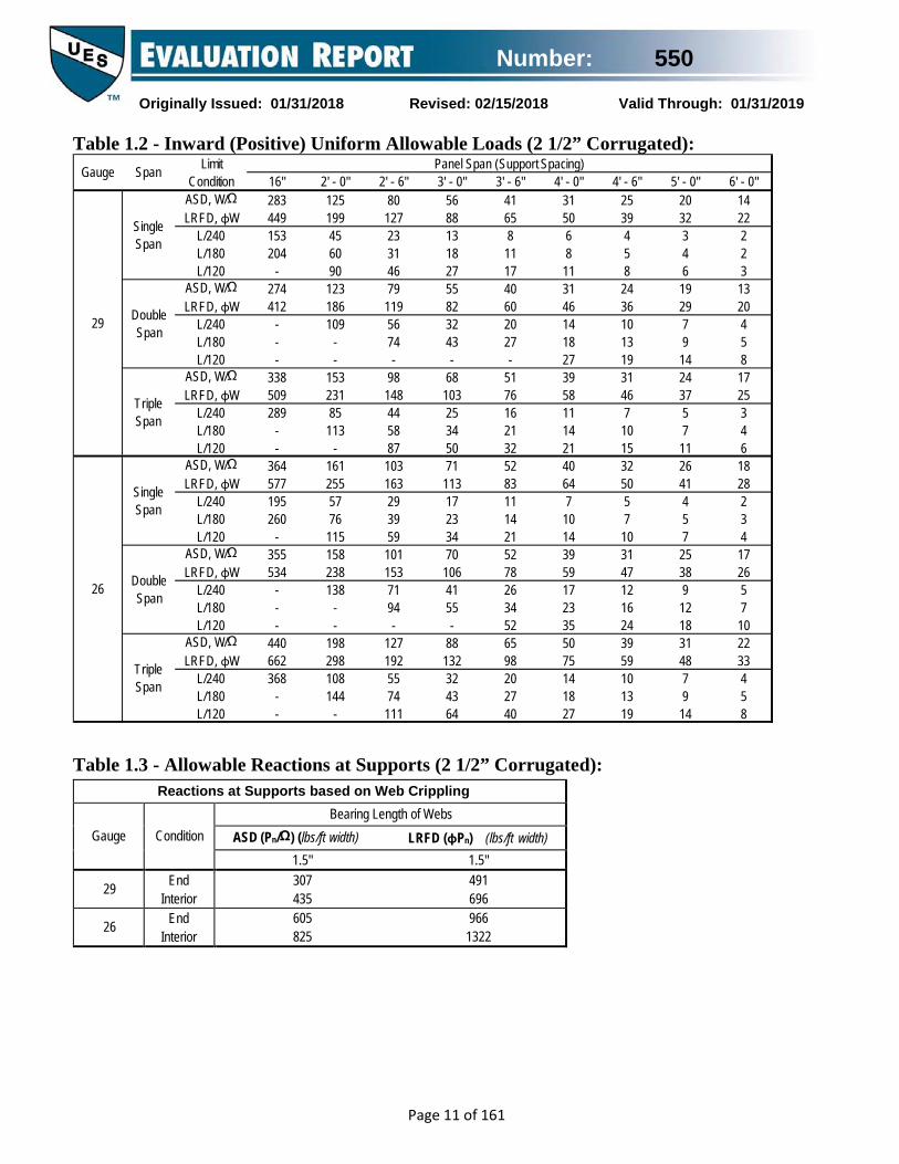
Table 1.2 - Inward (Positive) Uniform Allowable Loads (2 1/2” Corrugated):
Table 1.3 - Allowable Reactions at Supports (2 1/2” Corrugated):
16" 2' - 0" 2' - 6" 3' - 0" 3' - 6" 4' - 0" 4' - 6" 5' - 0" 6' - 0"ASD, W/Ω 283 125 80 56 41 31 25 20 14LRFD, φW 449 199 127 88 65 50 39 32 22
L/240 153 45 23 13 8 6 4 3 2L/180 204 60 31 18 11 8 5 4 2L/120 - 90 46 27 17 11 8 6 3
ASD, W/Ω 274 123 79 55 40 31 24 19 13LRFD, φW 412 186 119 82 60 46 36 29 20
L/240 - 109 56 32 20 14 10 7 4L/180 - - 74 43 27 18 13 9 5L/120 - - - - - 27 19 14 8
ASD, W/Ω 338 153 98 68 51 39 31 24 17LRFD, φW 509 231 148 103 76 58 46 37 25
L/240 289 85 44 25 16 11 7 5 3L/180 - 113 58 34 21 14 10 7 4L/120 - - 87 50 32 21 15 11 6
ASD, W/Ω 364 161 103 71 52 40 32 26 18LRFD, φW 577 255 163 113 83 64 50 41 28
L/240 195 57 29 17 11 7 5 4 2L/180 260 76 39 23 14 10 7 5 3L/120 - 115 59 34 21 14 10 7 4
ASD, W/Ω 355 158 101 70 52 39 31 25 17LRFD, φW 534 238 153 106 78 59 47 38 26
L/240 - 138 71 41 26 17 12 9 5L/180 - - 94 55 34 23 16 12 7L/120 - - - - 52 35 24 18 10
ASD, W/Ω 440 198 127 88 65 50 39 31 22LRFD, φW 662 298 192 132 98 75 59 48 33
L/240 368 108 55 32 20 14 10 7 4L/180 - 144 74 43 27 18 13 9 5L/120 - - 111 64 40 27 19 14 8
29
Single Span
Double Span
Triple Span
26
Single Span
Double Span
Triple Span
Gauge Span Limit Condition
Panel Span (Support Spacing)
Reactions at Supports based on Web Crippling
Gauge
Condition
Bearing Length of Webs ASD (Pn/Ω) (lbs/ft width) LRFD (φPn) (lbs/ft width)
1.5" 1.5"
29 End Interior
307 491 435 696
26 End Interior
605 966 825 1322

Number: 550
Originally Issued: 01/31/2018 Revised: 02/15/2018 Valid Through: 01/31/2019
Page 12 of 161
Table 1.4 - Outward (Negative) Uniform Allowable Loads (No. 29 gage 2 1/2” Corrugated):
Thick- ness
ASD W/Ω
ASD W/Ω
ASD W/Ω
ASD W/Ω
ASD W/Ω
ASD W/Ω
ASD W/Ω
ASD W/Ω
ASD W/Ω
#12 24/4 570 427 209 133 93 63 43 30 2221.3/4
#12 24/4 570 427 209 133 93 63 43 30 2221.3/4
#12 24/4 557 418 209 133 93 63 43 30 2221.3/4
#12 24/4 469 352 209 133 93 63 43 30 2221.3/4
#12 24/4 365 274 183 133 93 63 43 30 2221.3/4
#12 24/4 282 211 141 113 93 63 43 30 2221.3/4
#12 24/4 234 175 117 94 78 63 43 30 2221.3/4
#12 24/4 570 427 209 133 93 63 43 30 2221.3/4
#12 24/4 570 427 209 133 93 63 43 30 2221.3/4
#12 24/4 386 289 193 133 93 63 43 30 2221.3/4
#12 24/4 325 244 162 130 93 63 43 30 2221.3/4
#12 24/4 253 190 126 101 84 63 43 30 2221.3/4
#12 24/4 195 146 97 78 65 56 43 30 2221.3/4
#12 24/4 162 121 81 65 54 46 40 30 2221.3/4
#14 24/4 209 157 105 84 70 60 43 30 2221.3/4
#14 24/4 265 199 133 106 88 63 43 30 2221.3/4
#14 24/4 321 241 161 128 93 63 43 30 2221.3/4
#9 24/4 388 291 194 133 93 63 43 30 2221.3/4
#14 24/4 530 397 209 133 93 63 43 30 2221.3/4
30 22715 537 331 174 101 63
19/32"
23/32"
43
30 22523 392 262 174 101 63 43
30 22434 325 217 173 101 63 43
30 22358 269 179 143 101 63 43
2215/32" 283 212 141 113 94 63 43 30
30 2222ga (.0294")
243 182 121 97 81 63
20ga (.0354")
43
63 43 30 22292 219 146 117 97
30 22
30 22
30 22
30 22
16ga (.0590")
487 366 244 174 101 63
18ga (.0459")
43
43
43
379 284 190 152 101 63 43
12ga (.1050")
855 641 331 174 101
≥10ga (.1350")
63
14ga (.0700")
578 434 289 174 101 63
63 43 30 22855 641 331 174 101
2222ga (.0294")
351 263 175 140 101 63 43 30
2220ga (.0354")
422 317 211 169 101 63 43 30
30 2218ga (.0459")
548 411 274 174 101 63
16ga (.0590")
43
63 43 30 22704 528 331 174 101
2214ga (.0700")
835 627 331 174 101 63 43 30
2212ga (.1050")
855 641 331 174 101 63 43 30
22≥10ga (.1350")
855 641 331 174 101 63 43 30
LRFD φW
LRFD φW
2' - 0" 2' - 6" 3' - 0" 3' - 6" 4' - 0"
LRFD φW
LRFD φW
Steel(Gr 50 min.)
Steel(Gr 33 min.)
Plywood & OSB
Lumber(DFL)
1" min
2 1/2" Corrugated, 29ga
Substrate
FastenerPanel System Negative (Outward) Uniform Load Capacity, (lbs/ft2)
Nom. Size
Attach.Pattern
Attachment Spacing, (ft-in)12" 16" 5' - 0"4' - 6"
Material/ Grade
LRFD φW
LRFD φW
LRFD φW
LRFD φW
LRFD φW

Number: 550
Originally Issued: 01/31/2018 Revised: 02/15/2018 Valid Through: 01/31/2019
Page 13 of 161
Table 1.5 - Outward (Negative) Uniform Allowable Loads (No. 26 gage 2 1/2” Corrugated):
Thick- ness
ASD W/Ω
ASD W/Ω
ASD W/Ω
ASD W/Ω
ASD W/Ω
ASD W/Ω
ASD W/Ω
ASD W/Ω
ASD W/Ω
#12 24/4 709 532 268 171 119 81 54 38 2821.3/4
#12 24/4 709 532 268 171 119 81 54 38 2821.3/4
#12 24/4 557 418 268 171 119 81 54 38 2821.3/4
#12 24/4 469 352 235 171 119 81 54 38 2821.3/4
#12 24/4 365 274 183 146 119 81 54 38 2821.3/4
#12 24/4 282 211 141 113 94 80 54 38 2821.3/4
#12 24/4 234 175 117 94 78 67 54 38 2821.3/4
#12 24/4 709 532 268 171 119 81 54 38 2821.3/4
#12 24/4 578 434 268 171 119 81 54 38 2821.3/4
#12 24/4 386 289 193 154 119 81 54 38 2821.3/4
#12 24/4 325 244 162 130 108 81 54 38 2821.3/4
#12 24/4 253 190 126 101 84 72 54 38 2821.3/4
#12 24/4 195 146 97 78 65 56 49 38 2821.3/4
#12 24/4 162 121 81 65 54 46 40 36 2821.3/4
#14 24/4 209 157 105 84 70 60 52 38 2821.3/4
#14 24/4 265 199 133 106 88 76 54 38 2821.3/4
#14 24/4 321 241 161 128 107 81 54 38 2821.3/4
#9 24/4 388 291 194 155 119 81 54 38 2821.3/4
#14 24/4 530 397 265 171 119 81 54 38 2821.3/4
38 28715 537 358 222 128 81
19/32"
23/32"
54
38 28523 392 262 209 128 81 54
38 28434 325 217 173 128 81 54
38 28358 269 179 143 119 81 54
2815/32" 283 212 141 113 94 81 54 38
38 2822ga (.0294")
243 182 121 97 81 69
20ga (.0354")
54
81 54 38 28292 219 146 117 97
38 28
38 28
38 28
38 28
16ga (.0590")
487 366 244 195 128 81
18ga (.0459")
54
54
54
379 284 190 152 126 81 54
12ga (.1050")
868 651 425 222 128
≥10ga (.1350")
81
14ga (.0700")
578 434 289 222 128 81
81 54 38 281064 798 425 222 128
2822ga (.0294")
351 263 175 140 117 81 54 38
2820ga (.0354")
422 317 211 169 128 81 54 38
38 2818ga (.0459")
548 411 274 219 128 81
16ga (.0590")
54
81 54 38 28704 528 352 222 128
2814ga (.0700")
835 627 418 222 128 81 54 38
2812ga (.1050")
1064 798 425 222 128 81 54 38
28≥10ga (.1350")
1064 798 425 222 128 81 54 38
LRFD φW
LRFD φW
2' - 0" 2' - 6" 3' - 0" 3' - 6" 4' - 0"
LRFD φW
LRFD φW
Steel(Gr 50 min.)
Steel(Gr 33 min.)
Plywood & OSB
Lumber(DFL)
1" min
2 1/2" Corrugated, 26ga
Substrate
FastenerPanel System Negative (Outward) Uniform Load Capacity, (lbs/ft2)
Nom. Size
Attach.Pattern
Attachment Spacing, (ft-in)12" 16" 5' - 0"4' - 6"
Material/ Grade
LRFD φW
LRFD φW
LRFD φW
LRFD φW
LRFD φW

Number: 550
Originally Issued: 01/31/2018 Revised: 02/15/2018 Valid Through: 01/31/2019
Page 14 of 161
Table 1.6 - Shear and Flexibility (No. 29 gage 2 1/2” Corrugated):
Table 1.7 - Shear and Flexibility (26ga 2 1/2” Corrugated):
29ga 2-1/2" Corrugated (24") 24/4 Attachment Pattern Support Screw: #12 HWH Side Lap Screw: #12 SD
ASD Sn/Ω
LRFD φSn
ASD Sn/Ω
LRFD φSn
ASD Sn/Ω
LRFD φSn
ASD Sn/Ω
LRFD φSn
ASD Sn/Ω
LRFD φSn
ASD Sn/Ω
LRFD φSn
ASD Sn/Ω
LRFD φSn
ASD Sn/Ω
LRFD φSn
ASD Sn/Ω
LRFD φSn
q 475 771 467 759 458 745 460 747 350 560 257 411 197 315 155 249 126 202F q 451 732 413 671 388 630 384 624 350 560 257 411 197 315 155 249 126 202F q 405 658 413 671 341 554 347 564 311 505 257 411 197 315 155 249 126 202F q 405 658 354 575 274 445 297 483 261 424 231 376 197 315 155 249 126 202F q 405 658 354 575 274 445 231 375 199 323 231 376 197 315 155 249 126 202F q 405 658 354 575 274 445 231 375 199 323 174 282 154 250 155 249 126 202F
1 q 405 658 354 575 274 445 231 375 199 323 174 282 154 250 138 224 125 202per span F
q 309 503 252 410 181 293 148 240 125 202 107 174 93 151 82 134 74 120F
Attachment Spacing, (ft-in)Diaphragm Shear Capacities, q (plf) and Flexibility Factors, F (10-6 in/lbs)
52.0
12" 16" 2' - 0" 2' - 6" 3' - 0" 3' - 6" 4' - 0" 4' - 6" 5' - 0"
33.6
36.7
36.7
41.8
24.7
27.3
30.0
49.3
26.1
50.5
37.0
37.0
41.2
41.2
28.1
30.8
32.9
28.9
30.7
33.9
36.7
36.7
41.3
48.9
30.4
32.5
34.3
38.0
38.0
41.6
41.6
48.7
39.7
42.8
42.8
42.8
33.8
35.7
37.9
54.4
38.2
40.2
41.3
42.8
45.4
45.4
45.4
50.5
50.3
50.3
50.3
50.3
45.1
47.0
48.3
81.2
83.2
62.3
63.7
63.7
65.1
65.1
65.1
65.1
67.8
81.2
81.2
81.2
81.2
79.5
80.1
none
4"
8"
12"
24"
36"
48"
Side Seam Spacing
26ga 2-1/2" Corrugated (24") 24/4 Attachment Pattern Support Screw: #12 HWH Side Lap Screw: #12 SD
ASD Sn/Ω
LRFD φSn
ASD Sn/Ω
LRFD φSn
ASD Sn/Ω
LRFD φSn
ASD Sn/Ω
LRFD φSn
ASD Sn/Ω
LRFD φSn
ASD Sn/Ω
LRFD φSn
ASD Sn/Ω
LRFD φSn
ASD Sn/Ω
LRFD φSn
ASD Sn/Ω
LRFD φSn
q 591 960 582 945 570 927 572 930 494 790 363 581 278 445 220 351 178 285F q 561 911 514 835 483 784 478 777 475 771 363 581 278 445 220 351 178 285F q 504 818 514 835 425 690 432 702 387 629 363 581 278 445 220 351 178 285F q 504 818 441 716 341 554 370 601 325 528 288 468 258 419 220 351 178 285F q 504 818 441 716 341 554 288 467 247 402 288 468 258 419 220 351 178 285F q 504 818 441 716 341 554 288 467 247 402 216 351 192 311 220 351 178 285F
1 q 504 818 441 716 341 554 288 467 247 402 216 351 192 311 172 279 156 253per span F
q 385 626 314 511 225 365 184 299 155 252 133 217 116 189 103 167 92 150F
Attachment Spacing, (ft-in)Diaphragm Shear Capacities, q (plf) and Flexibility Factors, F (10-6 in/lbs)
41.5
12" 16" 2' - 0" 2' - 6" 3' - 0" 3' - 6" 4' - 0" 4' - 6" 5' - 0"
25.0
27.8
27.8
32.4
17.1
19.4
21.8
38.0
17.8
39.6
27.0
27.0
30.7
30.7
19.0
21.4
23.3
20.3
21.9
24.8
27.3
27.3
31.4
35.8
20.2
22.1
23.8
27.0
27.0
30.3
30.3
36.6
27.6
30.3
30.3
30.3
22.2
24.0
25.9
37.0
24.7
26.5
27.5
28.9
31.2
31.2
31.2
35.7
33.3
33.3
33.3
33.3
28.7
30.4
31.5
49.9
51.7
38.5
39.8
39.8
41.0
41.0
41.0
41.0
43.4
49.9
49.9
49.9
49.9
48.4
48.9
none
4"
8"
12"
24"
36"
48"
Side Seam Spacing

Number: 550
Originally Issued: 01/31/2018 Revised: 02/15/2018 Valid Through: 01/31/2019
Page 15 of 161
2.0: Box Rib Figure 2.1 - Basic Dimensions and Panel Attachment (Box Rib):
36/3 Pattern:
36/6 Pattern:
Table 2.1 - Section Properties (Box Rib):
Area Moment of Inertia
Distance to N.A. from
Bottom
Positive Section
Modulus
Negative Section
Modulusw t Fy Fu Ag Ig yb Sg+ Sg-
psf in ksi ksi in2/ft in4/ft in in3/ft in3/ft29 0.73 0.0139 80 82 0.2140 0.0810 0.96 0.1437 0.084526 0.91 0.0173 80 82 0.2663 0.1007 0.96 0.1783 0.104924 1.21 0.0232 50 65 0.3570 0.1333 0.96 0.2378 0.140222 1.54 0.0294 50 65 0.4524 0.1700 0.97 0.2997 0.177120 1.85 0.0354 40 55 0.5446 0.2067 0.97 0.3590 0.212718 2.40 0.0459 40 55 0.7059 0.2667 0.97 0.4610 0.0274
Moment of Inertia
Distance to N.A. from
Bottom
Section Modulus
Moment of Inertia
Distance to N.A. from
Bottom
Section Modulus
Ae/ft Ie+ yb Se+ Ie- yb Se- I+ I-
in2 in4/ft in in3/ft in4/ft in in3/ft in4/ft in4/ft29 0.0592 0.0487 0.61 0.0448 0.0733 1.14 0.0463 0.0594 0.075926 0.0871 0.0630 0.66 0.0653 0.0947 1.09 0.0674 0.0756 0.096724 0.1580 0.0963 0.70 0.1020 0.1333 1.01 0.1163 0.1087 0.133322 0.2382 0.1333 0.73 0.1438 0.1700 1.00 0.1593 0.1456 0.170020 0.3544 0.1833 0.80 0.1928 0.2067 0.97 0.2122 0.1911 0.206718 0.5247 0.2567 0.85 0.2573 0.2667 0.97 0.2740 0.2600 0.2667
Gauge Weight Base Metal Thickness
Yield Strength
Tensile Strength
Gross Section Properties
Gauge
Effective Section Properties Uniform Load Only
Area
Positive Negative
Id = (2Ie+Ig)/3

Number: 550
Originally Issued: 01/31/2018 Revised: 02/15/2018 Valid Through: 01/31/2019
Page 16 of 161
Table 2.2 - Inward (Positive) Uniform Allowable Loads (Box Rib): Gauge Span Limit
Condition Panel Span (Support Spacing)
2' - 0" 2' - 6" 3' - 0" 4' - 0" 5' - 0" 6' - 0" 7' - 0" 8' - 0" 10' - 0"
29
Single Span
ASD, W/Ω LRFD, φW
268 426
172 272
119 189
67 106
43 68
30 47
22 35
17 27
11 17
L/240 L/180 L/120
- - -
- - -
- - -
61 - -
31 42 -
18 24 -
11 15 -
8 10 15
4 5 8
Double Span
ASD, W/Ω LRFD, φW
226 341
154 232
111 167
65 98
42 64
29 44
21 33
16 25
11 16
L/240 L/180 L/120
- - -
- - -
- - -
- - -
- - -
- - -
- - -
- - -
9 - -
Triple Span
ASD, W/Ω LRFD, φW
263 398
183 276
133 201
79 120
52 78
37 55
27 41
21 32
13 20
L/240 L/180 L/120
- - -
- - -
- - -
- - -
- - -
34 - -
21 - -
14 19 -
7 10 -
26
Single Span
ASD, W/Ω LRFD, φW
391 621
250 397
174 276
98 155
63 99
43 69
32 51
24 39
16 25
L/240 L/180 L/120
- - -
- - -
- - -
77 - -
40 53 -
23 31 -
14 19 29
10 13 19
5 7 10
Double Span
ASD, W/Ω LRFD, φW
353 532
236 355
168 253
97 146
63 95
43 66
32 49
25 37
16 24
L/240 L/180 L/120
- - -
- - -
- - -
- - -
- - -
- - -
- - -
23 - -
12 16 -
Triple Span
ASD, W/Ω LRFD, φW
421 634
285 429
205 309
119 180
77 117
54 81
40 60
31 46
20 30
L/240 L/180 L/120
- - -
- - -
- - -
- - -
75 - -
43 - -
27 36 -
18 24 -
9 12 19
24
Single Span
ASD, W/Ω LRFD, φW
509 808
326 517
226 359
127 202
81 129
57 90
42 66
32 50
20 32
L/240 L/180 L/120
- - -
- - -
- - -
111 - -
57 76 -
33 44 -
21 28 42
14 19 28
7 9 14
Double Span
ASD, W/Ω LRFD, φW
533 803
351 528
248 373
142 213
91 138
63 95
47 71
36 54
23 34
L/240 L/180 L/120
- - -
- - -
- - -
- - -
- - -
- - -
- - -
34 - -
17 23 -
Triple Span
ASD, W/Ω LRFD, φW
646 973
429 647
305 459
175 264
114 171
79 119
58 87
44 67
28 43
L/240 L/180 L/120
- - -
- - -
- - -
- - -
108 - -
62 - -
39 52 -
26 35 -
13 18 27

Number: 550
Originally Issued: 01/31/2018 Revised: 02/15/2018 Valid Through: 01/31/2019
Page 17 of 161
Table 2.2 (Cont’d) - Inward (Positive) Uniform Allowable Loads (Box Rib): Gauge Span Limit
Condition Panel Span (Support Spacing)
2' - 0" 2' - 6" 3' - 0" 4' - 0" 5' - 0" 6' - 0" 7' - 0" 8' - 0" 10' - 0" ASD, W/Ω 717 459 319 179 115 80 59 45 29 Single LRFD, φW 1138 728 506 285 182 126 93 71 46
L/240 L/180 L/120
- - -
- - -
- - -
149 - -
76 102
-
44 59 -
28 37 56
19 25 37
10 13 19
Span
ASD, W/Ω 741 485 342 195 126 87 64 49 31
22 Double Span
LRFD, φW 1116 731 514 293 189 131 97 74 47 L/240 L/180 L/120
- - -
- - -
- - -
- - -
- - -
- - -
- - -
45 - -
23 31 -
ASD, W/Ω 902 596 422 242 156 109 80 61 39 Triple LRFD, φW 1358 897 635 364 235 164 121 92 59
L/240 L/180 L/120
- - -
- - -
- - -
- - -
144 - -
83 - -
52 70 -
35 47 -
18 24 36
Span
ASD, W/Ω 770 493 342 192 123 86 63 48 31 Single LRFD, φW 1221 781 543 305 195 136 100 76 49
L/240 L/180 L/120
- - -
- - -
- - -
- - -
100 - -
58 77 -
37 49 -
24 33 -
13 17 25
Span
ASD, W/Ω 777 511 362 207 133 92 68 52 34
20 Double Span
LRFD, φW 1170 770 544 311 200 139 102 78 51 L/240 L/180 L/120
- - -
- - -
- - -
- - -
- - -
- - -
- - -
- - -
30 - -
ASD, W/Ω 939 625 445 256 165 115 85 66 41 Triple LRFD, φW 1414 941 669 385 249 174 128 99 62
L/240 L/180 L/120
- - -
- - -
- - -
- - -
- - -
109 - -
69 - -
46 62 -
24 32 -
Span
ASD, WΩ 1027 657 457 257 164 114 84 64 41 Single LRFD, φW 1630 1043 724 407 261 181 133 102 65
L/240 L/180 L/120
- - -
- - -
- - -
- - -
136 - -
79 105
-
50 66 -
33 44 -
17 23 34
Span
ASD, W/Ω 1003 661 466 267 172 120 88 68 43
18 Double Span
LRFD, φW 1510 995 702 402 259 181 133 102 65 L/240 L/180 L/120
- - -
- - -
- - -
- - -
- - -
- - -
- - -
- - -
41 - -
ASD, W/Ω 1213 808 573 330 214 149 110 85 54 Triple LRFD, φW 1828 1216 863 497 322 225 166 127 81
L/240 L/180 L/120
- - -
- - -
- - -
- - -
- - -
- - -
94 - -
63 84 -
32 43 -
Span

Number: 550
Originally Issued: 01/31/2018 Revised: 02/15/2018 Valid Through: 01/31/2019
Page 18 of 161
Table 2.3 - Allowable Reactions at Supports (Box Rib): Reactions at Supports based on Web Crippling
Gauge
Condition
Bearing Length of Webs ASD (Pn/Ω) (lbs/ft width) LRFD (φPn) (lbs/ft width)
1" 1.5" 2" 3" 1" 1.5" 2" 3"
29 End Interior
158 250
182 283
203 311
n/a n/a
242 372
279 421
310 463
n/a n/a
26 End Interior
240 382
275 430
305 471
355 539
367 568
421 640
467 700
543 802
24 End Interior
347 557
396 624
436 679
505 773
531 829
605 927
668 1010
773 1149
22 End Interior
540 874
612 972
673 1054
774 1193
826 1300
936 1446
1029 1569
1185 1774
20 End Interior
610 994
688 1100
754 1190
865 1340
933 1479
1053 1637
1154 1770
1323 1993
18 End Interior
987 1625
1107 1786
1207 1922
1376 2151
1510 2417
1693 2657
1847 2859
2106 3199

Number: 550
Originally Issued: 01/31/2018 Revised: 02/15/2018 Valid Through: 01/31/2019
Page 19 of 161
Table 2.4 - Outward (Negative) Uniform Allowable Loads (No. 29 gauge Box Rib):
Thick- ness
ASD W/Ω
ASD W/Ω
ASD W/Ω
ASD W/Ω
ASD W/Ω
ASD W/Ω
ASD W/Ω
ASD W/Ω
ASD W/Ω
#12 36/6 285 228 190 112 72 50 36 28 18#12 36/3 142 114 95 71 57 47 36 28 18#12 36/6 285 228 190 112 72 50 36 28 18#12 36/3 142 114 95 71 57 47 36 28 18#12 36/6 278 223 186 112 72 50 36 28 18#12 36/3 139 111 93 70 56 46 36 28 18#12 36/6 235 188 156 112 72 50 36 28 18#12 36/3 117 94 78 59 47 39 34 28 18#12 36/6 183 146 122 91 72 50 36 28 18#12 36/3 91 73 61 46 37 30 26 23 18#12 36/6 141 113 94 70 56 47 36 28 18#12 36/3 70 56 47 35 28 23 20 18 14#12 36/6 117 94 78 58 47 39 33 28 18#12 36/3 58 47 39 29 23 19 17 15 12#12 36/6 285 228 190 112 72 50 36 28 18#12 36/3 142 114 95 71 57 47 36 28 18#12 36/6 285 228 190 112 72 50 36 28 18#12 36/3 142 114 95 71 57 47 36 28 18#12 36/6 193 154 129 96 72 50 36 28 18#12 36/3 96 77 64 48 39 32 28 24 18#12 36/6 162 130 108 81 65 50 36 28 18#12 36/3 81 65 54 41 32 27 23 20 16#12 36/6 126 101 84 63 51 42 36 28 18#12 36/3 63 51 42 32 25 21 18 16 13#12 36/6 97 78 65 49 39 32 28 24 18#12 36/3 49 39 32 24 19 16 14 12 10#12 36/6 81 65 54 40 32 27 23 20 16#12 36/3 40 32 27 20 16 13 12 10 8#14 36/6 105 84 70 52 42 35 30 26 18#14 36/3 52 42 35 26 21 17 15 13 10#14 36/6 133 106 88 66 53 44 36 28 18#14 36/3 66 53 44 33 27 22 19 17 13#14 36/6 161 128 107 80 64 50 36 28 18#14 36/3 80 64 54 40 32 27 23 20 16#9 36/6 194 155 129 97 72 50 36 28 18#9 36/3 97 78 65 48 39 32 28 24 18
#14 36/6 265 212 177 112 72 50 36 28 18#14 36/3 132 106 88 66 53 44 36 28 18
105 7943
4422
87
44
4428
79 58
2818
304424
29
113
18
44 28
2844
58
5848 41 36
282128
79
28
70 5979 58 44
5030
262 209 174
217 173
131
90
108 87 72145 108
54
113
14390 72
44
3514171 57 47
40
22119
36 3051
24
26
35 28179
60 4572
1494 71 57 47
182028
177285142
2828
7971
11385
79
58 2225
58
44
358179
286143
238119
17789
11372
7960
5851
4444
2828
72 58
5836
44 2831 27
28
131 65 52 44
46
88
28104 84 70
34 27
88
58
3979
35
44 2850
37 33 26
60
137274 219 183 137
110 91 68 5558 44
2644
4444107
5858
209176
110176 141 117352 282 235
167 139
Box Rib, 29ga
Substrate
Fastener
Nom. Size
Attach.Pattern
177 113 79 58 44 28
Material/ Grade
Steel(Gr 50 min.)
427 342 285
117 88
106
704284
278 177
Panel System Negative (Outward) Uniform Load Capacity, (lbs/ft2)
84169
70141
53
LRFD φW
LRFD φW
LRFD φW
LRFD φW
LRFD φW
LRFD φW
LRFD φW
LRFD φW
LRFD φW
Attachment Spacing, (ft-in)
7035
58
214 85
28
58
22ga (.0294")
2' - 0" 2' - 6" 3' - 0" 4' - 0" 5' - 0"
175106211
140
≥10ga (.1350")
14ga (.0700")
16ga (.0590")
18ga (.0459")
12ga (.1050")
20ga (.0354")
113418 334
427214
342171
70
6' - 0"
58
171 142 107
28214 171 142 107 85 71
285 177 113 79 58
7' - 0" 8' - 0" 10' - 0"
44 2871
44
12ga (.1050")
427 342 285 177 113
16ga (.0590")
244 195 162 122 97
14ga (.0700")
122 97 81 61 49
145 116 96 72 58289 231 193 145 113 79
73 58
6135
41 3554
95 76 63 47 38 32 27
Steel(Gr 33 min.)
28
342
19
22ga (.0294")
121 97 81 61 49 40
49 4273 58 49 37
18ga (.0459")
190 152 126 95 76 63
15/32"
2415
37 28
2824
44 28
49 40 30 24 20 17
21 1830
29 2420ga
(.0354")146 117 97
19/32"
23/32"
1" min
Plywood & OSB
Lumber(DFL)
87105
44 28214 171 142 107 85 71 58 44
15 12
≥10ga (.1350")
427
2858 44

Number: 550
Originally Issued: 01/31/2018 Revised: 02/15/2018 Valid Through: 01/31/2019
Page 20 of 161
Table 2.5 - Outward (Negative) Uniform Allowable Loads (No. 26 gauge Box Rib):
Thick- ness
ASD W/Ω
ASD W/Ω
ASD W/Ω
ASD W/Ω
ASD W/Ω
ASD W/Ω
ASD W/Ω
ASD W/Ω
ASD W/Ω
#12 36/6 355 284 236 163 104 72 53 41 26#12 36/3 177 142 118 89 71 59 51 41 26#12 36/6 355 284 236 163 104 72 53 41 26#12 36/3 177 142 118 89 71 59 51 41 26#12 36/6 278 223 186 139 104 72 53 41 26#12 36/3 139 111 93 70 56 46 40 35 26#12 36/6 235 188 156 117 94 72 53 41 26#12 36/3 117 94 78 59 47 39 34 29 23#12 36/6 183 146 122 91 73 61 52 41 26#12 36/3 91 73 61 46 37 30 26 23 18#12 36/6 141 113 94 70 56 47 40 35 26#12 36/3 70 56 47 35 28 23 20 18 14#12 36/6 117 94 78 58 47 39 33 29 23#12 36/3 58 47 39 29 23 19 17 15 12#12 36/6 355 284 236 163 104 72 53 41 26#12 36/3 177 142 118 89 71 59 51 41 26#12 36/6 289 231 193 145 104 72 53 41 26#12 36/3 145 116 96 72 58 48 41 36 26#12 36/6 193 154 129 96 77 64 53 41 26#12 36/3 96 77 64 48 39 32 28 24 19#12 36/6 162 130 108 81 65 54 46 41 26#12 36/3 81 65 54 41 32 27 23 20 16#12 36/6 126 101 84 63 51 42 36 32 25#12 36/3 63 51 42 32 25 21 18 16 13#12 36/6 97 78 65 49 39 32 28 24 19#12 36/3 49 39 32 24 19 16 14 12 10#12 36/6 81 65 54 40 32 27 23 20 16#12 36/3 40 32 27 20 16 13 12 10 8#14 36/6 105 84 70 52 42 35 30 26 21#14 36/3 52 42 35 26 21 17 15 13 10#14 36/6 133 106 88 66 53 44 38 33 26#14 36/3 66 53 44 33 27 22 19 17 13#14 36/6 161 128 107 80 64 54 46 40 26#14 36/3 80 64 54 40 32 27 23 20 16#9 36/6 194 155 129 97 78 65 53 41 26#9 36/3 97 78 65 48 39 32 28 24 19
#14 36/6 265 212 177 132 104 72 53 41 26#14 36/3 132 106 88 66 53 44 38 33 26
105 8743
5422
87
65
6541
115 84
3618
304724
29
141
18
65 41
4152
70
8348 41 36
352141
81
41
70 59115 84 65
5030
262 209 174
217 173
131
90
108 87 72145 108
54
113
14390 72
45
3514171 57 47
40
22119
36 3051
24
26
35 28179
60 4572
1494 71 57 47
182028
259355177
4141
11589
166106
115
58 2225
78
44
358179
286143
238119
17989
14372
11560
8451
6545
4136
72 62
7536
65 4131 27
41
131 65 52 44
46
88
41104 84 70
34 27
88
60
3991
35
44 3550
37 33 26
60
137274 219 183 137
110 91 68 5560 53
2644
6565133
8476
209176
110176 141 117352 282 235
167 139
Box Rib, 26ga
Substrate
Fastener
Nom. Size
Attach.Pattern
259 166 115 84 65 41
Material/ Grade
Steel(Gr 50 min.)
532 426 355
117 88
106
704284
278 209
Panel System Negative (Outward) Uniform Load Capacity, (lbs/ft2)
84169
70141
53
LRFD φW
LRFD φW
LRFD φW
LRFD φW
LRFD φW
LRFD φW
LRFD φW
LRFD φW
LRFD φW
Attachment Spacing, (ft-in)
7035
84
266 106
41
76
22ga (.0294")
2' - 0" 2' - 6" 3' - 0" 4' - 0" 5' - 0"
175106211
140
≥10ga (.1350")
14ga (.0700")
16ga (.0590")
18ga (.0459")
12ga (.1050")
20ga (.0354")
166418 334
532266
426213
70
6' - 0"
58
213 177 133
41217 174 145 108 87 72
355 259 166 115 84
7' - 0" 8' - 0" 10' - 0"
65 4189
65
12ga (.1050")
434 347 289 217 166
16ga (.0590")
244 195 162 122 97
14ga (.0700")
122 97 81 61 49
145 116 96 72 58289 231 193 145 116 96
73 58
6135
41 3554
95 76 63 47 38 32 27
Steel(Gr 33 min.)
29
426
19
22ga (.0294")
121 97 81 61 49 40
49 4273 58 49 37
18ga (.0459")
190 152 126 95 76 63
15/32"
2415
37 29
3824
61 41
49 40 30 24 20 17
21 1830
29 2420ga
(.0354")146 117 97
19/32"
23/32"
1" min
Plywood & OSB
Lumber(DFL)
87105
65 41266 213 177 133 106 89 76 65
15 12
≥10ga (.1350")
532
4162 54

Number: 550
Originally Issued: 01/31/2018 Revised: 02/15/2018 Valid Through: 01/31/2019
Page 21 of 161
Table 2.6 - Outward (Negative) Uniform Allowable Loads (No. 24 gauge Box Rib):
Thick- ness
ASD W/Ω
ASD W/Ω
ASD W/Ω
ASD W/Ω
ASD W/Ω
ASD W/Ω
ASD W/Ω
ASD W/Ω
ASD W/Ω
#12 36/6 377 302 251 159 102 71 52 40 25#12 36/3 189 151 126 94 75 63 52 40 25#12 36/6 377 302 251 159 102 71 52 40 25#12 36/3 189 151 126 94 75 63 52 40 25#12 36/6 278 223 186 139 102 71 52 40 25#12 36/3 139 111 93 70 56 46 40 35 25#12 36/6 235 188 156 117 94 71 52 40 25#12 36/3 117 94 78 59 47 39 34 29 23#12 36/6 183 146 122 91 73 61 52 40 25#12 36/3 91 73 61 46 37 30 26 23 18#12 36/6 141 113 94 70 56 47 40 35 25#12 36/3 70 56 47 35 28 23 20 18 14#12 36/6 117 94 78 58 47 39 33 29 23#12 36/3 58 47 39 29 23 19 17 15 12#12 36/6 372 297 248 159 102 71 52 40 25#12 36/3 186 149 124 93 74 62 52 40 25#12 36/6 289 231 193 145 102 71 52 40 25#12 36/3 145 116 96 72 58 48 41 36 25#12 36/6 193 154 129 96 77 64 52 40 25#12 36/3 96 77 64 48 39 32 28 24 19#12 36/6 162 130 108 81 65 54 46 40 25#12 36/3 81 65 54 41 32 27 23 20 16#12 36/6 126 101 84 63 51 42 36 32 25#12 36/3 63 51 42 32 25 21 18 16 13#12 36/6 97 78 65 49 39 32 28 24 19#12 36/3 49 39 32 24 19 16 14 12 10#12 36/6 81 65 54 40 32 27 23 20 16#12 36/3 40 32 27 20 16 13 12 10 8#14 36/6 105 84 70 52 42 35 30 26 21#14 36/3 52 42 35 26 21 17 15 13 10#14 36/6 133 106 88 66 53 44 38 33 25#14 36/3 66 53 44 33 27 22 19 17 13#14 36/6 161 128 107 80 64 54 46 40 25#14 36/3 80 64 54 40 32 27 23 20 16#9 36/6 194 155 129 97 78 65 52 40 25#9 36/3 97 78 65 48 39 32 28 24 19
#14 36/6 265 212 177 132 102 71 52 40 25#14 36/3 132 106 88 66 53 44 38 33 25
105 8743
5422
87
63
6340
112 82
3618
304724
29
141
18
63 40
4052
70
8248 41 36
352140
81
40
70 59112 82 63
5030
262 209 174
217 173
131
90
108 87 72145 108
54
113
14390 72
45
3514171 57 47
40
22119
36 3051
24
26
35 28179
60 4572
1494 71 57 47
182028
252377189
4040
11294
162113
112
58 2225
78
44
358179
286143
238119
17989
14372
11260
8251
6345
4036
72 62
7536
63 4031 27
40
131 65 52 44
46
88
40104 84 70
34 27
88
60
3991
35
44 3550
37 33 26
60
137274 219 183 137
110 91 68 5560 53
2644
6363141
8281
209176
110176 141 117352 282 235
167 139
Box Rib, 24ga
Substrate
Fastener
Nom. Size
Attach.Pattern
252 162 112 82 63 40
Material/ Grade
Steel(Gr 50 min.)
566 452 377
117 88
106
704284
278 209
Panel System Negative (Outward) Uniform Load Capacity, (lbs/ft2)
84169
70141
53
LRFD φW
LRFD φW
LRFD φW
LRFD φW
LRFD φW
LRFD φW
LRFD φW
LRFD φW
LRFD φW
Attachment Spacing, (ft-in)
7035
82
283 113
40
81
22ga (.0294")
2' - 0" 2' - 6" 3' - 0" 4' - 0" 5' - 0"
175106211
140
≥10ga (.1350")
14ga (.0700")
16ga (.0590")
18ga (.0459")
12ga (.1050")
20ga (.0354")
162418 334
566283
452226
70
6' - 0"
58
226 189 141
40217 174 145 108 87 72
372 252 162 112 82
7' - 0" 8' - 0" 10' - 0"
63 4094
63
12ga (.1050")
434 347 289 217 162
16ga (.0590")
244 195 162 122 97
14ga (.0700")
122 97 81 61 49
145 116 96 72 58289 231 193 145 116 96
73 58
6135
41 3554
95 76 63 47 38 32 27
Steel(Gr 33 min.)
29
446
19
22ga (.0294")
121 97 81 61 49 40
49 4273 58 49 37
18ga (.0459")
190 152 126 95 76 63
15/32"
2415
37 29
3824
61 40
49 40 30 24 20 17
21 1830
29 2420ga
(.0354")146 117 97
19/32"
23/32"
1" min
Plywood & OSB
Lumber(DFL)
87105
63 40279 223 186 139 112 93 80 63
15 12
≥10ga (.1350")
558
4062 54

Number: 550
Originally Issued: 01/31/2018 Revised: 02/15/2018 Valid Through: 01/31/2019
Page 22 of 161
Table 2.7 - Outward (Negative) Uniform Allowable Loads (No. 22 gauge Box Rib):
Thick- ness
ASD W/Ω
ASD W/Ω
ASD W/Ω
ASD W/Ω
ASD W/Ω
ASD W/Ω
ASD W/Ω
ASD W/Ω
ASD W/Ω
#12 36/6 478 382 319 224 143 100 73 56 36#12 36/3 239 191 159 119 96 80 68 56 36#12 36/6 418 334 278 209 143 100 73 56 36#12 36/3 209 167 139 104 84 70 60 52 36#12 36/6 278 223 186 139 111 93 73 56 36#12 36/3 139 111 93 70 56 46 40 35 28#12 36/6 235 188 156 117 94 78 67 56 36#12 36/3 117 94 78 59 47 39 34 29 23#12 36/6 183 146 122 91 73 61 52 46 36#12 36/3 91 73 61 46 37 30 26 23 18#12 36/6 141 113 94 70 56 47 40 35 28#12 36/3 70 56 47 35 28 23 20 18 14#12 36/6 117 94 78 58 47 39 33 29 23#12 36/3 58 47 39 29 23 19 17 15 12#12 36/6 372 297 248 186 143 100 73 56 36#12 36/3 186 149 124 93 74 62 53 46 36#12 36/6 289 231 193 145 116 96 73 56 36#12 36/3 145 116 96 72 58 48 41 36 29#12 36/6 193 154 129 96 77 64 55 48 36#12 36/3 96 77 64 48 39 32 28 24 19#12 36/6 162 130 108 81 65 54 46 41 32#12 36/3 81 65 54 41 32 27 23 20 16#12 36/6 126 101 84 63 51 42 36 32 25#12 36/3 63 51 42 32 25 21 18 16 13#12 36/6 97 78 65 49 39 32 28 24 19#12 36/3 49 39 32 24 19 16 14 12 10#12 36/6 81 65 54 40 32 27 23 20 16#12 36/3 40 32 27 20 16 13 12 10 8#14 36/6 105 84 70 52 42 35 30 26 21#14 36/3 52 42 35 26 21 17 15 13 10#14 36/6 133 106 88 66 53 44 38 33 27#14 36/3 66 53 44 33 27 22 19 17 13#14 36/6 161 128 107 80 64 54 46 40 32#14 36/3 80 64 54 40 32 27 23 20 16#9 36/6 194 155 129 97 78 65 55 48 36#9 36/3 97 78 65 48 39 32 28 24 19
#14 36/6 265 212 177 132 106 88 73 56 36#14 36/3 132 106 88 66 53 44 38 33 26
105 8743
5422
87
72
8943
145 116
3618
304724
29
141
18
68 55
5752
70
8348 41 36
352142
81
56
70 59117 101 88
5030
262 209 174
217 173
131
90
108 87 72145 108
54
113
14390 72
45
3514171 57 47
40
22119
36 3051
24
26
35 28179
60 4572
1494 71 57 47
182028
313418209
5757
158104
228125
139
58 2225
78
44
358179
286143
238119
17989
14372
11960
10251
8945
5736
72 62
7536
65 5231 27
43
131 65 52 44
46
88
42104 84 70
34 27
88
60
3991
35
44 3550
37 33 26
60
137274 219 183 137
110 91 68 5560 53
2644
8978157
11690
209176
110176 141 117352 282 235
167 139
Box Rib, 22ga
Substrate
Fastener
Nom. Size
Attach.Pattern
356 228 158 116 89 57
Material/ Grade
Steel(Gr 50 min.)
717 573 478
117 88
106
704284
278 209
Panel System Negative (Outward) Uniform Load Capacity, (lbs/ft2)
84169
70141
53
LRFD φW
LRFD φW
LRFD φW
LRFD φW
LRFD φW
LRFD φW
LRFD φW
LRFD φW
LRFD φW
Attachment Spacing, (ft-in)
7035
116
358 143
57
102
22ga (.0294")
2' - 0" 2' - 6" 3' - 0" 4' - 0" 5' - 0"
175106211
140
≥10ga (.1350")
14ga (.0700")
16ga (.0590")
18ga (.0459")
12ga (.1050")
20ga (.0354")
167418 334
627313
501251
70
6' - 0"
58
287 239 179
57217 174 145 108 87 72
372 279 223 158 116
7' - 0" 8' - 0" 10' - 0"
89 57119
89
12ga (.1050")
434 347 289 217 174
16ga (.0590")
244 195 162 122 97
14ga (.0700")
122 97 81 61 49
145 116 96 72 58289 231 193 145 116 96
73 58
6135
41 3554
95 76 63 47 38 32 27
Steel(Gr 33 min.)
29
446
19
22ga (.0294")
121 97 81 61 49 40
49 4273 58 49 37
18ga (.0459")
190 152 126 95 76 63
15/32"
2415
37 29
3824
61 49
49 40 30 24 20 17
21 1830
29 2420ga
(.0354")146 117 97
19/32"
23/32"
1" min
Plywood & OSB
Lumber(DFL)
87105
89 57279 223 186 139 112 93 80 70
15 12
≥10ga (.1350")
558
5762 54

Number: 550
Originally Issued: 01/31/2018 Revised: 02/15/2018 Valid Through: 01/31/2019
Page 23 of 161
Table 2.8 - Outward (Negative) Uniform Allowable Loads (No. 20 gauge Box Rib):
Thick- ness
ASD W/Ω
ASD W/Ω
ASD W/Ω
ASD W/Ω
ASD W/Ω
ASD W/Ω
ASD W/Ω
ASD W/Ω
ASD W/Ω
#12 36/6 487 389 325 241 154 107 79 60 38#12 36/3 243 195 162 122 97 81 70 60 38#12 36/6 418 334 278 209 154 107 79 60 38#12 36/3 209 167 139 104 84 70 60 52 38#12 36/6 278 223 186 139 111 93 79 60 38#12 36/3 139 111 93 70 56 46 40 35 28#12 36/6 235 188 156 117 94 78 67 59 38#12 36/3 117 94 78 59 47 39 34 29 23#12 36/6 183 146 122 91 73 61 52 46 37#12 36/3 91 73 61 46 37 30 26 23 18#12 36/6 141 113 94 70 56 47 40 35 28#12 36/3 70 56 47 35 28 23 20 18 14#12 36/6 117 94 78 58 47 39 33 29 23#12 36/3 58 47 39 29 23 19 17 15 12#12 36/6 372 297 248 186 149 107 79 60 38#12 36/3 186 149 124 93 74 62 53 46 37#12 36/6 289 231 193 145 116 96 79 60 38#12 36/3 145 116 96 72 58 48 41 36 29#12 36/6 193 154 129 96 77 64 55 48 38#12 36/3 96 77 64 48 39 32 28 24 19#12 36/6 162 130 108 81 65 54 46 41 32#12 36/3 81 65 54 41 32 27 23 20 16#12 36/6 126 101 84 63 51 42 36 32 25#12 36/3 63 51 42 32 25 21 18 16 13#12 36/6 97 78 65 49 39 32 28 24 19#12 36/3 49 39 32 24 19 16 14 12 10#12 36/6 81 65 54 40 32 27 23 20 16#12 36/3 40 32 27 20 16 13 12 10 8#14 36/6 105 84 70 52 42 35 30 26 21#14 36/3 52 42 35 26 21 17 15 13 10#14 36/6 133 106 88 66 53 44 38 33 27#14 36/3 66 53 44 33 27 22 19 17 13#14 36/6 161 128 107 80 64 54 46 40 32#14 36/3 80 64 54 40 32 27 23 20 16#9 36/6 194 155 129 97 78 65 55 48 38#9 36/3 97 78 65 48 39 32 28 24 19
#14 36/6 265 212 177 132 106 88 76 60 38#14 36/3 132 106 88 66 53 44 38 33 26
105 8743
5422
87
72
9543
145 124
3618
304724
29
141
18
68 55
6152
70
8348 41 36
352142
81
56
70 59117 101 88
5030
262 209 174
217 173
131
90
108 87 72145 108
54
113
14390 72
45
3514171 57 47
40
22119
36 3051
24
26
35 28179
60 4572
1494 71 57 47
182028
313418209
6161
170104
244125
139
58 2225
78
44
358179
286143
238119
17989
14372
11960
10251
8945
6136
72 62
7536
65 5231 27
43
131 65 52 44
46
88
42104 84 70
34 27
88
60
3991
35
44 3550
37 33 26
60
137274 219 183 137
110 91 68 5560 53
2644
9578157
12590
209176
110176 141 117352 282 235
167 139
Box Rib, 20ga
Substrate
Fastener
Nom. Size
Attach.Pattern
365 244 170 125 95 61
Material/ Grade
Steel(Gr 50 min.)
730 584 487
117 88
106
704284
278 209
Panel System Negative (Outward) Uniform Load Capacity, (lbs/ft2)
84169
70141
53
LRFD φW
LRFD φW
LRFD φW
LRFD φW
LRFD φW
LRFD φW
LRFD φW
LRFD φW
LRFD φW
Attachment Spacing, (ft-in)
7035
119
365 146
61
104
22ga (.0294")
2' - 0" 2' - 6" 3' - 0" 4' - 0" 5' - 0"
175106211
140
≥10ga (.1350")
14ga (.0700")
16ga (.0590")
18ga (.0459")
12ga (.1050")
20ga (.0354")
167418 334
627313
501251
70
6' - 0"
58
292 243 183
61217 174 145 108 87 72
372 279 223 170 125
7' - 0" 8' - 0" 10' - 0"
91 61122
95
12ga (.1050")
434 347 289 217 174
16ga (.0590")
244 195 162 122 97
14ga (.0700")
122 97 81 61 49
145 116 96 72 58289 231 193 145 116 96
73 58
6135
41 3554
95 76 63 47 38 32 27
Steel(Gr 33 min.)
29
446
19
22ga (.0294")
121 97 81 61 49 40
49 4273 58 49 37
18ga (.0459")
190 152 126 95 76 63
15/32"
2415
37 29
3824
61 49
49 40 30 24 20 17
21 1830
29 2420ga
(.0354")146 117 97
19/32"
23/32"
1" min
Plywood & OSB
Lumber(DFL)
87105
95 61279 223 186 139 112 93 80 70
15 12
≥10ga (.1350")
558
5862 54

Number: 550
Originally Issued: 01/31/2018 Revised: 02/15/2018 Valid Through: 01/31/2019
Page 24 of 161
Table 2.9 - Outward (Negative) Uniform Allowable Loads (No. 18 gauge Box Rib):
Thick- ness
ASD W/Ω
ASD W/Ω
ASD W/Ω
ASD W/Ω
ASD W/Ω
ASD W/Ω
ASD W/Ω
ASD W/Ω
ASD W/Ω
#12 36/6 537 430 358 269 205 143 105 80 51#12 36/3 269 215 179 134 107 90 77 67 51#12 36/6 418 334 278 209 167 139 105 80 51#12 36/3 209 167 139 104 84 70 60 52 42#12 36/6 278 223 186 139 111 93 80 70 51#12 36/3 139 111 93 70 56 46 40 35 28#12 36/6 235 188 156 117 94 78 67 59 47#12 36/3 117 94 78 59 47 39 34 29 23#12 36/6 183 146 122 91 73 61 52 46 37#12 36/3 91 73 61 46 37 30 26 23 18#12 36/6 141 113 94 70 56 47 40 35 28#12 36/3 70 56 47 35 28 23 20 18 14#12 36/6 117 94 78 58 47 39 33 29 23#12 36/3 58 47 39 29 23 19 17 15 12#12 36/6 372 297 248 186 149 124 105 80 51#12 36/3 186 149 124 93 74 62 53 46 37#12 36/6 289 231 193 145 116 96 83 72 51#12 36/3 145 116 96 72 58 48 41 36 29#12 36/6 193 154 129 96 77 64 55 48 39#12 36/3 96 77 64 48 39 32 28 24 19#12 36/6 162 130 108 81 65 54 46 41 32#12 36/3 81 65 54 41 32 27 23 20 16#12 36/6 126 101 84 63 51 42 36 32 25#12 36/3 63 51 42 32 25 21 18 16 13#12 36/6 97 78 65 49 39 32 28 24 19#12 36/3 49 39 32 24 19 16 14 12 10#12 36/6 81 65 54 40 32 27 23 20 16#12 36/3 40 32 27 20 16 13 12 10 8#14 36/6 105 84 70 52 42 35 30 26 21#14 36/3 52 42 35 26 21 17 15 13 10#14 36/6 133 106 88 66 53 44 38 33 27#14 36/3 66 53 44 33 27 22 19 17 13#14 36/6 161 128 107 80 64 54 46 40 32#14 36/3 80 64 54 40 32 27 23 20 16#9 36/6 194 155 129 97 78 65 55 48 39#9 36/3 97 78 65 48 39 32 28 24 19
#14 36/6 265 212 177 132 106 88 76 66 51#14 36/3 132 106 88 66 53 44 38 33 26
105 8743
5422
87
72
10843
145 124
3618
304724
29
141
18
68 55
7052
70
8348 41 36
352142
81
56
70 59117 101 88
5030
262 209 174
217 173
131
90
108 87 72145 108
54
113
14390 72
45
3514171 57 47
40
22119
36 3051
24
26
35 28179
60 4572
1494 71 57 47
182028
313418209
8163
209104
251125
139
58 2225
78
44
358179
286143
238119
17989
14372
11960
10251
8945
7236
72 62
7536
65 5231 27
43
131 65 52 44
46
88
42104 84 70
34 27
88
60
3991
35
44 3550
37 33 26
60
137274 219 183 137
110 91 68 5560 53
2644
12778157
16690
209176
110176 141 117352 282 235
167 139
Box Rib, 18ga
Substrate
Fastener
Nom. Size
Attach.Pattern
403 322 226 166 127 81
Material/ Grade
Steel(Gr 50 min.)
806 644 537
117 88
106
704284
278 209
Panel System Negative (Outward) Uniform Load Capacity, (lbs/ft2)
84169
70141
53
LRFD φW
LRFD φW
LRFD φW
LRFD φW
LRFD φW
LRFD φW
LRFD φW
LRFD φW
LRFD φW
Attachment Spacing, (ft-in)
7035
119
403 161
81
115
22ga (.0294")
2' - 0" 2' - 6" 3' - 0" 4' - 0" 5' - 0"
175106211
140
≥10ga (.1350")
14ga (.0700")
16ga (.0590")
18ga (.0459")
12ga (.1050")
20ga (.0354")
167418 334
627313
501251
70
6' - 0"
58
322 269 201
81217 174 145 108 87 72
372 279 223 186 159
7' - 0" 8' - 0" 10' - 0"
101 81134
104
12ga (.1050")
434 347 289 217 174
16ga (.0590")
244 195 162 122 97
14ga (.0700")
122 97 81 61 49
145 116 96 72 58289 231 193 145 116 96
73 58
6135
41 3554
95 76 63 47 38 32 27
Steel(Gr 33 min.)
29
446
19
22ga (.0294")
121 97 81 61 49 40
49 4273 58 49 37
18ga (.0459")
190 152 126 95 76 63
15/32"
2415
37 29
3824
61 49
49 40 30 24 20 17
21 1830
29 2420ga
(.0354")146 117 97
19/32"
23/32"
1" min
Plywood & OSB
Lumber(DFL)
87105
127 81279 223 186 139 112 93 80 70
15 12
≥10ga (.1350")
558
5862 54

Number: 550
Originally Issued: 01/31/2018 Revised: 02/15/2018 Valid Through: 01/31/2019
Page 25 of 161
Table 2.10 - Shear and Flexibility (No. 29 gauge Box Rib, 36/3):
Table 2.11 - Shear and Flexibility (No. 29 gauge Box Rib, 36/6):
29ga Box Rib 36/3 Attachment Pattern Support Screw: #12 HWH Side Lap Screw: #12 SD
ASD Sn/Ω
LRFD φSn
ASD Sn/Ω
LRFD φSn
ASD Sn/Ω
LRFD φSn
ASD Sn/Ω
LRFD φSn
ASD Sn/Ω
LRFD φSn
ASD Sn/Ω
LRFD φSn
ASD Sn/Ω
LRFD φSn
ASD Sn/Ω
LRFD φSn
ASD Sn/Ω
LRFD φSn
q 251 407 251 408 250 406 249 405 249 404 248 403 248 403 248 403 230 368F q 236 384 236 383 235 382 228 371 229 372 225 365 226 367 223 362 222 360F q 223 363 225 366 214 348 208 338 204 332 201 327 199 324 198 321 195 317F q 198 322 208 339 194 315 167 272 171 278 153 248 158 257 145 235 139 227F q 198 322 178 290 161 261 167 272 145 236 127 206 137 223 124 202 123 199F q 198 322 178 290 161 261 132 215 145 236 127 206 112 183 101 164 104 169F
1 q 198 322 178 290 161 261 132 215 111 180 94 152 80 130 70 114 56 91per span F
q 146 237 124 202 107 174 79 129 61 100 50 82 43 70 38 61 30 49F
Attachment Spacing, (ft-in)Diaphragm Shear Capacities, q (plf) and Flexibility Factors, F (10-6 in/lbs)
381.8
2' - 0" 2' - 6" 3' - 0" 4' - 0" 5' - 0" 6' - 0" 7' - 0" 8' - 0" 10' - 0"
344.4
346.6
349.8
363.2
334.4
336.8
338.9
505.6
415.3
452.7
480.9
483.1
486.5
492.5
473.1
475.1
477.3
417.6
419.6
424.6
427.1
431.0
437.8
680.6
550.2
552.3
554.2
558.4
561.4
561.4
566.5
577.6
664.5
667.0
667.0
671.3
658.0
659.9
661.8
1102.3
819.9
821.8
823.4
826.6
826.6
830.0
830.0
837.5
1094.2
1096.7
1096.7
1096.7
1089.6
1091.1
1092.7
1633.3
1637.0
1305.3
1306.9
1307.7
1308.9
1311.0
1311.0
1311.0
1315.7
1631.6
1633.3
1633.3
1633.3
1629.2
1630.6
none
4"
8"
12"
24"
36"
48"
Side Seam Spacing
29ga Box Rib 36/6 Attachment Pattern Support Screw: #12 HWH Side Lap Screw: #12 SD
ASD Sn/Ω
LRFD φSn
ASD Sn/Ω
LRFD φSn
ASD Sn/Ω
LRFD φSn
ASD Sn/Ω
LRFD φSn
ASD Sn/Ω
LRFD φSn
ASD Sn/Ω
LRFD φSn
ASD Sn/Ω
LRFD φSn
ASD Sn/Ω
LRFD φSn
ASD Sn/Ω
LRFD φSn
q 463 753 464 753 455 739 450 732 447 726 445 723 443 720 359 574 230 368F q 402 652 396 643 391 636 364 592 365 593 349 567 352 571 340 553 230 368F q 361 587 362 589 327 532 307 499 294 478 285 463 278 452 273 443 230 368F q 303 492 318 517 282 457 226 368 227 370 195 317 201 326 179 291 169 274F q 303 492 259 420 224 364 226 368 187 305 159 258 171 277 151 246 146 238F q 303 492 259 420 224 364 175 285 187 305 159 258 136 221 119 194 121 197F
1 q 303 492 259 420 224 364 175 285 140 227 115 188 99 161 87 141 69 113per span F
q 220 357 182 295 153 248 112 182 88 143 72 117 62 101 54 88 43 70F
Attachment Spacing, (ft-in)Diaphragm Shear Capacities, q (plf) and Flexibility Factors, F (10-6 in/lbs)
63.0
2' - 0" 2' - 6" 3' - 0" 4' - 0" 5' - 0" 6' - 0" 7' - 0" 8' - 0" 10' - 0"
43.3
44.9
47.1
54.9
35.0
37.2
39.1
64.4
41.1
63.0
51.7
53.2
55.4
58.7
45.4
47.2
49.0
43.1
44.8
48.6
50.3
52.8
56.5
72.3
51.2
53.1
54.6
57.6
59.4
59.4
62.3
67.1
64.3
65.8
65.8
68.2
59.3
60.9
62.4
98.9
71.5
73.1
74.2
76.3
76.3
78.2
78.2
81.5
95.0
96.4
96.4
96.4
91.8
92.9
94.1
135.1
136.7
108.0
109.2
109.7
110.5
111.6
111.6
111.6
113.7
134.1
135.1
135.1
135.1
132.5
133.5
none
4"
8"
12"
24"
36"
48"
Side Seam Spacing

Number: 550
Originally Issued: 01/31/2018 Revised: 02/15/2018 Valid Through: 01/31/2019
Page 26 of 161
Table 2.12 - Shear and Flexibility (No. 26 gauge Box Rib, 36/3):
Table 2.13 - Shear and Flexibility (No. 26 gauge Box Rib, 36/6):
26ga Box Rib 36/3 Attachment Pattern Support Screw: #12 HWH Side Lap Screw: #12 SD
ASD Sn/Ω
LRFD φSn
ASD Sn/Ω
LRFD φSn
ASD Sn/Ω
LRFD φSn
ASD Sn/Ω
LRFD φSn
ASD Sn/Ω
LRFD φSn
ASD Sn/Ω
LRFD φSn
ASD Sn/Ω
LRFD φSn
ASD Sn/Ω
LRFD φSn
ASD Sn/Ω
LRFD φSn
q 312 507 312 508 311 505 310 503 309 503 309 502 309 502 308 501 308 501F q 294 478 293 476 293 475 284 462 285 464 280 455 281 457 277 451 276 448F q 278 452 281 456 266 433 259 421 254 413 251 407 248 403 246 400 243 394F q 247 401 259 422 241 392 208 338 213 345 190 309 197 320 180 293 174 282F q 247 401 222 361 200 325 208 338 180 293 158 257 171 278 155 252 153 248F q 247 401 222 361 200 325 164 267 180 293 158 257 140 227 125 204 129 210F
1 q 247 401 222 361 200 325 164 267 138 224 117 190 100 162 87 142 70 114per span F
q 182 296 155 251 134 217 100 162 78 126 63 102 54 87 47 76 38 61F
Attachment Spacing, (ft-in)Diaphragm Shear Capacities, q (plf) and Flexibility Factors, F (10-6 in/lbs)
238.6
2' - 0" 2' - 6" 3' - 0" 4' - 0" 5' - 0" 6' - 0" 7' - 0" 8' - 0" 10' - 0"
205.1
207.1
209.9
221.9
196.1
198.3
200.2
305.5
242.9
276.5
283.4
285.4
288.4
293.8
276.4
278.2
280.1
245.0
246.8
251.2
253.5
257.0
263.1
403.5
320.9
322.9
324.6
328.3
331.0
331.0
335.6
345.6
389.2
391.4
391.4
395.2
383.4
385.0
386.8
644.4
477.0
478.7
480.1
483.0
483.0
486.1
486.1
492.7
637.1
639.4
639.4
639.4
633.1
634.3
635.8
948.9
952.2
757.8
759.2
759.9
761.0
762.9
762.9
762.9
767.1
947.3
948.9
948.9
948.9
945.2
946.5
none
4"
8"
12"
24"
36"
48"
Side Seam Spacing
26ga Box Rib 36/6 Attachment Pattern Support Screw: #12 HWH Side Lap Screw: #12 SD
ASD Sn/Ω
LRFD φSn
ASD Sn/Ω
LRFD φSn
ASD Sn/Ω
LRFD φSn
ASD Sn/Ω
LRFD φSn
ASD Sn/Ω
LRFD φSn
ASD Sn/Ω
LRFD φSn
ASD Sn/Ω
LRFD φSn
ASD Sn/Ω
LRFD φSn
ASD Sn/Ω
LRFD φSn
q 577 937 577 938 566 920 560 910 556 904 554 900 552 896 498 796 319 510F q 500 812 492 800 487 792 454 737 454 738 434 706 438 711 424 688 319 510F q 450 731 451 733 407 662 383 622 366 595 355 576 346 562 340 552 319 510F q 377 612 396 643 350 569 281 457 283 460 243 395 250 406 223 362 210 341F q 377 612 322 523 279 453 281 457 233 379 198 322 212 345 188 306 182 296F q 377 612 322 523 279 453 218 355 233 379 198 322 169 275 148 241 151 245F
1 q 377 612 322 523 279 453 218 355 175 285 144 234 123 200 108 175 86 140per span F
q 274 445 226 368 191 310 141 229 110 180 90 147 77 125 67 109 54 88F
Attachment Spacing, (ft-in)Diaphragm Shear Capacities, q (plf) and Flexibility Factors, F (10-6 in/lbs)
48.0
2' - 0" 2' - 6" 3' - 0" 4' - 0" 5' - 0" 6' - 0" 7' - 0" 8' - 0" 10' - 0"
30.3
31.8
33.7
40.7
22.8
24.8
26.5
45.8
26.3
46.0
34.5
35.8
37.8
40.7
28.8
30.5
32.1
28.2
29.7
33.1
34.6
36.8
40.2
48.5
32.2
33.9
35.2
37.9
39.6
39.6
42.1
46.5
41.3
42.7
42.7
44.8
36.9
38.3
39.6
61.9
43.9
45.3
46.3
48.2
48.2
49.9
49.9
52.8
58.4
59.7
59.7
59.7
55.6
56.6
57.6
81.4
82.8
64.9
65.9
66.4
67.1
68.2
68.2
68.2
70.0
80.5
81.4
81.4
81.4
79.1
80.0
none
4"
8"
12"
24"
36"
48"
Side Seam Spacing

Number: 550
Originally Issued: 01/31/2018 Revised: 02/15/2018 Valid Through: 01/31/2019
Page 27 of 161
Table 2.14 - Shear and Flexibility (No. 24 gauge Box Rib, 36/3):
Table 2.15 - Shear and Flexibility (No. 24 gauge Box Rib, 36/6):
24ga Box Rib 36/3 Attachment Pattern Support Screw: #12 HWH Side Lap Screw: #12 SD
ASD Sn/Ω
LRFD φSn
ASD Sn/Ω
LRFD φSn
ASD Sn/Ω
LRFD φSn
ASD Sn/Ω
LRFD φSn
ASD Sn/Ω
LRFD φSn
ASD Sn/Ω
LRFD φSn
ASD Sn/Ω
LRFD φSn
ASD Sn/Ω
LRFD φSn
ASD Sn/Ω
LRFD φSn
q 332 539 332 540 330 537 329 535 329 534 328 534 328 533 328 533 328 532F q 312 508 312 506 311 505 302 491 303 493 298 483 299 486 295 479 293 477F q 295 480 298 485 283 460 276 448 270 439 266 433 264 428 261 425 258 419F q 262 426 276 448 256 417 221 359 226 367 202 328 209 340 191 311 185 300F q 262 426 236 384 213 345 221 359 192 312 168 273 182 295 165 267 162 264F q 262 426 236 384 213 345 175 284 192 312 168 273 149 242 133 216 137 223F
1 q 262 426 236 384 213 345 175 284 147 238 126 204 107 173 93 151 74 121per span F
q 193 314 164 267 142 231 107 175 84 137 69 111 57 93 50 81 40 65F
Attachment Spacing, (ft-in)Diaphragm Shear Capacities, q (plf) and Flexibility Factors, F (10-6 in/lbs)
133.5
2' - 0" 2' - 6" 3' - 0" 4' - 0" 5' - 0" 6' - 0" 7' - 0" 8' - 0" 10' - 0"
104.5
106.2
108.7
119.1
96.8
98.6
100.3
160.4
119.2
148.2
141.3
143.0
145.7
150.3
135.3
136.9
138.5
121.0
122.6
126.4
128.4
131.4
136.7
204.1
156.7
158.4
159.8
163.1
165.3
165.3
169.3
178.0
191.7
193.6
193.6
196.9
186.6
188.1
189.6
316.3
231.6
233.1
234.3
236.8
236.8
239.4
239.4
245.2
310.0
311.9
311.9
311.9
306.5
307.6
308.8
459.5
462.3
366.3
367.5
368.1
369.1
370.7
370.7
370.7
374.3
458.1
459.5
459.5
459.5
456.3
457.4
none
4"
8"
12"
24"
36"
48"
Side Seam Spacing
24ga Box Rib 36/6 Attachment Pattern Support Screw: #12 HWH Side Lap Screw: #12 SD
ASD Sn/Ω
LRFD φSn
ASD Sn/Ω
LRFD φSn
ASD Sn/Ω
LRFD φSn
ASD Sn/Ω
LRFD φSn
ASD Sn/Ω
LRFD φSn
ASD Sn/Ω
LRFD φSn
ASD Sn/Ω
LRFD φSn
ASD Sn/Ω
LRFD φSn
ASD Sn/Ω
LRFD φSn
q 613 996 613 997 602 978 596 968 591 961 589 956 586 953 585 950 490 784F q 531 863 523 850 518 841 482 783 483 785 462 750 465 756 450 732 443 720F q 478 777 480 779 433 704 407 661 389 633 377 613 368 598 361 586 351 570F q 401 651 421 684 372 605 299 486 301 489 258 420 266 432 237 385 223 363F q 401 651 342 556 296 482 299 486 248 403 211 343 226 367 200 325 194 315F q 401 651 342 556 296 482 232 377 248 403 211 343 181 293 158 256 160 261F
1 q 401 651 342 556 296 482 232 377 188 305 155 252 131 214 115 186 92 149per span F
q 291 473 240 391 204 332 151 245 119 193 98 159 82 134 72 116 57 93F
Attachment Spacing, (ft-in)Diaphragm Shear Capacities, q (plf) and Flexibility Factors, F (10-6 in/lbs)
35.2
2' - 0" 2' - 6" 3' - 0" 4' - 0" 5' - 0" 6' - 0" 7' - 0" 8' - 0" 10' - 0"
20.0
21.2
22.9
29.0
13.5
15.2
16.7
31.1
15.2
32.2
21.2
22.4
24.1
26.6
16.4
17.8
19.2
16.8
18.1
21.0
22.3
24.3
27.2
30.2
18.0
19.4
20.6
22.9
24.3
24.3
26.5
30.3
24.0
25.2
25.2
27.1
20.2
21.4
22.6
34.6
23.5
24.8
25.6
27.3
27.3
28.7
28.7
31.2
31.6
32.7
32.7
32.7
29.1
30.0
30.9
42.3
43.5
33.5
34.4
34.8
35.4
36.3
36.3
36.3
37.9
41.6
42.3
42.3
42.3
40.3
41.1
none
4"
8"
12"
24"
36"
48"
Side Seam Spacing

Number: 550
Originally Issued: 01/31/2018 Revised: 02/15/2018 Valid Through: 01/31/2019
Page 28 of 161
Table 2.16 - Shear and Flexibility (No. 22 gauge Box Rib, 36/3):
Table 2.17 - Shear and Flexibility (No. 22 gauge Box Rib, 36/6):
22ga Box Rib 36/3 Attachment Pattern Support Screw: #12 HWH Side Lap Screw: #12 SD
ASD Sn/Ω
LRFD φSn
ASD Sn/Ω
LRFD φSn
ASD Sn/Ω
LRFD φSn
ASD Sn/Ω
LRFD φSn
ASD Sn/Ω
LRFD φSn
ASD Sn/Ω
LRFD φSn
ASD Sn/Ω
LRFD φSn
ASD Sn/Ω
LRFD φSn
ASD Sn/Ω
LRFD φSn
q 420 683 421 684 418 680 417 678 417 677 416 676 416 676 416 675 415 675F q 396 644 395 642 394 640 383 622 384 624 377 613 379 616 374 607 372 604F q 374 608 378 614 359 583 349 567 343 557 338 549 334 543 331 538 327 531F q 332 540 350 568 325 528 280 455 286 465 256 416 265 430 243 394 234 380F q 332 540 299 486 269 438 280 455 243 395 213 346 230 374 208 339 206 334F q 332 540 299 486 269 438 221 360 243 395 213 346 189 306 169 274 174 283F
1 q 332 540 299 486 269 438 221 360 186 302 159 259 136 221 118 192 94 153per span F
q 245 398 208 338 180 292 138 224 108 175 88 143 74 120 63 103 51 82F
Attachment Spacing, (ft-in)Diaphragm Shear Capacities, q (plf) and Flexibility Factors, F (10-6 in/lbs)
88.0
2' - 0" 2' - 6" 3' - 0" 4' - 0" 5' - 0" 6' - 0" 7' - 0" 8' - 0" 10' - 0"
62.2
63.7
65.9
75.2
55.3
57.0
58.5
98.9
67.8
93.5
82.0
83.5
85.9
90.0
76.6
78.0
79.5
69.3
70.7
74.1
75.9
78.6
83.3
120.5
88.4
89.9
91.2
94.1
96.1
96.1
99.7
107.3
109.5
111.2
111.2
114.1
105.0
106.3
107.6
180.0
129.9
131.2
132.2
134.5
134.5
136.8
136.8
141.9
174.4
176.1
176.1
176.1
171.3
172.2
173.4
256.9
259.5
204.3
205.4
205.9
206.8
208.2
208.2
208.2
211.4
255.7
256.9
256.9
256.9
254.1
255.1
none
4"
8"
12"
24"
36"
48"
Side Seam Spacing
22ga Box Rib 36/6 Attachment Pattern Support Screw: #12 HWH Side Lap Screw: #12 SD
ASD Sn/Ω
LRFD φSn
ASD Sn/Ω
LRFD φSn
ASD Sn/Ω
LRFD φSn
ASD Sn/Ω
LRFD φSn
ASD Sn/Ω
LRFD φSn
ASD Sn/Ω
LRFD φSn
ASD Sn/Ω
LRFD φSn
ASD Sn/Ω
LRFD φSn
ASD Sn/Ω
LRFD φSn
q 777 1262 777 1263 763 1240 755 1226 750 1218 746 1212 743 1208 741 1204 702 1124F q 673 1094 663 1078 656 1066 611 993 612 995 585 950 590 958 571 927 562 913F q 606 984 608 988 549 892 515 837 493 802 478 776 466 758 457 743 445 723F q 508 825 533 866 472 767 379 616 381 620 327 532 337 547 300 487 283 460F q 508 825 433 704 376 610 379 616 314 511 267 434 286 465 254 412 245 399F q 508 825 433 704 376 610 294 478 314 511 267 434 230 374 200 325 203 330F
1 q 508 825 433 704 376 610 294 478 239 389 198 321 168 273 146 236 116 189per span F
q 368 599 305 495 259 421 193 313 152 247 125 203 106 172 91 148 73 118F
Attachment Spacing, (ft-in)Diaphragm Shear Capacities, q (plf) and Flexibility Factors, F (10-6 in/lbs)
28.6
2' - 0" 2' - 6" 3' - 0" 4' - 0" 5' - 0" 6' - 0" 7' - 0" 8' - 0" 10' - 0"
15.0
16.1
17.6
23.0
9.3
10.8
12.1
23.9
10.2
25.3
15.1
16.2
17.7
19.9
10.8
12.1
13.3
11.6
12.8
15.3
16.5
18.2
20.8
21.8
11.7
13.0
14.0
16.1
17.3
17.3
19.3
22.6
16.3
17.4
17.4
19.0
12.9
14.0
15.0
22.6
14.7
15.8
16.6
18.0
18.0
19.3
19.3
21.6
20.0
20.9
20.9
20.9
17.8
18.5
19.3
25.7
26.8
20.2
21.0
21.3
21.9
22.7
22.7
22.7
24.1
25.0
25.7
25.7
25.7
23.9
24.6
none
4"
8"
12"
24"
36"
48"
Side Seam Spacing

Number: 550
Originally Issued: 01/31/2018 Revised: 02/15/2018 Valid Through: 01/31/2019
Page 29 of 161
Table 2.18 - Shear and Flexibility (No. 20 gauge Box Rib, 36/3):
Table 2.19 - Shear and Flexibility (No. 20 gauge Box Rib, 36/6):
20ga Box Rib 36/3 Attachment Pattern Support Screw: #12 HWH Side Lap Screw: #12 SD
ASD Sn/Ω
LRFD φSn
ASD Sn/Ω
LRFD φSn
ASD Sn/Ω
LRFD φSn
ASD Sn/Ω
LRFD φSn
ASD Sn/Ω
LRFD φSn
ASD Sn/Ω
LRFD φSn
ASD Sn/Ω
LRFD φSn
ASD Sn/Ω
LRFD φSn
ASD Sn/Ω
LRFD φSn
q 428 696 429 697 426 693 425 691 425 690 424 689 424 688 423 688 423 687F q 403 656 402 654 401 652 390 634 392 636 384 624 386 628 381 619 379 615F q 381 620 385 626 366 594 356 578 349 567 344 559 340 553 337 548 333 541F q 339 550 356 579 331 538 286 464 292 474 261 424 270 439 247 402 238 387F q 339 550 305 495 274 446 286 464 248 402 217 352 235 381 212 345 210 341F q 339 550 305 495 274 446 226 367 248 402 217 352 192 312 172 279 177 288F
1 q 339 550 305 495 274 446 226 367 189 308 162 264 140 227 121 197 96 156per span F
q 250 406 212 345 183 298 141 229 111 180 91 148 76 124 66 107 51 84F
Attachment Spacing, (ft-in)Diaphragm Shear Capacities, q (plf) and Flexibility Factors, F (10-6 in/lbs)
65.8
2' - 0" 2' - 6" 3' - 0" 4' - 0" 5' - 0" 6' - 0" 7' - 0" 8' - 0" 10' - 0"
42.3
43.7
45.7
54.1
36.1
37.6
38.9
69.8
43.9
67.3
54.3
55.7
57.9
61.6
49.4
50.7
52.1
45.3
46.6
49.7
51.3
53.7
58.0
81.4
56.9
58.2
59.4
62.0
63.9
63.9
67.1
74.1
71.3
72.9
72.9
75.5
67.3
68.4
69.6
116.8
82.9
84.1
85.0
87.1
87.1
89.2
89.2
93.9
111.7
113.3
113.3
113.3
108.9
109.8
110.8
163.5
165.8
129.6
130.6
131.1
131.8
133.2
133.2
133.2
136.1
162.4
163.5
163.5
163.5
160.9
161.8
none
4"
8"
12"
24"
36"
48"
Side Seam Spacing
20ga Box Rib 36/6 Attachment Pattern Support Screw: #12 HWH Side Lap Screw: #12 SD
ASD Sn/Ω
LRFD φSn
ASD Sn/Ω
LRFD φSn
ASD Sn/Ω
LRFD φSn
ASD Sn/Ω
LRFD φSn
ASD Sn/Ω
LRFD φSn
ASD Sn/Ω
LRFD φSn
ASD Sn/Ω
LRFD φSn
ASD Sn/Ω
LRFD φSn
ASD Sn/Ω
LRFD φSn
q 791 1286 792 1287 777 1263 769 1250 764 1241 760 1235 757 1230 755 1227 752 1222F q 686 1115 676 1098 669 1086 622 1012 624 1013 596 968 601 976 581 945 572 930F q 617 1003 619 1006 559 909 525 853 503 817 487 791 475 772 466 757 453 736F q 517 840 543 883 481 781 386 628 388 631 334 542 343 558 306 497 288 468F q 517 840 442 718 383 622 386 628 320 520 272 442 292 474 258 420 250 406F q 517 840 442 718 383 622 299 487 320 520 272 442 235 382 205 333 207 337F
1 q 517 840 442 718 383 622 299 487 245 398 202 329 172 279 149 243 118 192per span F
q 375 610 311 505 264 429 197 321 156 253 128 208 109 176 94 152 74 120F
Attachment Spacing, (ft-in)Diaphragm Shear Capacities, q (plf) and Flexibility Factors, F (10-6 in/lbs)
24.7
2' - 0" 2' - 6" 3' - 0" 4' - 0" 5' - 0" 6' - 0" 7' - 0" 8' - 0" 10' - 0"
12.3
13.3
14.7
19.6
7.1
8.5
9.6
19.9
7.6
21.4
12.0
12.9
14.3
16.3
8.0
9.2
10.3
8.9
10.0
12.3
13.4
15.0
17.3
17.4
8.6
9.8
10.7
12.6
13.7
13.7
15.5
18.6
12.4
13.4
13.4
14.9
9.3
10.3
11.3
16.8
10.5
11.4
12.2
13.5
13.5
14.7
14.7
16.7
14.3
15.2
15.2
15.2
12.3
13.0
13.8
17.8
18.8
13.8
14.5
14.9
15.4
16.1
16.1
16.1
17.4
17.2
17.8
17.8
17.8
16.2
16.8
none
4"
8"
12"
24"
36"
48"
Side Seam Spacing

Number: 550
Originally Issued: 01/31/2018 Revised: 02/15/2018 Valid Through: 01/31/2019
Page 30 of 161
Table 2.20 - Shear and Flexibility (No. 18 gauge Box Rib, 36/3):
Table 2.21 - Shear and Flexibility (No. 18 gauge Box Rib, 36/6):
18ga Box Rib 36/3 Attachment Pattern Support Screw: #12 HWH Side Lap Screw: #12 SD
ASD Sn/Ω
LRFD φSn
ASD Sn/Ω
LRFD φSn
ASD Sn/Ω
LRFD φSn
ASD Sn/Ω
LRFD φSn
ASD Sn/Ω
LRFD φSn
ASD Sn/Ω
LRFD φSn
ASD Sn/Ω
LRFD φSn
ASD Sn/Ω
LRFD φSn
ASD Sn/Ω
LRFD φSn
q 555 903 556 904 553 898 551 896 550 894 550 893 549 893 549 892 548 891F q 523 850 522 848 521 846 506 822 508 825 498 809 501 814 494 802 491 798F q 495 804 499 811 474 771 461 750 452 735 446 725 441 717 438 711 432 702F q 439 714 462 750 429 698 370 602 378 615 338 550 350 569 320 521 309 502F q 439 714 395 642 356 578 370 602 321 522 281 457 304 494 275 448 272 442F q 439 714 395 642 356 578 292 475 321 522 281 457 249 405 223 362 230 374F
1 q 439 714 395 642 356 578 292 475 246 399 211 342 183 297 159 258 125 203per span F
q 324 526 275 447 238 386 184 300 145 236 119 194 101 164 87 141 67 109F
Attachment Spacing, (ft-in)Diaphragm Shear Capacities, q (plf) and Flexibility Factors, F (10-6 in/lbs)
46.3
2' - 0" 2' - 6" 3' - 0" 4' - 0" 5' - 0" 6' - 0" 7' - 0" 8' - 0" 10' - 0"
25.7
26.9
28.7
36.1
20.2
21.5
22.7
45.0
24.3
44.9
31.5
32.7
34.6
37.9
27.2
28.3
29.5
25.5
26.7
29.4
30.8
32.9
36.7
48.9
31.0
32.2
33.3
35.6
37.2
37.2
40.0
46.2
40.0
41.4
41.4
43.7
36.5
37.5
38.6
65.1
44.6
45.7
46.5
48.3
48.3
50.2
50.2
54.3
60.6
62.1
62.1
62.1
58.2
58.9
59.8
87.6
89.6
69.0
69.8
70.2
70.9
72.1
72.1
72.1
74.6
86.6
87.6
87.6
87.6
85.3
86.1
none
4"
8"
12"
24"
36"
48"
Side Seam Spacing
18ga Box Rib 36/6 Attachment Pattern Support Screw: #12 HWH Side Lap Screw: #12 SD
ASD Sn/Ω
LRFD φSn
ASD Sn/Ω
LRFD φSn
ASD Sn/Ω
LRFD φSn
ASD Sn/Ω
LRFD φSn
ASD Sn/Ω
LRFD φSn
ASD Sn/Ω
LRFD φSn
ASD Sn/Ω
LRFD φSn
ASD Sn/Ω
LRFD φSn
ASD Sn/Ω
LRFD φSn
q 1026 1667 1027 1669 1008 1638 997 1620 990 1609 985 1601 982 1595 979 1591 975 1584F q 889 1445 876 1424 867 1409 807 1312 808 1314 773 1256 779 1266 754 1225 742 1206F q 800 1300 803 1305 725 1178 681 1106 652 1059 631 1026 616 1001 604 982 587 954F q 671 1090 704 1144 624 1013 501 814 504 819 433 703 445 723 396 644 374 607F q 671 1090 573 930 496 806 501 814 415 675 353 574 378 614 335 544 324 527F q 671 1090 573 930 496 806 388 631 415 675 353 574 306 498 267 434 269 437F
1 q 671 1090 573 930 496 806 388 631 317 515 264 429 225 365 195 317 154 250per span F
q 487 791 403 654 342 556 257 418 204 331 168 273 142 231 123 200 96 156F
Attachment Spacing, (ft-in)Diaphragm Shear Capacities, q (plf) and Flexibility Factors, F (10-6 in/lbs)
20.5
2' - 0" 2' - 6" 3' - 0" 4' - 0" 5' - 0" 6' - 0" 7' - 0" 8' - 0" 10' - 0"
9.6
10.5
11.7
16.0
5.0
6.2
7.3
16.0
5.3
17.4
9.0
9.8
11.0
12.8
5.5
6.5
7.5
6.5
7.4
9.4
10.4
11.8
13.8
13.3
5.8
6.8
7.6
9.3
10.3
10.3
11.9
14.6
8.9
9.8
9.8
11.1
6.2
7.0
7.9
11.6
6.7
7.6
8.2
9.4
9.4
10.4
10.4
12.2
9.4
10.2
10.2
10.2
7.7
8.3
8.9
11.1
11.9
8.4
9.1
9.4
9.8
10.4
10.4
10.4
11.6
10.5
11.1
11.1
11.1
9.6
10.2
none
4"
8"
12"
24"
36"
48"
Side Seam Spacing

Number: 550
Originally Issued: 01/31/2018 Revised: 02/15/2018 Valid Through: 01/31/2019
Page 31 of 161
3.0: Reversed Box Rib Figure 3.1 - Basic Dimensions and Panel Attachment (Reversed Box Rib):
36/3 Pattern:
36/5 Pattern:
Table 3.1 - Section Properties (Reversed Box Rib):
Area Moment of Inertia
Distance to N.A. from
Bottom
Positive Section
Modulus
Negative Section
Modulusw t Fy Fu Ag Ig yb Sg+ Sg-
psf in ksi ksi in2/ft in4/ft in in3/ft in3/ft29 0.73 0.0139 80 82 0.2140 0.0810 0.96 0.0845 0.143726 0.91 0.0173 80 82 0.2663 0.1007 0.96 0.1049 0.178324 1.22 0.0232 50 65 0.3572 0.1367 0.96 0.1404 0.238022 1.54 0.0294 50 65 0.4527 0.1700 0.97 0.1774 0.300020 1.85 0.0354 40 55 0.5446 0.2067 0.97 0.2127 0.359018 2.40 0.0459 40 55 0.7059 0.2667 0.97 0.2740 0.4610
Moment of Inertia
Distance to N.A. from
Bottom
Section Modulus
Moment of Inertia
Distance to N.A. from
Bottom
Section Modulus
Ae/ft Ie+ yb Se+ Ie- yb Se- I+ I-
in2 in4/ft in in3/ft in4/ft in in3/ft in4/ft in4/ft29 0.0592 0.0733 0.39 0.0463 0.0487 0.92 0.0448 0.0759 0.059426 0.0871 0.0947 0.43 0.0674 0.0630 0.86 0.0653 0.0967 0.075624 0.1565 0.1333 0.51 0.1158 0.0963 0.83 0.1016 0.1344 0.109822 0.2360 0.1700 0.54 0.1587 0.1333 0.79 0.1431 0.1700 0.145620 0.3544 0.2067 0.58 0.2122 0.1833 0.75 0.1928 0.2067 0.191118 0.5247 0.2667 0.58 0.2740 0.2567 0.70 0.2573 0.2667 0.2600
Gauge Weight Base Metal Thickness
Yield Strength
Tensile Strength
Gross Section Properties
Gauge
Effective Section Properties Uniform Load Only
Area
Positive Negative
Id = (2Ie+Ig)/3

Number: 550
Originally Issued: 01/31/2018 Revised: 02/15/2018 Valid Through: 01/31/2019
Page 32 of 161
Table 3.2 - Inward (Positive) Uniform Allowable Loads (Reversed Box Rib): Gauge Span Limit
Condition Panel Span (Support Spacing)
2' - 0" 2' - 6" 3' - 0" 4' - 0" 5' - 0" 6' - 0" 7' - 0" 8' - 0" 10' - 0"
29
Single Span
ASD, W/Ω LRFD, φW
277 440
177 282
123 195
69 110
44 70
31 49
23 36
17 27
11 18
L/240 L/180 L/120
- - -
- - -
- - -
- - -
40 - -
23 31 -
15 19 -
10 13 -
5 7 10
Double Span
ASD, W/Ω LRFD, φW
220 333
150 227
108 163
63 95
40 61
28 43
21 32
16 25
10 16
L/240 L/180 L/120
- - -
- - -
- - -
- - -
- - -
- - -
- - -
- - -
- - -
Triple Span
ASD, W/Ω LRFD, φW
258 390
179 270
131 197
77 116
51 76
35 53
26 40
20 30
13 19
L/240 L/180 L/120
- - -
- - -
- - -
- - -
- - -
- - -
- - -
18 - -
9 13 -
26
Single Span
ASD, W/Ω LRFD, φW
404 641
258 410
179 285
101 160
65 102
45 71
33 52
25 40
16 26
L/240 L/180 L/120
- - -
- - -
- - -
99 - -
51 - -
29 39 -
18 25 -
12 17 25
6 8 13
Double Span
ASD, W/Ω LRFD, φW
344 518
229 345
163 246
94 141
61 92
42 64
31 47
24 36
15 22
L/240 L/180 L/120
- - -
- - -
- - -
- - -
- - -
- - -
- - -
- - -
15 - -
Triple Span
ASD, W/Ω LRFD, φW
411 620
277 418
199 300
115 174
76 114
53 79
39 59
30 45
19 29
L/240 L/180 L/120
- - -
- - -
- - -
- - -
- - -
- - -
35 - -
23 - -
12 16 -
24
Single Span
ASD, WΩ LRFD, φW
578 917
370 587
257 408
145 229
92 147
64 102
47 75
36 57
23 37
L/240 L/180 L/120
- - -
- - -
- - -
138 - -
71 - -
41 54 -
26 34 -
17 23 34
9 12 18
Double Span
ASD, W/Ω LRFD, φW
475 715
311 467
218 329
124 187
80 120
55 83
41 62
31 47
20 30
L/240 L/180 L/120
- - -
- - -
- - -
- - -
- - -
- - -
- - -
- - -
- - -
Triple Span
ASD, W/Ω LRFD, φW
578 871
381 574
269 405
154 232
99 149
70 105
51 77
39 58
24 37
L/240 L/180 L/120
- - -
- - -
- - -
- - -
- - -
- - -
48 - -
32 - -
17 22 -

Number: 550
Originally Issued: 01/31/2018 Revised: 02/15/2018 Valid Through: 01/31/2019
Page 33 of 161
Table 3.2 (Cont’d) - Inward (Positive) Uniform Allowable Loads (Reversed Box Rib): Gauge Span Limit
Condition Panel Span (Support Spacing)
2' - 0" 2' - 6" 3' - 0" 4' - 0" 5' - 0" 6' - 0" 7' - 0" 8' - 0" 10' - 0" ASD, W/Ω 792 507 352 198 127 88 65 49 32 Single LRFD, φW 1256 804 558 314 201 140 103 79 50
L/240 L/180 L/120
- - -
- - -
- - -
174 - -
89 119
-
52 69 -
32 43 -
22 29 44
11 15 22
Span
ASD, W/Ω 676 440 309 176 113 79 57 43 28
22 Double Span
LRFD, φW 1017 662 465 264 170 118 87 66 43 L/240 L/180 L/120
- - -
- - -
- - -
- - -
- - -
- - -
- - -
- - -
27 - -
ASD, W/Ω 825 542 382 218 141 98 72 55 35 Triple LRFD, φW 1243 816 575 328 212 148 109 83 53
L/240 L/180 L/120
- - -
- - -
- - -
- - -
- - -
97 - -
61 - -
41 55 -
21 28 -
Span
ASD, W/Ω 847 542 376 212 136 94 69 53 34 Single LRFD, φW 1344 860 597 336 215 149 110 84 54
L/240 L/180 L/120
- - -
- - -
- - -
212 - -
108 - -
63 84 -
39 53 -
26 35 53
14 18 27
Span
ASD, WΩ 717 470 331 188 122 84 62 48 30
20 Double Span
LRFD, φW 1080 707 498 283 183 127 94 72 45 L/240 L/180 L/120
- - -
- - -
- - -
- - -
- - -
- - -
- - -
- - -
- - -
ASD, W/Ω 872 576 408 234 151 106 77 59 37 Triple LRFD, φW 1313 868 614 352 227 159 116 89 57
L/240 L/180 L/120
- - -
- - -
- - -
- - -
- - -
- - -
75 - -
50 - -
26 34 -
Span
ASD, W/Ω 1094 700 486 273 175 122 89 68 44 Single LRFD, φW 1735 1111 771 434 278 193 142 108 69
L/240 L/180 L/120
- - -
- - -
- - -
273 - -
140 - -
81 108
-
51 68 -
34 46 68
17 23 35
Span
ASD, W/Ω 953 626 441 251 162 113 83 64 40
18 Double Span
LRFD, φW 1435 942 663 378 244 170 125 96 61 L/240 L/180 L/120
- - -
- - -
- - -
- - -
- - -
- - -
- - -
- - -
- - -
ASD, W/Ω 1157 767 543 312 202 140 103 79 50 Triple LRFD, φW 1743 1154 818 469 303 211 156 119 76
L/240 L/180 L/120
- - -
- - -
- - -
- - -
- - -
- - -
96 - -
64 - -
33 44 -
Span

Number: 550
Originally Issued: 01/31/2018 Revised: 02/15/2018 Valid Through: 01/31/2019
Page 34 of 161
Table 3.3 - Allowable Reactions at Supports (Reversed Box Rib): Reactions at Supports based on Web Crippling
Gauge
Condition
Bearing Length of Webs ASD (Pn/Ω) (lbs/ft width) LRFD (φPn) (lbs/ft width)
1" 1.5" 2" 3" 1" 1.5" 2" 3"
29 End Interior
158 250
182 283
203 311
n/a n/a
242 372
279 421
310 463
n/a n/a
26 End Interior
240 382
275 430
305 471
355 539
367 568
421 640
467 700
543 802
24 End Interior
347 557
396 624
436 679
505 773
531 829
605 927
668 1010
773 1149
22 End Interior
540 874
612 972
673 1054
774 1193
826 1300
936 1446
1029 1569
1185 1774
20 End Interior
610 994
688 1100
754 1190
865 1340
933 1479
1053 1637
1154 1770
1323 1993
18 End Interior
987 1625
1107 1786
1207 1922
1376 2151
1510 2417
1693 2657
1847 2859
2106 3199

Number: 550
Originally Issued: 01/31/2018 Revised: 02/15/2018 Valid Through: 01/31/2019
Page 35 of 161
Table 3.4 - Outward (Negative) Uniform Allowable Loads (No. 29 gauge Reversed Box Rib):
Thick- ness
ASD W/Ω
ASD W/Ω
ASD W/Ω
ASD W/Ω
ASD W/Ω
ASD W/Ω
ASD W/Ω
ASD W/Ω
ASD W/Ω
#12 36/5 237 190 158 116 74 51 38 29 18#12 36/3 142 114 95 71 57 47 38 29 18#12 36/5 237 190 158 116 74 51 38 29 18#12 36/3 142 114 95 71 57 47 38 29 18#12 36/5 232 186 155 116 74 51 38 29 18#12 36/3 139 111 93 70 56 46 38 29 18#12 36/5 196 156 130 98 74 51 38 29 18#12 36/3 117 94 78 59 47 39 34 29 18#12 36/5 152 122 101 76 61 51 38 29 18#12 36/3 91 73 61 46 37 30 26 23 18#12 36/5 117 94 78 59 47 39 34 29 18#12 36/3 70 56 47 35 28 23 20 18 14#12 36/5 97 78 65 49 39 32 28 24 18#12 36/3 58 47 39 29 23 19 17 15 12#12 36/5 237 190 158 116 74 51 38 29 18#12 36/3 142 114 95 71 57 47 38 29 18#12 36/5 237 190 158 116 74 51 38 29 18#12 36/3 142 114 95 71 57 47 38 29 18#12 36/5 161 129 107 80 64 51 38 29 18#12 36/3 96 77 64 48 39 32 28 24 18#12 36/5 135 108 90 68 54 45 38 29 18#12 36/3 81 65 54 41 32 27 23 20 16#12 36/5 105 84 70 53 42 35 30 26 18#12 36/3 63 51 42 32 25 21 18 16 13#12 36/5 81 65 54 41 32 27 23 20 16#12 36/3 49 39 32 24 19 16 14 12 10#12 36/5 67 54 45 34 27 22 19 17 13#12 36/3 40 32 27 20 16 13 12 10 8#14 36/5 87 70 58 44 35 29 25 22 17#14 36/3 52 42 35 26 21 17 15 13 10#14 36/5 111 88 74 55 44 37 32 28 18#14 36/3 66 53 44 33 27 22 19 17 13#14 36/5 134 107 89 67 54 45 38 29 18#14 36/3 80 64 54 40 32 27 23 20 16#9 36/5 161 129 108 81 65 51 38 29 18#9 36/3 97 78 65 48 39 32 28 24 18
#14 36/5 221 177 147 110 74 51 38 29 18#14 36/3 132 106 88 66 53 44 38 29 18
87 7343
4522
72
46
4629
81 60
2918
304024
29
117
18
46 29
2946
58
6048 41 36
292129
68
29
70 5981 60 46
4230
218 174 145
181 145
109
75
108 87 72120 90
54
94
11990 72
37
2911871 57 47
34
22100
36 3043
24
26
35 28149
60 4560
1479 59 47 39
182024
178237142
2929
8171
11785
81
58 2225
60
44
298179
238143
199119
14989
11772
8160
6051
4645
2929
60 52
6036
46 2931 27
29
131 65 52 44
46
88
29104 84 70
34 27
88
60
3976
35
44 2950
37 33 26
50
137228 183 152 114
110 91 68 5550 44
2637
4646107
6060
209147
91176 141 117293 235 196
167 139
Reversed Box Rib, 29ga
Substrate
Fastener
Nom. Size
Attach.Pattern
178 117 81 60 46 29
Material/ Grade
Steel(Gr 50 min.)
356 285 237
97 73
88
584270
232 174
Panel System Negative (Outward) Uniform Load Capacity, (lbs/ft2)
84141
70117
53
LRFD φW
LRFD φW
LRFD φW
LRFD φW
LRFD φW
LRFD φW
LRFD φW
LRFD φW
LRFD φW
Attachment Spacing, (ft-in)
5935
60
214 85
29
60
22ga (.0294")
2' - 0" 2' - 6" 3' - 0" 4' - 0" 5' - 0"
146106176
117
≥10ga (.1350")
14ga (.0700")
16ga (.0590")
18ga (.0459")
12ga (.1050")
20ga (.0354")
117348 278
356214
285171
70
6' - 0"
49
171 142 107
29214 171 142 107 85 71
237 178 117 81 60
7' - 0" 8' - 0" 10' - 0"
46 2971
46
12ga (.1050")
356 285 237 178 117
16ga (.0590")
203 162 135 102 81
14ga (.0700")
122 97 81 61 49
145 116 96 72 58241 193 161 120 96 80
61 49
6129
41 3545
95 76 63 47 38 32 27
Steel(Gr 33 min.)
29
285
19
22ga (.0294")
101 81 67 51 40 34
41 3573 58 49 37
18ga (.0459")
158 126 105 79 63 53
15/32"
2015
30 24
2924
46 29
49 40 30 24 20 17
21 1825
29 2420ga
(.0354")122 97 81
19/32"
23/32"
1" min
Plywood & OSB
Lumber(DFL)
87105
46 29214 171 142 107 85 71 60 46
15 12
≥10ga (.1350")
356
2960 46

Number: 550
Originally Issued: 01/31/2018 Revised: 02/15/2018 Valid Through: 01/31/2019
Page 36 of 161
Table 3.5 - Outward (Negative) Uniform Allowable Loads (No. 26 gauge Reversed Box Rib):
Thick- ness
ASD W/Ω
ASD W/Ω
ASD W/Ω
ASD W/Ω
ASD W/Ω
ASD W/Ω
ASD W/Ω
ASD W/Ω
ASD W/Ω
#12 36/5 296 236 197 148 108 75 55 42 27#12 36/3 177 142 118 89 71 59 51 42 27#12 36/5 296 236 197 148 108 75 55 42 27#12 36/3 177 142 118 89 71 59 51 42 27#12 36/5 232 186 155 116 93 75 55 42 27#12 36/3 139 111 93 70 56 46 40 35 27#12 36/5 196 156 130 98 78 65 55 42 27#12 36/3 117 94 78 59 47 39 34 29 23#12 36/5 152 122 101 76 61 51 43 38 27#12 36/3 91 73 61 46 37 30 26 23 18#12 36/5 117 94 78 59 47 39 34 29 23#12 36/3 70 56 47 35 28 23 20 18 14#12 36/5 97 78 65 49 39 32 28 24 19#12 36/3 58 47 39 29 23 19 17 15 12#12 36/5 296 236 197 148 108 75 55 42 27#12 36/3 177 142 118 89 71 59 51 42 27#12 36/5 241 193 161 120 96 75 55 42 27#12 36/3 145 116 96 72 58 48 41 36 27#12 36/5 161 129 107 80 64 54 46 40 27#12 36/3 96 77 64 48 39 32 28 24 19#12 36/5 135 108 90 68 54 45 39 34 27#12 36/3 81 65 54 41 32 27 23 20 16#12 36/5 105 84 70 53 42 35 30 26 21#12 36/3 63 51 42 32 25 21 18 16 13#12 36/5 81 65 54 41 32 27 23 20 16#12 36/3 49 39 32 24 19 16 14 12 10#12 36/5 67 54 45 34 27 22 19 17 13#12 36/3 40 32 27 20 16 13 12 10 8#14 36/5 87 70 58 44 35 29 25 22 17#14 36/3 52 42 35 26 21 17 15 13 10#14 36/5 111 88 74 55 44 37 32 28 22#14 36/3 66 53 44 33 27 22 19 17 13#14 36/5 134 107 89 67 54 45 38 33 27#14 36/3 80 64 54 40 32 27 23 20 16#9 36/5 161 129 108 81 65 54 46 40 27#9 36/3 97 78 65 48 39 32 28 24 19
#14 36/5 221 177 147 110 88 74 55 42 27#14 36/3 132 106 88 66 53 44 38 33 26
87 7343
4522
72
60
6737
119 87
3018
304024
29
117
18
57 37
3752
58
6948 41 36
292135
68
37
70 5998 84 67
4230
218 174 145
181 145
109
75
108 87 72120 90
54
94
11990 72
37
2911871 57 47
34
22100
36 3043
24
26
35 28149
60 4560
1479 59 47 39
182024
222296177
3737
11989
171106
116
58 2225
65
44
298179
238143
199119
14989
11972
9960
8551
6745
3736
60 52
6236
55 3731 27
36
131 65 52 44
46
88
37104 84 70
34 27
88
60
3976
35
44 3550
37 33 26
50
137228 183 152 114
110 91 68 5550 44
2637
6766133
8776
209147
91176 141 117293 235 196
167 139
Reversed Box Rib, 26ga
Substrate
Fastener
Nom. Size
Attach.Pattern
222 171 119 87 67 37
Material/ Grade
Steel(Gr 50 min.)
443 355 296
97 73
88
584270
232 174
Panel System Negative (Outward) Uniform Load Capacity, (lbs/ft2)
84141
70117
53
LRFD φW
LRFD φW
LRFD φW
LRFD φW
LRFD φW
LRFD φW
LRFD φW
LRFD φW
LRFD φW
Attachment Spacing, (ft-in)
5935
87
266 106
37
76
22ga (.0294")
2' - 0" 2' - 6" 3' - 0" 4' - 0" 5' - 0"
146106176
117
≥10ga (.1350")
14ga (.0700")
16ga (.0590")
18ga (.0459")
12ga (.1050")
20ga (.0354")
139348 278
443266
355213
70
6' - 0"
49
213 177 133
37217 174 145 108 87 72
296 222 171 119 87
7' - 0" 8' - 0" 10' - 0"
66 3789
67
12ga (.1050")
361 289 241 181 145
16ga (.0590")
203 162 135 102 81
14ga (.0700")
122 97 81 61 49
145 116 96 72 58241 193 161 120 96 80
61 49
6129
41 3545
95 76 63 47 38 32 27
Steel(Gr 33 min.)
29
355
19
22ga (.0294")
101 81 67 51 40 34
41 3573 58 49 37
18ga (.0459")
158 126 105 79 63 53
15/32"
2015
30 24
3224
51 37
49 40 30 24 20 17
21 1825
29 2420ga
(.0354")122 97 81
19/32"
23/32"
1" min
Plywood & OSB
Lumber(DFL)
87105
67 37266 213 177 133 106 89 76 66
15 12
≥10ga (.1350")
443
3762 54

Number: 550
Originally Issued: 01/31/2018 Revised: 02/15/2018 Valid Through: 01/31/2019
Page 37 of 161
Table 3.6 - Outward (Negative) Uniform Allowable Loads (No. 24 gauge Reversed Box Rib):
Thick- ness
ASD W/Ω
ASD W/Ω
ASD W/Ω
ASD W/Ω
ASD W/Ω
ASD W/Ω
ASD W/Ω
ASD W/Ω
ASD W/Ω
#12 36/5 314 251 209 157 116 80 59 45 29#12 36/3 189 151 126 94 75 63 54 45 29#12 36/5 314 251 209 157 116 80 59 45 29#12 36/3 189 151 126 94 75 63 54 45 29#12 36/5 232 186 155 116 93 77 59 45 29#12 36/3 139 111 93 70 56 46 40 35 28#12 36/5 196 156 130 98 78 65 56 45 29#12 36/3 117 94 78 59 47 39 34 29 23#12 36/5 152 122 101 76 61 51 43 38 29#12 36/3 91 73 61 46 37 30 26 23 18#12 36/5 117 94 78 59 47 39 34 29 23#12 36/3 70 56 47 35 28 23 20 18 14#12 36/5 97 78 65 49 39 32 28 24 19#12 36/3 58 47 39 29 23 19 17 15 12#12 36/5 310 248 207 155 116 80 59 45 29#12 36/3 186 149 124 93 74 62 53 45 29#12 36/5 241 193 161 120 96 80 59 45 29#12 36/3 145 116 96 72 58 48 41 36 29#12 36/5 161 129 107 80 64 54 46 40 29#12 36/3 96 77 64 48 39 32 28 24 19#12 36/5 135 108 90 68 54 45 39 34 27#12 36/3 81 65 54 41 32 27 23 20 16#12 36/5 105 84 70 53 42 35 30 26 21#12 36/3 63 51 42 32 25 21 18 16 13#12 36/5 81 65 54 41 32 27 23 20 16#12 36/3 49 39 32 24 19 16 14 12 10#12 36/5 67 54 45 34 27 22 19 17 13#12 36/3 40 32 27 20 16 13 12 10 8#14 36/5 87 70 58 44 35 29 25 22 17#14 36/3 52 42 35 26 21 17 15 13 10#14 36/5 111 88 74 55 44 37 32 28 22#14 36/3 66 53 44 33 27 22 19 17 13#14 36/5 134 107 89 67 54 45 38 33 27#14 36/3 80 64 54 40 32 27 23 20 16#9 36/5 161 129 108 81 65 54 46 40 29#9 36/3 97 78 65 48 39 32 28 24 19
#14 36/5 221 177 147 110 88 74 59 45 29#14 36/3 132 106 88 66 53 44 38 33 26
87 7343
4522
72
60
7243
120 94
3018
304024
29
117
18
57 46
4652
58
6948 41 36
292135
68
46
70 5998 84 72
4230
218 174 145
181 145
109
75
108 87 72120 90
54
94
11990 72
37
2911871 57 47
34
22100
36 3043
24
26
35 28149
60 4560
1479 59 47 39
182024
236314189
4646
12794
183113
116
58 2225
65
44
298179
238143
199119
14989
11972
9960
8551
7245
4636
60 52
6236
55 4431 27
36
131 65 52 44
46
88
42104 84 70
34 27
88
60
3976
35
44 3550
37 33 26
50
137228 183 152 114
110 91 68 5550 44
2637
7271141
9481
209147
91176 141 117293 235 196
167 139
Reversed Box Rib, 24ga
Substrate
Fastener
Nom. Size
Attach.Pattern
236 183 127 94 72 46
Material/ Grade
Steel(Gr 50 min.)
471 377 314
97 73
88
584270
232 174
Panel System Negative (Outward) Uniform Load Capacity, (lbs/ft2)
84141
70117
53
LRFD φW
LRFD φW
LRFD φW
LRFD φW
LRFD φW
LRFD φW
LRFD φW
LRFD φW
LRFD φW
Attachment Spacing, (ft-in)
5935
94
283 113
46
81
22ga (.0294")
2' - 0" 2' - 6" 3' - 0" 4' - 0" 5' - 0"
146106176
117
≥10ga (.1350")
14ga (.0700")
16ga (.0590")
18ga (.0459")
12ga (.1050")
20ga (.0354")
139348 278
471283
377226
70
6' - 0"
49
226 189 141
46217 174 145 108 87 72
310 232 183 127 94
7' - 0" 8' - 0" 10' - 0"
71 4694
72
12ga (.1050")
361 289 241 181 145
16ga (.0590")
203 162 135 102 81
14ga (.0700")
122 97 81 61 49
145 116 96 72 58241 193 161 120 96 80
61 49
6129
41 3545
95 76 63 47 38 32 27
Steel(Gr 33 min.)
29
372
19
22ga (.0294")
101 81 67 51 40 34
41 3573 58 49 37
18ga (.0459")
158 126 105 79 63 53
15/32"
2015
30 24
3224
51 41
49 40 30 24 20 17
21 1825
29 2420ga
(.0354")122 97 81
19/32"
23/32"
1" min
Plywood & OSB
Lumber(DFL)
87105
72 46279 223 186 139 112 93 80 70
15 12
≥10ga (.1350")
465
4662 54

Number: 550
Originally Issued: 01/31/2018 Revised: 02/15/2018 Valid Through: 01/31/2019
Page 38 of 161
Table 3.7 - Outward (Negative) Uniform Allowable Loads (No. 22 gauge Reversed Box Rib):
Thick- ness
ASD W/Ω
ASD W/Ω
ASD W/Ω
ASD W/Ω
ASD W/Ω
ASD W/Ω
ASD W/Ω
ASD W/Ω
ASD W/Ω
#12 36/5 398 319 265 199 158 110 81 62 40#12 36/3 239 191 159 119 96 80 68 60 40#12 36/5 348 278 232 174 139 110 81 62 40#12 36/3 209 167 139 104 84 70 60 52 40#12 36/5 232 186 155 116 93 77 66 58 40#12 36/3 139 111 93 70 56 46 40 35 28#12 36/5 196 156 130 98 78 65 56 49 39#12 36/3 117 94 78 59 47 39 34 29 23#12 36/5 152 122 101 76 61 51 43 38 30#12 36/3 91 73 61 46 37 30 26 23 18#12 36/5 117 94 78 59 47 39 34 29 23#12 36/3 70 56 47 35 28 23 20 18 14#12 36/5 97 78 65 49 39 32 28 24 19#12 36/3 58 47 39 29 23 19 17 15 12#12 36/5 310 248 207 155 124 103 81 62 40#12 36/3 186 149 124 93 74 62 53 46 37#12 36/5 241 193 161 120 96 80 69 60 40#12 36/3 145 116 96 72 58 48 41 36 29#12 36/5 161 129 107 80 64 54 46 40 32#12 36/3 96 77 64 48 39 32 28 24 19#12 36/5 135 108 90 68 54 45 39 34 27#12 36/3 81 65 54 41 32 27 23 20 16#12 36/5 105 84 70 53 42 35 30 26 21#12 36/3 63 51 42 32 25 21 18 16 13#12 36/5 81 65 54 41 32 27 23 20 16#12 36/3 49 39 32 24 19 16 14 12 10#12 36/5 67 54 45 34 27 22 19 17 13#12 36/3 40 32 27 20 16 13 12 10 8#14 36/5 87 70 58 44 35 29 25 22 17#14 36/3 52 42 35 26 21 17 15 13 10#14 36/5 111 88 74 55 44 37 32 28 22#14 36/3 66 53 44 33 27 22 19 17 13#14 36/5 134 107 89 67 54 45 38 33 27#14 36/3 80 64 54 40 32 27 23 20 16#9 36/5 161 129 108 81 65 54 46 40 32#9 36/3 97 78 65 48 39 32 28 24 19
#14 36/5 221 177 147 110 88 74 63 55 40#14 36/3 132 106 88 66 53 44 38 33 26
87 7343
4522
72
60
9043
120 103
3018
304024
29
117
18
57 46
5952
58
6948 41 36
292135
68
56
70 5998 84 73
4230
218 174 145
181 145
109
75
108 87 72120 90
54
94
11990 72
37
2911871 57 47
34
22100
36 3043
24
26
35 28149
60 4560
1479 59 47 39
182024
261348209
6363
174104
209125
116
58 2225
65
44
298179
238143
199119
14989
11972
9960
8551
7545
6036
60 52
6236
55 4431 27
36
131 65 52 44
46
88
42104 84 70
34 27
88
60
3976
35
44 3550
37 33 26
50
137228 183 152 114
110 91 68 5550 44
2637
9878157
12890
209147
91176 141 117293 235 196
167 139
Reversed Box Rib, 22ga
Substrate
Fastener
Nom. Size
Attach.Pattern
299 239 174 128 98 63
Material/ Grade
Steel(Gr 50 min.)
597 478 398
97 73
88
584270
232 174
Panel System Negative (Outward) Uniform Load Capacity, (lbs/ft2)
84141
70117
53
LRFD φW
LRFD φW
LRFD φW
LRFD φW
LRFD φW
LRFD φW
LRFD φW
LRFD φW
LRFD φW
Attachment Spacing, (ft-in)
5935
99
358 143
63
102
22ga (.0294")
2' - 0" 2' - 6" 3' - 0" 4' - 0" 5' - 0"
146106176
117
≥10ga (.1350")
14ga (.0700")
16ga (.0590")
18ga (.0459")
12ga (.1050")
20ga (.0354")
139348 278
522313
418251
70
6' - 0"
49
287 239 179
63217 174 145 108 87 72
310 232 186 155 128
7' - 0" 8' - 0" 10' - 0"
90 63119
87
12ga (.1050")
361 289 241 181 145
16ga (.0590")
203 162 135 102 81
14ga (.0700")
122 97 81 61 49
145 116 96 72 58241 193 161 120 96 80
61 49
6129
41 3545
95 76 63 47 38 32 27
Steel(Gr 33 min.)
29
372
19
22ga (.0294")
101 81 67 51 40 34
41 3573 58 49 37
18ga (.0459")
158 126 105 79 63 53
15/32"
2015
30 24
3224
51 41
49 40 30 24 20 17
21 1825
29 2420ga
(.0354")122 97 81
19/32"
23/32"
1" min
Plywood & OSB
Lumber(DFL)
87105
98 63279 223 186 139 112 93 80 70
15 12
≥10ga (.1350")
465
4862 54

Number: 550
Originally Issued: 01/31/2018 Revised: 02/15/2018 Valid Through: 01/31/2019
Page 39 of 161
Table 3.8 - Outward (Negative) Uniform Allowable Loads (No. 20 gauge Reversed Box Rib):
Thick- ness
ASD W/Ω
ASD W/Ω
ASD W/Ω
ASD W/Ω
ASD W/Ω
ASD W/Ω
ASD W/Ω
ASD W/Ω
ASD W/Ω
#12 36/5 406 325 270 203 162 118 86 66 42#12 36/3 243 195 162 122 97 81 70 61 42#12 36/5 348 278 232 174 139 116 86 66 42#12 36/3 209 167 139 104 84 70 60 52 42#12 36/5 232 186 155 116 93 77 66 58 42#12 36/3 139 111 93 70 56 46 40 35 28#12 36/5 196 156 130 98 78 65 56 49 39#12 36/3 117 94 78 59 47 39 34 29 23#12 36/5 152 122 101 76 61 51 43 38 30#12 36/3 91 73 61 46 37 30 26 23 18#12 36/5 117 94 78 59 47 39 34 29 23#12 36/3 70 56 47 35 28 23 20 18 14#12 36/5 97 78 65 49 39 32 28 24 19#12 36/3 58 47 39 29 23 19 17 15 12#12 36/5 310 248 207 155 124 103 86 66 42#12 36/3 186 149 124 93 74 62 53 46 37#12 36/5 241 193 161 120 96 80 69 60 42#12 36/3 145 116 96 72 58 48 41 36 29#12 36/5 161 129 107 80 64 54 46 40 32#12 36/3 96 77 64 48 39 32 28 24 19#12 36/5 135 108 90 68 54 45 39 34 27#12 36/3 81 65 54 41 32 27 23 20 16#12 36/5 105 84 70 53 42 35 30 26 21#12 36/3 63 51 42 32 25 21 18 16 13#12 36/5 81 65 54 41 32 27 23 20 16#12 36/3 49 39 32 24 19 16 14 12 10#12 36/5 67 54 45 34 27 22 19 17 13#12 36/3 40 32 27 20 16 13 12 10 8#14 36/5 87 70 58 44 35 29 25 22 17#14 36/3 52 42 35 26 21 17 15 13 10#14 36/5 111 88 74 55 44 37 32 28 22#14 36/3 66 53 44 33 27 22 19 17 13#14 36/5 134 107 89 67 54 45 38 33 27#14 36/3 80 64 54 40 32 27 23 20 16#9 36/5 161 129 108 81 65 54 46 40 32#9 36/3 97 78 65 48 39 32 28 24 19
#14 36/5 221 177 147 110 88 74 63 55 42#14 36/3 132 106 88 66 53 44 38 33 26
87 7343
4522
72
60
9043
120 103
3018
304024
29
117
18
57 46
5952
58
6948 41 36
292135
68
56
70 5998 84 73
4230
218 174 145
181 145
109
75
108 87 72120 90
54
94
11990 72
37
2911871 57 47
34
22100
36 3043
24
26
35 28149
60 4560
1479 59 47 39
182024
261348209
6763
174104
209125
116
58 2225
65
44
298179
238143
199119
14989
11972
9960
8551
7545
6036
60 52
6236
55 4431 27
36
131 65 52 44
46
88
42104 84 70
34 27
88
60
3976
35
44 3550
37 33 26
50
137228 183 152 114
110 91 68 5550 44
2637
10578157
13790
209147
91176 141 117293 235 196
167 139
Reversed Box Rib, 20ga
Substrate
Fastener
Nom. Size
Attach.Pattern
304 243 187 137 105 67
Material/ Grade
Steel(Gr 50 min.)
608 487 406
97 73
88
584270
232 174
Panel System Negative (Outward) Uniform Load Capacity, (lbs/ft2)
84141
70117
53
LRFD φW
LRFD φW
LRFD φW
LRFD φW
LRFD φW
LRFD φW
LRFD φW
LRFD φW
LRFD φW
Attachment Spacing, (ft-in)
5935
99
365 146
67
104
22ga (.0294")
2' - 0" 2' - 6" 3' - 0" 4' - 0" 5' - 0"
146106176
117
≥10ga (.1350")
14ga (.0700")
16ga (.0590")
18ga (.0459")
12ga (.1050")
20ga (.0354")
139348 278
522313
418251
70
6' - 0"
49
292 243 183
67217 174 145 108 87 72
310 232 186 155 133
7' - 0" 8' - 0" 10' - 0"
91 67122
87
12ga (.1050")
361 289 241 181 145
16ga (.0590")
203 162 135 102 81
14ga (.0700")
122 97 81 61 49
145 116 96 72 58241 193 161 120 96 80
61 49
6129
41 3545
95 76 63 47 38 32 27
Steel(Gr 33 min.)
29
372
19
22ga (.0294")
101 81 67 51 40 34
41 3573 58 49 37
18ga (.0459")
158 126 105 79 63 53
15/32"
2015
30 24
3224
51 41
49 40 30 24 20 17
21 1825
29 2420ga
(.0354")122 97 81
19/32"
23/32"
1" min
Plywood & OSB
Lumber(DFL)
87105
105 67279 223 186 139 112 93 80 70
15 12
≥10ga (.1350")
465
4862 54

Number: 550
Originally Issued: 01/31/2018 Revised: 02/15/2018 Valid Through: 01/31/2019
Page 40 of 161
Table 3.9 - Outward (Negative) Uniform Allowable Loads (No. 18 gauge Reversed Box Rib):
Thick- ness
ASD W/Ω
ASD W/Ω
ASD W/Ω
ASD W/Ω
ASD W/Ω
ASD W/Ω
ASD W/Ω
ASD W/Ω
ASD W/Ω
#12 36/5 448 358 298 224 179 149 112 85 55#12 36/3 269 215 179 134 107 90 77 67 54#12 36/5 348 278 232 174 139 116 99 85 55#12 36/3 209 167 139 104 84 70 60 52 42#12 36/5 232 186 155 116 93 77 66 58 46#12 36/3 139 111 93 70 56 46 40 35 28#12 36/5 196 156 130 98 78 65 56 49 39#12 36/3 117 94 78 59 47 39 34 29 23#12 36/5 152 122 101 76 61 51 43 38 30#12 36/3 91 73 61 46 37 30 26 23 18#12 36/5 117 94 78 59 47 39 34 29 23#12 36/3 70 56 47 35 28 23 20 18 14#12 36/5 97 78 65 49 39 32 28 24 19#12 36/3 58 47 39 29 23 19 17 15 12#12 36/5 310 248 207 155 124 103 89 77 55#12 36/3 186 149 124 93 74 62 53 46 37#12 36/5 241 193 161 120 96 80 69 60 48#12 36/3 145 116 96 72 58 48 41 36 29#12 36/5 161 129 107 80 64 54 46 40 32#12 36/3 96 77 64 48 39 32 28 24 19#12 36/5 135 108 90 68 54 45 39 34 27#12 36/3 81 65 54 41 32 27 23 20 16#12 36/5 105 84 70 53 42 35 30 26 21#12 36/3 63 51 42 32 25 21 18 16 13#12 36/5 81 65 54 41 32 27 23 20 16#12 36/3 49 39 32 24 19 16 14 12 10#12 36/5 67 54 45 34 27 22 19 17 13#12 36/3 40 32 27 20 16 13 12 10 8#14 36/5 87 70 58 44 35 29 25 22 17#14 36/3 52 42 35 26 21 17 15 13 10#14 36/5 111 88 74 55 44 37 32 28 22#14 36/3 66 53 44 33 27 22 19 17 13#14 36/5 134 107 89 67 54 45 38 33 27#14 36/3 80 64 54 40 32 27 23 20 16#9 36/5 161 129 108 81 65 54 46 40 32#9 36/3 97 78 65 48 39 32 28 24 19
#14 36/5 221 177 147 110 88 74 63 55 44#14 36/3 132 106 88 66 53 44 38 33 26
87 7343
4522
72
60
9043
120 103
3018
304024
29
117
18
57 46
5952
58
6948 41 36
292135
68
56
70 5998 84 73
4230
218 174 145
181 145
109
75
108 87 72120 90
54
94
11990 72
37
2911871 57 47
34
22100
36 3043
24
26
35 28149
60 4560
1479 59 47 39
182024
261348209
8763
174104
209125
116
58 2225
65
44
298179
238143
199119
14989
11972
9960
8551
7545
6036
60 52
6236
55 4431 27
36
131 65 52 44
46
88
42104 84 70
34 27
88
60
3976
35
44 3550
37 33 26
50
137228 183 152 114
110 91 68 5550 44
2637
13178157
14990
209147
91176 141 117293 235 196
167 139
Reversed Box Rib, 18ga
Substrate
Fastener
Nom. Size
Attach.Pattern
336 269 224 177 136 87
Material/ Grade
Steel(Gr 50 min.)
671 537 448
97 73
88
584270
232 174
Panel System Negative (Outward) Uniform Load Capacity, (lbs/ft2)
84141
70117
53
LRFD φW
LRFD φW
LRFD φW
LRFD φW
LRFD φW
LRFD φW
LRFD φW
LRFD φW
LRFD φW
Attachment Spacing, (ft-in)
5935
99
403 161
70
115
22ga (.0294")
2' - 0" 2' - 6" 3' - 0" 4' - 0" 5' - 0"
146106176
117
≥10ga (.1350")
14ga (.0700")
16ga (.0590")
18ga (.0459")
12ga (.1050")
20ga (.0354")
139348 278
522313
418251
70
6' - 0"
49
322 269 201
72217 174 145 108 87 72
310 232 186 155 133
7' - 0" 8' - 0" 10' - 0"
101 81134
87
12ga (.1050")
361 289 241 181 145
16ga (.0590")
203 162 135 102 81
14ga (.0700")
122 97 81 61 49
145 116 96 72 58241 193 161 120 96 80
61 49
6129
41 3545
95 76 63 47 38 32 27
Steel(Gr 33 min.)
29
372
19
22ga (.0294")
101 81 67 51 40 34
41 3573 58 49 37
18ga (.0459")
158 126 105 79 63 53
15/32"
2015
30 24
3224
51 41
49 40 30 24 20 17
21 1825
29 2420ga
(.0354")122 97 81
19/32"
23/32"
1" min
Plywood & OSB
Lumber(DFL)
87105
116 87279 223 186 139 112 93 80 70
15 12
≥10ga (.1350")
465
4862 54

Number: 550
Originally Issued: 01/31/2018 Revised: 02/15/2018 Valid Through: 01/31/2019
Page 41 of 161
Table 3.10 - Shear and Flexibility (No. 29 gauge Reversed Box Rib, 36/3):
Table 3.11 - Shear and Flexibility (No. 29 gauge Reversed Box Rib, 36/5):
29ga Reverse Box Rib 36/3 Attachment Pattern Support Screw: #12 HWH Side Lap Screw: #12 SD
ASD Sn/Ω
LRFD φSn
ASD Sn/Ω
LRFD φSn
ASD Sn/Ω
LRFD φSn
ASD Sn/Ω
LRFD φSn
ASD Sn/Ω
LRFD φSn
ASD Sn/Ω
LRFD φSn
ASD Sn/Ω
LRFD φSn
ASD Sn/Ω
LRFD φSn
ASD Sn/Ω
LRFD φSn
q 249 405 250 406 249 404 248 403 248 403 248 402 247 402 247 402 230 368F q 231 375 231 376 231 376 225 365 226 368 222 361 224 364 221 359 220 357F q 213 346 218 355 205 334 201 326 198 321 196 318 194 315 193 313 191 311F q 177 288 196 318 179 292 151 246 159 258 141 229 148 241 135 219 131 214F q 177 288 155 252 137 223 151 246 129 210 112 182 126 204 113 184 114 185F q 177 288 155 252 137 223 110 178 129 210 112 182 98 160 87 141 94 152F
1 q 177 288 155 252 137 223 110 178 88 143 72 117 62 100 54 88 43 70per span F
q 103 168 81 131 66 107 47 76 36 58 29 47 25 40 22 35 17 28F
Attachment Spacing, (ft-in)Diaphragm Shear Capacities, q (plf) and Flexibility Factors, F (10-6 in/lbs)
179.1
2' - 0" 2' - 6" 3' - 0" 4' - 0" 5' - 0" 6' - 0" 7' - 0" 8' - 0" 10' - 0"
126.7
129.2
133.0
150.3
115.9
118.4
120.7
204.5
142.2
192.3
169.6
172.2
176.4
184.3
161.0
163.2
165.5
144.6
146.8
152.4
155.4
160.2
169.2
251.5
186.1
188.4
190.4
195.3
198.9
198.9
205.7
223.0
228.4
231.4
231.4
237.1
221.1
223.1
225.3
378.7
273.7
275.8
277.6
281.5
281.5
286.0
286.0
297.5
366.7
370.1
370.1
370.1
361.4
363.0
364.9
541.9
547.7
431.4
433.2
434.1
435.6
438.4
438.4
438.4
445.6
539.7
541.9
541.9
541.9
536.8
538.4
none
4"
8"
12"
24"
36"
48"
Side Seam Spacing
29ga Reverse Box Rib 36/5 Attachment Pattern Support Screw: #12 HWH Side Lap Screw: #12 SD
ASD Sn/Ω
LRFD φSn
ASD Sn/Ω
LRFD φSn
ASD Sn/Ω
LRFD φSn
ASD Sn/Ω
LRFD φSn
ASD Sn/Ω
LRFD φSn
ASD Sn/Ω
LRFD φSn
ASD Sn/Ω
LRFD φSn
ASD Sn/Ω
LRFD φSn
ASD Sn/Ω
LRFD φSn
q 392 637 394 640 388 631 386 627 385 625 384 623 383 622 359 574 230 368F q 336 545 335 544 335 544 315 513 319 519 308 500 312 506 303 493 230 368F q 294 478 303 493 274 445 263 427 255 415 250 407 247 401 244 396 230 368F q 230 373 258 419 227 370 182 296 191 310 164 266 173 281 154 251 149 241F q 230 373 194 315 167 271 182 296 150 244 125 203 143 233 126 205 126 205F q 230 373 194 315 167 271 126 205 150 244 125 203 107 174 94 152 101 164F
1 q 230 373 194 315 167 271 126 205 99 161 82 133 70 114 61 99 49 80per span F
q 132 214 104 168 85 138 61 100 47 77 38 62 33 53 29 47 23 37F
Attachment Spacing, (ft-in)Diaphragm Shear Capacities, q (plf) and Flexibility Factors, F (10-6 in/lbs)
58.1
2' - 0" 2' - 6" 3' - 0" 4' - 0" 5' - 0" 6' - 0" 7' - 0" 8' - 0" 10' - 0"
25.8
27.9
30.8
42.7
16.1
18.5
20.6
47.1
17.5
50.6
25.9
28.0
31.1
36.3
18.5
20.5
22.6
19.8
21.7
26.4
28.7
32.3
38.3
41.4
19.8
21.9
23.7
27.6
30.3
30.3
34.8
44.0
27.7
30.0
30.0
33.7
21.6
23.4
25.2
39.9
24.3
26.2
27.6
30.6
30.6
33.6
33.6
39.7
33.1
35.3
35.3
35.3
28.9
30.2
31.8
41.8
44.8
32.4
33.9
34.6
35.7
37.6
37.6
37.6
41.4
40.3
41.8
41.8
41.8
38.1
39.4
none
4"
8"
12"
24"
36"
48"
Side Seam Spacing

Number: 550
Originally Issued: 01/31/2018 Revised: 02/15/2018 Valid Through: 01/31/2019
Page 42 of 161
Table 3.12 - Shear and Flexibility (No. 26 gauge Reversed Box Rib, 36/3):
Table 3.13 - Shear and Flexibility (No. 26 gauge Reversed Box Rib, 36/5):
26ga Reverse Box Rib 36/3 Attachment Pattern Support Screw: #12 HWH Side Lap Screw: #12 SD
ASD Sn/Ω
LRFD φSn
ASD Sn/Ω
LRFD φSn
ASD Sn/Ω
LRFD φSn
ASD Sn/Ω
LRFD φSn
ASD Sn/Ω
LRFD φSn
ASD Sn/Ω
LRFD φSn
ASD Sn/Ω
LRFD φSn
ASD Sn/Ω
LRFD φSn
ASD Sn/Ω
LRFD φSn
q 311 505 311 506 309 503 309 502 308 501 308 501 308 501 308 500 308 500F q 287 467 288 467 288 468 279 454 282 458 276 449 279 453 275 446 274 445F q 265 431 272 441 255 415 250 406 246 400 244 396 242 393 240 390 238 387F q 221 358 244 396 223 363 188 306 198 321 175 285 185 300 168 273 164 266F q 221 358 193 314 171 277 188 306 161 261 139 226 156 254 141 229 141 230F q 221 358 193 314 171 277 137 222 161 261 139 226 122 199 108 175 117 189F
1 q 221 358 193 314 171 277 137 222 110 179 90 147 77 125 67 109 54 87per span F
q 128 208 102 165 83 135 60 97 46 74 36 59 31 50 27 44 21 35F
Attachment Spacing, (ft-in)Diaphragm Shear Capacities, q (plf) and Flexibility Factors, F (10-6 in/lbs)
126.4
2' - 0" 2' - 6" 3' - 0" 4' - 0" 5' - 0" 6' - 0" 7' - 0" 8' - 0" 10' - 0"
79.4
81.7
85.0
100.5
69.7
71.9
74.0
134.8
84.9
129.8
103.5
105.8
109.6
116.7
95.8
97.7
99.8
87.1
89.1
94.0
96.7
101.0
109.1
157.8
110.3
112.3
114.2
118.5
121.8
121.8
127.9
143.4
137.1
139.8
139.8
144.8
130.6
132.3
134.3
227.2
161.0
162.9
164.4
167.9
167.9
172.0
172.0
182.3
216.4
219.5
219.5
219.5
211.7
213.1
214.8
317.7
322.9
252.2
253.7
254.5
255.9
258.4
258.4
258.4
264.9
315.7
317.7
317.7
317.7
313.1
314.6
none
4"
8"
12"
24"
36"
48"
Side Seam Spacing
26ga Reverse Box Rib 36/5 Attachment Pattern Support Screw: #12 HWH Side Lap Screw: #12 SD
ASD Sn/Ω
LRFD φSn
ASD Sn/Ω
LRFD φSn
ASD Sn/Ω
LRFD φSn
ASD Sn/Ω
LRFD φSn
ASD Sn/Ω
LRFD φSn
ASD Sn/Ω
LRFD φSn
ASD Sn/Ω
LRFD φSn
ASD Sn/Ω
LRFD φSn
ASD Sn/Ω
LRFD φSn
q 488 793 490 796 483 785 480 780 479 778 477 776 477 775 476 773 319 510F q 418 679 417 678 416 677 393 638 397 645 383 622 388 630 378 614 319 510F q 366 595 377 613 341 554 327 531 318 517 312 506 307 499 304 493 299 485F q 286 464 321 521 283 460 226 368 237 386 204 331 215 350 192 312 185 300F q 286 464 241 392 207 337 226 368 187 304 156 254 178 289 157 255 157 256F q 286 464 241 392 207 337 158 257 187 304 156 254 133 217 117 190 126 204F
1 q 286 464 241 392 207 337 158 257 125 202 102 166 87 141 76 124 61 99per span F
q 165 268 130 211 107 173 77 126 60 97 48 78 41 66 36 58 29 46F
Attachment Spacing, (ft-in)Diaphragm Shear Capacities, q (plf) and Flexibility Factors, F (10-6 in/lbs)
49.5
2' - 0" 2' - 6" 3' - 0" 4' - 0" 5' - 0" 6' - 0" 7' - 0" 8' - 0" 10' - 0"
20.6
22.5
25.1
35.8
12.0
14.1
16.0
38.9
12.7
42.4
20.0
21.8
24.6
29.3
13.3
15.1
16.9
14.8
16.5
20.7
22.8
26.0
31.3
32.8
14.0
15.9
17.5
21.0
23.4
23.4
27.5
35.7
20.6
22.6
22.6
25.9
15.1
16.7
18.3
29.1
16.6
18.3
19.6
22.2
22.2
24.9
24.9
30.4
23.0
25.0
25.0
25.0
19.2
20.4
21.8
27.8
30.5
21.2
22.5
23.2
24.2
25.9
25.9
25.9
29.3
26.4
27.8
27.8
27.8
24.5
25.6
none
4"
8"
12"
24"
36"
48"
Side Seam Spacing

Number: 550
Originally Issued: 01/31/2018 Revised: 02/15/2018 Valid Through: 01/31/2019
Page 43 of 161
Table 3.14 - Shear and Flexibility (No.24 gauge Reversed Box Rib, 36/3):
Table 3.15 - Shear and Flexibility (No. 24 gauge Reversed Box Rib, 36/5):
24ga Reverse Box Rib 36/3 Attachment Pattern Support Screw: #12 HWH Side Lap Screw: #12 SD
ASD Sn/Ω
LRFD φSn
ASD Sn/Ω
LRFD φSn
ASD Sn/Ω
LRFD φSn
ASD Sn/Ω
LRFD φSn
ASD Sn/Ω
LRFD φSn
ASD Sn/Ω
LRFD φSn
ASD Sn/Ω
LRFD φSn
ASD Sn/Ω
LRFD φSn
ASD Sn/Ω
LRFD φSn
q 330 536 331 538 329 535 328 533 328 533 328 532 327 532 327 532 327 531F q 305 496 306 497 306 497 297 483 299 487 294 477 296 481 292 474 291 473F q 282 458 289 469 272 441 266 432 262 425 259 421 257 417 255 415 253 411F q 234 381 259 421 237 386 200 325 210 342 186 303 196 319 179 290 174 283F q 234 381 206 334 181 295 200 325 171 278 148 241 166 270 150 243 150 244F q 234 381 206 334 181 295 145 236 171 278 148 241 130 212 115 186 124 201F
1 q 234 381 206 334 181 295 145 236 119 193 97 158 82 134 72 116 57 93per span F
q 136 222 109 178 90 146 65 105 50 81 40 65 33 54 29 46 23 37F
Attachment Spacing, (ft-in)Diaphragm Shear Capacities, q (plf) and Flexibility Factors, F (10-6 in/lbs)
85.0
2' - 0" 2' - 6" 3' - 0" 4' - 0" 5' - 0" 6' - 0" 7' - 0" 8' - 0" 10' - 0"
44.4
46.4
49.3
62.7
36.1
38.0
39.8
82.2
43.4
82.1
55.2
57.2
60.5
66.6
48.6
50.3
52.1
45.3
47.0
51.2
53.6
57.3
64.3
88.8
55.5
57.3
58.9
62.7
65.5
65.5
70.7
84.1
70.9
73.2
73.2
77.6
65.3
66.8
68.5
117.6
79.9
81.5
82.8
85.9
85.9
89.4
89.4
98.3
108.3
110.9
110.9
110.9
104.2
105.4
106.9
156.8
161.2
123.5
124.9
125.6
126.8
129.0
129.0
129.0
134.5
155.0
156.8
156.8
156.8
152.8
154.1
none
4"
8"
12"
24"
36"
48"
Side Seam Spacing
24ga Reverse Box Rib 36/5 Attachment Pattern Support Screw: #12 HWH Side Lap Screw: #12 SD
ASD Sn/Ω
LRFD φSn
ASD Sn/Ω
LRFD φSn
ASD Sn/Ω
LRFD φSn
ASD Sn/Ω
LRFD φSn
ASD Sn/Ω
LRFD φSn
ASD Sn/Ω
LRFD φSn
ASD Sn/Ω
LRFD φSn
ASD Sn/Ω
LRFD φSn
ASD Sn/Ω
LRFD φSn
q 518 843 521 846 513 834 511 830 509 827 508 825 507 823 506 822 490 784F q 444 721 443 720 443 719 417 678 422 686 407 661 412 670 401 652 398 647F q 389 632 401 652 363 589 347 565 338 549 331 538 326 530 323 524 317 516F q 304 494 341 554 301 489 241 391 252 410 217 352 229 372 204 332 197 319F q 304 494 256 417 221 358 241 391 199 323 167 272 189 308 167 271 167 272F q 304 494 256 417 221 358 170 276 199 323 167 272 142 231 124 201 134 217F
1 q 304 494 256 417 221 358 170 276 134 218 110 179 93 151 81 132 65 105per span F
q 177 288 140 227 115 187 84 136 65 106 53 86 44 71 38 62 30 49F
Attachment Spacing, (ft-in)Diaphragm Shear Capacities, q (plf) and Flexibility Factors, F (10-6 in/lbs)
40.8
2' - 0" 2' - 6" 3' - 0" 4' - 0" 5' - 0" 6' - 0" 7' - 0" 8' - 0" 10' - 0"
15.8
17.4
19.7
28.9
8.3
10.2
11.8
31.1
8.7
34.3
14.7
16.3
18.7
22.8
8.9
10.5
12.1
10.4
12.0
15.6
17.4
20.1
24.8
25.1
9.3
10.9
12.3
15.3
17.4
17.4
20.9
28.0
14.5
16.2
16.2
19.1
9.8
11.1
12.6
20.3
10.5
11.9
13.1
15.3
15.3
17.7
17.7
22.4
15.0
16.7
16.7
16.7
11.7
12.8
13.9
17.0
19.4
12.6
13.7
14.3
15.2
16.6
16.6
16.6
19.6
15.9
17.0
17.0
17.0
14.2
15.2
none
4"
8"
12"
24"
36"
48"
Side Seam Spacing

Number: 550
Originally Issued: 01/31/2018 Revised: 02/15/2018 Valid Through: 01/31/2019
Page 44 of 161
Table 3.16 - Shear and Flexibility (No. 22 gauge Reversed Box Rib, 36/3):
Table 3.17 - Shear and Flexibility (No. 22 gauge Reversed Box Rib, 36/5):
22ga Reverse Box Rib 36/3 Attachment Pattern Support Screw: #12 HWH Side Lap Screw: #12 SD
ASD Sn/Ω
LRFD φSn
ASD Sn/Ω
LRFD φSn
ASD Sn/Ω
LRFD φSn
ASD Sn/Ω
LRFD φSn
ASD Sn/Ω
LRFD φSn
ASD Sn/Ω
LRFD φSn
ASD Sn/Ω
LRFD φSn
ASD Sn/Ω
LRFD φSn
ASD Sn/Ω
LRFD φSn
q 418 680 419 681 417 677 416 676 416 675 415 675 415 674 415 674 414 674F q 387 629 388 630 388 630 376 612 379 617 372 605 375 610 370 601 369 599F q 357 580 366 594 344 559 337 547 332 539 328 533 325 529 323 526 321 521F q 297 483 328 533 301 489 254 412 266 433 236 383 249 404 226 368 220 358F q 297 483 260 423 230 374 254 412 217 352 188 305 211 342 190 308 191 310F q 297 483 260 423 230 374 184 299 217 352 188 305 165 268 145 236 157 255F
1 q 297 483 260 423 230 374 184 299 152 247 125 203 105 171 91 148 73 118per span F
q 173 281 140 228 115 187 84 136 65 105 52 85 43 70 36 59 29 47F
Attachment Spacing, (ft-in)Diaphragm Shear Capacities, q (plf) and Flexibility Factors, F (10-6 in/lbs)
65.2
2' - 0" 2' - 6" 3' - 0" 4' - 0" 5' - 0" 6' - 0" 7' - 0" 8' - 0" 10' - 0"
29.2
30.9
33.5
45.4
21.8
23.5
25.1
58.6
25.8
60.2
34.6
36.4
39.3
44.7
28.7
30.2
31.8
27.5
29.0
32.8
34.8
38.2
44.4
58.8
32.5
34.1
35.5
38.9
41.3
41.3
46.0
57.9
42.9
45.0
45.0
48.9
37.9
39.2
40.7
71.3
45.9
47.4
48.6
51.3
51.3
54.4
54.4
62.3
63.0
65.3
65.3
65.3
59.4
60.5
61.8
89.8
93.7
70.0
71.2
71.9
72.9
74.9
74.9
74.9
79.8
88.2
89.8
89.8
89.8
86.3
87.4
none
4"
8"
12"
24"
36"
48"
Side Seam Spacing
22ga Reverse Box Rib 36/5 Attachment Pattern Support Screw: #12 HWH Side Lap Screw: #12 SD
ASD Sn/Ω
LRFD φSn
ASD Sn/Ω
LRFD φSn
ASD Sn/Ω
LRFD φSn
ASD Sn/Ω
LRFD φSn
ASD Sn/Ω
LRFD φSn
ASD Sn/Ω
LRFD φSn
ASD Sn/Ω
LRFD φSn
ASD Sn/Ω
LRFD φSn
ASD Sn/Ω
LRFD φSn
q 657 1068 660 1073 651 1057 647 1051 645 1048 643 1045 642 1043 641 1042 640 1040F q 563 914 562 913 561 912 529 859 535 870 516 838 522 849 509 826 504 819F q 493 801 508 826 459 747 440 716 428 696 420 682 414 672 409 664 402 653F q 385 626 432 702 381 620 305 495 320 519 275 446 290 471 259 420 249 405F q 385 626 325 528 279 454 305 495 252 410 213 347 240 390 212 344 212 344F q 385 626 325 528 279 454 216 352 252 410 213 347 181 295 157 256 169 275F
1 q 385 626 325 528 279 454 216 352 171 278 141 229 119 194 103 167 82 133per span F
q 225 365 178 290 147 239 108 175 84 136 68 111 57 92 48 79 39 63F
Attachment Spacing, (ft-in)Diaphragm Shear Capacities, q (plf) and Flexibility Factors, F (10-6 in/lbs)
35.2
2' - 0" 2' - 6" 3' - 0" 4' - 0" 5' - 0" 6' - 0" 7' - 0" 8' - 0" 10' - 0"
13.0
14.5
16.5
24.7
6.4
8.0
9.5
26.4
6.6
29.3
11.9
13.3
15.4
19.0
6.7
8.1
9.5
8.2
9.5
12.7
14.3
16.8
20.9
20.8
6.9
8.4
9.6
12.3
14.1
14.1
17.2
23.6
11.4
12.9
12.9
15.5
7.2
8.4
9.7
15.8
7.6
8.8
9.8
11.9
11.9
13.9
13.9
18.1
11.1
12.6
12.6
12.6
8.2
9.1
10.2
12.1
14.2
8.6
9.6
10.1
10.9
12.2
12.2
12.2
14.8
11.0
12.1
12.1
12.1
9.5
10.4
none
4"
8"
12"
24"
36"
48"
Side Seam Spacing

Number: 550
Originally Issued: 01/31/2018 Revised: 02/15/2018 Valid Through: 01/31/2019
Page 45 of 161
Table 3.18 - Shear and Flexibility (No. 20 gauge Reversed Box Rib, 36/3):
Table 3.19 - Shear and Flexibility (No. 20 gauge Reversed Box Rib, 36/5):
20ga Reverse Box Rib 36/3 Attachment Pattern Support Screw: #12 HWH Side Lap Screw: #12 SD
ASD Sn/Ω
LRFD φSn
ASD Sn/Ω
LRFD φSn
ASD Sn/Ω
LRFD φSn
ASD Sn/Ω
LRFD φSn
ASD Sn/Ω
LRFD φSn
ASD Sn/Ω
LRFD φSn
ASD Sn/Ω
LRFD φSn
ASD Sn/Ω
LRFD φSn
ASD Sn/Ω
LRFD φSn
q 426 693 427 694 425 690 424 689 423 688 423 687 423 687 423 687 422 686F q 394 641 395 642 395 642 384 623 387 628 379 616 382 621 377 613 376 610F q 364 591 373 606 351 570 343 557 338 549 334 543 332 539 330 535 327 531F q 303 492 334 543 307 498 258 420 271 441 240 391 253 412 231 375 225 365F q 303 492 265 431 234 381 258 420 221 359 191 311 215 349 193 314 194 316F q 303 492 265 431 234 381 188 305 221 359 191 311 168 273 149 242 160 260F
1 q 303 492 265 431 234 381 188 305 155 252 128 208 108 176 94 152 74 120per span F
q 176 286 144 233 118 192 86 140 67 109 54 88 45 73 38 62 29 48F
Attachment Spacing, (ft-in)Diaphragm Shear Capacities, q (plf) and Flexibility Factors, F (10-6 in/lbs)
54.6
2' - 0" 2' - 6" 3' - 0" 4' - 0" 5' - 0" 6' - 0" 7' - 0" 8' - 0" 10' - 0"
21.7
23.3
25.7
36.5
15.0
16.5
18.0
46.5
17.5
48.9
24.7
26.3
28.9
33.9
19.3
20.7
22.1
19.0
20.4
23.9
25.7
28.7
34.4
44.1
21.7
23.2
24.4
27.5
29.8
29.8
34.0
44.8
29.6
31.5
31.5
35.1
25.1
26.3
27.7
49.4
30.1
31.4
32.6
35.0
35.0
37.8
37.8
45.1
41.9
44.0
44.0
44.0
38.6
39.5
40.7
58.6
62.2
45.2
46.3
46.9
47.8
49.6
49.6
49.6
54.1
57.2
58.6
58.6
58.6
55.4
56.4
none
4"
8"
12"
24"
36"
48"
Side Seam Spacing
20ga Reverse Box Rib 36/5 Attachment Pattern Support Screw: #12 HWH Side Lap Screw: #12 SD
ASD Sn/Ω
LRFD φSn
ASD Sn/Ω
LRFD φSn
ASD Sn/Ω
LRFD φSn
ASD Sn/Ω
LRFD φSn
ASD Sn/Ω
LRFD φSn
ASD Sn/Ω
LRFD φSn
ASD Sn/Ω
LRFD φSn
ASD Sn/Ω
LRFD φSn
ASD Sn/Ω
LRFD φSn
q 669 1088 672 1093 663 1077 659 1071 657 1067 655 1065 654 1063 653 1062 652 1060F q 573 931 572 930 572 929 539 876 545 886 525 854 532 865 518 842 514 835F q 502 817 518 842 468 761 449 729 436 709 428 695 421 685 417 677 410 666F q 392 637 440 715 388 631 311 505 326 529 280 455 296 480 264 428 254 412F q 392 637 331 538 285 463 311 505 257 417 218 354 244 397 217 352 216 351F q 392 637 331 538 285 463 221 359 257 417 218 354 186 302 161 262 172 280F
1 q 392 637 331 538 285 463 221 359 175 285 144 235 122 199 106 172 84 136per span F
q 229 372 183 297 151 245 111 180 86 140 70 114 59 96 50 82 39 64F
Attachment Spacing, (ft-in)Diaphragm Shear Capacities, q (plf) and Flexibility Factors, F (10-6 in/lbs)
31.6
2' - 0" 2' - 6" 3' - 0" 4' - 0" 5' - 0" 6' - 0" 7' - 0" 8' - 0" 10' - 0"
11.3
12.6
14.5
21.9
5.3
6.8
8.1
23.4
5.4
26.1
10.2
11.5
13.4
16.7
5.5
6.7
8.0
6.8
8.1
11.0
12.4
14.7
18.4
18.1
5.6
6.9
8.0
10.5
12.2
12.2
15.0
20.8
9.6
11.0
11.0
13.3
5.7
6.9
8.0
13.3
6.0
7.1
8.0
9.9
9.9
11.8
11.8
15.6
9.0
10.4
10.4
10.4
6.4
7.2
8.1
9.5
11.4
6.6
7.5
8.0
8.7
9.8
9.8
9.8
12.2
8.5
9.5
9.5
9.5
7.1
8.0
none
4"
8"
12"
24"
36"
48"
Side Seam Spacing

Number: 550
Originally Issued: 01/31/2018 Revised: 02/15/2018 Valid Through: 01/31/2019
Page 46 of 161
Table 3.20 - Shear and Flexibility (No. 18 gauge Reversed Box Rib, 36/3):
Table 3.21 - Shear and Flexibility (No. 18 gauge Reversed Box Rib, 36/5):
18ga Reverse Box Rib 36/3 Attachment Pattern Support Screw: #12 HWH Side Lap Screw: #12 SD
ASD Sn/Ω
LRFD φSn
ASD Sn/Ω
LRFD φSn
ASD Sn/Ω
LRFD φSn
ASD Sn/Ω
LRFD φSn
ASD Sn/Ω
LRFD φSn
ASD Sn/Ω
LRFD φSn
ASD Sn/Ω
LRFD φSn
ASD Sn/Ω
LRFD φSn
ASD Sn/Ω
LRFD φSn
q 553 898 554 900 551 895 550 893 549 892 548 891 548 891 548 890 548 890F q 511 831 512 832 512 833 497 808 501 815 492 799 496 806 489 794 487 791F q 472 767 483 785 455 739 445 722 438 712 433 704 430 699 427 694 423 688F q 392 638 434 705 397 646 335 545 352 572 312 506 328 534 299 486 291 473F q 392 638 344 559 304 494 335 545 286 465 248 403 278 452 250 407 252 409F q 392 638 344 559 304 494 243 395 286 465 248 403 218 354 194 315 207 337F
1 q 392 638 344 559 304 494 243 395 201 327 168 272 142 231 123 200 96 156per span F
q 228 371 188 305 155 251 113 184 88 143 72 117 60 97 51 83 39 63F
Attachment Spacing, (ft-in)Diaphragm Shear Capacities, q (plf) and Flexibility Factors, F (10-6 in/lbs)
44.0
2' - 0" 2' - 6" 3' - 0" 4' - 0" 5' - 0" 6' - 0" 7' - 0" 8' - 0" 10' - 0"
15.1
16.5
18.6
28.1
9.2
10.6
11.8
35.4
10.5
38.0
16.2
17.6
19.9
24.3
11.4
12.6
13.9
11.8
13.0
16.1
17.7
20.4
25.4
31.2
12.7
14.0
15.1
17.8
19.8
19.8
23.5
33.0
18.5
20.1
20.1
23.2
14.4
15.5
16.7
31.0
17.1
18.2
19.2
21.4
21.4
23.8
23.8
30.2
24.4
26.2
26.2
26.2
21.5
22.3
23.4
33.0
36.2
24.9
25.9
26.4
27.2
28.7
28.7
28.7
32.7
31.8
33.0
33.0
33.0
30.2
31.1
none
4"
8"
12"
24"
36"
48"
Side Seam Spacing
18ga Reverse Box Rib 36/5 Attachment Pattern Support Screw: #12 HWH Side Lap Screw: #12 SD
ASD Sn/Ω
LRFD φSn
ASD Sn/Ω
LRFD φSn
ASD Sn/Ω
LRFD φSn
ASD Sn/Ω
LRFD φSn
ASD Sn/Ω
LRFD φSn
ASD Sn/Ω
LRFD φSn
ASD Sn/Ω
LRFD φSn
ASD Sn/Ω
LRFD φSn
ASD Sn/Ω
LRFD φSn
q 868 1410 872 1417 859 1397 855 1389 852 1384 850 1381 848 1378 847 1376 845 1374F q 743 1208 742 1206 741 1204 699 1135 707 1149 681 1107 690 1121 672 1092 666 1082F q 652 1059 672 1091 607 986 582 945 566 919 555 901 546 888 540 878 531 863F q 509 827 571 927 504 818 403 655 422 686 363 589 383 623 342 555 329 535F q 509 827 429 697 369 600 403 655 333 541 283 459 317 515 281 457 280 455F q 509 827 429 697 369 600 286 465 333 541 283 459 242 394 211 342 224 364F
1 q 509 827 429 697 369 600 286 465 229 372 189 307 160 260 139 226 109 177per span F
q 297 482 239 388 197 320 145 235 114 185 93 151 78 127 67 109 51 83F
Attachment Spacing, (ft-in)Diaphragm Shear Capacities, q (plf) and Flexibility Factors, F (10-6 in/lbs)
27.2
2' - 0" 2' - 6" 3' - 0" 4' - 0" 5' - 0" 6' - 0" 7' - 0" 8' - 0" 10' - 0"
9.4
10.6
12.2
18.8
4.1
5.4
6.6
20.0
4.2
22.4
8.3
9.5
11.2
14.0
4.2
5.3
6.5
5.4
6.5
9.1
10.4
12.3
15.6
15.2
4.3
5.4
6.4
8.6
10.0
10.0
12.5
17.6
7.7
8.9
8.9
11.0
4.3
5.3
6.3
10.7
4.4
5.5
6.3
7.9
7.9
9.5
9.5
12.9
6.9
8.2
8.2
8.2
4.6
5.4
6.2
7.0
8.7
4.7
5.5
5.9
6.5
7.5
7.5
7.5
9.7
6.2
7.0
7.0
7.0
5.0
5.7
none
4"
8"
12"
24"
36"
48"
Side Seam Spacing

Number: 550
Originally Issued: 01/31/2018 Revised: 02/15/2018 Valid Through: 01/31/2019
Page 47 of 161
4.0 Delta Rib Figure 4.1 - Basic Dimensions and Panel Attachment (Delta Rib):
24/3 Pattern:
24/6 Pattern:
Table 4.1 - Section Properties (Delta Rib):
Area Moment of Inertia
Distance to N.A. from
Bottom
Positive Section
Modulus
Negative Section
Modulusw t Fy Fu Ag Ig yb Sg+ Sg-psf in ksi ksi in2/ft in4/ft in in3/ft in3/ft
29 0.67 0.0139 80 82 0.1967 0.0165 0.22 0.0277 0.074826 0.83 0.0173 80 82 0.2448 0.0210 0.23 0.0344 0.0924
Moment of Inertia
Distance to N.A. from
Bottom
Section Modulus
Moment of Inertia
Distance to N.A. from
Bottom
Section Modulus
Ae/ft Ie+ yb Se+ Ie- yb Se- I+ I-
in2 in4/ft in in3/ft in4/ft in in3/ft in4/ft in4/ft29 0.0387 0.0165 0.19 0.0227 0.0130 0.35 0.0249 0.0165 0.014226 0.0539 0.0210 0.21 0.0320 0.0170 0.34 0.0314 0.0210 0.0183
Gauge Weight Base Metal Thickness
Yield Strength
Tensile Strength
Gross Section Properties
Gauge
Effective Section Properties Uniform Load Only
Area
Positive Negative
Id = (2Ie+Ig)/3

Number: 550
Originally Issued: 01/31/2018 Revised: 02/15/2018 Valid Through: 01/31/2019
Page 48 of 161
Table 4.2 - Inward (Positive) Uniform Allowable Loads (Delta Rib):
Table 4.3 - Allowable Reactions at Supports (Delta Rib):
Reactions at Supports based on Web Crippling
Gauge
Condition
Bearing Length of Webs ASD (Pn/Ω) (lbs/ft width) LRFD (φPn) (lbs/ft width)
1.5" 1.5"
29 End Interior
87 56
140 90
26 End Interior
164 205
263 328
16" 2' - 0" 2' - 6" 3' - 0" 3' - 6" 4' - 0" 4' - 6" 5' - 0" 6' - 0"ASD, W/Ω 307 136 87 60 44 34 27 22 15LRFD, φW 488 216 138 96 70 54 43 35 24
L/240 - 135 69 40 25 17 12 9 5L/180 - - - 53 34 23 16 12 7L/120 - - - - - 34 24 17 10
ASD, W/Ω 301 141 91 64 48 37 28 23 16LRFD, φW 453 213 138 97 72 55 43 35 24
L/240 - - - - - - - 21 12L/180 - - - - - - - - 16L/120 - - - - - - - - -
ASD, W/Ω 360 173 113 80 59 46 36 29 20LRFD, φW 543 260 170 120 89 69 54 44 30
L/240 - - - 76 48 32 22 16 9L/180 - - - - - 43 30 22 13L/120 - - - - - - - - 19
ASD, W/Ω 433 191 122 85 62 48 38 31 21LRFD, φW 686 304 194 135 99 76 60 49 34
L/240 - 172 88 51 32 22 15 11 6L/180 - - 117 68 43 29 20 15 8L/120 - - - - - 43 30 22 13
ASD, W/Ω 395 181 117 82 60 47 36 29 20LRFD, φW 594 273 176 123 90 70 55 44 31
L/240 - - - - - - - 27 15L/180 - - - - - - - - -L/120 - - - - - - - - -
ASD, W/Ω 480 223 146 102 75 58 46 37 25LRFD, φW 723 336 219 153 113 87 69 56 38
L/240 - - - 96 61 41 29 21 12L/180 - - - - - 54 38 28 16L/120 - - - - - - - - 24
Gauge Span Limit Condition
Panel Span (Support Spacing)
29
Single Span
Double Span
Triple Span
26
Single Span
Double Span
Triple Span

Number: 550
Originally Issued: 01/31/2018 Revised: 02/15/2018 Valid Through: 01/31/2019
Page 49 of 161
Table 4.4 - Outward (Negative) Uniform Allowable Loads (Delta Rib):
Thick- ness
ASD W/Ω
ASD W/Ω
ASD W/Ω
ASD W/Ω
ASD W/Ω
ASD W/Ω
ASD W/Ω
ASD W/Ω
ASD W/Ω
#12 24/6 510 227 145 101 74 57 45 36 25#12 24/3 321 214 145 101 74 57 45 36 25#12 24/6 510 227 145 101 74 57 45 36 25#12 24/3 321 214 145 101 74 57 45 36 25#12 24/6 510 227 145 101 74 57 45 36 25#12 24/3 313 209 145 101 74 57 45 36 25#12 24/6 510 227 145 101 74 57 45 36 25#12 24/3 264 176 141 101 74 57 45 36 25#12 24/6 411 227 145 101 74 57 45 36 25#12 24/3 205 137 110 91 74 57 45 36 25#12 24/6 317 211 145 101 74 57 45 36 25#12 24/3 158 106 84 70 60 53 45 36 25#12 24/6 263 175 140 101 74 57 45 36 25#12 24/3 132 88 70 58 50 44 39 35 25#12 24/6 510 227 145 101 74 57 45 36 25#12 24/3 321 214 145 101 74 57 45 36 25#12 24/6 510 227 145 101 74 57 45 36 25#12 24/3 321 214 145 101 74 57 45 36 25#12 24/6 434 227 145 101 74 57 45 36 25#12 24/3 217 145 116 96 74 57 45 36 25#12 24/6 366 227 145 101 74 57 45 36 25#12 24/3 183 122 97 81 70 57 45 36 25#12 24/6 284 190 145 101 74 57 45 36 25#12 24/3 142 95 76 63 54 47 42 36 25#12 24/6 219 146 117 97 74 57 45 36 25#12 24/3 110 73 58 49 42 37 32 29 24#12 24/6 182 121 97 81 69 57 45 36 25#12 24/3 91 61 49 40 35 30 27 24 20#14 24/6 236 157 126 101 74 57 45 36 25#14 24/3 118 79 63 52 45 39 35 31 25#14 24/6 299 199 145 101 74 57 45 36 25#14 24/3 149 100 80 66 57 50 44 36 25#14 24/6 361 227 145 101 74 57 45 36 25#14 24/3 181 120 96 80 69 57 45 36 25#9 24/6 436 227 145 101 74 57 45 36 25#9 24/3 218 145 116 97 74 57 45 36 25
#14 24/6 510 227 145 101 74 57 45 36 25#14 24/3 298 199 145 101 74 57 45 36 25
117 9093
5632
117
56
5632
90 71
3232
565656
66
117
32
56 32
3256
71
7190 71 56
323232
90
32
117 9090 71 56
7170
589 359 230
488 325
160
160
244 163 130230 160
108
212
269202 134
56
56318159 106 85
71
54215
77 6771
53
60
71 61403
107 90117
32170 141 117 90
424732
160230230
3232
9090
117117
90
105 5358
71
88
805402
359268
230215
160160
117117
9090
7171
5656
3232
90 71
7181
56 3271 56
32
294 131 112 90
90
197
32160 117 90
56 32
160
71
7190
75
56 3271
71 56 32
90
308616 359 230 160
205 164 137 11771 56
5656
5656160
7171
470160
117396 264 211792 359 230
313 230
Delta Rib, 29ga
Substrate
Fastener
Nom. Size
Attach.Pattern
160 117 90 71 56 32
Material/ Grade
Steel(Gr 50 min.)
809 359 230
211 160
160
11791
117
230 160
Panel System Negative (Outward) Uniform Load Capacity, (lbs/ft2)
158317
127230
106
LRFD φW
LRFD φW
LRFD φW
LRFD φW
LRFD φW
LRFD φW
LRFD φW
LRFD φW
LRFD φW
Attachment Spacing, (ft-in)
9079
71
481 117
32
71
22ga (.0294")
16" 2' - 0" 2' - 6" 3' - 0" 3' - 6"
395238475
263
≥10ga (.1350")
14ga (.0700")
16ga (.0590")
18ga (.0459")
12ga (.1050")
20ga (.0354")
117809 359
809481
359321
132
4' - 0"
90
321 230 160
32481 321 230 160 117 90
230 160 117 90 71
4' - 6" 5' - 0" 6' - 0"
56 3290
56
12ga (.1050")
809 359 230 160 117
16ga (.0590")
548 359 230 160 117
14ga (.0700")
274 183 146 122 104
325 217 174 145 117651 359 230 160 117 90
146 117
13771
90 7171
213 142 114 95 81 71 63
Steel(Gr 33 min.)
32
359
32
22ga (.0294")
273 182 146 121 104 90
90 71165 110 88 73
18ga (.0459")
427 284 228 160 117 90
15/32"
3232
56 32
3232
56 32
91 73 61 52 46 40
49 4456
63 5520ga
(.0354")329 219 175
19/32"
23/32"
1" min
Plywood & OSB
Lumber(DFL)
157196
56 32481 321 230 160 117 90 71 56
36 30
≥10ga (.1350")
809
3271 56

Number: 550
Originally Issued: 01/31/2018 Revised: 02/15/2018 Valid Through: 01/31/2019
Page 50 of 161
Table 4.5 - Outward (Negative) Uniform Allowable Loads (Delta Rib):
Thick- ness
ASD W/Ω
ASD W/Ω
ASD W/Ω
ASD W/Ω
ASD W/Ω
ASD W/Ω
ASD W/Ω
ASD W/Ω
ASD W/Ω
#12 24/6 717 319 204 142 104 80 63 51 35#12 24/3 399 266 204 142 104 80 63 51 35#12 24/6 717 319 204 142 104 80 63 51 35#12 24/3 399 266 204 142 104 80 63 51 35#12 24/6 627 319 204 142 104 80 63 51 35#12 24/3 313 209 167 139 104 80 63 51 35#12 24/6 528 319 204 142 104 80 63 51 35#12 24/3 264 176 141 117 101 80 63 51 35#12 24/6 411 274 204 142 104 80 63 51 35#12 24/3 205 137 110 91 78 68 61 51 35#12 24/6 317 211 169 141 104 80 63 51 35#12 24/3 158 106 84 70 60 53 47 42 35#12 24/6 263 175 140 117 100 80 63 51 35#12 24/3 132 88 70 58 50 44 39 35 29#12 24/6 717 319 204 142 104 80 63 51 35#12 24/3 399 266 204 142 104 80 63 51 35#12 24/6 651 319 204 142 104 80 63 51 35#12 24/3 325 217 174 142 104 80 63 51 35#12 24/6 434 289 204 142 104 80 63 51 35#12 24/3 217 145 116 96 83 72 63 51 35#12 24/6 366 244 195 142 104 80 63 51 35#12 24/3 183 122 97 81 70 61 54 49 35#12 24/6 284 190 152 126 104 80 63 51 35#12 24/3 142 95 76 63 54 47 42 38 32#12 24/6 219 146 117 97 84 73 63 51 35#12 24/3 110 73 58 49 42 37 32 29 24#12 24/6 182 121 97 81 69 61 54 49 35#12 24/3 91 61 49 40 35 30 27 24 20#14 24/6 236 157 126 105 90 79 63 51 35#14 24/3 118 79 63 52 45 39 35 31 26#14 24/6 299 199 159 133 104 80 63 51 35#14 24/3 149 100 80 66 57 50 44 40 33#14 24/6 361 241 193 142 104 80 63 51 35#14 24/3 181 120 96 80 69 60 54 48 35#9 24/6 436 291 204 142 104 80 63 51 35#9 24/3 218 145 116 97 83 73 63 51 35
#14 24/6 596 319 204 142 104 80 63 51 35#14 24/3 298 199 159 132 104 80 63 51 35
165 12693
7342
165
73
7342
126 100
4242
737357
66
165
42
73 42
4273
100
100108 96 73
424242
126
42
151 126126 100 73
10070
589 392 314
488 325
225
179
244 163 130260 217
108
212
269202 134
73
73318159 106 85
94
54215
77 67100
53
60
71 61403
107 90154
35170 141 121 106
424742
225324319
4242
126126
165165
126
105 5358
100
88
805402
506268
324215
225179
165153
126126
100100
7373
4242
126 100
10081
73 4272 65
42
294 131 112 98
103
197
42209 165 126
73 42
176
100
91126
75
73 42100
87 73 42
126
308616 411 324 225
205 164 137 117100 73
6373
7373225
100100
470225
165396 264 211792 506 324
313 251
Delta Rib, 26ga
Substrate
Fastener
Nom. Size
Attach.Pattern
225 165 126 100 73 42
Material/ Grade
Steel(Gr 50 min.)
1138 506 324
211 175
211
15091
165
324 225
Panel System Negative (Outward) Uniform Load Capacity, (lbs/ft2)
158317
127253
106
LRFD φW
LRFD φW
LRFD φW
LRFD φW
LRFD φW
LRFD φW
LRFD φW
LRFD φW
LRFD φW
Attachment Spacing, (ft-in)
12679
100
598 165
42
100
22ga (.0294")
16" 2' - 0" 2' - 6" 3' - 0" 3' - 6"
395238475
263
≥10ga (.1350")
14ga (.0700")
16ga (.0590")
18ga (.0459")
12ga (.1050")
20ga (.0354")
165940 506
1138598
506399
132
4' - 0"
126
399 319 225
42488 325 260 217 165 126
324 225 165 126 100
4' - 6" 5' - 0" 6' - 0"
73 42126
73
12ga (.1050")
976 506 324 225 165
16ga (.0590")
548 366 292 225 165
14ga (.0700")
274 183 146 122 104
325 217 174 145 124651 434 324 225 165 126
146 125
13781
91 81100
213 142 114 95 81 71 63
Steel(Gr 33 min.)
42
506
42
22ga (.0294")
273 182 146 121 104 91
110 97165 110 88 73
18ga (.0459")
427 284 228 190 163 126
15/32"
4237
73 42
4242
73 42
91 73 61 52 46 40
49 4473
63 5520ga
(.0354")329 219 175
19/32"
23/32"
1" min
Plywood & OSB
Lumber(DFL)
157196
73 42598 399 319 225 165 126 100 73
36 30
≥10ga (.1350")
1138
42100 73

Number: 550
Originally Issued: 01/31/2018 Revised: 02/15/2018 Valid Through: 01/31/2019
Page 51 of 161
Table 4.6 - Shear and Flexibility (No. 29 gauge Delta Rib):
Table 4.7 - Shear and Flexibility (No. 26 gauge Delta Rib):
Note: Shear Tables 4.6 & 4.7 based on 24/3 attachment pattern. Values acceptable for use (conservative) for 24/6 attachment pattern.
29ga Delta Rib 24/3 Attachment Pattern Support Screw: #12 HWH Side Lap Screw: #12 SD
ASD Sn/Ω
LRFD φSn
ASD Sn/Ω
LRFD φSn
ASD Sn/Ω
LRFD φSn
ASD Sn/Ω
LRFD φSn
ASD Sn/Ω
LRFD φSn
ASD Sn/Ω
LRFD φSn
ASD Sn/Ω
LRFD φSn
ASD Sn/Ω
LRFD φSn
ASD Sn/Ω
LRFD φSn
q 361 586 357 581 359 584 355 576 357 579 353 574 355 571 289 462 201 321F q 320 520 308 501 309 502 310 503 310 504 294 477 296 481 289 462 201 321F q 320 520 270 439 280 455 254 414 265 431 246 400 256 416 240 391 201 321F q 267 434 207 336 237 386 210 341 187 305 169 274 194 316 179 291 154 251F q 267 434 207 336 175 284 150 244 187 305 169 274 153 248 140 227 119 193F q 267 434 207 336 175 284 150 244 131 213 116 189 153 248 140 227 119 193F
1 q 267 434 207 336 175 284 150 244 131 213 116 189 104 168 93 151 76 124per span F
q 157 255 109 177 86 140 71 116 60 98 52 85 46 74 41 66 33 54F
Attachment Spacing, (ft-in)Diaphragm Shear Capacities, q (plf) and Flexibility Factors, F (10-6 in/lbs)
65.1
16" 2' - 0" 2' - 6" 3' - 0" 3' - 6" 4' - 0" 4' - 6" 5' - 0" 6' - 0"
26.0
31.2
31.2
40.9
12.3
15.8
18.8
51.4
12.6
55.9
22.1
26.0
26.0
33.3
12.7
15.8
17.9
15.5
18.7
23.3
27.7
27.7
35.8
42.6
13.0
16.1
18.7
24.4
24.4
30.9
30.9
47.0
22.8
22.8
28.5
28.5
13.1
15.6
17.9
34.2
13.7
16.0
18.8
21.4
26.2
26.2
26.2
38.3
20.1
24.2
24.2
24.2
14.0
16.6
17.9
21.2
26.5
15.0
17.4
19.2
22.4
22.4
22.4
22.4
30.5
19.0
21.2
21.2
21.2
17.1
19.0
none
4"
8"
12"
24"
36"
48"
Side Seam Spacing
26ga Delta Rib 24/3 Attachment Pattern Support Screw: #12 HWH Side Lap Screw: #12 SD
ASD Sn/Ω
LRFD φSn
ASD Sn/Ω
LRFD φSn
ASD Sn/Ω
LRFD φSn
ASD Sn/Ω
LRFD φSn
ASD Sn/Ω
LRFD φSn
ASD Sn/Ω
LRFD φSn
ASD Sn/Ω
LRFD φSn
ASD Sn/Ω
LRFD φSn
ASD Sn/Ω
LRFD φSn
q 449 729 445 723 447 726 441 717 444 721 440 715 442 718 408 653 283 453F q 398 647 384 624 385 625 385 626 386 627 366 594 368 599 371 602 283 453F q 398 647 336 546 349 567 317 515 330 537 306 497 319 518 299 486 283 453F q 332 540 257 418 295 480 261 425 233 379 210 341 242 393 223 362 192 312F q 332 540 257 418 217 353 187 304 233 379 210 341 190 309 174 282 148 240F q 332 540 257 418 217 353 187 304 163 266 145 236 190 309 174 282 148 240F
1 q 332 540 257 418 217 353 187 304 163 266 145 236 129 210 116 188 96 156per span F
q 195 317 136 222 108 176 89 145 76 123 66 106 58 94 51 83 42 68F
Attachment Spacing, (ft-in)Diaphragm Shear Capacities, q (plf) and Flexibility Factors, F (10-6 in/lbs)
57.2
16" 2' - 0" 2' - 6" 3' - 0" 3' - 6" 4' - 0" 4' - 6" 5' - 0" 6' - 0"
22.1
26.8
26.8
35.5
9.9
13.0
15.7
44.8
10.1
48.9
18.5
22.0
22.0
28.6
10.0
12.8
14.8
12.7
15.6
19.7
23.6
23.6
30.9
36.7
10.3
13.1
15.4
20.5
20.5
26.3
26.3
40.7
19.0
19.0
24.1
24.1
10.3
12.5
14.5
28.8
10.6
12.7
15.2
17.5
21.9
21.9
21.9
32.7
16.2
19.8
19.8
19.8
10.7
13.0
14.2
16.1
20.9
11.3
13.5
15.0
17.9
17.9
17.9
17.9
25.2
14.1
16.1
16.1
16.1
12.4
14.1
none
4"
8"
12"
24"
36"
48"
Side Seam Spacing

Number: 550
Originally Issued: 01/31/2018 Revised: 02/15/2018 Valid Through: 01/31/2019
Page 52 of 161
5.0 Delta Rib III Figure 5.1 - Basic Dimensions and Panel Attachment (Delta Rib III):
36/4 Pattern:
36/8 Pattern:
Table 5.1 - Section Properties (Delta Rib III):
Area Moment of Inertia
Distance to N.A. from
Bottom
Positive Section
Modulus
Negative Section
Modulusw t Fy Fu Ag Ig yb Sg+ Sg-
psf in ksi ksi in2/ft in4/ft in in3/ft in3/ft29 0.65 0.0139 80 82 0.1900 0.0127 0.19 0.0218 0.068126 0.80 0.0173 80 82 0.2365 0.0157 0.19 0.0270 0.0839
Moment of Inertia
Distance to N.A. from
Bottom
Section Modulus
Moment of Inertia
Distance to N.A. from
Bottom
Section Modulus
Ae/ft Ie+ yb Se+ Ie- yb Se- I+ I-
in2 in4/ft in in3/ft in4/ft in in3/ft in4/ft in4/ft29 0.0273 0.0123 0.16 0.0179 0.0093 0.32 0.0191 0.0124 0.010426 0.0383 0.0157 0.17 0.0245 0.0123 0.31 0.0242 0.0157 0.0134
Gauge Weight Base Metal Thickness
Yield Strength
Tensile Strength
Gross Section Properties
Gauge
Effective Section Properties Uniform Load Only
Area
Positive Negative
Id = (2Ie+Ig)/3

Number: 550
Originally Issued: 01/31/2018 Revised: 02/15/2018 Valid Through: 01/31/2019
Page 53 of 161
Table 5.2 - Inward (Positive) Uniform Allowable Load Table (Delta Rib III):
Table 5.3 - Allowable Reactions at Supports (Delta Rib III):
Reactions at Supports based on Web Crippling
Gauge
Condition
Bearing Length of Webs ASD (Pn/Ω) (lbs/ft width) LRFD (φPn) (lbs/ft width)
1.5" 1.5"
29 End Interior
54 86 44 71
26 End
Interior 86 137 90 144
16" 2' - 0" 2' - 6" 3' - 0" 3' - 6" 4' - 0" 4' - 6" 5' - 0" 6' - 0"ASD, W/Ω 242 107 68 48 35 27 21 17 12LRFD, φW 384 170 109 75 55 42 34 27 19
L/240 - 102 52 30 19 13 9 7 4L/180 - - - 40 25 17 12 9 5L/120 - - - - - 25 18 13 8
ASD, W/Ω 238 110 71 49 36 28 22 17 12LRFD, φW 359 165 107 75 55 42 33 26 19
L/240 - - - - - - 22 16 9L/180 - - - - - - - - -L/180 - - - - - - - - -
ASD, W/Ω 289 135 88 62 45 35 27 23 15LRFD, φW 435 204 133 93 68 53 41 34 23
L/240 - - - 57 36 24 17 12 7L/180 - - - - - 32 23 16 10L/120 - - - - - - - - 14
ASD, W/Ω 332 147 94 65 48 37 29 24 16LRFD, φW 527 233 149 104 76 58 46 37 26
L/240 - 128 66 38 24 16 11 8 5L/180 - - 88 51 32 21 15 11 6L/120 - - - - 48 32 23 16 10
ASD, W/Ω 310 141 90 63 46 36 28 23 16LRFD, φW 466 212 136 95 70 54 42 34 24
L/240 - - - - - - 27 20 11L/180 - - - - - - - - 15L/120 - - - - - - - - -
ASD, W/Ω 379 174 112 78 58 45 35 28 20LRFD, φW 570 262 169 118 87 67 53 42 30
L/240 - - - 72 45 30 21 16 9L/180 - - - - - 40 28 21 12L/120 - - - - - - - - 18
Gauge Span Limit Condition
Panel Span (Support Spacing)
29
Single Span
Double Span
Triple Span
26
Single Span
Double Span
Triple Span

Number: 550
Originally Issued: 01/31/2018 Revised: 02/15/2018 Valid Through: 01/31/2019
Page 54 of 161
Table 5.4 - Outward (Negative) Uniform Allowable Loads (Delta Rib III):
Thick- ness
ASD W/Ω
ASD W/Ω
ASD W/Ω
ASD W/Ω
ASD W/Ω
ASD W/Ω
ASD W/Ω
ASD W/Ω
ASD W/Ω
#12 36/8 401 178 114 79 58 45 35 29 20#12 36/4 285 178 114 79 58 45 35 29 20#12 36/8 401 178 114 79 58 45 35 29 20#12 36/4 285 178 114 79 58 45 35 29 20#12 36/8 401 178 114 79 58 45 35 29 20#12 36/4 278 178 114 79 58 45 35 29 20#12 36/8 401 178 114 79 58 45 35 29 20#12 36/4 235 156 114 79 58 45 35 29 20#12 36/8 365 178 114 79 58 45 35 29 20#12 36/4 183 122 97 79 58 45 35 29 20#12 36/8 282 178 114 79 58 45 35 29 20#12 36/4 141 94 75 63 54 45 35 29 20#12 36/8 234 156 114 79 58 45 35 29 20#12 36/4 117 78 62 52 45 39 35 29 20#12 36/8 401 178 114 79 58 45 35 29 20#12 36/4 285 178 114 79 58 45 35 29 20#12 36/8 401 178 114 79 58 45 35 29 20#12 36/4 285 178 114 79 58 45 35 29 20#12 36/8 386 178 114 79 58 45 35 29 20#12 36/4 193 129 103 79 58 45 35 29 20#12 36/8 325 178 114 79 58 45 35 29 20#12 36/4 162 108 87 72 58 45 35 29 20#12 36/8 253 169 114 79 58 45 35 29 20#12 36/4 126 84 67 56 48 42 35 29 20#12 36/8 195 130 104 79 58 45 35 29 20#12 36/4 97 65 52 43 37 32 29 26 20#12 36/8 162 108 86 72 58 45 35 29 20#12 36/4 81 54 43 36 31 27 24 22 18#14 36/8 209 140 112 79 58 45 35 29 20#14 36/4 105 70 56 47 40 35 31 28 20#14 36/8 265 177 114 79 58 45 35 29 20#14 36/4 133 88 71 59 51 44 35 29 20#14 36/8 321 178 114 79 58 45 35 29 20#14 36/4 161 107 86 71 58 45 35 29 20#9 36/8 388 178 114 79 58 45 35 29 20#9 36/4 194 129 103 79 58 45 35 29 20
#14 36/8 401 178 114 79 58 45 35 29 20#14 36/4 265 177 114 79 58 45 35 29 20
92 7183
4124
92
41
4124
71 56
2424
414141
58
92
24
41 24
2441
56
5671 56 41
242424
71
24
92 7171 56 41
5656
523 283 181
434 283
126
126
217 145 116181 126
96
189
239179 119
41
41283141 94 75
56
41181
68 6056
47
53
63 54358
96 8092
24151 126 92 71
384224
126181181
2424
7171
9292
71
94 4152
56
78
637358
283238
181181
126126
9292
7171
5656
4141
2424
71 56
5671
41 2456 41
24
262 116 92 71
71
175
24126 92 71
41 24
126
56
5671
67
41 2456
56 41 24
71
274548 283 181 126
183 146 122 9256 41
4141
4141126
5656
418126
92352 235 181637 283 181
278 181
Delta Rib III, 29ga
Substrate
Fastener
Nom. Size
Attach.Pattern
126 92 71 56 41 24
Material/ Grade
Steel(Gr 50 min.)
637 283 181
181 126
126
928092
181 126
Panel System Negative (Outward) Uniform Load Capacity, (lbs/ft2)
141282
113181
94
LRFD φW
LRFD φW
LRFD φW
LRFD φW
LRFD φW
LRFD φW
LRFD φW
LRFD φW
LRFD φW
Attachment Spacing, (ft-in)
7170
56
427 92
24
56
22ga (.0294")
16" 2' - 0" 2' - 6" 3' - 0" 3' - 6"
351211422
234
≥10ga (.1350")
14ga (.0700")
16ga (.0590")
18ga (.0459")
12ga (.1050")
20ga (.0354")
92637 283
637427
283283
117
4' - 0"
71
283 181 126
24427 283 181 126 92 71
181 126 92 71 56
4' - 6" 5' - 0" 6' - 0"
41 2471
41
12ga (.1050")
637 283 181 126 92
16ga (.0590")
487 283 181 126 92
14ga (.0700")
244 162 130 108 92
289 193 154 126 92578 283 181 126 92 71
126 92
12156
71 5656
190 126 101 84 72 63 56
Steel(Gr 33 min.)
24
283
24
22ga (.0294")
243 162 130 108 92 71
71 56146 97 78 65
18ga (.0459")
379 253 181 126 92 71
15/32"
2424
41 24
2424
41 24
81 65 54 46 40 36
43 3941
56 4920ga
(.0354")292 195 156
19/32"
23/32"
1" min
Plywood & OSB
Lumber(DFL)
140174
41 24427 283 181 126 92 71 56 41
32 24
≥10ga (.1350")
637
2456 41

Number: 550
Originally Issued: 01/31/2018 Revised: 02/15/2018 Valid Through: 01/31/2019
Page 55 of 161
Table 5.5 - Outward (Negative) Uniform Allowable Loads (Delta Rib III):
Thick- ness
ASD W/Ω
ASD W/Ω
ASD W/Ω
ASD W/Ω
ASD W/Ω
ASD W/Ω
ASD W/Ω
ASD W/Ω
ASD W/Ω
#12 36/8 551 245 157 109 80 61 48 39 27#12 36/4 355 236 157 109 80 61 48 39 27#12 36/8 551 245 157 109 80 61 48 39 27#12 36/4 355 236 157 109 80 61 48 39 27#12 36/8 551 245 157 109 80 61 48 39 27#12 36/4 278 186 149 109 80 61 48 39 27#12 36/8 469 245 157 109 80 61 48 39 27#12 36/4 235 156 125 104 80 61 48 39 27#12 36/8 365 243 157 109 80 61 48 39 27#12 36/4 183 122 97 81 70 61 48 39 27#12 36/8 282 188 150 109 80 61 48 39 27#12 36/4 141 94 75 63 54 47 42 38 27#12 36/8 234 156 125 104 80 61 48 39 27#12 36/4 117 78 62 52 45 39 35 31 26#12 36/8 551 245 157 109 80 61 48 39 27#12 36/4 355 236 157 109 80 61 48 39 27#12 36/8 551 245 157 109 80 61 48 39 27#12 36/4 289 193 154 109 80 61 48 39 27#12 36/8 386 245 157 109 80 61 48 39 27#12 36/4 193 129 103 86 73 61 48 39 27#12 36/8 325 217 157 109 80 61 48 39 27#12 36/4 162 108 87 72 62 54 48 39 27#12 36/8 253 169 135 109 80 61 48 39 27#12 36/4 126 84 67 56 48 42 37 34 27#12 36/8 195 130 104 87 74 61 48 39 27#12 36/4 97 65 52 43 37 32 29 26 22#12 36/8 162 108 86 72 62 54 48 39 27#12 36/4 81 54 43 36 31 27 24 22 18#14 36/8 209 140 112 93 80 61 48 39 27#14 36/4 105 70 56 47 40 35 31 28 23#14 36/8 265 177 142 109 80 61 48 39 27#14 36/4 133 88 71 59 51 44 39 35 27#14 36/8 321 214 157 109 80 61 48 39 27#14 36/4 161 107 86 71 61 54 48 39 27#9 36/8 388 245 157 109 80 61 48 39 27#9 36/4 194 129 103 86 74 61 48 39 27
#14 36/8 530 245 157 109 80 61 48 39 27#14 36/4 265 177 141 109 80 61 48 39 27
127 9783
5331
127
53
5331
97 73
3131
535351
58
127
31
53 31
3153
73
7396 73 53
313131
97
31
127 9797 73 53
7363
523 349 249
434 289
173
159
217 145 116231 173
96
189
239179 119
53
53283141 94 75
73
48191
68 6073
47
53
63 54358
96 80127
31151 126 108 94
384231
173249249
3131
9797
127127
97
94 4752
73
78
715358
388238
249191
173159
127127
9797
7373
5353
3131
97 73
7372
53 3164 53
31
262 116 100 87
91
175
31173 127 97
53 31
156
73
7397
67
53 3173
73 53 31
97
274548 365 249 173
183 146 122 10473 53
5353
5353173
7373
418173
127352 235 188704 388 249
278 223
Delta Rib III, 26ga
Substrate
Fastener
Nom. Size
Attach.Pattern
173 127 97 73 53 31
Material/ Grade
Steel(Gr 50 min.)
874 388 249
187 156
173
12780
127
249 173
Panel System Negative (Outward) Uniform Load Capacity, (lbs/ft2)
141282
113225
94
LRFD φW
LRFD φW
LRFD φW
LRFD φW
LRFD φW
LRFD φW
LRFD φW
LRFD φW
LRFD φW
Attachment Spacing, (ft-in)
9770
73
532 127
31
73
22ga (.0294")
16" 2' - 0" 2' - 6" 3' - 0" 3' - 6"
351211422
234
≥10ga (.1350")
14ga (.0700")
16ga (.0590")
18ga (.0459")
12ga (.1050")
20ga (.0354")
127835 388
874532
388355
117
4' - 0"
97
355 249 173
31434 289 231 173 127 97
249 173 127 97 73
4' - 6" 5' - 0" 6' - 0"
53 3197
53
12ga (.1050")
868 388 249 173 127
16ga (.0590")
487 325 249 173 127
14ga (.0700")
244 162 130 108 93
289 193 154 129 110578 386 249 173 127 97
130 111
12172
81 7273
190 126 101 84 72 63 56
Steel(Gr 33 min.)
31
388
31
22ga (.0294")
243 162 130 108 93 81
97 73146 97 78 65
18ga (.0459")
379 253 202 169 127 97
15/32"
3131
53 31
3131
53 31
81 65 54 46 40 36
43 3953
56 4920ga
(.0354")292 195 156
19/32"
23/32"
1" min
Plywood & OSB
Lumber(DFL)
140174
53 31532 355 249 173 127 97 73 53
32 27
≥10ga (.1350")
874
3173 53

Number: 550
Originally Issued: 01/31/2018 Revised: 02/15/2018 Valid Through: 01/31/2019
Page 56 of 161
Table 5.6 – Shear and Flexibility (No. 29 gauge Delta Rib III, 36/4):
Table 5.7 – Shear and Flexibility (No. 26 gauge Delta Rib III, 36/4):
Note: Shear Tables 5.6 & 5.7 based on 36/4 attachment pattern. Values acceptable for use (conservative) for 36/8 attachment pattern.
29ga Delta Rib III 36/4 Attachment Pattern Support Screw: #12 HWH Side Lap Screw: #12 SD
ASD Sn/Ω
LRFD φSn
ASD Sn/Ω
LRFD φSn
ASD Sn/Ω
LRFD φSn
ASD Sn/Ω
LRFD φSn
ASD Sn/Ω
LRFD φSn
ASD Sn/Ω
LRFD φSn
ASD Sn/Ω
LRFD φSn
ASD Sn/Ω
LRFD φSn
ASD Sn/Ω
LRFD φSn
q 327 531 324 527 325 528 322 523 323 525 321 521 294 470 238 381 165 264F q 300 487 290 471 290 471 289 470 289 470 277 450 278 452 238 381 165 264F q 300 487 262 425 268 436 247 402 255 414 239 388 246 401 233 379 165 264F q 263 427 213 346 235 382 211 343 191 310 173 281 195 316 181 294 157 255F q 263 427 213 346 183 297 159 259 191 310 173 281 158 257 145 236 124 202F q 263 427 213 346 183 297 159 259 141 229 126 204 158 257 145 236 124 202F
1 q 263 427 213 346 183 297 159 259 141 229 126 204 113 184 103 167 85 138per span F
q 179 291 129 210 106 172 88 144 75 122 65 106 57 93 51 83 42 68F
Attachment Spacing, (ft-in)Diaphragm Shear Capacities, q (plf) and Flexibility Factors, F (10-6 in/lbs)
38.1
16" 2' - 0" 2' - 6" 3' - 0" 3' - 6" 4' - 0" 4' - 6" 5' - 0" 6' - 0"
19.0
21.9
21.9
27.0
10.7
12.9
14.7
31.1
11.0
33.4
16.7
18.9
18.9
22.8
11.0
13.0
14.3
12.8
14.8
17.4
19.9
19.9
24.1
26.6
11.3
13.3
14.8
18.0
18.0
21.4
21.4
28.8
17.2
17.2
20.2
20.2
11.5
13.0
14.4
22.6
12.0
13.4
15.0
16.5
19.0
19.0
19.0
24.6
15.9
18.0
18.0
18.0
12.3
13.9
14.7
17.4
19.9
13.2
14.6
15.6
17.3
17.3
17.3
17.3
21.0
16.3
17.4
17.4
17.4
15.2
16.3
none
4"
8"
12"
24"
36"
48"
Side Seam Spacing
26ga Delta Rib III 36/4 Attachment Pattern Support Screw: #12 HWH Side Lap Screw: #12 SD
ASD Sn/Ω
LRFD φSn
ASD Sn/Ω
LRFD φSn
ASD Sn/Ω
LRFD φSn
ASD Sn/Ω
LRFD φSn
ASD Sn/Ω
LRFD φSn
ASD Sn/Ω
LRFD φSn
ASD Sn/Ω
LRFD φSn
ASD Sn/Ω
LRFD φSn
ASD Sn/Ω
LRFD φSn
q 407 661 404 656 405 658 401 651 402 654 399 649 401 650 329 526 228 365F q 373 607 361 586 360 586 360 585 360 585 344 560 346 562 329 526 228 365F q 373 607 326 529 334 542 308 500 317 516 297 483 307 498 290 472 228 365F q 327 532 265 430 292 475 263 427 237 385 215 350 242 394 225 365 196 318F q 327 532 265 430 228 370 198 322 237 385 215 350 197 319 181 293 155 251F q 327 532 265 430 228 370 198 322 175 284 156 254 197 319 181 293 155 251F
1 q 327 532 265 430 228 370 198 322 175 284 156 254 141 229 128 208 107 173per span F
q 223 362 161 262 132 215 111 180 94 153 82 133 72 117 64 104 53 86F
Attachment Spacing, (ft-in)Diaphragm Shear Capacities, q (plf) and Flexibility Factors, F (10-6 in/lbs)
33.0
16" 2' - 0" 2' - 6" 3' - 0" 3' - 6" 4' - 0" 4' - 6" 5' - 0" 6' - 0"
15.9
18.5
18.5
23.1
8.5
10.5
12.1
26.6
8.7
28.7
13.8
15.7
15.7
19.2
8.7
10.4
11.6
10.3
12.1
14.5
16.7
16.7
20.5
22.5
8.8
10.6
12.0
14.8
14.8
17.9
17.9
24.5
14.0
14.0
16.7
16.7
8.9
10.3
11.5
18.6
9.2
10.5
11.9
13.2
15.5
15.5
15.5
20.5
12.5
14.4
14.4
14.4
9.3
10.7
11.4
12.9
15.1
9.9
11.1
12.0
13.5
13.5
13.5
13.5
16.8
11.9
12.9
12.9
12.9
10.9
11.9
none
4"
8"
12"
24"
36"
48"
Side Seam Spacing

Number: 550
Originally Issued: 01/31/2018 Revised: 02/15/2018 Valid Through: 01/31/2019
Page 57 of 161
6.0 HR-36® Figure 6.1 - Basic Dimensions and Panel Attachment (HR-36):
36/3 Pattern:
36/5 Pattern:
Table 6.1 - Section Properties (HR-36):
Area Moment of Inertia
Distance to N.A. from
Bottom
Positive Section
Modulus
Negative Section
Modulusw t Fy Fu Ag Ig yb Sg+ Sg-
psf in ksi ksi in2/ft in4/ft in in3/ft in3/ft29 0.72 0.0139 80 82 0.2103 0.0790 0.80 0.1113 0.098626 0.89 0.0173 80 82 0.2618 0.0987 0.81 0.1382 0.122424 1.19 0.0232 50 65 0.3510 0.1333 0.81 0.1846 0.163622 1.51 0.0294 50 65 0.4448 0.1667 0.81 0.2329 0.206620 1.82 0.0354 40 55 0.5356 0.2000 0.81 0.2793 0.247718 2.36 0.0459 40 55 0.6942 0.2600 0.82 0.3593 0.3190
Moment of Inertia
Distance to N.A. from
Bottom
Section Modulus
Moment of Inertia
Distance to N.A. from
Bottom
Section Modulus
Ae/ft Ie+ yb Se+ Ie- yb Se- I+ I-
in2 in4/ft in in3/ft in4/ft in in3/ft in4/ft in4/ft29 0.0655 0.0657 0.55 0.0502 0.0640 1.06 0.0418 0.0701 0.069026 0.0983 0.0840 0.63 0.0762 0.0817 1.01 0.0623 0.0889 0.087324 0.1782 0.1233 0.71 0.1272 0.1133 0.91 0.1132 0.1267 0.120022 0.2702 0.1567 0.72 0.1759 0.1567 0.90 0.1559 0.1600 0.160020 0.4012 0.2000 0.77 0.2371 0.2000 0.86 0.2095 0.2000 0.200018 0.6179 0.2600 0.80 0.3160 0.2600 0.84 0.2987 0.2600 0.2600
Gauge Weight Base Metal Thickness
Yield Strength
Tensile Strength
Gross Section Properties
Gauge
Effective Section Properties Uniform Load Only
Area
Positive Negative
Id = (2Ie+Ig)/3

Number: 550
Originally Issued: 01/31/2018 Revised: 02/15/2018 Valid Through: 01/31/2019
Page 58 of 161
Table 6.2 - Inward (Positive) Uniform Allowable Loads (HR-36): Gauge Span Limit
Condition Panel Span (Support Spacing)
2' - 0" 2' - 6" 3' - 0" 4' - 0" 5' - 0" 6' - 0" 7' - 0" 8' - 0" 10' - 0"
29
Single Span
ASD, W/Ω LRFD, φW
300 477
192 305
134 212
75 119
48 76
33 53
25 39
19 30
12 19
L/240 L/180 L/120
- - -
- - -
- - -
72 - -
37 - -
21 28 -
13 18 -
9 12 18
5 6 9
Double Span
ASD, W/Ω LRFD, φW
189 286
132 199
96 145
57 86
37 57
27 40
20 30
14 22
10 15
L/240 L/180 L/120
- - -
- - -
- - -
- - -
- - -
- - -
- - -
- - -
- - -
Triple Span
ASD, W/Ω LRFD, φW
218 329
154 233
114 172
69 104
45 69
32 49
24 36
18 28
11 18
L/240 L/180 L/120
- - -
- - -
- - -
- - -
- - -
- - -
- - -
17 - -
9 - -
26
Single Span
ASD, W/Ω LRFD, φW
456 724
292 463
203 322
114 181
73 116
51 80
37 59
29 45
18 29
L/240 L/180 L/120
- - -
- - -
- - -
91 - -
47 62 -
27 36 -
17 23 34
11 15 23
6 8 12
Double Span
ASD, W/Ω LRFD, φW
301 455
205 310
149 224
87 132
57 86
40 60
29 44
22 34
14 21
L/240 L/180 L/120
- - -
- - -
- - -
- - -
- - -
- - -
- - -
- - -
14 - -
Triple Span
ASD, W/Ω LRFD, φW
351 530
244 368
178 269
107 161
70 106
49 74
36 55
28 42
18 27
L/240 L/180 L/120
- - -
- - -
- - -
- - -
- - -
- - -
32 - -
21 - -
11 15 -
24
Single Span
ASD, W/Ω LRFD, φW
635 1007
406 645
282 448
159 252
102 161
71 112
52 82
40 63
25 40
L/240 L/180 L/120
- - -
- - -
- - -
130 - -
66 89 -
38 51 -
24 32 48
16 22 32
8 11 17
Double Span
ASD, W/Ω LRFD, φW
505 760
335 504
237 358
136 205
88 132
61 92
45 68
35 52
22 33
L/240 L/180 L/120
- - -
- - -
- - -
- - -
- - -
- - -
- - -
- - -
20 - -
Triple Span
ASD, W/Ω LRFD, φW
605 911
406 612
290 437
168 254
109 165
76 115
56 85
44 66
27 41
L/240 L/180 L/120
- - -
- - -
- - -
- - -
- - -
73 - -
46 - -
31 41 -
16 21 -

Number: 550
Originally Issued: 01/31/2018 Revised: 02/15/2018 Valid Through: 01/31/2019
Page 59 of 161
Table 6.2 (Cont’d) - Inward (Positive) Uniform Allowable Loads (HR-36): Gauge Span Limit
Condition Panel Span (Support Spacing)
2' - 0" 2' - 6" 3' - 0" 4' - 0" 5' - 0" 6' - 0" 7' - 0" 8' - 0" 10' - 0" ASD, W/Ω 878 562 390 219 140 98 72 55 35 Single LRFD, φW 1393 891 619 348 223 155 114 87 56
L/240 L/180 L/120
- - -
- - -
388 - -
164 219
-
84 112
-
49 65 97
31 41 61
20 27 41
10 14 21
Span
ASD, W/Ω 715 471 332 189 122 85 63 48 30
22 Double Span
LRFD, φW 1077 709 500 285 183 129 95 72 46 L/240 L/180 L/120
- - -
- - -
- - -
- - -
- - -
- - -
- - -
- - -
25 - -
ASD, W/Ω 866 576 409 235 152 106 78 60 39 Triple LRFD, φW 1305 867 615 354 229 160 118 90 58
L/240 L/180 L/120
- - -
- - -
- - -
- - -
- - -
92 - -
58 77 -
39 52 -
20 26 -
Span
ASD, W/Ω 947 606 421 237 151 105 77 59 38 Single LRFD, φW 1502 961 667 375 240 167 123 94 60
L/240 L/180 L/120
- - -
- - -
- - -
205 - -
105 140
-
61 81 -
38 51 76
26 34 51
13 17 26
Span
ASD, W/Ω 778 510 360 205 131 92 68 51 33
20 Double Span
LRFD, φW 1172 768 541 308 198 138 102 78 49 L/240 L/180 L/120
- - -
- - -
- - -
- - -
- - -
- - -
- - -
- - -
32 - -
ASD, W/Ω 946 626 443 254 164 114 84 64 41 Triple LRFD, φW 1426 943 667 382 247 172 127 97 62
L/240 L/180 L/120
- - -
- - -
- - -
- - -
- - -
- - -
72 - -
48 - -
25 33 -
Span
ASD, W/Ω 1261 807 561 315 202 140 103 79 50 Single LRFD, φW 2001 1281 889 500 320 222 163 125 80
L/240 L/180 L/120
- - -
- - -
- - -
266 - -
136 182
-
79 105
-
50 66 99
33 44 67
17 23 34
Span
ASD, W/Ω 1094 720 508 291 187 130 96 73 47
18 Double Span
LRFD, φW 1647 1084 765 438 282 196 145 111 71 L/240 L/180 L/120
- - -
- - -
- - -
- - -
- - -
- - -
- - -
- - -
41 - -
ASD, W/Ω 1322 880 625 360 233 163 120 92 59 Triple LRFD, φW 1992 1326 941 542 351 245 181 139 89
L/240 L/180 L/120
- - -
- - -
- - -
- - -
- - -
149 - -
94 - -
63 84 -
32 43 -
Span

Number: 550
Originally Issued: 01/31/2018 Revised: 02/15/2018 Valid Through: 01/31/2019
Page 60 of 161
Table 6.3 - Allowable Reactions at Supports (HR-36): Reactions at Supports based on Web Crippling
Gauge
Condition
Bearing Length of Webs ASD (Pn/Ω) (lbs/ft width) LRFD (φPn) (lbs/ft width)
1" 1.5" 2" 3" 1" 1.5" 2" 3"
29 End Interior
123 203
142 230
158 253
n/a n/a
188 302
217 342
241 376
n/a n/a
26 End Interior
188 310
215 349
239 382
278 438
287 461
330 520
365 569
425 651
24 End Interior
274 453
312 507
344 552
398 628
419 674
477 754
527 821
609 934
22 End Interior
428 711
485 791
533 858
614 970
655 1058
742 1176
815 1276
939 1443
20 End Interior
485 809
547 895
599 968
687 1090
742 1203
837 1331
917 1440
1052 1621
18 End Interior
788 1322
883 1454
964 1565
1098 1751
1205 1967
1351 2163
1474 2327
1681 2604

Number: 550
Originally Issued: 01/31/2018 Revised: 02/15/2018 Valid Through: 01/31/2019
Page 61 of 161
Table 6.4 - Outward (Negative) Uniform Allowable Loads (No. 29 gauge HR-36):
Thick- ness
ASD W/Ω
ASD W/Ω
ASD W/Ω
ASD W/Ω
ASD W/Ω
ASD W/Ω
ASD W/Ω
ASD W/Ω
ASD W/Ω
#12 36/5 237 190 158 119 80 56 41 31 20#12 36/3 142 114 95 71 57 47 41 31 20#12 36/5 237 190 158 119 80 56 41 31 20#12 36/3 142 114 95 71 57 47 41 31 20#12 36/5 232 186 155 116 80 56 41 31 20#12 36/3 139 111 93 70 56 46 40 31 20#12 36/5 196 156 130 98 78 56 41 31 20#12 36/3 117 94 78 59 47 39 34 29 20#12 36/5 152 122 101 76 61 51 41 31 20#12 36/3 91 73 61 46 37 30 26 23 18#12 36/5 117 94 78 59 47 39 34 29 20#12 36/3 70 56 47 35 28 23 20 18 14#12 36/5 97 78 65 49 39 32 28 24 19#12 36/3 58 47 39 29 23 19 17 15 12#12 36/5 237 190 158 119 80 56 41 31 20#12 36/3 142 114 95 71 57 47 41 31 20#12 36/5 237 190 158 119 80 56 41 31 20#12 36/3 142 114 95 71 57 47 41 31 20#12 36/5 161 129 107 80 64 54 41 31 20#12 36/3 96 77 64 48 39 32 28 24 19#12 36/5 135 108 90 68 54 45 39 31 20#12 36/3 81 65 54 41 32 27 23 20 16#12 36/5 105 84 70 53 42 35 30 26 20#12 36/3 63 51 42 32 25 21 18 16 13#12 36/5 81 65 54 41 32 27 23 20 16#12 36/3 49 39 32 24 19 16 14 12 10#12 36/5 67 54 45 34 27 22 19 17 13#12 36/3 40 32 27 20 16 13 12 10 8#14 36/5 87 70 58 44 35 29 25 22 17#14 36/3 52 42 35 26 21 17 15 13 10#14 36/5 111 88 74 55 44 37 32 28 20#14 36/3 66 53 44 33 27 22 19 17 13#14 36/5 134 107 89 67 54 45 38 31 20#14 36/3 80 64 54 40 32 27 23 20 16#9 36/5 161 129 108 81 65 54 41 31 20#9 36/3 97 78 65 48 39 32 28 24 19
#14 36/5 221 177 147 110 80 56 41 31 20#14 36/3 132 106 88 66 53 44 38 31 20
87 7343
4522
72
50
5032
88 65
3018
304024
29
117
18
50 32
3250
58
6548 41 36
292132
68
32
70 5988 65 50
4230
218 174 145
181 145
109
75
108 87 72120 90
54
94
11990 72
37
2911871 57 47
34
22100
36 3043
24
26
35 28149
60 4560
1479 59 47 39
182024
178237142
3232
8871
12785
88
58 2225
65
44
298179
238143
199119
14989
11972
8860
6551
5045
3232
60 52
6236
50 3231 27
32
131 65 52 44
46
88
32104 84 70
34 27
88
60
3976
35
44 3250
37 33 26
50
137228 183 152 114
110 91 68 5550 44
2637
5050107
6561
209147
91176 141 117293 235 196
167 139
HR-36, 29ga
Substrate
Fastener
Nom. Size
Attach.Pattern
178 127 88 65 50 32
Material/ Grade
Steel(Gr 50 min.)
356 285 237
97 73
88
584270
232 174
Panel System Negative (Outward) Uniform Load Capacity, (lbs/ft2)
84141
70117
53
LRFD φW
LRFD φW
LRFD φW
LRFD φW
LRFD φW
LRFD φW
LRFD φW
LRFD φW
LRFD φW
Attachment Spacing, (ft-in)
5935
65
214 85
32
61
22ga (.0294")
2' - 0" 2' - 6" 3' - 0" 4' - 0" 5' - 0"
146106176
117
≥10ga (.1350")
14ga (.0700")
16ga (.0590")
18ga (.0459")
12ga (.1050")
20ga (.0354")
127348 278
356214
285171
70
6' - 0"
49
171 142 107
32214 171 142 107 85 71
237 178 127 88 65
7' - 0" 8' - 0" 10' - 0"
50 3271
50
12ga (.1050")
356 285 237 178 127
16ga (.0590")
203 162 135 102 81
14ga (.0700")
122 97 81 61 49
145 116 96 72 58241 193 161 120 96 80
61 49
6129
41 3545
95 76 63 47 38 32 27
Steel(Gr 33 min.)
29
285
19
22ga (.0294")
101 81 67 51 40 34
41 3573 58 49 37
18ga (.0459")
158 126 105 79 63 53
15/32"
2015
30 24
3224
50 32
49 40 30 24 20 17
21 1825
29 2420ga
(.0354")122 97 81
19/32"
23/32"
1" min
Plywood & OSB
Lumber(DFL)
87105
50 32214 171 142 107 85 71 61 50
15 12
≥10ga (.1350")
356
3261 50

Number: 550
Originally Issued: 01/31/2018 Revised: 02/15/2018 Valid Through: 01/31/2019
Page 62 of 161
Table 6.5 - Outward (Negative) Uniform Allowable Loads (No. 26 gauge HR-36):
Thick- ness
ASD W/Ω
ASD W/Ω
ASD W/Ω
ASD W/Ω
ASD W/Ω
ASD W/Ω
ASD W/Ω
ASD W/Ω
ASD W/Ω
#12 36/5 296 236 197 148 118 85 62 48 30#12 36/3 177 142 118 89 71 59 51 44 30#12 36/5 296 236 197 148 118 85 62 48 30#12 36/3 177 142 118 89 71 59 51 44 30#12 36/5 232 186 155 116 93 77 62 48 30#12 36/3 139 111 93 70 56 46 40 35 28#12 36/5 196 156 130 98 78 65 56 48 30#12 36/3 117 94 78 59 47 39 34 29 23#12 36/5 152 122 101 76 61 51 43 38 30#12 36/3 91 73 61 46 37 30 26 23 18#12 36/5 117 94 78 59 47 39 34 29 23#12 36/3 70 56 47 35 28 23 20 18 14#12 36/5 97 78 65 49 39 32 28 24 19#12 36/3 58 47 39 29 23 19 17 15 12#12 36/5 296 236 197 148 118 85 62 48 30#12 36/3 177 142 118 89 71 59 51 44 30#12 36/5 241 193 161 120 96 80 62 48 30#12 36/3 145 116 96 72 58 48 41 36 29#12 36/5 161 129 107 80 64 54 46 40 30#12 36/3 96 77 64 48 39 32 28 24 19#12 36/5 135 108 90 68 54 45 39 34 27#12 36/3 81 65 54 41 32 27 23 20 16#12 36/5 105 84 70 53 42 35 30 26 21#12 36/3 63 51 42 32 25 21 18 16 13#12 36/5 81 65 54 41 32 27 23 20 16#12 36/3 49 39 32 24 19 16 14 12 10#12 36/5 67 54 45 34 27 22 19 17 13#12 36/3 40 32 27 20 16 13 12 10 8#14 36/5 87 70 58 44 35 29 25 22 17#14 36/3 52 42 35 26 21 17 15 13 10#14 36/5 111 88 74 55 44 37 32 28 22#14 36/3 66 53 44 33 27 22 19 17 13#14 36/5 134 107 89 67 54 45 38 33 27#14 36/3 80 64 54 40 32 27 23 20 16#9 36/5 161 129 108 81 65 54 46 40 30#9 36/3 97 78 65 48 39 32 28 24 19
#14 36/5 221 177 147 110 88 74 62 48 30#14 36/3 132 106 88 66 53 44 38 33 26
87 7343
4522
72
60
7543
120 99
3018
304024
29
117
18
57 43
4352
58
6948 41 36
292135
68
43
70 5998 84 73
4230
218 174 145
181 145
109
75
108 87 72120 90
54
94
11990 72
37
2911871 57 47
34
22100
36 3043
24
26
35 28149
60 4560
1479 59 47 39
182024
222296177
4343
13489
177106
116
58 2225
65
44
298179
238143
199119
14989
11972
9960
8551
7545
4336
60 52
6236
55 4331 27
36
131 65 52 44
46
88
42104 84 70
34 27
88
60
3976
35
44 3550
37 33 26
50
137228 183 152 114
110 91 68 5550 44
2637
7566133
9976
209147
91176 141 117293 235 196
167 139
HR-36, 26ga
Substrate
Fastener
Nom. Size
Attach.Pattern
222 177 134 99 75 43
Material/ Grade
Steel(Gr 50 min.)
443 355 296
97 73
88
584270
232 174
Panel System Negative (Outward) Uniform Load Capacity, (lbs/ft2)
84141
70117
53
LRFD φW
LRFD φW
LRFD φW
LRFD φW
LRFD φW
LRFD φW
LRFD φW
LRFD φW
LRFD φW
Attachment Spacing, (ft-in)
5935
99
266 106
43
76
22ga (.0294")
2' - 0" 2' - 6" 3' - 0" 4' - 0" 5' - 0"
146106176
117
≥10ga (.1350")
14ga (.0700")
16ga (.0590")
18ga (.0459")
12ga (.1050")
20ga (.0354")
139348 278
443266
355213
70
6' - 0"
49
213 177 133
43217 174 145 108 87 72
296 222 177 134 99
7' - 0" 8' - 0" 10' - 0"
66 4389
75
12ga (.1050")
361 289 241 181 145
16ga (.0590")
203 162 135 102 81
14ga (.0700")
122 97 81 61 49
145 116 96 72 58241 193 161 120 96 80
61 49
6129
41 3545
95 76 63 47 38 32 27
Steel(Gr 33 min.)
29
355
19
22ga (.0294")
101 81 67 51 40 34
41 3573 58 49 37
18ga (.0459")
158 126 105 79 63 53
15/32"
2015
30 24
3224
51 41
49 40 30 24 20 17
21 1825
29 2420ga
(.0354")122 97 81
19/32"
23/32"
1" min
Plywood & OSB
Lumber(DFL)
87105
75 43266 213 177 133 106 89 76 66
15 12
≥10ga (.1350")
443
4362 54

Number: 550
Originally Issued: 01/31/2018 Revised: 02/15/2018 Valid Through: 01/31/2019
Page 63 of 161
Table 6.6 - Outward (Negative) Uniform Allowable Loads (No. 24 gauge HR-36):
Thick- ness
ASD W/Ω
ASD W/Ω
ASD W/Ω
ASD W/Ω
ASD W/Ω
ASD W/Ω
ASD W/Ω
ASD W/Ω
ASD W/Ω
#12 36/5 314 251 209 157 126 88 65 50 32#12 36/3 189 151 126 94 75 63 54 47 32#12 36/5 314 251 209 157 126 88 65 50 32#12 36/3 189 151 126 94 75 63 54 47 32#12 36/5 232 186 155 116 93 77 65 50 32#12 36/3 139 111 93 70 56 46 40 35 28#12 36/5 196 156 130 98 78 65 56 49 32#12 36/3 117 94 78 59 47 39 34 29 23#12 36/5 152 122 101 76 61 51 43 38 30#12 36/3 91 73 61 46 37 30 26 23 18#12 36/5 117 94 78 59 47 39 34 29 23#12 36/3 70 56 47 35 28 23 20 18 14#12 36/5 97 78 65 49 39 32 28 24 19#12 36/3 58 47 39 29 23 19 17 15 12#12 36/5 310 248 207 155 124 88 65 50 32#12 36/3 186 149 124 93 74 62 53 46 32#12 36/5 241 193 161 120 96 80 65 50 32#12 36/3 145 116 96 72 58 48 41 36 29#12 36/5 161 129 107 80 64 54 46 40 32#12 36/3 96 77 64 48 39 32 28 24 19#12 36/5 135 108 90 68 54 45 39 34 27#12 36/3 81 65 54 41 32 27 23 20 16#12 36/5 105 84 70 53 42 35 30 26 21#12 36/3 63 51 42 32 25 21 18 16 13#12 36/5 81 65 54 41 32 27 23 20 16#12 36/3 49 39 32 24 19 16 14 12 10#12 36/5 67 54 45 34 27 22 19 17 13#12 36/3 40 32 27 20 16 13 12 10 8#14 36/5 87 70 58 44 35 29 25 22 17#14 36/3 52 42 35 26 21 17 15 13 10#14 36/5 111 88 74 55 44 37 32 28 22#14 36/3 66 53 44 33 27 22 19 17 13#14 36/5 134 107 89 67 54 45 38 33 27#14 36/3 80 64 54 40 32 27 23 20 16#9 36/5 161 129 108 81 65 54 46 40 32#9 36/3 97 78 65 48 39 32 28 24 19
#14 36/5 221 177 147 110 88 74 63 50 32#14 36/3 132 106 88 66 53 44 38 33 26
87 7343
4522
72
60
7943
120 103
3018
304024
29
117
18
57 46
5052
58
6948 41 36
292135
68
50
70 5998 84 73
4230
218 174 145
181 145
109
75
108 87 72120 90
54
94
11990 72
37
2911871 57 47
34
22100
36 3043
24
26
35 28149
60 4560
1479 59 47 39
182024
236314189
5050
14094
189113
116
58 2225
65
44
298179
238143
199119
14989
11972
9960
8551
7545
5036
60 52
6236
55 4431 27
36
131 65 52 44
46
88
42104 84 70
34 27
88
60
3976
35
44 3550
37 33 26
50
137228 183 152 114
110 91 68 5550 44
2637
7971141
10381
209147
91176 141 117293 235 196
167 139
HR-36, 24ga
Substrate
Fastener
Nom. Size
Attach.Pattern
236 189 140 103 79 50
Material/ Grade
Steel(Gr 50 min.)
471 377 314
97 73
88
584270
232 174
Panel System Negative (Outward) Uniform Load Capacity, (lbs/ft2)
84141
70117
53
LRFD φW
LRFD φW
LRFD φW
LRFD φW
LRFD φW
LRFD φW
LRFD φW
LRFD φW
LRFD φW
Attachment Spacing, (ft-in)
5935
99
283 113
50
81
22ga (.0294")
2' - 0" 2' - 6" 3' - 0" 4' - 0" 5' - 0"
146106176
117
≥10ga (.1350")
14ga (.0700")
16ga (.0590")
18ga (.0459")
12ga (.1050")
20ga (.0354")
139348 278
471283
377226
70
6' - 0"
49
226 189 141
50217 174 145 108 87 72
310 232 186 140 103
7' - 0" 8' - 0" 10' - 0"
71 5094
79
12ga (.1050")
361 289 241 181 145
16ga (.0590")
203 162 135 102 81
14ga (.0700")
122 97 81 61 49
145 116 96 72 58241 193 161 120 96 80
61 49
6129
41 3545
95 76 63 47 38 32 27
Steel(Gr 33 min.)
29
372
19
22ga (.0294")
101 81 67 51 40 34
41 3573 58 49 37
18ga (.0459")
158 126 105 79 63 53
15/32"
2015
30 24
3224
51 41
49 40 30 24 20 17
21 1825
29 2420ga
(.0354")122 97 81
19/32"
23/32"
1" min
Plywood & OSB
Lumber(DFL)
87105
79 50279 223 186 139 112 93 80 70
15 12
≥10ga (.1350")
465
4862 54

Number: 550
Originally Issued: 01/31/2018 Revised: 02/15/2018 Valid Through: 01/31/2019
Page 64 of 161
Table 6.7 - Outward (Negative) Uniform Allowable Loads (No. 22 gauge HR-36):
Thick- ness
ASD W/Ω
ASD W/Ω
ASD W/Ω
ASD W/Ω
ASD W/Ω
ASD W/Ω
ASD W/Ω
ASD W/Ω
ASD W/Ω
#12 36/5 398 319 265 199 159 122 90 69 44#12 36/3 239 191 159 119 96 80 68 60 44#12 36/5 348 278 232 174 139 116 90 69 44#12 36/3 209 167 139 104 84 70 60 52 42#12 36/5 232 186 155 116 93 77 66 58 44#12 36/3 139 111 93 70 56 46 40 35 28#12 36/5 196 156 130 98 78 65 56 49 39#12 36/3 117 94 78 59 47 39 34 29 23#12 36/5 152 122 101 76 61 51 43 38 30#12 36/3 91 73 61 46 37 30 26 23 18#12 36/5 117 94 78 59 47 39 34 29 23#12 36/3 70 56 47 35 28 23 20 18 14#12 36/5 97 78 65 49 39 32 28 24 19#12 36/3 58 47 39 29 23 19 17 15 12#12 36/5 310 248 207 155 124 103 89 69 44#12 36/3 186 149 124 93 74 62 53 46 37#12 36/5 241 193 161 120 96 80 69 60 44#12 36/3 145 116 96 72 58 48 41 36 29#12 36/5 161 129 107 80 64 54 46 40 32#12 36/3 96 77 64 48 39 32 28 24 19#12 36/5 135 108 90 68 54 45 39 34 27#12 36/3 81 65 54 41 32 27 23 20 16#12 36/5 105 84 70 53 42 35 30 26 21#12 36/3 63 51 42 32 25 21 18 16 13#12 36/5 81 65 54 41 32 27 23 20 16#12 36/3 49 39 32 24 19 16 14 12 10#12 36/5 67 54 45 34 27 22 19 17 13#12 36/3 40 32 27 20 16 13 12 10 8#14 36/5 87 70 58 44 35 29 25 22 17#14 36/3 52 42 35 26 21 17 15 13 10#14 36/5 111 88 74 55 44 37 32 28 22#14 36/3 66 53 44 33 27 22 19 17 13#14 36/5 134 107 89 67 54 45 38 33 27#14 36/3 80 64 54 40 32 27 23 20 16#9 36/5 161 129 108 81 65 54 46 40 32#9 36/3 97 78 65 48 39 32 28 24 19
#14 36/5 221 177 147 110 88 74 63 55 44#14 36/3 132 106 88 66 53 44 38 33 26
87 7343
4522
72
60
9043
120 103
3018
304024
29
117
18
57 46
5952
58
6948 41 36
292135
68
56
70 5998 84 73
4230
218 174 145
181 145
109
75
108 87 72120 90
54
94
11990 72
37
2911871 57 47
34
22100
36 3043
24
26
35 28149
60 4560
1479 59 47 39
182024
261348209
7063
174104
209125
116
58 2225
65
44
298179
238143
199119
14989
11972
9960
8551
7545
6036
60 52
6236
55 4431 27
36
131 65 52 44
46
88
42104 84 70
34 27
88
60
3976
35
44 3550
37 33 26
50
137228 183 152 114
110 91 68 5550 44
2637
10978157
14290
209147
91176 141 117293 235 196
167 139
HR-36, 22ga
Substrate
Fastener
Nom. Size
Attach.Pattern
299 239 193 142 109 70
Material/ Grade
Steel(Gr 50 min.)
597 478 398
97 73
88
584270
232 174
Panel System Negative (Outward) Uniform Load Capacity, (lbs/ft2)
84141
70117
53
LRFD φW
LRFD φW
LRFD φW
LRFD φW
LRFD φW
LRFD φW
LRFD φW
LRFD φW
LRFD φW
Attachment Spacing, (ft-in)
5935
99
358 143
70
102
22ga (.0294")
2' - 0" 2' - 6" 3' - 0" 4' - 0" 5' - 0"
146106176
117
≥10ga (.1350")
14ga (.0700")
16ga (.0590")
18ga (.0459")
12ga (.1050")
20ga (.0354")
139348 278
522313
418251
70
6' - 0"
49
287 239 179
70217 174 145 108 87 72
310 232 186 155 133
7' - 0" 8' - 0" 10' - 0"
90 70119
87
12ga (.1050")
361 289 241 181 145
16ga (.0590")
203 162 135 102 81
14ga (.0700")
122 97 81 61 49
145 116 96 72 58241 193 161 120 96 80
61 49
6129
41 3545
95 76 63 47 38 32 27
Steel(Gr 33 min.)
29
372
19
22ga (.0294")
101 81 67 51 40 34
41 3573 58 49 37
18ga (.0459")
158 126 105 79 63 53
15/32"
2015
30 24
3224
51 41
49 40 30 24 20 17
21 1825
29 2420ga
(.0354")122 97 81
19/32"
23/32"
1" min
Plywood & OSB
Lumber(DFL)
87105
109 70279 223 186 139 112 93 80 70
15 12
≥10ga (.1350")
465
4862 54

Number: 550
Originally Issued: 01/31/2018 Revised: 02/15/2018 Valid Through: 01/31/2019
Page 65 of 161
Table 6.8 - Outward (Negative) Uniform Allowable Loads (No. 20 gauge HR-36):
Thick- ness
ASD W/Ω
ASD W/Ω
ASD W/Ω
ASD W/Ω
ASD W/Ω
ASD W/Ω
ASD W/Ω
ASD W/Ω
ASD W/Ω
#12 36/5 406 325 270 203 162 131 97 74 47#12 36/3 243 195 162 122 97 81 70 61 47#12 36/5 348 278 232 174 139 116 97 74 47#12 36/3 209 167 139 104 84 70 60 52 42#12 36/5 232 186 155 116 93 77 66 58 46#12 36/3 139 111 93 70 56 46 40 35 28#12 36/5 196 156 130 98 78 65 56 49 39#12 36/3 117 94 78 59 47 39 34 29 23#12 36/5 152 122 101 76 61 51 43 38 30#12 36/3 91 73 61 46 37 30 26 23 18#12 36/5 117 94 78 59 47 39 34 29 23#12 36/3 70 56 47 35 28 23 20 18 14#12 36/5 97 78 65 49 39 32 28 24 19#12 36/3 58 47 39 29 23 19 17 15 12#12 36/5 310 248 207 155 124 103 89 74 47#12 36/3 186 149 124 93 74 62 53 46 37#12 36/5 241 193 161 120 96 80 69 60 47#12 36/3 145 116 96 72 58 48 41 36 29#12 36/5 161 129 107 80 64 54 46 40 32#12 36/3 96 77 64 48 39 32 28 24 19#12 36/5 135 108 90 68 54 45 39 34 27#12 36/3 81 65 54 41 32 27 23 20 16#12 36/5 105 84 70 53 42 35 30 26 21#12 36/3 63 51 42 32 25 21 18 16 13#12 36/5 81 65 54 41 32 27 23 20 16#12 36/3 49 39 32 24 19 16 14 12 10#12 36/5 67 54 45 34 27 22 19 17 13#12 36/3 40 32 27 20 16 13 12 10 8#14 36/5 87 70 58 44 35 29 25 22 17#14 36/3 52 42 35 26 21 17 15 13 10#14 36/5 111 88 74 55 44 37 32 28 22#14 36/3 66 53 44 33 27 22 19 17 13#14 36/5 134 107 89 67 54 45 38 33 27#14 36/3 80 64 54 40 32 27 23 20 16#9 36/5 161 129 108 81 65 54 46 40 32#9 36/3 97 78 65 48 39 32 28 24 19
#14 36/5 221 177 147 110 88 74 63 55 44#14 36/3 132 106 88 66 53 44 38 33 26
87 7343
4522
72
60
9043
120 103
3018
304024
29
117
18
57 46
5952
58
6948 41 36
292135
68
56
70 5998 84 73
4230
218 174 145
181 145
109
75
108 87 72120 90
54
94
11990 72
37
2911871 57 47
34
22100
36 3043
24
26
35 28149
60 4560
1479 59 47 39
182024
261348209
7563
174104
209125
116
58 2225
65
44
298179
238143
199119
14989
11972
9960
8551
7545
6036
60 52
6236
55 4431 27
36
131 65 52 44
46
88
42104 84 70
34 27
88
60
3976
35
44 3550
37 33 26
50
137228 183 152 114
110 91 68 5550 44
2637
11778157
14990
209147
91176 141 117293 235 196
167 139
HR-36, 20ga
Substrate
Fastener
Nom. Size
Attach.Pattern
304 243 203 153 117 75
Material/ Grade
Steel(Gr 50 min.)
608 487 406
97 73
88
584270
232 174
Panel System Negative (Outward) Uniform Load Capacity, (lbs/ft2)
84141
70117
53
LRFD φW
LRFD φW
LRFD φW
LRFD φW
LRFD φW
LRFD φW
LRFD φW
LRFD φW
LRFD φW
Attachment Spacing, (ft-in)
5935
99
365 146
70
104
22ga (.0294")
2' - 0" 2' - 6" 3' - 0" 4' - 0" 5' - 0"
146106176
117
≥10ga (.1350")
14ga (.0700")
16ga (.0590")
18ga (.0459")
12ga (.1050")
20ga (.0354")
139348 278
522313
418251
70
6' - 0"
49
292 243 183
72217 174 145 108 87 72
310 232 186 155 133
7' - 0" 8' - 0" 10' - 0"
91 73122
87
12ga (.1050")
361 289 241 181 145
16ga (.0590")
203 162 135 102 81
14ga (.0700")
122 97 81 61 49
145 116 96 72 58241 193 161 120 96 80
61 49
6129
41 3545
95 76 63 47 38 32 27
Steel(Gr 33 min.)
29
372
19
22ga (.0294")
101 81 67 51 40 34
41 3573 58 49 37
18ga (.0459")
158 126 105 79 63 53
15/32"
2015
30 24
3224
51 41
49 40 30 24 20 17
21 1825
29 2420ga
(.0354")122 97 81
19/32"
23/32"
1" min
Plywood & OSB
Lumber(DFL)
87105
116 75279 223 186 139 112 93 80 70
15 12
≥10ga (.1350")
465
4862 54

Number: 550
Originally Issued: 01/31/2018 Revised: 02/15/2018 Valid Through: 01/31/2019
Page 66 of 161
Table 6.9 - Outward (Negative) Uniform Allowable Loads (No. 18 gauge HR-36):
Thick- ness
ASD W/Ω
ASD W/Ω
ASD W/Ω
ASD W/Ω
ASD W/Ω
ASD W/Ω
ASD W/Ω
ASD W/Ω
ASD W/Ω
#12 36/5 448 358 298 224 179 149 128 99 63#12 36/3 269 215 179 134 107 90 77 67 54#12 36/5 348 278 232 174 139 116 99 87 63#12 36/3 209 167 139 104 84 70 60 52 42#12 36/5 232 186 155 116 93 77 66 58 46#12 36/3 139 111 93 70 56 46 40 35 28#12 36/5 196 156 130 98 78 65 56 49 39#12 36/3 117 94 78 59 47 39 34 29 23#12 36/5 152 122 101 76 61 51 43 38 30#12 36/3 91 73 61 46 37 30 26 23 18#12 36/5 117 94 78 59 47 39 34 29 23#12 36/3 70 56 47 35 28 23 20 18 14#12 36/5 97 78 65 49 39 32 28 24 19#12 36/3 58 47 39 29 23 19 17 15 12#12 36/5 310 248 207 155 124 103 89 77 62#12 36/3 186 149 124 93 74 62 53 46 37#12 36/5 241 193 161 120 96 80 69 60 48#12 36/3 145 116 96 72 58 48 41 36 29#12 36/5 161 129 107 80 64 54 46 40 32#12 36/3 96 77 64 48 39 32 28 24 19#12 36/5 135 108 90 68 54 45 39 34 27#12 36/3 81 65 54 41 32 27 23 20 16#12 36/5 105 84 70 53 42 35 30 26 21#12 36/3 63 51 42 32 25 21 18 16 13#12 36/5 81 65 54 41 32 27 23 20 16#12 36/3 49 39 32 24 19 16 14 12 10#12 36/5 67 54 45 34 27 22 19 17 13#12 36/3 40 32 27 20 16 13 12 10 8#14 36/5 87 70 58 44 35 29 25 22 17#14 36/3 52 42 35 26 21 17 15 13 10#14 36/5 111 88 74 55 44 37 32 28 22#14 36/3 66 53 44 33 27 22 19 17 13#14 36/5 134 107 89 67 54 45 38 33 27#14 36/3 80 64 54 40 32 27 23 20 16#9 36/5 161 129 108 81 65 54 46 40 32#9 36/3 97 78 65 48 39 32 28 24 19
#14 36/5 221 177 147 110 88 74 63 55 44#14 36/3 132 106 88 66 53 44 38 33 26
87 7343
4522
72
60
9043
120 103
3018
304024
29
117
18
57 46
5952
58
6948 41 36
292135
68
56
70 5998 84 73
4230
218 174 145
181 145
109
75
108 87 72120 90
54
94
11990 72
37
2911871 57 47
34
22100
36 3043
24
26
35 28149
60 4560
1479 59 47 39
182024
261348209
10063
174104
209125
116
58 2225
65
44
298179
238143
199119
14989
11972
9960
8551
7545
6036
60 52
6236
55 4431 27
36
131 65 52 44
46
88
42104 84 70
34 27
88
60
3976
35
44 3550
37 33 26
50
137228 183 152 114
110 91 68 5550 44
2637
13178157
14990
209147
91176 141 117293 235 196
167 139
HR-36, 18ga
Substrate
Fastener
Nom. Size
Attach.Pattern
336 269 224 192 156 100
Material/ Grade
Steel(Gr 50 min.)
671 537 448
97 73
88
584270
232 174
Panel System Negative (Outward) Uniform Load Capacity, (lbs/ft2)
84141
70117
53
LRFD φW
LRFD φW
LRFD φW
LRFD φW
LRFD φW
LRFD φW
LRFD φW
LRFD φW
LRFD φW
Attachment Spacing, (ft-in)
5935
99
403 161
70
115
22ga (.0294")
2' - 0" 2' - 6" 3' - 0" 4' - 0" 5' - 0"
146106176
117
≥10ga (.1350")
14ga (.0700")
16ga (.0590")
18ga (.0459")
12ga (.1050")
20ga (.0354")
139348 278
522313
418251
70
6' - 0"
49
322 269 201
72217 174 145 108 87 72
310 232 186 155 133
7' - 0" 8' - 0" 10' - 0"
101 81134
87
12ga (.1050")
361 289 241 181 145
16ga (.0590")
203 162 135 102 81
14ga (.0700")
122 97 81 61 49
145 116 96 72 58241 193 161 120 96 80
61 49
6129
41 3545
95 76 63 47 38 32 27
Steel(Gr 33 min.)
29
372
19
22ga (.0294")
101 81 67 51 40 34
41 3573 58 49 37
18ga (.0459")
158 126 105 79 63 53
15/32"
2015
30 24
3224
51 41
49 40 30 24 20 17
21 1825
29 2420ga
(.0354")122 97 81
19/32"
23/32"
1" min
Plywood & OSB
Lumber(DFL)
87105
116 93279 223 186 139 112 93 80 70
15 12
≥10ga (.1350")
465
4862 54

Number: 550
Originally Issued: 01/31/2018 Revised: 02/15/2018 Valid Through: 01/31/2019
Page 67 of 161
Table 6.10 - Shear and Flexibility (No. 29 gauge HR-36, 36/3):
Table 6.11 - Shear and Flexibility (No. 29 gauge HR-36, 36/5):
29ga HR-36 36/3 Attachment Pattern Support Screw: #12 HWH Side Lap Screw: #12 SD
ASD Sn/Ω
LRFD φSn
ASD Sn/Ω
LRFD φSn
ASD Sn/Ω
LRFD φSn
ASD Sn/Ω
LRFD φSn
ASD Sn/Ω
LRFD φSn
ASD Sn/Ω
LRFD φSn
ASD Sn/Ω
LRFD φSn
ASD Sn/Ω
LRFD φSn
ASD Sn/Ω
LRFD φSn
q 249 405 250 406 249 404 248 403 248 403 248 402 247 402 247 402 229 366F q 231 375 231 375 231 376 224 365 226 368 222 361 224 364 221 359 220 357F q 213 346 218 354 205 333 201 326 198 321 196 318 194 315 193 313 191 311F q 177 287 195 318 179 291 151 245 159 258 140 228 148 241 135 219 131 213F q 177 287 155 251 137 222 151 245 129 209 112 181 125 204 113 183 113 184F q 177 287 155 251 137 222 109 178 129 209 112 181 98 159 86 140 93 152F
1 q 177 287 155 251 137 222 109 178 87 142 72 116 61 100 54 87 43 70per span F
q 102 165 80 129 65 105 46 75 35 57 28 46 24 39 21 34 17 28F
Attachment Spacing, (ft-in)Diaphragm Shear Capacities, q (plf) and Flexibility Factors, F (10-6 in/lbs)
172.2
2' - 0" 2' - 6" 3' - 0" 4' - 0" 5' - 0" 6' - 0" 7' - 0" 8' - 0" 10' - 0"
116.9
119.5
123.3
141.3
106.0
108.5
110.8
192.6
129.9
182.4
155.7
158.4
162.7
171.0
147.0
149.2
151.6
132.4
134.6
140.2
143.3
148.2
157.7
233.6
169.8
172.1
174.2
179.2
182.9
182.9
190.0
208.5
209.1
212.2
212.2
218.1
201.7
203.7
205.9
347.6
249.6
251.7
253.5
257.5
257.5
262.3
262.3
274.6
334.8
338.3
338.3
338.3
329.4
331.0
332.9
494.3
500.5
393.1
394.9
395.8
397.4
400.3
400.3
400.3
408.0
491.9
494.3
494.3
494.3
489.0
490.7
none
4"
8"
12"
24"
36"
48"
Side Seam Spacing
29ga HR-36 36/5 Attachment Pattern Support Screw: #12 HWH Side Lap Screw: #12 SD
ASD Sn/Ω
LRFD φSn
ASD Sn/Ω
LRFD φSn
ASD Sn/Ω
LRFD φSn
ASD Sn/Ω
LRFD φSn
ASD Sn/Ω
LRFD φSn
ASD Sn/Ω
LRFD φSn
ASD Sn/Ω
LRFD φSn
ASD Sn/Ω
LRFD φSn
ASD Sn/Ω
LRFD φSn
q 392 637 394 639 388 630 386 627 384 625 384 623 383 622 357 572 229 366F q 335 544 335 544 334 543 315 512 319 518 307 499 311 506 303 493 229 366F q 293 477 303 492 273 444 262 426 255 414 250 406 246 400 244 396 229 366F q 228 371 257 417 226 368 181 294 190 309 163 265 173 280 154 250 148 241F q 228 371 192 313 165 269 181 294 150 243 124 202 143 232 126 204 126 205F q 228 371 192 313 165 269 125 203 150 243 124 202 106 173 93 151 100 163F
1 q 228 371 192 313 165 269 125 203 98 160 81 131 69 113 61 99 49 79per span F
q 129 210 102 165 83 135 60 98 46 75 38 61 32 52 28 46 23 37F
Attachment Spacing, (ft-in)Diaphragm Shear Capacities, q (plf) and Flexibility Factors, F (10-6 in/lbs)
57.4
2' - 0" 2' - 6" 3' - 0" 4' - 0" 5' - 0" 6' - 0" 7' - 0" 8' - 0" 10' - 0"
23.8
25.9
28.9
41.2
14.1
16.5
18.6
45.3
15.1
49.2
23.3
25.4
28.6
34.0
15.7
17.8
19.9
17.3
19.3
24.0
26.4
30.1
36.3
38.4
16.7
18.8
20.6
24.6
27.3
27.3
32.0
41.7
24.2
26.5
26.5
30.3
18.0
19.7
21.6
34.6
19.9
21.8
23.2
26.3
26.3
29.4
29.4
35.8
27.4
29.7
29.7
29.7
23.1
24.5
26.0
33.4
36.7
25.6
27.1
27.8
29.0
30.9
30.9
30.9
34.9
31.9
33.4
33.4
33.4
29.6
31.0
none
4"
8"
12"
24"
36"
48"
Side Seam Spacing

Number: 550
Originally Issued: 01/31/2018 Revised: 02/15/2018 Valid Through: 01/31/2019
Page 68 of 161
Table 6.12 - Shear and Flexibility (No. 26 gauge HR-36, 36/3):
Table 6.13 - Shear and Flexibility (No. 26 gauge HR-36, 36/5):
26ga HR-36 36/3 Attachment Pattern Support Screw: #12 HWH Side Lap Screw: #12 SD
ASD Sn/Ω
LRFD φSn
ASD Sn/Ω
LRFD φSn
ASD Sn/Ω
LRFD φSn
ASD Sn/Ω
LRFD φSn
ASD Sn/Ω
LRFD φSn
ASD Sn/Ω
LRFD φSn
ASD Sn/Ω
LRFD φSn
ASD Sn/Ω
LRFD φSn
ASD Sn/Ω
LRFD φSn
q 310 505 311 506 309 503 309 502 308 501 308 501 308 501 308 500 308 500F q 287 466 288 467 288 468 279 454 282 458 276 449 278 453 275 446 274 445F q 265 430 271 441 255 415 250 406 246 400 243 395 241 392 240 390 238 387F q 220 357 243 395 223 362 188 305 197 321 175 284 184 299 168 273 163 265F q 220 357 193 313 170 276 188 305 160 260 139 226 156 253 140 228 141 229F q 220 357 193 313 170 276 136 221 160 260 139 226 122 198 107 174 116 189F
1 q 220 357 193 313 170 276 136 221 110 178 90 146 76 124 67 109 53 87per span F
q 127 206 100 163 82 133 59 95 45 73 36 58 30 49 26 43 21 34F
Attachment Spacing, (ft-in)Diaphragm Shear Capacities, q (plf) and Flexibility Factors, F (10-6 in/lbs)
123.2
2' - 0" 2' - 6" 3' - 0" 4' - 0" 5' - 0" 6' - 0" 7' - 0" 8' - 0" 10' - 0"
73.6
76.0
79.4
95.5
63.9
66.1
68.2
128.4
77.7
124.7
95.4
97.8
101.7
109.1
87.6
89.6
91.7
79.9
81.9
86.9
89.7
94.1
102.6
147.8
100.8
102.9
104.7
109.2
112.5
112.5
118.9
135.5
125.9
128.7
128.7
133.9
119.2
121.0
123.0
209.4
146.9
148.8
150.4
154.0
154.0
158.3
158.3
169.3
197.9
201.1
201.1
201.1
193.1
194.5
196.2
290.1
295.6
229.9
231.5
232.3
233.7
236.3
236.3
236.3
243.3
288.0
290.1
290.1
290.1
285.4
286.9
none
4"
8"
12"
24"
36"
48"
Side Seam Spacing
26ga HR-36 36/5 Attachment Pattern Support Screw: #12 HWH Side Lap Screw: #12 SD
ASD Sn/Ω
LRFD φSn
ASD Sn/Ω
LRFD φSn
ASD Sn/Ω
LRFD φSn
ASD Sn/Ω
LRFD φSn
ASD Sn/Ω
LRFD φSn
ASD Sn/Ω
LRFD φSn
ASD Sn/Ω
LRFD φSn
ASD Sn/Ω
LRFD φSn
ASD Sn/Ω
LRFD φSn
q 488 792 490 796 483 785 480 780 479 778 477 776 477 774 476 773 318 510F q 417 677 416 677 416 676 392 637 397 645 382 621 388 630 377 613 318 510F q 365 593 377 612 340 553 326 530 317 516 311 506 307 498 303 493 298 485F q 284 462 320 519 282 458 225 366 236 384 203 330 215 349 191 311 184 300F q 284 462 240 389 206 335 225 366 186 303 155 252 177 288 156 254 157 255F q 284 462 240 389 206 335 157 255 186 303 155 252 132 215 116 188 125 203F
1 q 284 462 240 389 206 335 157 255 123 201 101 164 86 140 75 123 60 98per span F
q 162 264 128 208 105 170 76 124 59 95 47 77 40 65 35 57 28 46F
Attachment Spacing, (ft-in)Diaphragm Shear Capacities, q (plf) and Flexibility Factors, F (10-6 in/lbs)
49.5
2' - 0" 2' - 6" 3' - 0" 4' - 0" 5' - 0" 6' - 0" 7' - 0" 8' - 0" 10' - 0"
19.4
21.3
24.0
35.0
10.7
12.8
14.7
38.1
11.2
41.8
18.4
20.3
23.1
28.0
11.6
13.4
15.3
13.3
15.0
19.3
21.4
24.7
30.2
31.2
12.1
14.0
15.6
19.2
21.7
21.7
25.9
34.5
18.4
20.5
20.5
24.0
12.9
14.5
16.2
26.1
14.0
15.6
17.0
19.7
19.7
22.4
22.4
28.2
19.6
21.7
21.7
21.7
15.8
17.0
18.4
22.9
25.8
17.2
18.5
19.2
20.2
21.9
21.9
21.9
25.5
21.5
22.9
22.9
22.9
19.5
20.7
none
4"
8"
12"
24"
36"
48"
Side Seam Spacing

Number: 550
Originally Issued: 01/31/2018 Revised: 02/15/2018 Valid Through: 01/31/2019
Page 69 of 161
Table 6.14 - Shear and Flexibility (No. 24 gauge HR-36, 36/3):
Table 6.15 - Shear and Flexibility (No. 24 gauge HR-36, 36/5):
24ga HR-36 36/3 Attachment Pattern Support Screw: #12 HWH Side Lap Screw: #12 SD
ASD Sn/Ω
LRFD φSn
ASD Sn/Ω
LRFD φSn
ASD Sn/Ω
LRFD φSn
ASD Sn/Ω
LRFD φSn
ASD Sn/Ω
LRFD φSn
ASD Sn/Ω
LRFD φSn
ASD Sn/Ω
LRFD φSn
ASD Sn/Ω
LRFD φSn
ASD Sn/Ω
LRFD φSn
q 330 536 331 538 329 534 328 533 328 533 328 532 327 532 327 532 327 531F q 305 496 306 497 306 497 297 483 299 486 294 477 296 481 292 474 291 473F q 282 457 288 469 271 441 265 431 261 425 259 420 257 417 255 415 253 411F q 234 380 259 420 237 385 200 324 210 341 186 302 196 318 178 290 174 282F q 234 380 205 333 181 294 200 324 170 277 148 240 166 269 149 242 150 244F q 234 380 205 333 181 294 145 235 170 277 148 240 130 211 114 185 124 201F
1 q 234 380 205 333 181 294 145 235 118 192 97 157 82 133 71 115 57 92per span F
q 135 219 108 175 88 144 64 104 49 80 39 64 33 53 28 46 22 37F
Attachment Spacing, (ft-in)Diaphragm Shear Capacities, q (plf) and Flexibility Factors, F (10-6 in/lbs)
84.4
2' - 0" 2' - 6" 3' - 0" 4' - 0" 5' - 0" 6' - 0" 7' - 0" 8' - 0" 10' - 0"
41.6
43.6
46.6
60.5
33.2
35.1
36.9
79.8
39.8
80.4
51.3
53.4
56.7
63.1
44.6
46.3
48.1
41.7
43.4
47.8
50.2
54.0
61.3
84.4
50.9
52.7
54.3
58.1
61.0
61.0
66.5
80.8
65.5
67.9
67.9
72.4
59.7
61.3
63.0
109.2
73.0
74.7
76.0
79.2
79.2
82.8
82.8
92.4
99.3
102.1
102.1
102.1
95.1
96.4
97.9
143.5
148.3
112.8
114.1
114.9
116.1
118.3
118.3
118.3
124.3
141.7
143.5
143.5
143.5
139.4
140.7
none
4"
8"
12"
24"
36"
48"
Side Seam Spacing
24ga HR-36 36/5 Attachment Pattern Support Screw: #12 HWH Side Lap Screw: #12 SD
ASD Sn/Ω
LRFD φSn
ASD Sn/Ω
LRFD φSn
ASD Sn/Ω
LRFD φSn
ASD Sn/Ω
LRFD φSn
ASD Sn/Ω
LRFD φSn
ASD Sn/Ω
LRFD φSn
ASD Sn/Ω
LRFD φSn
ASD Sn/Ω
LRFD φSn
ASD Sn/Ω
LRFD φSn
q 518 842 521 846 513 834 510 829 509 827 507 825 507 823 506 822 497 796F q 443 720 443 719 442 719 417 677 422 686 407 661 412 669 401 652 398 646F q 388 630 400 650 362 588 347 563 337 548 331 537 326 530 322 524 317 515F q 302 491 340 552 300 487 239 389 251 408 216 351 228 371 204 331 196 318F q 302 491 255 414 219 356 239 389 198 322 166 270 189 306 166 270 167 271F q 302 491 255 414 219 356 168 273 198 322 166 270 141 229 123 200 133 216F
1 q 302 491 255 414 219 356 168 273 133 216 109 177 92 150 80 130 64 104per span F
q 174 283 137 223 113 183 82 134 64 104 52 84 43 70 37 61 30 48F
Attachment Spacing, (ft-in)Diaphragm Shear Capacities, q (plf) and Flexibility Factors, F (10-6 in/lbs)
41.1
2' - 0" 2' - 6" 3' - 0" 4' - 0" 5' - 0" 6' - 0" 7' - 0" 8' - 0" 10' - 0"
15.2
16.8
19.1
28.6
7.6
9.5
11.1
30.9
7.9
34.3
13.9
15.5
18.0
22.2
8.1
9.6
11.2
9.6
11.2
14.8
16.7
19.5
24.3
24.5
8.3
9.9
11.3
14.4
16.5
16.5
20.1
27.6
13.4
15.2
15.2
18.2
8.6
10.0
11.5
18.8
9.1
10.6
11.7
14.1
14.1
16.5
16.5
21.5
13.3
15.1
15.1
15.1
10.0
11.0
12.2
14.6
17.1
10.6
11.7
12.3
13.2
14.7
14.7
14.7
17.8
13.4
14.6
14.6
14.6
11.7
12.7
none
4"
8"
12"
24"
36"
48"
Side Seam Spacing

Number: 550
Originally Issued: 01/31/2018 Revised: 02/15/2018 Valid Through: 01/31/2019
Page 70 of 161
Table 6.16 - Shear and Flexibility (No. 22 gauge HR-36, 36/3):
Table 6.17 - Shear and Flexibility (No. 22 gauge HR-36, 36/5):
22ga HR-36 36/3 Attachment Pattern Support Screw: #12 HWH Side Lap Screw: #12 SD
ASD Sn/Ω
LRFD φSn
ASD Sn/Ω
LRFD φSn
ASD Sn/Ω
LRFD φSn
ASD Sn/Ω
LRFD φSn
ASD Sn/Ω
LRFD φSn
ASD Sn/Ω
LRFD φSn
ASD Sn/Ω
LRFD φSn
ASD Sn/Ω
LRFD φSn
ASD Sn/Ω
LRFD φSn
q 418 680 419 681 417 677 416 676 416 675 415 675 415 674 415 674 414 673F q 387 628 387 629 388 630 376 611 379 616 372 605 375 610 370 601 368 599F q 357 580 365 594 344 559 336 546 331 538 328 533 325 529 323 525 320 521F q 296 481 328 533 300 488 253 411 266 432 235 383 248 403 226 367 220 358F q 296 481 259 422 229 372 253 411 216 351 187 304 210 341 189 307 190 309F q 296 481 259 422 229 372 183 298 216 351 187 304 164 267 145 235 157 255F
1 q 296 481 259 422 229 372 183 298 151 245 124 201 105 170 90 147 72 117per span F
q 171 278 138 224 113 184 82 134 64 104 51 83 43 69 36 58 28 46F
Attachment Spacing, (ft-in)Diaphragm Shear Capacities, q (plf) and Flexibility Factors, F (10-6 in/lbs)
65.6
2' - 0" 2' - 6" 3' - 0" 4' - 0" 5' - 0" 6' - 0" 7' - 0" 8' - 0" 10' - 0"
27.6
29.4
32.0
44.4
20.1
21.8
23.4
57.7
23.8
59.8
32.4
34.2
37.2
42.9
26.4
27.9
29.5
25.5
27.0
30.8
33.0
36.4
42.8
56.7
29.9
31.5
32.9
36.3
38.9
38.9
43.7
56.5
39.9
42.0
42.0
46.0
34.8
36.1
37.7
66.8
42.1
43.6
44.8
47.6
47.6
50.8
50.8
59.3
58.0
60.5
60.5
60.5
54.3
55.4
56.8
82.4
86.6
64.0
65.2
65.9
67.0
69.0
69.0
69.0
74.3
80.8
82.4
82.4
82.4
78.8
79.9
none
4"
8"
12"
24"
36"
48"
Side Seam Spacing
22ga HR-36 36/5 Attachment Pattern Support Screw: #12 HWH Side Lap Screw: #12 SD
ASD Sn/Ω
LRFD φSn
ASD Sn/Ω
LRFD φSn
ASD Sn/Ω
LRFD φSn
ASD Sn/Ω
LRFD φSn
ASD Sn/Ω
LRFD φSn
ASD Sn/Ω
LRFD φSn
ASD Sn/Ω
LRFD φSn
ASD Sn/Ω
LRFD φSn
ASD Sn/Ω
LRFD φSn
q 657 1067 660 1072 650 1057 647 1051 645 1047 643 1045 642 1043 641 1042 640 1040F q 562 913 561 911 560 911 528 858 535 869 515 837 522 848 508 826 504 819F q 492 799 507 824 458 745 439 714 427 694 419 681 413 671 408 664 402 653F q 383 622 430 699 380 617 303 493 318 517 274 445 289 470 258 419 248 404F q 383 622 323 524 277 451 303 493 251 408 212 345 239 388 211 343 211 343F q 383 622 323 524 277 451 215 349 251 408 212 345 180 293 156 254 168 274F
1 q 383 622 323 524 277 451 215 349 169 275 139 227 118 192 102 166 81 132per span F
q 221 360 175 285 144 235 106 172 82 134 67 109 56 91 48 77 38 61F
Attachment Spacing, (ft-in)Diaphragm Shear Capacities, q (plf) and Flexibility Factors, F (10-6 in/lbs)
35.7
2' - 0" 2' - 6" 3' - 0" 4' - 0" 5' - 0" 6' - 0" 7' - 0" 8' - 0" 10' - 0"
12.6
14.1
16.2
24.6
6.0
7.6
9.0
26.5
6.1
29.6
11.4
12.8
15.0
18.7
6.2
7.6
9.0
7.6
9.0
12.3
13.9
16.4
20.7
20.5
6.3
7.8
9.0
11.8
13.6
13.6
16.8
23.5
10.8
12.3
12.3
15.0
6.5
7.7
9.0
15.0
6.7
8.0
9.0
11.1
11.1
13.2
13.2
17.7
10.1
11.7
11.7
11.7
7.2
8.1
9.2
10.7
12.9
7.5
8.5
9.0
9.8
11.1
11.1
11.1
13.9
9.6
10.7
10.7
10.7
8.1
9.0
none
4"
8"
12"
24"
36"
48"
Side Seam Spacing

Number: 550
Originally Issued: 01/31/2018 Revised: 02/15/2018 Valid Through: 01/31/2019
Page 71 of 161
Table 6.18 - Shear and Flexibility (No. 20 gauge HR-36, 36/3):
Table 6.19 - Shear and Flexibility (No. 20 gauge HR-36, 36/5):
20ga HR-36 36/3 Attachment Pattern Support Screw: #12 HWH Side Lap Screw: #12 SD
ASD Sn/Ω
LRFD φSn
ASD Sn/Ω
LRFD φSn
ASD Sn/Ω
LRFD φSn
ASD Sn/Ω
LRFD φSn
ASD Sn/Ω
LRFD φSn
ASD Sn/Ω
LRFD φSn
ASD Sn/Ω
LRFD φSn
ASD Sn/Ω
LRFD φSn
ASD Sn/Ω
LRFD φSn
q 426 692 427 694 425 690 424 689 423 688 423 687 423 687 423 687 422 686F q 394 640 395 641 395 642 383 623 387 628 379 616 382 621 377 612 375 610F q 363 591 372 605 350 569 343 557 338 548 334 543 331 538 329 535 326 530F q 302 490 334 543 306 497 258 419 271 440 240 390 253 411 230 374 224 364F q 302 490 264 430 233 379 258 419 220 358 191 310 214 348 193 313 194 315F q 302 490 264 430 233 379 187 303 220 358 191 310 168 272 148 241 160 259F
1 q 302 490 264 430 233 379 187 303 154 251 127 207 108 175 93 151 73 119per span F
q 174 283 142 230 116 189 85 138 66 107 53 87 44 72 38 61 29 47F
Attachment Spacing, (ft-in)Diaphragm Shear Capacities, q (plf) and Flexibility Factors, F (10-6 in/lbs)
55.4
2' - 0" 2' - 6" 3' - 0" 4' - 0" 5' - 0" 6' - 0" 7' - 0" 8' - 0" 10' - 0"
20.7
22.3
24.7
36.0
13.9
15.4
16.9
46.4
16.2
49.0
23.3
24.9
27.7
32.8
17.8
19.2
20.7
17.7
19.1
22.6
24.5
27.7
33.6
43.0
20.0
21.5
22.8
25.9
28.2
28.2
32.6
44.3
27.7
29.7
29.7
33.3
23.1
24.3
25.7
46.7
27.7
29.0
30.1
32.6
32.6
35.6
35.6
43.3
38.7
40.9
40.9
40.9
35.3
36.3
37.6
54.0
57.9
41.4
42.5
43.1
44.1
45.9
45.9
45.9
50.8
52.5
54.0
54.0
54.0
50.7
51.7
none
4"
8"
12"
24"
36"
48"
Side Seam Spacing
20ga HR-36 36/5 Attachment Pattern Support Screw: #12 HWH Side Lap Screw: #12 SD
ASD Sn/Ω
LRFD φSn
ASD Sn/Ω
LRFD φSn
ASD Sn/Ω
LRFD φSn
ASD Sn/Ω
LRFD φSn
ASD Sn/Ω
LRFD φSn
ASD Sn/Ω
LRFD φSn
ASD Sn/Ω
LRFD φSn
ASD Sn/Ω
LRFD φSn
ASD Sn/Ω
LRFD φSn
q 669 1087 672 1092 663 1077 659 1071 657 1067 655 1065 654 1063 653 1061 652 1059F q 572 930 571 929 571 928 538 874 545 885 525 853 532 864 518 841 513 834F q 501 814 517 840 467 759 448 727 435 708 427 694 421 684 416 676 409 665F q 390 633 439 713 387 629 309 502 324 527 279 453 295 479 263 427 253 411F q 390 633 329 534 283 459 309 502 256 415 217 352 244 396 216 351 215 350F q 390 633 329 534 283 459 219 356 256 415 217 352 185 300 160 261 172 279F
1 q 390 633 329 534 283 459 219 356 174 282 143 232 121 197 105 170 83 135per span F
q 225 366 180 292 148 240 109 176 85 138 69 112 58 94 49 80 38 63F
Attachment Spacing, (ft-in)Diaphragm Shear Capacities, q (plf) and Flexibility Factors, F (10-6 in/lbs)
32.1
2' - 0" 2' - 6" 3' - 0" 4' - 0" 5' - 0" 6' - 0" 7' - 0" 8' - 0" 10' - 0"
11.1
12.4
14.3
22.0
5.0
6.5
7.8
23.6
5.0
26.4
9.8
11.1
13.1
16.5
5.1
6.4
7.7
6.5
7.7
10.7
12.2
14.5
18.3
18.1
5.2
6.5
7.6
10.1
11.9
11.9
14.8
20.8
9.2
10.6
10.6
13.0
5.3
6.4
7.6
12.8
5.4
6.6
7.5
9.4
9.4
11.4
11.4
15.4
8.4
9.8
9.8
9.8
5.7
6.5
7.5
8.6
10.6
5.8
6.7
7.2
7.9
9.1
9.1
9.1
11.7
7.6
8.6
8.6
8.6
6.2
7.0
none
4"
8"
12"
24"
36"
48"
Side Seam Spacing

Number: 550
Originally Issued: 01/31/2018 Revised: 02/15/2018 Valid Through: 01/31/2019
Page 72 of 161
Table 6.20 - Shear and Flexibility (No. 18 gauge HR-36, 36/3):
Table 6.21 - Shear and Flexibility (No. 18 gauge HR-36, 36/5):
18ga HR-36 36/3 Attachment Pattern Support Screw: #12 HWH Side Lap Screw: #12 SD
ASD Sn/Ω
LRFD φSn
ASD Sn/Ω
LRFD φSn
ASD Sn/Ω
LRFD φSn
ASD Sn/Ω
LRFD φSn
ASD Sn/Ω
LRFD φSn
ASD Sn/Ω
LRFD φSn
ASD Sn/Ω
LRFD φSn
ASD Sn/Ω
LRFD φSn
ASD Sn/Ω
LRFD φSn
q 553 898 554 900 551 895 550 893 549 892 548 891 548 891 548 890 548 890F q 511 830 512 831 512 832 497 808 501 814 492 799 496 805 489 794 487 791F q 471 766 483 785 454 738 444 722 438 711 433 704 430 698 427 694 423 688F q 391 636 433 703 397 645 334 543 351 571 311 505 328 533 299 485 291 472F q 391 636 343 557 302 492 334 543 285 464 247 402 278 451 250 406 251 408F q 391 636 343 557 302 492 242 393 285 464 247 402 217 353 193 314 207 336F
1 q 391 636 343 557 302 492 242 393 200 325 167 271 141 229 122 198 95 155per span F
q 226 367 185 301 153 248 112 181 87 141 71 115 59 96 50 82 38 62F
Attachment Spacing, (ft-in)Diaphragm Shear Capacities, q (plf) and Flexibility Factors, F (10-6 in/lbs)
45.0
2' - 0" 2' - 6" 3' - 0" 4' - 0" 5' - 0" 6' - 0" 7' - 0" 8' - 0" 10' - 0"
14.6
16.0
18.1
28.0
8.6
10.0
11.2
35.7
9.8
38.6
15.4
16.9
19.3
23.8
10.6
11.8
13.1
11.1
12.3
15.4
17.1
19.9
25.0
30.9
11.8
13.0
14.2
16.9
19.0
19.0
22.9
33.1
17.4
19.1
19.1
22.4
13.4
14.5
15.7
29.7
15.8
16.9
17.9
20.1
20.1
22.7
22.7
29.5
22.7
24.6
24.6
24.6
19.7
20.6
21.7
30.6
34.0
22.9
23.8
24.4
25.2
26.8
26.8
26.8
31.1
29.3
30.6
30.6
30.6
27.7
28.6
none
4"
8"
12"
24"
36"
48"
Side Seam Spacing
18ga HR-36 36/5 Attachment Pattern Support Screw: #12 HWH Side Lap Screw: #12 SD
ASD Sn/Ω
LRFD φSn
ASD Sn/Ω
LRFD φSn
ASD Sn/Ω
LRFD φSn
ASD Sn/Ω
LRFD φSn
ASD Sn/Ω
LRFD φSn
ASD Sn/Ω
LRFD φSn
ASD Sn/Ω
LRFD φSn
ASD Sn/Ω
LRFD φSn
ASD Sn/Ω
LRFD φSn
q 868 1410 872 1416 859 1396 854 1389 852 1384 850 1380 848 1378 847 1376 845 1374F q 742 1206 741 1204 740 1203 698 1134 706 1148 681 1106 690 1121 671 1091 666 1082F q 649 1055 670 1089 605 984 580 943 565 917 554 900 546 887 539 877 531 862F q 505 821 569 924 502 815 401 651 421 684 361 587 382 621 341 554 328 533F q 505 821 426 693 366 595 401 651 331 538 281 457 316 513 280 455 279 453F q 505 821 426 693 366 595 284 462 331 538 281 457 241 392 209 340 223 362F
1 q 505 821 426 693 366 595 284 462 227 368 187 304 159 258 137 223 108 175per span F
q 292 475 234 381 193 314 142 231 112 181 91 148 77 124 66 107 50 82F
Attachment Spacing, (ft-in)Diaphragm Shear Capacities, q (plf) and Flexibility Factors, F (10-6 in/lbs)
27.7
2' - 0" 2' - 6" 3' - 0" 4' - 0" 5' - 0" 6' - 0" 7' - 0" 8' - 0" 10' - 0"
9.3
10.4
12.1
18.9
3.9
5.2
6.4
20.2
3.9
22.7
8.1
9.3
11.0
14.0
4.0
5.1
6.2
5.2
6.3
8.9
10.2
12.2
15.6
15.3
4.0
5.2
6.2
8.4
9.9
9.9
12.4
17.8
7.5
8.7
8.7
10.9
4.0
5.0
6.1
10.5
4.1
5.1
5.9
7.6
7.6
9.3
9.3
12.9
6.6
7.8
7.8
7.8
4.2
5.0
5.8
6.5
8.3
4.2
5.1
5.5
6.1
7.2
7.2
7.2
9.4
5.7
6.5
6.5
6.5
4.4
5.2
none
4"
8"
12"
24"
36"
48"
Side Seam Spacing
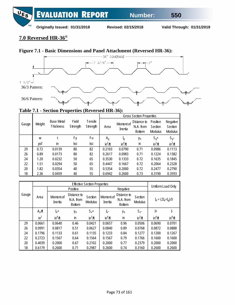
Number: 550
Originally Issued: 01/31/2018 Revised: 02/15/2018 Valid Through: 01/31/2019
Page 73 of 161
7.0 Reversed HR-36® Figure 7.1 - Basic Dimensions and Panel Attachment (Reversed HR-36):
36/3 Pattern:
36/6 Pattern:
Table 7.1 - Section Properties (Reversed HR-36):
Area Moment of Inertia
Distance to N.A. from
Bottom
Positive Section
Modulus
Negative Section
Modulusw t Fy Fu Ag Ig yb Sg+ Sg-
psf in ksi ksi in2/ft in4/ft in in3/ft in3/ft29 0.72 0.0139 80 82 0.2103 0.0790 0.71 0.0986 0.111326 0.89 0.0173 80 82 0.2617 0.0983 0.71 0.1224 0.138224 1.20 0.0232 50 65 0.3530 0.1333 0.72 0.1635 0.184522 1.51 0.0294 50 65 0.4447 0.1667 0.72 0.2064 0.232820 1.82 0.0354 40 55 0.5354 0.2000 0.72 0.2477 0.279018 2.36 0.0459 40 55 0.6942 0.2600 0.73 0.3190 0.3593
Moment of Inertia
Distance to N.A. from
Bottom
Section Modulus
Moment of Inertia
Distance to N.A. from
Bottom
Section Modulus
Ae/ft Ie+ yb Se+ Ie- yb Se- I+ I-
in2 in4/ft in in3/ft in4/ft in in3/ft in4/ft in4/ft29 0.0661 0.0640 0.46 0.0421 0.0657 0.96 0.0506 0.0690 0.070126 0.0991 0.0817 0.51 0.0627 0.0840 0.89 0.0768 0.0872 0.088824 0.1796 0.1133 0.61 0.1135 0.1233 0.84 0.1277 0.1200 0.126722 0.2723 0.1567 0.64 0.1564 0.1567 0.79 0.1766 0.1600 0.160020 0.4039 0.2000 0.67 0.2102 0.2000 0.77 0.2379 0.2000 0.200018 0.6179 0.2600 0.71 0.2987 0.2600 0.74 0.3160 0.2600 0.2600
Gauge Weight Base Metal Thickness
Yield Strength
Tensile Strength
Gross Section Properties
Gauge
Effective Section Properties Uniform Load Only
Area
Positive Negative
Id = (2Ie+Ig)/3

Number: 550
Originally Issued: 01/31/2018 Revised: 02/15/2018 Valid Through: 01/31/2019
Page 74 of 161
Table 7.2 - Inward (Positive) Uniform Allowable Load Table (Reversed HR-36):
Gauge Span Limit Condition
Panel Span (Support Spacing) 2' - 0" 2' - 6" 3' - 0" 4' - 0" 5' - 0" 6' - 0" 7' - 0" 8' - 0" 10' - 0"
29
Single Span
ASD, W/Ω LRFD, φW
252 400
161 256
112 178
63 100
40 64
28 44
21 33
16 25
10 16
L/240 L/180 L/120
- - -
- - -
- - -
- - -
36 - -
21 28 -
13 18 -
9 12 -
5 6 9
Double Span
ASD, W/Ω LRFD, φW
210 318
149 225
110 167
67 101
44 67
31 47
23 35
18 27
11 17
L/240 L/180 L/120
- - -
- - -
- - -
- - -
- - -
- - -
- - -
- - -
11 - -
Triple Span
ASD, W/Ω LRFD, φW
237 359
171 259
129 195
79 120
53 81
38 58
29 44
22 33
14 21
L/240 L/180 L/120
- - -
- - -
- - -
- - -
- - -
- - -
25 - -
17 - -
9 11 -
26
Single Span
ASD, W/Ω LRFD, φW
375 596
240 381
167 265
94 149
60 95
42 66
31 49
23 37
15 24
L/240 L/180 L/120
- - -
- - -
- - -
89 - -
46 - -
26 35 -
17 22 -
11 15 22
6 8 11
Double Span
ASD, W/Ω LRFD, φW
342 517
239 361
175 264
104 157
68 103
49 73
35 54
27 41
18 27
L/240 L/180 L/120
- - -
- - -
- - -
- - -
- - -
- - -
- - -
27 - -
14 - -
Triple Span
ASD, W/Ω LRFD, φW
392 593
279 421
207 313
126 190
84 127
60 90
44 67
34 51
22 33
L/240 L/180 L/120
- - -
- - -
- - -
- - -
- - -
50 - -
31 42 -
21 28 -
11 14 22
24
Single Span
ASD, W/Ω LRFD, φW
567 899
363 575
252 399
142 225
91 144
63 100
46 73
35 56
23 36
L/240 L/180 L/120
- - -
- - -
- - -
123 - -
63 84 -
36 49 -
23 31 46
15 20 31
8 10 16
Double Span
ASD, W/Ω LRFD, φW
555 836
371 559
265 399
153 230
99 149
69 104
50 76
39 59
25 38
L/240 L/180 L/120
- - -
- - -
- - -
- - -
- - -
- - -
- - -
37 - -
19 - -
Triple Span
ASD, W/ LRFD, φW
659 994
448 675
322 485
189 284
123 185
86 129
64 96
48 73
31 47
L/240 L/180 L/120
- - -
- - -
- - -
- - -
119 - -
69 - -
43 58 -
29 39 -
15 20 30

Number: 550
Originally Issued: 01/31/2018 Revised: 02/15/2018 Valid Through: 01/31/2019
Page 75 of 161
Table 7.2 (Cont’d) - Inward (Positive) Uniform Allowable Load Table (Reversed HR-36): Gauge Span Limit
Condition Panel Span (Support Spacing)
2' - 0" 2' - 6" 3' - 0" 4' - 0" 5' - 0" 6' - 0" 7' - 0" 8' - 0" 10' - 0" ASD, W/Ω 780 499 347 195 125 87 64 49 31 Single LRFD, φW 1238 792 550 310 198 138 101 77 50
L/240 L/180 L/120
- - -
- - -
- - -
164 - -
84 112
-
49 65 -
31 41 61
20 27 41
10 14 21
Span
ASD, W/Ω 794 526 373 214 138 97 71 54 35
22 Double Span
LRFD, φW 1195 791 561 322 208 145 107 81 53 L/240 L/180 L/120
- - -
- - -
- - -
- - -
- - -
- - -
- - -
49 - -
25 34 -
ASD, W/Ω 953 639 456 264 171 119 88 67 43 Triple LRFD, φW 1436 963 687 397 258 180 133 102 65
L/240 L/180 L/120
- - -
- - -
- - -
- - -
158 - -
92 - -
58 77 -
39 52 -
20 26 40
Span
ASD, W/Ω 839 537 373 210 134 93 69 52 34 Single LRFD, φW 1331 852 592 333 213 148 109 83 53
L/240 L/180 L/120
- - -
- - -
- - -
205 - -
105 - -
61 81 -
38 51 -
26 34 51
13 17 26
Span
ASD, W/Ω 867 572 404 231 149 104 76 58 38
20 Double Span
LRFD, φW 1306 861 608 348 224 156 115 88 57 L/240 L/180 L/120
- - -
- - -
- - -
- - -
- - -
- - -
- - -
- - -
32 - -
ASD, W/Ω 1046 698 496 286 185 129 96 73 47 Triple LRFD, φW 1576 1051 747 430 278 194 144 110 71
L/240 L/180 L/120
- - -
- - -
- - -
- - -
- - -
115 - -
72 - -
48 64 -
25 33 -
Span
ASD, W/Ω 1192 763 530 298 191 132 97 75 48 Single LRFD, φW 1892 1211 841 473 303 210 154 118 76
L/240 L/180 L/120
- - -
- - -
- - -
266 - -
136 182
-
79 105
-
50 66 -
33 44 67
17 23 34
Span
ASD, W/Ω 1146 758 536 307 198 138 102 78 50
18 Double Span
LRFD, φW 1726 1140 807 461 298 208 153 117 75 L/240 L/180 L/120
- - -
- - -
- - -
- - -
- - -
- - -
- - -
- - -
41 - -
ASD, W/Ω 1381 923 658 380 246 172 127 97 62 Triple LRFD, φW 2081 1390 990 571 370 259 191 146 93
L/240 L/180 L/120
- - -
- - -
- - -
- - -
- - -
149 - -
94 125
-
63 84 -
32 43 -
Span

Number: 550
Originally Issued: 01/31/2018 Revised: 02/15/2018 Valid Through: 01/31/2019
Page 76 of 161
Table 7.3 - Allowable Reactions at Supports (Reversed HR-36): Reactions at Supports based on Web Crippling
Gauge
Condition
Bearing Length of Webs ASD (Pn/Ω) (lbs/ft width) LRFD (φPn) (lbs/ft width)
1" 1.5" 2" 3" 1" 1.5" 2" 3"
29 End Interior
123 203
142 230
158 253
n/a n/a
188 302
217 342
241 376
n/a n/a
26 End Interior
188 310
215 349
239 382
278 438
287 461
330 520
365 569
425 651
24 End Interior
274 453
312 507
344 552
398 628
419 674
477 754
527 821
609 934
22 End Interior
428 711
485 791
533 858
614 970
655 1058
742 1176
815 1276
939 1443
20 End Interior
485 809
547 895
599 968
687 1090
742 1203
837 1331
917 1440
1052 1621
18 End Interior
788 1322
883 1454
964 1565
1098 1751
1205 1967
1351 2163
1474 2327
1681 2604

Number: 550
Originally Issued: 01/31/2018 Revised: 02/15/2018 Valid Through: 01/31/2019
Page 77 of 161
Table 7.4 - Outward (Negative) Uniform Allowable Loads (No. 29 gauge Reversed HR-36):
Thick- ness
ASD W/Ω
ASD W/Ω
ASD W/Ω
ASD W/Ω
ASD W/Ω
ASD W/Ω
ASD W/Ω
ASD W/Ω
ASD W/Ω
#12 36/6 285 228 187 105 67 47 34 26 17#12 36/3 142 114 95 71 57 47 34 26 17#12 36/6 285 228 187 105 67 47 34 26 17#12 36/3 142 114 95 71 57 47 34 26 17#12 36/6 278 223 186 105 67 47 34 26 17#12 36/3 139 111 93 70 56 46 34 26 17#12 36/6 235 188 156 105 67 47 34 26 17#12 36/3 117 94 78 59 47 39 34 26 17#12 36/6 183 146 122 91 67 47 34 26 17#12 36/3 91 73 61 46 37 30 26 23 17#12 36/6 141 113 94 70 56 47 34 26 17#12 36/3 70 56 47 35 28 23 20 18 14#12 36/6 117 94 78 58 47 39 33 26 17#12 36/3 58 47 39 29 23 19 17 15 12#12 36/6 285 228 187 105 67 47 34 26 17#12 36/3 142 114 95 71 57 47 34 26 17#12 36/6 285 228 187 105 67 47 34 26 17#12 36/3 142 114 95 71 57 47 34 26 17#12 36/6 193 154 129 96 67 47 34 26 17#12 36/3 96 77 64 48 39 32 28 24 17#12 36/6 162 130 108 81 65 47 34 26 17#12 36/3 81 65 54 41 32 27 23 20 16#12 36/6 126 101 84 63 51 42 34 26 17#12 36/3 63 51 42 32 25 21 18 16 13#12 36/6 97 78 65 49 39 32 28 24 17#12 36/3 49 39 32 24 19 16 14 12 10#12 36/6 81 65 54 40 32 27 23 20 16#12 36/3 40 32 27 20 16 13 12 10 8#14 36/6 105 84 70 52 42 35 30 26 17#14 36/3 52 42 35 26 21 17 15 13 10#14 36/6 133 106 88 66 53 44 34 26 17#14 36/3 66 53 44 33 27 22 19 17 13#14 36/6 161 128 107 80 64 47 34 26 17#14 36/3 80 64 54 40 32 27 23 20 16#9 36/6 194 155 129 97 67 47 34 26 17#9 36/3 97 78 65 48 39 32 28 24 17
#14 36/6 265 212 177 105 67 47 34 26 17#14 36/3 132 106 88 66 53 44 34 26 17
105 7443
4222
87
42
4227
74 54
2718
304224
29
107
18
42 27
2742
54
5448 41 36
272127
74
27
70 5974 54 42
5030
262 209 174
217 173
131
90
108 87 72145 108
54
113
14390 72
42
3514171 57 47
40
22119
36 3051
24
26
35 28179
60 4572
1494 71 57 47
182027
167285142
2727
7471
10785
74
58 2225
54
44
358179
286143
238119
16789
10772
7460
5451
4242
2727
72 54
5436
42 2731 27
27
131 65 52 44
46
88
27104 84 70
34 27
88
54
3974
35
42 2750
37 33 26
60
137274 219 183 137
110 91 68 5554 42
2642
4242107
5454
209167
107176 141 117352 282 235
167 139
Reversed HR-36, 29ga
Substrate
Fastener
Nom. Size
Attach.Pattern
167 107 74 54 42 27
Material/ Grade
Steel(Gr 50 min.)
427 342 285
117 88
106
704284
278 167
Panel System Negative (Outward) Uniform Load Capacity, (lbs/ft2)
84169
70141
53
LRFD φW
LRFD φW
LRFD φW
LRFD φW
LRFD φW
LRFD φW
LRFD φW
LRFD φW
LRFD φW
Attachment Spacing, (ft-in)
7035
54
214 85
27
54
22ga (.0294")
2' - 0" 2' - 6" 3' - 0" 4' - 0" 5' - 0"
175106211
140
≥10ga (.1350")
14ga (.0700")
16ga (.0590")
18ga (.0459")
12ga (.1050")
20ga (.0354")
107418 334
427214
342171
70
6' - 0"
58
171 142 107
27214 171 142 107 85 71
285 167 107 74 54
7' - 0" 8' - 0" 10' - 0"
42 2771
42
12ga (.1050")
427 342 285 167 107
16ga (.0590")
244 195 162 122 97
14ga (.0700")
122 97 81 61 49
145 116 96 72 58289 231 193 145 107 74
73 58
6135
41 3554
95 76 63 47 38 32 27
Steel(Gr 33 min.)
27
342
19
22ga (.0294")
121 97 81 61 49 40
49 4273 58 49 37
18ga (.0459")
190 152 126 95 76 63
15/32"
2415
37 27
2724
42 27
49 40 30 24 20 17
21 1830
29 2420ga
(.0354")146 117 97
19/32"
23/32"
1" min
Plywood & OSB
Lumber(DFL)
87105
42 27214 171 142 107 85 71 54 42
15 12
≥10ga (.1350")
427
2754 42

Number: 550
Originally Issued: 01/31/2018 Revised: 02/15/2018 Valid Through: 01/31/2019
Page 78 of 161
Table 7.5 - Outward (Negative) Uniform Allowable Loads (No. 26 gauge Reversed HR-36):
Thick- ness
ASD W/Ω
ASD W/Ω
ASD W/Ω
ASD W/Ω
ASD W/Ω
ASD W/Ω
ASD W/Ω
ASD W/Ω
ASD W/Ω
#12 36/6 355 284 236 156 100 70 51 39 25#12 36/3 177 142 118 89 71 59 51 39 25#12 36/6 355 284 236 156 100 70 51 39 25#12 36/3 177 142 118 89 71 59 51 39 25#12 36/6 278 223 186 139 100 70 51 39 25#12 36/3 139 111 93 70 56 46 40 35 25#12 36/6 235 188 156 117 94 70 51 39 25#12 36/3 117 94 78 59 47 39 34 29 23#12 36/6 183 146 122 91 73 61 51 39 25#12 36/3 91 73 61 46 37 30 26 23 18#12 36/6 141 113 94 70 56 47 40 35 25#12 36/3 70 56 47 35 28 23 20 18 14#12 36/6 117 94 78 58 47 39 33 29 23#12 36/3 58 47 39 29 23 19 17 15 12#12 36/6 355 284 236 156 100 70 51 39 25#12 36/3 177 142 118 89 71 59 51 39 25#12 36/6 289 231 193 145 100 70 51 39 25#12 36/3 145 116 96 72 58 48 41 36 25#12 36/6 193 154 129 96 77 64 51 39 25#12 36/3 96 77 64 48 39 32 28 24 19#12 36/6 162 130 108 81 65 54 46 39 25#12 36/3 81 65 54 41 32 27 23 20 16#12 36/6 126 101 84 63 51 42 36 32 25#12 36/3 63 51 42 32 25 21 18 16 13#12 36/6 97 78 65 49 39 32 28 24 19#12 36/3 49 39 32 24 19 16 14 12 10#12 36/6 81 65 54 40 32 27 23 20 16#12 36/3 40 32 27 20 16 13 12 10 8#14 36/6 105 84 70 52 42 35 30 26 21#14 36/3 52 42 35 26 21 17 15 13 10#14 36/6 133 106 88 66 53 44 38 33 25#14 36/3 66 53 44 33 27 22 19 17 13#14 36/6 161 128 107 80 64 54 46 39 25#14 36/3 80 64 54 40 32 27 23 20 16#9 36/6 194 155 129 97 78 65 51 39 25#9 36/3 97 78 65 48 39 32 28 24 19
#14 36/6 265 212 177 132 100 70 51 39 25#14 36/3 132 106 88 66 53 44 38 33 25
105 8743
5422
87
62
6240
110 81
3618
304724
29
141
18
62 40
4052
70
8148 41 36
352140
81
40
70 59110 81 62
5030
262 209 174
217 173
131
90
108 87 72145 108
54
113
14390 72
45
3514171 57 47
40
22119
36 3051
24
26
35 28179
60 4572
1494 71 57 47
182028
248355177
4040
11089
159106
110
58 2225
78
44
358179
286143
238119
17989
14372
11060
8151
6245
4036
72 62
7536
62 4031 27
40
131 65 52 44
46
88
40104 84 70
34 27
88
60
3991
35
44 3550
37 33 26
60
137274 219 183 137
110 91 68 5560 53
2644
6262133
8176
209176
110176 141 117352 282 235
167 139
Reversed HR-36, 26ga
Substrate
Fastener
Nom. Size
Attach.Pattern
248 159 110 81 62 40
Material/ Grade
Steel(Gr 50 min.)
532 426 355
117 88
106
704284
278 209
Panel System Negative (Outward) Uniform Load Capacity, (lbs/ft2)
84169
70141
53
LRFD φW
LRFD φW
LRFD φW
LRFD φW
LRFD φW
LRFD φW
LRFD φW
LRFD φW
LRFD φW
Attachment Spacing, (ft-in)
7035
81
266 106
40
76
22ga (.0294")
2' - 0" 2' - 6" 3' - 0" 4' - 0" 5' - 0"
175106211
140
≥10ga (.1350")
14ga (.0700")
16ga (.0590")
18ga (.0459")
12ga (.1050")
20ga (.0354")
159418 334
532266
426213
70
6' - 0"
58
213 177 133
40217 174 145 108 87 72
355 248 159 110 81
7' - 0" 8' - 0" 10' - 0"
62 4089
62
12ga (.1050")
434 347 289 217 159
16ga (.0590")
244 195 162 122 97
14ga (.0700")
122 97 81 61 49
145 116 96 72 58289 231 193 145 116 96
73 58
6135
41 3554
95 76 63 47 38 32 27
Steel(Gr 33 min.)
29
426
19
22ga (.0294")
121 97 81 61 49 40
49 4273 58 49 37
18ga (.0459")
190 152 126 95 76 63
15/32"
2415
37 29
3824
61 40
49 40 30 24 20 17
21 1830
29 2420ga
(.0354")146 117 97
19/32"
23/32"
1" min
Plywood & OSB
Lumber(DFL)
87105
62 40266 213 177 133 106 89 76 62
15 12
≥10ga (.1350")
532
4062 54

Number: 550
Originally Issued: 01/31/2018 Revised: 02/15/2018 Valid Through: 01/31/2019
Page 79 of 161
Table 7.6 - Outward (Negative) Uniform Allowable Loads (No. 24 gauge Reversed HR-36):
Thick- ness
ASD W/Ω
ASD W/Ω
ASD W/Ω
ASD W/Ω
ASD W/Ω
ASD W/Ω
ASD W/Ω
ASD W/Ω
ASD W/Ω
#12 36/6 377 302 251 177 113 79 58 44 28#12 36/3 189 151 126 94 75 63 54 44 28#12 36/6 377 302 251 177 113 79 58 44 28#12 36/3 189 151 126 94 75 63 54 44 28#12 36/6 278 223 186 139 111 79 58 44 28#12 36/3 139 111 93 70 56 46 40 35 28#12 36/6 235 188 156 117 94 78 58 44 28#12 36/3 117 94 78 59 47 39 34 29 23#12 36/6 183 146 122 91 73 61 52 44 28#12 36/3 91 73 61 46 37 30 26 23 18#12 36/6 141 113 94 70 56 47 40 35 28#12 36/3 70 56 47 35 28 23 20 18 14#12 36/6 117 94 78 58 47 39 33 29 23#12 36/3 58 47 39 29 23 19 17 15 12#12 36/6 372 297 248 177 113 79 58 44 28#12 36/3 186 149 124 93 74 62 53 44 28#12 36/6 289 231 193 145 113 79 58 44 28#12 36/3 145 116 96 72 58 48 41 36 28#12 36/6 193 154 129 96 77 64 55 44 28#12 36/3 96 77 64 48 39 32 28 24 19#12 36/6 162 130 108 81 65 54 46 41 28#12 36/3 81 65 54 41 32 27 23 20 16#12 36/6 126 101 84 63 51 42 36 32 25#12 36/3 63 51 42 32 25 21 18 16 13#12 36/6 97 78 65 49 39 32 28 24 19#12 36/3 49 39 32 24 19 16 14 12 10#12 36/6 81 65 54 40 32 27 23 20 16#12 36/3 40 32 27 20 16 13 12 10 8#14 36/6 105 84 70 52 42 35 30 26 21#14 36/3 52 42 35 26 21 17 15 13 10#14 36/6 133 106 88 66 53 44 38 33 27#14 36/3 66 53 44 33 27 22 19 17 13#14 36/6 161 128 107 80 64 54 46 40 28#14 36/3 80 64 54 40 32 27 23 20 16#9 36/6 194 155 129 97 78 65 55 44 28#9 36/3 97 78 65 48 39 32 28 24 19
#14 36/6 265 212 177 132 106 79 58 44 28#14 36/3 132 106 88 66 53 44 38 33 26
105 8743
5422
87
70
7043
125 92
3618
304724
29
141
18
68 45
4552
70
8348 41 36
352142
81
45
70 59117 92 70
5030
262 209 174
217 173
131
90
108 87 72145 108
54
113
14390 72
45
3514171 57 47
40
22119
36 3051
24
26
35 28179
60 4572
1494 71 57 47
182028
281377189
4545
12594
180113
125
58 2225
78
44
358179
286143
238119
17989
14372
11960
9251
7045
4536
72 62
7536
65 4531 27
43
131 65 52 44
46
88
42104 84 70
34 27
88
60
3991
35
44 3550
37 33 26
60
137274 219 183 137
110 91 68 5560 53
2644
7070141
9281
209176
110176 141 117352 282 235
167 139
Reversed HR-36, 24ga
Substrate
Fastener
Nom. Size
Attach.Pattern
281 180 125 92 70 45
Material/ Grade
Steel(Gr 50 min.)
566 452 377
117 88
106
704284
278 209
Panel System Negative (Outward) Uniform Load Capacity, (lbs/ft2)
84169
70141
53
LRFD φW
LRFD φW
LRFD φW
LRFD φW
LRFD φW
LRFD φW
LRFD φW
LRFD φW
LRFD φW
Attachment Spacing, (ft-in)
7035
92
283 113
45
81
22ga (.0294")
2' - 0" 2' - 6" 3' - 0" 4' - 0" 5' - 0"
175106211
140
≥10ga (.1350")
14ga (.0700")
16ga (.0590")
18ga (.0459")
12ga (.1050")
20ga (.0354")
167418 334
566283
452226
70
6' - 0"
58
226 189 141
45217 174 145 108 87 72
372 279 180 125 92
7' - 0" 8' - 0" 10' - 0"
70 4594
70
12ga (.1050")
434 347 289 217 174
16ga (.0590")
244 195 162 122 97
14ga (.0700")
122 97 81 61 49
145 116 96 72 58289 231 193 145 116 96
73 58
6135
41 3554
95 76 63 47 38 32 27
Steel(Gr 33 min.)
29
446
19
22ga (.0294")
121 97 81 61 49 40
49 4273 58 49 37
18ga (.0459")
190 152 126 95 76 63
15/32"
2415
37 29
3824
61 45
49 40 30 24 20 17
21 1830
29 2420ga
(.0354")146 117 97
19/32"
23/32"
1" min
Plywood & OSB
Lumber(DFL)
87105
70 45279 223 186 139 112 93 80 70
15 12
≥10ga (.1350")
558
4562 54

Number: 550
Originally Issued: 01/31/2018 Revised: 02/15/2018 Valid Through: 01/31/2019
Page 80 of 161
Table 7.7 - Outward (Negative) Uniform Allowable Loads (No. 22 gauge Reversed HR-36):
Thick- ness
ASD W/Ω
ASD W/Ω
ASD W/Ω
ASD W/Ω
ASD W/Ω
ASD W/Ω
ASD W/Ω
ASD W/Ω
ASD W/Ω
#12 36/6 478 382 319 239 156 108 80 61 39#12 36/3 239 191 159 119 96 80 68 60 39#12 36/6 418 334 278 209 156 108 80 61 39#12 36/3 209 167 139 104 84 70 60 52 39#12 36/6 278 223 186 139 111 93 80 61 39#12 36/3 139 111 93 70 56 46 40 35 28#12 36/6 235 188 156 117 94 78 67 59 39#12 36/3 117 94 78 59 47 39 34 29 23#12 36/6 183 146 122 91 73 61 52 46 37#12 36/3 91 73 61 46 37 30 26 23 18#12 36/6 141 113 94 70 56 47 40 35 28#12 36/3 70 56 47 35 28 23 20 18 14#12 36/6 117 94 78 58 47 39 33 29 23#12 36/3 58 47 39 29 23 19 17 15 12#12 36/6 372 297 248 186 149 108 80 61 39#12 36/3 186 149 124 93 74 62 53 46 37#12 36/6 289 231 193 145 116 96 80 61 39#12 36/3 145 116 96 72 58 48 41 36 29#12 36/6 193 154 129 96 77 64 55 48 39#12 36/3 96 77 64 48 39 32 28 24 19#12 36/6 162 130 108 81 65 54 46 41 32#12 36/3 81 65 54 41 32 27 23 20 16#12 36/6 126 101 84 63 51 42 36 32 25#12 36/3 63 51 42 32 25 21 18 16 13#12 36/6 97 78 65 49 39 32 28 24 19#12 36/3 49 39 32 24 19 16 14 12 10#12 36/6 81 65 54 40 32 27 23 20 16#12 36/3 40 32 27 20 16 13 12 10 8#14 36/6 105 84 70 52 42 35 30 26 21#14 36/3 52 42 35 26 21 17 15 13 10#14 36/6 133 106 88 66 53 44 38 33 27#14 36/3 66 53 44 33 27 22 19 17 13#14 36/6 161 128 107 80 64 54 46 40 32#14 36/3 80 64 54 40 32 27 23 20 16#9 36/6 194 155 129 97 78 65 55 48 39#9 36/3 97 78 65 48 39 32 28 24 19
#14 36/6 265 212 177 132 106 88 76 61 39#14 36/3 132 106 88 66 53 44 38 33 26
105 8743
5422
87
72
9743
145 124
3618
304724
29
141
18
68 55
6252
70
8348 41 36
352142
81
56
70 59117 101 88
5030
262 209 174
217 173
131
90
108 87 72145 108
54
113
14390 72
45
3514171 57 47
40
22119
36 3051
24
26
35 28179
60 4572
1494 71 57 47
182028
313418209
6262
172104
248125
139
58 2225
78
44
358179
286143
238119
17989
14372
11960
10251
8945
6236
72 62
7536
65 5231 27
43
131 65 52 44
46
88
42104 84 70
34 27
88
60
3991
35
44 3550
37 33 26
60
137274 219 183 137
110 91 68 5560 53
2644
9778157
12690
209176
110176 141 117352 282 235
167 139
Reversed HR-36, 22ga
Substrate
Fastener
Nom. Size
Attach.Pattern
358 248 172 126 97 62
Material/ Grade
Steel(Gr 50 min.)
717 573 478
117 88
106
704284
278 209
Panel System Negative (Outward) Uniform Load Capacity, (lbs/ft2)
84169
70141
53
LRFD φW
LRFD φW
LRFD φW
LRFD φW
LRFD φW
LRFD φW
LRFD φW
LRFD φW
LRFD φW
Attachment Spacing, (ft-in)
7035
119
358 143
62
102
22ga (.0294")
2' - 0" 2' - 6" 3' - 0" 4' - 0" 5' - 0"
175106211
140
≥10ga (.1350")
14ga (.0700")
16ga (.0590")
18ga (.0459")
12ga (.1050")
20ga (.0354")
167418 334
627313
501251
70
6' - 0"
58
287 239 179
62217 174 145 108 87 72
372 279 223 172 126
7' - 0" 8' - 0" 10' - 0"
90 62119
97
12ga (.1050")
434 347 289 217 174
16ga (.0590")
244 195 162 122 97
14ga (.0700")
122 97 81 61 49
145 116 96 72 58289 231 193 145 116 96
73 58
6135
41 3554
95 76 63 47 38 32 27
Steel(Gr 33 min.)
29
446
19
22ga (.0294")
121 97 81 61 49 40
49 4273 58 49 37
18ga (.0459")
190 152 126 95 76 63
15/32"
2415
37 29
3824
61 49
49 40 30 24 20 17
21 1830
29 2420ga
(.0354")146 117 97
19/32"
23/32"
1" min
Plywood & OSB
Lumber(DFL)
87105
97 62279 223 186 139 112 93 80 70
15 12
≥10ga (.1350")
558
5862 54

Number: 550
Originally Issued: 01/31/2018 Revised: 02/15/2018 Valid Through: 01/31/2019
Page 81 of 161
Table 7.8 - Outward (Negative) Uniform Allowable Loads (No. 20 gauge Reversed HR-36):
Thick- ness
ASD W/Ω
ASD W/Ω
ASD W/Ω
ASD W/Ω
ASD W/Ω
ASD W/Ω
ASD W/Ω
ASD W/Ω
ASD W/Ω
#12 36/6 487 389 325 243 168 117 86 66 42#12 36/3 243 195 162 122 97 81 70 61 42#12 36/6 418 334 278 209 167 117 86 66 42#12 36/3 209 167 139 104 84 70 60 52 42#12 36/6 278 223 186 139 111 93 80 66 42#12 36/3 139 111 93 70 56 46 40 35 28#12 36/6 235 188 156 117 94 78 67 59 42#12 36/3 117 94 78 59 47 39 34 29 23#12 36/6 183 146 122 91 73 61 52 46 37#12 36/3 91 73 61 46 37 30 26 23 18#12 36/6 141 113 94 70 56 47 40 35 28#12 36/3 70 56 47 35 28 23 20 18 14#12 36/6 117 94 78 58 47 39 33 29 23#12 36/3 58 47 39 29 23 19 17 15 12#12 36/6 372 297 248 186 149 117 86 66 42#12 36/3 186 149 124 93 74 62 53 46 37#12 36/6 289 231 193 145 116 96 83 66 42#12 36/3 145 116 96 72 58 48 41 36 29#12 36/6 193 154 129 96 77 64 55 48 39#12 36/3 96 77 64 48 39 32 28 24 19#12 36/6 162 130 108 81 65 54 46 41 32#12 36/3 81 65 54 41 32 27 23 20 16#12 36/6 126 101 84 63 51 42 36 32 25#12 36/3 63 51 42 32 25 21 18 16 13#12 36/6 97 78 65 49 39 32 28 24 19#12 36/3 49 39 32 24 19 16 14 12 10#12 36/6 81 65 54 40 32 27 23 20 16#12 36/3 40 32 27 20 16 13 12 10 8#14 36/6 105 84 70 52 42 35 30 26 21#14 36/3 52 42 35 26 21 17 15 13 10#14 36/6 133 106 88 66 53 44 38 33 27#14 36/3 66 53 44 33 27 22 19 17 13#14 36/6 161 128 107 80 64 54 46 40 32#14 36/3 80 64 54 40 32 27 23 20 16#9 36/6 194 155 129 97 78 65 55 48 39#9 36/3 97 78 65 48 39 32 28 24 19
#14 36/6 265 212 177 132 106 88 76 66 42#14 36/3 132 106 88 66 53 44 38 33 26
105 8743
5422
87
72
10443
145 124
3618
304724
29
141
18
68 55
6752
70
8348 41 36
352142
81
56
70 59117 101 88
5030
262 209 174
217 173
131
90
108 87 72145 108
54
113
14390 72
45
3514171 57 47
40
22119
36 3051
24
26
35 28179
60 4572
1494 71 57 47
182028
313418209
6763
185104
251125
139
58 2225
78
44
358179
286143
238119
17989
14372
11960
10251
8945
6736
72 62
7536
65 5231 27
43
131 65 52 44
46
88
42104 84 70
34 27
88
60
3991
35
44 3550
37 33 26
60
137274 219 183 137
110 91 68 5560 53
2644
10478157
13690
209176
110176 141 117352 282 235
167 139
Reversed HR-36, 20ga
Substrate
Fastener
Nom. Size
Attach.Pattern
365 266 185 136 104 67
Material/ Grade
Steel(Gr 50 min.)
730 584 487
117 88
106
704284
278 209
Panel System Negative (Outward) Uniform Load Capacity, (lbs/ft2)
84169
70141
53
LRFD φW
LRFD φW
LRFD φW
LRFD φW
LRFD φW
LRFD φW
LRFD φW
LRFD φW
LRFD φW
Attachment Spacing, (ft-in)
7035
119
365 146
67
104
22ga (.0294")
2' - 0" 2' - 6" 3' - 0" 4' - 0" 5' - 0"
175106211
140
≥10ga (.1350")
14ga (.0700")
16ga (.0590")
18ga (.0459")
12ga (.1050")
20ga (.0354")
167418 334
627313
501251
70
6' - 0"
58
292 243 183
67217 174 145 108 87 72
372 279 223 185 136
7' - 0" 8' - 0" 10' - 0"
91 67122
104
12ga (.1050")
434 347 289 217 174
16ga (.0590")
244 195 162 122 97
14ga (.0700")
122 97 81 61 49
145 116 96 72 58289 231 193 145 116 96
73 58
6135
41 3554
95 76 63 47 38 32 27
Steel(Gr 33 min.)
29
446
19
22ga (.0294")
121 97 81 61 49 40
49 4273 58 49 37
18ga (.0459")
190 152 126 95 76 63
15/32"
2415
37 29
3824
61 49
49 40 30 24 20 17
21 1830
29 2420ga
(.0354")146 117 97
19/32"
23/32"
1" min
Plywood & OSB
Lumber(DFL)
87105
104 67279 223 186 139 112 93 80 70
15 12
≥10ga (.1350")
558
5862 54

Number: 550
Originally Issued: 01/31/2018 Revised: 02/15/2018 Valid Through: 01/31/2019
Page 82 of 161
Table 7.9 - Outward (Negative) Uniform Allowable Loads (No. 18 gauge Reversed HR-36):
Thick- ness
ASD W/Ω
ASD W/Ω
ASD W/Ω
ASD W/Ω
ASD W/Ω
ASD W/Ω
ASD W/Ω
ASD W/Ω
ASD W/Ω
#12 36/6 537 430 358 269 215 166 122 93 60#12 36/3 269 215 179 134 107 90 77 67 54#12 36/6 418 334 278 209 167 139 119 93 60#12 36/3 209 167 139 104 84 70 60 52 42#12 36/6 278 223 186 139 111 93 80 70 56#12 36/3 139 111 93 70 56 46 40 35 28#12 36/6 235 188 156 117 94 78 67 59 47#12 36/3 117 94 78 59 47 39 34 29 23#12 36/6 183 146 122 91 73 61 52 46 37#12 36/3 91 73 61 46 37 30 26 23 18#12 36/6 141 113 94 70 56 47 40 35 28#12 36/3 70 56 47 35 28 23 20 18 14#12 36/6 117 94 78 58 47 39 33 29 23#12 36/3 58 47 39 29 23 19 17 15 12#12 36/6 372 297 248 186 149 124 106 93 60#12 36/3 186 149 124 93 74 62 53 46 37#12 36/6 289 231 193 145 116 96 83 72 58#12 36/3 145 116 96 72 58 48 41 36 29#12 36/6 193 154 129 96 77 64 55 48 39#12 36/3 96 77 64 48 39 32 28 24 19#12 36/6 162 130 108 81 65 54 46 41 32#12 36/3 81 65 54 41 32 27 23 20 16#12 36/6 126 101 84 63 51 42 36 32 25#12 36/3 63 51 42 32 25 21 18 16 13#12 36/6 97 78 65 49 39 32 28 24 19#12 36/3 49 39 32 24 19 16 14 12 10#12 36/6 81 65 54 40 32 27 23 20 16#12 36/3 40 32 27 20 16 13 12 10 8#14 36/6 105 84 70 52 42 35 30 26 21#14 36/3 52 42 35 26 21 17 15 13 10#14 36/6 133 106 88 66 53 44 38 33 27#14 36/3 66 53 44 33 27 22 19 17 13#14 36/6 161 128 107 80 64 54 46 40 32#14 36/3 80 64 54 40 32 27 23 20 16#9 36/6 194 155 129 97 78 65 55 48 39#9 36/3 97 78 65 48 39 32 28 24 19
#14 36/6 265 212 177 132 106 88 76 66 53#14 36/3 132 106 88 66 53 44 38 33 26
105 8743
5422
87
72
10843
145 124
3618
304724
29
141
18
68 55
7052
70
8348 41 36
352142
81
56
70 59117 101 88
5030
262 209 174
217 173
131
90
108 87 72145 108
54
113
14390 72
45
3514171 57 47
40
22119
36 3051
24
26
35 28179
60 4572
1494 71 57 47
182028
313418209
9563
209104
251125
139
58 2225
78
44
358179
286143
238119
17989
14372
11960
10251
8945
7236
72 62
7536
65 5231 27
43
131 65 52 44
46
88
42104 84 70
34 27
88
60
3991
35
44 3550
37 33 26
60
137274 219 183 137
110 91 68 5560 53
2644
14878157
17990
209176
110176 141 117352 282 235
167 139
Reversed HR-36, 18ga
Substrate
Fastener
Nom. Size
Attach.Pattern
403 322 263 193 148 95
Material/ Grade
Steel(Gr 50 min.)
806 644 537
117 88
106
704284
278 209
Panel System Negative (Outward) Uniform Load Capacity, (lbs/ft2)
84169
70141
53
LRFD φW
LRFD φW
LRFD φW
LRFD φW
LRFD φW
LRFD φW
LRFD φW
LRFD φW
LRFD φW
Attachment Spacing, (ft-in)
7035
119
403 161
84
115
22ga (.0294")
2' - 0" 2' - 6" 3' - 0" 4' - 0" 5' - 0"
175106211
140
≥10ga (.1350")
14ga (.0700")
16ga (.0590")
18ga (.0459")
12ga (.1050")
20ga (.0354")
167418 334
627313
501251
70
6' - 0"
58
322 269 201
87217 174 145 108 87 72
372 279 223 186 159
7' - 0" 8' - 0" 10' - 0"
101 81134
104
12ga (.1050")
434 347 289 217 174
16ga (.0590")
244 195 162 122 97
14ga (.0700")
122 97 81 61 49
145 116 96 72 58289 231 193 145 116 96
73 58
6135
41 3554
95 76 63 47 38 32 27
Steel(Gr 33 min.)
29
446
19
22ga (.0294")
121 97 81 61 49 40
49 4273 58 49 37
18ga (.0459")
190 152 126 95 76 63
15/32"
2415
37 29
3824
61 49
49 40 30 24 20 17
21 1830
29 2420ga
(.0354")146 117 97
19/32"
23/32"
1" min
Plywood & OSB
Lumber(DFL)
87105
139 95279 223 186 139 112 93 80 70
15 12
≥10ga (.1350")
558
5862 54

Number: 550
Originally Issued: 01/31/2018 Revised: 02/15/2018 Valid Through: 01/31/2019
Page 83 of 161
Table 7.10 - Shear and Flexibility (No. 29 gauge Reversed HR-36, 36/3):
Table 7.11 - Shear and Flexibility (No. 29 gauge Reversed HR-36, 36/6):
29ga Reverse HR-36 36/3 Attachment Pattern Support Screw: #12 HWH Side Lap Screw: #12 SD
ASD Sn/Ω
LRFD φSn
ASD Sn/Ω
LRFD φSn
ASD Sn/Ω
LRFD φSn
ASD Sn/Ω
LRFD φSn
ASD Sn/Ω
LRFD φSn
ASD Sn/Ω
LRFD φSn
ASD Sn/Ω
LRFD φSn
ASD Sn/Ω
LRFD φSn
ASD Sn/Ω
LRFD φSn
q 251 407 251 408 250 406 249 405 249 404 248 403 248 403 248 403 229 366F q 236 384 236 383 235 382 228 371 229 372 225 365 226 367 223 362 222 360F q 223 363 225 366 214 348 208 338 204 332 201 327 199 324 198 321 195 317F q 198 322 208 339 194 315 167 272 171 278 153 248 158 257 145 235 139 227F q 198 322 178 290 161 261 167 272 145 236 127 206 137 223 124 202 123 199F q 198 322 178 290 161 261 132 215 145 236 127 206 112 183 101 164 104 169F
1 q 198 322 178 290 161 261 132 215 111 180 94 152 80 130 70 114 56 91per span F
q 146 237 124 202 107 174 79 129 61 100 50 82 43 70 38 61 30 49F
Attachment Spacing, (ft-in)Diaphragm Shear Capacities, q (plf) and Flexibility Factors, F (10-6 in/lbs)
219.0
2' - 0" 2' - 6" 3' - 0" 4' - 0" 5' - 0" 6' - 0" 7' - 0" 8' - 0" 10' - 0"
181.6
183.8
187.0
200.4
171.6
174.0
176.1
273.2
211.9
249.3
248.5
250.7
254.2
260.1
240.7
242.8
244.9
214.2
216.3
221.2
223.7
227.6
234.5
355.4
279.1
281.3
283.1
287.4
290.3
290.3
295.4
306.6
339.4
341.8
341.8
346.1
332.9
334.7
336.7
560.6
413.5
415.5
417.0
420.3
420.3
423.7
423.7
431.1
552.5
555.1
555.1
555.1
548.0
549.4
551.0
821.0
824.7
655.4
657.0
657.8
659.0
661.1
661.1
661.1
665.8
819.3
821.0
821.0
821.0
816.9
818.3
none
4"
8"
12"
24"
36"
48"
Side Seam Spacing
29ga Reverse HR-36 36/6 Attachment Pattern Support Screw: #12 HWH Side Lap Screw: #12 SD
ASD Sn/Ω
LRFD φSn
ASD Sn/Ω
LRFD φSn
ASD Sn/Ω
LRFD φSn
ASD Sn/Ω
LRFD φSn
ASD Sn/Ω
LRFD φSn
ASD Sn/Ω
LRFD φSn
ASD Sn/Ω
LRFD φSn
ASD Sn/Ω
LRFD φSn
ASD Sn/Ω
LRFD φSn
q 463 753 464 753 455 739 450 732 447 726 445 723 443 720 357 572 229 366F q 402 652 396 643 391 636 364 592 365 593 349 567 352 571 340 553 229 366F q 361 587 362 589 327 532 307 499 294 478 285 463 278 452 273 443 229 366F q 303 492 318 517 282 457 226 368 227 370 195 317 201 326 179 291 169 274F q 303 492 259 420 224 364 226 368 187 305 159 258 171 277 151 246 146 238F q 303 492 259 420 224 364 175 285 187 305 159 258 136 221 119 194 121 197F
1 q 303 492 259 420 224 364 175 285 140 227 115 188 99 161 87 141 69 113per span F
q 220 357 182 295 153 248 112 182 88 143 72 117 62 101 54 88 43 70F
Attachment Spacing, (ft-in)Diaphragm Shear Capacities, q (plf) and Flexibility Factors, F (10-6 in/lbs)
42.1
2' - 0" 2' - 6" 3' - 0" 4' - 0" 5' - 0" 6' - 0" 7' - 0" 8' - 0" 10' - 0"
22.4
24.0
26.2
34.0
14.1
16.3
18.2
34.7
15.1
37.0
22.0
23.5
25.7
29.0
15.8
17.6
19.3
17.1
18.8
22.6
24.3
26.8
30.5
30.9
16.7
18.5
20.0
23.0
24.9
24.9
27.7
32.6
22.9
24.5
24.5
26.8
18.0
19.5
21.0
30.2
19.9
21.5
22.6
24.7
24.7
26.6
26.6
29.9
26.4
27.8
27.8
27.8
23.2
24.3
25.4
32.3
33.9
25.7
26.9
27.4
28.2
29.4
29.4
29.4
31.4
31.4
32.3
32.3
32.3
29.7
30.7
none
4"
8"
12"
24"
36"
48"
Side Seam Spacing

Number: 550
Originally Issued: 01/31/2018 Revised: 02/15/2018 Valid Through: 01/31/2019
Page 84 of 161
Table 7.12 - Shear and Flexibility (No. 26 gauge Reversed HR-36, 36/3):
Table 7.13 - Shear and Flexibility (No. 26 gauge Reversed HR-36, 36/6):
26ga Reverse HR-36 36/3 Attachment Pattern Support Screw: #12 HWH Side Lap Screw: #12 SD
ASD Sn/Ω
LRFD φSn
ASD Sn/Ω
LRFD φSn
ASD Sn/Ω
LRFD φSn
ASD Sn/Ω
LRFD φSn
ASD Sn/Ω
LRFD φSn
ASD Sn/Ω
LRFD φSn
ASD Sn/Ω
LRFD φSn
ASD Sn/Ω
LRFD φSn
ASD Sn/Ω
LRFD φSn
q 312 507 312 508 311 505 310 503 309 503 309 502 309 502 308 501 308 501F q 294 478 293 476 293 475 284 462 285 464 280 455 281 457 277 451 276 448F q 278 452 281 456 266 433 259 421 254 413 251 407 248 403 246 400 243 394F q 247 401 259 422 241 392 208 338 213 345 190 309 197 320 180 293 174 282F q 247 401 222 361 200 325 208 338 180 293 158 257 171 278 155 252 153 248F q 247 401 222 361 200 325 164 267 180 293 158 257 140 227 125 204 129 210F
1 q 247 401 222 361 200 325 164 267 138 224 117 190 100 162 87 142 70 114per span F
q 182 296 155 251 134 217 100 162 78 126 63 102 54 87 47 76 38 61F
Attachment Spacing, (ft-in)Diaphragm Shear Capacities, q (plf) and Flexibility Factors, F (10-6 in/lbs)
144.3
2' - 0" 2' - 6" 3' - 0" 4' - 0" 5' - 0" 6' - 0" 7' - 0" 8' - 0" 10' - 0"
110.8
112.8
115.6
127.6
101.8
104.0
105.9
170.9
125.1
158.7
148.8
150.8
153.9
159.2
141.8
143.6
145.6
127.2
129.0
133.4
135.7
139.2
145.3
215.3
164.0
165.9
167.6
171.4
174.0
174.0
178.6
188.6
200.9
203.1
203.1
206.9
195.1
196.7
198.5
330.9
241.8
243.5
244.9
247.8
247.8
250.8
250.8
257.5
323.6
325.9
325.9
325.9
319.5
320.8
322.3
478.8
482.1
381.6
383.0
383.7
384.8
386.7
386.7
386.7
390.9
477.2
478.8
478.8
478.8
475.1
476.3
none
4"
8"
12"
24"
36"
48"
Side Seam Spacing
26ga Reverse HR-36 36/6 Attachment Pattern Support Screw: #12 HWH Side Lap Screw: #12 SD
ASD Sn/Ω
LRFD φSn
ASD Sn/Ω
LRFD φSn
ASD Sn/Ω
LRFD φSn
ASD Sn/Ω
LRFD φSn
ASD Sn/Ω
LRFD φSn
ASD Sn/Ω
LRFD φSn
ASD Sn/Ω
LRFD φSn
ASD Sn/Ω
LRFD φSn
ASD Sn/Ω
LRFD φSn
q 577 937 577 938 566 920 560 910 556 904 554 900 552 896 497 796 318 509F q 500 812 492 800 487 792 454 737 454 738 434 706 438 711 424 688 318 509F q 450 731 451 733 407 662 383 622 366 595 355 576 346 562 340 552 318 509F q 377 612 396 643 350 569 281 457 283 460 243 395 250 406 223 362 210 341F q 377 612 322 523 279 453 281 457 233 379 198 322 212 345 188 306 182 296F q 377 612 322 523 279 453 218 355 233 379 198 322 169 275 148 241 151 245F
1 q 377 612 322 523 279 453 218 355 175 285 144 234 123 200 108 175 86 140per span F
q 274 445 226 368 191 310 141 229 110 180 90 147 77 125 67 109 54 88F
Attachment Spacing, (ft-in)Diaphragm Shear Capacities, q (plf) and Flexibility Factors, F (10-6 in/lbs)
35.8
2' - 0" 2' - 6" 3' - 0" 4' - 0" 5' - 0" 6' - 0" 7' - 0" 8' - 0" 10' - 0"
18.1
19.6
21.5
28.5
10.7
12.6
14.3
28.6
11.2
30.9
17.2
18.6
20.5
23.5
11.6
13.2
14.8
13.0
14.6
17.9
19.5
21.7
25.1
24.4
12.1
13.8
15.1
17.8
19.5
19.5
22.0
26.4
17.3
18.7
18.7
20.8
12.8
14.2
15.6
22.1
13.9
15.3
16.4
18.2
18.2
19.9
19.9
22.8
18.6
19.9
19.9
19.9
15.8
16.8
17.8
21.8
23.3
17.2
18.2
18.7
19.4
20.4
20.4
20.4
22.3
21.0
21.8
21.8
21.8
19.5
20.4
none
4"
8"
12"
24"
36"
48"
Side Seam Spacing

Number: 550
Originally Issued: 01/31/2018 Revised: 02/15/2018 Valid Through: 01/31/2019
Page 85 of 161
Table 7.14 - Shear and Flexibility (No. 24 gauge Reversed HR-36, 36/3):
Table 7.15 - Shear and Flexibility (No. 24 gauge Reversed HR-36, 36/6):
24ga Reverse HR-36 36/3 Attachment Pattern Support Screw: #12 HWH Side Lap Screw: #12 SD
ASD Sn/Ω
LRFD φSn
ASD Sn/Ω
LRFD φSn
ASD Sn/Ω
LRFD φSn
ASD Sn/Ω
LRFD φSn
ASD Sn/Ω
LRFD φSn
ASD Sn/Ω
LRFD φSn
ASD Sn/Ω
LRFD φSn
ASD Sn/Ω
LRFD φSn
ASD Sn/Ω
LRFD φSn
q 332 539 332 540 330 537 329 535 329 534 328 534 328 533 328 533 328 532F q 312 508 312 506 311 505 302 491 303 493 298 483 299 486 295 479 293 477F q 295 480 298 485 283 460 276 448 270 439 266 433 264 428 261 425 258 419F q 262 426 276 448 256 417 221 359 226 367 202 328 209 340 191 311 185 300F q 262 426 236 384 213 345 221 359 192 312 168 273 182 295 165 267 162 264F q 262 426 236 384 213 345 175 284 192 312 168 273 149 242 133 216 137 223F
1 q 262 426 236 384 213 345 175 284 147 238 126 204 107 173 93 151 74 121per span F
q 193 314 164 267 142 231 107 175 84 137 69 111 57 93 50 81 40 65F
Attachment Spacing, (ft-in)Diaphragm Shear Capacities, q (plf) and Flexibility Factors, F (10-6 in/lbs)
88.1
2' - 0" 2' - 6" 3' - 0" 4' - 0" 5' - 0" 6' - 0" 7' - 0" 8' - 0" 10' - 0"
59.1
60.8
63.3
73.7
51.4
53.2
54.9
95.7
62.6
91.6
76.6
78.3
81.0
85.6
70.6
72.2
73.8
64.4
65.9
69.8
71.7
74.8
80.0
113.6
81.2
82.9
84.3
87.6
89.9
89.9
93.9
102.5
101.2
103.1
103.1
106.4
96.1
97.6
99.1
165.6
118.5
120.0
121.2
123.7
123.7
126.4
126.4
132.1
159.3
161.3
161.3
161.3
155.8
156.9
158.2
233.6
236.5
185.6
186.8
187.4
188.3
190.0
190.0
190.0
193.6
232.3
233.6
233.6
233.6
230.5
231.6
none
4"
8"
12"
24"
36"
48"
Side Seam Spacing
24ga Reverse HR-36 36/6 Attachment Pattern Support Screw: #12 HWH Side Lap Screw: #12 SD
ASD Sn/Ω
LRFD φSn
ASD Sn/Ω
LRFD φSn
ASD Sn/Ω
LRFD φSn
ASD Sn/Ω
LRFD φSn
ASD Sn/Ω
LRFD φSn
ASD Sn/Ω
LRFD φSn
ASD Sn/Ω
LRFD φSn
ASD Sn/Ω
LRFD φSn
ASD Sn/Ω
LRFD φSn
q 613 996 613 997 602 978 596 968 591 961 589 956 586 953 585 950 497 796F q 531 863 523 850 518 841 482 783 483 785 462 750 465 756 450 732 443 720F q 478 777 480 779 433 704 407 661 389 633 377 613 368 598 361 586 351 570F q 401 651 421 684 372 605 299 486 301 489 258 420 266 432 237 385 223 363F q 401 651 342 556 296 482 299 486 248 403 211 343 226 367 200 325 194 315F q 401 651 342 556 296 482 232 377 248 403 211 343 181 293 158 256 160 261F
1 q 401 651 342 556 296 482 232 377 188 305 155 252 131 214 115 186 92 149per span F
q 291 473 240 391 204 332 151 245 119 193 98 159 82 134 72 116 57 93F
Attachment Spacing, (ft-in)Diaphragm Shear Capacities, q (plf) and Flexibility Factors, F (10-6 in/lbs)
29.3
2' - 0" 2' - 6" 3' - 0" 4' - 0" 5' - 0" 6' - 0" 7' - 0" 8' - 0" 10' - 0"
14.0
15.3
17.0
23.0
7.6
9.3
10.7
22.7
7.8
24.8
12.9
14.0
15.7
18.3
8.0
9.4
10.8
9.4
10.7
13.6
15.0
16.9
19.8
18.6
8.2
9.7
10.8
13.2
14.6
14.6
16.8
20.6
12.4
13.6
13.6
15.4
8.6
9.8
10.9
15.3
9.1
10.3
11.2
12.8
12.8
14.3
14.3
16.8
12.4
13.5
13.5
13.5
9.9
10.8
11.6
13.6
14.9
10.5
11.4
11.8
12.4
13.3
13.3
13.3
14.9
12.9
13.6
13.6
13.6
11.6
12.4
none
4"
8"
12"
24"
36"
48"
Side Seam Spacing

Number: 550
Originally Issued: 01/31/2018 Revised: 02/15/2018 Valid Through: 01/31/2019
Page 86 of 161
Table 7.16 - Shear and Flexibility (No. 22 gauge Reversed HR-36, 36/3):
Table 7.17 - Shear and Flexibility (No. 22 gauge Reversed HR-36, 36/6):
22ga Reverse HR-36 36/3 Attachment Pattern Support Screw: #12 HWH Side Lap Screw: #12 SD
ASD Sn/Ω
LRFD φSn
ASD Sn/Ω
LRFD φSn
ASD Sn/Ω
LRFD φSn
ASD Sn/Ω
LRFD φSn
ASD Sn/Ω
LRFD φSn
ASD Sn/Ω
LRFD φSn
ASD Sn/Ω
LRFD φSn
ASD Sn/Ω
LRFD φSn
ASD Sn/Ω
LRFD φSn
q 420 683 421 684 418 680 417 678 417 677 416 676 416 676 416 675 415 675F q 396 644 395 642 394 640 383 622 384 624 377 613 379 616 374 607 372 604F q 374 608 378 614 359 583 349 567 343 557 338 549 334 543 331 538 327 531F q 332 540 350 568 325 528 280 455 286 465 256 416 265 430 243 394 234 380F q 332 540 299 486 269 438 280 455 243 395 213 346 230 374 208 339 206 334F q 332 540 299 486 269 438 221 360 243 395 213 346 189 306 169 274 174 283F
1 q 332 540 299 486 269 438 221 360 186 302 159 259 136 221 118 192 94 153per span F
q 245 398 208 338 180 292 138 224 108 175 88 143 74 120 63 103 51 82F
Attachment Spacing, (ft-in)Diaphragm Shear Capacities, q (plf) and Flexibility Factors, F (10-6 in/lbs)
62.8
2' - 0" 2' - 6" 3' - 0" 4' - 0" 5' - 0" 6' - 0" 7' - 0" 8' - 0" 10' - 0"
37.0
38.6
40.8
50.0
30.2
31.8
33.3
63.1
36.3
62.1
46.1
47.7
50.0
54.1
40.8
42.2
43.7
37.9
39.3
42.7
44.5
47.2
51.9
70.4
46.6
48.1
49.4
52.3
54.3
54.3
57.9
65.6
59.4
61.0
61.0
64.0
54.9
56.2
57.5
96.6
67.3
68.6
69.7
71.9
71.9
74.2
74.2
79.3
91.0
92.7
92.7
92.7
87.9
88.8
90.0
131.9
134.5
104.3
105.3
105.9
106.7
108.2
108.2
108.2
111.4
130.7
131.9
131.9
131.9
129.1
130.1
none
4"
8"
12"
24"
36"
48"
Side Seam Spacing
22ga Reverse HR-36 36/6 Attachment Pattern Support Screw: #12 HWH Side Lap Screw: #12 SD
ASD Sn/Ω
LRFD φSn
ASD Sn/Ω
LRFD φSn
ASD Sn/Ω
LRFD φSn
ASD Sn/Ω
LRFD φSn
ASD Sn/Ω
LRFD φSn
ASD Sn/Ω
LRFD φSn
ASD Sn/Ω
LRFD φSn
ASD Sn/Ω
LRFD φSn
ASD Sn/Ω
LRFD φSn
q 777 1262 777 1263 763 1240 755 1226 750 1218 746 1212 743 1208 741 1204 702 1123F q 673 1094 663 1078 656 1066 611 993 612 995 585 950 590 958 571 927 562 913F q 606 984 608 988 549 892 515 837 493 802 478 776 466 758 457 743 445 723F q 508 825 533 866 472 767 379 616 381 620 327 532 337 547 300 487 283 460F q 508 825 433 704 376 610 379 616 314 511 267 434 286 465 254 412 245 399F q 508 825 433 704 376 610 294 478 314 511 267 434 230 374 200 325 203 330F
1 q 508 825 433 704 376 610 294 478 239 389 198 321 168 273 146 236 116 189per span F
q 368 599 305 495 259 421 193 313 152 247 125 203 106 172 91 148 73 118F
Attachment Spacing, (ft-in)Diaphragm Shear Capacities, q (plf) and Flexibility Factors, F (10-6 in/lbs)
25.2
2' - 0" 2' - 6" 3' - 0" 4' - 0" 5' - 0" 6' - 0" 7' - 0" 8' - 0" 10' - 0"
11.6
12.8
14.2
19.6
5.9
7.4
8.7
19.2
6.0
21.1
10.4
11.5
13.0
15.2
6.1
7.4
8.6
7.5
8.6
11.2
12.4
14.1
16.7
15.3
6.2
7.5
8.5
10.6
11.9
11.9
13.8
17.2
9.8
10.9
10.9
12.5
6.4
7.5
8.5
11.9
6.7
7.7
8.5
10.0
10.0
11.3
11.3
13.5
9.3
10.2
10.2
10.2
7.1
7.9
8.6
9.7
10.9
7.4
8.2
8.5
9.1
9.9
9.9
9.9
11.3
9.1
9.7
9.7
9.7
8.0
8.7
none
4"
8"
12"
24"
36"
48"
Side Seam Spacing

Number: 550
Originally Issued: 01/31/2018 Revised: 02/15/2018 Valid Through: 01/31/2019
Page 87 of 161
Table 7.18 - Shear and Flexibility (No. 20 gauge Reversed HR-36, 36/3):
Table 7.19 - Shear and Flexibility (No. 20 gauge Reversed HR-36, 36/6):
20ga Reverse HR-36 36/3 Attachment Pattern Support Screw: #12 HWH Side Lap Screw: #12 SD
ASD Sn/Ω
LRFD φSn
ASD Sn/Ω
LRFD φSn
ASD Sn/Ω
LRFD φSn
ASD Sn/Ω
LRFD φSn
ASD Sn/Ω
LRFD φSn
ASD Sn/Ω
LRFD φSn
ASD Sn/Ω
LRFD φSn
ASD Sn/Ω
LRFD φSn
ASD Sn/Ω
LRFD φSn
q 428 696 429 697 426 693 425 691 425 690 424 689 424 688 423 688 423 687F q 403 656 402 654 401 652 390 634 392 636 384 624 386 628 381 619 379 615F q 381 620 385 626 366 594 356 578 349 567 344 559 340 553 337 548 333 541F q 339 550 356 579 331 538 286 464 292 474 261 424 270 439 247 402 238 387F q 339 550 305 495 274 446 286 464 248 402 217 352 235 381 212 345 210 341F q 339 550 305 495 274 446 226 367 248 402 217 352 192 312 172 279 177 288F
1 q 339 550 305 495 274 446 226 367 189 308 162 264 140 227 121 197 96 156per span F
q 250 406 212 345 183 298 141 229 111 180 91 148 76 124 66 107 51 84F
Attachment Spacing, (ft-in)Diaphragm Shear Capacities, q (plf) and Flexibility Factors, F (10-6 in/lbs)
49.9
2' - 0" 2' - 6" 3' - 0" 4' - 0" 5' - 0" 6' - 0" 7' - 0" 8' - 0" 10' - 0"
26.5
27.9
29.8
38.3
20.2
21.7
23.1
47.2
24.1
47.5
31.7
33.1
35.3
39.0
26.8
28.1
29.5
25.5
26.8
29.9
31.5
33.9
38.2
49.8
30.5
31.9
33.1
35.7
37.6
37.6
40.8
47.8
39.8
41.3
41.3
44.0
35.7
36.9
38.1
64.3
43.5
44.7
45.6
47.7
47.7
49.8
49.8
54.5
59.2
60.8
60.8
60.8
56.4
57.3
58.3
84.9
87.2
66.7
67.6
68.1
68.9
70.2
70.2
70.2
73.2
83.8
84.9
84.9
84.9
82.3
83.2
none
4"
8"
12"
24"
36"
48"
Side Seam Spacing
20ga Reverse HR-36 36/6 Attachment Pattern Support Screw: #12 HWH Side Lap Screw: #12 SD
ASD Sn/Ω
LRFD φSn
ASD Sn/Ω
LRFD φSn
ASD Sn/Ω
LRFD φSn
ASD Sn/Ω
LRFD φSn
ASD Sn/Ω
LRFD φSn
ASD Sn/Ω
LRFD φSn
ASD Sn/Ω
LRFD φSn
ASD Sn/Ω
LRFD φSn
ASD Sn/Ω
LRFD φSn
q 791 1286 792 1287 777 1263 769 1250 764 1241 760 1235 757 1230 755 1227 752 1222F q 686 1115 676 1098 669 1086 622 1012 624 1013 596 968 601 976 581 945 572 930F q 617 1003 619 1006 559 909 525 853 503 817 487 791 475 772 466 757 453 736F q 517 840 543 883 481 781 386 628 388 631 334 542 343 558 306 497 288 468F q 517 840 442 718 383 622 386 628 320 520 272 442 292 474 258 420 250 406F q 517 840 442 718 383 622 299 487 320 520 272 442 235 382 205 333 207 337F
1 q 517 840 442 718 383 622 299 487 245 398 202 329 172 279 149 243 118 192per span F
q 375 610 311 505 264 429 197 321 156 253 128 208 109 176 94 152 74 120F
Attachment Spacing, (ft-in)Diaphragm Shear Capacities, q (plf) and Flexibility Factors, F (10-6 in/lbs)
22.5
2' - 0" 2' - 6" 3' - 0" 4' - 0" 5' - 0" 6' - 0" 7' - 0" 8' - 0" 10' - 0"
10.2
11.2
12.5
17.4
4.9
6.3
7.5
16.9
5.0
18.8
9.0
9.9
11.3
13.4
5.0
6.2
7.3
6.3
7.4
9.7
10.8
12.3
14.7
13.3
5.1
6.3
7.2
9.1
10.3
10.3
12.0
15.1
8.3
9.3
9.3
10.8
5.2
6.2
7.1
10.0
5.3
6.3
7.0
8.4
8.4
9.5
9.5
11.6
7.6
8.5
8.5
8.5
5.6
6.3
7.0
7.7
8.7
5.7
6.5
6.8
7.3
8.0
8.0
8.0
9.3
7.1
7.7
7.7
7.7
6.1
6.7
none
4"
8"
12"
24"
36"
48"
Side Seam Spacing

Number: 550
Originally Issued: 01/31/2018 Revised: 02/15/2018 Valid Through: 01/31/2019
Page 88 of 161
Table 7.20 - Shear and Flexibility (No. 18 gauge Reversed HR-36, 36/3):
Table 7.21 - Shear and Flexibility (No. 18 gauge Reversed HR-36, 36/6):
18ga Reverse HR-36 36/3 Attachment Pattern Support Screw: #12 HWH Side Lap Screw: #12 SD
ASD Sn/Ω
LRFD φSn
ASD Sn/Ω
LRFD φSn
ASD Sn/Ω
LRFD φSn
ASD Sn/Ω
LRFD φSn
ASD Sn/Ω
LRFD φSn
ASD Sn/Ω
LRFD φSn
ASD Sn/Ω
LRFD φSn
ASD Sn/Ω
LRFD φSn
ASD Sn/Ω
LRFD φSn
q 555 903 556 904 553 898 551 896 550 894 550 893 549 893 549 892 548 891F q 523 850 522 848 521 846 506 822 508 825 498 809 501 814 494 802 491 798F q 495 804 499 811 474 771 461 750 452 735 446 725 441 717 438 711 432 702F q 439 714 462 750 429 698 370 602 378 615 338 550 350 569 320 521 309 502F q 439 714 395 642 356 578 370 602 321 522 281 457 304 494 275 448 272 442F q 439 714 395 642 356 578 292 475 321 522 281 457 249 405 223 362 230 374F
1 q 439 714 395 642 356 578 292 475 246 399 211 342 183 297 159 258 125 203per span F
q 324 526 275 447 238 386 184 300 145 236 119 194 101 164 87 141 67 109F
Attachment Spacing, (ft-in)Diaphragm Shear Capacities, q (plf) and Flexibility Factors, F (10-6 in/lbs)
38.0
2' - 0" 2' - 6" 3' - 0" 4' - 0" 5' - 0" 6' - 0" 7' - 0" 8' - 0" 10' - 0"
17.4
18.6
20.3
27.7
11.9
13.2
14.4
33.2
13.9
34.5
19.6
20.9
22.7
26.0
15.3
16.5
17.6
15.2
16.3
19.0
20.4
22.5
26.3
32.3
17.3
18.5
19.5
21.8
23.4
23.4
26.2
32.4
23.5
24.9
24.9
27.2
19.9
21.0
22.0
37.7
24.0
25.0
25.9
27.7
27.7
29.6
29.6
33.7
33.2
34.6
34.6
34.6
30.7
31.5
32.4
46.5
48.5
36.0
36.9
37.3
38.0
39.2
39.2
39.2
41.7
45.5
46.5
46.5
46.5
44.2
45.0
none
4"
8"
12"
24"
36"
48"
Side Seam Spacing
18ga Reverse HR-36 36/6 Attachment Pattern Support Screw: #12 HWH Side Lap Screw: #12 SD
ASD Sn/Ω
LRFD φSn
ASD Sn/Ω
LRFD φSn
ASD Sn/Ω
LRFD φSn
ASD Sn/Ω
LRFD φSn
ASD Sn/Ω
LRFD φSn
ASD Sn/Ω
LRFD φSn
ASD Sn/Ω
LRFD φSn
ASD Sn/Ω
LRFD φSn
ASD Sn/Ω
LRFD φSn
q 1026 1667 1027 1669 1008 1638 997 1620 990 1609 985 1601 982 1595 979 1591 975 1584F q 889 1445 876 1424 867 1409 807 1312 808 1314 773 1256 779 1266 754 1225 742 1206F q 800 1300 803 1305 725 1178 681 1106 652 1059 631 1026 616 1001 604 982 587 954F q 671 1090 704 1144 624 1013 501 814 504 819 433 703 445 723 396 644 374 607F q 671 1090 573 930 496 806 501 814 415 675 353 574 378 614 335 544 324 527F q 671 1090 573 930 496 806 388 631 415 675 353 574 306 498 267 434 269 437F
1 q 671 1090 573 930 496 806 388 631 317 515 264 429 225 365 195 317 154 250per span F
q 487 791 403 654 342 556 257 418 204 331 168 273 142 231 123 200 96 156F
Attachment Spacing, (ft-in)Diaphragm Shear Capacities, q (plf) and Flexibility Factors, F (10-6 in/lbs)
19.3
2' - 0" 2' - 6" 3' - 0" 4' - 0" 5' - 0" 6' - 0" 7' - 0" 8' - 0" 10' - 0"
8.5
9.4
10.5
14.8
3.9
5.1
6.1
14.3
3.9
16.0
7.4
8.2
9.4
11.2
3.9
4.9
5.9
5.0
6.0
8.0
9.0
10.3
12.4
11.1
3.9
5.0
5.8
7.4
8.5
8.5
10.0
12.7
6.7
7.6
7.6
8.9
4.0
4.8
5.7
8.0
4.0
4.9
5.5
6.7
6.7
7.7
7.7
9.5
5.9
6.7
6.7
6.7
4.1
4.7
5.4
5.8
6.7
4.2
4.8
5.1
5.5
6.2
6.2
6.2
7.3
5.2
5.8
5.8
5.8
4.3
4.9
none
4"
8"
12"
24"
36"
48"
Side Seam Spacing

Number: 550
Originally Issued: 01/31/2018 Revised: 02/15/2018 Valid Through: 01/31/2019
Page 89 of 161
8.0 Mini-V-Beam Figure 8.1 - Basic Dimensions and Panel Attachment (Mini-V-Beam):
32/4 Pattern:
32/7 Pattern:
Table 8.1 - Section Properties (Mini-V-Beam):
Area Moment of Inertia
Distance to N.A. from
Bottom
Positive Section
Modulus
Negative Section
Modulusw t Fy Fu Ag Ig yb Sg+ Sg-
psf in ksi ksi in2/ft in4/ft in in3/ft in3/ft26 0.92 0.0173 80 82 0.270 0.071 0.72 0.107 0.099024 1.23 0.0232 50 65 0.361 0.096 0.73 0.142 0.132222 1.56 0.0294 50 65 0.458 0.120 0.73 0.179 0.166820 1.88 0.0354 40 55 0.551 0.146 0.73 0.215 0.200018 2.43 0.0459 40 55 0.715 0.191 0.74 0.277 0.2573
Moment of Inertia
Distance to N.A. from
Bottom
Section Modulus
Moment of Inertia
Distance to N.A. from
Bottom
Section Modulus
Ae/ft Ie+ yb Se+ Ie- yb Se- I+ I-
in2 in4/ft in in3/ft in4/ft in in3/ft in4/ft in4/ft26 0.140 0.071 0.69 0.092 0.070 0.75 0.088 0.0708 0.070524 0.243 0.096 0.71 0.131 0.096 0.73 0.129 0.0956 0.095622 0.350 0.120 0.72 0.166 0.120 0.72 0.167 0.1200 0.120020 0.480 0.146 0.73 0.200 0.146 0.73 0.200 0.1463 0.146318 0.687 0.191 0.74 0.257 0.191 0.74 0.257 0.1913 0.1913
Gauge Weight Base Metal Thickness
Yield Strength
Tensile Strength
Gross Section Properties
Gauge
Effective Section Properties Uniform Load Only
Area
Positive Negative
Id = (2Ie+Ig)/3

Number: 550
Originally Issued: 01/31/2018 Revised: 02/15/2018 Valid Through: 01/31/2019
Page 90 of 161
Table 8.2 - Inward (Positive) Uniform Allowable Loads (Mini-V-Beam):
2' - 0" 2' - 6" 3' - 0" 4' - 0" 5' - 0" 6' - 0" 7' - 0" 8' - 0" 10' - 0"ASD, W/Ω 551 353 245 138 88 61 45 34 22LRFD, φW 875 560 389 219 140 97 71 55 35
L/240 - 297 172 72 37 21 14 9 5L/180 - - 229 97 49 29 18 12 6L/120 - - - - 74 43 27 18 9
ASD, W/Ω 441 297 214 124 81 56 42 32 20LRFD, φW 664 449 322 187 122 85 63 48 31
L/240 - - - - - 52 33 22 11L/180 - - - - - - - 29 15L/120 - - - - - - - - -
ASD, W/Ω 517 357 258 153 100 70 51 40 26LRFD, φW 781 538 389 230 150 106 78 60 39
L/240 - - - 137 70 41 26 17 9L/180 - - - - 93 54 34 23 12L/120 - - - - - - 51 34 18
ASD, W/Ω 652 417 290 163 104 72 53 41 26LRFD, φW 1034 662 460 259 165 115 84 65 41
L/240 - 401 232 98 50 29 18 12 6L/180 - - - 131 67 39 24 16 8L/120 - - - - 100 58 37 24 13
ASD, W/Ω 603 394 277 157 101 71 52 39 25LRFD, φW 907 593 416 236 152 106 78 59 38
L/240 - - - - - 70 44 29 15L/180 - - - - - - - - 20L/120 - - - - - - - - -
ASD, W/Ω 734 484 342 195 126 88 65 49 31LRFD, φW 1106 729 514 294 189 132 97 74 48
L/240 - - - 185 95 55 34 23 12L/180 - - - - 126 73 46 31 16L/120 - - - - - - - 46 24
ASD, W/Ω 831 532 369 208 133 92 68 52 33LRFD, φW 1318 843 586 329 211 146 108 82 53
L/240 - 503 291 123 63 36 23 15 8L/180 - - - 164 84 49 31 20 10L/120 - - - - 126 73 46 31 16
ASD, W/Ω 798 517 362 206 131 92 68 51 33LRFD, φW 1200 779 545 309 198 138 102 77 50
L/240 - - - - - 88 55 37 19L/180 - - - - - - - 49 25L/120 - - - - - - - - -
ASD, W/Ω 979 640 449 256 164 114 84 64 41LRFD, φW 1473 962 676 385 247 172 127 96 62
L/240 - - - 232 119 69 43 29 15L/180 - - - - 158 92 58 39 20L/120 - - - - - - - 58 30
22
Single Span
Double Span
Triple Span
26
Single Span
Double Span
Triple Span
24
Single Span
Double Span
Triple Span
Gauge Span Limit Condition
Panel Span (Support Spacing)

Number: 550
Originally Issued: 01/31/2018 Revised: 02/15/2018 Valid Through: 01/31/2019
Page 91 of 161
Table 8.2 (Cont’d) - Inward (Positive) Uniform Allowable Loads (Mini-V-Beam): Gauge Span Limit
Condition Panel Span (Support Spacing)
2' - 0" 2' - 6" 3' - 0" 4' - 0" 5' - 0" 6' - 0" 7' - 0" 8' - 0" 10' - 0" ASD, W/Ω 798 511 355 200 128 89 65 50 32 Single LRFD, φW 1266 810 563 317 203 141 103 79 51
L/240 L/180 L/120
- - -
- - -
- - -
150 - -
77 102
-
44 59 -
28 37 56
19 25 37
10 13 19
Span
ASD, W/Ω 770 499 348 197 126 88 64 49 32
20 Double Span
LRFD, φW 1158 751 524 296 190 132 97 74 48 L/240 L/180 L/120
- - -
- - -
- - -
- - -
- - -
- - -
- - -
45 - -
23 31 -
ASD, W/Ω 948 617 433 246 158 109 81 61 39 Triple LRFD, φW 1427 929 651 370 237 165 121 93 59
L/240 L/180 L/120
- - -
- - -
- - -
- - -
145 - -
84 - -
53 70 -
35 47 -
18 24 36
Span
ASD, W/Ω 1027 657 456 257 164 114 84 64 41 Single LRFD, φW 1629 1043 724 407 261 181 133 102 65
L/240 L/180 L/120
- - -
- - -
- - -
196 - -
100 134
-
58 77 -
37 49 73
24 33 49
13 17 25
Span
ASD, W/Ω 991 642 449 254 163 113 83 64 41
18 Double Span
LRFD, φW 1491 965 675 382 245 171 125 96 61 L/240 L/180 L/120
- - -
- - -
- - -
- - -
- - -
- - -
- - -
59 - -
30 40 -
ASD, W/Ω 1221 795 557 316 203 142 104 79 51 Triple LRFD, φW 1837 1196 838 476 306 213 157 119 76
L/240 L/180 L/120
- - -
- - -
- - -
- - -
189 - -
110 - -
69 92 -
46 62 -
24 32 47
Span

Number: 550
Originally Issued: 01/31/2018 Revised: 02/15/2018 Valid Through: 01/31/2019
Page 92 of 161
Table 8.3 - Allowable Reactions at Supports (Mini-V-Beam): Reactions at Supports based on Web Crippling
Gauge
Condition
Bearing Length of Webs ASD (Pn/Ω) (lbs/ft width) LRFD (φPn) (lbs/ft width)
1" 1.5" 2" 3" 1" 1.5" 2" 3"
26 End Interior
302 490
347 552
384 604
447 692
462 729
530 821
588 899
684 1029
24 End Interior
439 716
500 801
552 872
638 992
671 1065
765 1191
844 1297
976 1476
22 End Interior
684 1123
775 1249
852 1355
981 1532
1047 1670
1186 1857
1304 2015
1501 2279
20 End Interior
774 1277
873 1414
957 1528
1097 1721
1184 1900
1336 2103
1464 2274
1679 2560
18 End Interior
1255 2088
1407 2295
1535 2470
1750 2764
1921 3106
2153 3414
2349 3675
2678 4111

Number: 550
Originally Issued: 01/31/2018 Revised: 02/15/2018 Valid Through: 01/31/2019
Page 93 of 161
Table 8.4 - Outward (Negative) Uniform Allowable Loads (No. 26 gauge Mini-V-Beam):
Thick- ness
ASD W/Ω
ASD W/Ω
ASD W/Ω
ASD W/Ω
ASD W/Ω
ASD W/Ω
ASD W/Ω
ASD W/Ω
ASD W/Ω
#12 32/7 465 372 310 230 147 102 75 57 35#12 32/4 266 213 177 133 106 89 75 57 35#12 32/7 465 372 310 230 147 102 75 57 35#12 32/4 266 213 177 133 106 89 75 57 35#12 32/7 365 292 244 183 146 102 75 57 35#12 32/4 209 167 139 104 84 70 60 52 35#12 32/7 308 246 205 154 123 102 75 57 35#12 32/4 176 141 117 88 70 59 50 44 35#12 32/7 240 192 160 120 96 80 68 57 35#12 32/4 137 110 91 68 55 46 39 34 27#12 32/7 185 148 123 92 74 62 53 46 35#12 32/4 106 84 70 53 42 35 30 26 21#12 32/7 154 123 102 77 61 51 44 38 31#12 32/4 88 70 58 44 35 29 25 22 18#12 32/7 465 372 310 230 147 102 75 57 35#12 32/4 266 213 177 133 106 89 75 57 35#12 32/7 380 304 253 190 147 102 75 57 35#12 32/4 217 174 145 108 87 72 62 54 35#12 32/7 253 202 169 127 101 84 72 57 35#12 32/4 145 116 96 72 58 48 41 36 29#12 32/7 213 171 142 107 85 71 61 53 35#12 32/4 122 97 81 61 49 41 35 30 24#12 32/7 166 133 111 83 66 55 47 41 33#12 32/4 95 76 63 47 38 32 27 24 19#12 32/7 128 102 85 64 51 43 37 32 26#12 32/4 73 58 49 37 29 24 21 18 15#12 32/7 106 85 71 53 43 35 30 27 21#12 32/4 61 49 40 30 24 20 17 15 12#14 32/7 137 110 92 69 55 46 39 34 27#14 32/4 79 63 52 39 31 26 22 20 16#14 32/7 174 139 116 87 70 58 50 44 35#14 32/4 100 80 66 50 40 33 28 25 20#14 32/7 211 169 141 105 84 70 60 53 35#14 32/4 120 96 80 60 48 40 34 30 24#9 32/7 254 203 170 127 102 85 73 57 35#9 32/4 145 116 97 73 58 48 42 36 29
#14 32/7 348 278 232 174 139 102 75 57 35#14 32/4 199 159 132 99 79 66 57 50 35
137 11465
6833
114
68
6835
162 102
3527
466236
44
185
26
68 35
3568
91
10272 62 54
353235
107
35
106 88154 102 68
6645
343 275 229
285 228
172
118
163 130 108190 142
81
148
188134 107
59
46186106 85 71
53
34157
54 4567
35
38
53 42235
90 6794
21124 93 74 62
273035
349465266
3535
162133
233160
162
88 3338
102
66
469268
376215
313179
235134
188107
15689
10277
6867
3535
95 81
9854
68 3546 41
35
196 98 78 65
68
132
35157 125 104
51 35
132
90
59120
53
66 3575
56 49 35
78
205359 288 240 180
164 137 103 8279 68
4058
6868199
102102
313231
144264 211 176462 370 308
251 209
Mini-V-Beam, 26ga
Substrate
Fastener
Nom. Size
Attach.Pattern
349 233 162 102 68 35
Material/ Grade
Steel(Gr 50 min.)
698 559 465
154 115
139
9263
111
365 274
Panel System Negative (Outward) Uniform Load Capacity, (lbs/ft2)
127222
106185
79
LRFD φW
LRFD φW
LRFD φW
LRFD φW
LRFD φW
LRFD φW
LRFD φW
LRFD φW
LRFD φW
Attachment Spacing, (ft-in)
9253
102
399 160
35
102
22ga (.0294")
2' - 0" 2' - 6" 3' - 0" 4' - 0" 5' - 0"
230158277
184
≥10ga (.1350")
14ga (.0700")
16ga (.0590")
18ga (.0459")
12ga (.1050")
20ga (.0354")
219548 439
698399
559319
105
6' - 0"
77
319 266 199
35325 260 217 163 130 108
465 349 233 162 102
7' - 0" 8' - 0" 10' - 0"
68 35133
68
12ga (.1050")
569 455 380 285 228
16ga (.0590")
320 256 213 160 128
14ga (.0700")
183 146 122 91 73
217 174 145 108 87380 304 253 190 152 127
96 77
9146
61 5271
142 114 95 71 57 47 41
Steel(Gr 33 min.)
35
559
28
22ga (.0294")
159 128 106 80 64 53
64 55110 88 73 55
18ga (.0459")
249 199 166 124 100 83
15/32"
3222
48 35
3535
68 35
73 61 46 36 30 26
31 2740
44 3720ga
(.0354")192 154 128
19/32"
23/32"
1" min
Plywood & OSB
Lumber(DFL)
131157
68 35399 319 266 199 160 133 102 68
23 18
≥10ga (.1350")
698
3593 68

Number: 550
Originally Issued: 01/31/2018 Revised: 02/15/2018 Valid Through: 01/31/2019
Page 94 of 161
Table 8.5 - Outward (Negative) Uniform Allowable Loads (No. 24 gauge Mini-V-Beam):
Thick- ness
ASD W/Ω
ASD W/Ω
ASD W/Ω
ASD W/Ω
ASD W/Ω
ASD W/Ω
ASD W/Ω
ASD W/Ω
ASD W/Ω
#12 32/7 495 396 330 204 130 91 67 51 33#12 32/4 283 226 189 141 113 91 67 51 33#12 32/7 495 396 330 204 130 91 67 51 33#12 32/4 283 226 189 141 113 91 67 51 33#12 32/7 365 292 244 183 130 91 67 51 33#12 32/4 209 167 139 104 84 70 60 51 33#12 32/7 308 246 205 154 123 91 67 51 33#12 32/4 176 141 117 88 70 59 50 44 33#12 32/7 240 192 160 120 96 80 67 51 33#12 32/4 137 110 91 68 55 46 39 34 27#12 32/7 185 148 123 92 74 62 53 46 33#12 32/4 106 84 70 53 42 35 30 26 21#12 32/7 154 123 102 77 61 51 44 38 31#12 32/4 88 70 58 44 35 29 25 22 18#12 32/7 488 390 325 204 130 91 67 51 33#12 32/4 279 223 186 139 112 91 67 51 33#12 32/7 380 304 253 190 130 91 67 51 33#12 32/4 217 174 145 108 87 72 62 51 33#12 32/7 253 202 169 127 101 84 67 51 33#12 32/4 145 116 96 72 58 48 41 36 29#12 32/7 213 171 142 107 85 71 61 51 33#12 32/4 122 97 81 61 49 41 35 30 24#12 32/7 166 133 111 83 66 55 47 41 33#12 32/4 95 76 63 47 38 32 27 24 19#12 32/7 128 102 85 64 51 43 37 32 26#12 32/4 73 58 49 37 29 24 21 18 15#12 32/7 106 85 71 53 43 35 30 27 21#12 32/4 61 49 40 30 24 20 17 15 12#14 32/7 137 110 92 69 55 46 39 34 27#14 32/4 79 63 52 39 31 26 22 20 16#14 32/7 174 139 116 87 70 58 50 44 33#14 32/4 100 80 66 50 40 33 28 25 20#14 32/7 211 169 141 105 84 70 60 51 33#14 32/4 120 96 80 60 48 40 34 30 24#9 32/7 254 203 170 127 102 85 67 51 33#9 32/4 145 116 97 73 58 48 42 36 29
#14 32/7 348 278 232 174 130 91 67 51 33#14 32/4 199 159 132 99 79 66 57 50 33
137 11465
7133
114
81
8147
144 106
4727
466236
44
185
26
81 47
4778
91
10672 62 54
463247
107
47
106 88144 106 81
6645
343 275 229
285 228
172
118
163 130 108190 142
81
148
188134 107
59
46186106 85 71
53
34157
54 4567
35
38
53 42235
90 6794
21124 93 74 62
273037
323495283
4747
144141
207170
144
88 3338
103
66
469268
376215
313179
235134
188107
14489
10677
8167
4747
95 81
9854
81 4746 41
47
196 98 78 65
68
132
47157 125 104
51 41
132
90
59120
53
66 4775
56 49 39
78
205359 288 240 180
164 137 103 8279 69
4058
8181212
106106
313231
144264 211 176462 370 308
251 209
Mini-V-Beam, 24ga
Substrate
Fastener
Nom. Size
Attach.Pattern
323 207 144 106 81 47
Material/ Grade
Steel(Gr 50 min.)
742 594 495
154 115
139
9263
111
365 274
Panel System Negative (Outward) Uniform Load Capacity, (lbs/ft2)
127222
106185
79
LRFD φW
LRFD φW
LRFD φW
LRFD φW
LRFD φW
LRFD φW
LRFD φW
LRFD φW
LRFD φW
Attachment Spacing, (ft-in)
9253
106
424 170
47
106
22ga (.0294")
2' - 0" 2' - 6" 3' - 0" 4' - 0" 5' - 0"
230158277
184
≥10ga (.1350")
14ga (.0700")
16ga (.0590")
18ga (.0459")
12ga (.1050")
20ga (.0354")
207548 439
742424
594339
105
6' - 0"
77
339 283 212
47325 260 217 163 130 108
488 323 207 144 106
7' - 0" 8' - 0" 10' - 0"
81 47141
81
12ga (.1050")
569 455 380 285 207
16ga (.0590")
320 256 213 160 128
14ga (.0700")
183 146 122 91 73
217 174 145 108 87380 304 253 190 152 127
96 77
9146
61 5271
142 114 95 71 57 47 41
Steel(Gr 33 min.)
43
586
28
22ga (.0294")
159 128 106 80 64 53
64 55110 88 73 55
18ga (.0459")
249 199 166 124 100 83
15/32"
3222
48 38
4737
80 47
73 61 46 36 30 26
31 2740
44 3720ga
(.0354")192 154 128
19/32"
23/32"
1" min
Plywood & OSB
Lumber(DFL)
131157
81 47418 335 279 209 167 139 106 81
23 18
≥10ga (.1350")
732
4793 81

Number: 550
Originally Issued: 01/31/2018 Revised: 02/15/2018 Valid Through: 01/31/2019
Page 95 of 161
Table 8.6 - Outward (Negative) Uniform Allowable Loads (No. 22 gauge Mini-V-Beam):
Thick- ness
ASD W/Ω
ASD W/Ω
ASD W/Ω
ASD W/Ω
ASD W/Ω
ASD W/Ω
ASD W/Ω
ASD W/Ω
ASD W/Ω
#12 32/7 627 502 418 260 166 115 85 65 42#12 32/4 358 287 239 179 143 115 85 65 42#12 32/7 548 439 365 260 166 115 85 65 42#12 32/4 313 251 209 157 125 104 85 65 42#12 32/7 365 292 244 183 146 115 85 65 42#12 32/4 209 167 139 104 84 70 60 52 42#12 32/7 308 246 205 154 123 103 85 65 42#12 32/4 176 141 117 88 70 59 50 44 35#12 32/7 240 192 160 120 96 80 68 60 42#12 32/4 137 110 91 68 55 46 39 34 27#12 32/7 185 148 123 92 74 62 53 46 37#12 32/4 106 84 70 53 42 35 30 26 21#12 32/7 154 123 102 77 61 51 44 38 31#12 32/4 88 70 58 44 35 29 25 22 18#12 32/7 488 390 325 244 166 115 85 65 42#12 32/4 279 223 186 139 112 93 80 65 42#12 32/7 380 304 253 190 152 115 85 65 42#12 32/4 217 174 145 108 87 72 62 54 42#12 32/7 253 202 169 127 101 84 72 63 42#12 32/4 145 116 96 72 58 48 41 36 29#12 32/7 213 171 142 107 85 71 61 53 42#12 32/4 122 97 81 61 49 41 35 30 24#12 32/7 166 133 111 83 66 55 47 41 33#12 32/4 95 76 63 47 38 32 27 24 19#12 32/7 128 102 85 64 51 43 37 32 26#12 32/4 73 58 49 37 29 24 21 18 15#12 32/7 106 85 71 53 43 35 30 27 21#12 32/4 61 49 40 30 24 20 17 15 12#14 32/7 137 110 92 69 55 46 39 34 27#14 32/4 79 63 52 39 31 26 22 20 16#14 32/7 174 139 116 87 70 58 50 44 35#14 32/4 100 80 66 50 40 33 28 25 20#14 32/7 211 169 141 105 84 70 60 53 42#14 32/4 120 96 80 60 48 40 34 30 24#9 32/7 254 203 170 127 102 85 73 64 42#9 32/4 145 116 97 73 58 48 42 36 29
#14 32/7 348 278 232 174 139 115 85 65 42#14 32/4 199 159 132 99 79 66 57 50 40
137 11465
7133
114
95
10359
183 134
4727
466236
44
185
26
90 59
5978
91
10872 62 54
463255
107
59
106 88154 132 103
6645
343 275 229
285 228
172
118
163 130 108190 142
81
148
188134 107
59
46186106 85 71
53
34157
54 4567
35
38
53 42235
90 6794
21124 93 74 62
273037
411548313
5959
183157
264188
183
88 3338
103
66
469268
376215
313179
235134
188107
15689
13477
10367
5954
95 81
9854
86 5946 41
57
196 98 78 65
68
132
59157 125 104
51 41
132
90
59120
53
66 5375
56 49 39
78
205359 288 240 180
164 137 103 8279 69
4058
103103235
134134
313231
144264 211 176462 370 308
251 209
Mini-V-Beam, 22ga
Substrate
Fastener
Nom. Size
Attach.Pattern
412 264 183 134 103 59
Material/ Grade
Steel(Gr 50 min.)
941 752 627
154 115
139
9263
111
365 274
Panel System Negative (Outward) Uniform Load Capacity, (lbs/ft2)
127222
106185
79
LRFD φW
LRFD φW
LRFD φW
LRFD φW
LRFD φW
LRFD φW
LRFD φW
LRFD φW
LRFD φW
Attachment Spacing, (ft-in)
9253
134
537 215
59
134
22ga (.0294")
2' - 0" 2' - 6" 3' - 0" 4' - 0" 5' - 0"
230158277
184
≥10ga (.1350")
14ga (.0700")
16ga (.0590")
18ga (.0459")
12ga (.1050")
20ga (.0354")
219548 439
822470
658376
105
6' - 0"
77
430 358 269
59325 260 217 163 130 108
488 366 264 183 134
7' - 0" 8' - 0" 10' - 0"
103 59179
103
12ga (.1050")
569 455 380 285 228
16ga (.0590")
320 256 213 160 128
14ga (.0700")
183 146 122 91 73
217 174 145 108 87380 304 253 190 152 127
96 77
9146
61 5271
142 114 95 71 57 47 41
Steel(Gr 33 min.)
43
586
28
22ga (.0294")
159 128 106 80 64 53
64 55110 88 73 55
18ga (.0459")
249 199 166 124 100 83
15/32"
3222
48 38
5037
80 59
73 61 46 36 30 26
31 2740
44 3720ga
(.0354")192 154 128
19/32"
23/32"
1" min
Plywood & OSB
Lumber(DFL)
131157
103 59418 335 279 209 167 139 120 103
23 18
≥10ga (.1350")
732
5993 81

Number: 550
Originally Issued: 01/31/2018 Revised: 02/15/2018 Valid Through: 01/31/2019
Page 96 of 161
Table 8.7 - Outward (Negative) Uniform Allowable Loads (No. 20 gauge Mini-V-Beam):
Thick- ness
ASD W/Ω
ASD W/Ω
ASD W/Ω
ASD W/Ω
ASD W/Ω
ASD W/Ω
ASD W/Ω
ASD W/Ω
ASD W/Ω
#12 32/7 639 511 426 249 160 111 81 62 40#12 32/4 365 292 243 183 146 111 81 62 40#12 32/7 548 439 365 249 160 111 81 62 40#12 32/4 313 251 209 157 125 104 81 62 40#12 32/7 365 292 244 183 146 111 81 62 40#12 32/4 209 167 139 104 84 70 60 52 40#12 32/7 308 246 205 154 123 103 81 62 40#12 32/4 176 141 117 88 70 59 50 44 35#12 32/7 240 192 160 120 96 80 68 60 40#12 32/4 137 110 91 68 55 46 39 34 27#12 32/7 185 148 123 92 74 62 53 46 37#12 32/4 106 84 70 53 42 35 30 26 21#12 32/7 154 123 102 77 61 51 44 38 31#12 32/4 88 70 58 44 35 29 25 22 18#12 32/7 488 390 325 244 160 111 81 62 40#12 32/4 279 223 186 139 112 93 80 62 40#12 32/7 380 304 253 190 152 111 81 62 40#12 32/4 217 174 145 108 87 72 62 54 40#12 32/7 253 202 169 127 101 84 72 62 40#12 32/4 145 116 96 72 58 48 41 36 29#12 32/7 213 171 142 107 85 71 61 53 40#12 32/4 122 97 81 61 49 41 35 30 24#12 32/7 166 133 111 83 66 55 47 41 33#12 32/4 95 76 63 47 38 32 27 24 19#12 32/7 128 102 85 64 51 43 37 32 26#12 32/4 73 58 49 37 29 24 21 18 15#12 32/7 106 85 71 53 43 35 30 27 21#12 32/4 61 49 40 30 24 20 17 15 12#14 32/7 137 110 92 69 55 46 39 34 27#14 32/4 79 63 52 39 31 26 22 20 16#14 32/7 174 139 116 87 70 58 50 44 35#14 32/4 100 80 66 50 40 33 28 25 20#14 32/7 211 169 141 105 84 70 60 53 40#14 32/4 120 96 80 60 48 40 34 30 24#9 32/7 254 203 170 127 102 85 73 62 40#9 32/4 145 116 97 73 58 48 42 36 29
#14 32/7 348 278 232 174 139 111 81 62 40#14 32/4 199 159 132 99 79 66 57 50 40
137 11465
7133
114
95
9963
176 129
4727
466236
44
185
26
90 63
6378
91
10872 62 54
463255
107
63
106 88154 129 99
6645
343 275 229
285 228
172
118
163 130 108190 142
81
148
188134 107
59
46186106 85 71
53
34157
54 4567
35
38
53 42235
90 6794
21124 93 74 62
273037
396548313
6363
176157
253188
176
88 3338
103
66
469268
376215
313179
235134
188107
15689
12977
9967
6354
95 81
9854
86 6346 41
57
196 98 78 65
68
132
63157 125 104
51 41
132
90
59120
53
66 5375
56 49 39
78
205359 288 240 180
164 137 103 8279 69
4058
9999235
129129
313231
144264 211 176462 370 308
251 209
Mini-V-Beam, 20ga
Substrate
Fastener
Nom. Size
Attach.Pattern
396 253 176 129 99 63
Material/ Grade
Steel(Gr 50 min.)
958 767 639
154 115
139
9263
111
365 274
Panel System Negative (Outward) Uniform Load Capacity, (lbs/ft2)
127222
106185
79
LRFD φW
LRFD φW
LRFD φW
LRFD φW
LRFD φW
LRFD φW
LRFD φW
LRFD φW
LRFD φW
Attachment Spacing, (ft-in)
9253
129
548 219
63
129
22ga (.0294")
2' - 0" 2' - 6" 3' - 0" 4' - 0" 5' - 0"
230158277
184
≥10ga (.1350")
14ga (.0700")
16ga (.0590")
18ga (.0459")
12ga (.1050")
20ga (.0354")
219548 439
822470
658376
105
6' - 0"
77
438 365 274
63325 260 217 163 130 108
488 366 253 176 129
7' - 0" 8' - 0" 10' - 0"
99 63176
99
12ga (.1050")
569 455 380 285 228
16ga (.0590")
320 256 213 160 128
14ga (.0700")
183 146 122 91 73
217 174 145 108 87380 304 253 190 152 127
96 77
9146
61 5271
142 114 95 71 57 47 41
Steel(Gr 33 min.)
43
586
28
22ga (.0294")
159 128 106 80 64 53
64 55110 88 73 55
18ga (.0459")
249 199 166 124 100 83
15/32"
3222
48 38
5037
80 63
73 61 46 36 30 26
31 2740
44 3720ga
(.0354")192 154 128
19/32"
23/32"
1" min
Plywood & OSB
Lumber(DFL)
131157
99 63418 335 279 209 167 139 120 99
23 18
≥10ga (.1350")
732
6393 81

Number: 550
Originally Issued: 01/31/2018 Revised: 02/15/2018 Valid Through: 01/31/2019
Page 97 of 161
Table 8.8 - Outward (Negative) Uniform Allowable Loads (No. 18 gauge Mini-V-Beam):
Thick- ness
ASD W/Ω
ASD W/Ω
ASD W/Ω
ASD W/Ω
ASD W/Ω
ASD W/Ω
ASD W/Ω
ASD W/Ω
ASD W/Ω
#12 32/7 705 564 470 321 205 143 105 80 51#12 32/4 403 322 269 201 161 134 105 80 51#12 32/7 548 439 365 274 205 143 105 80 51#12 32/4 313 251 209 157 125 104 90 78 51#12 32/7 365 292 244 183 146 122 104 80 51#12 32/4 209 167 139 104 84 70 60 52 42#12 32/7 308 246 205 154 123 103 88 77 51#12 32/4 176 141 117 88 70 59 50 44 35#12 32/7 240 192 160 120 96 80 68 60 48#12 32/4 137 110 91 68 55 46 39 34 27#12 32/7 185 148 123 92 74 62 53 46 37#12 32/4 106 84 70 53 42 35 30 26 21#12 32/7 154 123 102 77 61 51 44 38 31#12 32/4 88 70 58 44 35 29 25 22 18#12 32/7 488 390 325 244 195 143 105 80 51#12 32/4 279 223 186 139 112 93 80 70 51#12 32/7 380 304 253 190 152 127 105 80 51#12 32/4 217 174 145 108 87 72 62 54 43#12 32/7 253 202 169 127 101 84 72 63 51#12 32/4 145 116 96 72 58 48 41 36 29#12 32/7 213 171 142 107 85 71 61 53 43#12 32/4 122 97 81 61 49 41 35 30 24#12 32/7 166 133 111 83 66 55 47 41 33#12 32/4 95 76 63 47 38 32 27 24 19#12 32/7 128 102 85 64 51 43 37 32 26#12 32/4 73 58 49 37 29 24 21 18 15#12 32/7 106 85 71 53 43 35 30 27 21#12 32/4 61 49 40 30 24 20 17 15 12#14 32/7 137 110 92 69 55 46 39 34 27#14 32/4 79 63 52 39 31 26 22 20 16#14 32/7 174 139 116 87 70 58 50 44 35#14 32/4 100 80 66 50 40 33 28 25 20#14 32/7 211 169 141 105 84 70 60 53 42#14 32/4 120 96 80 60 48 40 34 30 24#9 32/7 254 203 170 127 102 85 73 64 51#9 32/4 145 116 97 73 58 48 42 36 29
#14 32/7 348 278 232 174 139 116 99 80 51#14 32/4 199 159 132 99 79 66 57 50 40
137 11465
7133
114
95
12765
190 163
4727
466236
44
185
26
90 72
8178
91
10872 62 54
463255
107
81
106 88154 132 116
6645
343 275 229
285 228
172
118
163 130 108190 142
81
148
188134 107
59
46186106 85 71
53
34157
54 4567
35
38
53 42235
90 6794
21124 93 74 62
273037
411548313
8181
226157
326188
183
88 3338
103
66
469268
376215
313179
235134
188107
15689
13477
11767
8154
95 81
9854
86 6946 41
57
196 98 78 65
68
132
63157 125 104
51 41
132
90
59120
53
66 5375
56 49 39
78
205359 288 240 180
164 137 103 8279 69
4058
127117235
166134
313231
144264 211 176462 370 308
251 209
Mini-V-Beam, 18ga
Substrate
Fastener
Nom. Size
Attach.Pattern
509 326 226 166 127 81
Material/ Grade
Steel(Gr 50 min.)
1057 846 705
154 115
139
9263
111
365 274
Panel System Negative (Outward) Uniform Load Capacity, (lbs/ft2)
127222
106185
79
LRFD φW
LRFD φW
LRFD φW
LRFD φW
LRFD φW
LRFD φW
LRFD φW
LRFD φW
LRFD φW
Attachment Spacing, (ft-in)
9253
157
604 242
81
166
22ga (.0294")
2' - 0" 2' - 6" 3' - 0" 4' - 0" 5' - 0"
230158277
184
≥10ga (.1350")
14ga (.0700")
16ga (.0590")
18ga (.0459")
12ga (.1050")
20ga (.0354")
219548 439
822470
658376
105
6' - 0"
77
483 403 302
81325 260 217 163 130 108
488 366 293 226 166
7' - 0" 8' - 0" 10' - 0"
127 81201
127
12ga (.1050")
569 455 380 285 228
16ga (.0590")
320 256 213 160 128
14ga (.0700")
183 146 122 91 73
217 174 145 108 87380 304 253 190 152 127
96 77
9146
61 5271
142 114 95 71 57 47 41
Steel(Gr 33 min.)
43
586
28
22ga (.0294")
159 128 106 80 64 53
64 55110 88 73 55
18ga (.0459")
249 199 166 124 100 83
15/32"
3222
48 38
5037
80 64
73 61 46 36 30 26
31 2740
44 3720ga
(.0354")192 154 128
19/32"
23/32"
1" min
Plywood & OSB
Lumber(DFL)
131157
127 81418 335 279 209 167 139 120 105
23 18
≥10ga (.1350")
732
7693 81

Number: 550
Originally Issued: 01/31/2018 Revised: 02/15/2018 Valid Through: 01/31/2019
Page 98 of 161
Table 8.9 - Shear and Flexibility (No. 26 gauge Mini-V-Beam, 32/4):
Table 8.10 - Shear and Flexibility (No. 26 gauge Mini-V-Beam, 32/7):
26ga Mini-V-Beam 32/4 Attachment Pattern Support Screw: #12 HWH Side Lap Screw: #12 SD
ASD Sn/Ω
LRFD φSn
ASD Sn/Ω
LRFD φSn
ASD Sn/Ω
LRFD φSn
ASD Sn/Ω
LRFD φSn
ASD Sn/Ω
LRFD φSn
ASD Sn/Ω
LRFD φSn
ASD Sn/Ω
LRFD φSn
ASD Sn/Ω
LRFD φSn
ASD Sn/Ω
LRFD φSn
q 447 726 448 729 443 720 441 717 440 714 439 713 438 712 383 613 245 392F q 391 635 390 634 390 634 370 602 374 608 362 588 366 595 358 581 245 392F q 348 565 357 581 326 530 314 510 306 497 300 488 296 481 293 476 245 392F q 277 450 308 501 274 446 222 360 232 377 200 326 211 344 189 308 182 296F q 277 450 236 383 204 331 222 360 185 300 157 255 176 286 156 254 156 253F q 277 450 236 383 204 331 159 259 185 300 157 255 133 217 117 189 126 204F
1 q 277 450 236 383 204 331 159 259 125 204 103 167 87 141 76 124 61 99per span F
q 165 268 131 213 107 175 78 127 61 99 49 80 41 66 36 58 29 46F
Attachment Spacing, (ft-in)Diaphragm Shear Capacities, q (plf) and Flexibility Factors, F (10-6 in/lbs)
73.4
2' - 0" 2' - 6" 3' - 0" 4' - 0" 5' - 0" 6' - 0" 7' - 0" 8' - 0" 10' - 0"
37.3
39.5
42.6
55.7
27.3
29.8
31.9
66.6
31.9
68.2
42.9
45.1
48.4
54.2
35.1
37.2
39.3
34.2
36.2
41.1
43.6
47.4
54.0
67.3
39.4
41.6
43.4
47.6
50.5
50.5
55.4
66.1
51.9
54.3
54.3
58.4
45.5
47.3
49.2
81.9
54.5
56.4
58.0
61.1
61.1
64.4
64.4
71.5
74.1
76.6
76.6
76.6
69.6
71.0
72.6
103.9
107.4
81.6
83.1
83.9
85.1
87.2
87.2
87.2
91.6
102.2
103.9
103.9
103.9
99.9
101.3
none
4"
8"
12"
24"
36"
48"
Side Seam Spacing
26ga Mini-V-Beam 32/7 Attachment Pattern Support Screw: #12 HWH Side Lap Screw: #12 SD
ASD Sn/Ω
LRFD φSn
ASD Sn/Ω
LRFD φSn
ASD Sn/Ω
LRFD φSn
ASD Sn/Ω
LRFD φSn
ASD Sn/Ω
LRFD φSn
ASD Sn/Ω
LRFD φSn
ASD Sn/Ω
LRFD φSn
ASD Sn/Ω
LRFD φSn
ASD Sn/Ω
LRFD φSn
q 696 1131 699 1136 680 1104 670 1090 665 1080 661 1074 500 801 383 613 245 392F q 554 900 546 888 541 880 494 803 498 810 472 766 478 777 383 613 245 392F q 473 768 481 782 423 687 395 642 378 614 366 594 357 580 350 570 245 392F q 367 597 401 652 346 563 270 438 276 449 234 380 244 397 215 349 204 332F q 367 597 304 494 259 420 270 438 218 355 180 293 200 324 175 284 172 280F q 367 597 304 494 259 420 194 316 218 355 180 293 153 249 134 218 140 227F
1 q 367 597 304 494 259 420 194 316 153 249 126 205 107 174 94 152 75 122per span F
q 236 383 187 304 154 251 113 184 89 144 72 118 61 99 53 87 43 69F
Attachment Spacing, (ft-in)Diaphragm Shear Capacities, q (plf) and Flexibility Factors, F (10-6 in/lbs)
39.4
2' - 0" 2' - 6" 3' - 0" 4' - 0" 5' - 0" 6' - 0" 7' - 0" 8' - 0" 10' - 0"
18.1
19.8
22.1
30.4
9.5
11.7
13.6
29.8
9.6
33.0
16.1
17.7
20.0
23.6
9.6
11.5
13.3
11.7
13.4
17.3
19.1
21.8
25.8
23.6
9.7
11.6
13.1
16.3
18.3
18.3
21.3
26.7
15.0
16.6
16.6
19.1
9.8
11.4
13.0
17.8
10.0
11.6
12.8
15.0
15.0
17.0
17.0
20.6
13.6
15.1
15.1
15.1
10.2
11.4
12.6
13.5
15.3
10.4
11.6
12.1
13.0
14.2
14.2
14.2
16.5
12.5
13.5
13.5
13.5
10.8
11.9
none
4"
8"
12"
24"
36"
48"
Side Seam Spacing

Number: 550
Originally Issued: 01/31/2018 Revised: 02/15/2018 Valid Through: 01/31/2019
Page 99 of 161
Table 8.11 - Shear and Flexibility (No. 24 gauge Mini-V-Beam, 32/4):
Table 8.12 - Shear and Flexibility (No. 24 gauge Mini-V-Beam, 32/7):
24ga Mini-V-Beam 32/4 Attachment Pattern Support Screw: #12 HWH Side Lap Screw: #12 SD
ASD Sn/Ω
LRFD φSn
ASD Sn/Ω
LRFD φSn
ASD Sn/Ω
LRFD φSn
ASD Sn/Ω
LRFD φSn
ASD Sn/Ω
LRFD φSn
ASD Sn/Ω
LRFD φSn
ASD Sn/Ω
LRFD φSn
ASD Sn/Ω
LRFD φSn
ASD Sn/Ω
LRFD φSn
q 475 772 477 775 471 765 469 762 467 760 466 758 466 757 465 756 381 610F q 416 675 415 674 415 674 394 639 398 646 385 625 389 633 380 618 377 610F q 370 601 380 617 347 563 333 542 325 528 319 518 315 511 311 506 306 498F q 294 478 328 532 292 474 236 383 247 401 213 346 225 365 201 327 194 315F q 294 478 251 407 217 352 236 383 196 319 167 272 187 304 166 270 166 269F q 294 478 251 407 217 352 169 275 196 319 167 272 143 232 124 201 134 217F
1 q 294 478 251 407 217 352 169 275 135 219 111 180 94 152 81 132 65 105per span F
q 175 285 140 228 116 188 85 137 66 107 53 87 45 72 38 62 30 49F
Attachment Spacing, (ft-in)Diaphragm Shear Capacities, q (plf) and Flexibility Factors, F (10-6 in/lbs)
55.6
2' - 0" 2' - 6" 3' - 0" 4' - 0" 5' - 0" 6' - 0" 7' - 0" 8' - 0" 10' - 0"
24.5
26.4
29.1
40.3
15.9
17.9
19.8
46.8
18.0
49.4
26.3
28.2
31.1
36.1
19.6
21.3
23.2
20.0
21.8
26.0
28.1
31.5
37.2
43.3
21.6
23.5
25.1
28.7
31.2
31.2
35.5
44.6
30.1
32.1
32.1
35.7
24.5
26.1
27.8
46.6
28.8
30.5
31.8
34.5
34.5
37.4
37.4
43.5
39.9
42.0
42.0
42.0
36.0
37.3
38.6
54.0
57.0
41.7
43.0
43.7
44.7
46.5
46.5
46.5
50.4
52.5
54.0
54.0
54.0
50.5
51.7
none
4"
8"
12"
24"
36"
48"
Side Seam Spacing
24ga Mini-V-Beam 32/7 Attachment Pattern Support Screw: #12 HWH Side Lap Screw: #12 SD
ASD Sn/Ω
LRFD φSn
ASD Sn/Ω
LRFD φSn
ASD Sn/Ω
LRFD φSn
ASD Sn/Ω
LRFD φSn
ASD Sn/Ω
LRFD φSn
ASD Sn/Ω
LRFD φSn
ASD Sn/Ω
LRFD φSn
ASD Sn/Ω
LRFD φSn
ASD Sn/Ω
LRFD φSn
q 740 1202 743 1207 722 1174 713 1158 707 1148 702 1141 699 1136 595 953 381 610F q 589 957 581 944 575 935 525 854 530 861 501 814 508 826 489 794 381 610F q 502 816 512 832 449 730 420 682 401 652 389 632 380 617 373 605 363 589F q 390 634 426 693 368 598 287 466 294 477 249 404 260 422 229 371 217 353F q 390 634 323 525 275 447 287 466 233 379 193 314 213 347 186 302 183 297F q 390 634 323 525 275 447 208 338 233 379 193 314 164 267 143 232 148 241F
1 q 390 634 323 525 275 447 208 338 165 267 136 220 115 187 100 162 80 130per span F
q 251 407 200 325 165 269 122 198 96 156 78 127 66 107 57 92 45 74F
Attachment Spacing, (ft-in)Diaphragm Shear Capacities, q (plf) and Flexibility Factors, F (10-6 in/lbs)
33.1
2' - 0" 2' - 6" 3' - 0" 4' - 0" 5' - 0" 6' - 0" 7' - 0" 8' - 0" 10' - 0"
14.7
16.1
18.1
25.3
7.3
9.2
10.8
24.7
7.3
27.5
12.9
14.3
16.3
19.3
7.3
8.9
10.5
9.1
10.6
14.0
15.5
17.8
21.3
19.3
7.3
9.0
10.3
13.0
14.7
14.7
17.4
22.0
11.8
13.2
13.2
15.4
7.3
8.7
10.1
14.0
7.4
8.8
9.8
11.7
11.7
13.5
13.5
16.6
10.3
11.6
11.6
11.6
7.5
8.5
9.5
10.0
11.5
7.4
8.5
9.0
9.7
10.8
10.8
10.8
12.7
9.1
10.0
10.0
10.0
7.6
8.6
none
4"
8"
12"
24"
36"
48"
Side Seam Spacing

Number: 550
Originally Issued: 01/31/2018 Revised: 02/15/2018 Valid Through: 01/31/2019
Page 100 of 161
Table 8.13 - Shear and Flexibility (No. 22 gauge Mini-V-Beam, 32/4):
Table 8.14 - Shear and Flexibility (No. 22 gauge Mini-V-Beam, 32/7):
22ga Mini-V-Beam 32/4 Attachment Pattern Support Screw: #12 HWH Side Lap Screw: #12 SD
ASD Sn/Ω
LRFD φSn
ASD Sn/Ω
LRFD φSn
ASD Sn/Ω
LRFD φSn
ASD Sn/Ω
LRFD φSn
ASD Sn/Ω
LRFD φSn
ASD Sn/Ω
LRFD φSn
ASD Sn/Ω
LRFD φSn
ASD Sn/Ω
LRFD φSn
ASD Sn/Ω
LRFD φSn
q 602 978 604 982 597 970 594 965 592 962 591 961 590 959 590 958 540 863F q 527 856 526 855 525 854 499 810 504 819 488 792 493 802 482 783 478 777F q 468 761 481 782 439 714 423 687 412 669 404 657 399 648 394 641 388 631F q 373 606 415 675 369 600 299 486 313 508 270 439 285 463 255 414 246 399F q 373 606 318 516 275 446 299 486 249 404 212 344 237 385 211 342 210 341F q 373 606 318 516 275 446 214 349 249 404 212 344 182 296 158 257 169 275F
1 q 373 606 318 516 275 446 214 349 172 279 142 230 120 195 104 169 82 133per span F
q 222 361 179 291 148 240 108 176 85 138 69 112 58 94 49 80 39 63F
Attachment Spacing, (ft-in)Diaphragm Shear Capacities, q (plf) and Flexibility Factors, F (10-6 in/lbs)
46.0
2' - 0" 2' - 6" 3' - 0" 4' - 0" 5' - 0" 6' - 0" 7' - 0" 8' - 0" 10' - 0"
18.3
20.0
22.4
32.4
10.7
12.5
14.2
36.9
11.9
39.7
18.7
20.3
22.9
27.4
12.7
14.3
15.9
13.6
15.2
18.9
20.9
23.8
28.9
32.2
13.8
15.5
16.9
20.1
22.3
22.3
26.1
34.3
20.4
22.2
22.2
25.4
15.4
16.8
18.3
31.1
17.8
19.3
20.4
22.9
22.9
25.4
25.4
30.8
25.2
27.1
27.1
27.1
21.8
22.8
24.1
32.8
35.5
24.8
26.0
26.6
27.5
29.1
29.1
29.1
32.5
31.5
32.8
32.8
32.8
29.7
30.8
none
4"
8"
12"
24"
36"
48"
Side Seam Spacing
22ga Mini-V-Beam 32/7 Attachment Pattern Support Screw: #12 HWH Side Lap Screw: #12 SD
ASD Sn/Ω
LRFD φSn
ASD Sn/Ω
LRFD φSn
ASD Sn/Ω
LRFD φSn
ASD Sn/Ω
LRFD φSn
ASD Sn/Ω
LRFD φSn
ASD Sn/Ω
LRFD φSn
ASD Sn/Ω
LRFD φSn
ASD Sn/Ω
LRFD φSn
ASD Sn/Ω
LRFD φSn
q 938 1524 942 1530 916 1488 903 1468 895 1455 890 1446 886 1440 843 1349 540 863F q 746 1212 736 1196 729 1185 666 1082 671 1091 635 1032 644 1046 619 1006 540 863F q 637 1035 649 1054 569 925 532 865 509 827 493 801 481 782 472 767 460 747F q 495 804 540 878 467 758 363 591 372 605 315 513 329 535 291 472 275 447F q 495 804 410 666 348 566 363 591 296 481 246 399 271 441 236 384 232 377F q 495 804 410 666 348 566 265 430 296 481 246 399 209 340 182 296 188 306F
1 q 495 804 410 666 348 566 265 430 210 341 173 281 147 239 127 207 101 164per span F
q 318 516 255 414 211 343 156 253 123 199 101 163 85 138 73 119 57 93F
Attachment Spacing, (ft-in)Diaphragm Shear Capacities, q (plf) and Flexibility Factors, F (10-6 in/lbs)
28.8
2' - 0" 2' - 6" 3' - 0" 4' - 0" 5' - 0" 6' - 0" 7' - 0" 8' - 0" 10' - 0"
12.5
13.8
15.5
22.0
5.9
7.6
9.1
21.4
5.9
23.9
10.9
12.1
13.9
16.6
5.9
7.3
8.7
7.5
8.9
11.8
13.2
15.3
18.4
16.5
5.9
7.4
8.5
11.0
12.5
12.5
14.8
18.9
9.8
11.1
11.1
13.1
5.9
7.1
8.3
11.7
5.9
7.1
8.0
9.8
9.8
11.3
11.3
14.1
8.4
9.6
9.6
9.6
5.9
6.8
7.7
8.0
9.4
5.8
6.8
7.2
7.8
8.8
8.8
8.8
10.5
7.2
8.0
8.0
8.0
5.9
6.7
none
4"
8"
12"
24"
36"
48"
Side Seam Spacing
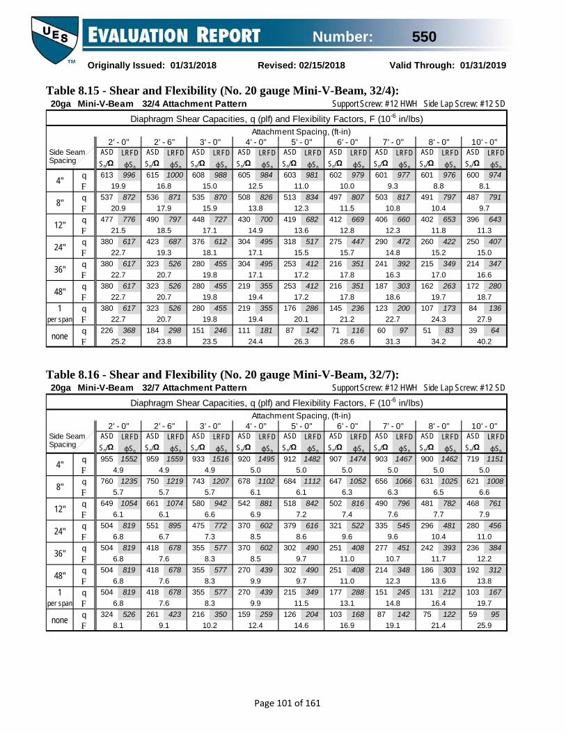
Number: 550
Originally Issued: 01/31/2018 Revised: 02/15/2018 Valid Through: 01/31/2019
Page 101 of 161
Table 8.15 - Shear and Flexibility (No. 20 gauge Mini-V-Beam, 32/4):
Table 8.16 - Shear and Flexibility (No. 20 gauge Mini-V-Beam, 32/7):
20ga Mini-V-Beam 32/4 Attachment Pattern Support Screw: #12 HWH Side Lap Screw: #12 SD
ASD Sn/Ω
LRFD φSn
ASD Sn/Ω
LRFD φSn
ASD Sn/Ω
LRFD φSn
ASD Sn/Ω
LRFD φSn
ASD Sn/Ω
LRFD φSn
ASD Sn/Ω
LRFD φSn
ASD Sn/Ω
LRFD φSn
ASD Sn/Ω
LRFD φSn
ASD Sn/Ω
LRFD φSn
q 613 996 615 1000 608 988 605 984 603 981 602 979 601 977 601 976 600 974F q 537 872 536 871 535 870 508 826 513 834 497 807 503 817 491 797 487 791F q 477 776 490 797 448 727 430 700 419 682 412 669 406 660 402 653 396 643F q 380 617 423 687 376 612 304 495 318 517 275 447 290 472 260 422 250 407F q 380 617 323 526 280 455 304 495 253 412 216 351 241 392 215 349 214 347F q 380 617 323 526 280 455 219 355 253 412 216 351 187 303 162 263 172 280F
1 q 380 617 323 526 280 455 219 355 176 286 145 236 123 200 107 173 84 136per span F
q 226 368 184 298 151 246 111 181 87 142 71 116 60 97 51 83 39 64F
Attachment Spacing, (ft-in)Diaphragm Shear Capacities, q (plf) and Flexibility Factors, F (10-6 in/lbs)
40.2
2' - 0" 2' - 6" 3' - 0" 4' - 0" 5' - 0" 6' - 0" 7' - 0" 8' - 0" 10' - 0"
15.0
16.6
18.7
27.9
8.1
9.7
11.3
31.3
8.8
34.2
14.8
16.3
18.6
22.7
9.3
10.8
12.3
10.4
11.8
15.2
17.0
19.7
24.3
26.3
10.0
11.5
12.8
15.7
17.8
17.8
21.2
28.6
15.5
17.2
17.2
20.1
11.0
12.3
13.6
23.5
12.5
13.8
14.9
17.1
17.1
19.4
19.4
24.4
18.1
19.8
19.8
19.8
15.0
15.9
17.1
22.7
25.2
16.8
17.9
18.5
19.3
20.7
20.7
20.7
23.8
21.5
22.7
22.7
22.7
19.9
20.9
none
4"
8"
12"
24"
36"
48"
Side Seam Spacing
20ga Mini-V-Beam 32/7 Attachment Pattern Support Screw: #12 HWH Side Lap Screw: #12 SD
ASD Sn/Ω
LRFD φSn
ASD Sn/Ω
LRFD φSn
ASD Sn/Ω
LRFD φSn
ASD Sn/Ω
LRFD φSn
ASD Sn/Ω
LRFD φSn
ASD Sn/Ω
LRFD φSn
ASD Sn/Ω
LRFD φSn
ASD Sn/Ω
LRFD φSn
ASD Sn/Ω
LRFD φSn
q 955 1552 959 1559 933 1516 920 1495 912 1482 907 1474 903 1467 900 1462 719 1151F q 760 1235 750 1219 743 1207 678 1102 684 1112 647 1052 656 1066 631 1025 621 1008F q 649 1054 661 1074 580 942 542 881 518 842 502 816 490 796 481 782 468 761F q 504 819 551 895 475 772 370 602 379 616 321 522 335 545 296 481 280 456F q 504 819 418 678 355 577 370 602 302 490 251 408 277 451 242 393 236 384F q 504 819 418 678 355 577 270 439 302 490 251 408 214 348 186 303 192 312F
1 q 504 819 418 678 355 577 270 439 215 349 177 288 151 245 131 212 103 167per span F
q 324 526 261 423 216 350 159 259 126 204 103 168 87 142 75 122 59 95F
Attachment Spacing, (ft-in)Diaphragm Shear Capacities, q (plf) and Flexibility Factors, F (10-6 in/lbs)
25.9
2' - 0" 2' - 6" 3' - 0" 4' - 0" 5' - 0" 6' - 0" 7' - 0" 8' - 0" 10' - 0"
11.0
12.2
13.8
19.7
5.0
6.6
7.9
19.1
5.0
21.4
9.6
10.7
12.3
14.8
5.0
6.3
7.6
6.5
7.7
10.4
11.7
13.6
16.4
14.6
5.0
6.3
7.4
9.6
11.0
11.0
13.1
16.9
8.6
9.7
9.7
11.5
5.0
6.1
7.2
10.2
5.0
6.1
6.9
8.5
8.5
9.9
9.9
12.4
7.3
8.3
8.3
8.3
4.9
5.7
6.6
6.8
8.1
4.9
5.7
6.1
6.7
7.6
7.6
7.6
9.1
6.1
6.8
6.8
6.8
4.9
5.7
none
4"
8"
12"
24"
36"
48"
Side Seam Spacing

Number: 550
Originally Issued: 01/31/2018 Revised: 02/15/2018 Valid Through: 01/31/2019
Page 102 of 161
Table 8.17 - Shear and Flexibility (No. 18 gauge Mini-V-Beam, 32/4):
Table 8.18 - Shear and Flexibility (No. 18 gauge Mini-V-Beam, 32/7):
18ga Mini-V-Beam 32/4 Attachment Pattern Support Screw: #12 HWH Side Lap Screw: #12 SD
ASD Sn/Ω
LRFD φSn
ASD Sn/Ω
LRFD φSn
ASD Sn/Ω
LRFD φSn
ASD Sn/Ω
LRFD φSn
ASD Sn/Ω
LRFD φSn
ASD Sn/Ω
LRFD φSn
ASD Sn/Ω
LRFD φSn
ASD Sn/Ω
LRFD φSn
ASD Sn/Ω
LRFD φSn
q 795 1292 798 1297 788 1281 785 1275 782 1271 781 1269 780 1267 779 1266 778 1263F q 696 1131 695 1129 694 1128 659 1071 666 1082 644 1047 652 1059 636 1034 631 1026F q 619 1006 636 1033 580 943 558 907 544 884 534 868 527 856 521 847 513 834F q 493 801 548 891 488 793 395 641 413 671 357 580 376 611 337 547 325 527F q 493 801 419 682 363 590 395 641 328 534 280 455 313 509 278 452 277 450F q 493 801 419 682 363 590 283 460 328 534 280 455 243 395 212 344 225 365F
1 q 493 801 419 682 363 590 283 460 230 373 190 308 161 262 140 227 110 178per span F
q 293 477 239 389 198 321 146 237 115 186 94 152 79 128 68 110 52 85F
Attachment Spacing, (ft-in)Diaphragm Shear Capacities, q (plf) and Flexibility Factors, F (10-6 in/lbs)
33.9
2' - 0" 2' - 6" 3' - 0" 4' - 0" 5' - 0" 6' - 0" 7' - 0" 8' - 0" 10' - 0"
11.8
13.1
15.0
23.1
5.7
7.1
8.5
25.6
6.0
28.3
11.1
12.4
14.5
18.0
6.3
7.6
8.9
7.5
8.7
11.7
13.2
15.6
19.6
20.6
6.7
8.0
9.1
11.7
13.5
13.5
16.5
23.0
11.1
12.6
12.6
15.1
7.2
8.3
9.5
16.7
7.9
9.1
10.0
12.0
12.0
14.0
14.0
18.4
11.9
13.4
13.4
13.4
9.2
10.0
11.0
14.2
16.4
10.1
11.1
11.5
12.3
13.5
13.5
13.5
16.3
13.2
14.2
14.2
14.2
11.7
12.6
none
4"
8"
12"
24"
36"
48"
Side Seam Spacing
18ga Mini-V-Beam 32/7 Attachment Pattern Support Screw: #12 HWH Side Lap Screw: #12 SD
ASD Sn/Ω
LRFD φSn
ASD Sn/Ω
LRFD φSn
ASD Sn/Ω
LRFD φSn
ASD Sn/Ω
LRFD φSn
ASD Sn/Ω
LRFD φSn
ASD Sn/Ω
LRFD φSn
ASD Sn/Ω
LRFD φSn
ASD Sn/Ω
LRFD φSn
ASD Sn/Ω
LRFD φSn
q 1239 2013 1244 2021 1209 1965 1193 1939 1183 1922 1176 1911 1171 1902 1167 1896 1069 1710F q 986 1602 972 1580 963 1565 880 1429 887 1441 839 1364 851 1382 818 1329 805 1308F q 841 1367 857 1392 752 1222 703 1142 672 1092 651 1058 635 1033 624 1014 607 987F q 653 1062 714 1160 616 1002 480 780 492 799 417 677 435 706 384 624 364 592F q 653 1062 541 880 460 748 480 780 391 636 327 532 361 586 315 512 307 499F q 653 1062 541 880 460 748 352 572 391 636 327 532 279 453 243 395 250 406F
1 q 653 1062 541 880 460 748 352 572 280 454 231 376 197 320 171 278 135 219per span F
q 420 682 339 551 281 457 208 338 165 267 135 220 115 186 99 161 77 125F
Attachment Spacing, (ft-in)Diaphragm Shear Capacities, q (plf) and Flexibility Factors, F (10-6 in/lbs)
22.4
2' - 0" 2' - 6" 3' - 0" 4' - 0" 5' - 0" 6' - 0" 7' - 0" 8' - 0" 10' - 0"
9.3
10.4
11.8
16.9
4.1
5.4
6.6
16.4
4.0
18.4
8.0
9.0
10.4
12.6
4.0
5.2
6.3
5.3
6.4
8.8
9.9
11.5
14.0
12.5
4.0
5.2
6.1
8.1
9.3
9.3
11.2
14.4
7.2
8.2
8.2
9.7
4.0
5.0
5.9
8.5
4.0
4.9
5.7
7.0
7.0
8.3
8.3
10.5
6.0
6.9
6.9
6.9
3.9
4.6
5.3
5.5
6.6
3.8
4.6
4.9
5.4
6.2
6.2
6.2
7.6
4.9
5.5
5.5
5.5
3.8
4.5
none
4"
8"
12"
24"
36"
48"
Side Seam Spacing

Number: 550
Originally Issued: 01/31/2018 Revised: 02/15/2018 Valid Through: 01/31/2019
Page 103 of 161
9.0 Nor-Clad® Figure 9.1 - Basic Dimensions and Panel Attachment (Nor-Clad):
36/4 Pattern:
36/8 Pattern:
Table 9.1 - Section Properties (Nor-Clad):
Area Moment of Inertia
Distance to N.A. from
Bottom
Positive Section
Modulus
Negative Section
Modulusw t Fy Fu Ag Ig yb Sg+ Sg-
psf in ksi ksi in2/ft in4/ft in in3/ft in3/ft29 0.65 0.0139 80 82 0.1912 0.0080 0.15 0.0164 0.053926 0.81 0.0173 80 82 0.2380 0.0100 0.15 0.0204 0.0663
Moment of Inertia
Distance to N.A. from
Bottom
Section Modulus
Moment of Inertia
Distance to N.A. from
Bottom
Section Modulus
Ae/ft Ie+ yb Se+ Ie- yb Se- I+ I-
in2 in4/ft in in3/ft in4/ft in in3/ft in4/ft in4/ft29 0.0259 0.0080 0.14 0.0147 0.0057 0.30 0.0149 0.0080 0.006426 0.0360 0.0100 0.15 0.0195 0.0097 0.30 0.0188 0.0100 0.0098
Gauge Weight Base Metal Thickness
Yield Strength
Tensile Strength
Gross Section Properties
Gauge
Effective Section Properties Uniform Load Only
Area
Positive Negative
Id = (2Ie+Ig)/3

Number: 550
Originally Issued: 01/31/2018 Revised: 02/15/2018 Valid Through: 01/31/2019
Page 104 of 161
Table 9.2 - Inward (Positive) Uniform Allowable Loads (Nor-Clad): Gauge Span Limit
Condition Panel Span (Support Spacing)
16" 2' - 0" 2' - 6" 3' - 0" 3' - 6" 4' - 0" 4' - 6" 5' - 0" 6' - 0"
29
Single Span
ASD, W/Ω LRFD, φW
199 316
88 140
56 89
39 62
29 46
22 35
17 28
14 22
10 16
L/240 L/180 L/120
- - -
66 87 -
34 45 -
19 26 39
12 16 24
8 11 16
6 8 12
4 6 8
2 3 5
Double Span
ASD, W/Ω LRFD, φW
196 296
88 132
57 85
39 59
28 43
22 33
17 26
13 21
9 14
L/240 L/180 L/180
- - -
- - -
- - -
- - -
- - -
20 - -
14 - -
10 - -
6 8 8
Triple Span
ASD, W/Ω LRFD, φW
243 366
110 165
70 106
49 73
36 54
27 41
21 32
18 27
12 19
L/240 L/180 L/120
- - -
- - -
63 - -
37 49 -
23 31 -
15 21 -
11 14 -
8 11 16
5 6 9
26
Single Span
ASD, W/Ω LRFD, φW
264 418
117 185
75 118
52 82
38 60
29 46
23 37
19 30
13 21
L/240 L/180 L/120
- - -
82 109
-
42 56 -
24 32 49
15 20 31
10 14 20
7 10 14
5 7 10
3 4 6
Double Span
ASD, W/Ω LRFD, φW
248 373
111 167
71 107
50 75
36 54
28 42
22 33
17 26
12 18
L/240 L/180 L/120
- - -
- - -
- - -
- - -
- - -
25 - -
17 - -
13 17 -
7 10 -
Triple Span
ASD, W/Ω LRFD, φW
307 462
138 208
89 134
61 93
45 68
34 52
27 41
22 34
15 23
L/240 L/180 L/120
- - -
- - -
79 - -
46 61 -
29 38 -
19 26 -
14 18 -
10 13 20
6 8 11
Table 9.3 - Allowable Reactions at Supports (Nor-Clad):
Reactions at Supports based on Web Crippling
Gauge
Condition
Bearing Length of Webs ASD (Pn/Ω) (lbs/ft width) LRFD (φPn) (lbs/ft width)
1" 1.5" 1" 1.5"
29 End Interior
123 162
142 184
188 241
217 273
26 End Interior
184 251
211 283
281 373
323 420

Number: 550
Originally Issued: 01/31/2018 Revised: 02/15/2018 Valid Through: 01/31/2019
Page 105 of 161
Table 9.4 - Outward (Negative) Uniform Allowable Loads (No. 29 gauge Nor-Clad):
Thick- ness
ASD W/Ω
ASD W/Ω
ASD W/Ω
ASD W/Ω
ASD W/Ω
ASD W/Ω
ASD W/Ω
ASD W/Ω
ASD W/Ω
#12 36/8 330 147 94 65 48 37 29 23 15#12 36/4 285 147 94 65 48 37 29 23 15#12 36/8 330 147 94 65 48 37 29 23 15#12 36/4 285 147 94 65 48 37 29 23 15#12 36/8 330 147 94 65 48 37 29 23 15#12 36/4 278 147 94 65 48 37 29 23 15#12 36/8 330 147 94 65 48 37 29 23 15#12 36/4 235 147 94 65 48 37 29 23 15#12 36/8 330 147 94 65 48 37 29 23 15#12 36/4 183 122 94 65 48 37 29 23 15#12 36/8 282 147 94 65 48 37 29 23 15#12 36/4 141 94 75 63 48 37 29 23 15#12 36/8 234 147 94 65 48 37 29 23 15#12 36/4 117 78 62 52 45 37 29 23 15#12 36/8 330 147 94 65 48 37 29 23 15#12 36/4 285 147 94 65 48 37 29 23 15#12 36/8 330 147 94 65 48 37 29 23 15#12 36/4 285 147 94 65 48 37 29 23 15#12 36/8 330 147 94 65 48 37 29 23 15#12 36/4 193 129 94 65 48 37 29 23 15#12 36/8 325 147 94 65 48 37 29 23 15#12 36/4 162 108 87 65 48 37 29 23 15#12 36/8 253 147 94 65 48 37 29 23 15#12 36/4 126 84 67 56 48 37 29 23 15#12 36/8 195 130 94 65 48 37 29 23 15#12 36/4 97 65 52 43 37 32 29 23 15#12 36/8 162 108 86 65 48 37 29 23 15#12 36/4 81 54 43 36 31 27 24 22 15#14 36/8 209 140 94 65 48 37 29 23 15#14 36/4 105 70 56 47 40 35 29 23 15#14 36/8 265 147 94 65 48 37 29 23 15#14 36/4 133 88 71 59 48 37 29 23 15#14 36/8 321 147 94 65 48 37 29 23 15#14 36/4 161 107 86 65 48 37 29 23 15#9 36/8 330 147 94 65 48 37 29 23 15#9 36/4 194 129 94 65 48 37 29 23 15
#14 36/8 330 147 94 65 48 37 29 23 15#14 36/4 265 147 94 65 48 37 29 23 15
74 5074
2615
74
26
2615
50 35
1515
262626
50
74
15
26 15
1526
35
3550 35 26
151515
50
15
74 5050 35 26
3535
523 233 149
434 233
103
103
217 145 116149 103
96
189
233179 119
26
26283141 94 75
35
26149
68 5035
47
35
63 54358
96 8074
15149 103 74 50
263515
103149149
1515
5050
7474
50
94 2635
35
78
524358
233233
149149
103103
7474
5050
3535
2626
1515
50 35
3550
26 1535 26
15
262 103 74 50
50
175
15103 74 50
26 15
103
35
3550
67
26 1535
35 26 15
50
274524 233 149 103
183 146 103 7435 26
2626
2626103
3535
418103
74352 233 149524 233 149
233 149
Nor-Clad, 29ga
Substrate
Fastener
Nom. Size
Attach.Pattern
103 74 50 35 26 15
Material/ Grade
Steel(Gr 50 min.)
524 233 149
149 103
103
747474
149 103
Panel System Negative (Outward) Uniform Load Capacity, (lbs/ft2)
141233
113149
94
LRFD φW
LRFD φW
LRFD φW
LRFD φW
LRFD φW
LRFD φW
LRFD φW
LRFD φW
LRFD φW
Attachment Spacing, (ft-in)
5050
35
427 74
15
35
22ga (.0294")
16" 2' - 0" 2' - 6" 3' - 0" 3' - 6"
351211422
233
≥10ga (.1350")
14ga (.0700")
16ga (.0590")
18ga (.0459")
12ga (.1050")
20ga (.0354")
74524 233
524427
233233
117
4' - 0"
50
233 149 103
15427 233 149 103 74 50
149 103 74 50 35
4' - 6" 5' - 0" 6' - 0"
26 1550
26
12ga (.1050")
524 233 149 103 74
16ga (.0590")
487 233 149 103 74
14ga (.0700")
244 162 130 103 74
289 193 149 103 74524 233 149 103 74 50
103 74
12135
50 3535
190 126 101 84 72 50 35
Steel(Gr 33 min.)
15
233
15
22ga (.0294")
243 162 130 103 74 50
50 35146 97 78 65
18ga (.0459")
379 233 149 103 74 50
15/32"
1515
26 15
1515
26 15
81 65 54 46 40 35
35 2626
56 4920ga
(.0354")292 195 149
19/32"
23/32"
1" min
Plywood & OSB
Lumber(DFL)
140174
26 15427 233 149 103 74 50 35 26
26 15
≥10ga (.1350")
524
1535 26

Number: 550
Originally Issued: 01/31/2018 Revised: 02/15/2018 Valid Through: 01/31/2019
Page 106 of 161
Table 9.5 - Outward (Negative) Uniform Allowable Loads (No. 26 gauge Nor-Clad):
Thick- ness
ASD W/Ω
ASD W/Ω
ASD W/Ω
ASD W/Ω
ASD W/Ω
ASD W/Ω
ASD W/Ω
ASD W/Ω
ASD W/Ω
#12 36/8 437 194 124 86 63 49 38 31 22#12 36/4 355 194 124 86 63 49 38 31 22#12 36/8 437 194 124 86 63 49 38 31 22#12 36/4 355 194 124 86 63 49 38 31 22#12 36/8 437 194 124 86 63 49 38 31 22#12 36/4 278 186 124 86 63 49 38 31 22#12 36/8 437 194 124 86 63 49 38 31 22#12 36/4 235 156 124 86 63 49 38 31 22#12 36/8 365 194 124 86 63 49 38 31 22#12 36/4 183 122 97 81 63 49 38 31 22#12 36/8 282 188 124 86 63 49 38 31 22#12 36/4 141 94 75 63 54 47 38 31 22#12 36/8 234 156 124 86 63 49 38 31 22#12 36/4 117 78 62 52 45 39 35 31 22#12 36/8 437 194 124 86 63 49 38 31 22#12 36/4 355 194 124 86 63 49 38 31 22#12 36/8 437 194 124 86 63 49 38 31 22#12 36/4 289 193 124 86 63 49 38 31 22#12 36/8 386 194 124 86 63 49 38 31 22#12 36/4 193 129 103 86 63 49 38 31 22#12 36/8 325 194 124 86 63 49 38 31 22#12 36/4 162 108 87 72 62 49 38 31 22#12 36/8 253 169 124 86 63 49 38 31 22#12 36/4 126 84 67 56 48 42 37 31 22#12 36/8 195 130 104 86 63 49 38 31 22#12 36/4 97 65 52 43 37 32 29 26 22#12 36/8 162 108 86 72 62 49 38 31 22#12 36/4 81 54 43 36 31 27 24 22 18#14 36/8 209 140 112 86 63 49 38 31 22#14 36/4 105 70 56 47 40 35 31 28 22#14 36/8 265 177 124 86 63 49 38 31 22#14 36/4 133 88 71 59 51 44 38 31 22#14 36/8 321 194 124 86 63 49 38 31 22#14 36/4 161 107 86 71 61 49 38 31 22#9 36/8 388 194 124 86 63 49 38 31 22#9 36/4 194 129 103 86 63 49 38 31 22
#14 36/8 437 194 124 86 63 49 38 31 22#14 36/4 265 177 124 86 63 49 38 31 22
101 7683
3922
101
39
3922
76 53
2222
393939
58
101
22
39 22
2239
53
5376 53 39
222222
76
22
101 7676 53 39
5353
523 308 197
434 289
137
137
217 145 116197 137
96
189
239179 119
39
39283141 94 75
53
39191
68 6053
47
53
63 54358
96 80101
22151 126 101 76
384222
137197197
2222
7676
101101
76
94 3952
53
78
694358
308238
197191
137137
101101
7676
5353
3939
2222
76 53
5372
39 2253 39
22
262 116 100 76
76
175
22137 101 76
39 22
137
53
5376
67
39 2253
53 39 22
76
274548 308 197 137
183 146 122 10153 39
3939
3939137
5353
418137
101352 235 188694 308 197
278 197
Nor-Clad, 26ga
Substrate
Fastener
Nom. Size
Attach.Pattern
137 101 76 53 39 22
Material/ Grade
Steel(Gr 50 min.)
694 308 197
187 137
137
10180
101
197 137
Panel System Negative (Outward) Uniform Load Capacity, (lbs/ft2)
141282
113197
94
LRFD φW
LRFD φW
LRFD φW
LRFD φW
LRFD φW
LRFD φW
LRFD φW
LRFD φW
LRFD φW
Attachment Spacing, (ft-in)
7670
53
532 101
22
53
22ga (.0294")
16" 2' - 0" 2' - 6" 3' - 0" 3' - 6"
351211422
234
≥10ga (.1350")
14ga (.0700")
16ga (.0590")
18ga (.0459")
12ga (.1050")
20ga (.0354")
101694 308
694532
308308
117
4' - 0"
76
308 197 137
22434 289 197 137 101 76
197 137 101 76 53
4' - 6" 5' - 0" 6' - 0"
39 2276
39
12ga (.1050")
694 308 197 137 101
16ga (.0590")
487 308 197 137 101
14ga (.0700")
244 162 130 108 93
289 193 154 129 101578 308 197 137 101 76
130 101
12153
76 5353
190 126 101 84 72 63 53
Steel(Gr 33 min.)
22
308
22
22ga (.0294")
243 162 130 108 93 76
76 53146 97 78 65
18ga (.0459")
379 253 197 137 101 76
15/32"
2222
39 22
2222
39 22
81 65 54 46 40 36
43 3939
56 4920ga
(.0354")292 195 156
19/32"
23/32"
1" min
Plywood & OSB
Lumber(DFL)
140174
39 22532 308 197 137 101 76 53 39
32 22
≥10ga (.1350")
694
2253 39

Number: 550
Originally Issued: 01/31/2018 Revised: 02/15/2018 Valid Through: 01/31/2019
Page 107 of 161
Table 9.6 - Shear and Flexibility (No. 29 gauge Nor-Clad, 36/4):
Table 9.7 - Shear and Flexibility (No. 26 gauge Nor-Clad, 36/4):
Note: Shear Tables 9.6 & 9.7 based on 36/4 attachment pattern. Values acceptable for use (conservative) for 36/8 attachment pattern.
29ga Nor-Clad 36/4 Attachment Pattern Support Screw: #12 HWH Side Lap Screw: #12 SD
ASD Sn/Ω
LRFD φSn
ASD Sn/Ω
LRFD φSn
ASD Sn/Ω
LRFD φSn
ASD Sn/Ω
LRFD φSn
ASD Sn/Ω
LRFD φSn
ASD Sn/Ω
LRFD φSn
ASD Sn/Ω
LRFD φSn
ASD Sn/Ω
LRFD φSn
ASD Sn/Ω
LRFD φSn
q 326 529 323 525 324 527 321 522 323 524 263 420 208 332 168 269 117 187F q 295 480 286 465 286 465 287 466 287 466 263 420 208 332 168 269 117 187F q 295 480 255 414 263 428 242 393 251 408 234 381 208 332 168 269 117 187F q 253 411 201 326 227 369 203 330 183 297 165 269 189 307 168 269 117 187F q 253 411 201 326 171 279 148 241 183 297 165 269 151 245 138 224 117 187F q 253 411 201 326 171 279 148 241 130 212 116 189 151 245 138 224 117 187F
1 q 253 411 201 326 171 279 148 241 130 212 116 189 104 170 95 154 78 127per span F
q 156 254 111 180 89 145 74 120 63 102 54 88 48 78 43 70 35 57F
Attachment Spacing, (ft-in)Diaphragm Shear Capacities, q (plf) and Flexibility Factors, F (10-6 in/lbs)
41.7
16" 2' - 0" 2' - 6" 3' - 0" 3' - 6" 4' - 0" 4' - 6" 5' - 0" 6' - 0"
19.8
23.0
23.0
28.7
11.2
13.4
15.4
34.0
11.5
36.5
17.6
20.0
20.0
24.3
11.7
13.7
15.1
13.4
15.5
18.3
21.0
21.0
25.7
29.2
12.0
14.0
15.7
19.1
19.1
22.9
22.9
31.6
18.3
18.3
21.6
21.6
12.3
13.9
15.3
25.0
12.9
14.3
16.1
17.6
20.5
20.5
20.5
27.0
17.2
19.5
19.5
19.5
13.4
15.0
15.9
19.5
22.4
14.6
16.0
17.1
19.0
19.0
19.0
19.0
23.3
18.3
19.5
19.5
19.5
17.1
18.3
none
4"
8"
12"
24"
36"
48"
Side Seam Spacing
26ga Nor-Clad 36/4 Attachment Pattern Support Screw: #12 HWH Side Lap Screw: #12 SD
ASD Sn/Ω
LRFD φSn
ASD Sn/Ω
LRFD φSn
ASD Sn/Ω
LRFD φSn
ASD Sn/Ω
LRFD φSn
ASD Sn/Ω
LRFD φSn
ASD Sn/Ω
LRFD φSn
ASD Sn/Ω
LRFD φSn
ASD Sn/Ω
LRFD φSn
ASD Sn/Ω
LRFD φSn
q 405 659 402 654 404 656 400 650 401 652 366 586 289 463 234 375 163 260F q 368 597 356 578 356 579 357 580 357 580 341 554 289 463 234 375 163 260F q 368 597 317 516 328 533 301 489 312 507 292 474 289 463 234 375 163 260F q 315 511 250 406 283 460 253 411 227 370 206 335 235 382 218 354 163 260F q 315 511 250 406 213 347 185 300 227 370 206 335 188 305 172 279 147 239F q 315 511 250 406 213 347 185 300 162 264 145 235 188 305 172 279 147 239F
1 q 315 511 250 406 213 347 185 300 162 264 145 235 130 211 118 192 98 159per span F
q 194 316 138 224 112 182 92 150 79 128 68 111 60 98 54 87 44 72F
Attachment Spacing, (ft-in)Diaphragm Shear Capacities, q (plf) and Flexibility Factors, F (10-6 in/lbs)
36.1
16" 2' - 0" 2' - 6" 3' - 0" 3' - 6" 4' - 0" 4' - 6" 5' - 0" 6' - 0"
16.5
19.4
19.4
24.5
8.8
10.8
12.5
29.1
9.0
31.4
14.4
16.5
16.5
20.3
9.1
10.9
12.1
10.7
12.5
15.1
17.5
17.5
21.7
24.6
9.3
11.1
12.5
15.6
15.6
19.0
19.0
26.8
14.8
14.8
17.7
17.7
9.4
10.8
12.1
20.3
9.7
11.1
12.6
14.0
16.6
16.6
16.6
22.4
13.4
15.5
15.5
15.5
10.0
11.4
12.2
14.2
16.8
10.7
12.0
12.9
14.6
14.6
14.6
14.6
18.5
13.1
14.2
14.2
14.2
12.1
13.1
none
4"
8"
12"
24"
36"
48"
Side Seam Spacing

Number: 550
Originally Issued: 01/31/2018 Revised: 02/15/2018 Valid Through: 01/31/2019
Page 108 of 161
10.0 Nu-Wave® Corrugated Figure 10.1 - Basic Dimensions and Panel Attachment (Nu-Wave Corrugated):
32/5 Pattern: (roof / wall)
32/7 Pattern: (roof / wall)
34.7/5 Pattern: (wall)
34.7/7 Pattern: (wall)

Number: 550
Originally Issued: 01/31/2018 Revised: 02/15/2018 Valid Through: 01/31/2019
Page 109 of 161
Table 10.1 - Section Properties (Nu-Wave Corrugated):
Area Moment of Inertia
Distance to N.A. from
Bottom
Positive Section
Modulus
Negative Section
Modulusw t Fy Fu Ag Ig yb Sg+ Sg-
psf in ksi ksi in2/ft in4/ft in in3/ft in3/ft26 0.94 0.0173 80 82 0.2749 0.0256 0.44 0.0579 0.057924 1.25 0.0232 50 65 0.3682 0.0346 0.44 0.0769 0.076922 1.59 0.0294 50 65 0.4661 0.0415 0.45 0.0964 0.096420 1.91 0.0354 40 55 0.5606 0.0519 0.45 0.1150 0.1150
Moment of Inertia
Distance to N.A. from
Bottom
Section Modulus
Moment of Inertia
Distance to N.A. from
Bottom
Section Modulus
Ae/ft Ie+ yb Se+ Ie- yb Se- I+ I-
in2 in4/ft in in3/ft in4/ft in in3/ft in4/ft in4/ft
26 0.2117 0.0256 0.44 0.0579 0.0256 0.44 0.0579 0.0256 0.025624 0.3369 0.0346 0.45 0.0769 0.0346 0.45 0.0769 0.0346 0.034622 0.4589 0.0415 0.43 0.0964 0.0415 0.43 0.0964 0.0415 0.041520 0.5550 0.0519 0.45 0.1150 0.0519 0.45 0.1150 0.0519 0.0519
Gauge
Effective Section Properties Uniform Load Only
Area
Positive Negative
Id = (2Ie+Ig)/3
Gauge Weight Base Metal Thickness
Yield Strength
Tensile Strength
Gross Section Properties

Number: 550
Originally Issued: 01/31/2018 Revised: 02/15/2018 Valid Through: 01/31/2019
Page 110 of 161
Table 10.2 - Inward (Positive) Uniform Allowable Loads (Nu-Wave Corrugated): Gauge Span Limit
Condition Panel Span (Support Spacing)
2' - 0" 2' - 6" 3' - 0" 3' - 6" 4' - 0" 5' - 0" 6' - 0" 7' - 0" 8' - 0"
26
Single Span
ASD, W/Ω LRFD, φW
347 550
222 352
154 244
113 180
87 137
55 88
39 61
28 45
22 34
L/240 L/180 L/120
210 280
-
107 143 215
62 83 124
39 52 78
26 35 52
13 18 27
8 10 16
5 7 10
3 4 7
Double Span
ASD, W/Ω LRFD, φW
334 503
217 326
151 227
111 168
85 128
55 83
38 57
28 42
21 32
L/240 L/180 L/120
- - -
- - -
150 - -
94 - -
63 84 -
32 43 -
19 25 37
12 16 24
8 11 16
Triple Span
ASD, W/Ω LRFD, φW
411 619
268 403
188 282
138 208
106 160
69 103
47 71
35 53
27 41
L/240 L/180 L/120
396 - -
203 - -
117 156
-
74 99 -
50 66 99
25 34 51
15 20 29
9 12 18
6 8 12
24
Single Span
ASD, W/Ω LRFD, φW
384 609
246 390
171 271
125 199
96 152
61 97
43 68
31 50
24 38
L/240 L/180 L/120
284 378
-
145 194
-
84 112 168
53 71 106
35 47 71
18 24 36
11 14 21
7 9 13
4 6 9
Double Span
ASD, W/Ω LRFD, φW
370 556
239 360
167 252
123 186
95 143
60 91
42 64
31 46
23 35
L/240 L/180 L/120
- - -
- - -
- - -
- - -
85 - -
44 58 -
25 34 -
16 21 -
11 14 21
Triple Span
ASD, W/Ω LRFD, φW
455 685
297 446
208 313
154 231
118 177
75 114
52 79
39 58
30 45
L/240 L/180 L/120
- - -
274 - -
159 - -
100 133
-
67 89 -
34 46 69
20 26 40
12 17 25
8 11 17
22
Single Span
ASD, W/Ω LRFD, φW
481 763
308 488
214 339
157 249
120 191
77 122
53 85
39 62
30 48
L/240 L/180 L/120
340 454
-
174 232
-
101 134 202
64 85 127
43 57 85
22 29 44
13 17 25
8 11 16
5 7 11
Double Span
ASD, W/Ω LRFD, φW
463 697
300 452
210 316
154 232
119 179
76 115
53 80
39 59
29 44
L/240 L/180 L/120
- - -
- - -
- - -
153 - -
102 - -
52 70 -
30 40 -
19 25 38
13 17 26
Triple Span
ASD, W/Ω LRFD, φW
571 859
371 559
261 392
193 290
148 223
95 143
65 99
48 72
37 55
L/240 L/180 L/120
- - -
329 - -
190 254
-
120 160
-
80 107
-
41 55 82
24 32 48
15 20 30
10 13 20

Number: 550
Originally Issued: 01/31/2018 Revised: 02/15/2018 Valid Through: 01/31/2019
Page 111 of 161
Table 10.2 (Cont’d) - Inward (Positive) Uniform Allowable Loads (Nu-Wave Corrugated) Gauge Span Limit
Condition Panel Span (Support Spacing)
2' - 0" 2' - 6" 3' - 0" 3' - 6" 4' - 0" 5' - 0" 6' - 0" 7' - 0" 8' - 0"
20
Single Span
ASD, W/Ω LRFD, φW
459 728
294 466
204 324
150 238
115 182
73 116
51 81
37 59
29 46
L/240 L/180 L/120
425 - -
218 290
-
126 168
-
79 106
-
53 71 106
27 36 54
16 21 32
10 13 20
7 9 13
Double Span
ASD, W/Ω LRFD, φW
442 665
286 431
201 302
148 222
114 171
72 109
50 75
37 55
28 42
L/240 L/180 L/120
- - -
- - -
- - -
- - -
- - -
66 - -
38 - -
24 32 -
16 21 -
Triple Span
ASD, W/Ω LRFD, φW
544 819
354 533
248 374
184 276
141 212
91 137
63 95
46 70
35 53
L/240 L/180 L/120
- - -
- - -
238 - -
150 - -
100 134
-
51 69 -
30 40 59
19 25 37
13 17 25
Table 10.3 - Allowable Reactions at Supports (Nu-Wave Corrugated):
Reactions at Supports based on Web Crippling
Gauge
Condition
Bearing Length of Webs ASD (Pn/Ω) (lbs/ft width) LRFD (φPn) (lbs/ft width)
1.5" 1.5"
26 End Interior
509 711
815 1138
24 End Interior
540 879
864 1408
22 End Interior
836 1406
1339 2251
20 End Interior
1118 2062
1791 3301

Number: 550
Originally Issued: 01/31/2018 Revised: 02/15/2018 Valid Through: 01/31/2019
Page 112 of 161
Table 10.4 - Outward (Negative) Uniform Allowable Loads (No. 26 gauge Nu-Wave
Corrugated):
Note: Load table above based on 34.7” installation coverage. Values acceptable for use (conservative) for 32” installation coverage.
Thick- ness
ASD W/Ω
ASD W/Ω
ASD W/Ω
ASD W/Ω
ASD W/Ω
ASD W/Ω
ASD W/Ω
ASD W/Ω
ASD W/Ω
#12 34.7/7 430 344 257 189 144 92 59 37 25#12 34.7/5 307 246 205 175 144 92 59 37 25#12 34.7/7 430 344 257 189 144 92 59 37 25#12 34.7/5 307 246 205 175 144 92 59 37 25#12 34.7/7 337 270 225 189 144 92 59 37 25#12 34.7/5 241 193 161 138 120 92 59 37 25#12 34.7/7 284 227 190 162 142 92 59 37 25#12 34.7/5 203 162 135 116 102 81 59 37 25#12 34.7/7 221 177 147 126 111 88 59 37 25#12 34.7/5 158 126 105 90 79 63 53 37 25#12 34.7/7 171 136 114 97 85 68 57 37 25#12 34.7/5 122 97 81 70 61 49 41 35 25#12 34.7/7 142 113 94 81 71 57 47 37 25#12 34.7/5 101 81 67 58 51 40 34 29 25#12 34.7/7 430 344 257 189 144 92 59 37 25#12 34.7/5 307 246 205 175 144 92 59 37 25#12 34.7/7 350 280 234 189 144 92 59 37 25#12 34.7/5 250 200 167 143 125 92 59 37 25#12 34.7/7 234 187 156 133 117 92 59 37 25#12 34.7/5 167 133 111 95 83 67 56 37 25#12 34.7/7 197 157 131 112 98 79 59 37 25#12 34.7/5 141 112 94 80 70 56 47 37 25#12 34.7/7 153 123 102 88 77 61 51 37 25#12 34.7/5 109 88 73 63 55 44 36 31 25#12 34.7/7 118 94 79 67 59 47 39 34 25#12 34.7/5 84 67 56 48 42 34 28 24 21#12 34.7/7 98 78 65 56 49 39 33 28 25#12 34.7/5 70 56 47 40 35 28 23 20 18#14 34.7/7 127 102 85 73 63 51 42 36 25#14 34.7/5 91 73 60 52 45 36 30 26 23#14 34.7/7 161 129 107 92 80 64 54 37 25#14 34.7/5 115 92 77 66 57 46 38 33 25#14 34.7/7 195 156 130 111 97 78 59 37 25#14 34.7/5 139 111 93 79 69 56 46 37 25#9 34.7/7 235 188 157 134 117 92 59 37 25#9 34.7/5 168 134 112 96 84 67 56 37 25
#14 34.7/7 321 257 214 183 144 92 59 37 25#14 34.7/5 229 183 153 131 115 92 59 37 25
158 10194
3725
131
37
3725
101 59
2525
373737
61
198
25
37 25
2537
59
59100 59 37
252525
101
25
152 101101 59 37
5959
317 254 211
263 210
181
124
188 150 125175 150
107
137
174155 124
37
37171122 98 82
57
37145
77 6259
49
52
70 61217
103 89108
25114 98 86 69
354125
296407307
2525
101101
198198
101
101 3751
59
87
433310
347248
289206
248177
198155
101101
5959
3737
2525
101 59
5975
37 2559 37
25
226 129 113 91
95
152
25207 181 101
37 25
174
59
59101
76
37 2559
59 37 25
87
237332 265 221 190
190 158 135 11859 37
3737
3737263
5959
361244
166305 244 203426 341 284
289 241
Nu-Wave Corrugated, 26ga
Substrate
Fastener
Nom. Size
Attach.Pattern
296 198 101 59 37 25
Material/ Grade
Steel(Gr 50 min.)
644 516 407
142 121
146
10691
128
337 289
Panel System Negative (Outward) Uniform Load Capacity, (lbs/ft2)
146205
122171
104
LRFD φW
LRFD φW
LRFD φW
LRFD φW
LRFD φW
LRFD φW
LRFD φW
LRFD φW
LRFD φW
Attachment Spacing, (ft-in)
10173
59
460 198
25
59
22ga (.0294")
2' - 0" 2' - 6" 3' - 0" 3' - 6" 4' - 0"
213183256
170
≥10ga (.1350")
14ga (.0700")
16ga (.0590")
18ga (.0459")
12ga (.1050")
20ga (.0354")
198506 405
644460
516368
121
5' - 0"
85
368 307 263
25375 300 250 214 188 101
407 296 198 101 59
6' - 0" 7' - 0" 8' - 0"
37 25101
37
12ga (.1050")
525 420 350 296 198
16ga (.0590")
295 236 197 169 148
14ga (.0700")
211 169 141 121 105
250 200 167 143 125350 280 234 200 175 101
101 89
10549
84 5959
164 131 109 94 82 66 55
Steel(Gr 33 min.)
25
516
25
22ga (.0294")
147 118 98 84 74 59
71 59127 101 84 72
18ga (.0459")
230 184 153 131 115 92
15/32"
2525
37 25
2525
37 25
84 70 60 53 42 35
42 3637
63 5120ga
(.0354")177 142 118
19/32"
23/32"
1" min
Plywood & OSB
Lumber(DFL)
151181
37 25460 368 307 263 198 101 59 37
30 25
≥10ga (.1350")
644
2559 37

Number: 550
Originally Issued: 01/31/2018 Revised: 02/15/2018 Valid Through: 01/31/2019
Page 113 of 161
Table 10.5 - Outward (Negative) Uniform Allowable Loads (No. 24 gauge Nu-Wave
Corrugated):
Note: Load table above based on 34.7” installation coverage. Values acceptable for use (conservative) for 32” installation coverage.
Thick- ness
ASD W/Ω
ASD W/Ω
ASD W/Ω
ASD W/Ω
ASD W/Ω
ASD W/Ω
ASD W/Ω
ASD W/Ω
ASD W/Ω
#12 34.7/7 457 307 213 157 120 77 53 39 30#12 34.7/5 326 261 213 157 120 77 53 39 30#12 34.7/7 457 307 213 157 120 77 53 39 30#12 34.7/5 326 261 213 157 120 77 53 39 30#12 34.7/7 337 270 213 157 120 77 53 39 30#12 34.7/5 241 193 161 138 120 77 53 39 30#12 34.7/7 284 227 190 157 120 77 53 39 30#12 34.7/5 203 162 135 116 102 77 53 39 30#12 34.7/7 221 177 147 126 111 77 53 39 30#12 34.7/5 158 126 105 90 79 63 53 39 30#12 34.7/7 171 136 114 97 85 68 53 39 30#12 34.7/5 122 97 81 70 61 49 41 35 30#12 34.7/7 142 113 94 81 71 57 47 39 30#12 34.7/5 101 81 67 58 51 40 34 29 25#12 34.7/7 450 307 213 157 120 77 53 39 30#12 34.7/5 322 257 213 157 120 77 53 39 30#12 34.7/7 350 280 213 157 120 77 53 39 30#12 34.7/5 250 200 167 143 120 77 53 39 30#12 34.7/7 234 187 156 133 117 77 53 39 30#12 34.7/5 167 133 111 95 83 67 53 39 30#12 34.7/7 197 157 131 112 98 77 53 39 30#12 34.7/5 141 112 94 80 70 56 47 39 30#12 34.7/7 153 123 102 88 77 61 51 39 30#12 34.7/5 109 88 73 63 55 44 36 31 27#12 34.7/7 118 94 79 67 59 47 39 34 30#12 34.7/5 84 67 56 48 42 34 28 24 21#12 34.7/7 98 78 65 56 49 39 33 28 25#12 34.7/5 70 56 47 40 35 28 23 20 18#14 34.7/7 127 102 85 73 63 51 42 36 30#14 34.7/5 91 73 60 52 45 36 30 26 23#14 34.7/7 161 129 107 92 80 64 53 39 30#14 34.7/5 115 92 77 66 57 46 38 33 29#14 34.7/7 195 156 130 111 97 77 53 39 30#14 34.7/5 139 111 93 79 69 56 46 39 30#9 34.7/7 235 188 157 134 117 77 53 39 30#9 34.7/5 168 134 112 96 84 67 53 39 30
#14 34.7/7 321 257 213 157 120 77 53 39 30#14 34.7/5 229 183 153 131 115 77 53 39 30
158 12294
5033
131
50
5033
122 79
3333
505047
61
190
33
50 33
3350
79
79100 79 50
333333
118
33
152 122122 79 50
7161
317 254 211
263 210
181
124
188 150 125175 150
107
137
174155 124
50
49171122 98 82
57
44145
77 6272
49
52
70 61217
103 89108
31114 98 86 69
354133
248338326
3333
122122
190190
122
101 4351
79
87
433310
347248
289206
248177
190155
122122
7979
5050
3333
105 79
7975
50 3363 50
33
226 129 113 91
95
152
33207 181 122
50 33
174
79
79122
76
50 3379
75 50 33
87
237332 265 221 190
190 158 135 11879 50
5050
5050248
7979
361244
166305 244 203426 341 284
289 241
Nu-Wave Corrugated, 24ga
Substrate
Fastener
Nom. Size
Attach.Pattern
248 190 122 79 50 33
Material/ Grade
Steel(Gr 50 min.)
685 487 338
142 121
146
10691
128
337 248
Panel System Negative (Outward) Uniform Load Capacity, (lbs/ft2)
146205
122171
104
LRFD φW
LRFD φW
LRFD φW
LRFD φW
LRFD φW
LRFD φW
LRFD φW
LRFD φW
LRFD φW
Attachment Spacing, (ft-in)
10273
79
489 190
33
79
22ga (.0294")
2' - 0" 2' - 6" 3' - 0" 3' - 6" 4' - 0"
213183256
170
≥10ga (.1350")
14ga (.0700")
16ga (.0590")
18ga (.0459")
12ga (.1050")
20ga (.0354")
190506 405
685489
487391
121
5' - 0"
85
391 326 248
33375 300 250 214 188 122
338 248 190 122 79
6' - 0" 7' - 0" 8' - 0"
50 33122
50
12ga (.1050")
525 420 338 248 190
16ga (.0590")
295 236 197 169 148
14ga (.0700")
211 169 141 121 105
250 200 167 143 125350 280 234 200 175 122
101 89
10549
84 7077
164 131 109 94 82 66 55
Steel(Gr 33 min.)
33
487
33
22ga (.0294")
147 118 98 84 74 59
71 59127 101 84 72
18ga (.0459")
230 184 153 131 115 92
15/32"
3332
50 33
3333
50 33
84 70 60 53 42 35
42 3642
63 5120ga
(.0354")177 142 118
19/32"
23/32"
1" min
Plywood & OSB
Lumber(DFL)
151181
50 33483 386 322 248 190 122 79 50
30 26
≥10ga (.1350")
676
3379 50

Number: 550
Originally Issued: 01/31/2018 Revised: 02/15/2018 Valid Through: 01/31/2019
Page 114 of 161
Table 10.6 - Outward (Negative) Uniform Allowable Loads (No. 22 gauge Nu-Wave
Corrugated):
Note: Load table above based on 34.7” installation coverage. Values acceptable for use (conservative) for 32” installation coverage.
Thick- ness
ASD W/Ω
ASD W/Ω
ASD W/Ω
ASD W/Ω
ASD W/Ω
ASD W/Ω
ASD W/Ω
ASD W/Ω
ASD W/Ω
#12 34.7/7 579 385 267 196 150 96 67 49 38#12 34.7/5 413 331 267 196 150 96 67 49 38#12 34.7/7 506 385 267 196 150 96 67 49 38#12 34.7/5 361 289 241 196 150 96 67 49 38#12 34.7/7 337 270 225 193 150 96 67 49 38#12 34.7/5 241 193 161 138 120 96 67 49 38#12 34.7/7 284 227 190 162 142 96 67 49 38#12 34.7/5 203 162 135 116 102 81 67 49 38#12 34.7/7 221 177 147 126 111 88 67 49 38#12 34.7/5 158 126 105 90 79 63 53 45 38#12 34.7/7 171 136 114 97 85 68 57 49 38#12 34.7/5 122 97 81 70 61 49 41 35 30#12 34.7/7 142 113 94 81 71 57 47 40 35#12 34.7/5 101 81 67 58 51 40 34 29 25#12 34.7/7 450 360 267 196 150 96 67 49 38#12 34.7/5 322 257 214 184 150 96 67 49 38#12 34.7/7 350 280 234 196 150 96 67 49 38#12 34.7/5 250 200 167 143 125 96 67 49 38#12 34.7/7 234 187 156 133 117 93 67 49 38#12 34.7/5 167 133 111 95 83 67 56 48 38#12 34.7/7 197 157 131 112 98 79 66 49 38#12 34.7/5 141 112 94 80 70 56 47 40 35#12 34.7/7 153 123 102 88 77 61 51 44 38#12 34.7/5 109 88 73 63 55 44 36 31 27#12 34.7/7 118 94 79 67 59 47 39 34 30#12 34.7/5 84 67 56 48 42 34 28 24 21#12 34.7/7 98 78 65 56 49 39 33 28 25#12 34.7/5 70 56 47 40 35 28 23 20 18#14 34.7/7 127 102 85 73 63 51 42 36 32#14 34.7/5 91 73 60 52 45 36 30 26 23#14 34.7/7 161 129 107 92 80 64 54 46 38#14 34.7/5 115 92 77 66 57 46 38 33 29#14 34.7/7 195 156 130 111 97 78 65 49 38#14 34.7/5 139 111 93 79 69 56 46 40 35#9 34.7/7 235 188 157 134 117 94 67 49 38#9 34.7/5 168 134 112 96 84 67 56 48 38
#14 34.7/7 321 257 214 183 150 96 67 49 38#14 34.7/5 229 183 153 131 115 92 67 49 38
158 12794
6040
131
60
6040
153 95
4039
606047
61
213
38
60 40
4060
95
95100 83 60
404040
118
40
152 122153 95 60
7161
317 254 211
263 210
181
124
188 150 125175 150
107
137
174155 124
60
49171122 98 82
57
44145
77 6272
49
52
70 61217
103 89108
31114 98 86 69
354140
312424361
4040
153153
238238
153
101 4351
95
87
433310
347248
289206
248177
217155
153124
9595
6060
4040
105 88
9575
60 4063 54
40
226 129 113 91
95
152
40207 181 145
60 40
174
95
79133
76
60 4095
75 60 40
87
237332 265 221 190
190 158 135 11885 60
5260
6060310
9595
361244
166305 244 203426 341 284
289 241
Nu-Wave Corrugated, 22ga
Substrate
Fastener
Nom. Size
Attach.Pattern
312 238 153 95 60 40
Material/ Grade
Steel(Gr 50 min.)
868 611 424
142 121
146
10691
128
337 289
Panel System Negative (Outward) Uniform Load Capacity, (lbs/ft2)
146205
122171
104
LRFD φW
LRFD φW
LRFD φW
LRFD φW
LRFD φW
LRFD φW
LRFD φW
LRFD φW
LRFD φW
Attachment Spacing, (ft-in)
10273
95
620 238
40
95
22ga (.0294")
2' - 0" 2' - 6" 3' - 0" 3' - 6" 4' - 0"
213183256
170
≥10ga (.1350")
14ga (.0700")
16ga (.0590")
18ga (.0459")
12ga (.1050")
20ga (.0354")
238506 405
759542
607434
121
5' - 0"
85
496 413 312
40375 300 250 214 188 150
424 312 238 153 95
6' - 0" 7' - 0" 8' - 0"
60 40153
60
12ga (.1050")
525 420 350 300 238
16ga (.0590")
295 236 197 169 148
14ga (.0700")
211 169 141 121 105
250 200 167 143 125350 280 234 200 175 140
101 89
10549
84 7077
164 131 109 94 82 66 55
Steel(Gr 33 min.)
40
540
40
22ga (.0294")
147 118 98 84 74 59
71 59127 101 84 72
18ga (.0459")
230 184 153 131 115 92
15/32"
3732
51 40
4040
60 40
84 70 60 53 42 35
42 3642
63 5120ga
(.0354")177 142 118
19/32"
23/32"
1" min
Plywood & OSB
Lumber(DFL)
151181
60 40483 386 322 276 238 153 95 60
30 26
≥10ga (.1350")
676
4095 60

Number: 550
Originally Issued: 01/31/2018 Revised: 02/15/2018 Valid Through: 01/31/2019
Page 115 of 161
Table 10.7 - Outward (Negative) Uniform Allowable Loads (No. 20 gauge Nu-Wave
Corrugated):
Note: Load table above based on 34.7” installation coverage. Values acceptable for use (conservative) for 32” installation coverage.
Thick- ness
ASD W/Ω
ASD W/Ω
ASD W/Ω
ASD W/Ω
ASD W/Ω
ASD W/Ω
ASD W/Ω
ASD W/Ω
ASD W/Ω
#12 34.7/7 574 367 255 187 143 92 64 47 36#12 34.7/5 421 337 255 187 143 92 64 47 36#12 34.7/7 506 367 255 187 143 92 64 47 36#12 34.7/5 361 289 241 187 143 92 64 47 36#12 34.7/7 337 270 225 187 143 92 64 47 36#12 34.7/5 241 193 161 138 120 92 64 47 36#12 34.7/7 284 227 190 162 142 92 64 47 36#12 34.7/5 203 162 135 116 102 81 64 47 36#12 34.7/7 221 177 147 126 111 88 64 47 36#12 34.7/5 158 126 105 90 79 63 53 45 36#12 34.7/7 171 136 114 97 85 68 57 47 36#12 34.7/5 122 97 81 70 61 49 41 35 30#12 34.7/7 142 113 94 81 71 57 47 40 35#12 34.7/5 101 81 67 58 51 40 34 29 25#12 34.7/7 450 360 255 187 143 92 64 47 36#12 34.7/5 322 257 214 184 143 92 64 47 36#12 34.7/7 350 280 234 187 143 92 64 47 36#12 34.7/5 250 200 167 143 125 92 64 47 36#12 34.7/7 234 187 156 133 117 92 64 47 36#12 34.7/5 167 133 111 95 83 67 56 47 36#12 34.7/7 197 157 131 112 98 79 64 47 36#12 34.7/5 141 112 94 80 70 56 47 40 35#12 34.7/7 153 123 102 88 77 61 51 44 36#12 34.7/5 109 88 73 63 55 44 36 31 27#12 34.7/7 118 94 79 67 59 47 39 34 30#12 34.7/5 84 67 56 48 42 34 28 24 21#12 34.7/7 98 78 65 56 49 39 33 28 25#12 34.7/5 70 56 47 40 35 28 23 20 18#14 34.7/7 127 102 85 73 63 51 42 36 32#14 34.7/5 91 73 60 52 45 36 30 26 23#14 34.7/7 161 129 107 92 80 64 54 46 36#14 34.7/5 115 92 77 66 57 46 38 33 29#14 34.7/7 195 156 130 111 97 78 64 47 36#14 34.7/5 139 111 93 79 69 56 46 40 35#9 34.7/7 235 188 157 134 117 92 64 47 36#9 34.7/5 168 134 112 96 84 67 56 47 36
#14 34.7/7 321 257 214 183 143 92 64 47 36#14 34.7/5 229 183 153 131 115 92 64 47 36
158 12794
7447
131
74
7450
146 101
5039
606647
61
213
38
74 50
5074
98
101100 83 71
504650
118
50
152 122146 101 74
7161
317 254 211
263 210
181
124
188 150 125175 150
107
137
174155 124
62
49171122 98 82
57
44145
77 6272
49
52
70 61217
103 89108
31114 98 86 69
354143
297404361
5050
146146
228228
146
101 4351
101
87
433310
347248
289206
248177
217155
146124
101101
7474
5050
105 88
10175
74 5063 54
50
226 129 113 91
95
152
50207 181 145
68 50
174
101
79133
76
74 50101
75 65 50
87
237332 265 221 190
190 158 135 11885 73
5261
7474297
101101
361244
166305 244 203426 341 284
289 241
Nu-Wave Corrugated, 20ga
Substrate
Fastener
Nom. Size
Attach.Pattern
297 228 146 101 74 50
Material/ Grade
Steel(Gr 50 min.)
884 582 404
142 121
146
10691
128
337 289
Panel System Negative (Outward) Uniform Load Capacity, (lbs/ft2)
146205
122171
104
LRFD φW
LRFD φW
LRFD φW
LRFD φW
LRFD φW
LRFD φW
LRFD φW
LRFD φW
LRFD φW
Attachment Spacing, (ft-in)
10273
101
632 228
50
101
22ga (.0294")
2' - 0" 2' - 6" 3' - 0" 3' - 6" 4' - 0"
213183256
170
≥10ga (.1350")
14ga (.0700")
16ga (.0590")
18ga (.0459")
12ga (.1050")
20ga (.0354")
228506 405
759542
582434
121
5' - 0"
85
505 404 297
50375 300 250 214 188 146
404 297 228 146 101
6' - 0" 7' - 0" 8' - 0"
74 50146
74
12ga (.1050")
525 420 350 297 228
16ga (.0590")
295 236 197 169 148
14ga (.0700")
211 169 141 121 105
250 200 167 143 125350 280 234 200 175 140
101 89
10549
84 7077
164 131 109 94 82 66 55
Steel(Gr 33 min.)
50
540
41
22ga (.0294")
147 118 98 84 74 59
71 59127 101 84 72
18ga (.0459")
230 184 153 131 115 92
15/32"
3732
51 44
5050
74 50
84 70 60 53 42 35
42 3642
63 5120ga
(.0354")177 142 118
19/32"
23/32"
1" min
Plywood & OSB
Lumber(DFL)
151181
74 50483 386 322 276 228 146 101 74
30 26
≥10ga (.1350")
676
50101 74

Number: 550
Originally Issued: 01/31/2018 Revised: 02/15/2018 Valid Through: 01/31/2019
Page 116 of 161
Table 10.8 - Shear and Flexibility (No. 26 gauge Nu-Wave Corrugated, 34.7/5):
Table 10.9 - Shear and Flexibility (No. 26 gauge Nu-Wave Corrugated, 34.7/7):
26ga Nu-Wave 34.67/5 Attachment Pattern Support Screw: #12 HWH Side Lap Screw: #12 SD
ASD Sn/Ω
LRFD φSn
ASD Sn/Ω
LRFD φSn
ASD Sn/Ω
LRFD φSn
ASD Sn/Ω
LRFD φSn
ASD Sn/Ω
LRFD φSn
ASD Sn/Ω
LRFD φSn
ASD Sn/Ω
LRFD φSn
ASD Sn/Ω
LRFD φSn
ASD Sn/Ω
LRFD φSn
q 511 830 511 831 504 819 505 821 500 812 453 725 315 503 231 370 177 283F q 452 734 447 726 443 720 440 716 417 677 418 679 315 503 231 370 177 283F q 410 666 413 671 377 612 384 625 357 580 343 558 315 503 231 370 177 283F q 346 563 365 593 326 530 293 476 265 431 268 436 232 377 231 370 177 283F q 346 563 298 485 260 423 293 476 265 431 221 360 189 307 203 330 177 283F q 346 563 298 485 260 423 230 373 205 333 221 360 189 307 164 267 145 235F
1 q 346 563 298 485 260 423 230 373 205 333 168 273 141 229 120 195 104 169per span F
q 250 406 207 337 176 287 153 249 133 217 106 172 87 141 74 120 64 104F
Attachment Spacing, (ft-in)Diaphragm Shear Capacities, q (plf) and Flexibility Factors, F (10-6 in/lbs)
47.4
2' - 0" 2' - 6" 3' - 0" 3' - 6" 4' - 0" 5' - 0" 6' - 0" 7' - 0" 8' - 0"
31.2
33.0
35.6
39.8
23.7
25.7
27.4
45.8
25.8
46.2
35.0
37.0
37.0
40.1
28.6
30.4
31.9
27.6
29.3
32.1
33.6
35.9
39.6
49.2
32.5
34.0
35.6
37.5
39.2
39.2
41.8
46.5
43.3
43.3
45.4
45.4
38.4
39.9
41.1
55.8
42.5
43.7
44.7
46.6
46.6
48.5
48.5
51.8
51.4
53.0
53.0
53.0
48.1
49.2
50.4
70.4
72.3
55.8
57.0
57.6
58.4
59.7
59.7
59.7
62.1
69.4
70.4
70.4
70.4
67.7
68.7
none
4"
8"
12"
24"
36"
48"
Side Seam Spacing
26ga Nu-Wave 34.67/7 Attachment Pattern Support Screw: #12 HWH Side Lap Screw: #12 SD
ASD Sn/Ω
LRFD φSn
ASD Sn/Ω
LRFD φSn
ASD Sn/Ω
LRFD φSn
ASD Sn/Ω
LRFD φSn
ASD Sn/Ω
LRFD φSn
ASD Sn/Ω
LRFD φSn
ASD Sn/Ω
LRFD φSn
ASD Sn/Ω
LRFD φSn
ASD Sn/Ω
LRFD φSn
q 674 1095 673 1094 657 1067 659 1071 647 1051 453 725 315 503 231 370 177 283F q 572 929 559 909 550 895 544 884 505 821 453 725 315 503 231 370 177 283F q 511 831 509 827 454 738 461 750 421 684 399 649 315 503 231 370 177 283F q 429 698 445 723 390 634 346 562 310 504 308 500 263 427 231 370 177 283F q 429 698 364 591 314 510 346 562 310 504 255 415 216 351 229 370 177 283F q 429 698 364 591 314 510 275 446 244 396 255 415 216 351 187 304 163 265F
1 q 429 698 364 591 314 510 275 446 244 396 199 323 165 268 141 229 122 199per span F
q 321 521 265 430 225 365 195 316 170 276 135 219 111 181 94 154 82 133F
Attachment Spacing, (ft-in)Diaphragm Shear Capacities, q (plf) and Flexibility Factors, F (10-6 in/lbs)
33.3
2' - 0" 2' - 6" 3' - 0" 3' - 6" 4' - 0" 5' - 0" 6' - 0" 7' - 0" 8' - 0"
22.6
24.0
25.9
28.7
16.2
18.0
19.5
30.9
17.2
31.9
23.9
25.3
25.3
27.5
18.6
20.2
21.5
18.8
20.3
22.5
23.8
25.4
27.9
30.9
20.5
21.8
23.1
24.6
25.8
25.8
27.6
30.4
27.2
27.2
28.7
28.7
23.3
24.6
25.6
33.4
25.3
26.3
27.1
28.6
28.6
29.8
29.8
31.8
30.6
31.7
31.7
31.7
28.1
29.0
29.9
39.7
40.8
31.8
32.8
33.2
33.8
34.7
34.7
34.7
36.1
39.0
39.7
39.7
39.7
37.7
38.5
none
4"
8"
12"
24"
36"
48"
Side Seam Spacing

Number: 550
Originally Issued: 01/31/2018 Revised: 02/15/2018 Valid Through: 01/31/2019
Page 117 of 161
Table 10.10 - Shear and Flexibility (No. 24 gauge Nu-Wave Corrugated, 34.7/5):
Table 10.11 - Shear and Flexibility (No. 24 gauge Nu-Wave Corrugated, 34.7/7):
24ga Nu-Wave 34.67/5 Attachment Pattern Support Screw: #12 HWH Side Lap Screw: #12 SD
ASD Sn/Ω
LRFD φSn
ASD Sn/Ω
LRFD φSn
ASD Sn/Ω
LRFD φSn
ASD Sn/Ω
LRFD φSn
ASD Sn/Ω
LRFD φSn
ASD Sn/Ω
LRFD φSn
ASD Sn/Ω
LRFD φSn
ASD Sn/Ω
LRFD φSn
ASD Sn/Ω
LRFD φSn
q 543 882 544 883 536 870 537 873 531 863 528 859 491 786 361 578 276 442F q 480 780 475 771 471 765 468 761 443 720 444 722 427 695 361 578 276 442F q 436 708 439 713 400 651 409 664 379 616 365 593 355 577 348 565 276 442F q 368 598 388 631 347 564 312 506 282 458 285 463 246 400 254 413 227 369F q 368 598 317 515 276 449 312 506 282 458 235 382 201 326 216 351 192 312F q 368 598 317 515 276 449 244 397 218 354 235 382 201 326 175 284 155 251F
1 q 368 598 317 515 276 449 244 397 218 354 179 290 151 245 128 209 112 181per span F
q 265 431 220 358 188 305 163 265 143 232 113 184 93 152 79 129 69 111F
Attachment Spacing, (ft-in)Diaphragm Shear Capacities, q (plf) and Flexibility Factors, F (10-6 in/lbs)
34.5
2' - 0" 2' - 6" 3' - 0" 3' - 6" 4' - 0" 5' - 0" 6' - 0" 7' - 0" 8' - 0"
20.5
22.0
24.3
27.9
14.0
15.8
17.2
31.2
15.0
32.7
21.9
23.6
23.6
26.3
16.4
17.9
19.2
16.6
18.1
20.4
21.8
23.8
26.9
30.3
18.2
19.5
20.8
22.5
24.0
24.0
26.2
30.3
25.3
25.3
27.1
27.1
21.0
22.3
23.3
32.3
22.9
24.0
24.8
26.5
26.5
28.1
28.1
31.0
28.5
29.8
29.8
29.8
25.6
26.6
27.6
37.3
38.9
29.3
30.3
30.8
31.5
32.6
32.6
32.6
34.7
36.4
37.3
37.3
37.3
34.9
35.8
none
4"
8"
12"
24"
36"
48"
Side Seam Spacing
24ga Nu-Wave 34.67/7 Attachment Pattern Support Screw: #12 HWH Side Lap Screw: #12 SD
ASD Sn/Ω
LRFD φSn
ASD Sn/Ω
LRFD φSn
ASD Sn/Ω
LRFD φSn
ASD Sn/Ω
LRFD φSn
ASD Sn/Ω
LRFD φSn
ASD Sn/Ω
LRFD φSn
ASD Sn/Ω
LRFD φSn
ASD Sn/Ω
LRFD φSn
ASD Sn/Ω
LRFD φSn
q 717 1164 716 1163 698 1135 700 1138 688 1117 681 1106 491 786 361 578 276 442F q 608 988 595 966 585 951 578 939 537 873 536 871 491 786 361 578 276 442F q 544 883 541 879 483 785 490 797 448 727 424 690 408 663 361 578 276 442F q 456 742 473 768 415 674 368 598 330 535 327 532 279 454 285 463 253 411F q 456 742 387 628 333 542 368 598 330 535 271 441 230 374 243 395 215 349F q 456 742 387 628 333 542 292 475 259 421 271 441 230 374 199 324 174 283F
1 q 456 742 387 628 333 542 292 475 259 421 211 343 176 287 150 244 131 213per span F
q 341 554 281 457 239 388 207 336 181 295 144 234 119 194 101 165 88 143F
Attachment Spacing, (ft-in)Diaphragm Shear Capacities, q (plf) and Flexibility Factors, F (10-6 in/lbs)
25.2
2' - 0" 2' - 6" 3' - 0" 3' - 6" 4' - 0" 5' - 0" 6' - 0" 7' - 0" 8' - 0"
15.9
17.1
18.8
21.2
10.4
12.0
13.2
22.1
10.9
23.6
16.1
17.4
17.4
19.2
11.5
12.9
14.0
12.2
13.6
15.5
16.5
18.0
20.1
20.3
12.4
13.5
14.6
16.0
17.0
17.0
18.5
21.0
17.1
17.1
18.3
18.3
13.7
14.9
15.7
20.6
14.6
15.5
16.2
17.5
17.5
18.5
18.5
20.3
18.2
19.1
19.1
19.1
16.0
16.8
17.6
22.2
23.2
17.7
18.5
18.9
19.4
20.2
20.2
20.2
21.4
21.6
22.2
22.2
22.2
20.5
21.2
none
4"
8"
12"
24"
36"
48"
Side Seam Spacing

Number: 550
Originally Issued: 01/31/2018 Revised: 02/15/2018 Valid Through: 01/31/2019
Page 118 of 161
Table 10.12 - Shear and Flexibility (No. 22 gauge Nu-Wave Corrugated, 34.7/5):
Table 10.13 - Shear and Flexibility (No. 22 gauge Nu-Wave Corrugated, 34.7/7):
22ga Nu-Wave 34.67/5 Attachment Pattern Support Screw: #12 HWH Side Lap Screw: #12 SD
ASD Sn/Ω
LRFD φSn
ASD Sn/Ω
LRFD φSn
ASD Sn/Ω
LRFD φSn
ASD Sn/Ω
LRFD φSn
ASD Sn/Ω
LRFD φSn
ASD Sn/Ω
LRFD φSn
ASD Sn/Ω
LRFD φSn
ASD Sn/Ω
LRFD φSn
ASD Sn/Ω
LRFD φSn
q 688 1118 689 1119 679 1103 681 1106 673 1094 670 1088 667 1077 494 791 379 606F q 608 988 602 977 597 970 593 964 562 912 563 915 542 880 494 791 379 606F q 552 897 556 904 507 825 518 842 480 781 463 752 450 731 441 716 379 606F q 466 758 492 799 439 714 395 642 357 581 361 587 312 507 322 523 288 468F q 466 758 402 653 350 569 395 642 357 581 298 484 255 414 274 445 244 396F q 466 758 402 653 350 569 309 503 276 449 298 484 255 414 222 360 196 318F
1 q 466 758 402 653 350 569 309 503 276 449 226 368 191 311 163 265 142 231per span F
q 336 546 279 454 238 386 206 335 182 295 144 234 119 193 101 164 88 143F
Attachment Spacing, (ft-in)Diaphragm Shear Capacities, q (plf) and Flexibility Factors, F (10-6 in/lbs)
27.7
2' - 0" 2' - 6" 3' - 0" 3' - 6" 4' - 0" 5' - 0" 6' - 0" 7' - 0" 8' - 0"
15.3
16.7
18.7
21.9
9.6
11.1
12.4
24.1
10.1
25.8
15.8
17.3
17.3
19.7
10.9
12.3
13.4
11.5
12.8
14.9
16.2
17.9
20.7
21.7
11.9
13.0
14.2
15.7
17.0
17.0
19.0
22.6
17.2
17.2
18.8
18.8
13.4
14.6
15.5
21.8
14.4
15.4
16.1
17.6
17.6
19.0
19.0
21.6
18.4
19.6
19.6
19.6
15.9
16.8
17.7
23.1
24.6
17.9
18.8
19.2
19.9
20.9
20.9
20.9
22.7
22.3
23.1
23.1
23.1
21.0
21.8
none
4"
8"
12"
24"
36"
48"
Side Seam Spacing
22ga Nu-Wave 34.67/7 Attachment Pattern Support Screw: #12 HWH Side Lap Screw: #12 SD
ASD Sn/Ω
LRFD φSn
ASD Sn/Ω
LRFD φSn
ASD Sn/Ω
LRFD φSn
ASD Sn/Ω
LRFD φSn
ASD Sn/Ω
LRFD φSn
ASD Sn/Ω
LRFD φSn
ASD Sn/Ω
LRFD φSn
ASD Sn/Ω
LRFD φSn
ASD Sn/Ω
LRFD φSn
q 908 1476 907 1474 885 1438 888 1442 871 1416 863 1402 673 1077 494 791 379 606F q 770 1252 754 1225 742 1205 733 1190 681 1106 679 1103 643 1045 494 791 379 606F q 689 1120 686 1114 612 995 621 1010 567 922 538 874 517 841 494 791 379 606F q 578 940 599 973 526 854 466 758 418 679 415 674 354 575 361 587 320 521F q 578 940 490 796 422 687 466 758 418 679 344 559 291 473 308 501 272 442F q 578 940 490 796 422 687 370 601 329 534 344 559 291 473 252 410 221 359F
1 q 578 940 490 796 422 687 370 601 329 534 268 435 224 365 191 311 167 271per span F
q 432 702 357 580 303 492 262 426 231 375 183 298 152 247 129 210 112 182F
Attachment Spacing, (ft-in)Diaphragm Shear Capacities, q (plf) and Flexibility Factors, F (10-6 in/lbs)
20.7
2' - 0" 2' - 6" 3' - 0" 3' - 6" 4' - 0" 5' - 0" 6' - 0" 7' - 0" 8' - 0"
12.5
13.5
15.0
17.2
7.6
9.0
10.1
17.6
7.8
19.1
12.3
13.4
13.4
15.0
8.2
9.4
10.4
9.0
10.2
11.9
12.8
14.1
16.0
15.2
8.6
9.7
10.6
11.8
12.7
12.7
14.1
16.3
12.4
12.4
13.4
13.4
9.3
10.4
11.1
14.6
9.8
10.6
11.2
12.3
12.3
13.3
13.3
14.8
12.5
13.3
13.3
13.3
10.5
11.3
12.0
14.5
15.4
11.4
12.2
12.5
13.0
13.6
13.6
13.6
14.7
14.0
14.5
14.5
14.5
13.0
13.6
none
4"
8"
12"
24"
36"
48"
Side Seam Spacing

Number: 550
Originally Issued: 01/31/2018 Revised: 02/15/2018 Valid Through: 01/31/2019
Page 119 of 161
Table 10.14 - Shear and Flexibility (No. 20 gauge Nu-Wave Corrugated, 34.7/5):
Table 10.15 - Shear and Flexibility (No. 20 gauge Nu-Wave Corrugated, 34.7/7):
20ga Nu-Wave 34.67/5 Attachment Pattern Support Screw: #12 HWH Side Lap Screw: #12 SD
ASD Sn/Ω
LRFD φSn
ASD Sn/Ω
LRFD φSn
ASD Sn/Ω
LRFD φSn
ASD Sn/Ω
LRFD φSn
ASD Sn/Ω
LRFD φSn
ASD Sn/Ω
LRFD φSn
ASD Sn/Ω
LRFD φSn
ASD Sn/Ω
LRFD φSn
ASD Sn/Ω
LRFD φSn
q 701 1139 702 1141 691 1124 694 1127 686 1115 682 1109 680 1105 672 1075 514 823F q 620 1007 613 996 608 988 605 982 572 930 574 933 552 897 556 904 514 823F q 563 914 567 921 517 840 528 857 490 796 471 766 459 745 449 730 442 717F q 475 772 501 814 448 728 402 654 364 591 368 598 318 517 328 533 294 477F q 475 772 409 665 357 580 402 654 364 591 304 494 259 421 279 454 248 403F q 475 772 409 665 357 580 315 512 281 457 304 494 259 421 226 367 200 324F
1 q 475 772 409 665 357 580 315 512 281 457 231 375 195 317 167 271 145 236per span F
q 343 557 284 462 242 393 210 342 186 302 147 239 122 198 104 168 90 146F
Attachment Spacing, (ft-in)Diaphragm Shear Capacities, q (plf) and Flexibility Factors, F (10-6 in/lbs)
23.9
2' - 0" 2' - 6" 3' - 0" 3' - 6" 4' - 0" 5' - 0" 6' - 0" 7' - 0" 8' - 0"
12.5
13.8
15.6
18.6
7.3
8.7
9.9
20.1
7.7
21.9
12.6
14.0
14.0
16.2
8.1
9.4
10.4
8.9
10.1
12.0
13.1
14.7
17.3
17.2
8.7
9.8
10.9
12.2
13.4
13.4
15.2
18.5
13.1
13.1
14.6
14.6
9.7
10.8
11.6
16.6
10.3
11.1
11.9
13.2
13.2
14.5
14.5
16.8
13.5
14.6
14.6
14.6
11.2
12.0
12.8
16.3
17.6
12.4
13.3
13.6
14.2
15.1
15.1
15.1
16.8
15.6
16.3
16.3
16.3
14.4
15.1
none
4"
8"
12"
24"
36"
48"
Side Seam Spacing
20ga Nu-Wave 34.67/7 Attachment Pattern Support Screw: #12 HWH Side Lap Screw: #12 SD
ASD Sn/Ω
LRFD φSn
ASD Sn/Ω
LRFD φSn
ASD Sn/Ω
LRFD φSn
ASD Sn/Ω
LRFD φSn
ASD Sn/Ω
LRFD φSn
ASD Sn/Ω
LRFD φSn
ASD Sn/Ω
LRFD φSn
ASD Sn/Ω
LRFD φSn
ASD Sn/Ω
LRFD φSn
q 925 1503 924 1502 902 1465 904 1470 888 1443 879 1428 873 1418 672 1075 514 823F q 785 1276 768 1248 756 1228 746 1213 693 1127 692 1124 655 1065 660 1072 514 823F q 702 1141 699 1135 624 1014 633 1029 578 939 548 891 527 857 512 832 500 812F q 589 958 610 992 536 870 475 772 425 691 422 686 361 586 368 598 326 530F q 589 958 499 811 430 699 475 772 425 691 350 569 297 482 314 510 277 451F q 589 958 499 811 430 699 377 613 335 544 350 569 297 482 257 418 226 367F
1 q 589 958 499 811 430 699 377 613 335 544 273 443 229 372 196 318 170 277per span F
q 440 715 363 590 308 501 267 434 235 383 187 304 155 252 132 215 115 187F
Attachment Spacing, (ft-in)Diaphragm Shear Capacities, q (plf) and Flexibility Factors, F (10-6 in/lbs)
18.0
2' - 0" 2' - 6" 3' - 0" 3' - 6" 4' - 0" 5' - 0" 6' - 0" 7' - 0" 8' - 0"
10.5
11.5
12.8
14.8
6.0
7.3
8.3
15.0
6.2
16.5
10.1
11.1
11.1
12.6
6.4
7.5
8.4
7.3
8.4
9.9
10.8
11.9
13.7
12.4
6.7
7.6
8.5
9.6
10.4
10.4
11.6
13.6
9.8
9.8
10.8
10.8
7.1
8.0
8.7
11.6
7.4
8.1
8.7
9.7
9.7
10.5
10.5
11.9
9.6
10.4
10.4
10.4
7.8
8.5
9.1
10.7
11.5
8.3
9.0
9.3
9.7
10.4
10.4
10.4
11.4
10.2
10.7
10.7
10.7
9.3
9.9
none
4"
8"
12"
24"
36"
48"
Side Seam Spacing

Number: 550
Originally Issued: 01/31/2018 Revised: 02/15/2018 Valid Through: 01/31/2019
Page 120 of 161
11.0 PBR Figure 11.1 - Basic Dimensions and Panel Attachment (PBR):
36/3 Pattern:
36/6 Pattern:
Table 11.1 - Section Properties (PBR):
Area Moment of Inertia
Distance to N.A. from
Bottom
Positive Section
Modulus
Negative Section
Modulusw t Fy Fu Ag Ig yb Sg+ Sg-
psf in ksi ksi in2/ft in4/ft in in3/ft in3/ft26 0.85 0.0173 80 82 0.2495 0.0483 0.33 0.0516 0.1479
Moment of Inertia
Distance to N.A. from
Bottom
Section Modulus
Moment of Inertia
Distance to N.A. from
Bottom
Section Modulus
Ae/ft Ie+ yb Se+ Ie- yb Se- I+ I-
in2 in4/ft in in3/ft in4/ft in in3/ft in4/ft in4/ft26 0.0418 0.0453 0.28 0.0400 0.0350 0.58 0.0457 0.0463 0.0394
Gauge Weight Base Metal Thickness
Yield Strength
Tensile Strength
Gross Section Properties
Gauge
Effective Section Properties Uniform Load Only
Area
Positive Negative
Id = (2Ie+Ig)/3

Number: 550
Originally Issued: 01/31/2018 Revised: 02/15/2018 Valid Through: 01/31/2019
Page 121 of 161
Table 11.2 - Inward (Positive) Uniform Allowable Loads (PBR): Gauge Span Limit
Condition Panel Span (Support Spacing)
2' - 0" 2' - 6" 3' - 0" 3' - 6" 4' - 0" 5' - 0" 6' - 0" 7' - 0" 8' - 0"
26
Single Span
ASD, W/Ω LRFD, φW
240 380
153 243
107 169
78 124
60 95
38 61
27 42
20 31
15 24
L/240 L/180 L/120
- - -
- - -
- - -
71 - -
47 - -
24 32 -
14 19 -
9 12 18
6 8 12
Double Span
ASD, W/Ω LRFD, φW
252 380
166 250
117 176
86 130
66 100
43 64
29 45
21 33
17 25
L/240 L/180 L/180
- - -
- - -
- - -
- - -
- - -
- - -
- - -
- - -
14 - -
Triple Span
ASD, W/Ω LRFD, φW
307 462
203 306
144 217
107 161
82 124
53 80
38 56
27 41
21 31
L/240 L/180 L/120
- - -
- - -
- - -
- - -
- - -
46 - -
27 35 -
17 22 -
11 15 -
Table 11.3 - Allowable Reactions at Supports (PBR):
Reactions at Supports based on Web Crippling
Gauge
Condition
Bearing Length of Webs ASD (Pn/Ω) (lbs/ft width) LRFD (φPn) (lbs/ft width)
1" 1.5" 2" 3" 1" 1.5" 2" 3"
26 End Interior
126 190
145 214
161 235
187 269
193 283
222 319
246 349
286 400

Number: 550
Originally Issued: 01/31/2018 Revised: 02/15/2018 Valid Through: 01/31/2019
Page 122 of 161
Table 11.4 - Outward (Negative) Uniform Allowable Loads (No. 26 gauge PBR):
Thick- ness
ASD W/Ω
ASD W/Ω
ASD W/Ω
ASD W/Ω
ASD W/Ω
ASD W/Ω
ASD W/Ω
ASD W/Ω
ASD W/Ω
#12 36/6 355 256 178 130 100 64 44 33 25#12 36/3 177 142 118 101 89 64 44 33 25#12 36/6 355 256 178 130 100 64 44 33 25#12 36/3 177 142 118 101 89 64 44 33 25#12 36/6 278 223 178 130 100 64 44 33 25#12 36/3 139 111 93 80 70 56 44 33 25#12 36/6 235 188 156 130 100 64 44 33 25#12 36/3 117 94 78 67 59 47 39 33 25#12 36/6 183 146 122 104 91 64 44 33 25#12 36/3 91 73 61 52 46 37 30 26 23#12 36/6 141 113 94 80 70 56 44 33 25#12 36/3 70 56 47 40 35 28 23 20 18#12 36/6 117 94 78 67 58 47 39 33 25#12 36/3 58 47 39 33 29 23 19 17 15#12 36/6 355 256 178 130 100 64 44 33 25#12 36/3 177 142 118 101 89 64 44 33 25#12 36/6 289 231 178 130 100 64 44 33 25#12 36/3 145 116 96 83 72 58 44 33 25#12 36/6 193 154 129 110 96 64 44 33 25#12 36/3 96 77 64 55 48 39 32 28 24#12 36/6 162 130 108 93 81 64 44 33 25#12 36/3 81 65 54 46 41 32 27 23 20#12 36/6 126 101 84 72 63 51 42 33 25#12 36/3 63 51 42 36 32 25 21 18 16#12 36/6 97 78 65 56 49 39 32 28 24#12 36/3 49 39 32 28 24 19 16 14 12#12 36/6 81 65 54 46 40 32 27 23 20#12 36/3 40 32 27 23 20 16 13 12 10#14 36/6 105 84 70 60 52 42 35 30 25#14 36/3 52 42 35 30 26 21 17 15 13#14 36/6 133 106 88 76 66 53 44 33 25#14 36/3 66 53 44 38 33 27 22 19 17#14 36/6 161 128 107 92 80 64 44 33 25#14 36/3 80 64 54 46 40 32 27 23 20#9 36/6 194 155 129 111 97 64 44 33 25#9 36/3 97 78 65 55 48 39 32 28 24
#14 36/6 265 212 177 130 100 64 44 33 25#14 36/3 132 106 88 76 66 53 44 33 25
131 10154
5227
108
52
5238
101 70
3822
355227
35
158
22
52 38
3852
70
7058 48 41
382638
97
38
88 70101 70 52
5835
262 209 174
217 173
149
102
108 87 72145 124
62
113
14390 72
51
4014171 57 47
47
26119
45 3660
28
30
40 35179
60 5190
1894 81 71 57
202435
207282177
3838
101101
158133
101
58 2529
70
50
358179
286143
238119
204102
15889
10172
7060
5251
3838
87 70
7043
52 3836 31
38
131 75 65 52
55
88
38119 104 84
39 34
101
70
46101
44
50 3859
44 37 33
72
137274 219 183 157
110 91 78 6870 52
3050
5252152
7070
209201
137176 141 117352 282 235
167 139
PBR, 26ga
Substrate
Fastener
Nom. Size
Attach.Pattern
207 158 101 70 52 38
Material/ Grade
Steel(Gr 50 min.)
532 406 282
117 100
121
8853
106
278 207
Panel System Negative (Outward) Uniform Load Capacity, (lbs/ft2)
84169
70141
60
LRFD φW
LRFD φW
LRFD φW
LRFD φW
LRFD φW
LRFD φW
LRFD φW
LRFD φW
LRFD φW
Attachment Spacing, (ft-in)
8442
70
266 133
38
70
22ga (.0294")
2' - 0" 2' - 6" 3' - 0" 3' - 6" 4' - 0"
175106211
140
≥10ga (.1350")
14ga (.0700")
16ga (.0590")
18ga (.0459")
12ga (.1050")
20ga (.0354")
158418 334
532266
406213
70
5' - 0"
70
213 177 152
38217 174 145 124 108 87
282 207 158 101 70
6' - 0" 7' - 0" 8' - 0"
52 38101
52
12ga (.1050")
434 347 282 207 158
16ga (.0590")
244 195 162 139 122
14ga (.0700")
122 97 81 70 61
145 116 96 83 72289 231 193 165 145 101
84 73
6140
49 4163
95 76 63 54 47 38 32
Steel(Gr 33 min.)
36
406
24
22ga (.0294")
121 97 81 69 61 49
58 4973 58 49 42
18ga (.0459")
190 152 126 108 95 76
15/32"
3018
42 37
3830
52 38
49 40 35 30 24 20
24 2135
37 2920ga
(.0354")146 117 97
19/32"
23/32"
1" min
Plywood & OSB
Lumber(DFL)
87105
52 38266 213 177 152 133 101 70 52
17 15
≥10ga (.1350")
532
3870 52

Number: 550
Originally Issued: 01/31/2018 Revised: 02/15/2018 Valid Through: 01/31/2019
Page 123 of 161
Table 11.5 - Shear and Flexibility (No. 26 gauge PBR, 36/3):
Table 11.6 - Shear and Flexibility (No. 26 gauge PBR, 36/6):
26ga PBR 36/3 Attachment Pattern Support Screw: #12 HWH Side Lap Screw: #12 SD
ASD Sn/Ω
LRFD φSn
ASD Sn/Ω
LRFD φSn
ASD Sn/Ω
LRFD φSn
ASD Sn/Ω
LRFD φSn
ASD Sn/Ω
LRFD φSn
ASD Sn/Ω
LRFD φSn
ASD Sn/Ω
LRFD φSn
ASD Sn/Ω
LRFD φSn
ASD Sn/Ω
LRFD φSn
q 310 503 311 505 309 502 310 503 308 501 308 501 308 500 308 500 296 474F q 284 461 285 463 286 465 286 465 277 451 280 455 275 447 277 451 273 444F q 259 421 267 434 250 407 259 421 246 399 243 394 240 391 239 388 238 386F q 207 337 236 384 215 349 196 319 180 292 191 311 169 274 180 292 163 265F q 207 337 180 292 157 256 196 319 180 292 152 248 132 214 150 244 135 219F q 207 337 180 292 157 256 139 226 125 203 152 248 132 214 115 187 100 162F
1 q 207 337 180 292 157 256 139 226 125 203 100 162 82 132 69 112 59 97per span F
q 100 162 78 127 64 104 53 87 46 74 35 57 28 45 22 36 19 31F
Attachment Spacing, (ft-in)Diaphragm Shear Capacities, q (plf) and Flexibility Factors, F (10-6 in/lbs)
59.9
2' - 0" 2' - 6" 3' - 0" 3' - 6" 4' - 0" 5' - 0" 6' - 0" 7' - 0" 8' - 0"
20.0
22.8
27.4
36.1
10.6
12.8
14.8
47.8
11.0
53.8
20.0
23.5
23.5
30.0
11.5
13.6
15.5
13.0
15.1
18.9
21.3
25.3
33.0
36.7
12.1
13.9
16.0
18.9
21.8
21.8
27.3
42.1
20.4
20.4
24.8
24.8
13.2
15.1
16.7
32.0
13.8
15.3
16.7
20.0
20.0
23.8
23.8
34.2
19.8
23.1
23.1
23.1
14.9
16.3
18.1
23.1
29.0
16.1
17.7
18.6
20.0
22.7
22.7
22.7
30.2
20.9
23.1
23.1
23.1
18.2
19.8
none
4"
8"
12"
24"
36"
48"
Side Seam Spacing
26ga PBR 36/6 Attachment Pattern Support Screw: #12 HWH Side Lap Screw: #12 SD
ASD Sn/Ω
LRFD φSn
ASD Sn/Ω
LRFD φSn
ASD Sn/Ω
LRFD φSn
ASD Sn/Ω
LRFD φSn
ASD Sn/Ω
LRFD φSn
ASD Sn/Ω
LRFD φSn
ASD Sn/Ω
LRFD φSn
ASD Sn/Ω
LRFD φSn
ASD Sn/Ω
LRFD φSn
q 568 923 570 927 559 909 563 914 555 901 552 897 527 843 387 619 296 474F q 476 773 472 767 470 763 468 761 437 711 442 718 422 686 387 619 296 474F q 415 674 424 689 379 616 392 638 359 584 346 563 338 549 331 538 296 474F q 327 531 359 584 315 511 279 453 249 405 258 419 217 352 230 373 200 325F q 327 531 274 446 235 382 279 453 249 405 199 323 163 265 183 298 159 259F q 327 531 274 446 235 382 199 324 172 280 199 323 163 265 137 223 119 193F
1 q 327 531 274 446 235 382 199 324 172 280 134 218 109 177 91 148 78 127per span F
q 200 325 156 254 127 207 107 174 91 148 70 113 55 90 45 73 38 62F
Attachment Spacing, (ft-in)Diaphragm Shear Capacities, q (plf) and Flexibility Factors, F (10-6 in/lbs)
34.0
2' - 0" 2' - 6" 3' - 0" 3' - 6" 4' - 0" 5' - 0" 6' - 0" 7' - 0" 8' - 0"
17.8
19.6
22.2
26.3
10.5
12.5
14.1
28.5
10.9
31.2
17.6
19.6
19.6
22.7
11.3
13.1
14.6
12.6
14.3
17.0
18.5
20.8
24.5
23.8
12.0
13.5
15.0
16.9
18.5
18.5
21.1
25.9
17.8
17.8
19.9
19.9
13.0
14.5
15.6
22.3
13.6
14.8
15.8
17.7
17.7
19.5
19.5
22.9
17.9
19.4
19.4
19.4
14.6
15.7
16.9
20.7
22.6
15.9
17.0
17.6
18.4
19.7
19.7
19.7
22.1
19.6
20.7
20.7
20.7
18.0
19.0
none
4"
8"
12"
24"
36"
48"
Side Seam Spacing

Number: 550
Originally Issued: 01/31/2018 Revised: 02/15/2018 Valid Through: 01/31/2019
Page 124 of 161
12.0 Strata Rib® Figure 12.1 - Basic Dimensions and Panel Attachment (Strata Rib):
36/3 Pattern:
36/6 Pattern:
Table 12.1 - Section Properties (Strata Rib):
Area Moment of Inertia
Distance to N.A. from
Bottom
Positive Section
Modulus
Negative Section
Modulusw t Fy Fu Ag Ig yb Sg+ Sg-psf in ksi ksi in2/ft in4/ft in in3/ft in3/ft
29 0.65 0.0139 80 82 0.1914 0.0103 0.16 0.0170 0.066426 0.81 0.0173 80 82 0.2382 0.0130 0.16 0.0211 0.0817
Moment of Inertia
Distance to N.A. from
Bottom
Section Modulus
Moment of Inertia
Distance to N.A. from
Bottom
Section Modulus
Ae/ft Ie+ yb Se+ Ie- yb Se- I+ I-
in2 in4/ft in in3/ft in4/ft in in3/ft in4/ft in4/ft29 0.0285 0.0103 0.16 0.0170 0.0070 0.34 0.0144 0.0103 0.008126 0.0379 0.0130 0.16 0.0211 0.0090 0.32 0.0181 0.0130 0.0103
Gauge Weight Base Metal Thickness
Yield Strength
Tensile Strength
Gross Section Properties
Gauge
Effective Section Properties Uniform Load Only
Area
Positive Negative
Id = (2Ie+Ig)/3

Number: 550
Originally Issued: 01/31/2018 Revised: 02/15/2018 Valid Through: 01/31/2019
Page 125 of 161
Table 12.2 - Inward (Positive) Uniform Allowable Loads (Strata Rib): Gauge Span Limit
Condition Panel Span (Support Spacing)
16" 2' - 0" 2' - 6" 3' - 0" 3' - 6" 4' - 0" 4' - 6" 5' - 0" 6' - 0"
29
Single Span
ASD, W/Ω LRFD, φW
230 365
102 162
65 103
45 72
33 53
25 40
20 32
16 26
11 18
L/240 L/180 L/120
- - -
85 - -
43 58 -
25 33 -
16 21 32
11 14 21
7 10 15
5 7 11
3 4 6
Double Span
ASD, W/Ω LRFD, φW
185 279
84 126
54 81
38 57
28 42
21 32
17 25
13 20
9 13
L/240 L/180 L/180
- - -
- - -
- - -
- - -
- - -
- - -
- - -
- - -
8 - -
Triple Span
ASD, W/Ω LRFD, φW
227 342
104 157
67 101
47 70
35 52
26 39
20 31
17 26
12 18
L/240 L/180 L/120
- - -
- - -
- - -
- - -
30 - -
20 - -
14 19 -
10 14 -
6 8 -
26
Single Span
ASD, W/Ω LRFD, φW
285 453
126 200
81 128
56 89
41 65
32 50
25 40
20 32
14 22
L/240 L/180 L/120
- - -
107 - -
55 73 -
32 42 -
20 27 40
13 18 27
9 12 19
7 9 14
4 5 8
Double Span
ASD, W/Ω LRFD, φW
233 350
105 159
68 102
47 71
34 52
27 40
21 32
17 26
12 18
L/240 L/180 L/120
- - -
- - -
- - -
- - -
- - -
- - -
- - -
16 - -
10 - -
Triple Span
ASD, W/Ω LRFD, φW
285 429
131 197
85 128
59 89
43 65
33 50
26 40
21 32
15 23
L/240 L/180 L/120
- - -
- - -
- - -
- - -
38 - -
25 - -
18 24 -
13 17 -
7 10 -
Table 12.3 - Allowable Reactions at Supports (Strata Rib):
Reactions at Supports based on Web Crippling
Gauge
Condition
Bearing Length of Webs ASD (Pn/Ω) (lbs/ft width) LRFD (φPn) (lbs/ft width)
1" 1.5" 2" 1" 1.5" 2"
29 End Interior
131 151 168 187 212 233
200 231 257 278 315 346
26 End Interior
196 224 249 285 321 351
299 343 380 424 478 523

Number: 550
Originally Issued: 01/31/2018 Revised: 02/15/2018 Valid Through: 01/31/2019
Page 126 of 161
Table 12.4 - Outward (Negative) Uniform Allowable Loads (No. 29 gauge Strata Rib):
Thick- ness
ASD W/Ω
ASD W/Ω
ASD W/Ω
ASD W/Ω
ASD W/Ω
ASD W/Ω
ASD W/Ω
ASD W/Ω
ASD W/Ω
#12 36/8 382 170 109 75 55 42 34 27 19#12 36/4 285 170 109 75 55 42 34 27 19#12 36/8 382 170 109 75 55 42 34 27 19#12 36/4 285 170 109 75 55 42 34 27 19#12 36/8 382 170 109 75 55 42 34 27 19#12 36/4 278 170 109 75 55 42 34 27 19#12 36/8 382 170 109 75 55 42 34 27 19#12 36/4 235 156 109 75 55 42 34 27 19#12 36/8 365 170 109 75 55 42 34 27 19#12 36/4 183 122 97 75 55 42 34 27 19#12 36/8 282 170 109 75 55 42 34 27 19#12 36/4 141 94 75 63 54 42 34 27 19#12 36/8 234 156 109 75 55 42 34 27 19#12 36/4 117 78 62 52 45 39 34 27 19#12 36/8 382 170 109 75 55 42 34 27 19#12 36/4 285 170 109 75 55 42 34 27 19#12 36/8 382 170 109 75 55 42 34 27 19#12 36/4 285 170 109 75 55 42 34 27 19#12 36/8 382 170 109 75 55 42 34 27 19#12 36/4 193 129 103 75 55 42 34 27 19#12 36/8 325 170 109 75 55 42 34 27 19#12 36/4 162 108 87 72 55 42 34 27 19#12 36/8 253 169 109 75 55 42 34 27 19#12 36/4 126 84 67 56 48 42 34 27 19#12 36/8 195 130 104 75 55 42 34 27 19#12 36/4 97 65 52 43 37 32 29 26 19#12 36/8 162 108 86 72 55 42 34 27 19#12 36/4 81 54 43 36 31 27 24 22 18#14 36/8 209 140 109 75 55 42 34 27 19#14 36/4 105 70 56 47 40 35 31 27 19#14 36/8 265 170 109 75 55 42 34 27 19#14 36/4 133 88 71 59 51 42 34 27 19#14 36/8 321 170 109 75 55 42 34 27 19#14 36/4 161 107 86 71 55 42 34 27 19#9 36/8 382 170 109 75 55 42 34 27 19#9 36/4 194 129 103 75 55 42 34 27 19
#14 36/8 382 170 109 75 55 42 34 27 19#14 36/4 265 170 109 75 55 42 34 27 19
88 6383
3219
88
32
3219
63 44
1919
323232
58
88
19
32 19
1932
44
4463 44 32
191919
63
19
88 6363 44 32
4444
523 269 172
434 269
120
120
217 145 116172 120
96
189
239179 119
32
32283141 94 75
44
32172
68 6044
47
44
63 54358
96 8088
19151 120 88 63
324219
120172172
1919
6363
8888
63
94 3244
44
78
606358
269238
172172
120120
8888
6363
4444
3232
1919
63 44
4463
32 1944 32
19
262 116 88 63
63
175
19120 88 63
32 19
120
44
4463
67
32 1944
44 32 19
63
274548 269 172 120
183 146 120 8844 32
3232
3232120
4444
418120
88352 235 172606 269 172
269 172
Strata Rib, 29ga
Substrate
Fastener
Nom. Size
Attach.Pattern
120 88 63 44 32 19
Material/ Grade
Steel(Gr 50 min.)
606 269 172
172 120
120
888088
172 120
Panel System Negative (Outward) Uniform Load Capacity, (lbs/ft2)
141269
113172
94
LRFD φW
LRFD φW
LRFD φW
LRFD φW
LRFD φW
LRFD φW
LRFD φW
LRFD φW
LRFD φW
Attachment Spacing, (ft-in)
6363
44
427 88
19
44
22ga (.0294")
16" 2' - 0" 2' - 6" 3' - 0" 3' - 6"
351211422
234
≥10ga (.1350")
14ga (.0700")
16ga (.0590")
18ga (.0459")
12ga (.1050")
20ga (.0354")
88606 269
606427
269269
117
4' - 0"
63
269 172 120
19427 269 172 120 88 63
172 120 88 63 44
4' - 6" 5' - 0" 6' - 0"
32 1963
32
12ga (.1050")
606 269 172 120 88
16ga (.0590")
487 269 172 120 88
14ga (.0700")
244 162 130 108 88
289 193 154 120 88578 269 172 120 88 63
120 88
12144
63 4444
190 126 101 84 72 63 44
Steel(Gr 33 min.)
19
269
19
22ga (.0294")
243 162 130 108 88 63
63 44146 97 78 65
18ga (.0459")
379 253 172 120 88 63
15/32"
1919
32 19
1919
32 19
81 65 54 46 40 36
43 3232
56 4920ga
(.0354")292 195 156
19/32"
23/32"
1" min
Plywood & OSB
Lumber(DFL)
140174
32 19427 269 172 120 88 63 44 32
32 19
≥10ga (.1350")
606
1944 32

Number: 550
Originally Issued: 01/31/2018 Revised: 02/15/2018 Valid Through: 01/31/2019
Page 127 of 161
Table 12.5 - Outward (Negative) Uniform Allowable Loads (No. 26 gauge Strata Rib):
Thick- ness
ASD W/Ω
ASD W/Ω
ASD W/Ω
ASD W/Ω
ASD W/Ω
ASD W/Ω
ASD W/Ω
ASD W/Ω
ASD W/Ω
#12 36/8 473 210 135 93 69 53 42 34 23#12 36/4 355 210 135 93 69 53 42 34 23#12 36/8 473 210 135 93 69 53 42 34 23#12 36/4 355 210 135 93 69 53 42 34 23#12 36/8 473 210 135 93 69 53 42 34 23#12 36/4 278 186 135 93 69 53 42 34 23#12 36/8 469 210 135 93 69 53 42 34 23#12 36/4 235 156 125 93 69 53 42 34 23#12 36/8 365 210 135 93 69 53 42 34 23#12 36/4 183 122 97 81 69 53 42 34 23#12 36/8 282 188 135 93 69 53 42 34 23#12 36/4 141 94 75 63 54 47 42 34 23#12 36/8 234 156 125 93 69 53 42 34 23#12 36/4 117 78 62 52 45 39 35 31 23#12 36/8 473 210 135 93 69 53 42 34 23#12 36/4 355 210 135 93 69 53 42 34 23#12 36/8 473 210 135 93 69 53 42 34 23#12 36/4 289 193 135 93 69 53 42 34 23#12 36/8 386 210 135 93 69 53 42 34 23#12 36/4 193 129 103 86 69 53 42 34 23#12 36/8 325 210 135 93 69 53 42 34 23#12 36/4 162 108 87 72 62 53 42 34 23#12 36/8 253 169 135 93 69 53 42 34 23#12 36/4 126 84 67 56 48 42 37 34 23#12 36/8 195 130 104 87 69 53 42 34 23#12 36/4 97 65 52 43 37 32 29 26 22#12 36/8 162 108 86 72 62 53 42 34 23#12 36/4 81 54 43 36 31 27 24 22 18#14 36/8 209 140 112 93 69 53 42 34 23#14 36/4 105 70 56 47 40 35 31 28 23#14 36/8 265 177 135 93 69 53 42 34 23#14 36/4 133 88 71 59 51 44 39 34 23#14 36/8 321 210 135 93 69 53 42 34 23#14 36/4 161 107 86 71 61 53 42 34 23#9 36/8 388 210 135 93 69 53 42 34 23#9 36/4 194 129 103 86 69 53 42 34 23
#14 36/8 473 210 135 93 69 53 42 34 23#14 36/4 265 177 135 93 69 53 42 34 23
109 8083
4124
109
41
4124
80 56
2424
414141
58
109
24
41 24
2441
56
5680 56 41
242424
80
24
109 8080 56 41
5656
523 334 213
434 289
148
148
217 145 116213 148
96
189
239179 119
41
41283141 94 75
56
41191
68 6056
47
53
63 54358
96 80109
24151 126 108 80
384224
148213213
2424
8080
109109
80
94 4152
56
78
715358
334238
213191
148148
109109
8080
5656
4141
2424
80 56
5672
41 2456 41
24
262 116 100 80
80
175
24148 109 80
41 24
148
56
5680
67
41 2456
56 41 24
80
274548 334 213 148
183 146 122 10456 41
4141
4141148
5656
418148
109352 235 188704 334 213
278 213
Strata Rib, 26ga
Substrate
Fastener
Nom. Size
Attach.Pattern
148 109 80 56 41 24
Material/ Grade
Steel(Gr 50 min.)
751 334 213
187 148
148
10980
109
213 148
Panel System Negative (Outward) Uniform Load Capacity, (lbs/ft2)
141282
113213
94
LRFD φW
LRFD φW
LRFD φW
LRFD φW
LRFD φW
LRFD φW
LRFD φW
LRFD φW
LRFD φW
Attachment Spacing, (ft-in)
8070
56
532 109
24
56
22ga (.0294")
16" 2' - 0" 2' - 6" 3' - 0" 3' - 6"
351211422
234
≥10ga (.1350")
14ga (.0700")
16ga (.0590")
18ga (.0459")
12ga (.1050")
20ga (.0354")
109751 334
751532
334334
117
4' - 0"
80
334 213 148
24434 289 213 148 109 80
213 148 109 80 56
4' - 6" 5' - 0" 6' - 0"
41 2480
41
12ga (.1050")
751 334 213 148 109
16ga (.0590")
487 325 213 148 109
14ga (.0700")
244 162 130 108 93
289 193 154 129 109578 334 213 148 109 80
130 109
12156
80 5656
190 126 101 84 72 63 56
Steel(Gr 33 min.)
24
334
24
22ga (.0294")
243 162 130 108 93 80
80 56146 97 78 65
18ga (.0459")
379 253 202 148 109 80
15/32"
2424
41 24
2424
41 24
81 65 54 46 40 36
43 3941
56 4920ga
(.0354")292 195 156
19/32"
23/32"
1" min
Plywood & OSB
Lumber(DFL)
140174
41 24532 334 213 148 109 80 56 41
32 24
≥10ga (.1350")
751
2456 41

Number: 550
Originally Issued: 01/31/2018 Revised: 02/15/2018 Valid Through: 01/31/2019
Page 128 of 161
Table 12.6 - Shear and Flexibility (No. 29 gauge Strata Rib, 36/4):
Table 12.7 - Shear and Flexibility (No. 26 gauge Strata Rib, 36/4):
Note: Shear Tables 12.6 & 12.7 based on 36/4 attachment pattern. Values acceptable for use (conservative) for 36/8 pattern.
29ga Strata Rib 36/4 Attachment Pattern Support Screw: #12 HWH Side Lap Screw: #12 SD
ASD Sn/Ω
LRFD φSn
ASD Sn/Ω
LRFD φSn
ASD Sn/Ω
LRFD φSn
ASD Sn/Ω
LRFD φSn
ASD Sn/Ω
LRFD φSn
ASD Sn/Ω
LRFD φSn
ASD Sn/Ω
LRFD φSn
ASD Sn/Ω
LRFD φSn
ASD Sn/Ω
LRFD φSn
q 326 529 323 525 324 527 321 522 323 524 318 509 252 403 204 326 142 226F q 295 480 286 465 286 465 287 466 287 466 274 445 252 403 204 326 142 226F q 295 480 255 414 263 428 242 393 251 408 234 381 243 395 204 326 142 226F q 253 411 201 326 227 369 203 330 183 297 165 269 189 307 175 284 142 226F q 253 411 201 326 171 278 148 241 183 297 165 269 151 245 138 224 118 192F q 253 411 201 326 171 278 148 241 130 212 116 189 151 245 138 224 118 192F
1 q 253 411 201 326 171 278 148 241 130 212 116 189 104 170 95 154 78 127per span F
q 156 253 110 179 89 145 74 120 63 102 54 89 48 78 43 70 35 57F
Attachment Spacing, (ft-in)Diaphragm Shear Capacities, q (plf) and Flexibility Factors, F (10-6 in/lbs)
41.9
16" 2' - 0" 2' - 6" 3' - 0" 3' - 6" 4' - 0" 4' - 6" 5' - 0" 6' - 0"
20.0
23.2
23.2
28.9
11.4
13.7
15.6
34.3
11.8
36.8
17.9
20.3
20.3
24.6
12.0
14.0
15.4
13.7
15.7
18.6
21.2
21.2
25.9
29.6
12.4
14.4
16.0
19.5
19.5
23.2
23.2
31.9
18.7
18.7
22.0
22.0
12.7
14.2
15.7
25.5
13.3
14.8
16.5
18.1
20.9
20.9
20.9
27.4
17.7
20.1
20.1
20.1
14.0
15.6
16.4
20.5
23.4
15.2
16.7
17.8
19.7
19.7
19.7
19.7
24.0
19.3
20.5
20.5
20.5
18.1
19.3
none
4"
8"
12"
24"
36"
48"
Side Seam Spacing
26ga Strata Rib 36/4 Attachment Pattern Support Screw: #12 HWH Side Lap Screw: #12 SD
ASD Sn/Ω
LRFD φSn
ASD Sn/Ω
LRFD φSn
ASD Sn/Ω
LRFD φSn
ASD Sn/Ω
LRFD φSn
ASD Sn/Ω
LRFD φSn
ASD Sn/Ω
LRFD φSn
ASD Sn/Ω
LRFD φSn
ASD Sn/Ω
LRFD φSn
ASD Sn/Ω
LRFD φSn
q 405 659 402 654 404 656 400 650 401 652 398 648 352 563 285 456 198 317F q 368 597 356 578 356 579 357 580 357 580 341 554 343 558 285 456 198 317F q 368 597 317 515 328 532 301 489 312 507 292 474 302 491 285 456 198 317F q 315 511 250 406 283 460 253 411 227 369 206 334 235 382 218 354 189 307F q 315 511 250 406 213 346 185 300 227 369 206 334 187 305 172 279 147 238F q 315 511 250 406 213 346 185 300 162 264 144 235 187 305 172 279 147 238F
1 q 315 511 250 406 213 346 185 300 162 264 144 235 130 211 118 192 98 159per span F
q 194 315 137 223 112 182 92 150 79 128 68 111 60 98 54 87 44 72F
Attachment Spacing, (ft-in)Diaphragm Shear Capacities, q (plf) and Flexibility Factors, F (10-6 in/lbs)
36.3
16" 2' - 0" 2' - 6" 3' - 0" 3' - 6" 4' - 0" 4' - 6" 5' - 0" 6' - 0"
16.7
19.5
19.5
24.6
9.0
11.0
12.7
29.3
9.2
31.6
14.6
16.7
16.7
20.5
9.2
11.0
12.3
10.9
12.7
15.2
17.6
17.6
21.8
24.8
9.5
11.3
12.7
15.8
15.8
19.2
19.2
27.0
15.0
15.0
18.0
18.0
9.6
11.0
12.3
20.7
10.0
11.3
12.9
14.3
16.8
16.8
16.8
22.7
13.7
15.8
15.8
15.8
10.3
11.7
12.5
14.8
17.4
11.0
12.4
13.3
15.0
15.0
15.0
15.0
18.9
13.7
14.8
14.8
14.8
12.7
13.7
none
4"
8"
12"
24"
36"
48"
Side Seam Spacing

Number: 550
Originally Issued: 01/31/2018 Revised: 02/15/2018 Valid Through: 01/31/2019
Page 129 of 161
13.0 Super-Span® Figure 13.1 - Basic Dimensions and Panel Attachment (Super-Span):
36/3 Pattern:
36/6 Pattern:
Table 13.1 - Section Properties (Super-Span):
Area Moment of Inertia
Distance to N.A. from
Bottom
Positive Section
Modulus
Negative Section
Modulusw t Fy Fu Ag Ig yb Sg+ Sg-
psf in ksi ksi in2/ft in4/ft in in3/ft in3/ft26 0.85 0.0173 80 82 0.2509 0.0483 0.34 0.0518 0.143524 1.15 0.0232 50 65 0.3365 0.0633 0.34 0.0692 0.190822 1.45 0.0294 50 65 0.4263 0.0833 0.34 0.0874 0.2395
Moment of Inertia
Distance to N.A. from
Bottom
Section Modulus
Moment of Inertia
Distance to N.A. from
Bottom
Section Modulus
Ae/ft Ie+ yb Se+ Ie- yb Se- I+ I-
in2 in4/ft in in3/ft in4/ft in in3/ft in4/ft in4/ft26 0.0505 0.0480 0.28 0.0386 0.0343 0.58 0.0455 0.0481 0.039024 0.0849 0.0633 0.33 0.0653 0.0503 0.54 0.0625 0.0633 0.054722 0.1193 0.0833 0.35 0.0874 0.0667 0.51 0.0800 0.0833 0.0722
Id = (2Ie+Ig)/3
Gauge Weight Base Metal Thickness
Yield Strength
Tensile Strength
Gross Section Properties
Gauge
Effective Section Properties Uniform Load Only
Area
Positive Negative

Number: 550
Originally Issued: 01/31/2018 Revised: 02/15/2018 Valid Through: 01/31/2019
Page 130 of 161
Table 13.2 - Inward (Positive) Uniform Allowable Loads (Super-Span): Gauge Span Limit
Condition Panel Span (Support Spacing)
2' - 0" 2' - 6" 3' - 0" 3' - 6" 4' - 0" 5' - 0" 6' - 0" 7' - 0" 8' - 0"
26
Single Span
ASD, W/Ω LRFD, φW
231 366
148 234
103 163
75 120
58 92
37 59
26 41
19 30
14 23
L/240 L/180 L/120
- - -
- - -
- - -
74 - -
49 - -
25 34 -
15 19 -
9 12 18
6 8 12
Double Span
ASD, W/Ω LRFD, φW
255 384
166 251
117 176
87 130
66 100
42 64
30 45
22 33
17 25
L/240 L/180 L/120
- - -
- - -
- - -
- - -
- - -
- - -
- - -
- - -
15 - -
Triple Span
ASD, W/Ω LRFD, φW
312 469
205 309
145 218
108 162
83 125
53 80
37 56
27 41
21 32
L/240 L/180 L/120
- - -
- - -
- - -
- - -
- - -
48 - -
28 37 -
17 23 -
12 15 -
24
Single Span
ASD, W/Ω LRFD, φW
326 517
209 331
145 230
106 169
82 129
52 83
36 57
27 42
20 32
L/240 L/180 L/120
- - -
- - -
- - -
97 - -
65 - -
33 44 -
19 26 -
12 16 24
8 11 16
Double Span
ASD, W/Ω LRFD, φW
297 448
193 291
135 203
100 150
76 115
49 74
34 51
25 38
19 29
L/240 L/180 L/120
- - -
- - -
- - -
- - -
- - -
- - -
- - -
- - -
- - -
Triple Span
ASD, W/Ω LRFD, φW
366 551
239 359
168 253
124 187
96 144
61 92
43 65
31 47
24 36
L/240 L/180 L/120
- - -
- - -
- - -
- - -
- - -
- - -
36 - -
23 30 -
15 20 -
22
Single Span
ASD, W/Ω LRFD, φW
436 692
279 443
194 307
142 226
109 173
70 111
48 77
36 56
27 43
L/240 L/180 L/120
- - -
- - -
- - -
127 - -
85 - -
44 58 -
25 34 -
16 21 32
11 14 21
Double Span
ASD, W/Ω LRFD, φW
382 574
248 373
174 261
128 193
98 148
63 95
44 66
32 49
24 37
L/240 L/180 L/120
- - -
- - -
- - -
- - -
- - -
- - -
- - -
- - -
- - -
Triple Span
ASD, W/Ω LRFD, φW
469 706
306 461
215 324
159 239
122 184
78 118
54 82
40 61
30 46
L/240 L/180 L/120
- - -
- - -
- - -
- - -
- - -
- - -
48 - -
30 - -
20 27 -

Number: 550
Originally Issued: 01/31/2018 Revised: 02/15/2018 Valid Through: 01/31/2019
Page 131 of 161
Table 13.3 - Allowable Reactions at Supports (Super-Span): Reactions at Supports based on Web Crippling
Gauge
Condition
Bearing Length of Webs ASD (Pn/Ω) (lbs/ft width) LRFD (φPn) (lbs/ft width)
1" 1.5" 2" 3" 1" 1.5" 2" 3"
26 End Interior
133 204
152 230
169 251
197 288
203 303
233 342
258 374
301 428
24 End Interior
191 298
218 333
240 363
278 412
292 443
333 495
367 539
425 613
22 End Interior
296 466
335 519
368 562
424 636
452 694
512 771
563 837
648 946

Number: 550
Originally Issued: 01/31/2018 Revised: 02/15/2018 Valid Through: 01/31/2019
Page 132 of 161
Table 13.4 - Outward (Negative) Uniform Allowable Loads (No. 26 gauge Super-Span):
Thick- ness
ASD W/Ω
ASD W/Ω
ASD W/Ω
ASD W/Ω
ASD W/Ω
ASD W/Ω
ASD W/Ω
ASD W/Ω
ASD W/Ω
#12 36/6 355 246 171 126 96 62 43 31 24#12 36/3 177 142 118 101 89 62 43 31 24#12 36/6 355 246 171 126 96 62 43 31 24#12 36/3 177 142 118 101 89 62 43 31 24#12 36/6 278 223 171 126 96 62 43 31 24#12 36/3 139 111 93 80 70 56 43 31 24#12 36/6 235 188 156 126 96 62 43 31 24#12 36/3 117 94 78 67 59 47 39 31 24#12 36/6 183 146 122 104 91 62 43 31 24#12 36/3 91 73 61 52 46 37 30 26 23#12 36/6 141 113 94 80 70 56 43 31 24#12 36/3 70 56 47 40 35 28 23 20 18#12 36/6 117 94 78 67 58 47 39 31 24#12 36/3 58 47 39 33 29 23 19 17 15#12 36/6 355 246 171 126 96 62 43 31 24#12 36/3 177 142 118 101 89 62 43 31 24#12 36/6 289 231 171 126 96 62 43 31 24#12 36/3 145 116 96 83 72 58 43 31 24#12 36/6 193 154 129 110 96 62 43 31 24#12 36/3 96 77 64 55 48 39 32 28 24#12 36/6 162 130 108 93 81 62 43 31 24#12 36/3 81 65 54 46 41 32 27 23 20#12 36/6 126 101 84 72 63 51 42 31 24#12 36/3 63 51 42 36 32 25 21 18 16#12 36/6 97 78 65 56 49 39 32 28 24#12 36/3 49 39 32 28 24 19 16 14 12#12 36/6 81 65 54 46 40 32 27 23 20#12 36/3 40 32 27 23 20 16 13 12 10#14 36/6 105 84 70 60 52 42 35 30 24#14 36/3 52 42 35 30 26 21 17 15 13#14 36/6 133 106 88 76 66 53 43 31 24#14 36/3 66 53 44 38 33 27 22 19 17#14 36/6 161 128 107 92 80 62 43 31 24#14 36/3 80 64 54 46 40 32 27 23 20#9 36/6 194 155 129 111 96 62 43 31 24#9 36/3 97 78 65 55 48 39 32 28 24
#14 36/6 265 212 171 126 96 62 43 31 24#14 36/3 132 106 88 76 66 53 43 31 24
131 9854
5027
108
50
5038
98 68
3822
355027
35
153
22
50 38
3850
68
6858 48 41
382638
97
38
88 7098 68 50
5835
262 209 174
217 173
149
102
108 87 72145 124
62
113
14390 72
50
4014171 57 47
47
26119
45 3660
28
30
40 35179
60 5190
1894 81 71 57
202435
199271177
3838
9898
153133
98
58 2529
68
50
358179
286143
238119
199102
15389
9872
6860
5050
3838
87 68
6843
50 3836 31
38
131 75 65 52
55
88
38119 104 84
39 34
101
68
4698
44
50 3859
44 37 33
72
137274 219 183 157
110 91 78 6868 50
3050
5050152
6868
209199
137176 141 117352 282 235
167 139
Super-Span, 26ga
Substrate
Fastener
Nom. Size
Attach.Pattern
199 153 98 68 50 38
Material/ Grade
Steel(Gr 50 min.)
532 391 271
117 100
121
8853
106
271 199
Panel System Negative (Outward) Uniform Load Capacity, (lbs/ft2)
84169
70141
60
LRFD φW
LRFD φW
LRFD φW
LRFD φW
LRFD φW
LRFD φW
LRFD φW
LRFD φW
LRFD φW
Attachment Spacing, (ft-in)
8442
68
266 133
38
68
22ga (.0294")
2' - 0" 2' - 6" 3' - 0" 3' - 6" 4' - 0"
175106211
140
≥10ga (.1350")
14ga (.0700")
16ga (.0590")
18ga (.0459")
12ga (.1050")
20ga (.0354")
153418 334
532266
391213
70
5' - 0"
70
213 177 152
38217 174 145 124 108 87
271 199 153 98 68
6' - 0" 7' - 0" 8' - 0"
50 3898
50
12ga (.1050")
434 347 271 199 153
16ga (.0590")
244 195 162 139 122
14ga (.0700")
122 97 81 70 61
145 116 96 83 72289 231 193 165 145 98
84 73
6140
49 4163
95 76 63 54 47 38 32
Steel(Gr 33 min.)
36
391
24
22ga (.0294")
121 97 81 69 61 49
58 4973 58 49 42
18ga (.0459")
190 152 126 108 95 76
15/32"
3018
42 37
3830
50 38
49 40 35 30 24 20
24 2135
37 2920ga
(.0354")146 117 97
19/32"
23/32"
1" min
Plywood & OSB
Lumber(DFL)
87105
50 38266 213 177 152 133 98 68 50
17 15
≥10ga (.1350")
532
3868 50

Number: 550
Originally Issued: 01/31/2018 Revised: 02/15/2018 Valid Through: 01/31/2019
Page 133 of 161
Table 13.5 - Outward (Negative) Uniform Allowable Loads (No. 24 gauge Super-Span):
Thick- ness
ASD W/Ω
ASD W/Ω
ASD W/Ω
ASD W/Ω
ASD W/Ω
ASD W/Ω
ASD W/Ω
ASD W/Ω
ASD W/Ω
#12 36/6 377 261 181 133 102 65 45 33 25#12 36/3 189 151 126 108 94 65 45 33 25#12 36/6 377 261 181 133 102 65 45 33 25#12 36/3 189 151 126 108 94 65 45 33 25#12 36/6 278 223 181 133 102 65 45 33 25#12 36/3 139 111 93 80 70 56 45 33 25#12 36/6 235 188 156 133 102 65 45 33 25#12 36/3 117 94 78 67 59 47 39 33 25#12 36/6 183 146 122 104 91 65 45 33 25#12 36/3 91 73 61 52 46 37 30 26 23#12 36/6 141 113 94 80 70 56 45 33 25#12 36/3 70 56 47 40 35 28 23 20 18#12 36/6 117 94 78 67 58 47 39 33 25#12 36/3 58 47 39 33 29 23 19 17 15#12 36/6 372 261 181 133 102 65 45 33 25#12 36/3 186 149 124 106 93 65 45 33 25#12 36/6 289 231 181 133 102 65 45 33 25#12 36/3 145 116 96 83 72 58 45 33 25#12 36/6 193 154 129 110 96 65 45 33 25#12 36/3 96 77 64 55 48 39 32 28 24#12 36/6 162 130 108 93 81 65 45 33 25#12 36/3 81 65 54 46 41 32 27 23 20#12 36/6 126 101 84 72 63 51 42 33 25#12 36/3 63 51 42 36 32 25 21 18 16#12 36/6 97 78 65 56 49 39 32 28 24#12 36/3 49 39 32 28 24 19 16 14 12#12 36/6 81 65 54 46 40 32 27 23 20#12 36/3 40 32 27 23 20 16 13 12 10#14 36/6 105 84 70 60 52 42 35 30 25#14 36/3 52 42 35 30 26 21 17 15 13#14 36/6 133 106 88 76 66 53 44 33 25#14 36/3 66 53 44 38 33 27 22 19 17#14 36/6 161 128 107 92 80 64 45 33 25#14 36/3 80 64 54 46 40 32 27 23 20#9 36/6 194 155 129 111 97 65 45 33 25#9 36/3 97 78 65 55 48 39 32 28 24
#14 36/6 265 212 177 133 102 65 45 33 25#14 36/3 132 106 88 76 66 53 44 33 25
131 10354
5327
108
53
5340
103 72
4022
355327
35
162
22
53 40
4053
72
7258 48 41
402640
97
40
88 70103 72 53
5835
262 209 174
217 173
149
102
108 87 72145 124
62
113
14390 72
51
4014171 57 47
47
26119
45 3660
28
30
40 35179
60 5190
1894 81 71 57
202435
211287189
4040
103103
162141
103
58 2529
72
50
358179
286143
238119
204102
16289
10372
7260
5351
4040
87 72
7243
53 4036 31
40
131 75 65 52
55
88
40119 104 84
39 34
101
70
46103
44
50 4059
44 37 33
72
137274 219 183 157
110 91 78 6870 53
3050
5353162
7272
209201
137176 141 117352 282 235
167 139
Super-Span, 24ga
Substrate
Fastener
Nom. Size
Attach.Pattern
211 162 103 72 53 40
Material/ Grade
Steel(Gr 50 min.)
566 414 287
117 100
121
8853
106
278 211
Panel System Negative (Outward) Uniform Load Capacity, (lbs/ft2)
84169
70141
60
LRFD φW
LRFD φW
LRFD φW
LRFD φW
LRFD φW
LRFD φW
LRFD φW
LRFD φW
LRFD φW
Attachment Spacing, (ft-in)
8442
72
283 141
40
72
22ga (.0294")
2' - 0" 2' - 6" 3' - 0" 3' - 6" 4' - 0"
175106211
140
≥10ga (.1350")
14ga (.0700")
16ga (.0590")
18ga (.0459")
12ga (.1050")
20ga (.0354")
162418 334
566283
414226
70
5' - 0"
70
226 189 162
40217 174 145 124 108 87
287 211 162 103 72
6' - 0" 7' - 0" 8' - 0"
53 40103
53
12ga (.1050")
434 347 287 211 162
16ga (.0590")
244 195 162 139 122
14ga (.0700")
122 97 81 70 61
145 116 96 83 72289 231 193 165 145 103
84 73
6140
49 4163
95 76 63 54 47 38 32
Steel(Gr 33 min.)
36
414
24
22ga (.0294")
121 97 81 69 61 49
58 4973 58 49 42
18ga (.0459")
190 152 126 108 95 76
15/32"
3018
42 37
4030
53 40
49 40 35 30 24 20
24 2135
37 2920ga
(.0354")146 117 97
19/32"
23/32"
1" min
Plywood & OSB
Lumber(DFL)
87105
53 40279 223 186 159 139 103 72 53
17 15
≥10ga (.1350")
558
4072 53

Number: 550
Originally Issued: 01/31/2018 Revised: 02/15/2018 Valid Through: 01/31/2019
Page 134 of 161
Table 13.6 - Outward (Negative) Uniform Allowable Loads (No. 22 gauge Super-Span):
Thick- ness
ASD W/Ω
ASD W/Ω
ASD W/Ω
ASD W/Ω
ASD W/Ω
ASD W/Ω
ASD W/Ω
ASD W/Ω
ASD W/Ω
#12 36/6 478 349 242 178 136 87 61 44 34#12 36/3 239 191 159 137 119 87 61 44 34#12 36/6 418 334 242 178 136 87 61 44 34#12 36/3 209 167 139 119 104 84 61 44 34#12 36/6 278 223 186 159 136 87 61 44 34#12 36/3 139 111 93 80 70 56 46 40 34#12 36/6 235 188 156 134 117 87 61 44 34#12 36/3 117 94 78 67 59 47 39 34 29#12 36/6 183 146 122 104 91 73 61 44 34#12 36/3 91 73 61 52 46 37 30 26 23#12 36/6 141 113 94 80 70 56 47 40 34#12 36/3 70 56 47 40 35 28 23 20 18#12 36/6 117 94 78 67 58 47 39 33 29#12 36/3 58 47 39 33 29 23 19 17 15#12 36/6 372 297 242 178 136 87 61 44 34#12 36/3 186 149 124 106 93 74 61 44 34#12 36/6 289 231 193 165 136 87 61 44 34#12 36/3 145 116 96 83 72 58 48 41 34#12 36/6 193 154 129 110 96 77 61 44 34#12 36/3 96 77 64 55 48 39 32 28 24#12 36/6 162 130 108 93 81 65 54 44 34#12 36/3 81 65 54 46 41 32 27 23 20#12 36/6 126 101 84 72 63 51 42 36 32#12 36/3 63 51 42 36 32 25 21 18 16#12 36/6 97 78 65 56 49 39 32 28 24#12 36/3 49 39 32 28 24 19 16 14 12#12 36/6 81 65 54 46 40 32 27 23 20#12 36/3 40 32 27 23 20 16 13 12 10#14 36/6 105 84 70 60 52 42 35 30 26#14 36/3 52 42 35 30 26 21 17 15 13#14 36/6 133 106 88 76 66 53 44 38 33#14 36/3 66 53 44 38 33 27 22 19 17#14 36/6 161 128 107 92 80 64 54 44 34#14 36/3 80 64 54 46 40 32 27 23 20#9 36/6 194 155 129 111 97 78 61 44 34#9 36/3 97 78 65 55 48 39 32 28 24
#14 36/6 265 212 177 151 132 87 61 44 34#14 36/3 132 106 88 76 66 53 44 38 33
131 10554
6227
108
71
7154
138 96
4522
355427
35
176
22
71 54
5460
81
9658 48 41
442653
97
54
88 70138 96 71
5835
262 209 174
217 173
149
102
108 87 72145 124
62
113
14390 72
51
4014171 57 47
47
26119
45 3660
28
30
40 35179
60 5190
1894 81 71 57
202435
282384209
5454
138125
216157
138
58 2529
91
50
358179
286143
238119
204102
17989
13872
9660
7151
5445
87 72
8743
71 5436 31
54
131 75 65 52
55
88
52119 104 84
39 34
101
70
46110
44
50 4459
44 37 33
72
137274 219 183 157
110 91 78 6870 60
3050
7171179
9696
209201
137176 141 117352 282 235
167 139
Super-Span, 22ga
Substrate
Fastener
Nom. Size
Attach.Pattern
282 216 138 96 71 54
Material/ Grade
Steel(Gr 50 min.)
717 553 384
117 100
121
8853
106
278 239
Panel System Negative (Outward) Uniform Load Capacity, (lbs/ft2)
84169
70141
60
LRFD φW
LRFD φW
LRFD φW
LRFD φW
LRFD φW
LRFD φW
LRFD φW
LRFD φW
LRFD φW
Attachment Spacing, (ft-in)
8442
96
358 179
54
96
22ga (.0294")
2' - 0" 2' - 6" 3' - 0" 3' - 6" 4' - 0"
175106211
140
≥10ga (.1350")
14ga (.0700")
16ga (.0590")
18ga (.0459")
12ga (.1050")
20ga (.0354")
209418 334
627313
501251
70
5' - 0"
70
287 239 205
54217 174 145 124 108 87
372 282 216 138 96
6' - 0" 7' - 0" 8' - 0"
71 54138
71
12ga (.1050")
434 347 289 248 216
16ga (.0590")
244 195 162 139 122
14ga (.0700")
122 97 81 70 61
145 116 96 83 72289 231 193 165 145 116
84 73
6140
49 4163
95 76 63 54 47 38 32
Steel(Gr 33 min.)
36
446
24
22ga (.0294")
121 97 81 69 61 49
58 4973 58 49 42
18ga (.0459")
190 152 126 108 95 76
15/32"
3018
42 37
4730
70 54
49 40 35 30 24 20
24 2135
37 2920ga
(.0354")146 117 97
19/32"
23/32"
1" min
Plywood & OSB
Lumber(DFL)
87105
71 54279 223 186 159 139 112 93 71
17 15
≥10ga (.1350")
558
5472 62

Number: 550
Originally Issued: 01/31/2018 Revised: 02/15/2018 Valid Through: 01/31/2019
Page 135 of 161
Table 13.7 - Shear and Flexibility (No. 26 gauge Super-Span, 36/3):
Table 13.8 - Shear and Flexibility (No. 26 gauge Super-Span, 36/6):
26ga Super Span 36/3 Attachment Pattern Support Screw: #12 HWH Side Lap Screw: #12 SD
ASD Sn/Ω
LRFD φSn
ASD Sn/Ω
LRFD φSn
ASD Sn/Ω
LRFD φSn
ASD Sn/Ω
LRFD φSn
ASD Sn/Ω
LRFD φSn
ASD Sn/Ω
LRFD φSn
ASD Sn/Ω
LRFD φSn
ASD Sn/Ω
LRFD φSn
ASD Sn/Ω
LRFD φSn
q 310 503 311 505 309 502 310 503 308 501 308 501 308 500 308 500 296 474F q 283 460 285 462 285 464 286 465 277 450 280 455 275 446 277 450 273 444F q 257 418 266 433 249 405 258 419 245 398 242 393 240 390 238 387 237 385F q 204 332 234 381 213 347 194 316 178 289 190 309 167 272 178 290 162 263F q 204 332 177 287 154 251 194 316 178 289 151 245 130 211 149 242 134 217F q 204 332 177 287 154 251 137 222 122 198 151 245 130 211 113 184 98 160F
1 q 204 332 177 287 154 251 137 222 122 198 97 158 79 129 67 109 58 94per span F
q 94 152 73 119 60 97 50 81 42 69 32 52 25 41 21 34 17 28F
Attachment Spacing, (ft-in)Diaphragm Shear Capacities, q (plf) and Flexibility Factors, F (10-6 in/lbs)
61.9
2' - 0" 2' - 6" 3' - 0" 3' - 6" 4' - 0" 5' - 0" 6' - 0" 7' - 0" 8' - 0"
20.1
22.9
27.6
36.8
10.6
12.9
14.9
49.4
11.0
55.6
20.1
23.7
23.7
30.5
11.5
13.6
15.5
13.0
15.2
19.0
21.5
25.6
33.6
37.7
12.2
14.0
16.0
19.0
21.9
21.9
27.6
43.4
20.6
20.6
25.1
25.1
13.2
15.1
16.8
32.8
13.8
15.4
16.8
20.1
20.1
24.1
24.1
35.1
19.9
23.3
23.3
23.3
14.9
16.4
18.2
23.3
29.6
16.1
17.7
18.6
20.1
23.0
23.0
23.0
30.8
21.0
23.3
23.3
23.3
18.3
19.8
none
4"
8"
12"
24"
36"
48"
Side Seam Spacing
26ga Super Span 36/6 Attachment Pattern Support Screw: #12 HWH Side Lap Screw: #12 SD
ASD Sn/Ω
LRFD φSn
ASD Sn/Ω
LRFD φSn
ASD Sn/Ω
LRFD φSn
ASD Sn/Ω
LRFD φSn
ASD Sn/Ω
LRFD φSn
ASD Sn/Ω
LRFD φSn
ASD Sn/Ω
LRFD φSn
ASD Sn/Ω
LRFD φSn
ASD Sn/Ω
LRFD φSn
q 567 921 569 925 558 907 562 913 554 900 551 895 532 851 391 625 299 479F q 472 766 469 762 467 759 466 757 435 707 440 714 420 683 391 625 299 479F q 409 664 420 682 375 609 389 632 355 578 343 558 335 544 329 534 299 479F q 318 517 353 574 309 502 273 444 244 397 254 412 213 346 226 367 197 319F q 318 517 267 433 227 369 273 444 244 397 194 315 159 258 180 292 156 254F q 318 517 267 433 227 369 192 312 166 270 194 315 159 258 134 217 116 188F
1 q 318 517 267 433 227 369 192 312 166 270 129 210 105 170 87 142 75 122per span F
q 187 304 146 238 119 193 100 162 85 138 65 105 51 83 41 67 35 57F
Attachment Spacing, (ft-in)Diaphragm Shear Capacities, q (plf) and Flexibility Factors, F (10-6 in/lbs)
35.1
2' - 0" 2' - 6" 3' - 0" 3' - 6" 4' - 0" 5' - 0" 6' - 0" 7' - 0" 8' - 0"
17.9
19.8
22.5
26.9
10.5
12.5
14.2
29.3
10.9
32.1
17.8
19.8
19.8
23.1
11.4
13.2
14.6
12.6
14.4
17.1
18.7
21.1
24.9
24.3
12.0
13.5
15.0
17.0
18.7
18.7
21.5
26.6
18.0
18.0
20.2
20.2
13.0
14.6
15.7
22.7
13.6
14.8
15.9
17.9
17.9
19.8
19.8
23.4
18.0
19.6
19.6
19.6
14.7
15.8
17.0
20.8
22.9
15.9
17.1
17.7
18.5
19.9
19.9
19.9
22.4
19.7
20.8
20.8
20.8
18.0
19.0
none
4"
8"
12"
24"
36"
48"
Side Seam Spacing

Number: 550
Originally Issued: 01/31/2018 Revised: 02/15/2018 Valid Through: 01/31/2019
Page 136 of 161
Table 13.9 - Shear and Flexibility (No. 24 gauge Super-Span, 36/3):
Table 13.10 - Shear and Flexibility (No. 24 gauge Super-Span, 36/6):
24ga Super Span 36/3 Attachment Pattern Support Screw: #12 HWH Side Lap Screw: #12 SD
ASD Sn/Ω
LRFD φSn
ASD Sn/Ω
LRFD φSn
ASD Sn/Ω
LRFD φSn
ASD Sn/Ω
LRFD φSn
ASD Sn/Ω
LRFD φSn
ASD Sn/Ω
LRFD φSn
ASD Sn/Ω
LRFD φSn
ASD Sn/Ω
LRFD φSn
ASD Sn/Ω
LRFD φSn
q 329 535 330 537 328 533 329 535 328 533 327 532 327 532 327 532 327 531F q 301 489 303 492 303 493 304 494 294 478 297 483 292 474 295 479 290 472F q 274 445 283 460 265 431 274 446 260 423 257 418 255 414 253 412 252 410F q 217 353 249 405 227 368 207 336 189 307 202 328 178 289 190 308 172 280F q 217 353 188 305 164 267 207 336 189 307 160 260 138 224 158 257 142 231F q 217 353 188 305 164 267 145 236 130 211 160 260 138 224 121 197 105 171F
1 q 217 353 188 305 164 267 145 236 130 211 104 170 86 139 72 117 62 101per span F
q 101 164 79 128 64 105 54 88 46 75 36 58 28 46 23 38 19 31F
Attachment Spacing, (ft-in)Diaphragm Shear Capacities, q (plf) and Flexibility Factors, F (10-6 in/lbs)
51.8
2' - 0" 2' - 6" 3' - 0" 3' - 6" 4' - 0" 5' - 0" 6' - 0" 7' - 0" 8' - 0"
15.7
18.1
22.2
30.1
7.5
9.4
11.2
40.6
7.7
46.2
15.4
18.4
18.4
24.3
7.9
9.7
11.4
9.4
11.3
14.6
16.7
20.3
27.2
29.9
8.2
9.8
11.5
14.1
16.7
16.7
21.6
35.2
15.1
15.1
19.0
19.0
8.7
10.4
11.8
24.9
9.0
10.3
11.5
14.4
14.4
17.8
17.8
27.4
13.8
16.8
16.8
16.8
9.5
10.8
12.3
15.4
20.8
10.0
11.4
12.2
13.5
15.9
15.9
15.9
22.7
13.4
15.4
15.4
15.4
11.1
12.4
none
4"
8"
12"
24"
36"
48"
Side Seam Spacing
24ga Super Span 36/6 Attachment Pattern Support Screw: #12 HWH Side Lap Screw: #12 SD
ASD Sn/Ω
LRFD φSn
ASD Sn/Ω
LRFD φSn
ASD Sn/Ω
LRFD φSn
ASD Sn/Ω
LRFD φSn
ASD Sn/Ω
LRFD φSn
ASD Sn/Ω
LRFD φSn
ASD Sn/Ω
LRFD φSn
ASD Sn/Ω
LRFD φSn
ASD Sn/Ω
LRFD φSn
q 602 979 605 983 594 965 597 970 589 957 586 952 584 948 582 941 450 720F q 501 815 498 810 497 807 495 804 462 751 467 759 447 726 453 736 439 713F q 435 706 446 725 398 647 413 671 378 614 365 593 356 579 349 568 344 560F q 339 550 376 611 328 534 290 472 260 422 270 438 229 371 242 393 210 342F q 339 550 283 461 243 394 290 472 260 422 209 339 171 278 194 315 168 272F q 339 550 283 461 243 394 207 336 179 291 209 339 171 278 145 235 125 202F
1 q 339 550 283 461 243 394 207 336 179 291 140 227 114 185 95 155 82 133per span F
q 201 327 158 257 129 210 108 176 93 151 71 116 57 92 46 75 39 63F
Attachment Spacing, (ft-in)Diaphragm Shear Capacities, q (plf) and Flexibility Factors, F (10-6 in/lbs)
28.6
2' - 0" 2' - 6" 3' - 0" 3' - 6" 4' - 0" 5' - 0" 6' - 0" 7' - 0" 8' - 0"
13.8
15.4
17.7
21.5
7.4
9.1
10.6
23.2
7.6
25.9
13.3
15.1
15.1
17.9
7.8
9.4
10.6
9.1
10.6
13.0
14.3
16.4
19.7
18.3
8.1
9.4
10.7
12.4
13.9
13.9
16.3
20.7
12.9
12.9
14.7
14.7
8.5
9.9
10.9
16.2
8.8
9.8
10.7
12.5
12.5
14.1
14.1
17.2
12.2
13.6
13.6
13.6
9.3
10.3
11.3
13.3
15.0
9.8
10.8
11.3
12.1
13.3
13.3
13.3
15.5
12.3
13.3
13.3
13.3
10.8
11.7
none
4"
8"
12"
24"
36"
48"
Side Seam Spacing

Number: 550
Originally Issued: 01/31/2018 Revised: 02/15/2018 Valid Through: 01/31/2019
Page 137 of 161
Table 13.11 - Shear and Flexibility (No. 22 gauge Super-Span, 36/3):
Table 13.12 - Shear and Flexibility (No. 22 gauge Super-Span, 36/6):
22ga Super Span 36/3 Attachment Pattern Support Screw: #12 HWH Side Lap Screw: #12 SD
ASD Sn/Ω
LRFD φSn
ASD Sn/Ω
LRFD φSn
ASD Sn/Ω
LRFD φSn
ASD Sn/Ω
LRFD φSn
ASD Sn/Ω
LRFD φSn
ASD Sn/Ω
LRFD φSn
ASD Sn/Ω
LRFD φSn
ASD Sn/Ω
LRFD φSn
ASD Sn/Ω
LRFD φSn
q 417 678 418 680 416 676 417 678 415 675 415 674 415 674 415 674 414 673F q 382 620 383 623 385 625 385 626 373 606 377 613 370 601 373 607 368 598F q 347 564 359 583 336 546 348 565 330 536 326 529 323 525 321 522 320 519F q 275 447 316 513 287 467 262 425 239 389 256 416 226 367 240 391 218 355F q 275 447 238 387 208 338 262 425 239 389 203 330 175 284 201 326 180 293F q 275 447 238 387 208 338 184 299 165 267 203 330 175 284 153 249 134 219F
1 q 275 447 238 387 208 338 184 299 165 267 133 217 110 178 93 151 80 130per span F
q 129 209 101 164 83 135 70 113 60 97 46 75 37 60 30 50 26 42F
Attachment Spacing, (ft-in)Diaphragm Shear Capacities, q (plf) and Flexibility Factors, F (10-6 in/lbs)
45.2
2' - 0" 2' - 6" 3' - 0" 3' - 6" 4' - 0" 5' - 0" 6' - 0" 7' - 0" 8' - 0"
13.1
15.3
18.9
25.9
5.8
7.5
9.1
35.1
5.9
40.1
12.7
15.4
15.4
20.6
6.1
7.7
9.1
7.5
9.1
12.0
14.0
17.1
23.2
25.3
6.2
7.6
9.2
11.5
13.7
13.7
18.1
30.2
12.1
12.1
15.6
15.6
6.5
8.0
9.2
20.6
6.6
7.8
8.9
11.4
11.4
14.5
14.5
22.9
10.7
13.4
13.4
13.4
6.9
8.0
9.4
11.6
16.4
7.1
8.4
9.1
10.2
12.4
12.4
12.4
18.4
9.8
11.6
11.6
11.6
7.7
8.9
none
4"
8"
12"
24"
36"
48"
Side Seam Spacing
22ga Super Span 36/6 Attachment Pattern Support Screw: #12 HWH Side Lap Screw: #12 SD
ASD Sn/Ω
LRFD φSn
ASD Sn/Ω
LRFD φSn
ASD Sn/Ω
LRFD φSn
ASD Sn/Ω
LRFD φSn
ASD Sn/Ω
LRFD φSn
ASD Sn/Ω
LRFD φSn
ASD Sn/Ω
LRFD φSn
ASD Sn/Ω
LRFD φSn
ASD Sn/Ω
LRFD φSn
q 763 1240 767 1246 752 1222 757 1230 746 1212 742 1206 740 1202 738 1199 643 1029F q 635 1033 632 1027 629 1022 627 1019 586 952 592 962 566 920 574 933 556 904F q 551 895 565 919 505 820 524 851 479 778 462 752 451 733 443 720 437 709F q 429 697 476 774 416 676 368 598 329 535 342 555 292 474 307 498 269 437F q 429 697 359 584 307 500 368 598 329 535 267 433 219 356 248 402 214 349F q 429 697 359 584 307 500 264 429 229 372 267 433 219 356 185 301 160 260F
1 q 429 697 359 584 307 500 264 429 229 372 179 292 147 238 123 200 106 172per span F
q 257 418 202 329 166 269 139 227 120 195 92 150 74 120 61 99 51 83F
Attachment Spacing, (ft-in)Diaphragm Shear Capacities, q (plf) and Flexibility Factors, F (10-6 in/lbs)
24.6
2' - 0" 2' - 6" 3' - 0" 3' - 6" 4' - 0" 5' - 0" 6' - 0" 7' - 0" 8' - 0"
11.4
12.9
14.9
18.3
5.8
7.3
8.5
19.7
5.8
22.1
10.9
12.4
12.4
14.9
6.0
7.3
8.5
7.2
8.5
10.6
11.8
13.7
16.6
15.0
6.1
7.3
8.4
9.9
11.2
11.2
13.3
17.3
10.2
10.2
11.8
11.8
6.3
7.5
8.4
12.9
6.4
7.4
8.1
9.7
9.7
11.1
11.1
13.9
9.3
10.5
10.5
10.5
6.7
7.6
8.5
9.7
11.2
7.0
7.9
8.3
9.0
10.0
10.0
10.0
12.0
8.8
9.7
9.7
9.7
7.5
8.3
none
4"
8"
12"
24"
36"
48"
Side Seam Spacing

Number: 550
Originally Issued: 01/31/2018 Revised: 02/15/2018 Valid Through: 01/31/2019
Page 138 of 161
14.0 Reversed Super-Span® Figure 14.1 - Basic Dimensions and Panel Attachment (Reversed Super-Span):
36/4 Pattern:
Table 14.1 - Section Properties (Reversed Super-Span):
Area Moment of Inertia
Distance to N.A. from
Bottom
Positive Section
Modulus
Negative Section
Modulusw t Fy Fu Ag Ig yb Sg+ Sg-
psf in ksi ksi in2/ft in4/ft in in3/ft in3/ft
26 0.82 0.0173 80 82 0.2421 0.0460 0.94 0.1392 0.049324 1.10 0.0232 50 65 0.3246 0.0633 0.94 0.1850 0.065922 1.40 0.0294 50 65 0.4113 0.0800 0.94 0.2322 0.0832
Moment of Inertia
Distance to N.A. from
Bottom
Section Modulus
Moment of Inertia
Distance to N.A. from
Bottom
Section Modulus
Ae/ft Ie+ yb Se+ Ie- yb Se- I+ I-
in2 in4/ft in in3/ft in4/ft in in3/ft in4/ft in4/ft26 0.0382 0.0337 0.69 0.0432 0.0433 1.02 0.0304 0.0378 0.044224 0.0629 0.0477 0.73 0.0593 0.0600 0.99 0.0513 0.0529 0.061122 0.0895 0.0633 0.75 0.0760 0.0767 0.94 0.0777 0.0689 0.0778
Gauge
Effective Section Properties Uniform Load Only
Area
Positive Negative
Id = (2Ie+Ig)/3
Gauge Weight Base Metal Thickness
Yield Strength
Tensile Strength
Gross Section Properties

Number: 550
Originally Issued: 01/31/2018 Revised: 02/15/2018 Valid Through: 01/31/2019
Page 139 of 161
Table 14.2 - Inward (Positive) Uniform Allowable Loads (Reversed Super-Span): Gauge Span Limit
Condition Panel Span (Support Spacing)
2' - 0" 2' - 6" 3' - 0" 3' - 6" 4' - 0" 5' - 0" 6' - 0" 7' - 0" 8' - 0"
26
Single Span
ASD, W/Ω LRFD, φW
259 410
166 263
115 182
84 134
65 103
41 66
29 46
21 34
16 26
L/240 L/180 L/120
- - -
158 - -
92 - -
58 77 -
39 52 -
20 26 40
11 15 23
7 10 14
5 6 10
Double Span
ASD, W/Ω LRFD, φW
176 265
114 171
79 119
58 88
45 67
28 43
20 30
14 22
11 17
L/240 L/180 L/120
- - -
- - -
- - -
- - -
- - -
- - -
- - -
- - -
- - -
Triple Span
ASD, W/Ω LRFD, φW
217 326
141 212
98 148
72 109
56 84
36 54
25 37
18 27
13 21
L/240 L/180 L/120
- - -
- - -
- - -
- - -
- - -
- - -
22 - -
14 - -
9 12 -
24
Single Span
ASD, W/Ω LRFD, φW
296 470
189 301
132 209
97 153
74 117
47 75
33 52
24 38
19 29
L/240 L/180 L/120
- - -
- - -
128 - -
81 - -
54 72 -
28 37 -
16 21 32
10 13 20
7 9 14
Double Span
ASD, W/Ω LRFD, φW
247 372
159 240
112 168
82 124
63 95
41 61
27 42
20 31
16 24
L/240 L/180 L/120
- - -
- - -
- - -
- - -
- - -
- - -
- - -
- - -
- - -
Triple Span
ASD, W/Ω LRFD, φW
305 459
198 298
138 208
102 154
78 118
51 76
35 53
25 39
19 29
L/240 L/180 L/120
- - -
- - -
- - -
- - -
- - -
- - -
30 - -
19 - -
13 17 -
22
Single Span
ASD, W/Ω LRFD, φW
379 601
243 385
168 267
124 196
95 150
61 96
42 67
31 49
24 38
L/240 L/180 L/120
- - -
- - -
167 - -
105 - -
71 94 -
36 48 -
21 28 42
13 18 26
9 12 18
Double Span
ASD, W/Ω LRFD, φW
369 556
240 361
168 253
124 187
96 144
61 92
42 64
31 47
24 36
L/240 L/180 L/120
- - -
- - -
- - -
- - -
- - -
- - -
- - -
- - -
21 - -
Triple Span
ASD, W/Ω LRFD, φW
452 681
296 446
209 314
154 232
118 178
76 114
53 80
39 59
30 45
L/240 L/180 L/120
- - -
- - -
- - -
- - -
- - -
68 - -
39 53 -
25 33 -
17 22 -

Number: 550
Originally Issued: 01/31/2018 Revised: 02/15/2018 Valid Through: 01/31/2019
Page 140 of 161
Table 14.3 - Outward (Negative) Uniform Allowable Loads (No. 26 gauge Reversed Super-Span):
Thick- ness
ASD W/Ω
ASD W/Ω
ASD W/Ω
ASD W/Ω
ASD W/Ω
ASD W/Ω
ASD W/Ω
ASD W/Ω
ASD W/Ω
#12 36/4 236 189 158 124 95 61 42 31 24
#12 36/4 236 189 158 124 95 61 42 31 24
#12 36/4 186 149 124 106 93 61 42 31 24
#12 36/4 156 125 104 89 78 61 42 31 24
#12 36/4 122 97 81 70 61 49 41 31 24
#12 36/4 94 75 63 54 47 38 31 27 23
#12 36/4 78 62 52 45 39 31 26 22 19
#12 36/4 236 189 158 124 95 61 42 31 24
#12 36/4 193 154 129 110 95 61 42 31 24
#12 36/4 129 103 86 73 64 51 42 31 24
#12 36/4 108 87 72 62 54 43 36 31 24
#12 36/4 84 67 56 48 42 34 28 24 21
#12 36/4 65 52 43 37 32 26 22 19 16
#12 36/4 54 43 36 31 27 22 18 15 13
#14 36/4 70 56 47 40 35 28 23 20 17
#14 36/4 88 71 59 51 44 35 29 25 22
#14 36/4 107 86 71 61 54 43 36 31 24
#9 36/4 129 103 86 74 65 52 42 31 24
#14 36/4 177 141 118 101 88 61 42 31 2449 38238 191 159 136 119 95
19/32"
23/32"
67
49 38174 140 116 100 87 70 58
41 36145 116 96 83 72 58 48
34 30119 96 80 68 60 48 40
2415/32" 94 75 63 54 47 38 31 27
23 2022ga (.0294")
81 65 54 46 40 32
20ga (.0354")
27
39 32 28 2497 78 65 56 49
36 32
46 38
49 38
49 38
16ga (.0590")
162 130 108 93 81 65
18ga (.0459")
67
64
54
126 101 84 72 63 51 42
12ga (.1050")
289 231 193 165 145
≥10ga (.1350")
96
14ga (.0700")
193 154 129 110 96 77
96 67 49 38355 284 236 196 150
2922ga (.0294")
117 94 78 67 58 47 39 33
3520ga (.0354")
141 113 94 80 70 56 47 40
49 3818ga (.0459")
183 146 122 104 91 73
16ga (.0590")
61
94 67 49 38235 188 156 134 117
3814ga (.0700")
278 223 186 159 139 96 67 49
3812ga (.1050")
355 284 236 196 150 96 67 49
38≥10ga (.1350")
355 284 236 196 150 96 67 49
LRFD φW
LRFD φW
3' - 0" 3' - 6" 4' - 0" 5' - 0" 6' - 0"
LRFD φW
LRFD φW
Steel(Gr 50 min.)
Steel(Gr 33 min.)
Plywood & OSB
Lumber(DFL)
1" min
Reversed Super-Span, 26ga
Substrate
FastenerPanel System Negative (Outward) Uniform Load Capacity, (lbs/ft2)
Nom. Size
Attach.Pattern
Attachment Spacing, (ft-in)2' - 0" 2' - 6" 8' - 0"7' - 0"
Material/ Grade
LRFD φW
LRFD φW
LRFD φW
LRFD φW
LRFD φW

Number: 550
Originally Issued: 01/31/2018 Revised: 02/15/2018 Valid Through: 01/31/2019
Page 141 of 161
Table 14.4 - Outward (Negative) Uniform Allowable Loads (No. 24 gauge Reversed Super-Span):
Thick- ness
ASD W/Ω
ASD W/Ω
ASD W/Ω
ASD W/Ω
ASD W/Ω
ASD W/Ω
ASD W/Ω
ASD W/Ω
ASD W/Ω
#12 36/4 251 201 164 121 93 59 41 30 23
#12 36/4 251 201 164 121 93 59 41 30 23
#12 36/4 186 149 124 106 93 59 41 30 23
#12 36/4 156 125 104 89 78 59 41 30 23
#12 36/4 122 97 81 70 61 49 41 30 23
#12 36/4 94 75 63 54 47 38 31 27 23
#12 36/4 78 62 52 45 39 31 26 22 19
#12 36/4 248 198 164 121 93 59 41 30 23
#12 36/4 193 154 129 110 93 59 41 30 23
#12 36/4 129 103 86 73 64 51 41 30 23
#12 36/4 108 87 72 62 54 43 36 30 23
#12 36/4 84 67 56 48 42 34 28 24 21
#12 36/4 65 52 43 37 32 26 22 19 16
#12 36/4 54 43 36 31 27 22 18 15 13
#14 36/4 70 56 47 40 35 28 23 20 17
#14 36/4 88 71 59 51 44 35 29 25 22
#14 36/4 107 86 71 61 54 43 36 30 23
#9 36/4 129 103 86 74 65 52 41 30 23
#14 36/4 177 141 118 101 88 59 41 30 2348 37238 191 159 136 119 94
19/32"
23/32"
65
48 37174 140 116 100 87 70 58
41 36145 116 96 83 72 58 48
34 30119 96 80 68 60 48 40
2415/32" 94 75 63 54 47 38 31 27
23 2022ga (.0294")
81 65 54 46 40 32
20ga (.0354")
27
39 32 28 2497 78 65 56 49
36 32
46 37
48 37
48 37
16ga (.0590")
162 130 108 93 81 65
18ga (.0459")
65
64
54
126 101 84 72 63 51 42
12ga (.1050")
289 231 193 165 145
≥10ga (.1350")
94
14ga (.0700")
193 154 129 110 96 77
94 65 48 37372 297 248 192 147
2922ga (.0294")
117 94 78 67 58 47 39 33
3520ga (.0354")
141 113 94 80 70 56 47 40
48 3718ga (.0459")
183 146 122 104 91 73
16ga (.0590")
61
94 65 48 37235 188 156 134 117
3714ga (.0700")
278 223 186 159 139 94 65 48
3712ga (.1050")
377 302 251 192 147 94 65 48
37≥10ga (.1350")
377 302 251 192 147 94 65 48
LRFD φW
LRFD φW
3' - 0" 3' - 6" 4' - 0" 5' - 0" 6' - 0"
LRFD φW
LRFD φW
Steel(Gr 50 min.)
Steel(Gr 33 min.)
Plywood & OSB
Lumber(DFL)
1" min
Reversed Super-Span, 24ga
Substrate
FastenerPanel System Negative (Outward) Uniform Load Capacity, (lbs/ft2)
Nom. Size
Attach.Pattern
Attachment Spacing, (ft-in)2' - 0" 2' - 6" 8' - 0"7' - 0"
Material/ Grade
LRFD φW
LRFD φW
LRFD φW
LRFD φW
LRFD φW

Number: 550
Originally Issued: 01/31/2018 Revised: 02/15/2018 Valid Through: 01/31/2019
Page 142 of 161
Table 14.5 - Outward (Negative) Uniform Allowable Loads (No. 22 gauge Reversed Super-Span):
Thick- ness
ASD W/Ω
ASD W/Ω
ASD W/Ω
ASD W/Ω
ASD W/Ω
ASD W/Ω
ASD W/Ω
ASD W/Ω
ASD W/Ω
#12 36/4 319 255 211 155 118 76 53 39 30
#12 36/4 278 223 186 155 118 76 53 39 30
#12 36/4 186 149 124 106 93 74 53 39 30
#12 36/4 156 125 104 89 78 63 52 39 30
#12 36/4 122 97 81 70 61 49 41 35 30
#12 36/4 94 75 63 54 47 38 31 27 23
#12 36/4 78 62 52 45 39 31 26 22 19
#12 36/4 248 198 165 142 118 76 53 39 30
#12 36/4 193 154 129 110 96 76 53 39 30
#12 36/4 129 103 86 73 64 51 43 37 30
#12 36/4 108 87 72 62 54 43 36 31 27
#12 36/4 84 67 56 48 42 34 28 24 21
#12 36/4 65 52 43 37 32 26 22 19 16
#12 36/4 54 43 36 31 27 22 18 15 13
#14 36/4 70 56 47 40 35 28 23 20 17
#14 36/4 88 71 59 51 44 35 29 25 22
#14 36/4 107 86 71 61 54 43 36 31 27
#9 36/4 129 103 86 74 65 52 43 37 30
#14 36/4 177 141 118 101 88 71 53 39 3061 47238 191 159 136 119 95
19/32"
23/32"
79
50 44174 140 116 100 87 70 58
41 36145 116 96 83 72 58 48
34 30119 96 80 68 60 48 40
2415/32" 94 75 63 54 47 38 31 27
23 2022ga (.0294")
81 65 54 46 40 32
20ga (.0354")
27
39 32 28 2497 78 65 56 49
36 32
46 41
55 47
61 47
16ga (.0590")
162 130 108 93 81 65
18ga (.0459")
84
64
54
126 101 84 72 63 51 42
12ga (.1050")
289 231 193 165 145
≥10ga (.1350")
116
14ga (.0700")
193 154 129 110 96 77
120 84 61 47372 297 248 212 186
2922ga (.0294")
117 94 78 67 58 47 39 33
3520ga (.0354")
141 113 94 80 70 56 47 40
52 4618ga (.0459")
183 146 122 104 91 73
16ga (.0590")
61
94 78 61 47235 188 156 134 117
4714ga (.0700")
278 223 186 159 139 111 84 61
4712ga (.1050")
418 334 278 239 188 120 84 61
47≥10ga (.1350")
478 382 319 245 188 120 84 61
LRFD φW
LRFD φW
3' - 0" 3' - 6" 4' - 0" 5' - 0" 6' - 0"
LRFD φW
LRFD φW
Steel(Gr 50 min.)
Steel(Gr 33 min.)
Plywood & OSB
Lumber(DFL)
1" min
Reversed Super-Span, 22ga
Substrate
FastenerPanel System Negative (Outward) Uniform Load Capacity, (lbs/ft2)
Nom. Size
Attach.Pattern
Attachment Spacing, (ft-in)2' - 0" 2' - 6" 8' - 0"7' - 0"
Material/ Grade
LRFD φW
LRFD φW
LRFD φW
LRFD φW
LRFD φW

Number: 550
Originally Issued: 01/31/2018 Revised: 02/15/2018 Valid Through: 01/31/2019
Page 143 of 161
Table 14.6 - Shear and Flexibility (No. 26 gauge Reversed Super-Span, 36/4):
Table 14.7 - Shear and Flexibility (No. 24 gauge Reversed Super-Span, 36/4):
26ga Reverse Super Span 36/4 Attachment Pattern Support Screw: #12 HWH Side Lap Screw: #12 SD
ASD Sn/Ω
LRFD φSn
ASD Sn/Ω
LRFD φSn
ASD Sn/Ω
LRFD φSn
ASD Sn/Ω
LRFD φSn
ASD Sn/Ω
LRFD φSn
ASD Sn/Ω
LRFD φSn
ASD Sn/Ω
LRFD φSn
ASD Sn/Ω
LRFD φSn
ASD Sn/Ω
LRFD φSn
q 406 660 407 661 403 655 404 656 401 652 400 650 399 648 373 596 285 457F q 371 602 368 599 367 596 366 595 351 571 353 573 343 557 345 561 285 457F q 342 556 346 562 322 523 328 534 309 502 301 488 295 479 290 471 285 457F q 294 477 311 506 283 460 258 419 236 383 241 391 211 342 218 355 197 320F q 294 477 258 418 227 369 258 419 236 383 200 324 172 280 187 303 167 271F q 294 477 258 418 227 369 202 329 182 296 200 324 172 280 151 245 133 216F
1 q 294 477 258 418 227 369 202 329 182 296 150 244 125 203 106 172 92 150per span F
q 209 340 175 285 150 243 128 209 111 181 87 142 71 116 60 97 52 84F
Attachment Spacing, (ft-in)Diaphragm Shear Capacities, q (plf) and Flexibility Factors, F (10-6 in/lbs)
84.8
2' - 0" 2' - 6" 3' - 0" 3' - 6" 4' - 0" 5' - 0" 6' - 0" 7' - 0" 8' - 0"
65.2
67.2
70.2
75.1
57.5
59.5
61.2
93.9
64.6
88.2
80.7
83.0
83.0
86.7
74.0
75.8
77.4
66.3
68.1
71.1
72.8
75.4
79.7
119.6
87.2
88.7
90.3
92.5
94.3
94.3
97.4
103.5
112.3
112.3
114.7
114.7
106.9
108.5
109.8
149.0
121.0
122.2
123.3
125.5
125.5
127.7
127.7
131.9
143.5
145.3
145.3
145.3
139.9
141.1
142.3
208.9
211.4
166.2
167.4
168.0
169.0
170.5
170.5
170.5
173.5
207.7
208.9
208.9
208.9
205.8
207.0
none
4"
8"
12"
24"
36"
48"
Side Seam Spacing
24ga Reverse Super Span 36/4 Attachment Pattern Support Screw: #12 HWH Side Lap Screw: #12 SD
ASD Sn/Ω
LRFD φSn
ASD Sn/Ω
LRFD φSn
ASD Sn/Ω
LRFD φSn
ASD Sn/Ω
LRFD φSn
ASD Sn/Ω
LRFD φSn
ASD Sn/Ω
LRFD φSn
ASD Sn/Ω
LRFD φSn
ASD Sn/Ω
LRFD φSn
ASD Sn/Ω
LRFD φSn
q 432 702 432 703 428 696 429 698 426 693 425 691 424 689 423 688 423 687F q 394 640 392 636 390 634 389 632 373 607 375 609 364 592 367 597 359 584F q 364 591 368 598 342 556 349 567 329 534 320 519 313 509 308 501 305 495F q 312 507 331 538 301 489 274 445 251 407 256 416 224 364 232 377 210 340F q 312 507 274 445 242 393 274 445 251 407 212 345 183 297 198 322 178 289F q 312 507 274 445 242 393 215 350 193 314 212 345 183 297 160 260 142 230F
1 q 312 507 274 445 242 393 215 350 193 314 160 260 134 218 114 185 99 161per span F
q 223 362 186 303 159 259 138 224 119 194 94 153 77 125 65 106 56 91F
Attachment Spacing, (ft-in)Diaphragm Shear Capacities, q (plf) and Flexibility Factors, F (10-6 in/lbs)
53.6
2' - 0" 2' - 6" 3' - 0" 3' - 6" 4' - 0" 5' - 0" 6' - 0" 7' - 0" 8' - 0"
36.7
38.4
40.9
45.2
30.0
31.7
33.2
55.1
33.4
53.8
43.7
45.6
45.6
48.8
37.9
39.5
40.8
34.9
36.5
39.0
40.5
42.7
46.4
64.6
44.2
45.5
46.9
48.8
50.4
50.4
53.0
58.3
58.3
58.3
60.4
60.4
53.7
55.1
56.1
77.3
60.4
61.4
62.4
64.3
64.3
66.1
66.1
69.8
72.5
74.1
74.1
74.1
69.4
70.5
71.6
103.7
105.8
82.0
83.1
83.6
84.4
85.7
85.7
85.7
88.4
102.7
103.7
103.7
103.7
101.0
102.0
none
4"
8"
12"
24"
36"
48"
Side Seam Spacing

Number: 550
Originally Issued: 01/31/2018 Revised: 02/15/2018 Valid Through: 01/31/2019
Page 144 of 161
Table 14.8 - Shear and Flexibility (No. 22 gauge Reversed Super-Span, 36/4):
Table 14.9 - Allowable Reactions at Supports (Reversed Super-Span):
22ga Reverse Super Span 36/4 Attachment Pattern Support Screw: #12 HWH Side Lap Screw: #12 SD
ASD Sn/Ω
LRFD φSn
ASD Sn/Ω
LRFD φSn
ASD Sn/Ω
LRFD φSn
ASD Sn/Ω
LRFD φSn
ASD Sn/Ω
LRFD φSn
ASD Sn/Ω
LRFD φSn
ASD Sn/Ω
LRFD φSn
ASD Sn/Ω
LRFD φSn
ASD Sn/Ω
LRFD φSn
q 547 889 548 891 543 882 544 884 540 878 539 875 537 873 537 872 536 871F q 499 811 496 807 494 803 493 801 473 769 475 772 462 750 465 756 456 740F q 461 749 466 757 433 704 442 719 416 677 405 658 397 645 391 635 386 627F q 396 643 420 682 381 620 347 564 318 516 324 527 284 461 294 478 266 431F q 396 643 347 564 306 498 347 564 318 516 269 437 232 377 251 409 225 366F q 396 643 347 564 306 498 273 443 245 398 269 437 232 377 203 330 180 293F
1 q 396 643 347 564 306 498 273 443 245 398 203 329 171 278 146 237 126 205per span F
q 282 458 236 383 202 328 176 285 153 248 120 195 99 160 83 136 72 117F
Attachment Spacing, (ft-in)Diaphragm Shear Capacities, q (plf) and Flexibility Factors, F (10-6 in/lbs)
39.2
2' - 0" 2' - 6" 3' - 0" 3' - 6" 4' - 0" 5' - 0" 6' - 0" 7' - 0" 8' - 0"
24.2
25.7
28.0
31.8
18.3
19.8
21.1
37.9
20.1
38.2
27.8
29.5
29.5
32.3
22.6
24.0
25.2
21.5
22.9
25.1
26.4
28.4
31.7
41.0
26.1
27.3
28.5
30.1
31.6
31.6
33.9
38.6
35.4
35.4
37.3
37.3
31.3
32.5
33.5
46.9
35.0
35.9
36.8
38.4
38.4
40.1
40.1
43.3
42.7
44.1
44.1
44.1
40.0
40.9
41.9
59.8
61.7
46.9
47.8
48.3
49.0
50.2
50.2
50.2
52.5
58.9
59.8
59.8
59.8
57.4
58.3
none
4"
8"
12"
24"
36"
48"
Side Seam Spacing
Reactions at Supports based on Web Crippling
Gauge
Condition
Bearing Length of Webs ASD (Pn/Ω) (lbs/ft width) LRFD (φPn) (lbs/ft width)
1" 1.5" 2" 3" 1" 1.5" 2" 3"
26 End Interior
133 204
152 230
169 251
197 288
203 303
233 342
258 374
301 428
24 End Interior
191 298
218 333
240 363
278 412
292 443
333 495
367 539
425 613
22 End Interior
296 466
335 519
368 562
424 636
452 694
512 771
563 837
648 946

Number: 550
Originally Issued: 01/31/2018 Revised: 02/15/2018 Valid Through: 01/31/2019
Page 145 of 161
15.0 U-Panel Figure 15.1 - Basic Dimensions and Panel Attachment (U-Panel):
36/3 Pattern:
36/6 Pattern:
Table 15.1 - Section Properties (U-Panel):
Area Moment of Inertia
Distance to N.A. from
Bottom
Positive Section
Modulus
Negative Section
Modulusw t Fy Fu Ag Ig yb Sg+ Sg-
psf in ksi ksi in2/ft in4/ft in in3/ft in3/ft29 0.68 0.0139 80 82 0.2000 0.0210 0.27 0.0388 0.077226 0.85 0.0173 80 82 0.2490 0.0260 0.27 0.0482 0.095424 1.14 0.0232 50 65 0.3338 0.0333 0.28 0.0643 0.126622 1.44 0.0294 50 65 0.4230 0.0433 0.28 0.0810 0.1587
Moment of Inertia
Distance to N.A. from
Bottom
Section Modulus
Moment of Inertia
Distance to N.A. from
Bottom
Section Modulus
Ae/ft Ie+ yb Se+ Ie- yb Se- I+ I-
in2 in4/ft in in3/ft in4/ft in in3/ft in4/ft in4/ft29 0.0261 0.0203 0.21 0.0264 0.0133 0.46 0.0245 0.0206 0.015926 0.0420 0.0260 0.25 0.0410 0.0177 0.43 0.0357 0.0260 0.020424 0.0703 0.0333 0.27 0.0618 0.0273 0.41 0.0566 0.0333 0.029322 0.0988 0.0433 0.27 0.0810 0.0400 0.39 0.0736 0.0433 0.0411
Gauge Weight Base Metal Thickness
Yield Strength
Tensile Strength
Gross Section Properties
Gauge
Effective Section Properties Uniform Load Only
Area
Positive Negative
Id = (2Ie+Ig)/3

Number: 550
Originally Issued: 01/31/2018 Revised: 02/15/2018 Valid Through: 01/31/2019
Page 146 of 161
Table 15.2 - Inward (Positive) Uniform Allowable Loads (U-Panel): Gauge Span Limit
Condition Panel Span (Support Spacing)
2' - 0" 2' - 6" 3' - 0" 3' - 6" 4' - 0" 5' - 0" 6' - 0" 7' - 0" 8' - 0"
29
Single Span
ASD, W/Ω LRFD, φW
158 250
101 160
70 111
52 82
39 63
25 40
18 28
13 20
10 16
L/240 L/180 L/120
- - -
86 - -
50 67 -
31 42 -
21 28 -
11 14 22
6 8 12
4 5 8
3 4 5
Double Span
ASD, W/Ω LRFD, φW
142 214
92 138
64 96
47 70
36 54
23 35
15 23
12 18
8 13
L/240 L/180 L/120
- - -
- - -
- - -
- - -
- - -
- - -
15 - -
9 - -
6 - -
Triple Span
ASD, W/Ω LRFD, φW
175 264
114 172
79 120
59 89
45 68
29 43
20 30
15 22
11 17
L/240 L/180 L/120
- - -
- - -
- - -
- - -
40 - -
20 27 -
12 16 -
7 10 -
5 7 10
26
Single Span
ASD, W/Ω LRFD, φW
246 390
157 249
109 173
80 127
61 97
39 62
27 43
20 32
15 24
L/240 L/180 L/120
213 - -
109 145
-
63 84 -
40 53 80
27 36 53
14 18 27
8 11 16
5 7 10
3 4 7
Double Span
ASD, W/Ω LRFD, φW
207 312
134 202
93 141
69 103
53 80
33 50
23 35
17 26
13 20
L/240 L/180 L/120
- - -
- - -
- - -
- - -
- - -
33 - -
19 - -
12 16 -
8 11 -
Triple Span
ASD, W/Ω LRFD, φW
257 386
166 250
116 175
85 129
65 99
42 64
29 44
21 32
16 24
L/240 L/180 L/120
- - -
- - -
- - -
75 - -
50 - -
26 34 -
15 20 -
9 13 19
6 8 13
24
Single Span
ASD, W/Ω LRFD, φW
308 489
197 313
137 217
101 160
77 122
49 78
34 54
25 40
19 31
L/240 L/180 L/120
273 - -
140 186
-
81 108
-
51 68 -
34 46 68
17 23 35
10 13 20
6 8 13
4 6 9
Double Span
ASD, W/Ω LRFD, φW
273 410
177 266
123 186
91 137
70 105
44 67
31 46
22 34
17 26
L/240 L/180 L/120
- - -
- - -
- - -
- - -
- - -
42 - -
24 - -
15 20 -
10 14 -
Triple Span
ASD, W/Ω LRFD, φW
336 505
219 329
153 230
113 170
87 130
56 84
38 58
29 43
21 32
L/240 L/180 L/120
- - -
- - -
153 - -
96 - -
64 86 -
33 44 -
19 25 38
12 16 24
8 11 16

Number: 550
Originally Issued: 01/31/2018 Revised: 02/15/2018 Valid Through: 01/31/2019
Page 147 of 161
Table 15.3 (Cont’d) - Inward (Positive) Uniform Allowable Loads (U-Panel): Gauge Span Limit
Condition Panel Span (Support Spacing)
2' - 0" 2' - 6" 3' - 0" 3' - 6" 4' - 0" 5' - 0" 6' - 0" 7' - 0" 8' - 0"
22
Single Span
ASD, W/Ω LRFD, φW
404 641
259 410
180 285
132 209
101 160
65 103
45 71
33 52
25 40
L/240 L/180 L/120
355 - -
182 242
-
105 140
-
66 88 -
44 59 89
23 30 45
13 18 26
8 11 17
6 7 11
Double Span
ASD, W/Ω LRFD, φW
353 532
229 345
160 241
118 178
91 137
57 87
40 60
29 44
22 34
L/240 L/180 L/120
- - -
- - -
- - -
- - -
- - -
55 - -
32 - -
20 27 -
13 18 -
Triple Span
ASD, W/Ω LRFD, φW
435 655
284 427
199 300
147 221
113 170
73 109
50 76
37 56
28 43
L/240 L/180 L/120
- - -
- - -
199 - -
125 - -
84 112
-
43 57 -
25 33 50
16 21 31
10 14 21
Table 15.4 - Allowable Reactions at Supports (U-Panel):
Reactions at Supports based on Web Crippling
Gauge
Condition
Bearing Length of Webs ASD (Pn/Ω) (lbs/ft width) LRFD (φPn) (lbs/ft width)
1" 1.5" 2" 2.5" 1" 1.5" 2" 2.5"
29 End Interior
170 237
196 269
218 295
237 319
260 353
300 400
333 439
363 474
26 End Interior
256 366
293 412
325 451
353 486
391 544
449 613
497 671
540 722
24 End Interior
367 540
418 604
461 658
499 706
561 803
639 899
705 979
763 1050
22 End Interior
567 853
643 948
706 1029
763 1100
868 1269
983 1411
1081 1530
1167 1636

Number: 550
Originally Issued: 01/31/2018 Revised: 02/15/2018 Valid Through: 01/31/2019
Page 148 of 161
Table 15.5 - Outward (Negative) Uniform Allowable Loads (29ga U-Panel):
Thick- ness
ASD W/Ω
ASD W/Ω
ASD W/Ω
ASD W/Ω
ASD W/Ω
ASD W/Ω
ASD W/Ω
ASD W/Ω
ASD W/Ω
#12 36/6 263 168 117 86 66 42 29 21 15#12 36/3 142 114 95 81 66 42 29 21 15#12 36/6 263 168 117 86 66 42 29 21 15#12 36/3 142 114 95 81 66 42 29 21 15#12 36/6 263 168 117 86 66 42 29 21 15#12 36/3 139 111 93 80 66 42 29 21 15#12 36/6 235 168 117 86 66 42 29 21 15#12 36/3 117 94 78 67 59 42 29 21 15#12 36/6 183 146 117 86 66 42 29 21 15#12 36/3 91 73 61 52 46 37 29 21 15#12 36/6 141 113 94 80 66 42 29 21 15#12 36/3 70 56 47 40 35 28 23 20 15#12 36/6 117 94 78 67 58 42 29 21 15#12 36/3 58 47 39 33 29 23 19 17 15#12 36/6 263 168 117 86 66 42 29 21 15#12 36/3 142 114 95 81 66 42 29 21 15#12 36/6 263 168 117 86 66 42 29 21 15#12 36/3 142 114 95 81 66 42 29 21 15#12 36/6 193 154 117 86 66 42 29 21 15#12 36/3 96 77 64 55 48 39 29 21 15#12 36/6 162 130 108 86 66 42 29 21 15#12 36/3 81 65 54 46 41 32 27 21 15#12 36/6 126 101 84 72 63 42 29 21 15#12 36/3 63 51 42 36 32 25 21 18 15#12 36/6 97 78 65 56 49 39 29 21 15#12 36/3 49 39 32 28 24 19 16 14 12#12 36/6 81 65 54 46 40 32 27 21 15#12 36/3 40 32 27 23 20 16 13 12 10#14 36/6 105 84 70 60 52 42 29 21 15#14 36/3 52 42 35 30 26 21 17 15 13#14 36/6 133 106 88 76 66 42 29 21 15#14 36/3 66 53 44 38 33 27 22 19 15#14 36/6 161 128 107 86 66 42 29 21 15#14 36/3 80 64 54 46 40 32 27 21 15#9 36/6 194 155 117 86 66 42 29 21 15#9 36/3 97 78 65 55 48 39 29 21 15
#14 36/6 263 168 117 86 66 42 29 21 15#14 36/3 132 106 88 76 66 42 29 21 15
104 6354
2315
104
23
2315
63 36
1515
232323
35
104
15
23 15
1523
36
3658 36 23
151515
63
15
88 6363 36 23
3635
262 209 174
217 173
136
102
108 87 72145 124
62
113
14390 72
23
2314171 57 47
36
23119
45 3636
28
30
40 35179
60 5190
1594 81 71 57
202415
136186142
1515
6363
104104
63
58 2329
36
50
358179
267143
186119
136102
10489
6363
3636
2323
1515
63 36
3643
23 1536 23
15
131 75 65 52
55
88
15119 104 63
23 15
101
36
3663
44
23 1536
36 23 15
63
137274 219 183 136
110 91 78 6836 23
2323
2323122
3636
209136
104176 141 117352 267 186
167 139
U-Panel, 29ga
Substrate
Fastener
Nom. Size
Attach.Pattern
136 104 63 36 23 15
Material/ Grade
Steel(Gr 50 min.)
417 267 186
117 100
121
8853
104
186 136
Panel System Negative (Outward) Uniform Load Capacity, (lbs/ft2)
84169
70141
60
LRFD φW
LRFD φW
LRFD φW
LRFD φW
LRFD φW
LRFD φW
LRFD φW
LRFD φW
LRFD φW
Attachment Spacing, (ft-in)
6342
36
214 104
15
36
22ga (.0294")
2' - 0" 2' - 6" 3' - 0" 3' - 6" 4' - 0"
175106211
140
≥10ga (.1350")
14ga (.0700")
16ga (.0590")
18ga (.0459")
12ga (.1050")
20ga (.0354")
104417 267
417214
267171
70
5' - 0"
63
171 142 122
15214 171 142 122 104 63
186 136 104 63 36
6' - 0" 7' - 0" 8' - 0"
23 1563
23
12ga (.1050")
417 267 186 136 104
16ga (.0590")
244 195 162 136 104
14ga (.0700")
122 97 81 70 61
145 116 96 83 72289 231 186 136 104 63
84 73
6136
49 3636
95 76 63 54 47 38 32
Steel(Gr 33 min.)
15
267
15
22ga (.0294")
121 97 81 69 61 49
58 3673 58 49 42
18ga (.0459")
190 152 126 108 95 63
15/32"
1515
23 15
1515
23 15
49 40 35 30 24 20
24 2123
37 2920ga
(.0354")146 117 97
19/32"
23/32"
1" min
Plywood & OSB
Lumber(DFL)
87105
23 15214 171 142 122 104 63 36 23
17 15
≥10ga (.1350")
417
1536 23
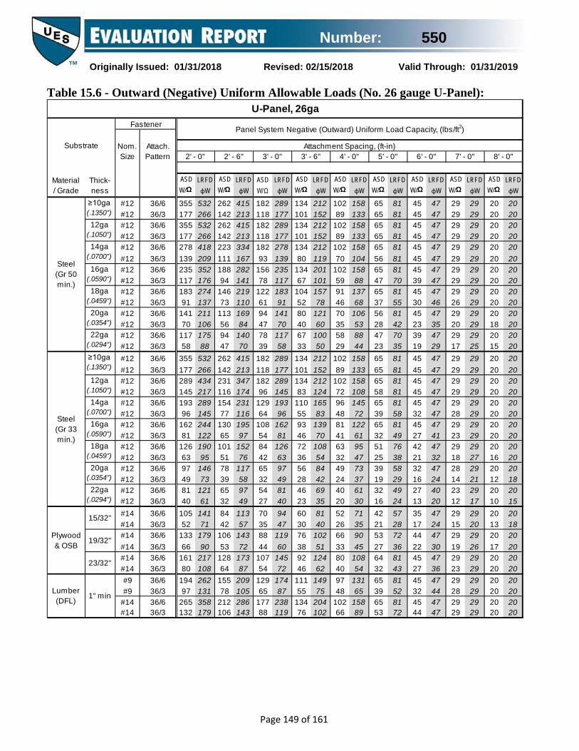
Number: 550
Originally Issued: 01/31/2018 Revised: 02/15/2018 Valid Through: 01/31/2019
Page 149 of 161
Table 15.6 - Outward (Negative) Uniform Allowable Loads (No. 26 gauge U-Panel):
Thick- ness
ASD W/Ω
ASD W/Ω
ASD W/Ω
ASD W/Ω
ASD W/Ω
ASD W/Ω
ASD W/Ω
ASD W/Ω
ASD W/Ω
#12 36/6 355 262 182 134 102 65 45 29 20#12 36/3 177 142 118 101 89 65 45 29 20#12 36/6 355 262 182 134 102 65 45 29 20#12 36/3 177 142 118 101 89 65 45 29 20#12 36/6 278 223 182 134 102 65 45 29 20#12 36/3 139 111 93 80 70 56 45 29 20#12 36/6 235 188 156 134 102 65 45 29 20#12 36/3 117 94 78 67 59 47 39 29 20#12 36/6 183 146 122 104 91 65 45 29 20#12 36/3 91 73 61 52 46 37 30 26 20#12 36/6 141 113 94 80 70 56 45 29 20#12 36/3 70 56 47 40 35 28 23 20 18#12 36/6 117 94 78 67 58 47 39 29 20#12 36/3 58 47 39 33 29 23 19 17 15#12 36/6 355 262 182 134 102 65 45 29 20#12 36/3 177 142 118 101 89 65 45 29 20#12 36/6 289 231 182 134 102 65 45 29 20#12 36/3 145 116 96 83 72 58 45 29 20#12 36/6 193 154 129 110 96 65 45 29 20#12 36/3 96 77 64 55 48 39 32 28 20#12 36/6 162 130 108 93 81 65 45 29 20#12 36/3 81 65 54 46 41 32 27 23 20#12 36/6 126 101 84 72 63 51 42 29 20#12 36/3 63 51 42 36 32 25 21 18 16#12 36/6 97 78 65 56 49 39 32 28 20#12 36/3 49 39 32 28 24 19 16 14 12#12 36/6 81 65 54 46 40 32 27 23 20#12 36/3 40 32 27 23 20 16 13 12 10#14 36/6 105 84 70 60 52 42 35 29 20#14 36/3 52 42 35 30 26 21 17 15 13#14 36/6 133 106 88 76 66 53 44 29 20#14 36/3 66 53 44 38 33 27 22 19 17#14 36/6 161 128 107 92 80 64 45 29 20#14 36/3 80 64 54 46 40 32 27 23 20#9 36/6 194 155 129 111 97 65 45 29 20#9 36/3 97 78 65 55 48 39 32 28 20
#14 36/6 265 212 177 134 102 65 45 29 20#14 36/3 132 106 88 76 66 53 44 29 20
131 8154
2920
108
29
2920
81 47
2020
292927
35
158
20
29 20
2029
47
4758 47 29
202020
81
20
88 7081 47 29
4735
262 209 174
217 173
149
102
108 87 72145 124
62
113
14390 72
29
2914171 57 47
47
26119
45 3647
28
30
40 35179
60 5190
1894 81 71 57
202420
212289177
2020
8181
158133
81
58 2529
47
50
358179
286143
238119
204102
15889
8172
4747
2929
2020
81 47
4743
29 2036 29
20
131 75 65 52
55
88
20119 104 81
29 20
101
47
4681
44
29 2047
44 29 20
72
137274 219 183 157
110 91 78 6847 29
2929
2929152
4747
209201
137176 141 117352 282 235
167 139
U-Panel, 26ga
Substrate
Fastener
Nom. Size
Attach.Pattern
212 158 81 47 29 20
Material/ Grade
Steel(Gr 50 min.)
532 415 289
117 100
121
8853
106
278 212
Panel System Negative (Outward) Uniform Load Capacity, (lbs/ft2)
84169
70141
60
LRFD φW
LRFD φW
LRFD φW
LRFD φW
LRFD φW
LRFD φW
LRFD φW
LRFD φW
LRFD φW
Attachment Spacing, (ft-in)
8142
47
266 133
20
47
22ga (.0294")
2' - 0" 2' - 6" 3' - 0" 3' - 6" 4' - 0"
175106211
140
≥10ga (.1350")
14ga (.0700")
16ga (.0590")
18ga (.0459")
12ga (.1050")
20ga (.0354")
158418 334
532266
415213
70
5' - 0"
70
213 177 152
20217 174 145 124 108 81
289 212 158 81 47
6' - 0" 7' - 0" 8' - 0"
29 2081
29
12ga (.1050")
434 347 289 212 158
16ga (.0590")
244 195 162 139 122
14ga (.0700")
122 97 81 70 61
145 116 96 83 72289 231 193 165 145 81
84 73
6140
49 4147
95 76 63 54 47 38 32
Steel(Gr 33 min.)
20
415
20
22ga (.0294")
121 97 81 69 61 49
58 4773 58 49 42
18ga (.0459")
190 152 126 108 95 76
15/32"
2018
29 20
2020
29 20
49 40 35 30 24 20
24 2129
37 2920ga
(.0354")146 117 97
19/32"
23/32"
1" min
Plywood & OSB
Lumber(DFL)
87105
29 20266 213 177 152 133 81 47 29
17 15
≥10ga (.1350")
532
2047 29

Number: 550
Originally Issued: 01/31/2018 Revised: 02/15/2018 Valid Through: 01/31/2019
Page 150 of 161
Table 15.7 - Outward (Negative) Uniform Allowable Loads (No. 24 gauge U-Panel):
Thick- ness
ASD W/Ω
ASD W/Ω
ASD W/Ω
ASD W/Ω
ASD W/Ω
ASD W/Ω
ASD W/Ω
ASD W/Ω
ASD W/Ω
#12 36/6 377 247 171 126 96 62 43 31 24#12 36/3 189 151 126 108 94 62 43 31 24#12 36/6 377 247 171 126 96 62 43 31 24#12 36/3 189 151 126 108 94 62 43 31 24#12 36/6 278 223 171 126 96 62 43 31 24#12 36/3 139 111 93 80 70 56 43 31 24#12 36/6 235 188 156 126 96 62 43 31 24#12 36/3 117 94 78 67 59 47 39 31 24#12 36/6 183 146 122 104 91 62 43 31 24#12 36/3 91 73 61 52 46 37 30 26 23#12 36/6 141 113 94 80 70 56 43 31 24#12 36/3 70 56 47 40 35 28 23 20 18#12 36/6 117 94 78 67 58 47 39 31 24#12 36/3 58 47 39 33 29 23 19 17 15#12 36/6 372 247 171 126 96 62 43 31 24#12 36/3 186 149 124 106 93 62 43 31 24#12 36/6 289 231 171 126 96 62 43 31 24#12 36/3 145 116 96 83 72 58 43 31 24#12 36/6 193 154 129 110 96 62 43 31 24#12 36/3 96 77 64 55 48 39 32 28 24#12 36/6 162 130 108 93 81 62 43 31 24#12 36/3 81 65 54 46 41 32 27 23 20#12 36/6 126 101 84 72 63 51 42 31 24#12 36/3 63 51 42 36 32 25 21 18 16#12 36/6 97 78 65 56 49 39 32 28 24#12 36/3 49 39 32 28 24 19 16 14 12#12 36/6 81 65 54 46 40 32 27 23 20#12 36/3 40 32 27 23 20 16 13 12 10#14 36/6 105 84 70 60 52 42 35 30 24#14 36/3 52 42 35 30 26 21 17 15 13#14 36/6 133 106 88 76 66 53 43 31 24#14 36/3 66 53 44 38 33 27 22 19 17#14 36/6 161 128 107 92 80 62 43 31 24#14 36/3 80 64 54 46 40 32 27 23 20#9 36/6 194 155 129 111 96 62 43 31 24#9 36/3 97 78 65 55 48 39 32 28 24
#14 36/6 265 212 171 126 96 62 43 31 24#14 36/3 132 106 88 76 66 53 43 31 24
131 9854
4227
108
42
4228
98 67
2822
354227
35
153
22
42 28
2842
67
6758 48 41
282628
97
28
88 7098 67 42
5835
262 209 174
217 173
149
102
108 87 72145 124
62
113
14390 72
42
4014171 57 47
47
26119
45 3660
28
30
40 35179
60 5190
1894 81 71 57
202428
200272189
2828
9898
153141
98
58 2529
67
50
358179
286143
238119
200102
15389
9872
6760
4242
2828
87 67
6743
42 2836 31
28
131 75 65 52
55
88
28119 104 84
39 28
101
67
4698
44
42 2859
44 37 28
72
137274 219 183 157
110 91 78 6867 42
3042
4242162
6767
209200
137176 141 117352 282 235
167 139
U-Panel, 24ga
Substrate
Fastener
Nom. Size
Attach.Pattern
200 153 98 67 42 28
Material/ Grade
Steel(Gr 50 min.)
566 391 272
117 100
121
8853
106
272 200
Panel System Negative (Outward) Uniform Load Capacity, (lbs/ft2)
84169
70141
60
LRFD φW
LRFD φW
LRFD φW
LRFD φW
LRFD φW
LRFD φW
LRFD φW
LRFD φW
LRFD φW
Attachment Spacing, (ft-in)
8442
67
283 141
28
67
22ga (.0294")
2' - 0" 2' - 6" 3' - 0" 3' - 6" 4' - 0"
175106211
140
≥10ga (.1350")
14ga (.0700")
16ga (.0590")
18ga (.0459")
12ga (.1050")
20ga (.0354")
153418 334
566283
391226
70
5' - 0"
70
226 189 162
28217 174 145 124 108 87
272 200 153 98 67
6' - 0" 7' - 0" 8' - 0"
42 2898
42
12ga (.1050")
434 347 272 200 153
16ga (.0590")
244 195 162 139 122
14ga (.0700")
122 97 81 70 61
145 116 96 83 72289 231 193 165 145 98
84 73
6140
49 4163
95 76 63 54 47 38 32
Steel(Gr 33 min.)
28
391
24
22ga (.0294")
121 97 81 69 61 49
58 4973 58 49 42
18ga (.0459")
190 152 126 108 95 76
15/32"
2818
42 28
2828
42 28
49 40 35 30 24 20
24 2135
37 2920ga
(.0354")146 117 97
19/32"
23/32"
1" min
Plywood & OSB
Lumber(DFL)
87105
42 28279 223 186 159 139 98 67 42
17 15
≥10ga (.1350")
558
2867 42

Number: 550
Originally Issued: 01/31/2018 Revised: 02/15/2018 Valid Through: 01/31/2019
Page 151 of 161
Table 15.8 - Outward (Negative) Uniform Allowable Loads (No. 22 gauge U-Panel):
Thick- ness
ASD W/Ω
ASD W/Ω
ASD W/Ω
ASD W/Ω
ASD W/Ω
ASD W/Ω
ASD W/Ω
ASD W/Ω
ASD W/Ω
#12 36/6 478 323 224 165 126 81 56 41 32#12 36/3 239 191 159 137 119 81 56 41 32#12 36/6 418 323 224 165 126 81 56 41 32#12 36/3 209 167 139 119 104 81 56 41 32#12 36/6 278 223 186 159 126 81 56 41 32#12 36/3 139 111 93 80 70 56 46 40 32#12 36/6 235 188 156 134 117 81 56 41 32#12 36/3 117 94 78 67 59 47 39 34 29#12 36/6 183 146 122 104 91 73 56 41 32#12 36/3 91 73 61 52 46 37 30 26 23#12 36/6 141 113 94 80 70 56 47 40 32#12 36/3 70 56 47 40 35 28 23 20 18#12 36/6 117 94 78 67 58 47 39 33 29#12 36/3 58 47 39 33 29 23 19 17 15#12 36/6 372 297 224 165 126 81 56 41 32#12 36/3 186 149 124 106 93 74 56 41 32#12 36/6 289 231 193 165 126 81 56 41 32#12 36/3 145 116 96 83 72 58 48 41 32#12 36/6 193 154 129 110 96 77 56 41 32#12 36/3 96 77 64 55 48 39 32 28 24#12 36/6 162 130 108 93 81 65 54 41 32#12 36/3 81 65 54 46 41 32 27 23 20#12 36/6 126 101 84 72 63 51 42 36 32#12 36/3 63 51 42 36 32 25 21 18 16#12 36/6 97 78 65 56 49 39 32 28 24#12 36/3 49 39 32 28 24 19 16 14 12#12 36/6 81 65 54 46 40 32 27 23 20#12 36/3 40 32 27 23 20 16 13 12 10#14 36/6 105 84 70 60 52 42 35 30 26#14 36/3 52 42 35 30 26 21 17 15 13#14 36/6 133 106 88 76 66 53 44 38 32#14 36/3 66 53 44 38 33 27 22 19 17#14 36/6 161 128 107 92 80 64 54 41 32#14 36/3 80 64 54 46 40 32 27 23 20#9 36/6 194 155 129 111 97 78 56 41 32#9 36/3 97 78 65 55 48 39 32 28 24
#14 36/6 265 212 177 151 126 81 56 41 32#14 36/3 132 106 88 76 66 53 44 38 32
131 10554
5927
108
59
5940
128 89
4022
355427
35
176
22
59 40
4059
81
8958 48 41
402640
97
40
88 70128 89 59
5835
262 209 174
217 173
149
102
108 87 72145 124
62
113
14390 72
51
4014171 57 47
47
26119
45 3660
28
30
40 35179
60 5190
1894 81 71 57
202435
262356209
4040
128125
200157
128
58 2529
89
50
358179
286143
238119
204102
17989
12872
8960
5951
4040
87 72
8743
59 4036 31
40
131 75 65 52
55
88
40119 104 84
39 34
101
70
46110
44
50 4059
44 37 33
72
137274 219 183 157
110 91 78 6870 59
3050
5959179
8989
209201
137176 141 117352 282 235
167 139
U-Panel, 22ga
Substrate
Fastener
Nom. Size
Attach.Pattern
262 200 128 89 59 40
Material/ Grade
Steel(Gr 50 min.)
717 513 356
117 100
121
8853
106
278 239
Panel System Negative (Outward) Uniform Load Capacity, (lbs/ft2)
84169
70141
60
LRFD φW
LRFD φW
LRFD φW
LRFD φW
LRFD φW
LRFD φW
LRFD φW
LRFD φW
LRFD φW
Attachment Spacing, (ft-in)
8442
89
358 179
40
89
22ga (.0294")
2' - 0" 2' - 6" 3' - 0" 3' - 6" 4' - 0"
175106211
140
≥10ga (.1350")
14ga (.0700")
16ga (.0590")
18ga (.0459")
12ga (.1050")
20ga (.0354")
200418 334
627313
501251
70
5' - 0"
70
287 239 205
40217 174 145 124 108 87
356 262 200 128 89
6' - 0" 7' - 0" 8' - 0"
59 40128
59
12ga (.1050")
434 347 289 248 200
16ga (.0590")
244 195 162 139 122
14ga (.0700")
122 97 81 70 61
145 116 96 83 72289 231 193 165 145 116
84 73
6140
49 4163
95 76 63 54 47 38 32
Steel(Gr 33 min.)
36
446
24
22ga (.0294")
121 97 81 69 61 49
58 4973 58 49 42
18ga (.0459")
190 152 126 108 95 76
15/32"
3018
42 37
4030
59 40
49 40 35 30 24 20
24 2135
37 2920ga
(.0354")146 117 97
19/32"
23/32"
1" min
Plywood & OSB
Lumber(DFL)
87105
59 40279 223 186 159 139 112 89 59
17 15
≥10ga (.1350")
558
4072 59

Number: 550
Originally Issued: 01/31/2018 Revised: 02/15/2018 Valid Through: 01/31/2019
Page 152 of 161
Table 15.9 - Shear and Flexibility (No. 29 gauge U-Panel, 36/3):
Table 15.10 - Shear and Flexibility (No. 29 gauge U-Panel, 36/6):
29ga U-Panel 36/3 Attachment Pattern Support Screw: #12 HWH Side Lap Screw: #12 SD
ASD Sn/Ω
LRFD φSn
ASD Sn/Ω
LRFD φSn
ASD Sn/Ω
LRFD φSn
ASD Sn/Ω
LRFD φSn
ASD Sn/Ω
LRFD φSn
ASD Sn/Ω
LRFD φSn
ASD Sn/Ω
LRFD φSn
ASD Sn/Ω
LRFD φSn
ASD Sn/Ω
LRFD φSn
q 249 404 250 406 248 403 249 404 248 403 248 402 238 381 175 280 134 214F q 228 370 229 372 229 373 230 374 223 362 225 366 221 359 175 280 134 214F q 207 337 214 348 201 326 208 337 197 320 195 316 193 313 175 280 134 214F q 165 269 189 307 172 279 157 255 143 233 153 249 135 219 144 234 131 212F q 165 269 143 232 125 203 157 255 143 233 122 198 105 171 120 195 108 175F q 165 269 143 232 125 203 111 180 99 161 122 198 105 171 92 149 81 132F
1 q 165 269 143 232 125 203 111 180 99 161 81 131 66 108 56 91 49 79per span F
q 79 129 62 102 51 83 43 70 37 60 29 47 23 38 19 31 16 26F
Attachment Spacing, (ft-in)Diaphragm Shear Capacities, q (plf) and Flexibility Factors, F (10-6 in/lbs)
102.5
2' - 0" 2' - 6" 3' - 0" 3' - 6" 4' - 0" 5' - 0" 6' - 0" 7' - 0" 8' - 0"
56.8
60.0
65.2
75.2
46.4
48.8
51.1
100.0
51.6
100.4
68.1
72.0
72.0
79.5
58.5
60.9
63.0
53.8
56.2
60.4
63.2
67.7
76.5
109.7
68.3
70.3
72.5
75.8
79.1
79.1
85.3
102.4
91.0
91.0
96.0
96.0
82.8
85.0
86.8
126.7
93.2
94.9
96.5
100.1
100.1
104.5
104.5
116.4
112.7
116.5
116.5
116.5
107.2
108.8
110.8
161.3
168.1
126.5
128.3
129.3
130.9
134.0
134.0
134.0
142.5
158.8
161.3
161.3
161.3
155.8
157.5
none
4"
8"
12"
24"
36"
48"
Side Seam Spacing
29ga U-Panel 36/6 Attachment Pattern Support Screw: #12 HWH Side Lap Screw: #12 SD
ASD Sn/Ω
LRFD φSn
ASD Sn/Ω
LRFD φSn
ASD Sn/Ω
LRFD φSn
ASD Sn/Ω
LRFD φSn
ASD Sn/Ω
LRFD φSn
ASD Sn/Ω
LRFD φSn
ASD Sn/Ω
LRFD φSn
ASD Sn/Ω
LRFD φSn
ASD Sn/Ω
LRFD φSn
q 456 741 458 744 449 730 452 734 445 724 343 548 238 381 175 280 134 214F q 380 618 378 614 376 611 375 609 350 569 343 548 238 381 175 280 134 214F q 331 537 339 550 303 492 314 510 287 466 277 450 238 381 175 280 134 214F q 259 420 286 465 250 407 221 360 198 322 205 333 175 285 175 280 134 214F q 259 420 217 352 186 302 221 360 198 322 163 264 138 224 152 248 134 214F q 259 420 217 352 186 302 162 263 143 233 163 264 138 224 117 191 102 166F
1 q 259 420 217 352 186 302 162 263 143 233 114 186 95 154 80 131 70 113per span F
q 160 260 130 211 107 175 91 148 79 129 62 102 51 83 43 70 37 60F
Attachment Spacing, (ft-in)Diaphragm Shear Capacities, q (plf) and Flexibility Factors, F (10-6 in/lbs)
38.4
2' - 0" 2' - 6" 3' - 0" 3' - 6" 4' - 0" 5' - 0" 6' - 0" 7' - 0" 8' - 0"
19.8
21.8
24.7
29.5
11.6
13.7
15.6
31.7
11.8
35.0
19.2
21.4
21.4
25.0
12.1
14.1
15.8
13.7
15.6
18.7
20.5
23.1
27.2
25.6
12.6
14.3
15.9
18.1
20.0
20.0
23.0
28.5
18.8
18.8
21.2
21.2
13.3
15.0
16.3
23.2
13.7
15.0
16.2
18.4
18.4
20.4
20.4
24.3
18.1
19.9
19.9
19.9
14.4
15.7
17.0
19.9
22.1
15.3
16.6
17.2
18.1
19.6
19.6
19.6
22.4
18.7
19.9
19.9
19.9
16.8
17.9
none
4"
8"
12"
24"
36"
48"
Side Seam Spacing

Number: 550
Originally Issued: 01/31/2018 Revised: 02/15/2018 Valid Through: 01/31/2019
Page 153 of 161
Table 15.11 - Shear and Flexibility (No. 26 gauge U-Panel, 36/3):
Table 15.12 - Shear and Flexibility (No. 26 gauge U-Panel, 36/6):
26ga U-Panel 36/3 Attachment Pattern Support Screw: #12 HWH Side Lap Screw: #12 SD
ASD Sn/Ω
LRFD φSn
ASD Sn/Ω
LRFD φSn
ASD Sn/Ω
LRFD φSn
ASD Sn/Ω
LRFD φSn
ASD Sn/Ω
LRFD φSn
ASD Sn/Ω
LRFD φSn
ASD Sn/Ω
LRFD φSn
ASD Sn/Ω
LRFD φSn
ASD Sn/Ω
LRFD φSn
q 310 503 311 505 309 502 310 503 308 501 308 501 308 500 242 387 185 296F q 284 461 285 463 286 464 286 465 277 450 280 455 275 446 242 387 185 296F q 258 419 267 434 250 406 258 420 245 398 242 394 240 390 239 387 185 296F q 206 334 235 382 214 348 195 317 179 290 191 310 168 273 179 291 162 264F q 206 334 178 289 156 253 195 317 179 290 151 246 131 212 149 243 134 218F q 206 334 178 289 156 253 138 224 123 200 151 246 131 212 114 186 102 165F
1 q 206 334 178 289 156 253 138 224 123 200 101 164 83 135 71 115 61 99per span F
q 99 161 78 127 64 105 54 88 47 76 36 59 29 48 24 40 21 34F
Attachment Spacing, (ft-in)Diaphragm Shear Capacities, q (plf) and Flexibility Factors, F (10-6 in/lbs)
79.6
2' - 0" 2' - 6" 3' - 0" 3' - 6" 4' - 0" 5' - 0" 6' - 0" 7' - 0" 8' - 0"
38.7
41.5
46.1
55.1
29.3
31.5
33.5
73.5
32.3
76.0
44.9
48.4
48.4
55.1
36.3
38.4
40.3
34.3
36.4
40.2
42.7
46.8
54.6
74.4
41.9
43.7
45.7
48.7
51.6
51.6
57.2
72.5
57.7
57.7
62.2
62.2
50.3
52.3
53.9
81.9
56.3
57.8
59.2
62.5
62.5
66.4
66.4
77.1
69.4
72.7
72.7
72.7
64.4
65.9
67.6
97.4
103.6
75.5
77.1
78.0
79.5
82.3
82.3
82.3
89.9
95.2
97.4
97.4
97.4
92.5
94.0
none
4"
8"
12"
24"
36"
48"
Side Seam Spacing
26ga U-Panel 36/6 Attachment Pattern Support Screw: #12 HWH Side Lap Screw: #12 SD
ASD Sn/Ω
LRFD φSn
ASD Sn/Ω
LRFD φSn
ASD Sn/Ω
LRFD φSn
ASD Sn/Ω
LRFD φSn
ASD Sn/Ω
LRFD φSn
ASD Sn/Ω
LRFD φSn
ASD Sn/Ω
LRFD φSn
ASD Sn/Ω
LRFD φSn
ASD Sn/Ω
LRFD φSn
q 567 922 570 926 559 908 562 913 554 901 474 759 329 527 242 387 185 296F q 473 769 470 764 468 761 467 759 436 708 440 716 329 527 242 387 185 296F q 411 668 422 685 377 612 390 634 357 580 345 560 329 527 242 387 185 296F q 322 523 356 579 311 506 276 448 246 400 255 415 218 354 229 372 185 296F q 322 523 270 439 231 376 276 448 246 400 203 329 171 278 190 308 168 273F q 322 523 270 439 231 376 202 328 178 290 203 329 171 278 147 239 128 208F
1 q 322 523 270 439 231 376 202 328 178 290 143 232 118 192 101 164 87 142per span F
q 199 324 162 264 134 218 114 186 99 161 78 127 64 105 54 88 47 76F
Attachment Spacing, (ft-in)Diaphragm Shear Capacities, q (plf) and Flexibility Factors, F (10-6 in/lbs)
33.2
2' - 0" 2' - 6" 3' - 0" 3' - 6" 4' - 0" 5' - 0" 6' - 0" 7' - 0" 8' - 0"
16.4
18.3
20.9
25.2
9.1
11.0
12.7
26.9
9.2
30.0
15.8
17.8
17.8
21.0
9.4
11.2
12.7
11.0
12.7
15.4
17.0
19.3
23.0
21.1
9.7
11.2
12.7
14.6
16.3
16.3
19.0
23.9
15.0
15.0
17.1
17.1
10.0
11.6
12.7
18.5
10.2
11.4
12.4
14.4
14.4
16.3
16.3
19.8
13.9
15.5
15.5
15.5
10.7
11.8
12.9
14.7
16.7
11.1
12.2
12.8
13.6
15.0
15.0
15.0
17.5
13.7
14.7
14.7
14.7
12.0
13.0
none
4"
8"
12"
24"
36"
48"
Side Seam Spacing

Number: 550
Originally Issued: 01/31/2018 Revised: 02/15/2018 Valid Through: 01/31/2019
Page 154 of 161
Table 15.13 - Shear and Flexibility (No. 24 gauge U-Panel, 36/3):
Table 15.14 - Shear and Flexibility (No. 24 gauge U-Panel, 36/6):
24ga U-Panel 36/3 Attachment Pattern Support Screw: #12 HWH Side Lap Screw: #12 SD
ASD Sn/Ω
LRFD φSn
ASD Sn/Ω
LRFD φSn
ASD Sn/Ω
LRFD φSn
ASD Sn/Ω
LRFD φSn
ASD Sn/Ω
LRFD φSn
ASD Sn/Ω
LRFD φSn
ASD Sn/Ω
LRFD φSn
ASD Sn/Ω
LRFD φSn
ASD Sn/Ω
LRFD φSn
q 329 535 330 537 328 533 329 535 328 533 327 532 327 532 327 532 278 445F q 301 490 303 492 304 493 304 494 295 479 298 484 292 474 295 479 278 445F q 274 446 284 461 266 432 275 446 261 423 257 418 255 415 254 412 252 410F q 219 355 250 406 228 370 207 337 190 308 203 329 179 290 190 309 173 281F q 219 355 189 308 166 269 207 337 190 308 161 261 139 226 159 258 143 232F q 219 355 189 308 166 269 146 238 131 213 161 261 139 226 122 198 108 176F
1 q 219 355 189 308 166 269 146 238 131 213 108 175 89 145 76 123 66 107per span F
q 106 172 84 137 69 113 59 95 51 82 40 64 32 52 27 44 23 37F
Attachment Spacing, (ft-in)Diaphragm Shear Capacities, q (plf) and Flexibility Factors, F (10-6 in/lbs)
59.9
2' - 0" 2' - 6" 3' - 0" 3' - 6" 4' - 0" 5' - 0" 6' - 0" 7' - 0" 8' - 0"
24.6
27.1
31.1
38.8
16.5
18.4
20.1
51.9
17.9
55.7
27.3
30.3
30.3
36.1
19.9
21.7
23.3
19.6
21.5
24.8
26.9
30.4
37.2
47.3
22.5
24.1
25.8
28.4
30.9
30.9
35.7
49.0
32.9
32.9
36.8
36.8
26.6
28.2
29.7
48.4
29.4
30.7
31.9
34.8
34.8
38.1
38.1
47.4
37.6
40.5
40.5
40.5
33.3
34.6
36.1
51.0
56.3
38.6
40.0
40.7
42.0
44.4
44.4
44.4
51.0
49.1
51.0
51.0
51.0
46.7
48.1
none
4"
8"
12"
24"
36"
48"
Side Seam Spacing
24ga U-Panel 36/6 Attachment Pattern Support Screw: #12 HWH Side Lap Screw: #12 SD
ASD Sn/Ω
LRFD φSn
ASD Sn/Ω
LRFD φSn
ASD Sn/Ω
LRFD φSn
ASD Sn/Ω
LRFD φSn
ASD Sn/Ω
LRFD φSn
ASD Sn/Ω
LRFD φSn
ASD Sn/Ω
LRFD φSn
ASD Sn/Ω
LRFD φSn
ASD Sn/Ω
LRFD φSn
q 603 980 606 984 594 965 598 971 589 957 586 952 494 791 363 581 278 445F q 503 818 500 812 498 809 496 806 463 753 468 761 448 728 363 581 278 445F q 437 711 448 728 400 651 415 674 380 617 366 595 357 581 351 570 278 445F q 342 556 378 615 331 538 293 476 262 426 271 441 232 377 243 395 216 351F q 342 556 287 466 246 399 293 476 262 426 215 350 182 296 202 328 178 290F q 342 556 287 466 246 399 214 348 190 308 215 350 182 296 157 255 137 222F
1 q 342 556 287 466 246 399 214 348 190 308 153 248 127 206 108 175 94 152per span F
q 212 344 173 280 144 233 122 199 106 173 84 137 69 113 59 95 51 82F
Attachment Spacing, (ft-in)Diaphragm Shear Capacities, q (plf) and Flexibility Factors, F (10-6 in/lbs)
27.5
2' - 0" 2' - 6" 3' - 0" 3' - 6" 4' - 0" 5' - 0" 6' - 0" 7' - 0" 8' - 0"
13.1
14.7
17.0
20.7
6.8
8.4
9.9
22.0
6.8
24.8
12.4
14.1
14.1
16.9
6.9
8.4
9.7
8.3
9.8
12.1
13.5
15.5
18.7
16.7
7.0
8.3
9.6
11.3
12.7
12.7
15.0
19.3
11.4
11.4
13.2
13.2
7.1
8.5
9.5
14.2
7.2
8.2
9.1
10.8
10.8
12.4
12.4
15.4
10.2
11.6
11.6
11.6
7.4
8.4
9.4
10.3
12.1
7.5
8.5
9.0
9.8
10.9
10.9
10.9
13.1
9.4
10.3
10.3
10.3
8.0
8.8
none
4"
8"
12"
24"
36"
48"
Side Seam Spacing

Number: 550
Originally Issued: 01/31/2018 Revised: 02/15/2018 Valid Through: 01/31/2019
Page 155 of 161
Table 15.15 - Shear and Flexibility (No. 22 gauge U-Panel, 36/3):
Table 15.16 - Shear and Flexibility (No. 22 gauge U-Panel, 36/6):
22ga U-Panel 36/3 Attachment Pattern Support Screw: #12 HWH Side Lap Screw: #12 SD
ASD Sn/Ω
LRFD φSn
ASD Sn/Ω
LRFD φSn
ASD Sn/Ω
LRFD φSn
ASD Sn/Ω
LRFD φSn
ASD Sn/Ω
LRFD φSn
ASD Sn/Ω
LRFD φSn
ASD Sn/Ω
LRFD φSn
ASD Sn/Ω
LRFD φSn
ASD Sn/Ω
LRFD φSn
q 417 678 419 680 416 676 417 678 415 675 415 674 415 674 415 674 404 647F q 382 621 384 624 385 625 386 626 373 607 377 613 370 601 373 607 368 598F q 348 565 359 584 337 547 348 566 330 537 326 530 323 526 321 522 320 520F q 277 450 317 515 288 469 263 427 241 391 257 417 226 368 241 392 219 356F q 277 450 240 390 210 341 263 427 241 391 204 331 176 286 201 327 181 294F q 277 450 240 390 210 341 186 302 166 270 204 331 176 286 154 251 137 222F
1 q 277 450 240 390 210 341 186 302 166 270 136 222 114 185 97 158 84 137per span F
q 134 218 107 174 88 144 75 122 65 106 51 83 41 67 35 56 30 48F
Attachment Spacing, (ft-in)Diaphragm Shear Capacities, q (plf) and Flexibility Factors, F (10-6 in/lbs)
49.4
2' - 0" 2' - 6" 3' - 0" 3' - 6" 4' - 0" 5' - 0" 6' - 0" 7' - 0" 8' - 0"
18.0
20.2
23.8
30.6
10.8
12.5
14.1
41.2
11.6
45.2
19.3
21.9
21.9
27.1
12.7
14.3
15.7
13.1
14.8
17.7
19.6
22.7
28.7
34.8
14.2
15.5
17.1
19.4
21.6
21.6
25.9
37.6
22.0
22.0
25.4
25.4
16.4
17.9
19.1
33.5
17.9
19.1
20.2
22.7
22.7
25.7
25.7
33.9
23.9
26.5
26.5
26.5
20.1
21.2
22.6
31.3
36.0
22.9
24.2
24.9
26.0
28.1
28.1
28.1
34.0
29.5
31.3
31.3
31.3
27.5
28.7
none
4"
8"
12"
24"
36"
48"
Side Seam Spacing
22ga U-Panel 36/6 Attachment Pattern Support Screw: #12 HWH Side Lap Screw: #12 SD
ASD Sn/Ω
LRFD φSn
ASD Sn/Ω
LRFD φSn
ASD Sn/Ω
LRFD φSn
ASD Sn/Ω
LRFD φSn
ASD Sn/Ω
LRFD φSn
ASD Sn/Ω
LRFD φSn
ASD Sn/Ω
LRFD φSn
ASD Sn/Ω
LRFD φSn
ASD Sn/Ω
LRFD φSn
q 764 1242 767 1247 753 1223 757 1231 747 1213 743 1207 719 1150 528 845 404 647F q 638 1036 634 1030 631 1025 629 1022 587 954 593 964 567 922 528 845 404 647F q 554 901 568 923 507 824 526 854 481 782 464 754 453 736 444 722 404 647F q 434 705 480 779 420 682 371 603 332 539 344 559 294 477 308 501 274 445F q 434 705 364 591 311 506 371 603 332 539 273 443 231 375 256 415 226 367F q 434 705 364 591 311 506 272 441 240 391 273 443 231 375 200 324 174 283F
1 q 434 705 364 591 311 506 272 441 240 391 194 316 161 262 137 223 119 194per span F
q 269 437 219 355 183 297 156 253 136 220 107 174 88 144 75 122 65 106F
Attachment Spacing, (ft-in)Diaphragm Shear Capacities, q (plf) and Flexibility Factors, F (10-6 in/lbs)
23.9
2' - 0" 2' - 6" 3' - 0" 3' - 6" 4' - 0" 5' - 0" 6' - 0" 7' - 0" 8' - 0"
11.0
12.4
14.5
17.7
5.4
6.9
8.2
18.9
5.4
21.4
10.3
11.9
11.9
14.3
5.5
6.8
8.0
6.8
8.1
10.2
11.4
13.2
16.0
14.0
5.5
6.6
7.8
9.3
10.6
10.6
12.6
16.5
9.4
9.4
11.0
11.0
5.6
6.7
7.6
11.7
5.6
6.5
7.3
8.8
8.8
10.2
10.2
12.9
8.2
9.4
9.4
9.4
5.7
6.5
7.4
8.1
9.6
5.7
6.6
7.0
7.7
8.7
8.7
8.7
10.6
7.2
8.1
8.1
8.1
5.9
6.7
none
4"
8"
12"
24"
36"
48"
Side Seam Spacing

Number: 550
Originally Issued: 01/31/2018 Revised: 02/15/2018 Valid Through: 01/31/2019
Page 156 of 161
16.0 X-Span® / Alta Rib Figure 16.1 - Basic Dimensions and Panel Attachment (X-Span / Alta Rib):
36/4 Pattern:
Table 16.1 - Section Properties (X-Span / Alta Rib):
Area Moment of Inertia
Distance to N.A. from
Bottom
Positive Section
Modulus
Negative Section
Modulusw t Fy Fu Ag Ig yb Sg+ Sg-
psf in ksi ksi in2/ft in4/ft in in3/ft in3/ft29 0.73 0.0139 80 82 0.2135 0.1233 1.08 0.1314 0.114526 0.90 0.0173 80 82 0.2657 0.1533 1.08 0.1633 0.1422
Moment of Inertia
Distance to N.A. from
Bottom
Section Modulus
Moment of Inertia
Distance to N.A. from
Bottom
Section Modulus
Ae/ft Ie+ yb Se+ Ie- yb Se- I+ I-
in2 in4/ft in in3/ft in4/ft in in3/ft in4/ft in4/ft29 0.1091 0.1183 1.08 0.1145 0.1117 1.22 0.0852 0.1200 0.115626 0.1490 0.1493 1.08 0.1422 0.1433 1.19 0.1151 0.1507 0.1467
Gauge Weight Base Metal Thickness
Yield Strength
Tensile Strength
Gross Section Properties
Gauge
Effective Section Properties Uniform Load Only
Area
Positive Negative
Id = (2Ie+Ig)/3

Number: 550
Originally Issued: 01/31/2018 Revised: 02/15/2018 Valid Through: 01/31/2019
Page 157 of 161
Table 16.2 - Inward (Positive) Uniform Allowable Loads (X-Span / Alta Rib): Gauge Span Limit
Condition Panel Span (Support Spacing)
2' - 0" 3' - 0" 4' - 0" 5' - 0" 6' - 0" 7' - 0" 8' - 0" 10' - 0" 12' - 0"
29
Single Span
ASD, W/Ω LRFD, φW
685 1087
305 483
171 272
110 174
76 121
56 89
43 68
27 43
19 30
L/240 L/180 L/120
- - -
291 - -
123 164
-
63 84 -
36 49 73
23 31 46
15 20 31
8 10 16
5 6 9
Double Span
ASD, W/Ω LRFD, φW
274 415
156 236
100 151
68 103
49 75
38 57
29 44
19 29
13 20
L/240 L/180 L/180
- - -
- - -
- - -
- - -
- - -
- - -
- - -
- - -
11 - -
Triple Span
ASD, W/Ω LRFD, φW
299 454
176 267
116 175
81 122
60 90
45 69
36 54
24 36
17 25
L/240 L/180 L/120
- - -
- - -
- - -
- - -
- - -
43 - -
29 - -
15 20 -
9 11 -
26
Single Span
ASD, W/Ω LRFD, φW
852 1351
379 601
213 338
136 216
95 150
70 110
53 84
34 54
24 38
L/240 L/180 L/120
- - -
366 - -
154 206
-
79 105
-
46 61 91
29 38 58
19 26 39
10 13 20
6 8 11
Double Span
ASD, W/Ω LRFD, φW
396 600
222 336
140 212
95 144
68 103
52 78
40 61
26 40
18 28
L/240 L/180 L/120
- - -
- - -
- - -
- - -
- - -
- - -
- - -
24 - -
14 - -
Triple Span
ASD, W/Ω LRFD, φW
435 659
253 382
164 247
114 172
83 125
62 94
49 74
32 49
23 34
L/240 L/180 L/120
- - -
- - -
- - -
- - -
- - -
54 - -
36 49 -
19 25 -
11 14 22
Table 16.3 - Allowable Reactions at Supports (X-Span / Alta Rib):
Reactions at Supports based on Web Crippling
Gauge
Condition
Bearing Length of Webs ASD (Pn/Ω) (lbs/ft width) LRFD (φPn) (lbs/ft width)
1.5" 3" 1.5" 3"
29 End Interior
75 207
n/a n/a
120 332
n/a n/a
26 End
Interior 121 179
172 292
194 286
276 467

Number: 550
Originally Issued: 01/31/2018 Revised: 02/15/2018 Valid Through: 01/31/2019
Page 158 of 161
Table 16.4 - Outward (Negative) Uniform Allowable Loads (No. 29 gauge X-Span / Alta Rib):
Thick- ness
ASD W/Ω
ASD W/Ω
ASD W/Ω
ASD W/Ω
ASD W/Ω
ASD W/Ω
ASD W/Ω
ASD W/Ω
ASD W/Ω
#12 36/4 190 127 95 76 63 54 47 38 30
#12 36/4 190 127 95 76 63 54 47 38 30
#12 36/4 186 124 93 74 62 53 46 37 30
#12 36/4 156 104 78 63 52 45 39 31 26
#12 36/4 122 81 61 49 41 35 30 24 20
#12 36/4 94 63 47 38 31 27 23 19 16
#12 36/4 78 52 39 31 26 22 19 16 13
#12 36/4 190 127 95 76 63 54 47 38 30
#12 36/4 190 127 95 76 63 54 47 38 30
#12 36/4 129 86 64 51 43 37 32 26 21
#12 36/4 108 72 54 43 36 31 27 22 18
#12 36/4 84 56 42 34 28 24 21 17 14
#12 36/4 65 43 32 26 22 19 16 13 11
#12 36/4 54 36 27 22 18 15 13 11 9
#14 36/4 70 47 35 28 23 20 17 14 12
#14 36/4 88 59 44 35 29 25 22 18 15
#14 36/4 107 71 54 43 36 31 27 21 18
#9 36/4 129 86 65 52 43 37 32 26 22
#14 36/4 177 118 88 71 59 50 44 35 2948 33238 159 119 95 79 68
19/32"
23/32"
60
35 29174 116 87 70 58 50 44
29 24145 96 72 58 48 41 36
24 20119 80 60 48 40 34 30
1615/32" 94 63 47 38 31 27 24 19
16 1322ga (.0294")
81 54 40 32 27 23
20ga (.0354")
20
28 24 19 1697 65 49 39 32
25 21
32 27
39 32
57 33
16ga (.0590")
162 108 81 65 54 46
18ga (.0459")
71
48
41
126 84 63 51 42 36 32
12ga (.1050")
285 190 142 114 95
≥10ga (.1350")
81
14ga (.0700")
193 129 96 77 64 55
81 71 57 33285 190 142 114 95
1922ga (.0294")
117 78 58 47 39 33 29 23
2320ga (.0354")
141 94 70 56 47 40 35 28
37 3018ga (.0459")
183 122 91 73 61 52
16ga (.0590")
46
67 59 47 33235 156 117 94 78
3314ga (.0700")
278 186 139 111 93 80 70 56
3312ga (.1050")
285 190 142 114 95 81 71 57
33≥10ga (.1350")
285 190 142 114 95 81 71 57
LRFD φW
LRFD φW
4' - 0" 5' - 0" 6' - 0" 7' - 0" 8' - 0"
LRFD φW
LRFD φW
Steel(Gr 50 min.)
Steel(Gr 33 min.)
Plywood & OSB
Lumber(DFL)
1" min
X-Span / Alta Rib, 29ga
Substrate
FastenerPanel System Negative (Outward) Uniform Load Capacity, (lbs/ft2)
Nom. Size
Attach.Pattern
Attachment Spacing, (ft-in)2' - 0" 3' - 0" 12' - 0"10' - 0"
Material/ Grade
LRFD φW
LRFD φW
LRFD φW
LRFD φW
LRFD φW

Number: 550
Originally Issued: 01/31/2018 Revised: 02/15/2018 Valid Through: 01/31/2019
Page 159 of 161
Table 16.5 - Outward (Negative) Uniform Allowable Loads (No. 26 gauge X-Span / Alta Rib):
Thick- ness
ASD W/Ω
ASD W/Ω
ASD W/Ω
ASD W/Ω
ASD W/Ω
ASD W/Ω
ASD W/Ω
ASD W/Ω
ASD W/Ω
#12 36/4 236 158 118 95 79 68 59 47 39
#12 36/4 236 158 118 95 79 68 59 47 39
#12 36/4 186 124 93 74 62 53 46 37 31
#12 36/4 156 104 78 63 52 45 39 31 26
#12 36/4 122 81 61 49 41 35 30 24 20
#12 36/4 94 63 47 38 31 27 23 19 16
#12 36/4 78 52 39 31 26 22 19 16 13
#12 36/4 236 158 118 95 79 68 59 47 39
#12 36/4 193 129 96 77 64 55 48 39 32
#12 36/4 129 86 64 51 43 37 32 26 21
#12 36/4 108 72 54 43 36 31 27 22 18
#12 36/4 84 56 42 34 28 24 21 17 14
#12 36/4 65 43 32 26 22 19 16 13 11
#12 36/4 54 36 27 22 18 15 13 11 9
#14 36/4 70 47 35 28 23 20 17 14 12
#14 36/4 88 59 44 35 29 25 22 18 15
#14 36/4 107 71 54 43 36 31 27 21 18
#9 36/4 129 86 65 52 43 37 32 26 22
#14 36/4 177 118 88 71 59 50 44 35 2948 40238 159 119 95 79 68
19/32"
23/32"
60
35 29174 116 87 70 58 50 44
29 24145 96 72 58 48 41 36
24 20119 80 60 48 40 34 30
1615/32" 94 63 47 38 31 27 24 19
16 1322ga (.0294")
81 54 40 32 27 23
20ga (.0354")
20
28 24 19 1697 65 49 39 32
25 21
32 27
39 32
58 42
16ga (.0590")
162 108 81 65 54 46
18ga (.0459")
72
48
41
126 84 63 51 42 36 32
12ga (.1050")
289 193 145 116 96
≥10ga (.1350")
83
14ga (.0700")
193 129 96 77 64 55
101 89 71 42355 236 177 142 118
1922ga (.0294")
117 78 58 47 39 33 29 23
2320ga (.0354")
141 94 70 56 47 40 35 28
37 3018ga (.0459")
183 122 91 73 61 52
16ga (.0590")
46
67 59 47 39235 156 117 94 78
4214ga (.0700")
278 186 139 111 93 80 70 56
4212ga (.1050")
355 236 177 142 118 101 89 71
42≥10ga (.1350")
355 236 177 142 118 101 89 71
LRFD φW
LRFD φW
4' - 0" 5' - 0" 6' - 0" 7' - 0" 8' - 0"
LRFD φW
LRFD φW
Steel(Gr 50 min.)
Steel(Gr 33 min.)
Plywood & OSB
Lumber(DFL)
1" min
X-Span / Alta Rib, 26ga
Substrate
FastenerPanel System Negative (Outward) Uniform Load Capacity, (lbs/ft2)
Nom. Size
Attach.Pattern
Attachment Spacing, (ft-in)2' - 0" 3' - 0" 12' - 0"10' - 0"
Material/ Grade
LRFD φW
LRFD φW
LRFD φW
LRFD φW
LRFD φW

Number: 550
Originally Issued: 01/31/2018 Revised: 02/15/2018 Valid Through: 01/31/2019
Page 160 of 161
Table 16.6 - Shear and Flexibility (No. 29 gauge X-Span / Alta Rib, 36/4):
Table 16.7 - Shear and Flexibility (No. 26 gauge X-Span / Alta Rib, 36/4):
29ga X-Span 36/4 Attachment Pattern Support Screw: #12 HWH Side Lap Screw: #12 SD
ASD Sn/Ω
LRFD φSn
ASD Sn/Ω
LRFD φSn
ASD Sn/Ω
LRFD φSn
ASD Sn/Ω
LRFD φSn
ASD Sn/Ω
LRFD φSn
ASD Sn/Ω
LRFD φSn
ASD Sn/Ω
LRFD φSn
ASD Sn/Ω
LRFD φSn
ASD Sn/Ω
LRFD φSn
q 324 526 322 523 321 521 320 520 319 519 319 518 319 518 318 512 222 356F q 288 468 288 468 275 448 278 452 270 439 273 444 268 435 266 432 222 356F q 259 420 245 398 237 385 232 376 228 370 225 366 223 363 220 358 218 355F q 207 337 207 337 169 275 178 289 155 251 163 265 147 239 142 231 139 225F q 207 337 154 251 169 275 142 230 121 196 136 221 121 197 121 197 103 168F q 207 337 154 251 117 190 142 230 121 196 104 168 91 147 98 160 82 133F
1 q 207 337 154 251 117 190 93 151 78 126 66 108 58 94 47 76 39 63per span F
q 116 189 73 119 52 85 41 67 34 56 29 48 26 42 21 33 17 28F
Attachment Spacing, (ft-in)Diaphragm Shear Capacities, q (plf) and Flexibility Factors, F (10-6 in/lbs)
70.5
2' - 0" 3' - 0" 4' - 0" 5' - 0" 6' - 0" 7' - 0" 8' - 0" 10' - 0" 12' - 0"
24.1
28.7
32.5
48.5
13.6
16.1
18.3
52.4
14.3
61.2
24.6
27.1
31.0
37.7
15.3
17.6
19.7
16.7
18.9
24.3
26.5
29.6
42.9
44.2
16.1
18.1
20.3
23.9
26.1
29.5
35.4
48.2
25.3
28.2
28.2
33.3
17.0
19.2
21.1
37.9
18.4
20.3
22.2
24.9
27.3
27.3
31.5
40.7
27.2
27.2
30.5
30.5
20.5
22.4
24.0
34.9
38.6
23.9
25.4
27.0
28.4
30.9
30.9
30.9
36.4
33.2
34.9
34.9
34.9
30.8
32.3
none
4"
8"
12"
24"
36"
48"
Side Seam Spacing
26ga X-Span 36/4 Attachment Pattern Support Screw: #12 HWH Side Lap Screw: #12 SD
ASD Sn/Ω
LRFD φSn
ASD Sn/Ω
LRFD φSn
ASD Sn/Ω
LRFD φSn
ASD Sn/Ω
LRFD φSn
ASD Sn/Ω
LRFD φSn
ASD Sn/Ω
LRFD φSn
ASD Sn/Ω
LRFD φSn
ASD Sn/Ω
LRFD φSn
ASD Sn/Ω
LRFD φSn
q 403 655 400 651 399 648 398 647 397 646 397 645 397 644 396 644 308 493F q 359 583 359 583 343 557 346 563 337 547 340 553 333 542 331 538 308 493F q 322 523 305 495 295 479 288 468 284 461 280 456 278 452 274 446 272 442F q 258 419 258 420 211 343 221 360 192 313 203 330 183 297 177 287 173 281F q 258 419 192 312 211 343 176 287 150 244 170 275 151 245 151 246 128 209F q 258 419 192 312 147 239 176 287 150 244 129 209 113 183 123 199 102 166F
1 q 258 419 192 312 147 239 116 188 96 157 83 134 72 118 58 94 48 78per span F
q 146 238 93 151 66 108 51 83 43 69 36 59 32 52 26 42 21 35F
Attachment Spacing, (ft-in)Diaphragm Shear Capacities, q (plf) and Flexibility Factors, F (10-6 in/lbs)
61.4
2' - 0" 3' - 0" 4' - 0" 5' - 0" 6' - 0" 7' - 0" 8' - 0" 10' - 0" 12' - 0"
19.8
24.0
27.4
41.7
10.4
12.6
14.6
44.6
10.8
52.9
19.7
21.9
25.4
31.5
11.4
13.4
15.3
12.9
14.9
19.7
21.7
24.5
36.4
36.7
11.8
13.6
15.6
18.8
20.7
23.8
29.1
40.6
19.7
22.3
22.3
26.9
12.3
14.3
15.9
29.9
13.1
14.8
16.5
18.9
21.1
21.1
24.9
33.1
20.3
20.3
23.3
23.3
14.3
16.0
17.4
23.8
27.1
16.3
17.5
19.0
20.3
22.6
22.6
22.6
27.5
22.3
23.8
23.8
23.8
20.2
21.5
none
4"
8"
12"
24"
36"
48"
Side Seam Spacing

Number: 550
Originally Issued: 01/31/2018 Revised: 02/15/2018 Valid Through: 01/31/2019
Page 161 of 161
CALIFORNIA SUPPLEMENT ASC PROFILES LLC AEP SPAN AND ASC BUILDING PRODUCTS: SINGLE SKIN STEEL ROOF AND WALL PANELS WITH EXPOSED FASTENERS CSI Section: 07 61 00 Sheet Metal Roofing 07 64 00 Sheet Metal Wall Cladding 1.0 RECOGNITION
ASC Profiles LLC Single Skin Steel Roof and Wall Panels with Exposed Fasteners described in ER-0550 have been evaluated for use as exterior roof and wall covering panels. The structural and fire-resistance properties of the panels have been evaluated for compliance with the following codes:
• 2016 California Building Code® (CBC) • 2013 California Building Code® (CBC)
2.0 ADDITIONAL REQUIREMENTS 2.1 Roof panels may be used in “new buildings located in any Fire Hazard Severity Zone or any Wildland-Urban Interface Fire Area designated by the enforcing agency constructed after the application date stipulated in CBC Section 701A.3.1 shall comply with the provisions” in accordance with Sections 701A.3 and 705A of the CBC and with the 2015 IBC as presented in ER-550. 2.2 Pertaining to structures under the jurisdiction of DSA and OSHPD, designs for the transfer of anchorage forces into the diaphragm shall comply with CBC Section 1613A.5.1 of the 2016 CBC.
3.0 SUBSTANTIATING DATA Data submitted in conformance with IAPMO-UES Evaluation Criteria Single Skin Steel Roof and Wall Panels, EC-011, revised June 2015. Any product testing is from laboratories in compliance with ISO/IEC 17025.
4.0 CONTACT INFORMATION
ASC Profiles LLC 2110 Enterprise Blvd. West Sacramento, CA 95691 (800) 360-2477 www.ascprofiles.com
For additional information about this evaluation report please visit
www.uniform-es.org or email at us [email protected]