numerical coupling of geomechanics and fluid flow...
TRANSCRIPT

IEA Symposium & Workshop – Vienna 17-19 Oct. 2011
©IF
P
Renewable energies | Eco-friendly production | Innovative transport | Eco-efficient processes | Sustainable resources
1
Numerical Coupling of Geomechanics and Fluid Flow during Steam Injection in SAGD
S. Zandi (IFP, ENSMP)G. Renard, J.F. Nauroy, N. Guy, (IFP)
M.Tijani, (ENSMP)
IEA Symposium & Workshop – Vienna 17-19 Oct. 2011
2
©IF
P
OutlineIntroduction
Thermal RecoverySAGD ProcessSAGD Geomechanical Effects
SAGD Modeling & Reservoir SimulationReservoir-Geomechanics Coupling ApproachesApplied Coupling Approaches
Application & ResultsModeled Reservoir DescriptionComparison of Coupled Simulation Results
Conclusions
IEA Symposium & Workshop – Vienna 17-19 Oct. 2011
3
©IF
P
IntroductionThermal RecoverySAGD ProcessSAGD Geomechanical Effects
SAGD Modeling & Reservoir SimulationReservoir-Geomechanics Coupling ApproachesApplied Coupling Approaches
Application & ResultsModeled Reservoir DescriptionComparison of Coupled Simulation Results
Conclusions

IEA Symposium & Workshop – Vienna 17-19 Oct. 2011
4
©IF
P
0,1
1
10
100
1000
10000
100000
1000000
10000000
0 100 200 300 400 500 600
Temperature (°C)
Visc
osity
(cP)
Thermal RecoveryBitumen & Heavy Oil
High viscosityEOR
20Water

IEA Symposium & Workshop – Vienna 17-19 Oct. 2011
5
©IF
P
Steam Assisted Gravity Drainage
overburden
underburden
Steam chamberDraining oil +
condensed water
Steam injection well
Oil production well

IEA Symposium & Workshop – Vienna 17-19 Oct. 2011
6
©IF
P
Shear, dilation and heave associated with SAGD (Collins ,2005)
Geomechanical effectsof steam injection
Stress changesDilationShear
ConsequencesPermeability increaseAffect the steam chamber developmentCap rock integrity ...
SAGD Geomechanical Effects
(Dussault , 2008)
IEA Symposium & Workshop – Vienna 17-19 Oct. 2011
7
©IF
P
7
Problem Statement Necessity of Geomechanics in Reservoir EngineeringQuantification of Strain and Stress State in Reservoir
Reservoir productivityCap-Rock integrityHydro fracturingWell failureInterpretation of 4D seismicSteam chamber monitoring

IEA Symposium & Workshop – Vienna 17-19 Oct. 2011
8
©IF
P
8
Problem Statement Necessity of Geomechanics in Reservoir Engineering
Prevention of the risks (Cap rock integrity)Joslyn Steam Release (2006) – SAGD
Induced over pressure
Source : Total E & P Canada -2007
ERCB Staff Review & Analysis - 2010
IEA Symposium & Workshop – Vienna 17-19 Oct. 2011
9
©IF
P
IntroductionThermal RecoverySAGD ProcessSAGD Geomechanical Effects
SAGD Modeling & Reservoir SimulationReservoir-Geomechanics Coupling ApproachesApplied Coupling Approaches
Application & ResultsModeled Reservoir DescriptionComparison of Coupled Simulation Results
Conclusions
IEA Symposium & Workshop – Vienna 17-19 Oct. 2011
10
©IF
P
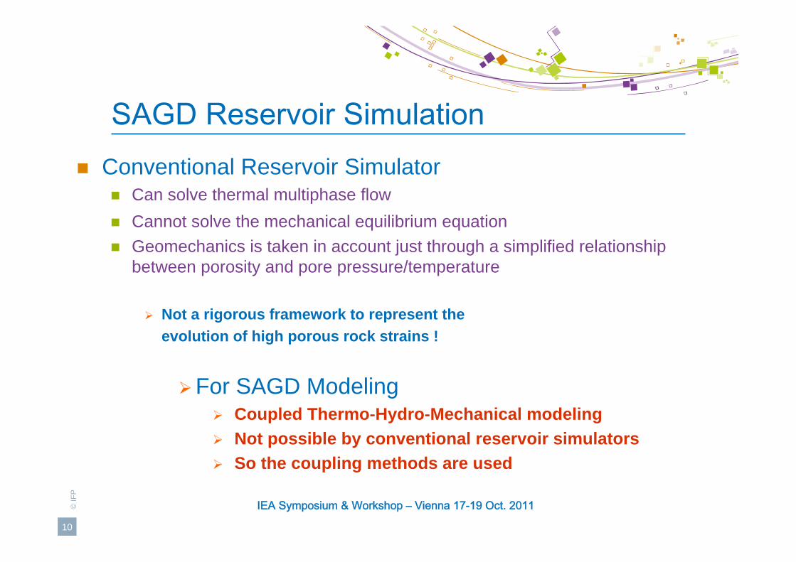
SAGD Reservoir SimulationConventional Reservoir Simulator
Can solve thermal multiphase flowCannot solve the mechanical equilibrium equationGeomechanics is taken in account just through a simplified relationship between porosity and pore pressure/temperature
Not a rigorous framework to represent the evolution of high porous rock strains !
For SAGD Modeling Coupled Thermo-Hydro-Mechanical modelingNot possible by conventional reservoir simulatorsSo the coupling methods are used

IEA Symposium & Workshop – Vienna 17-19 Oct. 2011
11
©IF
P
Thermo-Hydro-Mechanical Coupling
Fully-Coupled Sequentially-Coupled
Explicit Iterative
Solving the Equations simultaneously
Time Consuming
Solving the Equations Separately
One Way
Reservoir–Geomechanics Coupling Approaches

IEA Symposium & Workshop – Vienna 17-19 Oct. 2011
12
©IF
P
12
Reservoir–Geomechanics Coupling Approaches
One-wayReservoir simulator result is transferred to geomechanical simulatorNo feed back of geomechanical simulator into reservoir simulator.
ExplicitExchange between two simulators is performed only once per each coupling period.
IterativeExchange between two simulators is repeated until convergence under a given criterion.
Sequentially-Coupled Approaches
Geomechanics
Geomechanics
Geomechanics
Reservoir
Reservoir
Reservoir

IEA Symposium & Workshop – Vienna 17-19 Oct. 2011
13
©IF
P
13
One-way Coupling Approach
Reservoir Simulator(PUMA FLOW)
Geomechanical Simulator
(ABAQUS)
PUMA2ABAIFP Coupling Module developed in Python + Fortran
Compute P, T

IEA Symposium & Workshop – Vienna 17-19 Oct. 2011
14
©IF
P
14
Reservoir Simulator(PUMA FLOW)
Compute
Geomechanical Simulator
(ABAQUS)
vε
Explicit Coupling Approach
vc
kk ε
φ00ln =
PUMA2ABA
Permeability update by empirical formulation (from Touhidi-Baghini 1998)
Compute εσ ,,u
Compute P, T
Updating of Permeability
IEA Symposium & Workshop – Vienna 17-19 Oct. 2011
15
©IF
P
15
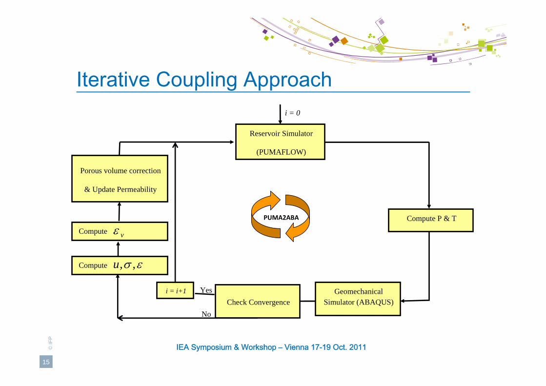
Iterative Coupling Approach
Reservoir Simulator
(PUMAFLOW)
Porous volume correction
& Update Permeability
Compute
Compute
Geomechanical Simulator (ABAQUS)
PUMA2ABA
Yes
i = 0
i = i+1
No
Compute P & T
εσ ,,u
vε
Check Convergence

IEA Symposium & Workshop – Vienna 17-19 Oct. 2011
16
©IF
P
IntroductionThermal RecoverySAGD ProcessSAGD Geomechanical Effects
SAGD Modeling & Reservoir SimulationReservoir-Geomechanics Coupling ApproachesApplied Coupling Approaches
Application & ResultsModeled Reservoir DescriptionComparison of Coupled Simulation Results
Conclusions

IEA Symposium & Workshop – Vienna 17-19 Oct. 2011
17
©IF
P
Modeled Reservoir Description

IEA Symposium & Workshop – Vienna 17-19 Oct. 2011
18
©IF
P
Reservoir – Geomechanics CouplingGeomechanical Simulator
Discretization of geomechanical model:x : 65y : 1 z : 46Linear poro thermo elasticity
Reservoir SimulatorDiscretization of reservoir model:x : 65y : 1 z : 40
Triphasic flow (water, oil, steam)
Reservoir
Geomechanics
XY
Z
Total 3055 grid blocks
Total 2600 grid blocks
730 m
20 m
147 m

IEA Symposium & Workshop – Vienna 17-19 Oct. 2011
19
©IF
P
19
Reservoir – Geomechanics CouplingBoundary Conditions:
Reservoir Simulator:No flow at the boundariesNo heat transfer at the lateral boundariesHeat transfer through the upper and lower boundaries
Geomechanical Simulator: Lower boundary is blockedUpper boundary is freeNo normal displacement on the lateral boundaries

IEA Symposium & Workshop – Vienna 17-19 Oct. 2011
20
©IF
P
20
Comparison of Coupled Simulation
Applied coupling methods
One-way
Explicit coupling
5-step
12-step
Reservoir
Geomechanics
0 150 300 1000 2000 days
Reservoir
Geomechanics
1200 1500400200 600
500 800
Geomechanics
0 150 300 1000 2000 days
Reservoir
0 150 300 1000 2000 days
IEA Symposium & Workshop – Vienna 17-19 Oct. 2011
21
©IF
P
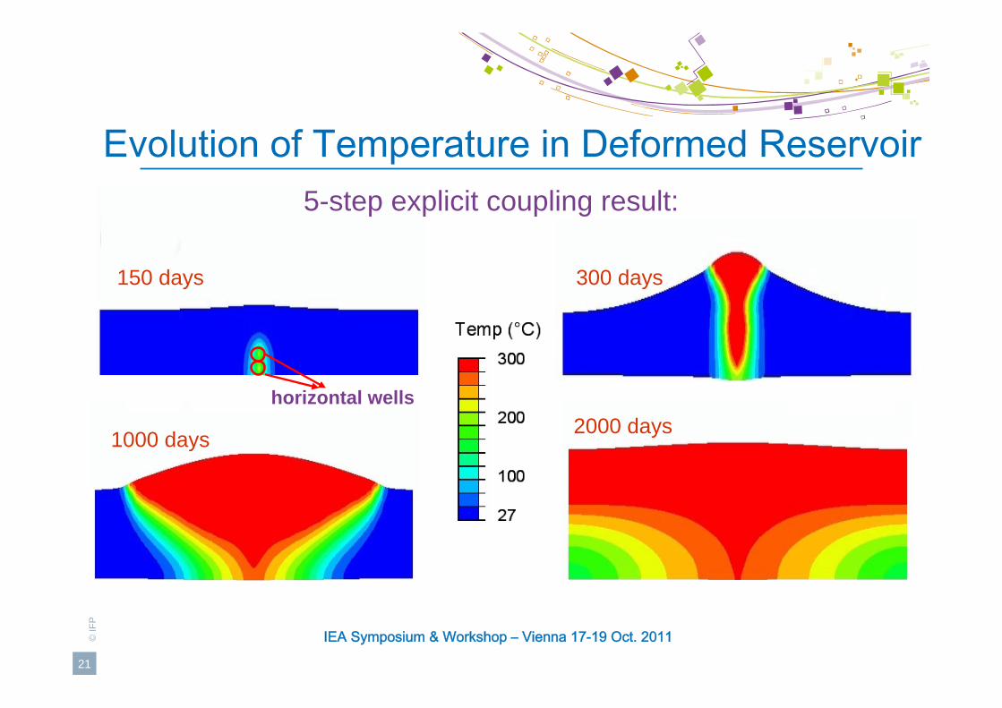
Evolution of Temperature in Deformed Reservoir
150 days 300 days
1000 days 2000 dayshorizontal wells
5-step explicit coupling result:

IEA Symposium & Workshop – Vienna 17-19 Oct. 2011
22
©IF
P
22
Evolution of Volumetric Strain in Reservoir
150 days 300 days
1000 days 2000 days
5-step explicit coupling result:
vc
kk ε
φ00ln =

IEA Symposium & Workshop – Vienna 17-19 Oct. 2011
23
©IF
P
00.5
11.5
22.5
33.5
4
0 5 10 15
ABC
00.5
11.5
22.5
33.5
4
0 5 10 15
ABC
00.5
11.5
22.5
33.5
4
0 5 10 15
ABCq
(MPa
)
p' (MPa)
initialstate
A CB
Stress Path & Impact of the number of coupling periods
12-step coupling
one-way 5-step couplingp' (MPa)
p' (MPa)
IEA Symposium & Workshop – Vienna 17-19 Oct. 2011
24
©IF
P
05
101520253035
0 50 100 150Vert
ical
dis
plac
emen
t (cm
)
Reservoir interface (m)
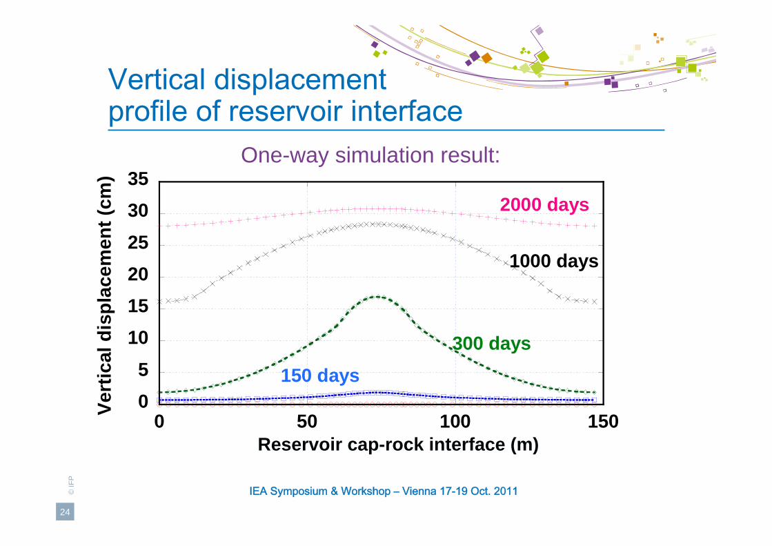
2000 days
1000 days
300 days150 days
Vertical displacement profile of reservoir interface
One-way simulation result:
Reservoir cap-rock interface (m)

IEA Symposium & Workshop – Vienna 17-19 Oct. 2011
25
©IF
P
25
2526272829303132
0 50 100 150
one way5 steps12 steps
Vert
ical
dis
plac
emen
t (cm
)
Reservoir interface (m)
Vertical displacement profile of reservoir cap-rock interface

IEA Symposium & Workshop – Vienna 17-19 Oct. 2011
26
©IF
P
IntroductionThermal RecoverySAGD ProcessSAGD Geomechanical Effects
SAGD Modeling & Reservoir SimulationReservoir-Geomechanics Coupling ApproachesApplied Coupling Approaches
Application & ResultsModeled Reservoir DescriptionComparison of Coupled Simulation Results
Conclusions

IEA Symposium & Workshop – Vienna 17-19 Oct. 2011
27
©IF
P
ConclusionsModeling of SAGD geomechanical effects are necessaryReservoir – geomechanical coupled simulations are requiredSimulation results depend on the chosen coupled approachThe one-way approach, can indicate the most mechanically stressed areasThe explicit coupling approach is more accurate but also more time consuming
Current work :Reduction of CPU time by using a distinct grid methodApply the proposed approach to a heterogeneous mediaImplement the iterative coupling approach

IEA Symposium & Workshop – Vienna 17-19 Oct. 2011
28
©IF
P
Thank You !