numerical missile impact analyses on concrete...
TRANSCRIPT

Joint Research Centre (JRC)IE - Institute for EnergyPetten - The Netherlandshttp://ie.jrc.ec.europa.eu/
Numerical Missile Impact Analyses onConcrete Containment Buildings ofNuclear Power Plants: Review and Recent Progress
Oliver Martin
HTC2010, 27th - 29th October 2010, Versailles 1

HTC2010, 27th - 29th October 2010, Versailles 2
Missile Impact Analysis & Testing on Concrete Containment Buildings of Nuclear Power Plants (NPPs) - Overview
OECD-NEA Benchmark Project IRIS
Modelling Approach & Computational Results
Content

HTC2010, 27th - 29th October 2010, Versailles 3
Missile Impact Analysis & Testing on Concrete Containment Buildings of
Nuclear Power Plants-
Overview

HTC2010, 27th - 29th October 2010, Versailles 4
Early Analyses & Tests
First considerations made in the 1970s when most of today’s operating NPPs were built.
Missile Impact TestsLarge Scale Tests (Meppen Slab Tests, Tests at Sandia, …)Lab Scale Tests (Tests by CEA/EDF, …)
Computational AnalysesEmpirical Formulas (mostly for assessing penetration depth)Finite Difference and Finite Element Approaches
With load curve (Riera Method)Complete numerical models including mesh for missile
Meshes used in early numerical models were course.

HTC2010, 27th - 29th October 2010, Versailles 5
Numerical Analyses involving Load Curves – Riera Method
Principle: Impact of Missile on Containment Structure simulated by Load Curve (resembling Contact Force)
Advantage: No contact modelling required allowing numerically stable analyses (Asset in 1970s because of limited hardware capacities) Disadvantage: Impact Effects on Missile cannot be assessed.
Riera Method is still used extensively today, especially for analyses involving models of complete Containment Buildings !!
HTC2010, 27th - 29th October 2010, Versailles 6
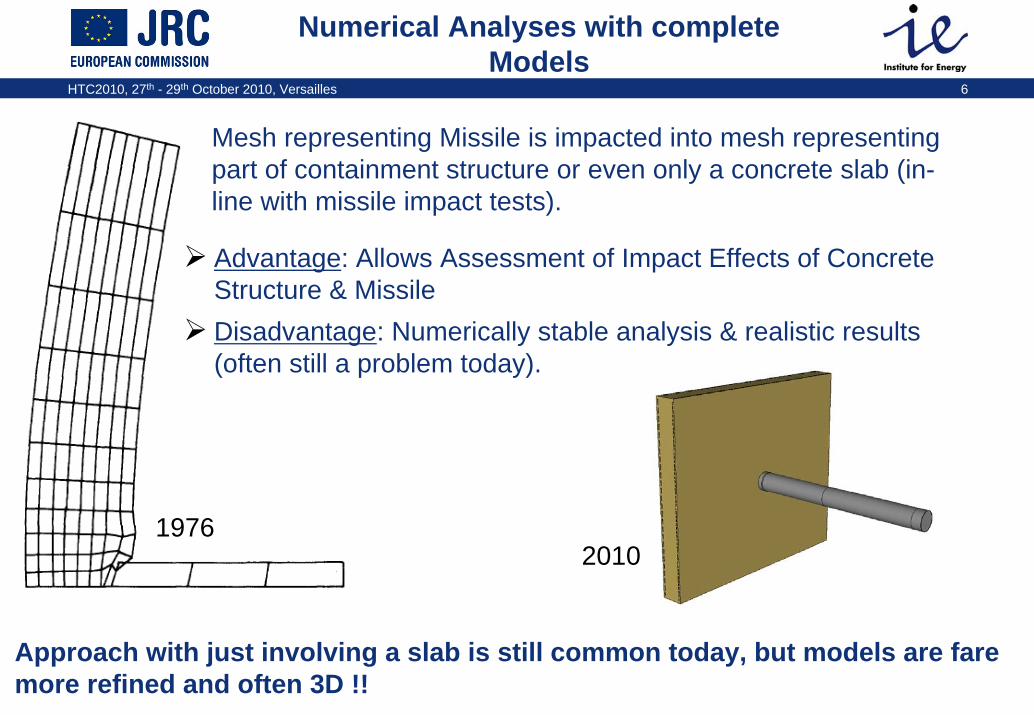
Numerical Analyses with complete Models
Advantage: Allows Assessment of Impact Effects of Concrete Structure & Missile Disadvantage: Numerically stable analysis & realistic results (often still a problem today).
Approach with just involving a slab is still common today, but models are fare more refined and often 3D !!
Mesh representing Missile is impacted into mesh representing part of containment structure or even only a concrete slab (in-line with missile impact tests).
1976 2010
HTC2010, 27th - 29th October 2010, Versailles 7
OECD-NEA Benchmark Project IRIS

HTC2010, 27th - 29th October 2010, Versailles 8
IRIS – Aims, Duration, Procedure
Aim of Benchmark: To assess State-of-the-Art of Modellingof Missile Impacts on Concrete Containment Structures
Request: Large variety in methods (FE, Finite Difference), modelling approaches & solvers (ABAQUS/Explicit, LS-Dyna3D, …) desired !!
“Improving Robustness Assessment Methodologies for Structures impacted by Missiles (IRIS)”
Duration: 1 Year (Jan – Dec 2010)
Wide Participation of nuclear Organisations (25 organisations):Tractebel (B)AECL, CNSC (CA)NRI Rez (CZ) Stuk, VTT (FI)CEA, EDF, IRSN (F)Areva NPP GmbH, GRS (D)
KINS (KOR)JNES (J)NRA (SK)Sandia National Laboratories (USA)JRC, Fusion for Energy (EU)…

HTC2010, 27th - 29th October 2010, Versailles 9
Missile Impact Tests within IRIS
Numerical Analyses are performed on 3 Tests:
VTT-IRSN Flexural Test (new)VTT-CNSC-IRSN Punching Shear Test (new)Meppen-II-4 Test (late 1970s, flexural test)
Test results are distributed to benchmark participants by 3rd November 2010 to assess quality of their numerical analyses.
HTC2010, 27th - 29th October 2010, Versailles 10
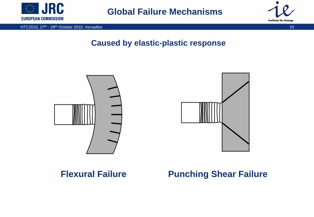
Global Failure Mechanisms
Flexural Failure Punching Shear Failure
Caused by elastic-plastic response
HTC2010, 27th - 29th October 2010, Versailles 11
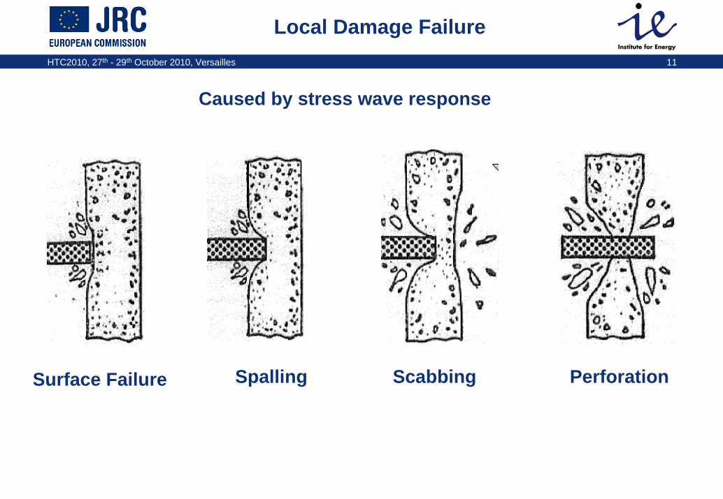
Local Damage Failure
Surface Failure Spalling Scabbing Perforation
Caused by stress wave response

HTC2010, 27th - 29th October 2010, Versailles 12
VTT-IRSN Flexural Test
Missile Characteristics (soft missile): Thin stainless steel pipe & domeThick carbon steel pipe & plate at rearm=50 kg, v=110 m/s
Slab Characteristics: Dimensions: 2.1m × 2.1m × 0.15 mReinforcement front: φ 6mm, 5cm2/mReinforcement back: φ 6mm, 5cm2/mTransverse reinforcement: φ 6mm, 50cm2/m2
Simply supported along 4 edges in supporting frame
2000
55190
Stainless Steel Dome t = 2
Rotation Mitigators
Carbon Steel plate d=256, t=25
Carbon Steel Pipe d=244.5, t=12.5
Stainless Steel Pipe d=256, t=2

HTC2010, 27th - 29th October 2010, Versailles 13
VTT-CNSC-IRSN Punching Shear Test
Slab Characteristics: Dimensions: 2.1m × 2.1m × 0.25 mReinforcement front: φ 10mm, 8.7cm2/mReinforcement back: φ 10mm, 8.7cm2/mNo transverse reinforcementSimply supported along 4 edges in supporting frame
Missile Characteristics (hard missile): steel pipe filled with light-weight concreteStiff & heavy steel dome at front Thick steel plate at rearm=47 kg, v=135 m/s
Aluminium Pipe
Steel Dome
50580
Light-weight Concrete
Steel Plate d=168.3, t=10
Steel Pipe d=168.3, t=10
HTC2010, 27th - 29th October 2010, Versailles 14
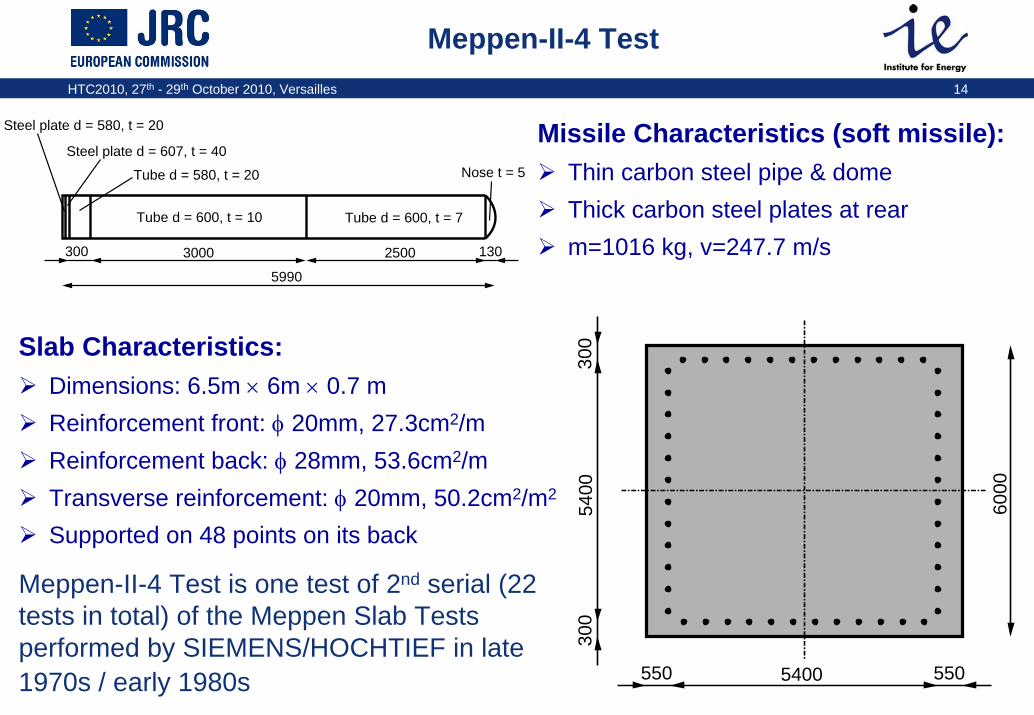
Meppen-II-4 Test
Missile Characteristics (soft missile): Thin carbon steel pipe & domeThick carbon steel plates at rearm=1016 kg, v=247.7 m/s
Slab Characteristics: Dimensions: 6.5m × 6m × 0.7 mReinforcement front: φ 20mm, 27.3cm2/mReinforcement back: φ 28mm, 53.6cm2/mTransverse reinforcement: φ 20mm, 50.2cm2/m2
Supported on 48 points on its back
5400
300
300
6000
5505400550
Steel plate d = 580, t = 20
Steel plate d = 607, t = 40
Tube d = 580, t = 20
Tube d = 600, t = 10 Tube d = 600, t = 7
Nose t = 5
3000 2500 130300
5990
Meppen-II-4 Test is one test of 2nd serial (22 tests in total) of the Meppen Slab Tests performed by SIEMENS/HOCHTIEF in late 1970s / early 1980s
HTC2010, 27th - 29th October 2010, Versailles 15
Modelling Approach & Computational Results
HTC2010, 27th - 29th October 2010, Versailles 16
Overall Strategy of JRC for IRIS
Build-up FE Models on all 3 TestsPerform analyses with RADIOSS & evaluation of results afterwards
Contracted work to Altair Engineering France in order to
JRC then
Transforms RADIOSS models into ABAQUS formatPerforms analyses with ABAQUS/Explicit & evaluation of results afterwards (on-going)
HTC2010, 27th - 29th October 2010, Versailles 17
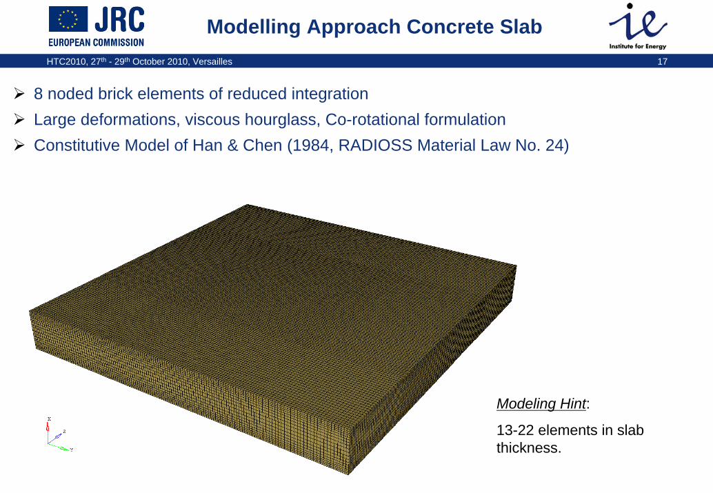
Modelling Approach Concrete Slab
8 noded brick elements of reduced integrationLarge deformations, viscous hourglass, Co-rotational formulationConstitutive Model of Han & Chen (1984, RADIOSS Material Law No. 24)
Modeling Hint:
13-22 elements in slab thickness.

HTC2010, 27th - 29th October 2010, Versailles 18
Constitutive Model of Han & Chen
Type: Drucker-Prager/Cap ModelStandard constitutive model in RADIOSS for pre-stressed concrete (Material Law No. 24)
−σ3
−σ 1
−σ 2 ξ
Failure Surface
Yield Surface
Calibration of material model according to basic material properties distributed to benchmark participants

HTC2010, 27th - 29th October 2010, Versailles 19
Modelling Approach Reinforcement
Linear Beam ElementsProper inertia and cross section definitionNodes of beam elements are merged with nodes of brick elements for the concreteJohnson-Cook Model with strain-rate effects
HTC2010, 27th - 29th October 2010, Versailles 20
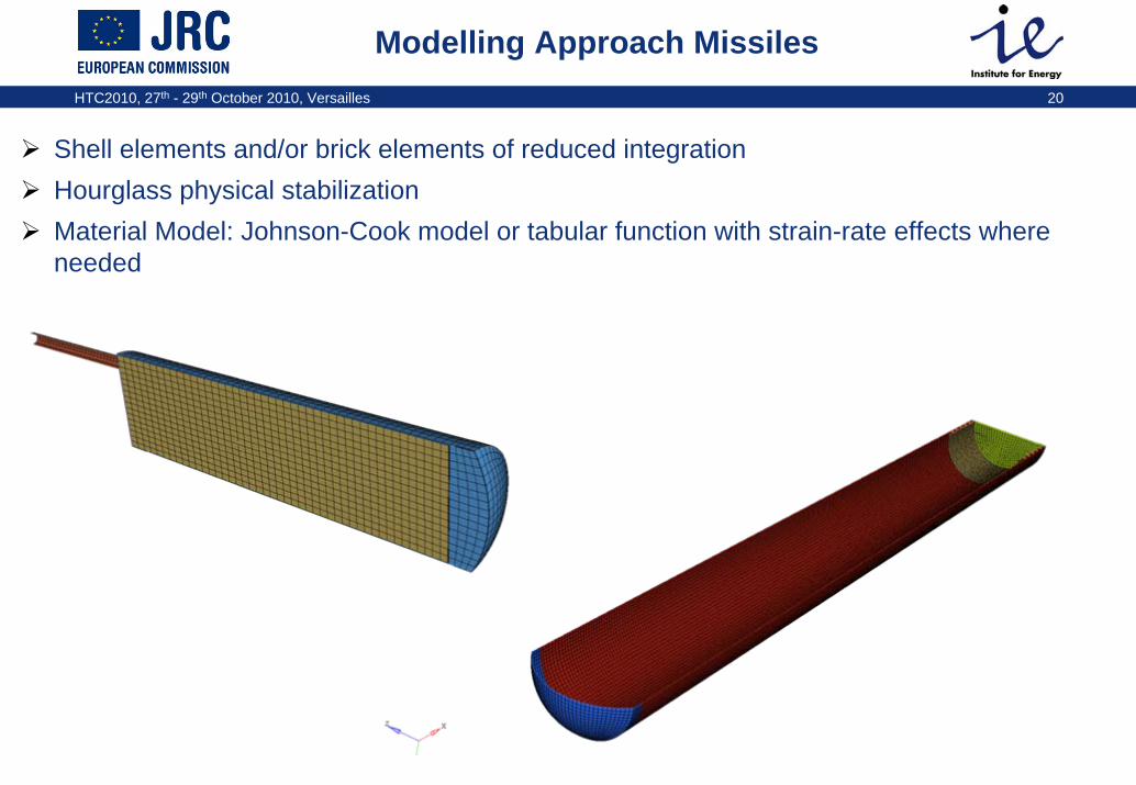
Modelling Approach Missiles
Shell elements and/or brick elements of reduced integrationHourglass physical stabilizationMaterial Model: Johnson-Cook model or tabular function with strain-rate effects where needed

HTC2010, 27th - 29th October 2010, Versailles 21
FE Model VTT-IRSN Flexural Test
Slab Mesh Properties: 351728 brick element, 35384 beam elements, 383418 nodesAverage element size: 15mm; 13 elements in slab thickness
Concrete Material properties: ρ=2280 kg/m3,E=26915 MPa, ν=0.2, Fc = 67.3 MPa, Ft=6.37 MPa, HT=-1400 MPa
Rebar Material Properties: ρ=7.8 t/m3, E=203000 MPa, ν=0.3, Re = 598 MPa, σmax = 670 MPa
Missile Mesh Properties: 29820 elements, 29934 nodesAverage element size: 8mm
Material Properties: ρ=7.8 t/m3, E=205000 MPa, ν=0.3, Re = 220 MPa, σmax = 500 MPa
HTC2010, 27th - 29th October 2010, Versailles 22
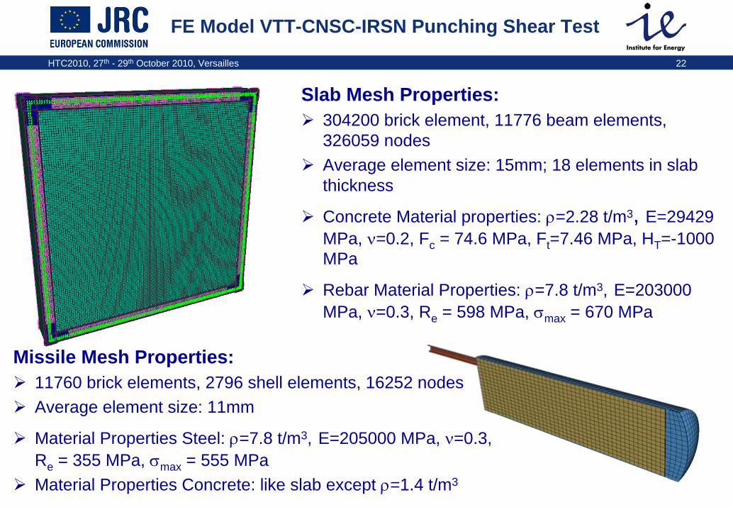
FE Model VTT-CNSC-IRSN Punching Shear Test
Slab Mesh Properties: 304200 brick element, 11776 beam elements, 326059 nodesAverage element size: 15mm; 18 elements in slab thickness
Concrete Material properties: ρ=2.28 t/m3, E=29429 MPa, ν=0.2, Fc = 74.6 MPa, Ft=7.46 MPa, HT=-1000 MPa
Rebar Material Properties: ρ=7.8 t/m3, E=203000 MPa, ν=0.3, Re = 598 MPa, σmax = 670 MPa
Missile Mesh Properties: 11760 brick elements, 2796 shell elements, 16252 nodesAverage element size: 11mm
Material Properties Steel: ρ=7.8 t/m3, E=205000 MPa, ν=0.3, Re = 355 MPa, σmax = 555 MPaMaterial Properties Concrete: like slab except ρ=1.4 t/m3

HTC2010, 27th - 29th October 2010, Versailles 23
Meppen-II-4 Test
Slab Mesh Properties: 727584 brick element, 61440 beam elements, 769143 nodesAverage element size: 35mm; 22 elements in slab thickness
Concrete Material properties: ρ=2.37 t/m3, E=29053 MPa, ν=0.2, Fc = 37.2 MPa, Ft=4.8 MPa, HT=-3000 MPa
Rebar Material Properties: ρ=7.8 t/m3, E=210000 MPa, ν=0.3, Re = 430 MPa, σmax = 624 MPa
Missile Mesh Properties: 30132 elements, 30038 nodesAverage element size: 20mm
Material Properties: ρ=9.1 t/m3, E=210000 MPa, ν=0.3, Re = 286 MPa, σmax = 411 MPa

HTC2010, 27th - 29th October 2010, Versailles 24
All initial kinetic energy of missile is transformed into deformation energy
Contact force between missile and slab scatters in beginning and then stabilizes & decreases to zero
50% of initial length of Missile crumbles away.
Results Analysis VTT-IRSN Flexural Test
Load time history between the missile and the target
-1.00E+02
0.00E+00
1.00E+02
2.00E+02
3.00E+02
4.00E+02
5.00E+02
6.00E+02
0.00 10.00 20.00 30.00 40.00
Time (ms)
Load
forc
e (k
N)

HTC2010, 27th - 29th October 2010, Versailles 25
Shear cone formed and slab bended slightly
Typical crack pattern of flexural test
Slab vibrates due to impact.
Results Analysis VTT-IRSN Flexural Test (cont.)
Displacement time histories at the rear of the slab : w1
-1.20E+01
-1.00E+01
-8.00E+00
-6.00E+00
-4.00E+00
-2.00E+00
0.00E+000.0 10.0 20.0 30.0 40.0 50.0 60.0 70.0 80.0 90.0 100.0
Time (ms)
Dis
plce
men
t w1
(m)

HTC2010, 27th - 29th October 2010, Versailles 26
All initial kinetic energy of missile is transformed into deformation energy rather quickly (hard contact)
Contact force between missile and slab shows no scatter in beginning and decreases quickly to zero
Missile shows only little deformation.
Results Analysis VTT-CNSC-IRSN Punching Shear Test
Load time history between the missile and the target
-1.00E+03
0.00E+00
1.00E+03
2.00E+03
3.00E+03
4.00E+03
5.00E+03
6.00E+03
7.00E+03
8.00E+03
0.00 10.00 20.00
Time (ms)
Load
forc
e (k
N)

HTC2010, 27th - 29th October 2010, Versailles 27
Results Analysis VTT-CNSC-IRSN Punching Shear Test (cont.)
Shear cone formed and large residual deflection of slab
Scabbing
Only little vibrations of slab
Displacement time histories at the rear of the slab : w2
-1.40E-01
-1.20E-01
-1.00E-01
-8.00E-02
-6.00E-02
-4.00E-02
-2.00E-02
0.00E+000.0 10.0 20.0 30.0 40.0 50.0
Time (ms)
Disp
lcem
ent w
2 (m
)
HTC2010, 27th - 29th October 2010, Versailles 28
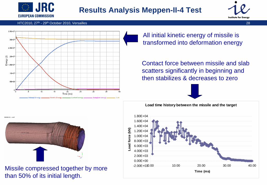
Results Analysis Meppen-II-4 Test
Load time history between the missile and the target
-2.00E+030.00E+002.00E+034.00E+036.00E+038.00E+031.00E+041.20E+041.40E+041.60E+041.80E+04
0.00 10.00 20.00 30.00 40.00
Time (ms)
Load
forc
e (k
N)
All initial kinetic energy of missile is transformed into deformation energy
Contact force between missile and slab scatters significantly in beginning and then stabilizes & decreases to zero
Missile compressed together by more than 50% of its initial length.

HTC2010, 27th - 29th October 2010, Versailles 29
Results Analysis Meppen-II-4 Test (cont.)
Displacement time histories at the rear of the slab : w6
-7.00E-02
-6.00E-02
-5.00E-02
-4.00E-02
-3.00E-02
-2.00E-02
-1.00E-02
0.00E+000.0 10.0 20.0 30.0 40.0 50.0 60.0 70.0 80.0 90.0 100.0
Time (ms)
Disp
lcem
ent w
6 (m
)
Shear cone formed and slab bended slightly
Typical crack pattern of flexural test
Slab vibrates due to impact.
HTC2010, 27th - 29th October 2010, Versailles 30
Summary & next Steps
Results of FE analyses with RADIOSS on the 3 missile impact tests are sound & resonable.Specific results of each analysis show expected results according to slab and missile characteristics. With today’s FE codes it is possible to predict the outcome of missile impact tests realistically.
More in depth results assessment by comparison with measured time responses of deflections, rebar strains, reaction forces, etc…when they are released (next week)!!
HTC2010, 27th - 29th October 2010, Versailles 31
Acknowledgement
Vincent Centro & Thierry Schwoertzig
(Altair Engineering France)
For their efforts to support EC/JRC in the IRIS Benchmark Project.

HTC2010, 27th - 29th October 2010, Versailles 32
Many Thanks for your AttentionMany Thanks for your Attention