numerical modelling of stress state and …
TRANSCRIPT

8$�9������/��(-./+����+������"�#$% ��+� ��
736
NUMERICAL MODELLING OF STRESS STATE AND DEFORMATIONS IN LASER BUTT-
WELDED SHEETS MADE OF X5CRNI18-10 STEEL
PIEKARSKA Wiesława, SATERNUS Zbigniew, KUBIAK Marcin, DOMA�SKI Tomasz
Czestochowa University of Technology, Institute of Mechanics and Machine Design Foundations,
Czestochowa, Poland, EU, [email protected]
Abstract
This work concerns numerical simulations of thermomechanical phenomena in laser butt-welding of sheets
made of X5CrNi18-10 steel. Abaqus FEA software is used in calculations taking into account phase
transformations during material’s state changes and temperature dependent thermomechanical properties of
analysed steel. Additional numerical subroutines are implemented into Abaqus solver in order to describe the
movable heat source power intensity distribution.
The shape and size of melted zone is predicted as well as residual stress and deformations. Real butt-welded
joints are executed in order to verify the results of numerical simulations. Numerically predicted deflection of
the joint is compared to real displacement, measured using profile-graphometer New Form Talysurf 2D/3D
120. Melted zone of the cross section of the joint is compared to numerically predicted geometry of the fusion
zone.
Keywords: Laser welding, Welding deformations, Residual stress, Numerical modelling, Abaqus FEA
1. INTRODUCTION
Highly concentrated heat source used in laser beam welding process causes rapid material melting which
allow achieving the high welding speed and narrow melted zone. A local increase in temperature leads not
only to melting but also to the partial evaporation of steel and to formation of the melting pool as well as keyhole
[1]. The keyhole also stands for the heat source penetrating material. In this welding technique a good quality
welds are obtained with a narrow thermal influence zone, which is helpful in reducing deformations and residual
stress in the work piece and helpful in increasing quality and efficiency of production process [2]. This is
particularly important in welding of long constructions.
Deformations occurring during welding are one of the major problems in the design of welded constructions.
The character and size of deformations depends on the physical properties of the material, rigidity of a
construction and the welding method. The proper selection of the welding technology can reduce deformations
in a large extent. Unquestionable advantages of laser welding contribute to the very intense development of
this technology and wide application in the industry. However, the proper use of this joining method requires a
quantitative analysis and control of occurring deformations and residual stress in welded joints for assumed
various process parameters. At the time the computer simulations by mathematical and numerical modelling
of physical phenomena occurring in the process becomes a helpful tool [3-7].
This work concerns numerical modelling of thermomechanical phenomena in laser welding process, performed
to predict distortion and residual stress in butt-welded sheets made of X5CrNi18-10 steel. Computer
simulations of temperature field as well as stress and strain states are performed in Abaqus FEA supplemented
by additional subroutines where movable heat source power distribution is implemented. Presented results
include temperature distribution, residual stress and the comparison of predicted fusion zone with the
macroscopic picture of the real butt-welded joint cross-section as well as the comparison of estimated
deflections and real displacement, measured using profile-graphometer New Form Talysurf 2D/3D 120.
8$�9������/��(-./+����+������"�#$% ��+� ��
737
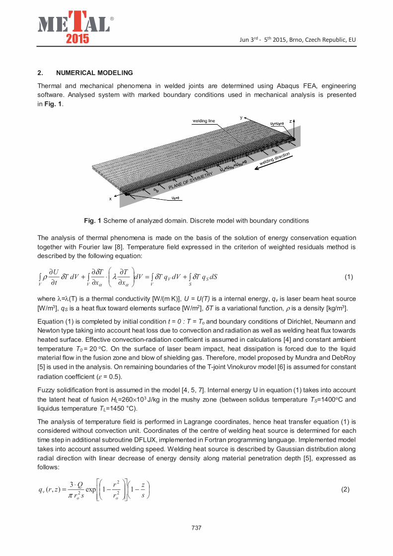
2. NUMERICAL MODELING
Thermal and mechanical phenomena in welded joints are determined using Abaqus FEA, engineering
software. Analysed system with marked boundary conditions used in mechanical analysis is presented
in Fig. 1.
Fig. 1 Scheme of analyzed domain. Discrete model with boundary conditions
The analysis of thermal phenomena is made on the basis of the solution of energy conservation equation
together with Fourier law [8]. Temperature field expressed in the criterion of weighted residuals method is
described by the following equation:
���� +=��
�
�
∂
∂⋅
∂
∂+
∂
∂
SS
VV
VV
dSqTdVqTdVx
T
x
TdVT
t
Uδδλ
δδρ
αα
(1)
where λ=λ(T) is a thermal conductivity [W/(m K)], U = U(T) is a internal energy, qv is laser beam heat source
[W/m3], qS is a heat flux toward elements surface [W/m2], �T is a variational function, ρ is a density [kg/m3].
Equation (1) is completed by initial condition t = 0 : T = To and boundary conditions of Dirichlet, Neumann and
Newton type taking into account heat loss due to convection and radiation as well as welding heat flux towards
heated surface. Effective convection-radiation coefficient is assumed in calculations [4] and constant ambient
temperature T0 = 20 oC. On the surface of laser beam impact, heat dissipation is forced due to the liquid
material flow in the fusion zone and blow of shielding gas. Therefore, model proposed by Mundra and DebRoy
[5] is used in the analysis. On remaining boundaries of the T-joint Vinokurov model [6] is assumed for constant
radiation coefficient (ε = 0.5).
Fuzzy solidification front is assumed in the model [4, 5, 7]. Internal energy U in equation (1) takes into account
the latent heat of fusion HL=260×103 J/kg in the mushy zone (between solidus temperature TS=1400oC and
liquidus temperature TL=1450 °C).
The analysis of temperature field is performed in Lagrange coordinates, hence heat transfer equation (1) is
considered without convection unit. Coordinates of the centre of welding heat source is determined for each
time step in additional subroutine DFLUX, implemented in Fortran programming language. Implemented model
takes into account assumed welding speed. Welding heat source is described by Gaussian distribution along
radial direction with linear decrease of energy density along material penetration depth [5], expressed as
follows:
�
�
�−
���
�
���
�
��
�
�−
⋅=
s
z
r
r
sr
Qzrq
oo
v 11exp3
),(2
2
2π(2)
8$�9������/��(-./+����+������"�#$% ��+� ��
738
where Q is laser beam power [W], r0 is beam radius [m], 22yxr += is actual radius [m], s is penetration
depth [m], z is an actual penetration [m].
Mechanical analysis in elastic-plastic range is based on classic equilibrium equations, supplemented by
constitutive relations as well as initial and boundary conditions (Fig. 1), which are assumed to ensure the
external static determination of considered system [9]:
( ) Ttx ��� ���� ==∇ ,0,α (3)
ee�D�D� ����� += (4)
( ) ( ) ( ) ( ) 0,,,0,, 00 ==== S
ee
S TxtxTxtx αααα ���� (5)
where �=�(�ij) is stress tensor, x� describes location of considered point (material particle), ( ) is inner
exhaustive product, D=D(T) is a tensor of temperature dependent material properties, presented in Table 1.
Elastic strain is modelled for isotropic material using Hooke's law with temperature depended Young's modulus
and Poisson's ratio. Plastic flow model is used to determine plastic strain based on Huber-Mises yield criterion
and isotropic strengthening.
Table 1 Assumed thermomechanical properties of X5CrNi18-10 steel [7]
Thermal properties Mechanical properties
T [oC] " [W/m oC] , [kg/m3] c [J/kg oC] T [oC] E [GPa] Re [MPa] Q [ - ] !T [1/oC]
0 14.6 7900 462 0 198,5 265 0.294 1.7 e-5
100 15.1 7880 496 100 193 218 0.295 1.74 e-5
200 16.1 7830 512 200 185 186 0.301 1.8 e-5
300 17.9 7790 525 300 176 170 0.31 1.86 e-5
400 18 7750 540 400 167 155 0.318 1.91 e-5
600 20.8 7660 577 600 159 149 0.326 1.96 e-5
800 23.9 7560 604 800 151 91 0.333 2.02 e-5
1200 32.2 7370 676 1200 60 25 0.339 2.07 e-5
1300 33.7 7320 692 1300 20 21 0,342 2.11 e-5
1600 120 7320 700 1600 10 10 0.388 2.16 e-5
T - temperature; - conductivity; - density; c - specific heat; E - Young modulus; Re - yield stress; � - Poisson ratio; �T - thermal expansion coefficient
3. RESULTS AND DISCUSSION
Laser butt-welding process is performed at Welding Institute in Gliwice on robotic welding station equipped
with Trumpf TruDisk 12002 laser having maximum power 12 kW. The joint consisting of two plates made of
steel type 304 (X5CrNi18-10) is made without additional material and without a gap.
The displacement of laser butt-welded joints is measured using laboratory New Form Talysurf
profilographometer 2D/3D Taylor Hobson 120. Measurement scheme of the displacement along z-axis in
perpendicular direction to the weld line (the deflection) is shown in Fig. 2.
�

8$�9������/��(-./+����+������"�#$% ��+� ��
739
Fig. 2 Measurements of deformations scheme (L = 150 mm, Lp = 60 mm, b = 90 mm, g = 2 mm
The same process parameters are used in all numerical simulations as in experimental research. Laser beam
power Q = 3 kW, beam radius r0 = 0.3 mm, and welding speed v = 5.2 m/min. Heat source penetration depth
is assumed as s = 0.6 mm on the basis of experimental verification. In order to reduce computational time,
symmetry of the joint is assumed in calculations taking into account appropriate boundary conditions in the
plane of symmetry (Fig. 1).
Obtained temperature distribution in the longitudinal section and cross section of welded joint is presented in
Fig. 3 where solid line points out the boundary of melted zone (isoline TL � 1450oC). Additionally, in this figure
the comparison between numerically estimated characteristic zones in the cross section of the joint and the
real weld is presented.
Fig. 3 Temperature distribution in welded joint with the comparison of predicted melted zone and the real
weld cross-section
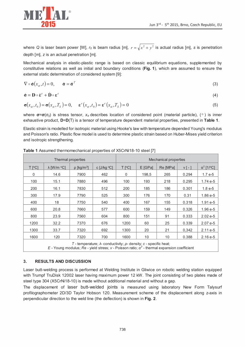
Numerically estimated displacement uz along x-axis in laser welded joint is illustrated in Fig. 4 for three chosen
lines that correspond to experimentally measured deflection along lines presented in Fig. 2. Distributions of
longitudinal reduced residual stresses at the edge and central fibers (lines 1 and 2) and at upper layers (from
the face of the weld) and lower layers (from the ridge of the weld) are shown in Fig. 5.
8$�9������/��(-./+����+������"�#$% ��+� ��
740
Fig. 4 Deflection along x-axis: a) line 1, b) line 2, c) line 3 (corresponding to Fig. 2)
Fig. 5 Residual reduced stress �

8$�9������/��(-./+����+������"�#$% ��+� ��
741
CONCLUSIONS
The comparison of weld geometry and predicted melted zone shape (Fig. 3) and the comparison of estimated
deflection with the real displacement in welded joint (Fig. 4) shows a good agreement of results of numerical
analysis with the experiment which indicates the correctness of developed mathematical and numerical models
of thermal and mechanical phenomena in the laser beam welding process.
Numerical analysis and experimental research confirmed that laser welded joint is deformed in the transverse
and longitudinal directions to the weld line. This is also confirmed by stress distributions. Obtained residual
stress reaches maximum values ~250 MPa in the weld (Fig. 5). Deflection is small and reaches highest value
in welded sheets below 250 �m (Fig. 4).
Presented models of the analysis of thermomechanical phenomena in Abaqus FEA software, allows for the
comprehensive analysis of welding process, including welding deformations in terms of different process
parameters. Therefore developed model may be useful for selecting appropriate parameters that allow
obtaining the proper geometry, quality and mechanical properties the designed joint.
REFERENCES
[1] DAWES, C. Laser Welding, Abington Publishing, New York, 1992.
[2] PILARCZYK, J., BANASIK, M., DWORAK, J., STANO S. Technological applications of laser beam welding and
cutting at the Instytut Spawalnictwa. Przeglad Spawalnictwa, Vol. 5-6, 2006, pp. 6-10.
[3] DENG D., MURAKAWA H. Prediction of welding distortion and residual stress in a thin plate butt-welded joint.
Computational Materials Science, Vol. 43, 2008, pp. 353-365.
[4] DENG D., FEM prediction of welding residual stress and distortion in carbon steel considering phase transformation
effect. Materials and Design, Vol. 30, 2009, pp. 359-366.
[5] BOKOTA A., PIEKARSKA W. Modeling of residual stresses in laser welding. Paton Welding Journal, Vol. 6, 2008,
pp. 19-25.
[6] LACKI P., KUCHARCZYK Z., @LIWA R.E., GAŁACZY�SKI T. Effect of Tool Shape on Temperature Field in Friction
Stir Spot Welding. Archives of Metallurgy and Materials, Vol. 58, 2013, pp. 597-601.
[7] PIEKARSKA, W., KUBIAK, M., SATERNUS Z., REK K. Computer modelling of thermomechanical phenomena in
pipes welded using a laser beam. Archives of Metallurgy and Materials, Vol. 58, 2013, pp. 1237-1242.
[8] DASSAULT SYSTEM, Abaqus theory manual. Version 6.7, SIMULIA, 2007.
[9] BOKOTA, A., DOMA�SKI, T. Numerical analysis of thermo-mechanical phenomena of hardening process of
elements made of carbon steel C80U. Archives of Metallurgy and Materials, Vol. 52, 2007, pp. 277-288.