numerical optimization of reinforced laminated …
TRANSCRIPT
NUMERICAL OPTIMIZATION OF REINFORCED LAMINATED PANELS UNDER COMPRESSION
Leandro B. Campoóa, Flávio L. S. Bussamraa, Francisco K. Arakakib and Alessandro T. Netob
aInstituto Tecnológico de Aeronáutica - ITA, Praça Marechal Eduardo Gomes, 50, São José dos Campos, SP, Brazil, [email protected], [email protected], http://www.ita.br
bEmpresa Brasileira de Aeronáutica - EMBRAER, Av. Brigadeiro Faria Lima, 2170, São José dos Campos, SP, Brazil, [email protected], [email protected],
http://www.embraer.com.br
Keywords: optimization of panels, laminated panels, reinforced panels, stability of structures.
Abstract. This article presents a new methodology for structural optimal pre-sizing of reinforced laminated composite panels under compression, based on a proposal for optimal sizing of integral machined metal panels. Collapse stresses and structural efficiency are taken into account in the analysis of the panel stability. Numerical examples are developed and compared with finite element results to show the applicability of the methodology.
Mecánica Computacional Vol XXIX, págs. 7209-7222 (artículo completo)Eduardo Dvorkin, Marcela Goldschmit, Mario Storti (Eds.)
Buenos Aires, Argentina, 15-18 Noviembre 2010
Copyright © 2010 Asociación Argentina de Mecánica Computacional http://www.amcaonline.org.ar
1 INTRODUCTION
Great part of an aircraft structure is composed by thin plates stiffened by longerons or stiffeners. These structures are susceptible to buckling failure at critical stress or buckling stress, which is usually below the material yield stress. Thus, for this type of structure the buckling is a critical failure mode and, therefore, the prediction of the buckling load for columns, thin plates and stiffened panels is very important in aircraft design. Nowadays, we can see a strong movement in order to expand the use of composite materials in aircraft structures, aiming to increase the structural efficiency, that is, increase the capacity of supporting loads and reducing structure mass. Therefore, composite panels under compression have been extensively studied under various aspects, looking for an increase of the structural efficiency, Lanzi (2004), Bisagni et al (2005), Gavazzi and Arakaki (2007).
Neto (2006) presented an optimization method for integrally machined metal panels under compression.
The objective of this work is to verify if the methodology presented by Neto (2006) is suitable for application on typical aeronautical composite reinforced panels.
So, three different rectangular panels (500mm x 400mm), with two stringers, are numerically analyzed by Finite Element Models:
(a) baseline panel: made of carbon-epoxy, this panel has typical aeronautical dimensions; (b) carbon-epoxy panel: based on Neto (2006) results; (c) aluminum panel: with the same dimensions of (b). Collapse stresses for these panels and its structural efficiencies are presented and
compared.
2 FEM MODELING
It was used the software MSC. Nastran 2007r1. Both skin and stiffeners were modeled with plate CQUAD4 element type. In panels (a) and (b), laminate properties were modeled by PCOMP.
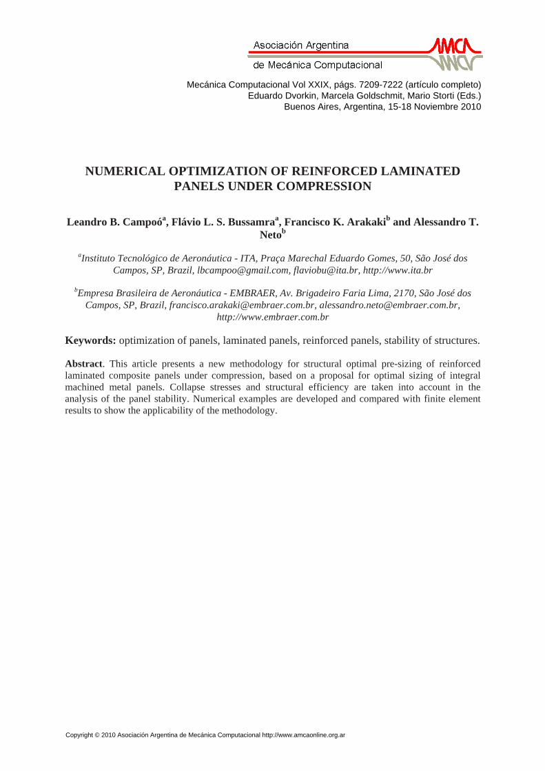
Figure 1 shows the finite element model of the baseline composite panel. The compression loads were applied along one edge of the panel through forced
displacement in the x direction (see Figure 4). In order to translate the forced displacement to loads, it was measured the reaction in the opposite edge to the application of the displacement. The total applied load is obtained by the summation of the nodal loads, and dividing this value by the panel section area it is obtained the applied stress. As boundary conditions, it was restricted the freedom degrees 1 and 3 in the loaded edge, the degrees 1, 2 and 3 in the opposite edge to the application of load and the degrees 2 and 3 in the edges parallel to the loading. Note that degrees 1, 2 and 3 are related to translations in the x, y and z directions, respectively.
Linear buckling was analyzed with solution 105 (SOL105), while nonlinear analyzes were performed with SOL106.
L. CAMPOO, F. BUSSAMRA, F. ARAKAKI, A. NETO7210
Copyright © 2010 Asociación Argentina de Mecánica Computacional http://www.amcaonline.org.ar
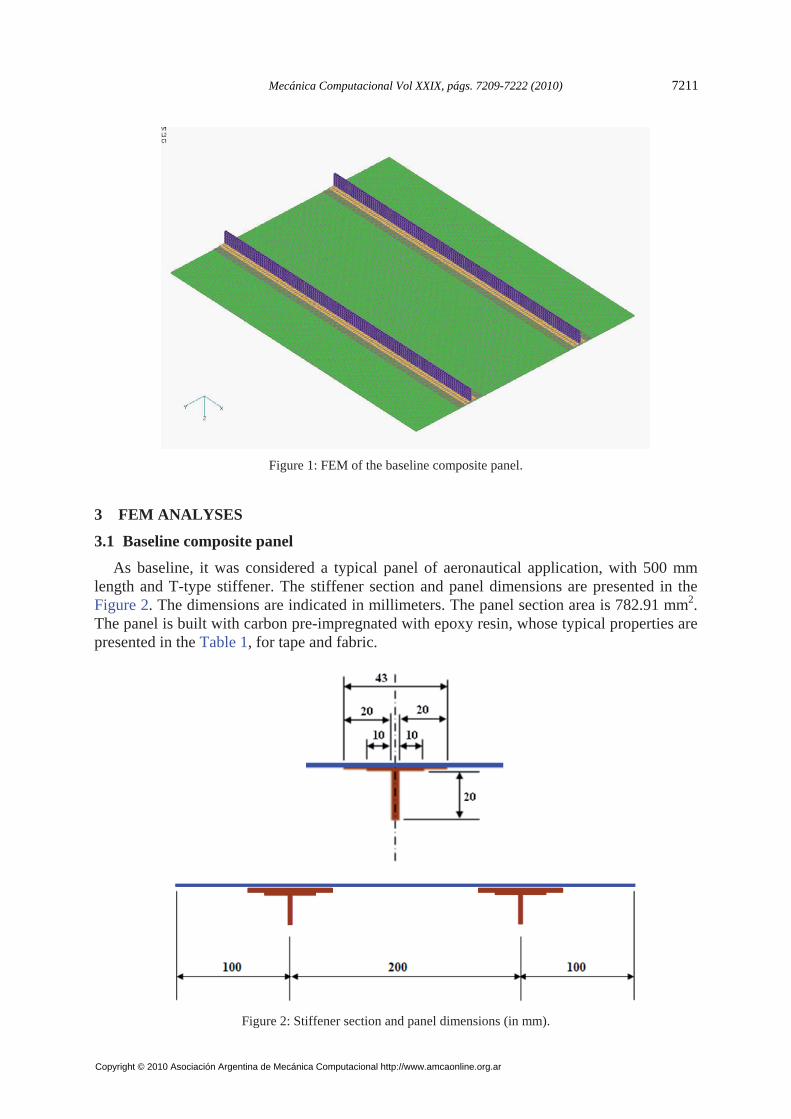
Figure 1: FEM of the baseline composite panel.
3 FEM ANALYSES
3.1 Baseline composite panel
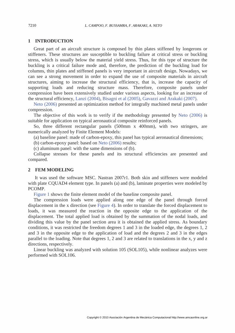
As baseline, it was considered a typical panel of aeronautical application, with 500 mm length and T-type stiffener. The stiffener section and panel dimensions are presented in the Figure 2. The dimensions are indicated in millimeters. The panel section area is 782.91 mm2. The panel is built with carbon pre-impregnated with epoxy resin, whose typical properties are presented in the Table 1, for tape and fabric.
Figure 2: Stiffener section and panel dimensions (in mm).
Mecánica Computacional Vol XXIX, págs. 7209-7222 (2010) 7211
Copyright © 2010 Asociación Argentina de Mecánica Computacional http://www.amcaonline.org.ar
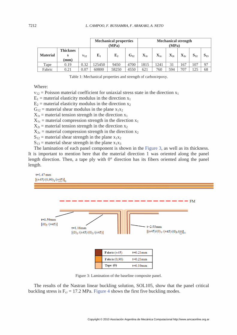
Mechanical properties
(MPa) Mechanical strength
(MPa)
Material Thicknes
s (mm)
12 E1 E2 G12 X1t X1c X2t X2c S12 S13
Tape 0.19 0.32 125450 9450 4700 1815 1241 31 167 107 97 Fabric 0.21 0.07 60800 58250 4550 621 760 594 707 125 68
Table 1: Mechanical properties and strength of carbon/epoxy.
Where: 12 = Poisson material coefficient for uniaxial stress state in the direction x1 E1 = material elasticity modulus in the direction x1 E2 = material elasticity modulus in the direction x2 G12 = material shear modulus in the plane x1x2 X1t = material tension strength in the direction x1 X1c = material compression strength in the direction x1 X2t = material tension strength in the direction x2 X2c = material compression strength in the direction x2 S12 = material shear strength in the plane x1x2 S13 = material shear strength in the plane x1x3 The lamination of each panel component is shown in the Figure 3, as well as its thickness.
It is important to mention here that the material direction 1 was oriented along the panel length direction. Then, a tape ply with 0° direction has its fibers oriented along the panel length.
Figure 3: Lamination of the baseline composite panel.
The results of the Nastran linear buckling solution, SOL105, show that the panel critical buckling stress is Fcr = 17.2 MPa. Figure 4 shows the first five buckling modes.
L. CAMPOO, F. BUSSAMRA, F. ARAKAKI, A. NETO7212
Copyright © 2010 Asociación Argentina de Mecánica Computacional http://www.amcaonline.org.ar
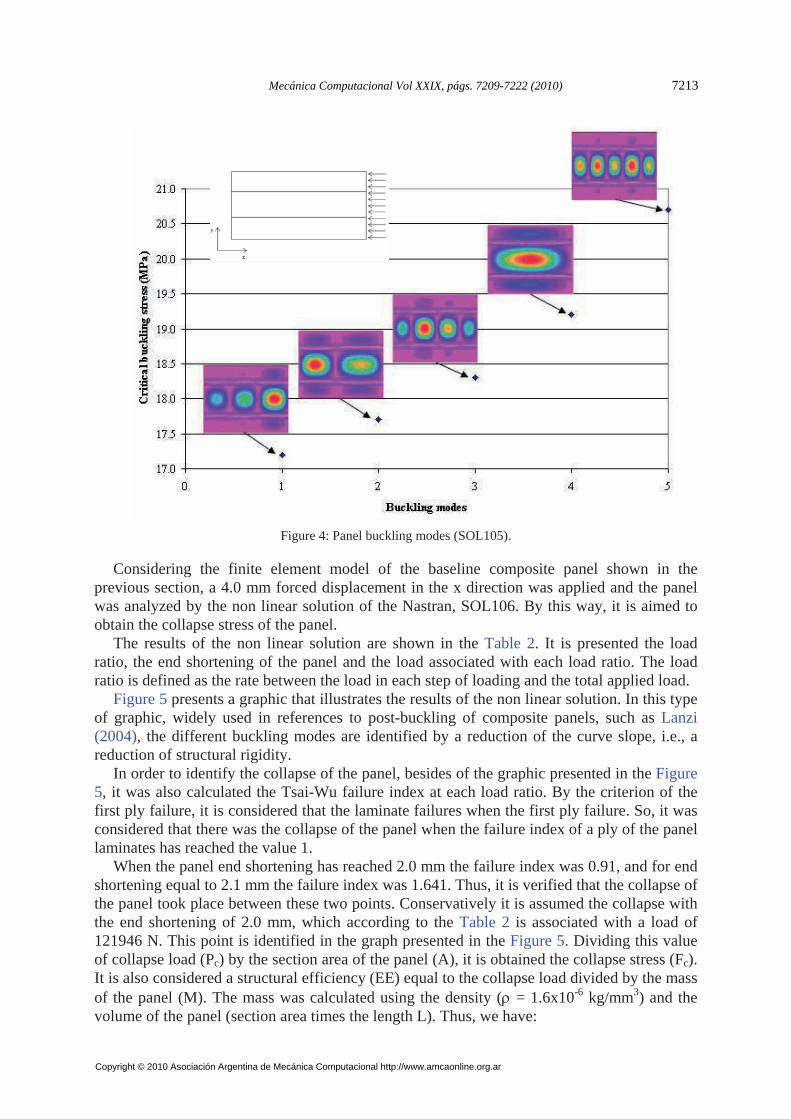
Figure 4: Panel buckling modes (SOL105).
Considering the finite element model of the baseline composite panel shown in the previous section, a 4.0 mm forced displacement in the x direction was applied and the panel was analyzed by the non linear solution of the Nastran, SOL106. By this way, it is aimed to obtain the collapse stress of the panel.
The results of the non linear solution are shown in the Table 2. It is presented the load ratio, the end shortening of the panel and the load associated with each load ratio. The load ratio is defined as the rate between the load in each step of loading and the total applied load.
Figure 5 presents a graphic that illustrates the results of the non linear solution. In this type of graphic, widely used in references to post-buckling of composite panels, such as Lanzi (2004), the different buckling modes are identified by a reduction of the curve slope, i.e., a reduction of structural rigidity.
In order to identify the collapse of the panel, besides of the graphic presented in the Figure 5, it was also calculated the Tsai-Wu failure index at each load ratio. By the criterion of the first ply failure, it is considered that the laminate failures when the first ply failure. So, it was considered that there was the collapse of the panel when the failure index of a ply of the panel laminates has reached the value 1.
When the panel end shortening has reached 2.0 mm the failure index was 0.91, and for end shortening equal to 2.1 mm the failure index was 1.641. Thus, it is verified that the collapse of the panel took place between these two points. Conservatively it is assumed the collapse with the end shortening of 2.0 mm, which according to the Table 2 is associated with a load of 121946 N. This point is identified in the graph presented in the Figure 5. Dividing this value of collapse load (Pc) by the section area of the panel (A), it is obtained the collapse stress (Fc). It is also considered a structural efficiency (EE) equal to the collapse load divided by the mass of the panel (M). The mass was calculated using the density ( = 1.6x10⁻⁶ kg/mm3) and the volume of the panel (section area times the length L). Thus, we have:
Mecánica Computacional Vol XXIX, págs. 7209-7222 (2010) 7213
Copyright © 2010 Asociación Argentina de Mecánica Computacional http://www.amcaonline.org.ar
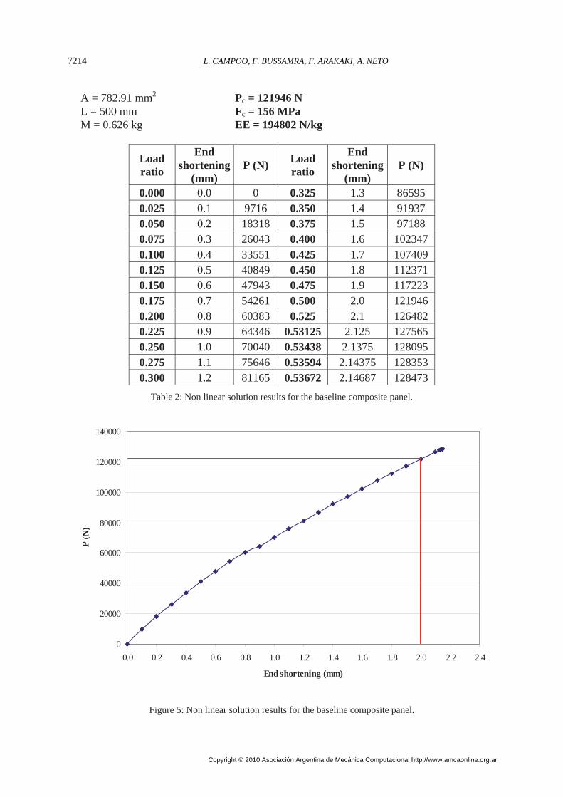
A = 782.91 mm2 Pc = 121946 N L = 500 mm Fc = 156 MPa M = 0.626 kg EE = 194802 N/kg
Load ratio
End shortening
(mm) P (N)
Load ratio
End shortening
(mm) P (N)
0.000 0.0 0 0.325 1.3 86595 0.025 0.1 9716 0.350 1.4 91937 0.050 0.2 18318 0.375 1.5 97188 0.075 0.3 26043 0.400 1.6 102347 0.100 0.4 33551 0.425 1.7 107409 0.125 0.5 40849 0.450 1.8 112371 0.150 0.6 47943 0.475 1.9 117223 0.175 0.7 54261 0.500 2.0 121946 0.200 0.8 60383 0.525 2.1 126482 0.225 0.9 64346 0.53125 2.125 127565 0.250 1.0 70040 0.53438 2.1375 128095 0.275 1.1 75646 0.53594 2.14375 128353 0.300 1.2 81165 0.53672 2.14687 128473
Table 2: Non linear solution results for the baseline composite panel.
0
20000
40000
60000
80000
100000
120000
140000
0.0 0.2 0.4 0.6 0.8 1.0 1.2 1.4 1.6 1.8 2.0 2.2 2.4
End shortening (mm)
P (N
)
Figure 5: Non linear solution results for the baseline composite panel.
L. CAMPOO, F. BUSSAMRA, F. ARAKAKI, A. NETO7214
Copyright © 2010 Asociación Argentina de Mecánica Computacional http://www.amcaonline.org.ar
3.2 Idealized composite panel with the optimal dimensions of Neto (2006)
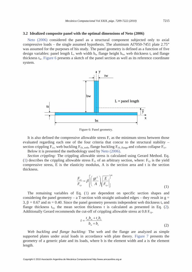
Neto (2006) considered the panel as a structural component subjected only to axial compressive loads – the single assumed hypothesis. The aluminum Al7050-7451 plate 2.75” was assumed for the purposes of his study. The panel geometry is defined as a function of five design variables: panel length L, web width bs, flange height bw, web thickness ts and flange thickness tw. Figure 6 presents a sketch of the panel section as well as its reference coordinate system.
y
bs
ts
tw
bw
x
y
L = panel length
y
bs
ts
tw
bw
x
y
L = panel length
Figure 6: Panel geometry.
It is also defined the compressive allowable stress Fc as the minimum stress between those evaluated regarding each one of the four criteria that concur to the structural stability – section crippling Fcc, web buckling Fcb_web, flange buckling Fcb_flange and column collapse Fcr.
Below it is presented the methodology used by Neto (2006). Section crippling: The crippling allowable stress is calculated using Gerard Method. Eq.
(1) describes the crippling allowable stress Fcc of an arbitrary section, where: Fcy is the yield compressive stress, E is the elasticity modulus, A is the section area and t is the section thickness.
m
cycy
cc
F
E
A
gt
F
F
2
(1)
The remaining variables of Eq. (1) are dependent on specific section shapes and considering the panel geometry – a T-section with straight unloaded edges – they result in g = 3, = 0.67 and m = 0.40. Since the panel geometry presents independent web thickness ts and flange thickness tw, the mean section thickness t is calculated as presented in Eq. (2). Additionally Gerard recommends the cut-off of crippling allowable stress at 0.8 Fcy.
sw
ssww
bb
btbtt
(2)
Web buckling and flange buckling: The web and the flange are analyzed as simple supported plates under axial loads in accordance with plate theory. Figure 7 presents the geometry of a generic plate and its loads, where b is the element width and a is the element length.
Mecánica Computacional Vol XXIX, págs. 7209-7222 (2010) 7215
Copyright © 2010 Asociación Argentina de Mecánica Computacional http://www.amcaonline.org.ar
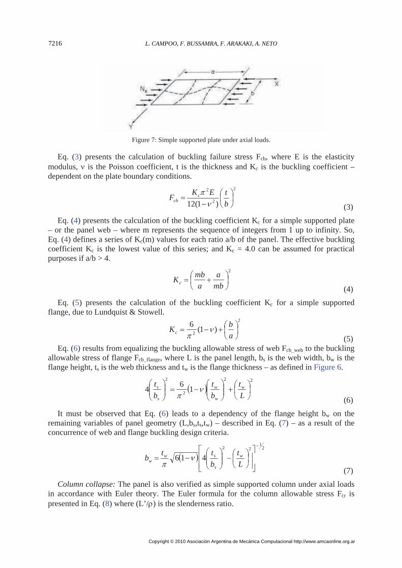
Figure 7: Simple supported plate under axial loads.
Eq. (3) presents the calculation of buckling failure stress Fcb, where E is the elasticity modulus, is the Poisson coefficient, t is the thickness and Kc is the buckling coefficient – dependent on the plate boundary conditions.
2
2
2
)1(12
b
tEKF c
cb
(3)
Eq. (4) presents the calculation of the buckling coefficient Kc for a simple supported plate – or the panel web – where m represents the sequence of integers from 1 up to infinity. So, Eq. (4) defines a series of Kc(m) values for each ratio a/b of the panel. The effective buckling coefficient Kc is the lowest value of this series; and Kc = 4.0 can be assumed for practical purposes if a/b > 4.
2
mb
a
a
mbKc
(4)
Eq. (5) presents the calculation of the buckling coefficient Kc for a simple supported flange, due to Lundquist & Stowell.
2
2)1(
6
a
bKc
(5) Eq. (6) results from equalizing the buckling allowable stress of web Fcb_web to the buckling
allowable stress of flange Fcb_flange, where L is the panel length, bs is the web width, bw is the flange height, ts is the web thickness and tw is the flange thickness – as defined in Figure 6.
22
2
2
16
4
L
t
b
t
b
t w
w
w
s
s (6)
It must be observed that Eq. (6) leads to a dependency of the flange height bw on the remaining variables of panel geometry (L,bs,ts,tw) – described in Eq. (7) – as a result of the concurrence of web and flange buckling design criteria.
2
122
416
L
t
b
ttb w
s
sww
(7)
Column collapse: The panel is also verified as simple supported column under axial loads in accordance with Euler theory. The Euler formula for the column allowable stress Fcr is presented in Eq. (8) where (L’/) is the slenderness ratio.
L. CAMPOO, F. BUSSAMRA, F. ARAKAKI, A. NETO7216
Copyright © 2010 Asociación Argentina de Mecánica Computacional http://www.amcaonline.org.ar
2
2
'
L
EFcr
(8)
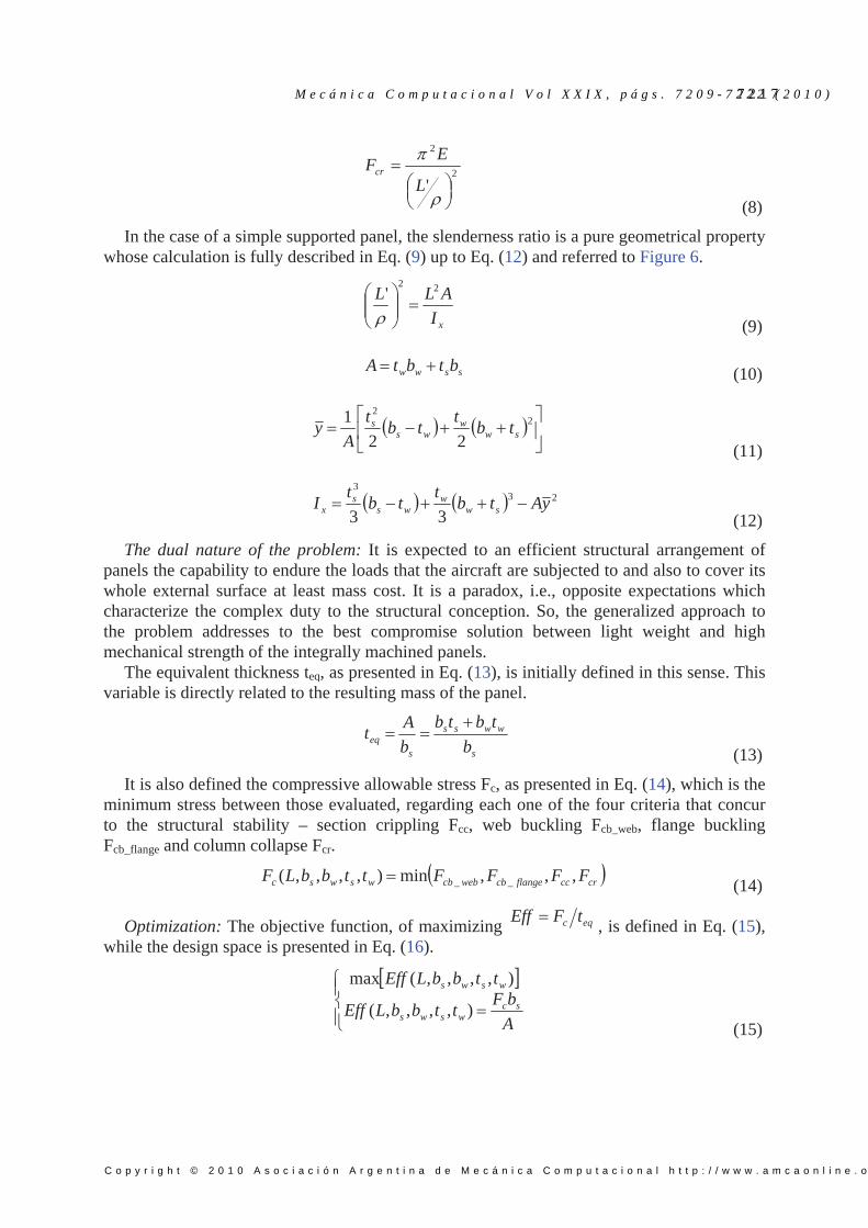
In the case of a simple supported panel, the slenderness ratio is a pure geometrical property whose calculation is fully described in Eq. (9) up to Eq. (12) and referred to Figure 6.
xI
ALL 22'
(9)
ssww btbtA (10)
2
2
22
1sw
wws
s tbt
tbt
Ay
(11)
233
33yAtb
ttb
tI sw
wws
sx
(12)
The dual nature of the problem: It is expected to an efficient structural arrangement of panels the capability to endure the loads that the aircraft are subjected to and also to cover its whole external surface at least mass cost. It is a paradox, i.e., opposite expectations which characterize the complex duty to the structural conception. So, the generalized approach to the problem addresses to the best compromise solution between light weight and high mechanical strength of the integrally machined panels.
The equivalent thickness teq, as presented in Eq. (13), is initially defined in this sense. This variable is directly related to the resulting mass of the panel.
s
wwss
seq b
tbtb
b
At
(13)
It is also defined the compressive allowable stress Fc, as presented in Eq. (14), which is the minimum stress between those evaluated, regarding each one of the four criteria that concur to the structural stability – section crippling Fcc, web buckling Fcb_web, flange buckling Fcb_flange and column collapse Fcr.
crccflangecbwebcbwswsc FFFFttbbLF ,,,min),,,,( __ (14)
Optimization: The objective function, of maximizing eqc tFEff , is defined in Eq. (15),
while the design space is presented in Eq. (16).
A
bFttbbLEff
ttbbLEff
scwsws
wsws
),,,,(
),,,,(max
(15)
M e c á n i c a C o m p u t a c i o n a l V o l X X I X , p á g s . 7 2 0 9 - 7 2 2 2 ( 2 0 1 0 )7 2 1 7
C o p y r i g h t © 2 0 1 0 A s o c i a c i ó n A r g e n t i n a d e M e c á n i c a C o m p u t a c i o n a l h t t p : / / w w w . a m c a o n l i n e . o r g . a r
sws
sss
s
ttt
btb
LbL
25.0
2.0005.0
4.01.0
(16)
It must be observed that Eq. (15) enables the panel geometry to reach the best compromise solution between the maximum compressive allowable stress and the minimum mass, keeping coherence with the purposes of the dual nature of the problem.
The optimization results are presented in Neto (2006). The set of results characterizes the panel geometry (tw/ts, ts/bs and tw/ts) and its respective compressive allowable stress Fc for each given value to the design parameter bs/L.
Here, in this item, it is intended to build a composite panel with the optimal dimensions presented in the work of Neto (2006) and to evaluate its collapse stress. This collapse stress will be compared with those of the baseline panel and the one obtained to the metallic panel with same geometry.
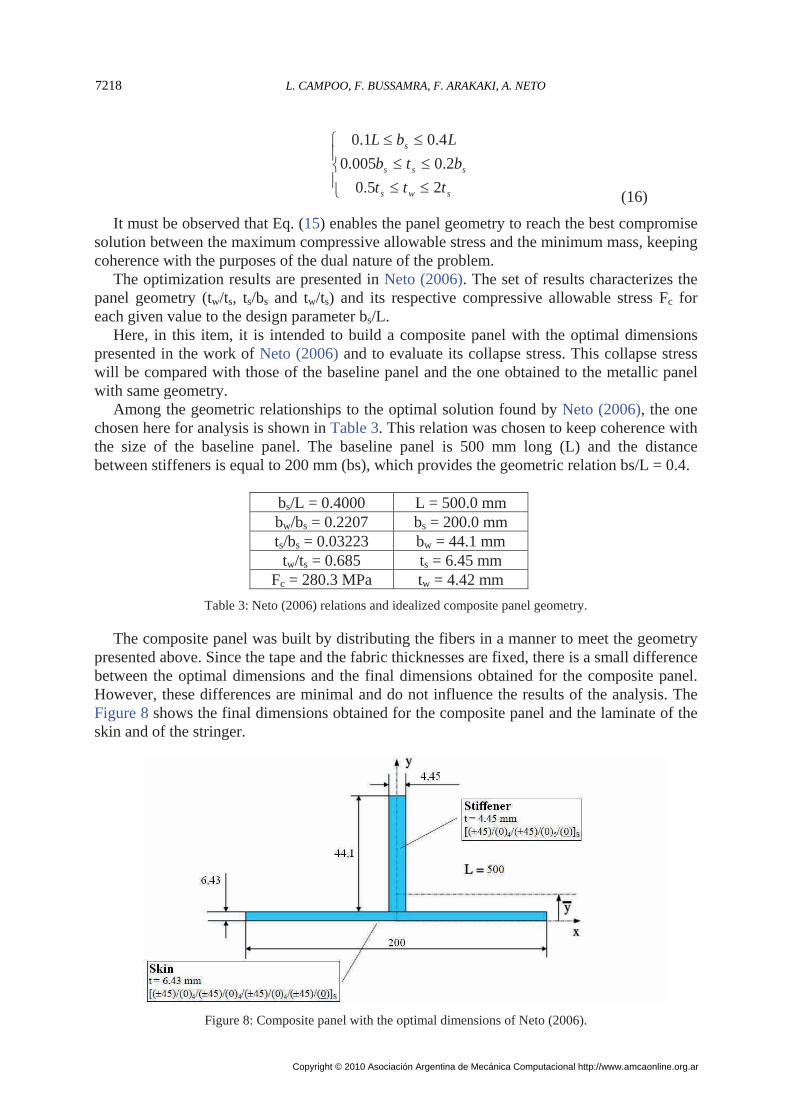
Among the geometric relationships to the optimal solution found by Neto (2006), the one chosen here for analysis is shown in Table 3. This relation was chosen to keep coherence with the size of the baseline panel. The baseline panel is 500 mm long (L) and the distance between stiffeners is equal to 200 mm (bs), which provides the geometric relation bs/L = 0.4.
bs/L = 0.4000 L = 500.0 mm bw/bs = 0.2207 bs = 200.0 mm ts/bs = 0.03223 bw = 44.1 mm tw/ts = 0.685 ts = 6.45 mm
Fc = 280.3 MPa tw = 4.42 mm
Table 3: Neto (2006) relations and idealized composite panel geometry.
The composite panel was built by distributing the fibers in a manner to meet the geometry presented above. Since the tape and the fabric thicknesses are fixed, there is a small difference between the optimal dimensions and the final dimensions obtained for the composite panel. However, these differences are minimal and do not influence the results of the analysis. The Figure 8 shows the final dimensions obtained for the composite panel and the laminate of the skin and of the stringer.
Figure 8: Composite panel with the optimal dimensions of Neto (2006).
L. CAMPOO, F. BUSSAMRA, F. ARAKAKI, A. NETO7218
Copyright © 2010 Asociación Argentina de Mecánica Computacional http://www.amcaonline.org.ar
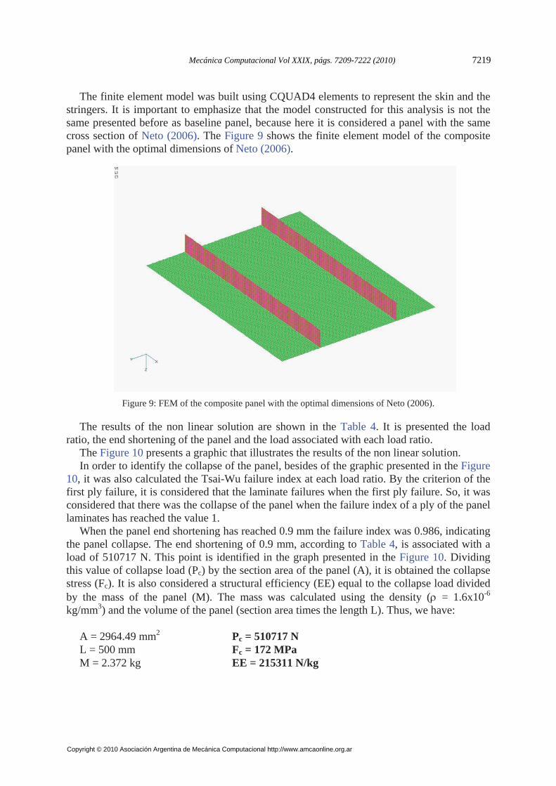
The finite element model was built using CQUAD4 elements to represent the skin and the stringers. It is important to emphasize that the model constructed for this analysis is not the same presented before as baseline panel, because here it is considered a panel with the same cross section of Neto (2006). The Figure 9 shows the finite element model of the composite panel with the optimal dimensions of Neto (2006).
Figure 9: FEM of the composite panel with the optimal dimensions of Neto (2006).
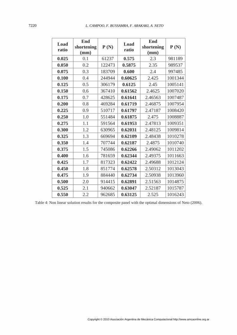
The results of the non linear solution are shown in the Table 4. It is presented the load ratio, the end shortening of the panel and the load associated with each load ratio.
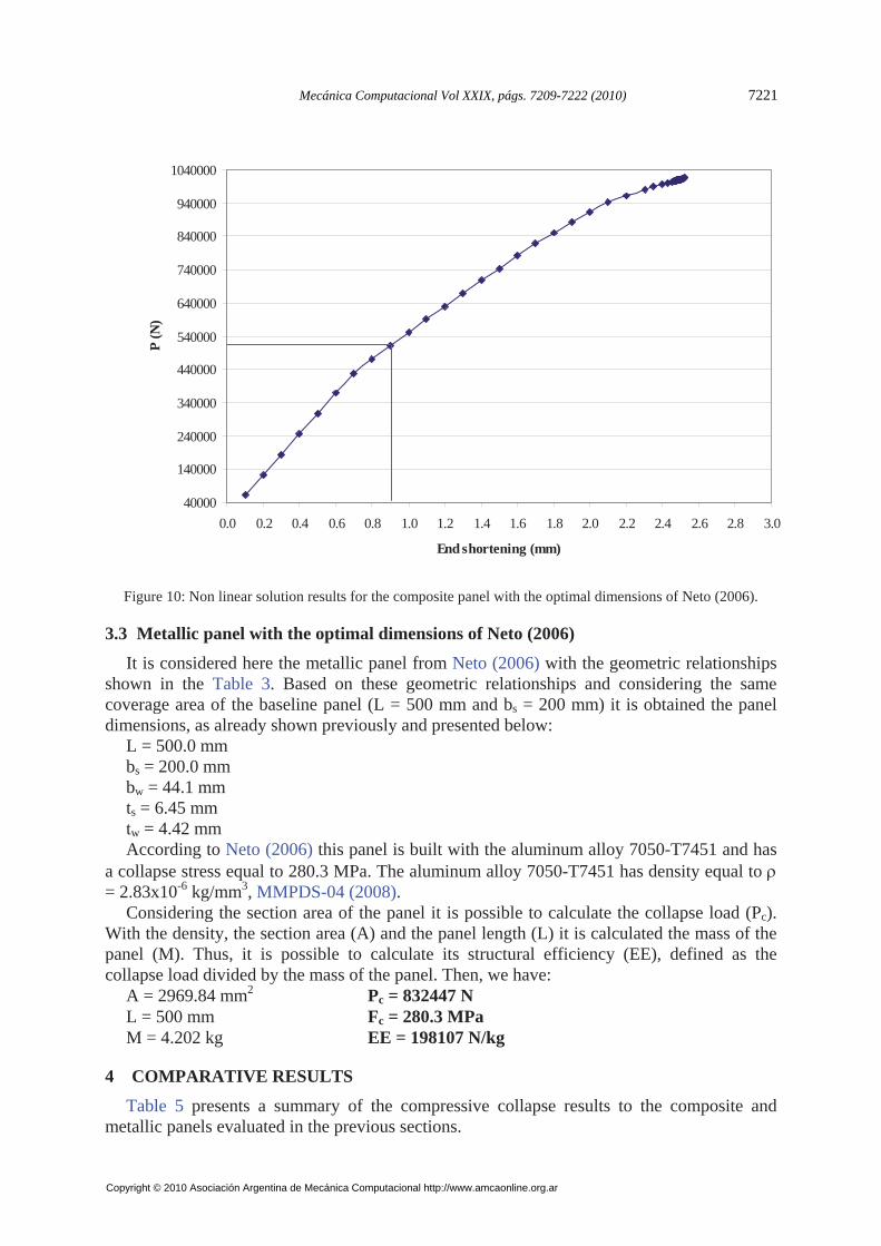
The Figure 10 presents a graphic that illustrates the results of the non linear solution. In order to identify the collapse of the panel, besides of the graphic presented in the Figure
10, it was also calculated the Tsai-Wu failure index at each load ratio. By the criterion of the first ply failure, it is considered that the laminate failures when the first ply failure. So, it was considered that there was the collapse of the panel when the failure index of a ply of the panel laminates has reached the value 1.
When the panel end shortening has reached 0.9 mm the failure index was 0.986, indicating the panel collapse. The end shortening of 0.9 mm, according to Table 4, is associated with a load of 510717 N. This point is identified in the graph presented in the Figure 10. Dividing this value of collapse load (Pc) by the section area of the panel (A), it is obtained the collapse stress (Fc). It is also considered a structural efficiency (EE) equal to the collapse load divided by the mass of the panel (M). The mass was calculated using the density ( = 1.6x10⁻⁶ kg/mm3) and the volume of the panel (section area times the length L). Thus, we have:
A = 2964.49 mm2 Pc = 510717 N L = 500 mm Fc = 172 MPa M = 2.372 kg EE = 215311 N/kg
Mecánica Computacional Vol XXIX, págs. 7209-7222 (2010) 7219
Copyright © 2010 Asociación Argentina de Mecánica Computacional http://www.amcaonline.org.ar
Load ratio
End shortening
(mm) P (N)
Load ratio
End shortening
(mm) P (N)
0.025 0.1 61237 0.575 2.3 981189 0.050 0.2 122473 0.5875 2.35 989537 0.075 0.3 183709 0.600 2.4 997485 0.100 0.4 244944 0.60625 2.425 1001344 0.125 0.5 306179 0.6125 2.45 1005141 0.150 0.6 367410 0.61562 2.4625 1007020 0.175 0.7 428625 0.61641 2.46563 1007487 0.200 0.8 469284 0.61719 2.46875 1007954 0.225 0.9 510717 0.61797 2.47187 1008420 0.250 1.0 551484 0.61875 2.475 1008887 0.275 1.1 591564 0.61953 2.47813 1009351 0.300 1.2 630965 0.62031 2.48125 1009814 0.325 1.3 669694 0.62109 2.48438 1010278 0.350 1.4 707744 0.62187 2.4875 1010740 0.375 1.5 745086 0.62266 2.49062 1011202 0.400 1.6 781659 0.62344 2.49375 1011663 0.425 1.7 817323 0.62422 2.49688 1012124 0.450 1.8 851774 0.62578 2.50312 1013043 0.475 1.9 884440 0.62734 2.50938 1013960 0.500 2.0 914415 0.62891 2.51563 1014875 0.525 2.1 940662 0.63047 2.52187 1015787 0.550 2.2 962685 0.63125 2.525 1016243
Table 4: Non linear solution results for the composite panel with the optimal dimensions of Neto (2006).
L. CAMPOO, F. BUSSAMRA, F. ARAKAKI, A. NETO7220
Copyright © 2010 Asociación Argentina de Mecánica Computacional http://www.amcaonline.org.ar
40000
140000
240000
340000
440000
540000
640000
740000
840000
940000
1040000
0.0 0.2 0.4 0.6 0.8 1.0 1.2 1.4 1.6 1.8 2.0 2.2 2.4 2.6 2.8 3.0
End shortening (mm)
P (N
)
Figure 10: Non linear solution results for the composite panel with the optimal dimensions of Neto (2006).
3.3 Metallic panel with the optimal dimensions of Neto (2006)
It is considered here the metallic panel from Neto (2006) with the geometric relationships shown in the Table 3. Based on these geometric relationships and considering the same coverage area of the baseline panel (L = 500 mm and bs = 200 mm) it is obtained the panel dimensions, as already shown previously and presented below:
L = 500.0 mm bs = 200.0 mm bw = 44.1 mm ts = 6.45 mm tw = 4.42 mm According to Neto (2006) this panel is built with the aluminum alloy 7050-T7451 and has
a collapse stress equal to 280.3 MPa. The aluminum alloy 7050-T7451 has density equal to = 2.83x10⁻⁶ kg/mm3, MMPDS-04 (2008).
Considering the section area of the panel it is possible to calculate the collapse load (Pc). With the density, the section area (A) and the panel length (L) it is calculated the mass of the panel (M). Thus, it is possible to calculate its structural efficiency (EE), defined as the collapse load divided by the mass of the panel. Then, we have:
A = 2969.84 mm2 Pc = 832447 N L = 500 mm Fc = 280.3 MPa M = 4.202 kg EE = 198107 N/kg
4 COMPARATIVE RESULTS
Table 5 presents a summary of the compressive collapse results to the composite and metallic panels evaluated in the previous sections.
Mecánica Computacional Vol XXIX, págs. 7209-7222 (2010) 7221
Copyright © 2010 Asociación Argentina de Mecánica Computacional http://www.amcaonline.org.ar
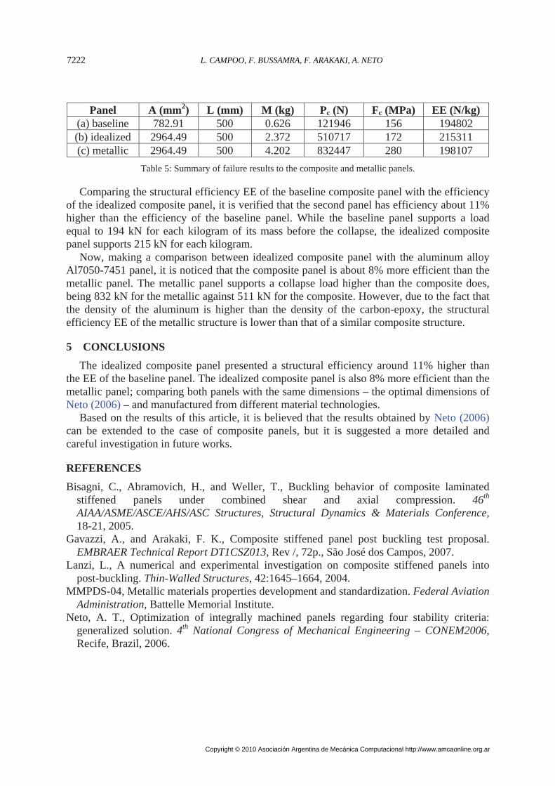
Panel A (mm2) L (mm) M (kg) Pc (N) Fc (MPa) EE (N/kg)
(a) baseline 782.91 500 0.626 121946 156 194802 (b) idealized 2964.49 500 2.372 510717 172 215311 (c) metallic 2964.49 500 4.202 832447 280 198107
Table 5: Summary of failure results to the composite and metallic panels.
Comparing the structural efficiency EE of the baseline composite panel with the efficiency of the idealized composite panel, it is verified that the second panel has efficiency about 11% higher than the efficiency of the baseline panel. While the baseline panel supports a load equal to 194 kN for each kilogram of its mass before the collapse, the idealized composite panel supports 215 kN for each kilogram.
Now, making a comparison between idealized composite panel with the aluminum alloy Al7050-7451 panel, it is noticed that the composite panel is about 8% more efficient than the metallic panel. The metallic panel supports a collapse load higher than the composite does, being 832 kN for the metallic against 511 kN for the composite. However, due to the fact that the density of the aluminum is higher than the density of the carbon-epoxy, the structural efficiency EE of the metallic structure is lower than that of a similar composite structure.
5 CONCLUSIONS
The idealized composite panel presented a structural efficiency around 11% higher than the EE of the baseline panel. The idealized composite panel is also 8% more efficient than the metallic panel; comparing both panels with the same dimensions – the optimal dimensions of Neto (2006) – and manufactured from different material technologies.
Based on the results of this article, it is believed that the results obtained by Neto (2006) can be extended to the case of composite panels, but it is suggested a more detailed and careful investigation in future works.
REFERENCES
Bisagni, C., Abramovich, H., and Weller, T., Buckling behavior of composite laminated stiffened panels under combined shear and axial compression. 46th AIAA/ASME/ASCE/AHS/ASC Structures, Structural Dynamics & Materials Conference, 18-21, 2005.
Gavazzi, A., and Arakaki, F. K., Composite stiffened panel post buckling test proposal. EMBRAER Technical Report DT1CSZ013, Rev /, 72p., São José dos Campos, 2007.
Lanzi, L., A numerical and experimental investigation on composite stiffened panels into post-buckling. Thin-Walled Structures, 42:1645–1664, 2004.
MMPDS-04, Metallic materials properties development and standardization. Federal Aviation Administration, Battelle Memorial Institute.
Neto, A. T., Optimization of integrally machined panels regarding four stability criteria: generalized solution. 4th National Congress of Mechanical Engineering – CONEM2006, Recife, Brazil, 2006.
L. CAMPOO, F. BUSSAMRA, F. ARAKAKI, A. NETO7222
Copyright © 2010 Asociación Argentina de Mecánica Computacional http://www.amcaonline.org.ar