numerical over current / earth fault protection relay...
TRANSCRIPT

NUMERICAL OC/EF PROTECTION RELAY ADR141C/241C
ASHIDA Electronics Pvt. Ltd. Ref: Manual / ADR141C / 241C Issue: 04 Date : 15.11.2010
Page 1/79
Numerical
Over Current / Earth Fault
Protection Relay
Type : ADR141C / 241C

NUMERICAL OC/EF PROTECTION RELAY ADR141C/241C
ASHIDA Electronics Pvt. Ltd. Ref: Manual / ADR141C / 241C Issue: 04 Date : 15.11.2010
Page 2/79
User Notice
Ashida Electronics (P) Ltd. Reserve all right to make improvements in the
products described in this manual at any time and without notice. All rights are
reserved. No part of this manual may be reproduce, copied, translated or
transmitted in any form or by any means without the prior written permission of
Ashida Electronics (p.) Ltd. Information in this manual is intended to be accurate
and reliable. However Ashida assumes no responsibility for its use; nor for any
infringements of rights of third parties, which may result from its use.

NUMERICAL OC/EF PROTECTION RELAY ADR141C/241C
ASHIDA Electronics Pvt. Ltd. Ref: Manual / ADR141C / 241C Issue: 04 Date : 15.11.2010
Page 3/79
Contents
1. Description 6
2. Protection Feature 7
3. Relay Design Feature 7
4. Main Function 7
4.1 Over current and EF Element 7
4.2 Inverse Time curve 8
4.3 Trip circuit supervision 9
4.4 Breaker failure detection 9
4.5 Cold Load Setting 10
5. Construction Detail 10
6. Self Check Feature 10
7. Technical Details 11
7.1 Technical Specification 11
7.2 Type Test Detail 13
7.3 Cabinet Drawing 15
7.4 Block Diagram 16
8 Front Panel and Control 17
8.1 User’s Interface 18
8.1.1 LCD Display 18
8.1.2 Touch Keys 18
8.1.3 LED’s 19
8.2 Password 19
8.2.1 Password Entry & Changing the Password 19
8.2.2 Clear Password 21
8.3 Menus 22
8.3.1 Default Display 22
8.3.2 Main Menu List 22
8.3.2.1 Main Menu List Details 23
8.3.3 Primary Current 25
8.3.3.1 To View – Primary Current 25
8.3.4 General Setting 26
8.3.4.1 To Set – General Setting 26
8.3.4.2 To View – General Setting 28

NUMERICAL OC/EF PROTECTION RELAY ADR141C/241C
ASHIDA Electronics Pvt. Ltd. Ref: Manual / ADR141C / 241C Issue: 04 Date : 15.11.2010
Page 4/79
8.3.5 Relay Setting 29
8.3.5.1 To Set – Relay Setting 29
8.3.5.2 To View – Relay Setting 32
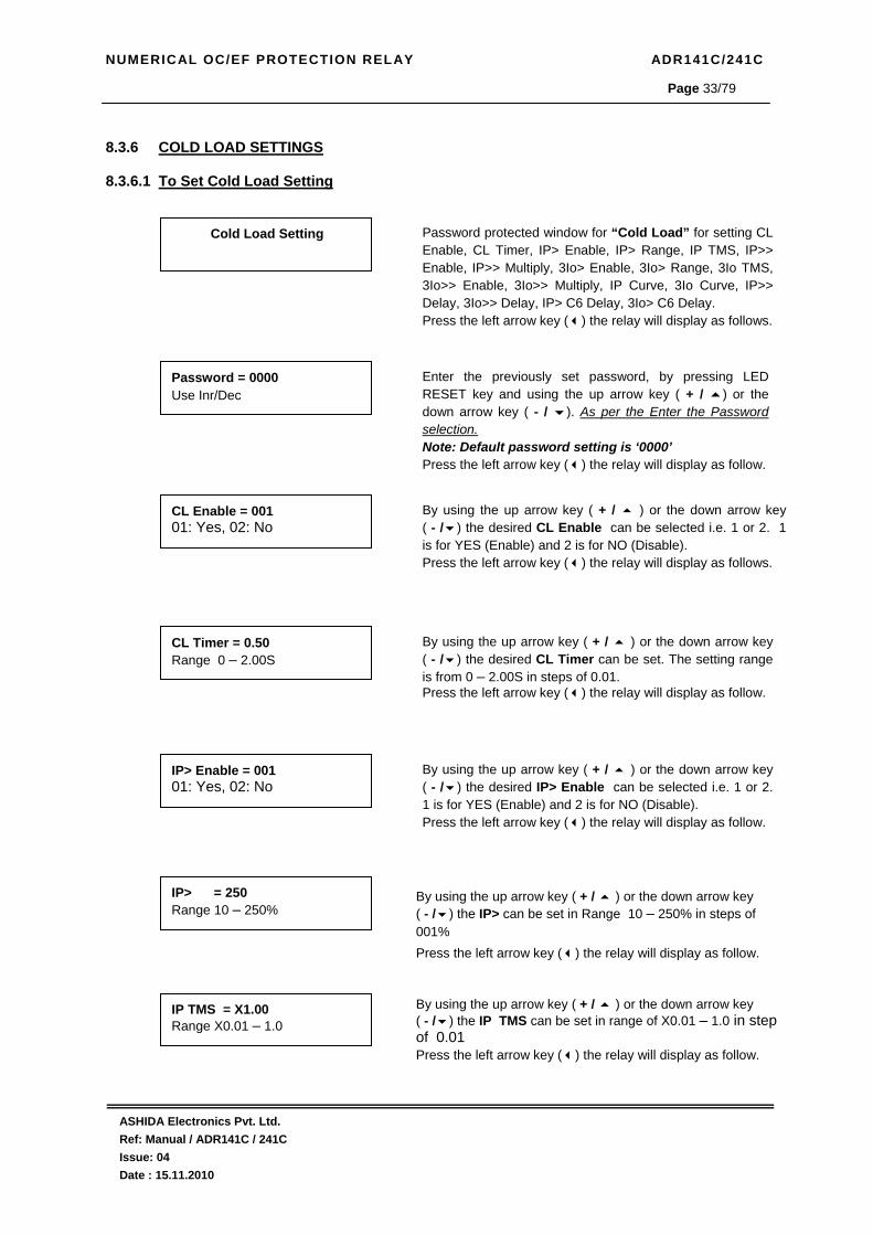
8.3.6 Cold Load Settings 33
8.3.6.1 To Set – Cold Load Setting 33
8.3.6.2 To View – Cold Load Setting 36
8.3.7 Relay/LED Configuration 37
8.3.7.1 Bit Definition for Relay/LED Configuration 37
8.3.7.2 To Set – Relay/LED Configuration 40
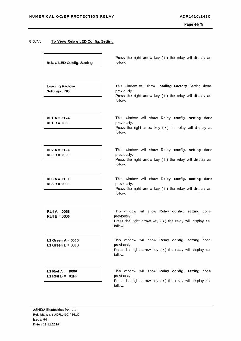
8.3.7.3 To View – Relay/LED Configuration 44
8.3.8 Trip Test 46
8.3.8.1 To View – Trip Test 46
8.3.9 Fault 1 47
8.3.9.1 To View – Fault 1 Data [Fault 2 to Fault 10] 47
8.3.10 Error Log 48
8.3.10.1 To View – Error Log 48
8.3.11 Status 48
8.3.11.1 To View – Status 48
8.3.12 Date Time Setting 49
8.3.12.1 To Set – Date Time setting 49
8.3.12.2 To View – Date Time Setting 50
8.3.13 Secondary Current 50
8.3.13.1 To View – Secondary Current 50
9.0 Menu Content Table 51
9.1 To View Primary Current 51
9.2 To Set / View General Settings 52
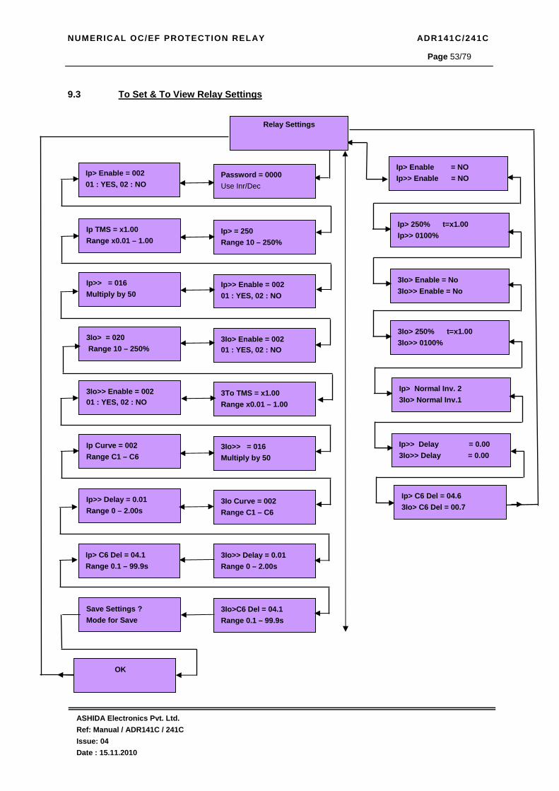
9.3 To Set / View Relay Settings 53
9.4 To Set / View Cold Load Settings 54
9.5 To Set / View Relay/LEDs Settings 55
9.6 To View Trip Test Settings 56
9.7 To View Fault 1 (Fault 2 – Fault 5) 57
9.8 To View Error Log Settings 58
9.9 To View Status Settings 58
9.10 To Set / View Date/Time Settings 59
9.11 To View Secondary Current 60

NUMERICAL OC/EF PROTECTION RELAY ADR141C/241C
ASHIDA Electronics Pvt. Ltd. Ref: Manual / ADR141C / 241C Issue: 04 Date : 15.11.2010
Page 5/79
10 Communication - Only for ADR241C Relay 61
10.1 General 61
10.2 General Questions 62
10.3 Physical connection and link layer 63
10.4 Relay Talk System for downloading the data 64
10.5 ADR241C IED Main Screen 68
10.5.1 Parameter Display 69
10.5.2 IEDs Din Display 69
10.5.3 Control Operation 70
10.5.4 Private Setting 70
10.6 History Fault 71
10.7 Setting 72
10.7.1 General Setting 72
10.7.2 Bank Settings 73
10.8 Event List 74
11.0 Test Report Annexure – 1 76
11.1 Drawing for Test Setup. 78 12.0 Revision Note 79

NUMERICAL OC/EF PROTECTION RELAY ADR141C/241C
ASHIDA Electronics Pvt. Ltd. Ref: Manual / ADR141C / 241C Issue: 04 Date : 15.11.2010
Page 6/79
1. Description:
• ADR141C / ADR241C are second generation Numerical 3OC + 1EF Over Current
Relay. [The ADR241C is communicable Relay having RS422 Port. All the other features as per ADR141C Relay] It consist all the necessary protection and monitoring
functions required for Normal feeder. It consists of High Speed Digital DSP Controller.
• Analog Measuring Module.
• Power supply Module.
• Digital Input output module.
The High speed Digital Signal Controller continuously monitors phase, E/F current along with
different optical isolated status connections. The high-speed micro-controller samples these
current signals through a A/D converter. The Digital Signal performs powerful Numerical Algorithms to find out RMS of fundamental & harmonic contents of the current then this
value is used for protection and metering function. All measurement is tuned to fundamental
frequency i.e. 50Hz, thus relay remain stable during distorted waveform generated
electronics loco-motive. All these measure values are then used for different protection
function such as IDMT/DMT Over current protection, Instantaneous Over current protection,
Earth Fault protection, etc. These measured values are also displayed on large 16 x 2 LCD
display for metering purpose. The DSC also monitors different digital input through optical
isolator and perform some monitoring function such trip circuit supervision, and control
potential free contact for control CB and generate ALARM and Tele-signalling.
The power supply module is basically DC – DC converted designed using modern PWM
based Switching mode technique to convert station battery supply to the 12V and 24Vdc low
voltage supply for relay electronics and control circuit. It also provides necessary isolation
from station battery. The power supply module is design using very advance PWM controller
which allow very wide input supply variation i.e 18V to 250VAC/DC covering 24Vdc, 30Vdc,
and 110Vdc and 220Vdc station battery requirement.
The relay is having total 4 nos of high intensity dual LED for easy identification of type of fault
for easy user interface. All LEDs and control output RL2 to RL4 are fully programmable via
keypad interface

NUMERICAL OC/EF PROTECTION RELAY ADR141C/241C
ASHIDA Electronics Pvt. Ltd. Ref: Manual / ADR141C / 241C Issue: 04 Date : 15.11.2010
Page 7/79
2. Protection Features:
4 Element (3 Phase + EF) Non Directional Over current IDMT/DMT.
Selection of Curve: Five selectable curve (Normal Inverse1 (C1), Normal Inverse2, (C2)
Very inverse (C3), Extremely inverse (C4), Long time inverse (C5)) and Define Time (C6)
Instantaneous Over-Current Protection with adjustable timer.
Breaker Failure detection
In-built CB Trip Circuit Supervision function during pre closing and post closing of CB.
On site CT Secondary selection 1A or 5A.
Internal calculation of zero seq. current (3Io) for Earth fault.
Wide range Power supply input 18V to 250V AC/DC.
Cold Load Pickup.
RS422 communication Port with IEC 60870-5-103 protocol. [Only in ADR241C]
3. Relay Design Features:
16 x 2 LCD Backlit display for Parameter and setting display.
Online display of CB status and other digital and logical status.
Continuous monitoring of module’s internal hardware and alarm generation in case of
failure of any critical components.
4 Digital Output contacts for local alarm as Trip.
2 dedicated status input for Trip Circuit Monitoring.
5 nos of Fault data stored with keypad interface and time stamping.
4. Main Functions:
The ADR141C are having following protection functions.
1. Non Directional phase Over current element. (Ip>, and Ip>> )
2. Non Directional 3Io (Internally derived EF) (3Io> and 3Io>>).
3. Trip Circuit Super vision.
4. Breaker Failure Detection.
5. Monitoring Functions.
Each of these functions are independently programmable and can be enable or disable by
user depending upon requirement.
4.1 Over Current & EF Element:
The ADR141C is member of Ashida Numerical Relay family design for protection general
feeder. The relay has one stage of IDMT/DMT setting and one stage of instantaneous setting.
(Ip>, IP>>, 3Io>, 3Io>>). All major international IDMT curves are available. Range for first
stage is 10% to 250% and 50% to 3000% for instantaneous stage for phase and 3Io.
Although the curves tend towards infinite when the current approaches Is (general threshold),
the minimum guaranteed value of the operating current for all the curves with the inverse time
characteristic is 1.1Is (with a tolerance of ± 0.05Is).

NUMERICAL OC/EF PROTECTION RELAY ADR141C/241C
ASHIDA Electronics Pvt. Ltd. Ref: Manual / ADR141C / 241C Issue: 04 Date : 15.11.2010
Page 8/79
4.2 Inverse Time Curves :-
The each stage thresholds for phase (earth) over current can be selected with an Inverse
Definite Minimum Time (IDMT) characteristic. The time delay is calculated with a
mathematical formula
Curve Type Description a b C1 Standard Inverse_1 0.14 0.02 C2 Standard Inverse_2 0.60 0.02 C3 Very Inverse 13.5 1 C4 Extremely inverse 80 2 C5 Long Time Inverse 120 1 C6 Define Time - -
K * aI
Iref
b1
t =K * aI
Iref
b1
t =K * aI
Iref
I
Iref
b1
t =K * aI
Iref
b1
t =K * aI
Iref
b1
t =K * aI
Iref
I
Iref
b1
t =

NUMERICAL OC/EF PROTECTION RELAY ADR141C/241C
ASHIDA Electronics Pvt. Ltd. Ref: Manual / ADR141C / 241C Issue: 04 Date : 15.11.2010
Page 9/79
4.3 Trip circuit Supervision:-
The ADR141C is having 2 separate digital opto-coupler status input which can be used to
continuously monitor continuity of trip-circuit. The general scheme is as shown in fig. 4.
Relay monitor Trip coil continuity through CB NO during close condition and through CB NC
during Trip condition. If any discontinuity observed it generate Alarm signal.
The output can be assigned to any of 4 relay RL1 to RL4, The Trip circuit supervision logic
set reset PROTH (Protection healthy) bit, it normally ON and become OFF at following
condition
When DC supply is not sufficient (DC fail)
When CB NO and CB NC both active or both inactive. CB NO as well as CB NC are both
close or open.
Relay detects any internal hard ware Error.
B+
B-
TC
CB NO
CB NC
To Relay CPU
To Relay CPU
TCCOMB+
B-
TC
CB NO
CB NC
Trip Circuit Logic
-
CB NO
-
12
12
6
6
B+
B-
TC
CB NO
CB NC
To Relay CPU
To Relay CPU
TCCOMB+
B-
TC
CB NO
CB NC
Trip Circuit Logic
-
CB NO
-
12
12
6
6
4.4 Breaker Failure Detection:-
Normally after tripping current should become Zero within 100 – 200ms time depend upon
type of fault and breaker mechanism. After Fault ADR141C trigger internal timer (settable
from 50ms to 800ms) if fault is not cleared during this time then relay declare as Breaker fail
(LBB function) and set BF bit. This bit can be assigned to any of the output relay.
Breaker Fail Logic
OPERATIONBF
&&
DELAY 50ms to 800ms TRIP
GENERAL
BF ENABLE
Breaker Fail Logic
OPERATIONBF
&&
DELAY 50ms to 800ms TRIP
GENERAL
BF ENABLE

NUMERICAL OC/EF PROTECTION RELAY ADR141C/241C
ASHIDA Electronics Pvt. Ltd. Ref: Manual / ADR141C / 241C Issue: 04 Date : 15.11.2010
Page 10/79
4.5 Cold Load pickup:-
When the Circuit breaker is closed on load, A load current take sudden inrush current. This
inrush current may be more than 4 to 5 times of rated load current. The duration can be as
high as 200ms. Due to this inrush current many times relay operates which is undesirable.
General practice is to keep normal setting to such high value so that it will not mal operate at
initial closing which result increase in fault clearance time. To avoid such problem relay is
equipped with special features known as cold load pickup. Whenever a circuit breaker is
turn on relay sense through CB auxiliary contact and start internal timer known as CL timer.
During this time it takes separate set of setting, so that relay will not mal operate on inrush
current
5. Construction Details
The relay is designed in flush mounting cabinet. The overall size of cabinet is 138 x 114 x
175mm Ref. diagram MAC01501.
6. Self Check Feature
The DSP used in relay is having major of it component are within the chip. The controller
check all the components which are outside of chip such as ADC, Non volatile memory used
for disturbance data, and event, non volatile memory used for relay setting, real time clock
etc. Relay checks its internal hardware after every hardware-reset press and periodically
ones per day. If any fault in hardware is detected the relay change contact marked as
PROTH and display error code on LCD display. Depend upon the component relay take
necessary action.
Following table summarized the type of fault and action taken by relay
Type of Fault (Error code)
Action
ADC Error 16
Most critical Error. Relay give error message and change PROTH contact Relay use alternate ADC for OCR section and OCR remain in protection
NV RAM used for disturbance record
32 & 64
Generate Error signal and remain in protection change PROTH contact
NV RAM use for setting 2
Generate Error signal and remain in protection by assuming default setting value. change PROTH contact
Setting Error 1 Generate Error signal and remain in protection by assuming default setting value. change PROTH contact
RTC Error 4 & 8
Generate Error signal and remain in protection change PROTH contact
Trip Ckt Supervision Fail Error 128
Generate Error signal and remain in protection by assuming default setting value. change PROTH contact

NUMERICAL OC/EF PROTECTION RELAY ADR141C/241C
ASHIDA Electronics Pvt. Ltd. Ref: Manual / ADR141C / 241C Issue: 04 Date : 15.11.2010
Page 11/79
7. Technical data 7.1 Technical specifications
Sr. No. Specification Particulars I. Current Input : Suitable for CT secondary 5Amp. Or 1Amp site selectable
II. Aux. Supply : 18 - 250VAC/DC. III. VA burden on CT : Less than 0.2VA IV. VA burden on Aux. : Less than 10 Watts V. Operating Temp. range : -10 deg. To + 65 deg. VI. Continuous carrying
capacity : 2 x of rated for CT and 1.5 x of rated for PT
VII. Pick up : Within 1.1 times of set value. VIII. Reset Value : 95% to 90% of pick up.
IX. Output Contact : 4 Trip duty user assignable X. Contact Rating : Continuous: 5A
: Make & carry for 0.5 sec : 30A : Make & carry for 3 sec : 15A
XI. Opto Isolated input : 1 for CB NO & 1 for CB NC XII. Thermal With stand for CT : 20 x of rated for 3.0 sec.
General Settings : New Password 0 – FFFF : Unit Id 0 – 250 in steps of 1 : CT Sec 1A or 5A : CT Primary 10 – 3000 in steps of 1 : Test Block 01: YES, 02: NO : Trip Ckt. 01: YES, 02: NO : BF Enable 01: YES, 02: NO
XIII. General setting
: BF Delay 50 - 800 ms steps of 50ms
Relay Settings : IP> Settings 10% – 250% in steps of 1%. : IP> Time Multiplier (TMS) x0.01 – x1.00 in steps of 0.01 : IP> Curve (Operating Time)
C1 – C6 ( IDMT curve C1 – C5 or Definite Time C6 )
: IP> C6 Delay 0.1 – 99.9 Sec in steps of 0.1Sec. : IP>> Settings 50% – 3000% in steps of 50%
XIV. Phase Section (Ip)
: IP>> Delay 0 – 2.00 Sec in steps of 0.01Sec. : 3Io> Settings 10% – 250% in steps of 1% : 3Io> Time Multiplier (TMS) x0.01 – x1.00 in step of 0.01. : IE> Curve (Operating Time)
C1 – C6 ( IDMT curve C1 – C5 or Definite Time C6 )
: 3Io> C6 Delay 0.1– 99.9 Sec in steps of 0.1Sec. : 3Io>> Settings 50% – 3000% in steps of 50%
XV. Earth Fault Section (3Io)
: 3Io>> Delay 0 – 2.00 Sec in steps of 0.01Sec.

NUMERICAL OC/EF PROTECTION RELAY ADR141C/241C
ASHIDA Electronics Pvt. Ltd. Ref: Manual / ADR141C / 241C Issue: 04 Date : 15.11.2010
Page 12/79
Cold Load settings
: CL Enable 01: YES, 02: NO : CL Timer 0.01 - 2.00S in steps of 0.01 sec : IP> Settings 10% – 250% in steps of 1%. : IP> Time Multiplier (TMS) x0.01 – x1.00 in steps of 0.01 : IP> Curve (Operating Time)
C1 – C6 ( IDMT curve C1 – C5 or Definite Time C6 )
: IP> C6 Delay 0.1 – 99.9 Sec in steps of 0.1Sec. : IP>> Settings 50% – 3000% in steps of 50%
XVI. Phase Section (Ip)
: IP>> Delay 0 – 2.00 Sec in steps of 0.01Sec. : 3Io> Settings 10% – 250% in steps of 1% : 3Io> Time Multiplier (TMS) x0.01 – x1.00 in step of 0.01. : IE> Curve (Operating Time)
C1 – C6 ( IDMT curve C1 – C5 or Definite Time C6 )
: 3Io> C6 Delay 0.1 – 99.9 Sec in steps of 0.1Sec. : 3Io>> Settings 50% – 3000% in steps of 50%
XVII. Earth Fault Section (3Io)
: 3Io>> Delay 0 – 2.00 Sec in steps of 0.01Sec.
Operational Indicators (Flags) 4 user assignable bi-colour output LED Default assignment LED1 - PROT.H /ON : Green LED indicates Relay OK (Protection Healthy)
: Red LED indicates Fault in following conditions. 1. Problem in relay Hardware. 2. Trip Circuit Fault
LED 2 - PICK-UP : Red LED indicate Start of timer Self Reset (SR) Type LED 3 - FAULT : Red LED indicate Relay Operated Flag (HR)
XVIII.
LED 4 - TRIP : Green LED indicates Output TRIP relay contact closer (SR) Type : For Typical External connection - ADV02702 XIX. Drawing References
: For Cabinet Type - MAC01501 (CSF)
NUMERICAL OC/EF PROTECTION RELAY ADR141C/241C
ASHIDA Electronics Pvt. Ltd. Ref: Manual / ADR141C / 241C Issue: 04 Date : 15.11.2010
Page 13/79
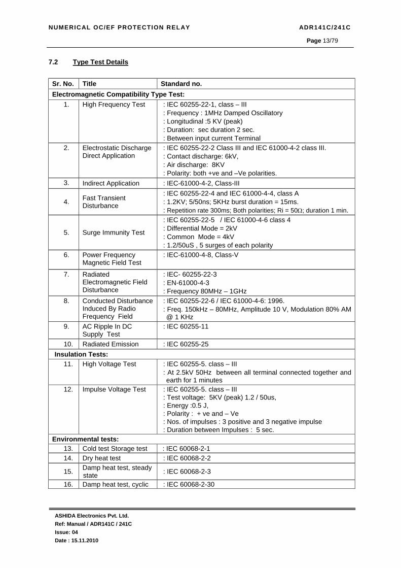
7.2 Type Test Details
Sr. No. Title Standard no. Electromagnetic Compatibility Type Test:
1. High Frequency Test : IEC 60255-22-1, class – III : Frequency : 1MHz Damped Oscillatory : Longitudinal :5 KV (peak) : Duration: sec duration 2 sec. : Between input current Terminal
2. Electrostatic Discharge Direct Application
: IEC 60255-22-2 Class III and IEC 61000-4-2 class III. : Contact discharge: 6kV, : Air discharge: 8KV : Polarity: both +ve and –Ve polarities.
3. Indirect Application : IEC-61000-4-2, Class-III
4. Fast Transient Disturbance
: IEC 60255-22-4 and IEC 61000-4-4, class A : 1.2KV; 5/50ns; 5KHz burst duration = 15ms. : Repetition rate 300ms; Both polarities; Ri = 50Ω; duration 1 min.
5. Surge Immunity Test
: IEC 60255-22-5 / IEC 61000-4-6 class 4 : Differential Mode = 2kV : Common Mode = 4kV : 1.2/50uS , 5 surges of each polarity
6. Power Frequency Magnetic Field Test
: IEC-61000-4-8, Class-V
7. Radiated Electromagnetic Field Disturbance
: IEC- 60255-22-3 : EN-61000-4-3 : Frequency 80MHz – 1GHz
8. Conducted Disturbance Induced By Radio Frequency Field
: IEC 60255-22-6 / IEC 61000-4-6: 1996. : Freq. 150kHz – 80MHz, Amplitude 10 V, Modulation 80% AM @ 1 KHz
9. AC Ripple In DC Supply Test
: IEC 60255-11
10. Radiated Emission : IEC 60255-25 Insulation Tests:
11. High Voltage Test
: IEC 60255-5. class – III : At 2.5kV 50Hz between all terminal connected together and earth for 1 minutes
12. Impulse Voltage Test
: IEC 60255-5. class – III : Test voltage: 5KV (peak) 1.2 / 50us, : Energy :0.5 J, : Polarity : + ve and – Ve : Nos. of impulses : 3 positive and 3 negative impulse : Duration between Impulses : 5 sec.
Environmental tests: 13. Cold test Storage test : IEC 60068-2-1 14. Dry heat test : IEC 60068-2-2
15. Damp heat test, steady state : IEC 60068-2-3
16. Damp heat test, cyclic : IEC 60068-2-30

NUMERICAL OC/EF PROTECTION RELAY ADR141C/241C
ASHIDA Electronics Pvt. Ltd. Ref: Manual / ADR141C / 241C Issue: 04 Date : 15.11.2010
Page 14/79
Mechanical tests
17. Vibration
: IEC 60255-21-1 class 1 : Frequency Range = 10Hz – 150Hz, acceleration. = 1gn (9.8 m/s2)
: Sweep rate 1 octave/min; 20 cycle in 3 orthogonal axis. 18. Bump Test : IEC 60255-21-2 Class-1
: 1000 bumps of 10gn peak acceleration and 16ms pulse duration in each of the two opposite direction per axis as per IEC 60255-21-2 class 1 No. of axes . 3.
19. Shock Withstand : IEC 60255-21-2 Clas-1 : 3 shocks of 15gn peak acceleration and 11ms pulse in each of two opposite direction . No. of axis : 3
20. Seismic Test : IEC 60255-21-3 : In single axis sine sweep in X-axis sweep (@a sweep rate of 1 octave/minute) vibration in the frequency range (5-40 Hz) at amplitude of 3.5mm or 1.0gn (whichever is less)
: In single axis sine sweep in Y-axis - sweep (@a sweep rate of 1 octave/minute) vibration in the frequency range (5-40 Hz) at amplitude of 1.5mm or 0.5gn (whichever is less)


NUMERICAL OC/EF PROTECTION RELAY ADR141C/241C
ASHIDA Electronics Pvt. Ltd. Ref: Manual / ADR141C / 241C Issue: 04 Date : 15.11.2010
Page 17/79
8.0 Front Panel and Control
6 7 5 8
1
2
3
4
66 77 55 88
11
22
33
44
6 7 5 8
1
2
3
4
66 77 55 88
11
22
33
44
Fig. 4.1
Sr. No. Legend Description LEDs
Total 4 bi-colors LED (Red and Green) are provided for user interface. Some of LEDs are pre defined others are spare and can be programmed as per the requirement. Following are pre defined LEDs
1 L1 ON : Green LED indicates Relay OK (Protection Healthy) : Red LED indicates Fault in following conditions.
1. Problem in relay Hardware. 2. Trip Circuit Fault
2 L2 PKP : Red LED indicate Start of timer Self Reset (SR) Type
3 L3 FAULT : Red LED indicate Relay Operated Flag (HR)
4 L4 TRIP : Green LED indicates Output TRIP relay contact closer (SR) Type
5 LCD display 16 character by 2 line back-lit LCD display will be provided for display of settings / status and measured value such as line current etc.
6 LED RESET/EDIT
1 Key provided for LED Reset / EDIT
7 HW Reset 1 key provided for Hardware reset. This key will be interlocked with LED Reset / EDIT.
8 Navigation Key
4 keys provided for navigation through different display menu and to do setting

NUMERICAL OC/EF PROTECTION RELAY ADR141C/241C
ASHIDA Electronics Pvt. Ltd. Ref: Manual / ADR141C / 241C Issue: 04 Date : 15.11.2010
Page 18/79
8.1 USER INTERFACE 8.1.1 LCD Display
Back-lit LCD display 16 character by 2 line is provided for parameter and setting display and
for easy viewing of measurement, setting, fault records, date & time, error message. Back-lit
will automatically switch off if any push button key will not be pressed for more than 100sec.
The display back-lit can be made ON by pressing any push button key. Back-lit is also
automatically turned ON when any tripping occurs on particular equipment.
8.1.2 Touch Keys
The function of relay is controlled by the following keys, Left Arrow key ( ), Right Arrow key
( ), Up Arrow key (+ / ), Down Arrow key (- / ) and LED Reset Key and HW Reset Key
which are provided on the Front Plate.
• When the Right Arrow key ( ) is pressed the operator is able to view the setting of the
relay. When the Right Arrow key ( ) is pressed again it will go to the next setting page,
but in case there are no more setting to be displayed it returns to the main menu.
• When the Left Arrow key ( ) is pressed than you are able to enter the setting which can
be now modified in the Main Menu using Up Arrow key (+ / ) Down Arrow key (- / ).
When the Left Arrow key ( ) pressed again it will go to the next setting.
• The Up Arrow key (+ / ) is used for two purposes: 1) ( ) To scroll the Main Menu and
2) (+) To increment the value in the setting mode.
• The Down Arrow key (- / ) is used for two purposes: 1) ( ) To scroll the Main Menu and
2) (-) To decrement the value in the setting mode.
• The Left Arrow key ( ) Right Arrow key ( ) can be used to go forward or backward,
both when doing the settings and while viewing the settings
‘LED RESET/EDIT’ key
• ‘LED RESET/EDIT’ key is used to Reset the Trip Flags.
• ‘LED RESET/EDIT’ key is used to display the Curser while setting the Password and the
Relay Led Configuration.
• LED RESET/EDIT’ key is used to discard while doing the settings and abort to Main
Menu.
Note: At the time of setting if changes are not carried within 100s then the display will reset
itself and return to the main menu.
‘HW RESET’ key ‘HW RESET’ key is never require in normal operation, It is in series with ‘LED RESET/EDIT’
key, When both keys are pressed simultaneously it reset total hardware of relay. This
normally is required during firmware update of relay.

NUMERICAL OC/EF PROTECTION RELAY ADR141C/241C
ASHIDA Electronics Pvt. Ltd. Ref: Manual / ADR141C / 241C Issue: 04 Date : 15.11.2010
Page 19/79
8.1.3 LED’s
The relay is having total 4 nos of dual colour LED of high intensity for easy identification of
type of fault for easy user interface.
Sr. No. Legend Description
1 L1 ON : Green LED indicates Relay OK (Protection Healthy) : Red LED indicates Fault in following conditions. 1. Problem in relay Hardware. 2. Trip Circuit Fault
2 L2 PKP : Red LED indicate Start of timer Self Reset (SR) Type
3 L3 FAULT : Red LED indicate Relay Operated Flag (HR)
4 L4 TRIP : Green LED indicates Output TRIP relay contact closer (SR) Type
8.2 Password
8.2.1 Password Entry and changing the password To enter password in all ADR141C refer following steps (User can go to this screen by
pressing HW RESET + LED RESET/EDIT Simultaneously
Password = 0001 Use Inr/Dec ⌃
To Enter the previously set Password Press the LED Reset Key this will display the curser (⌃ )below the password digits at Extreme Right ( 0000 ) thiscurser ( ⌃ ) can be shifted right to left and left to right usingthe left arrow key ( ) and Right Arrow key ( ). By using the up arrow key ( + / ) or the down arrow key ( - /
) a given value can be set for each of the digits. The rangeis from 0 to F. (The range is from 0000 – FFFF)
General Settings
Password protected window for “General Setting’’ for setting New Password, Unit ID, CT sec. CT primary, Test Block, Trip Ckt and Baud Rate, Press the left arrow key ( ) the relay will display as follow.
R= 0000 Y = 0000 B = 0000A
This is default window showing the actual Primary Load Current as per “CT Sec” selection Press the left arrow key ( ) the relay will display as follows.
Pri. Current
This window is showing Main menu. Press the down arrow key (- / ) the relay will display as follows.

NUMERICAL OC/EF PROTECTION RELAY ADR141C/241C
ASHIDA Electronics Pvt. Ltd. Ref: Manual / ADR141C / 241C Issue: 04 Date : 15.11.2010
Page 20/79
Mode for Save? Save Settings
Now again press the left arrow key ( ) the ÓK’ window will appear for a moment and the control will automatically return to ‘’General Settings’
→ General Settings ←
OK This window will flash for moment The control will return to the main menu
- - -
Password = 0000 New Password ⌃
To Change Password (New Password) Press the LED Reset Key this will display the curser ( ⌃ )below the password digits at Extreme Right ( 0000 ) thiscurser ( ⌃ ) can be shifted right to left and left to right usingthe left arrow key ( ) and Right Arrow key ( ). By using the up arrow key ( + / ) or the down arrow key ( - /
) a given value can be set for each of the digits. The rangeis from 0 to F. (The range is from 0000 – FFFF) When the desired Password is set press the LED Reset/EDITKey it will come out of curser ( ⌃ ). Press the left arrow key ( ) the relay will display other windows one by one till the following window.
When the Password is set, press the LED Reset Key it willcome out of curser ( ⌃ ). Press the left arrow key ( ) the relay will display as follow. Note: • Default password setting is ‘0000’ • The set Password will remain common for all the
settings

NUMERICAL OC/EF PROTECTION RELAY ADR141C/241C
ASHIDA Electronics Pvt. Ltd. Ref: Manual / ADR141C / 241C Issue: 04 Date : 15.11.2010
Page 21/79
8.2.2 Clear Password There are unlinking event when user forgets the password, in such case password can be
cleared by pressing following sequences.
1) Press ‘HW RESET’ + ‘LED RESET/EDIT’, this will initialize relay hardware and the
following message is displayed.
2) Press left arrow key ( ) as soon as the above message is displayed and hold this key till
the following message is display, this will Reset password to Zero
Ashida Digital OC/EF Relay
Fault Memories & Password clear
R= 0000 Y = 0000 B = 0000A
ADR141C – 01.15 Unit ID = 0001

NUMERICAL OC/EF PROTECTION RELAY ADR141C/241C
ASHIDA Electronics Pvt. Ltd. Ref: Manual / ADR141C / 241C Issue: 04 Date : 15.11.2010
Page 22/79
8.3 MENUS
8.3.1 Default Display After Power ON or when the HW RESET and LED RESET/EDIT push button is pressed simultaneously, the relay will display the following message.
8.3.2 Main Menu List
Ashida Digital OC/EF Relay
This window will flash momentarily showing the following Relay Name: OC/EF Relay Then the control will go automatically to next window.
R = 0000 Y = 0000 B = 0000A
This is default window showing the actual Primary Load Current as per “CT Pri” selection.
Primary current General Settings Relay setting Cold Load Relay/LED Config Trip Test Fault 1 Fault 2 Fault 3 Fault 4 Fault 5 Error Log Status Date/Time Secondary Current
Primary Current, General Settings, Relay setting, Cold Load, Relay/LED Config, Trip Test, Fault 1, Fault 2, Fault 3, Fault 4, Fault 5, Error Log, Status, Date/Time, and Secondary Current these are the Main Menus available in this relay. Since the LCD Display consist only of 2 Lines, the main menu list can be scrolled up or down by using the up arrow key (+ / ) or the down arrow key ( - / ).
R = 0000 Y = 0000 B = 0000A
This is default window showing the actual Primary Load Current as per “CT Primary” selection Press the left arrow key ( ) the relay will display Main menudirectly as follows.
ADR141C - Ver. 01.15 Unit ID : 0001
This window will flash momentarily showing the following Relay Type : ADR141C Software Version : V01.15 Unit ID = 0001 Then the control will go automatically to default window

NUMERICAL OC/EF PROTECTION RELAY ADR141C/241C
ASHIDA Electronics Pvt. Ltd. Ref: Manual / ADR141C / 241C Issue: 04 Date : 15.11.2010
Page 23/79
8.3.2.1 Main Menu List Details
Pri. Current
This menu is to view the actual load current in Primary as per the CT Primary selection. Press the down arrow key (- / ) the relay will display as follow.
General Settings
Password protected window for “General Setting’’ for setting New Password, Unit ID, CT Secondary, CT Primary Test Block, Trip Ckt. BF Enable, BF Delay & Baud Rate. Press the down arrow key (- / ) the relay will display as follow.
Relay Settings
Password protected window for “Relay Settings’’ for setting IP> Enable, IP> Range, IP TMS, IP>> Enable, IP>> Multiply by 50, 3Io> Enable, 3Io> Range, 3Io TMS, 3Io>> Enable, 3Io>> Multiply by 50, IP Curve, 3Io Curve, IP>> Delay, 3Io>> Delay, IP>C6 Delay & 3Io>C6 Delay. Press the down arrow key (- / ) the relay will display as follow.
Relay/LED Config
Password protected window for “Relay/LED Config.” for Setting Password, Load fact Set, RL1 A, RL1 B, RL2 A, RL2 B, RL3 A, RL3 B, RL4 A, RL4 B, L1 Green A, L1 Green B, L1 Red A, L1 Red B, L2 Green A, L2 Green B, L2 Red A, L2 Red B, L3 Green A, L3 Green B, L3 Red A, L3 Red B, L4 Green A, L4 Green B, L4 Red A and L4 Red B. Press the down arrow key ( - / ) the relay will display as follow.
Fault 1
This menu is to view the latest Fault data stored by the relay.That is Instantaneous and Phase Current, Trip Counter (TC),Date & Time and primary current. Press the down arrow key (- / ) the relay will display as follow.
Trip Test
This function is used for Tripping purpose that is by pressing on Right Arrow key ( ). Press the down arrow key (- / ) the relay will display as follow.
Cold Load
Password protected window for “Cold Load” for setting CL Enable, CL Timer, IP> Enable, IP> Range, IP TMS, IP>> Enable, IP>> Multiply, 3Io> Enable, 3Io> Range, 3Io TMS, 3Io>> Enable, 3Io>> Multiply, IP Curve, 3Io Curve, IP>> Delay, 3Io>> Delay, IP> C6 Delay, 3Io> C6 Delay. Press the down arrow key ( - / ) the relay will display as follow.

NUMERICAL OC/EF PROTECTION RELAY ADR141C/241C
ASHIDA Electronics Pvt. Ltd. Ref: Manual / ADR141C / 241C Issue: 04 Date : 15.11.2010
Page 24/79
Status
This menu is to view the Status that is Digital Input, Trip Ckt., Ckt Breaker and S/W & H/W versions. Press the down arrow key (- / ) the relay will display as follow.
Error Log
This menu is to view the Error Code detected by the self supervision function of the relay. Press the down arrow key (- / ) the relay will display as follow.
Date/Time
Password protected window for setting “Date/Time’’ Press the down arrow key (- / ) the relay will display as follow.
Fault 2
This menu is to view the First latest Fault data stored by therelay. That is Instantaneous and Phase Current, Trip Counter(TC), Date & Time and primary current. Press the down arrow key (- / ) the relay will display as follow.
Fault 3
This menu is to view the second latest Fault data stored bythe relay. That is Instantaneous and Phase Current, TripCounter (TC), Date & Time and primary current. Press the down arrow key (- / ) the relay will display as follow.
Fault 4
This menu is to view the third latest Fault data stored by therelay. That is Instantaneous and Phase Current, Trip Counter(TC), Date & Time and primary current. Press the down arrow key (- / ) the relay will display as follow.
Fault 5
This menu is to view the fourth latest Fault data stored by therelay. That is Instantaneous and Phase Current, Trip Counter(TC), Date & Time and primary current. Press the down arrow key (- / ) the relay will display as follow.
Sec. Current
This menu is to view the actual load current in Secondary as per the CT Secondary selection. Press the down arrow key (- / ) the relay will display as follow.
NUMERICAL OC/EF PROTECTION RELAY ADR141C/241C
ASHIDA Electronics Pvt. Ltd. Ref: Manual / ADR141C / 241C Issue: 04 Date : 15.11.2010
Page 25/79
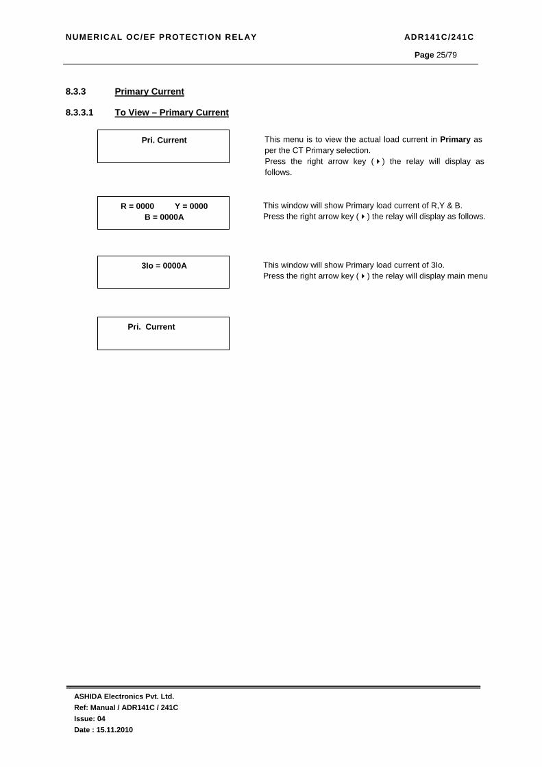
8.3.3 Primary Current 8.3.3.1 To View – Primary Current
Pri. Current
This menu is to view the actual load current in Primary as per the CT Primary selection. Press the right arrow key ( ) the relay will display as follows.
R = 0000 Y = 0000 B = 0000A
This window will show Primary load current of R,Y & B. Press the right arrow key ( ) the relay will display as follows.
Pri. Current
3Io = 0000A
This window will show Primary load current of 3Io. Press the right arrow key ( ) the relay will display main menu
NUMERICAL OC/EF PROTECTION RELAY ADR141C/241C
ASHIDA Electronics Pvt. Ltd. Ref: Manual / ADR141C / 241C Issue: 04 Date : 15.11.2010
Page 26/79
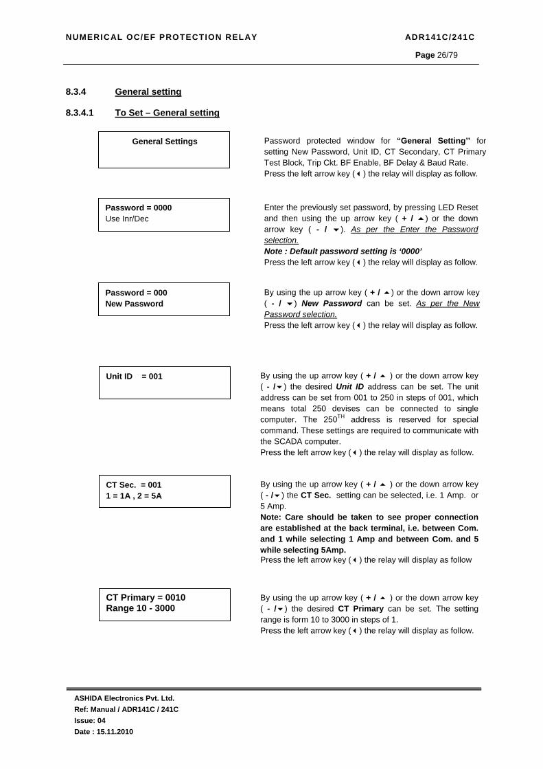
8.3.4 General setting
8.3.4.1 To Set – General setting
General Settings
Password protected window for “General Setting’’ for setting New Password, Unit ID, CT Secondary, CT Primary Test Block, Trip Ckt. BF Enable, BF Delay & Baud Rate. Press the left arrow key ( ) the relay will display as follow.
Unit ID = 001
By using the up arrow key ( + / ) or the down arrow key ( - / ) the desired Unit ID address can be set. The unit address can be set from 001 to 250 in steps of 001, which means total 250 devises can be connected to single computer. The 250TH address is reserved for special command. These settings are required to communicate with the SCADA computer. Press the left arrow key ( ) the relay will display as follow.
CT Sec. = 001 1 = 1A , 2 = 5A
By using the up arrow key ( + / ) or the down arrow key ( - / ) the CT Sec. setting can be selected, i.e. 1 Amp. or 5 Amp. Note: Care should be taken to see proper connection are established at the back terminal, i.e. between Com. and 1 while selecting 1 Amp and between Com. and 5 while selecting 5Amp. Press the left arrow key ( ) the relay will display as follow
CT Primary = 0010 Range 10 - 3000
By using the up arrow key ( + / ) or the down arrow key ( - / ) the desired CT Primary can be set. The setting range is form 10 to 3000 in steps of 1. Press the left arrow key ( ) the relay will display as follow.
Password = 000 New Password
By using the up arrow key ( + / ) or the down arrow key ( - / ) New Password can be set. As per the New Password selection. Press the left arrow key ( ) the relay will display as follow.
Password = 0000 Use Inr/Dec
Enter the previously set password, by pressing LED Reset and then using the up arrow key ( + / ) or the down arrow key ( - / ). As per the Enter the Password selection. Note : Default password setting is ‘0000’ Press the left arrow key ( ) the relay will display as follow.

NUMERICAL OC/EF PROTECTION RELAY ADR141C/241C
ASHIDA Electronics Pvt. Ltd. Ref: Manual / ADR141C / 241C Issue: 04 Date : 15.11.2010
Page 27/79
Test Block = 002 01: Yes 02: N0
This setting is use to block Trip Test button function. Normally Trip Test is required during pre commission testing to check operation of relay and panel wiring. By using the up arrow key ( + / ) or the down arrow key - / ) the desired Test block can be enable or disable, i.e. 1 or 2. When the given set value is 1 then it will enable Trip Test Key but when the given set value is 2 then Trip Test key will be blocked. The setting range is form 1 to 2 in steps of 1. Press the left arrow key ( ) the relay will display as follow.
General Setting
Trip Ckt. = 002 01: Yes, 02: No
By using the up arrow key ( + / ) or the down arrow key ( - / ) the Trip Ckt can be selected, i.e. 1 or 2. 1 is for YES and 2 is for NO. If set YES then Trip Ckt Supervision is enabled and if set NO then it will be disabled Press the left arrow key ( ) the relay will display as follow.
BF Enable = 002 01: Yes, 02: No
By using the up arrow key ( + / ) or the down arrow key ( - / ) the desired BF Enable can be selected. i.e. 1 or 2. 1 is for YES and 2 is for NO. If set YES then BF Enable is enabled and if set NO then it will be disabled Press the left arrow key ( ) the relay will display as follow.
Save Setting? Mode For Save
To Save any changes. Press the left arrow key ( ) the relay will save the changes and the following message is display. Note: If changes made are not to be saved press LED Reset or leave key pad untouched for 100 sec.
OK
This window will flash for moment The control will return to the main menu
BF Delay = 200 Range 50 – 800 ms
By using the up arrow key ( + / ) or the down arrow key ( - / ) the desired BF Delay can be selected. The setting range is from 50 to 800ms in step of 50ms. Press the left arrow key ( ) the relay will display as follow.

NUMERICAL OC/EF PROTECTION RELAY ADR141C/241C
ASHIDA Electronics Pvt. Ltd. Ref: Manual / ADR141C / 241C Issue: 04 Date : 15.11.2010
Page 28/79
8.3.4.2 To View – General Setting
General Setting
Press the right arrow key ( ) the relay will display as follows.
Test Block = NO Trip Ckt. = NO
This window will show General Setting done previously. Press the right arrow key ( ) the relay will display as follows.
Unit ID = 001 This window will show General Setting done previously. Press the right arrow key ( ) the relay will display as follows.
CT Sec. = 1Amp CT Primary = 0100A
This window will show General Setting done previously. Press the right arrow key ( ) the relay will display as follows.
General Setting
BF Enable = No BF Delay = 200
This window will show General Setting done previously. Press the right arrow key ( ) the relay will display as follows.
Baud Rate = 57600
This window will show General Setting done previously. Press the right arrow key ( ) the relay will display Main Menu.
NUMERICAL OC/EF PROTECTION RELAY ADR141C/241C
ASHIDA Electronics Pvt. Ltd. Ref: Manual / ADR141C / 241C Issue: 04 Date : 15.11.2010
Page 29/79
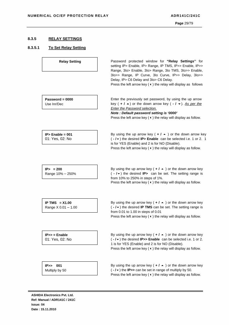
8.3.5 RELAY SETTINGS
8.3.5.1 To Set Relay Setting
Relay Setting
Password protected window for “Relay Settings’’ for setting IP> Enable, IP> Range, IP TMS, IP>> Enable, IP>> Range, 3Io> Enable, 3Io> Range, 3Io TMS, 3Io>> Enable, 3Io>> Range, IP Curve, 3Io Curve, IP>> Delay, 3Io>> Delay, IP> C6 Delay and 3Io> C6 Delay. Press the left arrow key ( ) the relay will display as follows
Password = 0000 Use Inr/Dec
Enter the previously set password, by using the up arrow key ( + / ) or the down arrow key ( - / ). As per the Enter the Password selection. Note : Default password setting is ‘0000’ Press the left arrow key ( ) the relay will display as follow.
IP> Enable = 001 01: Yes, 02: No
By using the up arrow key ( + / ) or the down arrow key ( - / ) the desired IP> Enable can be selected i.e. 1 or 2. 1 is for YES (Enable) and 2 is for NO (Disable). Press the left arrow key ( ) the relay will display as follow.
IP> = 200 Range 10% – 250%
By using the up arrow key ( + / ) or the down arrow key ( - / ) the desired IP> can be set. The setting range is from 10% to 250% in steps of 1%. Press the left arrow key ( ) the relay will display as follow.
IP TMS = X1.00 Range X 0.01 – 1.00
By using the up arrow key ( + / ) or the down arrow key ( - / ) the desired IP TMS can be set. The setting range is from 0.01 to 1.00 in steps of 0.01 Press the left arrow key ( ) the relay will display as follow.
IP>> = Enable 01: Yes, 02: No
By using the up arrow key ( + / ) or the down arrow key ( - / ) the desired IP>> Enable can be selected i.e. 1 or 2. 1 is for YES (Enable) and 2 is for NO (Disable). Press the left arrow key ( ) the relay will display as follow.
IP>> 001 Multiply by 50
By using the up arrow key ( + / ) or the down arrow key ( - / ) the IP>> can be set in range of multiply by 50. Press the left arrow key ( ) the relay will display as follow.

NUMERICAL OC/EF PROTECTION RELAY ADR141C/241C
ASHIDA Electronics Pvt. Ltd. Ref: Manual / ADR141C / 241C Issue: 04 Date : 15.11.2010
Page 30/79
3Io> Enable = 002 01: Yes, 02: No
By using the up arrow key ( + / ) or the down arrow key ( - / ) the desired 3Io> Enable can be selected i.e. 1 or 2. 1 is for YES (Enable) and 2 is for NO (Disable). Press the left arrow key ( ) the relay will display as follow.
3Io>> = 001 Multiply by 50
By using the up arrow key ( + / ) or the down arrow key ( - / ) the desired 3Io>> can be set. The setting range is Multiply of 50 in steps of 1. Press the left arrow key ( ) the relay will display as follow.
3Io TMS = X1.00 Range X0.01 – 1.00
By using the up arrow key ( + / ) or the down arrow key ( - / ) the desired 3Io TMS can be set. The setting range is from X0.01 – 1.00 in steps of 0.01. Press the left arrow key ( ) the relay will display as follow.
Ip Curve = 006 Range C1 – C6
By using the up arrow key ( + / ) or the down arrow key ( - / ) the desired Ip Curve can be selected. Six different types of curves are provided from C1 to C6. When the given value is 001, curve 1 is selected and when the given value 002, curve 2 is selected. In similar manner any desired curve can be selected as 001 to 006 correspond respectively with C1 to C6. Press the left arrow key ( ) the relay will display as follow.
3Io Curve = 006 Range C1 – C6
By using the up arrow key ( + / ) or the down arrow key ( - / ) the desired 3Io Curve can be selected. Six different types of curves are provided from C1 to C6. When the given value is 001, curve 1 is selected and when the given value 002, curve 2 is selected. Press the left arrow key ( ) the relay will display as follow
3Io> = 200 Range 10 – 250%
By using the up arrow key ( + / ) or the down arrow key ( - / ) the desired 3Io> can be set. The setting range is from 10% to 250% in steps of 1%. Press the left arrow key ( ) the relay will display as follow.
3Io>> Enable = 002 01: Yes, 02: No
By using the up arrow key ( + / ) or the down arrow key ( - / ) the desired 3Io>> Enable can be selected i.e. 1 or 2. 1 is for YES (Enable) and 2 is for NO (Disable). Press the left arrow key ( ) the relay will display as follow.

NUMERICAL OC/EF PROTECTION RELAY ADR141C/241C
ASHIDA Electronics Pvt. Ltd. Ref: Manual / ADR141C / 241C Issue: 04 Date : 15.11.2010
Page 31/79
Ip>> Delay = 2.00 Range 0 – 2.00s
By using the up arrow key ( + / ) or the down arrow key ( - / ) the desired Ip>> Delay can be selected. The setting range is from 0 to 2.00s in steps of 0.01s. Press the left arrow key ( ) the relay will display as follow.
3Io>> Delay = 2.00 Range 0 – 2.00s
By using the up arrow key ( + / ) or the down arrow key ( - / ) the desired 3Io>> Delay can be selected. The setting range is from 0 to 2.00s in steps of 0.01s. Press the left arrow key ( ) the relay will display as follow.
Ip> C6 Delay = 99.5 Range 0.1 – 99.9s
By using the up arrow key ( + / ) or the down arrow key ( - / ) the desired Ip>C6 Delay can be selected. Range is in between 0.1 – 99.9s in steps of 00.1s Press the left arrow key ( ) the relay will display as follow
3Io> C6 Delay = 99.5 Range 0.1 – 99.9s
By using the up arrow key ( + / ) or the down arrow key ( - / ) the desired 3Io>C6 Delay can be selected. Range is in between 0.1 – 99.9s in steps of 00.1s Press the left arrow key ( ) the relay will display as follow
Save Settings? Mode for Save
To Save any changes, Press the left arrow key ( ) the relay will save the change and the following message is display. Note: If changes made are not to be saved press LED Reset or leave key pad untouched for 100Sec.
OK
This window will flash for moment The control will return to the main menu
Relay Setting

NUMERICAL OC/EF PROTECTION RELAY ADR141C/241C
ASHIDA Electronics Pvt. Ltd. Ref: Manual / ADR141C / 241C Issue: 04 Date : 15.11.2010
Page 32/79
8.3.5.2 To View – Relay Setting
Relay Setting
Press the right arrow key ( ) the relay will display as follow.
Ip> Enable = Yes Ip>> Enable = Yes
This window will show Relay setting done previously. Press the right arrow key ( ) the relay will display as follow.
3Io> Enable = No 3Io>> Enable = No
This window will show Relay setting done previously. Press the right arrow key ( ) the relay will display as follow.
IP> Normal Inv. 2 3Io> Normal Inv. 1
This window will show Relay setting done previously. Press the right arrow key ( ) the relay will display as follow.
Relay Setting
IP>200% t= X1.00 IP>>800%
This window will show Relay setting done previously. Press the right arrow key ( ) the relay will display as follow.
3Io>020% t= X1.00 3Io>>200
This window will show Relay setting done previously. Press the right arrow key ( ) the relay will display as follow.
IP>> Delay = 0.00 3Io>> Delay = 0.00
This window will show Relay setting done previously. Press the right arrow key ( ) the relay will display as follow.
IP> C6 Delay = 04.0 3Io> C6 Delay = 00.0
This window will show Relay setting done previously. Press the right arrow key ( ) the relay will display the main menu.
NUMERICAL OC/EF PROTECTION RELAY ADR141C/241C
ASHIDA Electronics Pvt. Ltd. Ref: Manual / ADR141C / 241C Issue: 04 Date : 15.11.2010
Page 33/79
8.3.6 COLD LOAD SETTINGS
8.3.6.1 To Set Cold Load Setting
Cold Load Setting
Password protected window for “Cold Load” for setting CL Enable, CL Timer, IP> Enable, IP> Range, IP TMS, IP>> Enable, IP>> Multiply, 3Io> Enable, 3Io> Range, 3Io TMS, 3Io>> Enable, 3Io>> Multiply, IP Curve, 3Io Curve, IP>> Delay, 3Io>> Delay, IP> C6 Delay, 3Io> C6 Delay. Press the left arrow key ( ) the relay will display as follows.
Password = 0000 Use Inr/Dec
Enter the previously set password, by pressing LED RESET key and using the up arrow key ( + / ) or the down arrow key ( - / ). As per the Enter the Password selection. Note: Default password setting is ‘0000’ Press the left arrow key ( ) the relay will display as follow.
CL Enable = 001 01: Yes, 02: No
By using the up arrow key ( + / ) or the down arrow key ( - / ) the desired CL Enable can be selected i.e. 1 or 2. 1 is for YES (Enable) and 2 is for NO (Disable). Press the left arrow key ( ) the relay will display as follows.
CL Timer = 0.50 Range 0 – 2.00S
By using the up arrow key ( + / ) or the down arrow key ( - / ) the desired CL Timer can be set. The setting range is from 0 – 2.00S in steps of 0.01. Press the left arrow key ( ) the relay will display as follow.
IP> Enable = 001 01: Yes, 02: No
By using the up arrow key ( + / ) or the down arrow key ( - / ) the desired IP> Enable can be selected i.e. 1 or 2. 1 is for YES (Enable) and 2 is for NO (Disable). Press the left arrow key ( ) the relay will display as follow.
IP> = 250 Range 10 – 250%
By using the up arrow key ( + / ) or the down arrow key ( - / ) the IP> can be set in Range 10 – 250% in steps of 001% Press the left arrow key ( ) the relay will display as follow.
IP TMS = X1.00 Range X0.01 – 1.0
By using the up arrow key ( + / ) or the down arrow key ( - / ) the IP TMS can be set in range of X0.01 – 1.0 in step of 0.01 Press the left arrow key ( ) the relay will display as follow.

NUMERICAL OC/EF PROTECTION RELAY ADR141C/241C
ASHIDA Electronics Pvt. Ltd. Ref: Manual / ADR141C / 241C Issue: 04 Date : 15.11.2010
Page 34/79
Ip>> Enable = 002 01: Yes, 02: No
By using the up arrow key ( + / ) or the down arrow key ( - / ) the desired IP>> Enable can be selected i.e. 1 or 2. 1 is for YES (Enable) and 2 is for NO (Disable). Press the left arrow key ( ) the relay will display as follow.
3Io>> = 001 Multiply by 50
By using the up arrow key (+ / ) or the down arrow key ( - / ) the desired 3Io>> can be set. The setting range is multiply of 50 in steps of 1. Press the left arrow key ( ) the relay will display as follow.
3Io TMS = X1.00 Range X0.01 – 1.00
By using the up arrow key ( + / ) or the down arrow key ( - / ) the desired 3Io TMS can be set. The setting range is from X0.01 – 1.00 in steps of 0.01. Press the left arrow key ( ) the relay will display as follow.
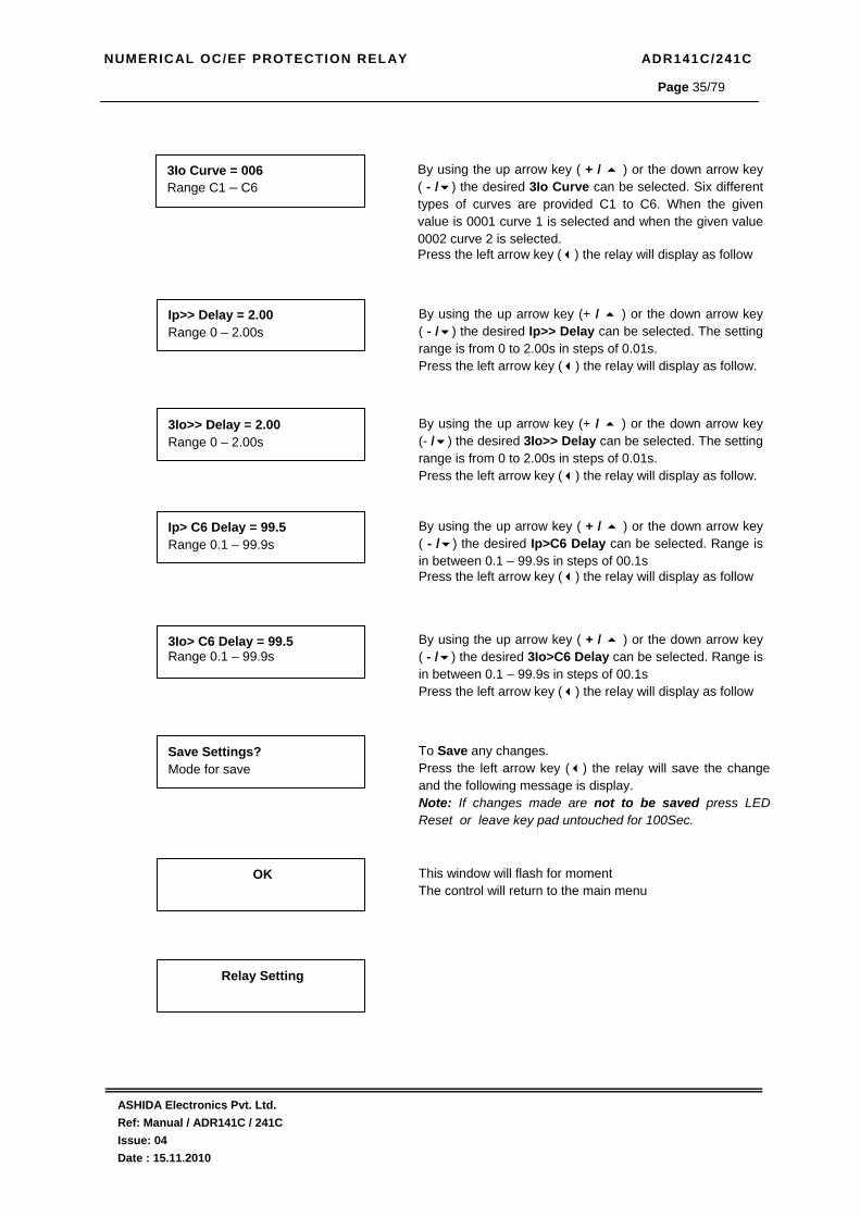
Ip Curve = 006 Range C1 – C6
By using the up arrow key (+ / ) or the down arrow key (- / ) the desired Ip Curve can be selected. Six different types of curves are provided C1 to C6. When the given value is 0001 curve 1 is selected and when the given value 0002 curve 2 is selected. In similar manner any desired curve can be selected as 0001 to 0006 correspond respectively with C1 to C6. Press the left arrow key ( ) the relay will display as follow.
Ip>> = 001 Multiply by 50
By using the up arrow key ( + / ) or the down arrow key ( - / ) the desired Ip>> can be set. The setting range is multiply of 50 in steps of 1. Press the left arrow key ( ) the relay will display as follow.
3Io>> Enable = 002 01: Yes, 02: No
By using the up arrow key ( + / ) or the down arrow key ( - / ) the desired 3Io>> Enable can be selected i.e. 1 or 2. 1 is for YES (Enable) and 2 is for NO (Disable). Press the left arrow key ( ) the relay will display as follow.
3Io> Enable = 002 01: Yes, 02: No
By using the up arrow key ( + / ) or the down arrow key ( - / ) the desired 3Io> Enable can be selected i.e. 1 or 2. 1 is for YES (Enable) and 2 is for NO (Disable). Press the left arrow key ( ) the relay will display as follow.
3Io> = 250 Range 10 – 250%
By using the up arrow key ( + / ) or the down arrow key ( - / ) the 3Io> can be set in Range 10 – 250% in steps of 001% Press the left arrow key ( ) the relay will display as follow.
NUMERICAL OC/EF PROTECTION RELAY ADR141C/241C
ASHIDA Electronics Pvt. Ltd. Ref: Manual / ADR141C / 241C Issue: 04 Date : 15.11.2010
Page 35/79
Ip>> Delay = 2.00 Range 0 – 2.00s
By using the up arrow key (+ / ) or the down arrow key ( - / ) the desired Ip>> Delay can be selected. The setting range is from 0 to 2.00s in steps of 0.01s. Press the left arrow key ( ) the relay will display as follow.
3Io>> Delay = 2.00 Range 0 – 2.00s
By using the up arrow key (+ / ) or the down arrow key (- / ) the desired 3Io>> Delay can be selected. The setting range is from 0 to 2.00s in steps of 0.01s. Press the left arrow key ( ) the relay will display as follow.
Ip> C6 Delay = 99.5 Range 0.1 – 99.9s
By using the up arrow key ( + / ) or the down arrow key ( - / ) the desired Ip>C6 Delay can be selected. Range is in between 0.1 – 99.9s in steps of 00.1s Press the left arrow key ( ) the relay will display as follow
3Io> C6 Delay = 99.5 Range 0.1 – 99.9s
By using the up arrow key ( + / ) or the down arrow key ( - / ) the desired 3Io>C6 Delay can be selected. Range is in between 0.1 – 99.9s in steps of 00.1s Press the left arrow key ( ) the relay will display as follow
Save Settings? Mode for save
To Save any changes. Press the left arrow key ( ) the relay will save the change and the following message is display. Note: If changes made are not to be saved press LED Reset or leave key pad untouched for 100Sec.
OK
This window will flash for moment The control will return to the main menu
Relay Setting
3Io Curve = 006 Range C1 – C6
By using the up arrow key ( + / ) or the down arrow key ( - / ) the desired 3Io Curve can be selected. Six different types of curves are provided C1 to C6. When the given value is 0001 curve 1 is selected and when the given value 0002 curve 2 is selected. Press the left arrow key ( ) the relay will display as follow

NUMERICAL OC/EF PROTECTION RELAY ADR141C/241C
ASHIDA Electronics Pvt. Ltd. Ref: Manual / ADR141C / 241C Issue: 04 Date : 15.11.2010
Page 36/79
8.3.6.2 To View – COLD LOAD Setting
Cold Load Setting
Press the right arrow key ( ) the relay will display as follow.
CL Enable = Yes CL Timer = 0.50
This window will show Cold Load setting done previously. Press the right arrow key ( ) the relay will display as follow.
IP> 250% t = X1.00 IP>> 1000%
This window will show Cold Load setting done previously. Press the right arrow key ( ) the relay will display as follow.
3Io> 250% t = X1.00 3Io>> 3000%
This window will show Cold Load setting done previously. Press the right arrow key ( ) the relay will display as follow.
Cold Load
IP> Enable = No IP>> Enable = Yes
This window will show Cold Load setting done previously. Press the right arrow key ( ) the relay will display as follow.
3Io> Enable = NO 3Io>> Enable = NO
This window will show Cold Load setting done previously. Press the right arrow key ( ) the relay will display as follow.
IP> Normal Inv. 1 3Io> Normal Inv. 1
This window will show Cold Load setting done previously. Press the right arrow key ( ) the relay will display as follow.
IP>> Delay = 0.00 3Io>> Delay = 0.00
This window will show Cold Load setting done previously. Press the right arrow key ( ) the relay will display as follow.
IP> C6 Delay = 00.5 3Io> C6Delay = 01.0
This window will show Cold Load setting done previously. Press the right arrow key ( ) the relay will display the main menu.
NUMERICAL OC/EF PROTECTION RELAY ADR141C/241C
ASHIDA Electronics Pvt. Ltd. Ref: Manual / ADR141C / 241C Issue: 04 Date : 15.11.2010
Page 37/79
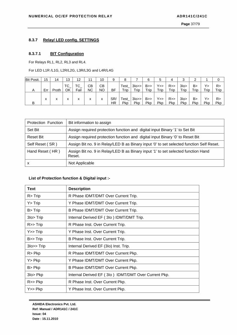
8.3.7 Relay/ LED config. SETTINGS 8.3.7.1 BIT Configuration For Relays RL1, RL2, RL3 and RL4. For LED L1R /L1G, L2R/L2G, L3R/L3G and L4R/L4G
Bit Posit. 15 14 13 12 11 10 9 8 7 6 5 4 3 2 1 0
A Err Proth TC_OK
TC_ Fail
CB NC
CB NO BF
Test_Trip
3Io>>Trip
B>> Trip
Y>> Trip
R>> Trip
3Io> Trip
B> Trip
Y> Trip
R> Trip
B x
x
x
x
x
x
SR/ HR
Test_Pkp
3Io>>Pkp
B>> Pkp
Y>> Pkp
R>> Pkp
3Io> Pkp
B> Pkp
Y> Pkp
R> Pkp
Protection Function Bit information to assign
Set Bit Assign required protection function and digital input Binary ‘1’ to Set Bit
Reset Bit Assign required protection function and digital input Binary ‘0’ to Reset Bit
Self Reset ( SR ) Assign Bit no. 9 in Relay/LED B as Binary input ‘0’ to set selected function Self Reset.
Hand Reset ( HR ) Assign Bit no. 9 in Relay/LED B as Binary input ‘1’ to set selected function Hand Reset.
x Not Applicable
List of Protection function & Digital input :-
Text Description
R> Trip R Phase IDMT/DMT Over Current Trip.
Y> Trip Y Phase IDMT/DMT Over Current Trip.
B> Trip B Phase IDMT/DMT Over Current Trip.
3Io> Trip Internal Derived EF ( 3Io ) IDMT/DMT Trip.
R>> Trip R Phase Inst. Over Current Trip.
Y>> Trip Y Phase Inst. Over Current Trip.
B>> Trip B Phase Inst. Over Current Trip.
3Io>> Trip Internal Derived EF (3Io) Inst. Trip.
R> Pkp R Phase IDMT/DMT Over Current Pkp.
Y> Pkp Y Phase IDMT/DMT Over Current Pkp.
B> Pkp B Phase IDMT/DMT Over Current Pkp.
3Io> Pkp Internal Derived EF ( 3Io ) IDMT/DMT Over Current Pkp.
R>> Pkp R Phase Inst. Over Current Pkp.
Y>> Pkp Y Phase Inst. Over Current Pkp.

NUMERICAL OC/EF PROTECTION RELAY ADR141C/241C
ASHIDA Electronics Pvt. Ltd. Ref: Manual / ADR141C / 241C Issue: 04 Date : 15.11.2010
Page 38/79
B>> Pkp B Phase Inst. Over Current Pkp.
3Io>> Pkp Internal Derived EF ( 3Io ) Inst. Over Current Pkp.
TestTrip Relay Trip from Test function
Test Pkp Relay Pkp from Test function
BF BF Relay Enable.
CB NC Trip Circuit Supervision Digital input
CB NO Trip Circuit Supervision Digital input
TC Fail Trip Circuit Supervision Faulty
TC OK Trip Circuit Supervision OK
Proth. Trip Circuit Supervision and Internal Hardware OK
Error Trip Circuit Supervision OR Internal Hardware Faulty
SR/HR Relays / LED can be set Self Reset (SR) / Hand Reset. Refer following table for some equivalent Binary, Hex and Decimal values.
Binary Value Hex decimal Values Decimal Values
0000 0 0
0001 1 1
0010 2 2
0011 3 3
0100 4 4
0101 5 5
0110 6 6
0111 7 7
1000 8 8
1001 9 9
1010 A 10
1011 B 11
1100 C 12
1101 D 13
1110 E 14
1111 F 15
NUMERICAL OC/EF PROTECTION RELAY ADR141C/241C
ASHIDA Electronics Pvt. Ltd. Ref: Manual / ADR141C / 241C Issue: 04 Date : 15.11.2010
Page 39/79
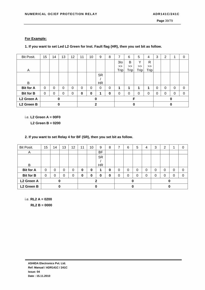
For Example: 1. If you want to set Led L2 Green for Inst. Fault flag (HR), then you set bit as follow.
i.e. L2 Green A = 00F0 L2 Green B = 0200 2. If you want to set Relay 4 for BF (SR), then you set bit as follow.
i.e. RL2 A = 0200 RL2 B = 0000
Bit Posit. 15 14 13 12 11 10 9 8 7 6 5 4 3 2 1 0
A
3Io>>Trip
B >>Trip
Y >>Trip
R >> Trip
B
SR/
HR Bit for A 0 0 0 0 0 0 0 0 1 1 1 1 0 0 0 0 Bit for B 0 0 0 0 0 0 1 0 0 0 0 0 0 0 0 0
L2 Green A 0 0 F 0 L2 Green B 0 2 0 0
Bit Posit. 15 14 13 12 11 10 9 8 7 6 5 4 3 2 1 0 A BF
B
SR/
HR Bit for A 0 0 0 0 0 0 1 0 0 0 0 0 0 0 0 0 Bit for B 0 0 0 0 0 0 0 0 0 0 0 0 0 0 0 0
L2 Green A 0 2 0 0 L2 Green B 0 0 0 0

NUMERICAL OC/EF PROTECTION RELAY ADR141C/241C
ASHIDA Electronics Pvt. Ltd. Ref: Manual / ADR141C / 241C Issue: 04 Date : 15.11.2010
Page 40/79
8.3.7.2 To Set –Relay/ LED config. Setting
Load Fact set =02 01: Yes 02: No
Load Fact Set if 01 i.e YES Then the factory defined setting will be loaded as follows: RL1 A = 01FF RL1 B = 0000 RL2 A = 01FF RL2 B = 0000 RL3 A = 0077 RL3 B = 0000 RL4 A = 0088 RL4 B = 0000 L1 Green A = 4000 L1 Green B = 0000 L1 Red A = 8000 L1 Red B = 0000 L2 Green A = 0000 L2 Green B = 0000 L2 Red A = 0000 L2 Red B = 01FF L3 Green A = 0000 L3 Green B = 0000 L3 Red A = 01FF L3 Red B = 0200 L4 Green A = 01FF L4 Green B = 0000 L4 Red A = 0000 L4 Red B = 0000 IF Load Factory setting is 02 i.e. NO then the Users can define the Setting as per his requirements. Press the LED Reset Key this will display the curser ( ⌃ )below the password digits at Extreme Right ( 0000 ) this curser( ⌃ ) can be shifted right to left and left to right using the leftarrow key ( ) and Right Arrow key ( ). By using the up arrow key ( + / ) or the down arrow key ( - /
) a given value can be set for each of the digits. The range isfrom 0 to F. (The range is from 0000 – FFFF)
Relay/LED’s config.
Password protected window for Relay/LED confi Setting Password, Load fact setting, RL1 A, RL1 B, RL2 A, RL2 B, RL3 A, RL3 B, RL4 A, RL4 B, L1 green A, L1 green B, L1 red A, L1 Red B, L2 green A, L2 green B, L2 Red A, L2 Red B, L3 green A, L3 green B, L3 red A, L3 red B, L4 green A, L4 green B, L4 Red A, L4 Red B. Press the left arrow key ( ) the relay will display as follow.
Password = 0001 Use Inr/Dec
Enter the previously set password, by using the up arrow key ( + / ) or the down arrow key ( - / ). As per the Enter the Password selection. Note: Default password setting is ’0000’ Press the left arrow key ( ) the relay will display as follow.

NUMERICAL OC/EF PROTECTION RELAY ADR141C/241C
ASHIDA Electronics Pvt. Ltd. Ref: Manual / ADR141C / 241C Issue: 04 Date : 15.11.2010
Page 41/79
RL2 A = 01FF
This window shows the Relay/LED configuration. That is RL2 A. Press the left arrow key ( ) the relay will display as follow.
RL2 B = 0000
This window shows the Relay/LED configuration. That is RL2 B Press the left arrow key ( ) the relay will display as follow.
RL3 A = 01FF
This window shows the Relay/LED configuration. That is RL3 A Press the left arrow key ( ) the relay will display as follow.
RL3 B = 0000
This window shows the Relay/LED configuration. That is RL3 B Press the left arrow key ( ) the relay will display as follow.
RL4 A = 01FF
This window shows the Relay/LED configuration. That is RL4 A Press the left arrow key ( ) the relay will display as follow.
RL4 B = 0000
This window shows the Relay/LED configuration. That is RL4 B. Press the left arrow key ( ) the relay will display as follow.
L1 Green A = 4000
This window shows the Relay/LED configuration. That is L1 green A. Press the left arrow key ( ) the relay will display as follow.
When the desired Password or bit is set press the LED ResetKey it will come out of curser ( ⌃ ). Note :The entire detailed information regarding the Bit specification is given below in Bit Definitions. Press the left arrow key ( ) the relay will display as follow.

NUMERICAL OC/EF PROTECTION RELAY ADR141C/241C
ASHIDA Electronics Pvt. Ltd. Ref: Manual / ADR141C / 241C Issue: 04 Date : 15.11.2010
Page 42/79
L1 Green B = 0000
This window shows the Relay/LED configuration. That is L1 green B. Press the left arrow key ( ) the relay will display as follow.
L1 Red A = 8000
This window shows the Relay/LED configuration. That is L1 Red A Press the left arrow key ( ) the relay will display as follow.
L1 Red B = 0000
This window shows the Relay/LED configuration. That is L1 Red B Press the left arrow key ( ) the relay will display as follow.
L2 green A = 0000
This window shows the Relay/LED configuration. That is L2 green A Press the left arrow key ( ) the relay will display as follow.
L2 green B = 0000
This window shows the Relay/LED configuration. That is L2 green B. Press the left arrow key ( ) the relay will display as follow.
L2 Red A = 0000
This window shows the Relay/LED configuration. That is L2 Red A. Press the left arrow key ( ) the relay will display as follow.
L2 Red B = 01FF
This window shows the Relay/LED configuration. That is L2 Red B. Press the left arrow key ( ) the relay will display as follow.
L3 green A = 0000
This window shows the Relay/LED configuration. That is L3 green A. Press the left arrow key ( ) the relay will display as follow.
L3 green B = 0000
This window shows the Relay/LED configuration. That is L3 green B. Press the left arrow key ( ) the relay will display as follow.

NUMERICAL OC/EF PROTECTION RELAY ADR141C/241C
ASHIDA Electronics Pvt. Ltd. Ref: Manual / ADR141C / 241C Issue: 04 Date : 15.11.2010
Page 43/79
Save Settings? Mode for Save
To Save any changes. Press the left arrow key ( ) the relay will save the change and the following message is display. Note: If changes made are not to be saved press LED Reset or leave key pad untouched for 100Sec.
OK
This window will flash for moment The control will return to the main menu
Relay/ LED Config. Setting
L3 Red A = 0000
This window shows the Relay/LED configuration. That is L3 Red A. Press the left arrow key ( ) the relay will display as follow.
L3 Red B = 0400
This window shows the Relay/LED configuration. That is L3 Red B. Press the left arrow key ( ) the relay will display as follow.
L4 Green A = 01FF
This window shows the Relay/LED configuration. That is L4 green A. Press the left arrow key ( ) the relay will display as follow.
L4 Green B = 0000
This window shows the Relay/LED configuration. That is L4 green B. Press the left arrow key ( ) the relay will display as follow.
L4 Red A = 0000
This window shows the Relay/LED configuration. That is L3 Red A. Press the left arrow key ( ) the relay will display as follow.
L4 Red B = 0400
This window shows the Relay/LED configuration. That is L3 Red B. Press the left arrow key ( ) the relay will display as follow.
NUMERICAL OC/EF PROTECTION RELAY ADR141C/241C
ASHIDA Electronics Pvt. Ltd. Ref: Manual / ADR141C / 241C Issue: 04 Date : 15.11.2010
Page 44/79
8.3.7.3 To View Relay/ LED Config. Setting
Relay/ LED Config. Setting
Press the right arrow key ( ) the relay will display as follow.
Loading Factory Settings : NO
This window will show Loading Factory Setting done previously. Press the right arrow key ( ) the relay will display as follow.
RL1 A = 01FF RL1 B = 0000
This window will show Relay config. setting done previously. Press the right arrow key ( ) the relay will display as follow.
L1 Green A = 0000 L1 Green B = 0000
This window will show Relay config. setting done previously. Press the right arrow key ( ) the relay will display as follow.
RL2 A = 01FF RL2 B = 0000
This window will show Relay config. setting done previously. Press the right arrow key ( ) the relay will display as follow.
RL3 A = 01FF RL3 B = 0000
This window will show Relay config. setting done previously. Press the right arrow key ( ) the relay will display as follow.
RL4 A = 0088 RL4 B = 0000
This window will show Relay config. setting done previously. Press the right arrow key ( ) the relay will display as follow.
L1 Red A = 8000 L1 Red B = 01FF
This window will show Relay config. setting done previously. Press the right arrow key ( ) the relay will display as follow.
NUMERICAL OC/EF PROTECTION RELAY ADR141C/241C
ASHIDA Electronics Pvt. Ltd. Ref: Manual / ADR141C / 241C Issue: 04 Date : 15.11.2010
Page 45/79
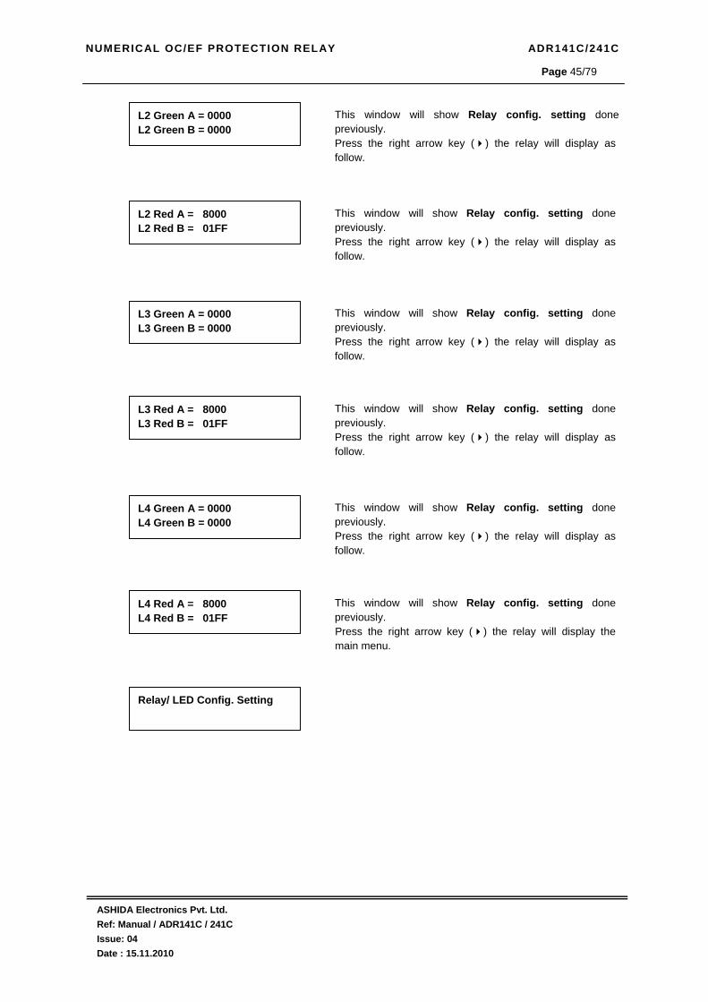
Relay/ LED Config. Setting
L2 Green A = 0000 L2 Green B = 0000
This window will show Relay config. setting done previously. Press the right arrow key ( ) the relay will display as follow.
L2 Red A = 8000 L2 Red B = 01FF
This window will show Relay config. setting done previously. Press the right arrow key ( ) the relay will display as follow.
L3 Green A = 0000 L3 Green B = 0000
This window will show Relay config. setting done previously. Press the right arrow key ( ) the relay will display as follow.
L3 Red A = 8000 L3 Red B = 01FF
This window will show Relay config. setting done previously. Press the right arrow key ( ) the relay will display as follow.
L4 Green A = 0000 L4 Green B = 0000
This window will show Relay config. setting done previously. Press the right arrow key ( ) the relay will display as follow.
L4 Red A = 8000 L4 Red B = 01FF
This window will show Relay config. setting done previously. Press the right arrow key ( ) the relay will display the main menu.
NUMERICAL OC/EF PROTECTION RELAY ADR141C/241C
ASHIDA Electronics Pvt. Ltd. Ref: Manual / ADR141C / 241C Issue: 04 Date : 15.11.2010
Page 46/79
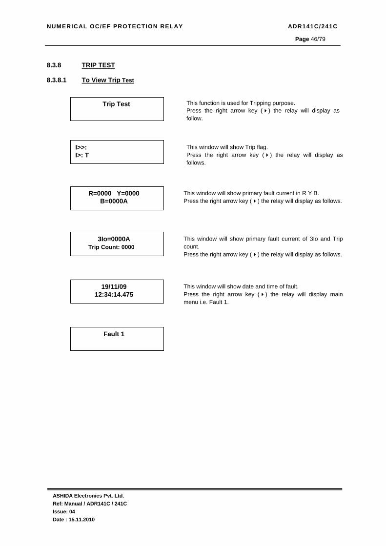
8.3.8 TRIP TEST
8.3.8.1 To View Trip Test
Trip Test This function is used for Tripping purpose. Press the right arrow key ( ) the relay will display as follow.
I>>: I>: T
This window will show Trip flag. Press the right arrow key ( ) the relay will display as follows.
R=0000 Y=0000 B=0000A
This window will show primary fault current in R Y B. Press the right arrow key ( ) the relay will display as follows.
3Io=0000A Trip Count: 0000
This window will show primary fault current of 3Io and Trip count. Press the right arrow key ( ) the relay will display as follows.
19/11/09 12:34:14.475
This window will show date and time of fault. Press the right arrow key ( ) the relay will display main menu i.e. Fault 1.
Fault 1
NUMERICAL OC/EF PROTECTION RELAY ADR141C/241C
ASHIDA Electronics Pvt. Ltd. Ref: Manual / ADR141C / 241C Issue: 04 Date : 15.11.2010
Page 47/79
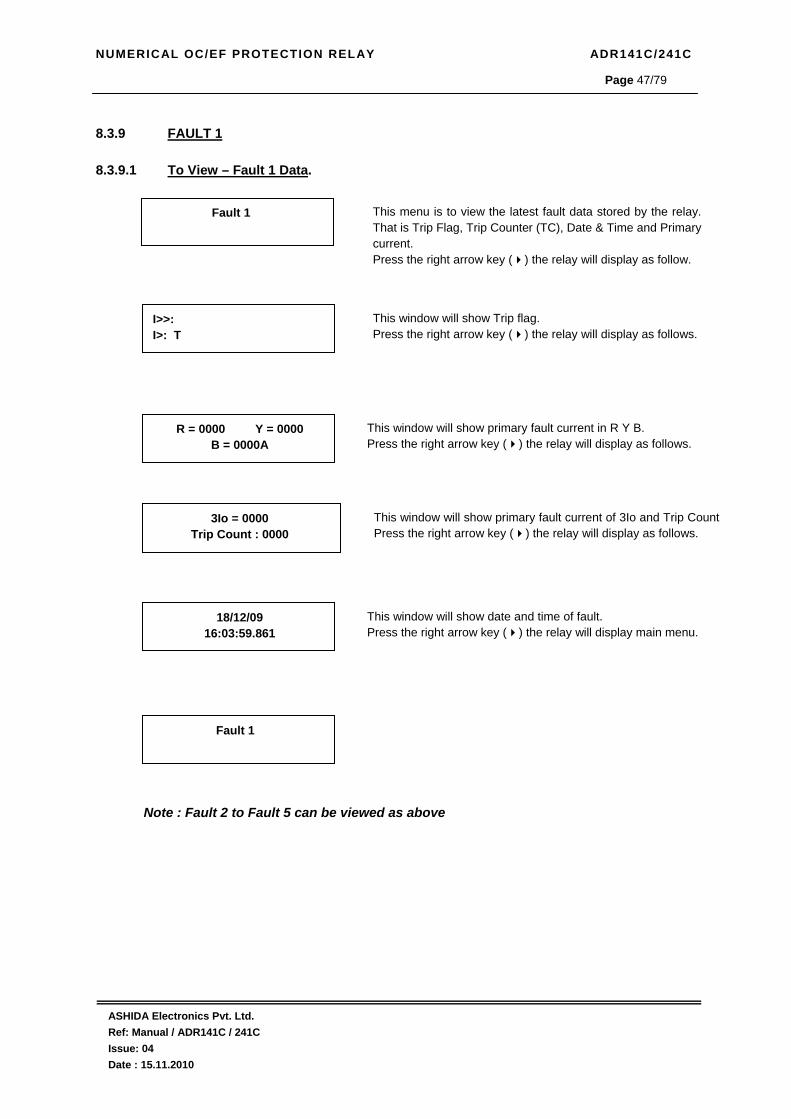
8.3.9 FAULT 1
8.3.9.1 To View – Fault 1 Data.
Note : Fault 2 to Fault 5 can be viewed as above
Fault 1
This menu is to view the latest fault data stored by the relay. That is Trip Flag, Trip Counter (TC), Date & Time and Primary current. Press the right arrow key ( ) the relay will display as follow.
I>>: I>: T
This window will show Trip flag. Press the right arrow key ( ) the relay will display as follows.
Fault 1
R = 0000 Y = 0000 B = 0000A
This window will show primary fault current in R Y B. Press the right arrow key ( ) the relay will display as follows.
3Io = 0000 Trip Count : 0000
This window will show primary fault current of 3Io and Trip Count Press the right arrow key ( ) the relay will display as follows.
18/12/09 16:03:59.861
This window will show date and time of fault. Press the right arrow key ( ) the relay will display main menu.

NUMERICAL OC/EF PROTECTION RELAY ADR141C/241C
ASHIDA Electronics Pvt. Ltd. Ref: Manual / ADR141C / 241C Issue: 04 Date : 15.11.2010
Page 48/79
8.3.10 ERROR LOG
8.3.10.1 To View – Error Log
8.3.11 STATUS
8.3.11.1 To View – Status
Error Log
This menu is to view the Error Log detected by the self supervision function of relay. Press the right arrow key ( ) the relay will display as follow.
Error Code : 0000
This window will show Error Code detected by self supervision function of Relay
Press the right arrow key ( ) the relay will display main menu.
Error Log
Status
This menu is to view the Status of Digital Input, Trip Circuit Supervision, circuit breaker and H/W / S/W version. Press the right arrow key ( ) the relay will display as follow.
CB NO: OFF CB NC: OFF
This window will show status of Digital Input i.e. CB NO and CB NC Press the right arrow key ( ) the relay will display as follow.
Status
Trip Ckt: Healthy Ckt Brker:?
This window will show status of Trip ckt. and ckt. Breaker. Press the right arrow key ( ) the relay will display as follows.
S/W V: 01.10 H/W V: 01.01
This window will shows the software and hardware version of relay Press the right arrow key ( ) the relay will display the main menu.

NUMERICAL OC/EF PROTECTION RELAY ADR141C/241C
ASHIDA Electronics Pvt. Ltd. Ref: Manual / ADR141C / 241C Issue: 04 Date : 15.11.2010
Page 49/79
8.3.12 DATE TIME SETTINGS
8.3.12.1 To Set – Date Time Setting
Date/Time
Password protected menu to set the Date and Time. Press the left arrow key ( ) the relay will display as follow.
Password = 001 Use INR/DEC
Enter the previously set password, by using the up arrow key ( + / ) or the down arrow key ( - / ). As per the Enter the Password selection. Press the left arrow key ( ) the relay will display as follow.
SET Hrs = 017 Range 0 – 23
By using the up arrow key ( + / ) or the down arrow key ( - / ) Hours can be set. The setting range is from 0-23 in steps of 1. Press the left arrow key ( ) the relay will display as follow.
SET Mins = 017 Range 0 – 59
By using the up arrow key ( + / ) or the down arrow key ( - / ) Minutes can be set. The setting range is from 0-59 in steps of 1. Press the left arrow key ( ) the relay will display as follow.
SET Sec = 017 Range 0 – 59
By using the up arrow key ( + / ) or the down arrow key ( - / ) Seconds can be set. The setting range is from 0-59 in steps of 1. Press the left arrow key ( ) the relay will display as follow.
SET Date = 017 Range 1 – 31
By using the up arrow key (+ / ) or the down arrow key ( - / ) Date can be set. The setting range is from 1-31 in steps of 1. Press the left arrow key ( ) the relay will display as follow.
SET Month = 004 Range 1 – 12
By using the up arrow key (+ / ) or the down arrow key ( - / ) Month can be set. The setting range is from 1-12 in steps of 1. Press the left arrow key ( ) the relay will display as follow.
SET Year = 008 Range 00 – 99
By using the up arrow key (+ / ) or the down arrow key ( - / ) Year can be set. The setting range is from 000-099 in steps of 001. Press the left arrow key ( ) the relay will display as follow.
Save Setting ? Mode For Save
To save any changes. Press the left arrow key ( ) the relay will save the change and the following message is display. Note: If changes made are not to be saved press LED Reset or leave key pad untouched for 100Sec.

NUMERICAL OC/EF PROTECTION RELAY ADR141C/241C
ASHIDA Electronics Pvt. Ltd. Ref: Manual / ADR141C / 241C Issue: 04 Date : 15.11.2010
Page 50/79
8.3.12.2 To View – Date Time Setting
8.3.13 Secondary Current 8.3.13.1 To View – Secondary Current
OK
This window will flash for moment The control will return to the main menu.
Date/Time
Date / Time
Press the right arrow key ( ) the relay will display as follow.
Time: 16: 40: 57 Date: 02/04/09
This window shows the Date and Time Press the right arrow key ( ) the relay will display the main menu.
Date / Time
Sec. Current
This menu is to view the actual secondary load current as per the CT Secondary selection. Press the right arrow key ( ) the relay will display as follow.
R = 00.00 Y = 00.00 B = 00.00
This window will show secondary load current of R,Y & B. Press the right arrow key ( ) the relay will display as follows.
Sec. Current
3Io = 00.00
This window will show secondary load current of 3Io. Press the right arrow key ( ) the relay will display as follows.

NUMERICAL OC/EF PROTECTION RELAY ADR141C/241C
ASHIDA Electronics Pvt. Ltd. Ref: Manual / ADR141C / 241C Issue: 04 Date : 15.11.2010
Page 51/79
9.0 MENU TABLE 9.1 To View – Primary Current
3Io = 0000A
R = 0000 Y = 0000 B = 0000A
Primary Current
R = 0000 Y = 0000 B = 0000A

NUMERICAL OC/EF PROTECTION RELAY ADR141C/241C
ASHIDA Electronics Pvt. Ltd. Ref: Manual / ADR141C / 241C Issue: 04 Date : 15.11.2010
Page 52/79
9.2 To Set & To View General Settings
BF Delay = 050 Range 50-800 ms
Password = 000 New Password
Password = 0000 Use Inr/Dec
CT Sec. = 001 1 = 1A , 2 = 5A
OK
Unit Id = 001
General Settings
Unit ID = 001
Test Block = NO Trip Ckt. = NO
Test Block = 002 01: Yes 02: N0
CT Primary = 0100 Range 10 - 3000
BF Enable = 002 01: Yes, 02: No
Trip Ckt. = 002 01: Yes, 02: No
CT Sec. = 01A CT Pri. = 0100A
BF Enable = No BF Delay = 050
Baud Rate = 57600 Range 1200 - 57600
Save Settings? Mode for Save
Baud Rate =57600
NUMERICAL OC/EF PROTECTION RELAY ADR141C/241C
ASHIDA Electronics Pvt. Ltd. Ref: Manual / ADR141C / 241C Issue: 04 Date : 15.11.2010
Page 53/79
9.3 To Set & To View Relay Settings
Ip> C6 Del = 04.1 Range 0.1 – 99.9s
Ip TMS = x1.00 Range x0.01 – 1.00
Ip> Enable = 002 01 : YES, 02 : NO
3Io> = 020 Range 10 – 250%
Save Settings ? Mode for Save
Ip>> = 016 Multiply by 50
Relay Settings
Ip> Enable = NO Ip>> Enable = NO
3Io> Enable = No 3Io>> Enable = No
Ip Curve = 002 Range C1 – C6
3Io>> Enable = 002 01 : YES, 02 : NO
Ip>> Delay = 0.01 Range 0 – 2.00s
Ip> 250% t=x1.00 Ip>> 0100% Ip> = 250
Range 10 – 250%
Password = 0000 Use Inr/Dec
3Io> Enable = 002 01 : YES, 02 : NO
Ip>> Enable = 002 01 : YES, 02 : NO
3Io>> = 016 Multiply by 50
3To TMS = x1.00 Range x0.01 – 1.00
3Io>> Delay = 0.01 Range 0 – 2.00s
3Io Curve = 002 Range C1 – C6
3Io> 250% t=x1.00 3Io>> 0100%
Ip>> Delay = 0.00 3Io>> Delay = 0.00
Ip> Normal Inv. 2 3Io> Normal Inv.1
Ip> C6 Del = 04.6 3Io> C6 Del = 00.7
3Io>C6 Del = 04.1 Range 0.1 – 99.9s
OK
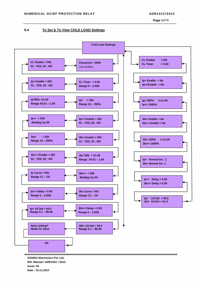
NUMERICAL OC/EF PROTECTION RELAY ADR141C/241C
ASHIDA Electronics Pvt. Ltd. Ref: Manual / ADR141C / 241C Issue: 04 Date : 15.11.2010
Page 54/79
9.4 To Set & To View COLD LOAD Settings
Ip>> Delay = 0.00 Range 0 – 2.00S
Ip> Enable = 002 01 : YES, 02 : NO
CL Enable = 002 01 : YES, 02 : NO
Ip>> = 020 Multiply by 50
3Io>> Delay = 0.00 Range 0 – 2.00S
IpTMS= X1.00 Range X0.01 – 1.00
Cold Load Settings
CL Enable = NO CL Timer = 0.50
Ip> 250% t=x1.00 Ip>> 1000%
3Io>> Enable = 002 01 : YES, 02 : NO
3Io> = 250 Range 10 – 250%
Ip Curve = 001 Range C1 – C6
Ip> Enable = No Ip>>Enable = No
CL Timer = 0.50 Range 0 – 2.00S
Password = 0000 Use Inr/Dec
Ip>> Enable = 002 01 : YES, 02 : NO
Ip> = 250 Range 10 – 250%
3Io TMS = X1.00 Range X0.01 – 1.00
3Io> Enable = 002 01 : YES, 02 : NO
3Io Curve = 001 Range C1 – C6
3Io>> = 020 Multiply by 50
3Io> Enable = No 3Io>> Enable = No
Ip> Normal Inv. 1 3Io> Normal Inv. 1
3Io> 250% t=x1.00 3Io>> 1000%
Ip>> Delay = 0.00 3Io>> Delay = 0.00
Ip> C6 Del = 00.5 Range 0.1 – 99.9S
3IO> C6 Del = 00.5 Range 0.1 – 99.9S
Save setting? Mode for Save
Ip> C6 Del = 00.5 3Io> C6 Del = 01.0
OK
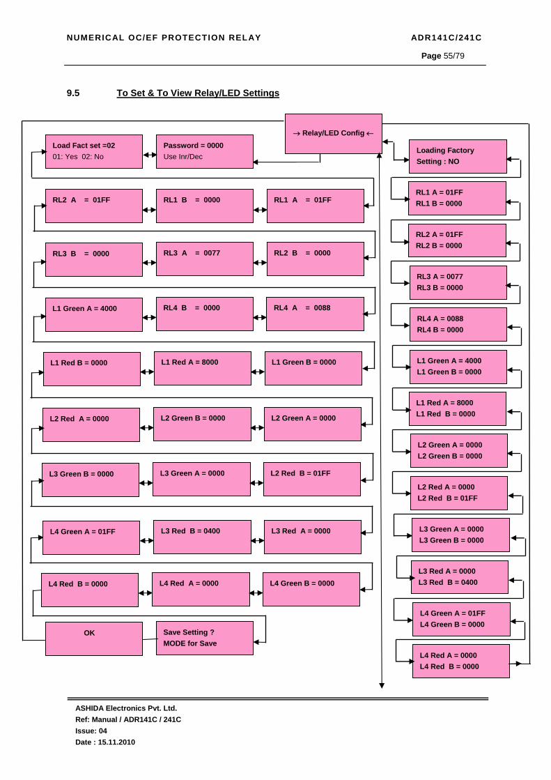
NUMERICAL OC/EF PROTECTION RELAY ADR141C/241C
ASHIDA Electronics Pvt. Ltd. Ref: Manual / ADR141C / 241C Issue: 04 Date : 15.11.2010
Page 55/79
9.5 To Set & To View Relay/LED Settings
→ Relay/LED Config ←
Loading Factory Setting : NO
RL1 A = 01FF RL1 B = 0000
RL2 A = 01FF RL2 B = 0000
RL3 B = 0000
RL3 A = 0077
RL2 B = 0000
L1 Green A = 4000
RL4 B = 0000
RL4 A = 0088
L4 Red B = 0000
L4 Red A = 0000
L4 Green B = 0000
RL3 A = 0077 RL3 B = 0000
RL4 A = 0088 RL4 B = 0000
Load Fact set =02 01: Yes 02: No
Password = 0000 Use Inr/Dec
RL1 B = 0000
RL2 A = 01FF
RL1 A = 01FF
L1 Red B = 0000
L1 Red A = 8000
L1 Green B = 0000
L2 Red A = 0000
L2 Green B = 0000
L2 Green A = 0000
L4 Green A = 01FF
L3 Red B = 0400
L3 Red A = 0000
L1 Red A = 8000 L1 Red B = 0000
L2 Green A = 0000 L2 Green B = 0000
L2 Red A = 0000 L2 Red B = 01FF
L3 Green B = 0000
L3 Green A = 0000
L2 Red B = 01FF
L1 Green A = 4000 L1 Green B = 0000
L3 Red A = 0000 L3 Red B = 0400
L4 Green A = 01FF L4 Green B = 0000
L4 Red A = 0000 L4 Red B = 0000
L3 Green A = 0000 L3 Green B = 0000
OK
Save Setting ? MODE for Save

NUMERICAL OC/EF PROTECTION RELAY ADR141C/241C
ASHIDA Electronics Pvt. Ltd. Ref: Manual / ADR141C / 241C Issue: 04 Date : 15.11.2010
Page 56/79
9.6 To View – TRIP TEST
Trip Test I>>:
I>: T
R=0000 Y=0000 B=0000A
3Io= 0000A Trip Count : 0000
22/11/09 16:53:21.058
Fault 1

NUMERICAL OC/EF PROTECTION RELAY ADR141C/241C
ASHIDA Electronics Pvt. Ltd. Ref: Manual / ADR141C / 241C Issue: 04 Date : 15.11.2010
Page 57/79
9.7 To View – Faults
Fault 1
I >> : I> : T
R = 0000 Y = 0000 B = 0000A
3Io = 0000A Trip Count : 0000
29/03/09 16:03:59.861
Fault 2
I >> : I> : T
R = 0000 Y = 0000 B = 0000A
3Io = 0000A Trip Count : 0000
29/03/09 16:03:59.861
Fault 3
I >> : I> : T
R = 0000 Y = 0000 B = 0000A
3Io = 0000A Trip Count : 0000
29/03/09 16:03:59.861
Fault 4
I >> : I> : T
R = 0000 Y = 0000 B = 0000A
3Io = 0000A Trip Count : 0000
29/03/09 16:03:59.861
Fault 5
I >> : I> : T
R = 0000 Y = 0000 B = 0000A
3Io = 0000A Trip Count : 0000
29/03/09 16:03:59.861
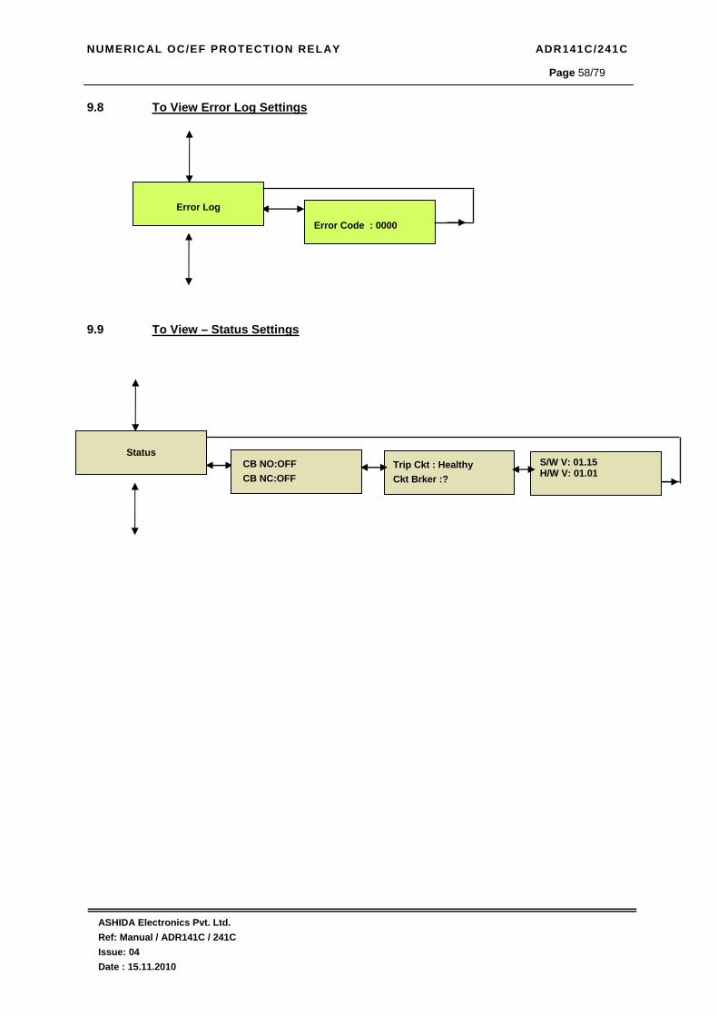
NUMERICAL OC/EF PROTECTION RELAY ADR141C/241C
ASHIDA Electronics Pvt. Ltd. Ref: Manual / ADR141C / 241C Issue: 04 Date : 15.11.2010
Page 58/79
9.8 To View Error Log Settings 9.9 To View – Status Settings
Error Log
Error Code : 0000
Status
CB NO:OFF CB NC:OFF
Trip Ckt : Healthy Ckt Brker :?
S/W V: 01.15 H/W V: 01.01

NUMERICAL OC/EF PROTECTION RELAY ADR141C/241C
ASHIDA Electronics Pvt. Ltd. Ref: Manual / ADR141C / 241C Issue: 04 Date : 15.11.2010
Page 59/79
9.10 To Adjust & To View Date/Time Settings
Password = 000 Use INR/DEC
SET Mins = 032 Range 0-59
SET Sec= 020 Range 0-59
SET Hrs = 04 Range 0-23
Date/Time
OK
Time : 04:32:20 Date : 27/08/10
Save Settings? Mode for Save
SET Year = 009 Range 00-99
SET Month : 004 Range 1-12
SET Date = 003 Range 1-31

NUMERICAL OC/EF PROTECTION RELAY ADR141C/241C
ASHIDA Electronics Pvt. Ltd. Ref: Manual / ADR141C / 241C Issue: 04 Date : 15.11.2010
Page 60/79
9.11 To View – Secondary Current
3Io = 00.00
R = 00.00 Y = 00.00 B = 00.00
Sec. Current
R = 00.00 Y = 00.00 B = 0000

NUMERICAL OC/EF PROTECTION RELAY ADR141C/241C
ASHIDA Electronics Pvt. Ltd. Ref: Manual / ADR141C / 241C Issue: 04 Date : 15.11.2010
Page 61/79
10.0 COMMUNICATION ( Only for ADR241C Relay ) 10.1 General
After every fault relay capture numbers of data which can be very useful to analysis fault.
Following is the summery of data which can be given by relay
1) Measurement value: The relay is connected to CT which samples the current signal and
calculates the number of different values from these signals. These values are available
whenever master demands. (Here master means connected PC or SCADA RTU) The
ADR241C gives RMS current information.
2) Event Value: Apart from basic protection functions. Relay is continuously monitors its
internal and external hardware through different status flags. There are two types of
status flags 1) Logical status such relay Pick-up, Relay, operation; setting change etc.
these are generated within relay. 2) Similarly there is opto-coupler inputs which are
connected to external contacts marked as S1 – S2. Any change in logical or physical
status is recorded as event. Such events are kept in internal non volatile memory along
with time stamp. Up to 100 such event can be store in relay memory. These events can
download for detailed analysis of any operation.
3) Fault History: After the fault, the relay latches all fault alongwith real time values these
are known as fault history. Last 5 fault history is available on relay display and on
communication port. Details of values are given in user interface
To read this fault information communication port are provided i.e. RS422 at rear. The relay
use 3 wire communication port. (RX, TX and GND) hand shaking signal are not used such
RTS, CTS, DSR DTR.

NUMERICAL OC/EF PROTECTION RELAY ADR141C/241C
ASHIDA Electronics Pvt. Ltd. Ref: Manual / ADR141C / 241C Issue: 04 Date : 15.11.2010
Page 62/79
10.2 General questions 10.2.1 What is meant by an event?
Event is nothing but every action performed by the relay. For e.g. status ON is one event and
status OFF is other event.
10.2.2 How can we read the events that are generated in the relay?
When the communication link is established between the PC and RS422 port of relay, then
events can be read on the PC through the SCADA software.
10.2.3 What is RS422?
RS422 is the communication port through which relay is communicates with PC through
SCADA software.
10.2.4 Where this port is located?
RS422 port is located at the rear side of the relay for permanent wiring of SCADA system. 10.2.5 Why RS422 port is used?
RS422 port is useful for long distance communication with unlikely any distortion in the
transmission and reception of data. The major advantage of RS422 Port is it is multidrop i.e.
upto 32 different devices can be connected to single port.
Convertor
Relay 1 Relay 2Differential Relay
Transformer Protection
Differential Relay Bus Bar
Protection
RS422 Data Bus
Central Control
Convertor
Relay 1 Relay 2Differential Relay
Transformer Protection
Differential Relay Bus Bar
Protection
RS422 Data Bus
Central Control
Convertor
Relay 1 Relay 2Differential Relay
Transformer Protection
Differential Relay Bus Bar
Protection
RS422 Data Bus
Central Control
Convertor
Relay 1 Relay 2Differential Relay
Transformer Protection
Differential Relay Bus Bar
Protection
RS422 Data Bus
Central Control 10.2.6 What is Relay Talk?
Relay Talk is software (Provided with this relay) which is installed in the PC. This software
provides you Communication Bridge between PC and Relay.
10.2.7 Why RS232 to RS485/422 ISOLATED CONVERTOR is used?
Generally PC is provided with RS232 port, to connect Relay with standard PC we need
RS232 to RS485/422 Isolated Convertor.
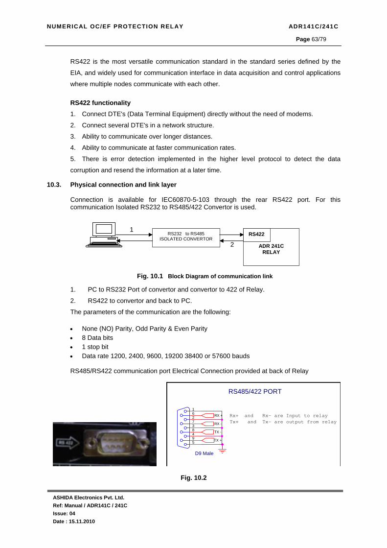
NUMERICAL OC/EF PROTECTION RELAY ADR141C/241C
ASHIDA Electronics Pvt. Ltd. Ref: Manual / ADR141C / 241C Issue: 04 Date : 15.11.2010
Page 63/79
RS422 is the most versatile communication standard in the standard series defined by the
EIA, and widely used for communication interface in data acquisition and control applications
where multiple nodes communicate with each other.
RS422 functionality 1. Connect DTE's (Data Terminal Equipment) directly without the need of modems.
2. Connect several DTE's in a network structure.
3. Ability to communicate over longer distances.
4. Ability to communicate at faster communication rates.
5. There is error detection implemented in the higher level protocol to detect the data
corruption and resend the information at a later time.
10.3. Physical connection and link layer
Connection is available for IEC60870-5-103 through the rear RS422 port. For this communication Isolated RS232 to RS485/422 Convertor is used. 1 2 Fig. 10.1 Block Diagram of communication link 1. PC to RS232 Port of convertor and convertor to 422 of Relay.
2. RS422 to convertor and back to PC.
The parameters of the communication are the following: • None (NO) Parity, Odd Parity & Even Parity • 8 Data bits • 1 stop bit • Data rate 1200, 2400, 9600, 19200 38400 or 57600 bauds
RS485/RS422 communication port Electrical Connection provided at back of Relay
RS485/422 PORT
D9 Male
594837261
RX -
RX +
TX +
TX -
Rx+ and Rx- are Input to relayTx+ and Tx- are output from relay
Fig. 10.2
RS232 to RS485 ISOLATED CONVERTOR
ADR 241C RELAY
RS422

NUMERICAL OC/EF PROTECTION RELAY ADR141C/241C
ASHIDA Electronics Pvt. Ltd. Ref: Manual / ADR141C / 241C Issue: 04 Date : 15.11.2010
Page 64/79
10.4. Relay Talk software for down loading the various data latch by relay, Following is a brief step by step instruction to down load relay data. • Start Relay Talk program from program menu
Following is the main screen of Relay talk system.
Fig. 10.3 For success communication setting of relay should match with software settings. In relay Talk
software there are numbers of settings. Here we have shown only essential screens for ADR241C
relay.
To check communication setting click configuration button.
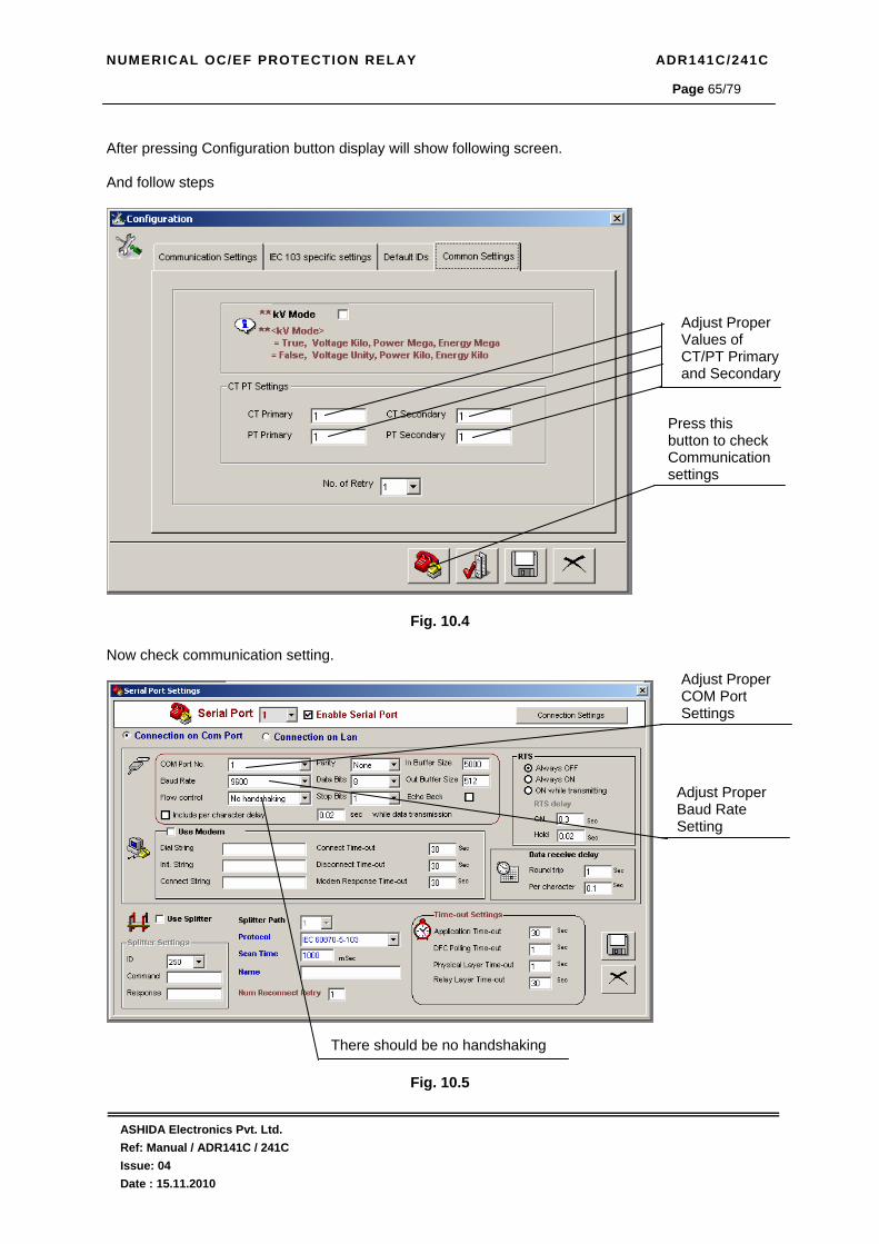
NUMERICAL OC/EF PROTECTION RELAY ADR141C/241C
ASHIDA Electronics Pvt. Ltd. Ref: Manual / ADR141C / 241C Issue: 04 Date : 15.11.2010
Page 65/79
After pressing Configuration button display will show following screen. And follow steps
Fig. 10.4 Now check communication setting.
Fig. 10.5
Adjust Proper Values of CT/PT Primary and Secondary
Press this button to check Communication settings
Adjust Proper COM Port Settings
Adjust Proper Baud Rate Setting
There should be no handshaking

NUMERICAL OC/EF PROTECTION RELAY ADR141C/241C
ASHIDA Electronics Pvt. Ltd. Ref: Manual / ADR141C / 241C Issue: 04 Date : 15.11.2010
Page 66/79
To finalise setting Press then Press & finally Press This will return to main screen. Default IDs settings Here we set the Default ID of the Relay.
Fig. 10.6
Relay ID

NUMERICAL OC/EF PROTECTION RELAY ADR141C/241C
ASHIDA Electronics Pvt. Ltd. Ref: Manual / ADR141C / 241C Issue: 04 Date : 15.11.2010
Page 67/79
Now select the path as shown in the window. i.e. IED ADR Series ADITYA V2 Series
ADITYA2_2
Fig. 10.7 Summary to ADR241C interface with relay talk system
1. Connect RS422 port on the back of ADR241C to PC through cable.
2. Check that relay setting will match to software configuration in serial port setting as well as
default ID setting as shown in figure.
3. Check unit ID, Parity, Com Port and Baud rate of ADR241C relay it should match to the
configuration of the software.
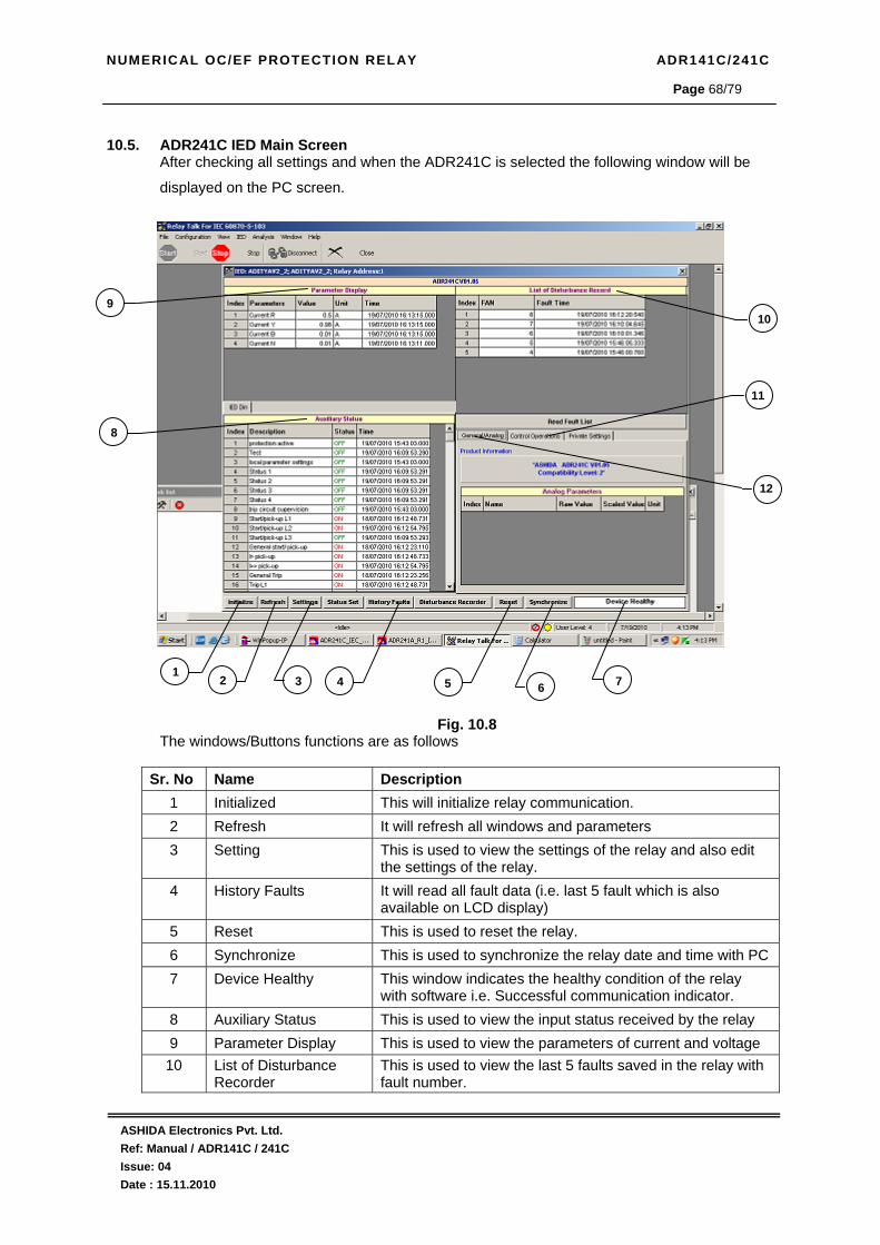
NUMERICAL OC/EF PROTECTION RELAY ADR141C/241C
ASHIDA Electronics Pvt. Ltd. Ref: Manual / ADR141C / 241C Issue: 04 Date : 15.11.2010
Page 68/79
10.5. ADR241C IED Main Screen After checking all settings and when the ADR241C is selected the following window will be
displayed on the PC screen.
Fig. 10.8 The windows/Buttons functions are as follows
Sr. No Name Description 1 Initialized This will initialize relay communication. 2 Refresh It will refresh all windows and parameters 3 Setting This is used to view the settings of the relay and also edit
the settings of the relay. 4 History Faults It will read all fault data (i.e. last 5 fault which is also
available on LCD display) 5 Reset This is used to reset the relay. 6 Synchronize This is used to synchronize the relay date and time with PC 7 Device Healthy This window indicates the healthy condition of the relay
with software i.e. Successful communication indicator. 8 Auxiliary Status This is used to view the input status received by the relay 9 Parameter Display This is used to view the parameters of current and voltage
10 List of Disturbance Recorder
This is used to view the last 5 faults saved in the relay with fault number.
10
12
11
6 7 5 1
2 3 4
8
9

NUMERICAL OC/EF PROTECTION RELAY ADR141C/241C
ASHIDA Electronics Pvt. Ltd. Ref: Manual / ADR141C / 241C Issue: 04 Date : 15.11.2010
Page 69/79
11 Control Operation This is used to operate relay control through operation from PC
12 General This is used to view Relay name, Version, and compatibility.
10.5.1 Parameter Display
Online Parameters along with their values in units are displayed along with the Date and Time
stamping and these are refreshed on successful communication.
Fig. 10.9
10.5.2 Physical/Logical Status Display (IEDs Din) These are physical/logical status (IED Dins), displayed along with there online status.
Fig. 10.10

NUMERICAL OC/EF PROTECTION RELAY ADR141C/241C
ASHIDA Electronics Pvt. Ltd. Ref: Manual / ADR141C / 241C Issue: 04 Date : 15.11.2010
Page 70/79
10.5.3 Control Operation
The control operation is used to control the relays parameters i.e. either to Reset the LEDs or
to open the CB by TRIP command.
Fig. 10.11
This window is not used in ADR241C This window is used to operate the controls
Fig. 10.12 Fig. 10.13
10.5.4 Private Setting
These settings for IEDs are displayed along with their current values and expected values.
Fig. 10.14

NUMERICAL OC/EF PROTECTION RELAY ADR141C/241C
ASHIDA Electronics Pvt. Ltd. Ref: Manual / ADR141C / 241C Issue: 04 Date : 15.11.2010
Page 71/79
10.6. History Fault Now when the History fault is selected the following window is displayed.
This window shows last 5 Fault events i.e. Trip Counter, Date & Time of the Faults, Type of
faults and present current values.
Fig. 10.15
The windows/Buttons functions are as follows
Sr. No. Name Description 1 Fault Buffer To view the fault buffer number 2 Read Fault To read the fault selected in the fault buffer 3 Refresh Fault To refresh all windows and parameters 4 Clear Fault display To clear the screen 5 Save Fault data To Save the Fault data 6 Close To close the History fault window
21
3 4 5 6

NUMERICAL OC/EF PROTECTION RELAY ADR141C/241C
ASHIDA Electronics Pvt. Ltd. Ref: Manual / ADR141C / 241C Issue: 04 Date : 15.11.2010
Page 72/79
10.7. Settings
This window is to view and edit the parameter of the relay. The setting are of two types
General Settings and Bank Settings.
10.7.1 General Settings
This window is to view and edit the parameters in general settings of the relay.
Fig. 10.16
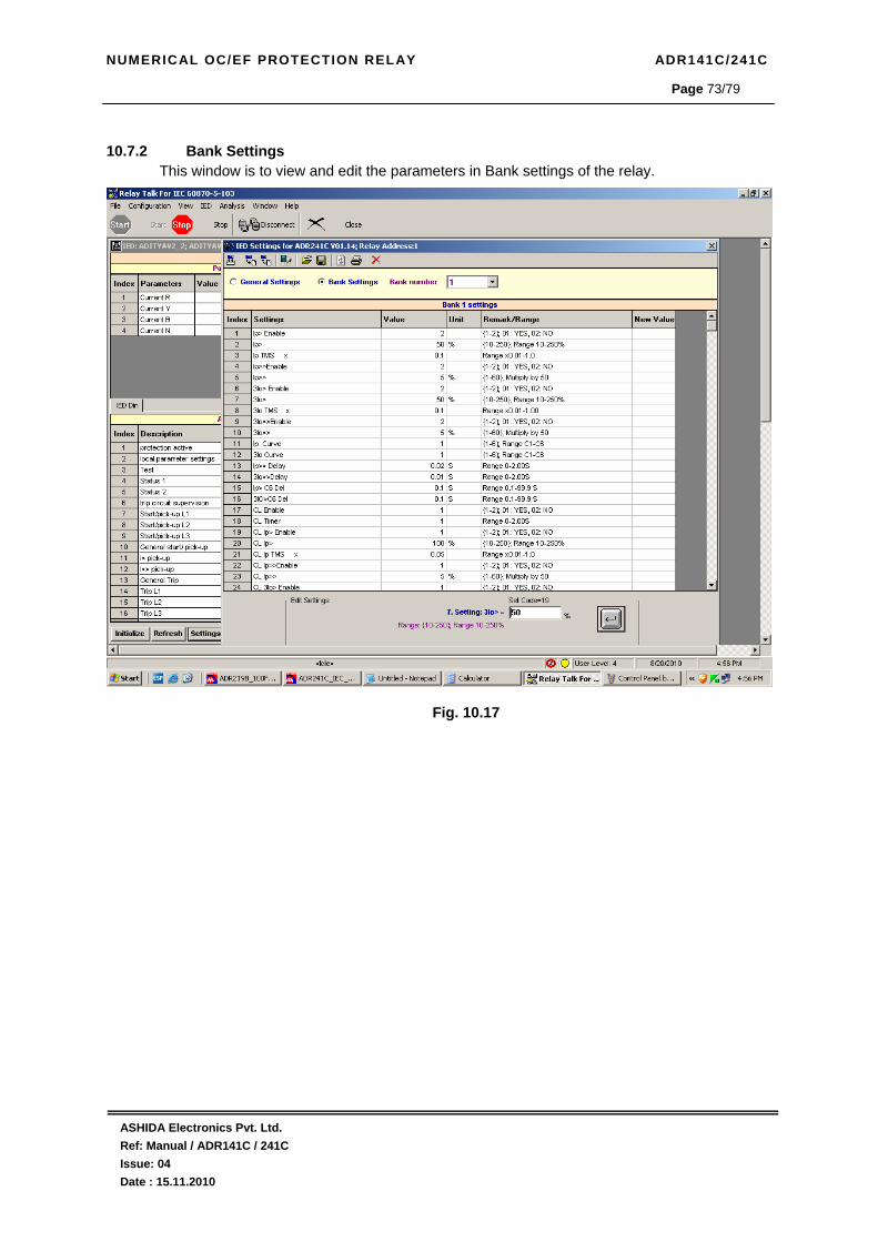
NUMERICAL OC/EF PROTECTION RELAY ADR141C/241C
ASHIDA Electronics Pvt. Ltd. Ref: Manual / ADR141C / 241C Issue: 04 Date : 15.11.2010
Page 73/79
10.7.2 Bank Settings
This window is to view and edit the parameters in Bank settings of the relay.
Fig. 10.17

NUMERICAL OC/EF PROTECTION RELAY ADR141C/241C
ASHIDA Electronics Pvt. Ltd. Ref: Manual / ADR141C / 241C Issue: 04 Date : 15.11.2010
Page 74/79
10.8. Event list
This window shows the all events generated in the relay. The following picture shows the auxiliary status and their event list.
Fig. 10.18
Fig. 10.19
3
1
2
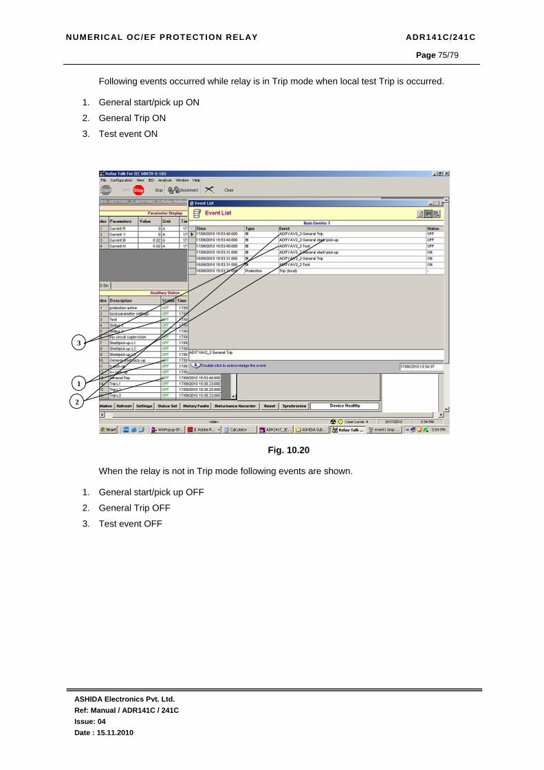
NUMERICAL OC/EF PROTECTION RELAY ADR141C/241C
ASHIDA Electronics Pvt. Ltd. Ref: Manual / ADR141C / 241C Issue: 04 Date : 15.11.2010
Page 75/79
Following events occurred while relay is in Trip mode when local test Trip is occurred.
1. General start/pick up ON
2. General Trip ON
3. Test event ON
Fig. 10.20 When the relay is not in Trip mode following events are shown.
1. General start/pick up OFF
2. General Trip OFF
3. Test event OFF
3
1
2
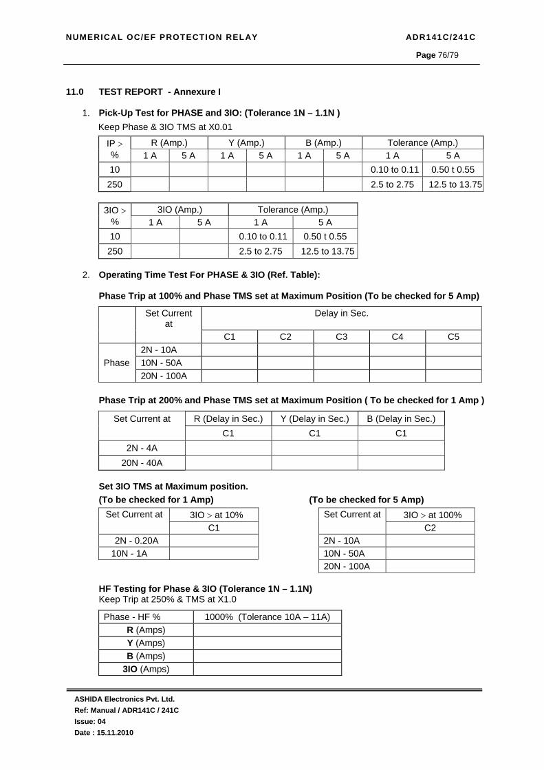
NUMERICAL OC/EF PROTECTION RELAY ADR141C/241C
ASHIDA Electronics Pvt. Ltd. Ref: Manual / ADR141C / 241C Issue: 04 Date : 15.11.2010
Page 76/79
11.0 TEST REPORT - Annexure I
1. Pick-Up Test for PHASE and 3IO: (Tolerance 1N – 1.1N ) Keep Phase & 3IO TMS at X0.01
R (Amp.) Y (Amp.) B (Amp.) Tolerance (Amp.) IP > % 1 A 5 A 1 A 5 A 1 A 5 A 1 A 5 A 10 0.10 to 0.11 0.50 t 0.55
250 2.5 to 2.75 12.5 to 13.75
3IO (Amp.) Tolerance (Amp.) 3IO > % 1 A 5 A 1 A 5 A 10 0.10 to 0.11 0.50 t 0.55 250 2.5 to 2.75 12.5 to 13.75
2. Operating Time Test For PHASE & 3IO (Ref. Table):
Phase Trip at 100% and Phase TMS set at Maximum Position (To be checked for 5 Amp)
Set Current at
Delay in Sec.
C1 C2 C3 C4 C5 2N - 10A Phase 10N - 50A 20N - 100A
Phase Trip at 200% and Phase TMS set at Maximum Position ( To be checked for 1 Amp )
Set Current at R (Delay in Sec.) Y (Delay in Sec.) B (Delay in Sec.) C1 C1 C1
2N - 4A 20N - 40A
Set 3IO TMS at Maximum position. (To be checked for 1 Amp) (To be checked for 5 Amp)
Set Current at 3IO > at 10% Set Current at 3IO > at 100% C1 C2
2N - 0.20A 2N - 10A 10N - 1A 10N - 50A
20N - 100A
HF Testing for Phase & 3IO (Tolerance 1N – 1.1N) Keep Trip at 250% & TMS at X1.0
Phase - HF % 1000% (Tolerance 10A – 11A) R (Amps) Y (Amps) B (Amps)
3IO (Amps)

NUMERICAL OC/EF PROTECTION RELAY ADR141C/241C
ASHIDA Electronics Pvt. Ltd. Ref: Manual / ADR141C / 241C Issue: 04 Date : 15.11.2010
Page 77/79
HF Time Delay Testing For PHASE & 3IO (Adjust Current 2N to Trip Relay with HF): (Actual Delay = Inst. + Set Delay) HF Time Delay settings 00(Inst.) 0.06 2.0 Observed Delay(Phase) Observed Delay(3IO) Tolerance = Inst. + ( ± 5% of Set ) ≤40 ms
Definite Time Delay Testing For PHASE & 3IO (Curve 6) (Adjust Current 1.5N of pickup setting):
Definite Time delay settings 0.5 10.0 Observed Delay(Phase)
Observed Delay(3IO) Tolerance ± 5% 0.475 to 0.525 9.5 to 10.5
3. Breaker Fail (LBB) Time Test:
Set BF Delay (mSecs) 100 400 800
Observed delay (mSecs)
4. Key functions: ____________________ . 5. Relay contacts: _______________. 6. Back Terminal Connection: _______________________________.
7. Insulation test: __________________MΩ @ 1000VDC.
8. H.V. Test: @ 2000VAC between all Terminals and body for 60 Sec. _____________. 9. RS 485 Communication:______________________ 10. Conclusion: _________________________________________________________.
Tested By Checked By (QC)


NUMERICAL OC/EF PROTECTION RELAY ADR141C/241C
ASHIDA Electronics Pvt. Ltd. Ref: Manual / ADR141C / 241C Issue: 04 Date : 15.11.2010
Page 79/79
12.0 Revision Note
Issue Date Description
01 06.03.2010 Original Version
02 26.08.2010 Communication Details added
03 03.09.2010 Test Report added.
04 15.11.2010 Software Version Changed