numerical prediction of the propagation of branched...
TRANSCRIPT
432
Numerical prediction of the propagation of branched fatigue cracks
M.A. Meggiolaro a,∗, A.C.O. Miranda b, J.T.P. Castro a, L.F. Martha b
a Mechanical Engineering Department, Pontifical Catholic University, Rio de Janeiro, RJ 22453-900, Brazilb Civil Engineering Department, Pontifical Catholic University, Rio de Janeiro, RJ 22453-900, Brazil
Abstract
A specialized finite element (FE) program is used to predict the propagation behavior of asymmetrically bifurcatedcracks, which can cause crack growth retardation and arrest. The branched crack propagation path and associated stressintensity factors (SIF) are obtained for several bifurcation angles. It is found that very small differences between the branchlengths are enough to cause the shorter one to eventually arrest due to shielding effects. The SIF of the longer crack branchis also reduced due to the deflections, but it returns to the original non-bifurcated value as the crack propagates away fromthe influence of the (arrested) shorter branch. It is verified that crack bifurcation may provide an alternate mechanisticexplanation for overload-induced crack retardation.
Keywords: Fatigue; Crack propagation; Crack path; Branched cracks; Overloads; Finite elements
1. Introduction
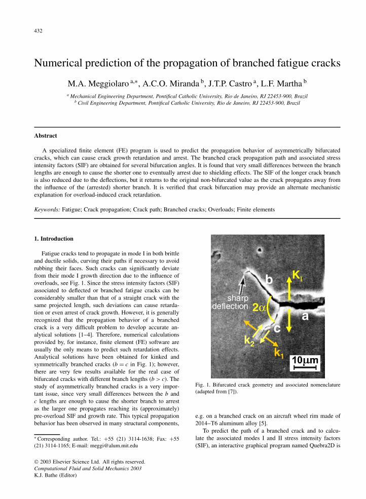
Fatigue cracks tend to propagate in mode I in both brittleand ductile solids, curving their paths if necessary to avoidrubbing their faces. Such cracks can significantly deviatefrom their mode I growth direction due to the influence ofoverloads, see Fig. 1. Since the stress intensity factors (SIF)associated to deflected or branched fatigue cracks can beconsiderably smaller than that of a straight crack with thesame projected length, such deviations can cause retarda-tion or even arrest of crack growth. However, it is generallyrecognized that the propagation behavior of a branchedcrack is a very difficult problem to develop accurate an-alytical solutions [1–4]. Therefore, numerical calculationsprovided by, for instance, finite element (FE) software areusually the only means to predict such retardation effects.Analytical solutions have been obtained for kinked andsymmetrically branched cracks (b = c in Fig. 1); however,there are very few results available for the real case ofbifurcated cracks with different branch lengths (b > c). Thestudy of asymmetrically branched cracks is a very impor-tant issue, since very small differences between the b andc lengths are enough to cause the shorter branch to arrestas the larger one propagates reaching its (approximately)pre-overload SIF and growth rate. This typical propagationbehavior has been observed in many structural components,
∗ Corresponding author. Tel.: +55 (21) 3114-1638; Fax: +55(21) 3114-1165; E-mail: [email protected]
2α
b
ca
k1
k2
KI
sharpdeflection
Fig. 1. Bifurcated crack geometry and associated nomenclature(adapted from [7]).
e.g. on a branched crack on an aircraft wheel rim made of2014–T6 aluminum alloy [5].
To predict the path of a branched crack and to calcu-late the associated modes I and II stress intensity factors(SIF), an interactive graphical program named Quebra2D is
2003 Elsevier Science Ltd. All rights reserved.Computational Fluid and Solid Mechanics 2003K.J. Bathe (Editor)

M.A. Meggiolaro et al. / Second MIT Conference on Computational Fluid and Solid Mechanics 433
used. This program simulates two-dimensional fracture pro-cesses based on a finite-element (FE) self-adaptive mesh-generation strategy, using appropriate crack tip elementsand crack increment criteria. It has been validated throughexperiments on several modified CT specimens and fromcomparisons with analytical solutions for kinked cracks [6].In the next section, this FE software is used to calculate thepropagation behavior of bifurcated (branched) cracks.
2. Propagation of branched cracks
The propagation of branched cracks is studied using aFE model of a standard CT specimen with width w = 32.0mm and crack length a = 14.9 mm, with a bifurcation atthe crack tip with branch lengths b = 11 µm and c = 10µm (see Fig. 1). The bifurcation angles 2α considered inthis study vary between 60° and 150°, which are character-istic values for experimentally obtained overload-inducedbranched cracks [7].
To calculate the propagation path in the Quebra2D pro-gram, three criteria are used for the numerical computationof the crack incremental growth direction in the linear-elastic regime: the maximum circumferential stress (σθ max),the maximum potential energy release rate (Gθ max), and theminimum strain energy density (Sθ min) [6]. Bittencourt etal. [8] have shown that if the crack orientation is allowed tochange in automatic fracture simulation, the three criteriabasically provide the same numerical results. A fixed crackgrowth step of 3 µm is considered for the propagation ofthe longer branch, calculated in the direction defined bythe σθ max criterion (which is the criterion adopted in thissimulation due to its simplicity and to the availability ofclosed form solutions). However, due to the differences inthe crack growth rate, a smaller growth step is expected forthe shorter branch. This smaller step is obtained assuminga crack propagation law that models the first two growthregimes,
da
dN= A · (∆K −∆Kth)m (1)
where A and m are material constants and ∆Kth is thepropagation threshold. If ∆K and ∆K ′ are respectively thestress intensity ranges of the longer and shorter branches,then the growth step ∆a of the shorter branch should be
∆a = 3 µm ·(
∆K ′ −∆Kth
∆K −∆Kth
)m
(2)
Interestingly, the ratio between the propagation rates ofthe two branches is independent of the material constantA. In this analysis, ∆Kth and the exponent m are as-sumed to be respectively 10 MPa
√m and 3.0, which are
representative values for steels at low R ratios.It must be noted however that linear-elastic FE calcu-
lations can only lead to accurate solutions if the lengthsof the crack branches (b and c in Fig. 1) are significantly
larger than the size scale of both the microstructure and thenear-tip plastic (or process) zone. But as the crack branchesgrow further, the FE method can give a reasonable esti-mate of their behavior, in special for brittle or semi-brittlematerials with small process zones. In addition, the growthof branched cracks is typically transgranular, as verifiedfrom optical microscope observations performed by Shi etal. [9], which is one of the requirements to allow for thesimulation of fatigue behavior in an isotropic linear-elasticregime.
3. Results
Fig. 2 shows the mode I SIF k1 at the tip of eachcrack branch (normalized by the mode I SIF K I of astraight crack) as a function of the length b of the longerbranch, measured along the propagation path. Because ofthe different crack lengths, the SIF at the larger crack tipis much higher than that at the shorter branch. Assumingk1 to be the crack driving force, it can be seen from Fig. 2that the longer branch reaches its minimum propagationrate right after the bifurcation occurs, returning to its pre-overload rate as the crack tip advances away from theinfluence of the (probably arrested) shorter branch. Also,the mode I SIF of the shorter branch is progressivelyreduced due to shielding effects, resulting in crack arrestas the propagation threshold ∆Kth is reached. Note thateven small differences between the branch lengths (suchas 1 µm) are sufficient to cause subsequent arrest of theshorter branch (Fig. 3). In addition, the retardation effectlasts longer for larger bifurcation angles (Fig. 3), not onlybecause the associated mode I SIF is smaller, but alsobecause the shielding effect is weaker since both branchtips are further apart, delaying the arrest of the shorter one.
Another interesting conclusion is that the initial prop-agation direction of the longer branch is always between25° and 30° (with respect to the pre-overload growth direc-tion), independently of the considered bifurcation angle 2α.Therefore, for larger values of 2α, a sharp deflection canbe clearly noted in the beginning of the propagation. Thisdeflection has been confirmed experimentally by Lankfordand Davidson [7], who carried out overload fatigue cracktests on a 6061–T6 aluminum alloy in a scanning electronmicroscope using a special in-situ servo-controlled hy-draulic loading stage, obtaining growth retardation causedby crack bifurcation. They have found that the bifurcatedcrack would grow only a short distance in the same di-rection of the overload-induced bifurcation before a sharpdeflection in the crack path would occur, see Fig. 1. Thisdeflection causes a sudden increase in k1 almost immedi-ately after the propagation begins (Fig. 2), resulting in asignificantly smaller retardation effect if compared to sim-plistic predictions based on symmetrically branched cracksolutions found in the literature. However, if the SIF of

434 M.A. Meggiolaro et al. / Second MIT Conference on Computational Fluid and Solid Mechanics
0.5
0.6
0.7
0.8
0.9
1
0 10 20 30 40 50 60longer branch length b (µm)
k 1/K
I (lo
ng
er b
ran
ch)
60o
90o
120o
150o
bifurcation
sharp deflection
bifurcationangle 2α:
2α
b
c
a
k1
0
0.2
0.4
0.6
0.8
1
0 10 20 30 40 50 60longer branch length b ( µm)
k 1/K
I (sh
ort
er b
ran
ch)
60o
90o
120o
150o
bifurcationangle 2α:
bifurcation
arrest of shorter branch
2α
b
c
a
k1
Fig. 2. Normalized mode I stress intensity factors for the longer (top) and shorter (bottom) branches of a bifurcated crack during itspropagation.
0
10
20
30
40
0 10 20 30 40 50 60
longer branch length b (µm)
sho
rter
bra
nch
len
gth
c (
µm)
60o
90o
120o
150o
bifurcationangle 2α:
bifurcation
arrest of shorter branch
2α
b
c
a
Fig. 3. Crack lengths of both branches of a bifurcated crack during its propagation, always resulting in crack arrest for the shorter branch.
both branches is below ∆Kth , then the entire crack arrestsand therefore no sharp deflection has the chance to bedeveloped.
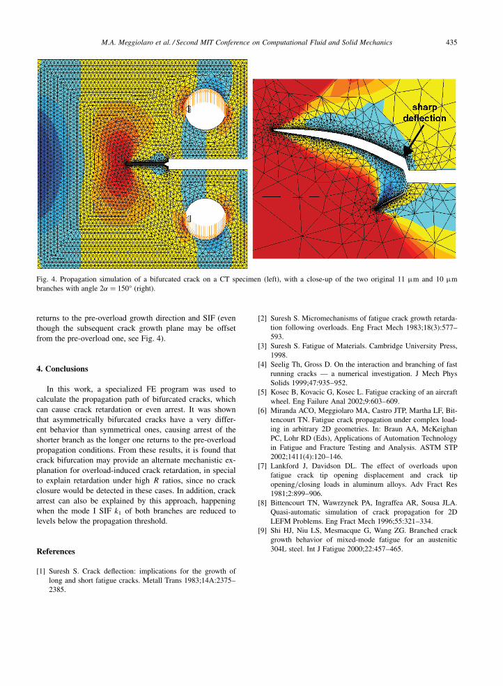
Finally, Fig. 4 shows the propagation results for a bi-furcated crack with angle 2α = 150°. In this figure, the
deformations are amplified to better visualize the crackpath. Note that the crack path deviates from the origi-nal branch angles, deflecting from ±75° to approximately±28°. In addition, the originally shorter branch arrests af-ter propagating to (only) 39 µm, while the longer branch
M.A. Meggiolaro et al. / Second MIT Conference on Computational Fluid and Solid Mechanics 435
Fig. 4. Propagation simulation of a bifurcated crack on a CT specimen (left), with a close-up of the two original 11 µm and 10 µmbranches with angle 2α = 150° (right).
returns to the pre-overload growth direction and SIF (eventhough the subsequent crack growth plane may be offsetfrom the pre-overload one, see Fig. 4).
4. Conclusions
In this work, a specialized FE program was used tocalculate the propagation path of bifurcated cracks, whichcan cause crack retardation or even arrest. It was shownthat asymmetrically bifurcated cracks have a very differ-ent behavior than symmetrical ones, causing arrest of theshorter branch as the longer one returns to the pre-overloadpropagation conditions. From these results, it is found thatcrack bifurcation may provide an alternate mechanistic ex-planation for overload-induced crack retardation, in specialto explain retardation under high R ratios, since no crackclosure would be detected in these cases. In addition, crackarrest can also be explained by this approach, happeningwhen the mode I SIF k1 of both branches are reduced tolevels below the propagation threshold.
References
[1] Suresh S. Crack deflection: implications for the growth oflong and short fatigue cracks. Metall Trans 1983;14A:2375–2385.
[2] Suresh S. Micromechanisms of fatigue crack growth retarda-tion following overloads. Eng Fract Mech 1983;18(3):577–593.
[3] Suresh S. Fatigue of Materials. Cambridge University Press,1998.
[4] Seelig Th, Gross D. On the interaction and branching of fastrunning cracks — a numerical investigation. J Mech PhysSolids 1999;47:935–952.
[5] Kosec B, Kovacic G, Kosec L. Fatigue cracking of an aircraftwheel. Eng Failure Anal 2002;9:603–609.
[6] Miranda ACO, Meggiolaro MA, Castro JTP, Martha LF, Bit-tencourt TN. Fatigue crack propagation under complex load-ing in arbitrary 2D geometries. In: Braun AA, McKeighanPC, Lohr RD (Eds), Applications of Automation Technologyin Fatigue and Fracture Testing and Analysis. ASTM STP2002;1411(4):120–146.
[7] Lankford J, Davidson DL. The effect of overloads uponfatigue crack tip opening displacement and crack tipopening/closing loads in aluminum alloys. Adv Fract Res1981;2:899–906.
[8] Bittencourt TN, Wawrzynek PA, Ingraffea AR, Sousa JLA.Quasi-automatic simulation of crack propagation for 2DLEFM Problems. Eng Fract Mech 1996;55:321–334.
[9] Shi HJ, Niu LS, Mesmacque G, Wang ZG. Branched crackgrowth behavior of mixed-mode fatigue for an austenitic304L steel. Int J Fatigue 2000;22:457–465.