nureg/cr-0488, 'nuclear power plant fire protection fire ... · nuclear power plant fire...
TRANSCRIPT

NUREG/CR-0488SAND78-1373
RP
Nuclear Power Plant Fire ProtectionFire Detection(Subsystems Study Task 2)
Dennis L. Berry
Manuscript Submitted: December 1977Date Published: March 1979
Sandia National LaboratoriesAlbuquerque, NM 87185Operated bySandia Corporationfor theU. S. Department of Energy
Prepared forEngineering Methodology Standards BranchOffice of Standards DevelopmentU. S. Nuclear Regulatory CommissionWashington, D.C. 20555Under Interagency Agreement DOE 40-550-75NRC FIN No. A-1080
~pR REGtQzl,
CCO


NUREG/CR-0488SAND78-1373
RP
NUCLEAR POWER PLANT FIRE PROTECTIONFIRE DETECTION (SUBSYSTEMS STUDY TASK 2)
Dennis L. Berry
Manuscript Submitted: December 1977
Date Published: March 1979
Sandia LaboratoriesAlbuquerque, NM 87185
operated bySandia Corporation
for theU. S. Department of Energy
Prepared forEngineering Methodology Standards Branch
Office of Standards DevelopmentU. S. Nuclear Regulatory Commission
Washington, DC 20555Under Interagency Agreement DOE 40-550-75
NRC FIN No. A-1080
3-4

ABSTRACT
This report examines the adequacy of fire detection in thecontext of nuclear power plant safety. Topics considered are:(1) establishing area detection requirements, (2) selectingspecific detector types, (3) locating and spacing detectors, and(4) performing installation tests and maintenance. Based on athorough review of fire detection codes and standards and firedetection literature, the report concludes that current designand regulatory guidelines alone are insufficient to ensuresatisfactory fire detection system performance. To assureadequate fire detection, this report recommends the use of in-place testing of detectors under conditions expected to occurnormally in areas being protected.
5-6

CONTENTS
Page
I. SUMMARY 9
II. INTRODUCTION 10
A. Background 10
B. Task 2 Description 10
III, DISCUSSION 13
A. Establishing Area Detection Requirements 14
B. Selecting Specific Detector Types 19
C. Locating and Spacing Detectors 28
D. Performing Installation Tests and Maintenance 40
IV. CONCLUSIONS 45
V. RECOMMENDATIONS 47
A. Establishing Area Detection Requirements 47
B. Selecting Specific Detector Types 48
C. Locating and Spacing Detectors 49
D. Performing Installation Tests and Maintenance 49
VI. REFERENCES 51
APPENDIX A - Confusion Over Class A System Designation 53
APPENDIX B - Abbreviated Description of Commercially AvailableDetectors 55
7

Figure
1
ILLUSTRATIONS
Flow Chart for Detector Selection
TABLES
Information Sources Reviewed and Corresponding
Evaluation Categories
Page
25
Table
I
II Relationship Between Design and Maintenance Activitiesand Evaluation Categories
III Area Detection Guidelines
IV Physical Characteristics of Selected Safety-RelatedPlant Areas as Related to Detector Selection
V Comparison of Detector Location and Spacing Criteriawith Governing Design Guidance Quoted from NFPA 72 E
VI Advantages and Disadvantages of Performing DetectorTesting and Maintenance According to Manufacturer'sRecommendations
12
13
16
24
31
44
8
NUCLEAR POWER PLANT FIRE PROTECTIONFIRE DETECTION (SUBSYSTEMS STUDY TASK 2)
I. SUMMARY
'An uncontrolled fire in a nuclear power plant can seriously jeopar-
dize overall plant safety. Recognizing this, the Nuclear Regulatory Com-
mission has undertaken a broad program in fire protection research, a por-
tion of which focuses on early fire detection. This report examines the
adequacy of fire detection in the context of nuclear power plant safety.
Because of the expanse of'a nuclear power plant and the normally
limited number of resident operating personnel, remote automatic fire
detection represents the only viable method of providing early fire
warning for most plant areas. By installing throughout a power plant
devices which are sensitive to fire and by electrically connecting these
devices to centralized alarm panels, operators can receive fire warnings
from anywhere in the plant. The reliability of such a system, however,
depends upon correct design and maintenance.
Traditionally, nuclear power plant designers have utilized a
combination of fire codes, test standards, fire consultant recommenda-
tions, insurance agency requests, and detector vendor suggestions to
formulate the design of fire detection systems. Proceeding in this
manner, designers often apply detection principles to nuclear power plants
which have been proven in residential and commercial installations.
However, because the ventilation conditions, ceiling heights, ceiling
construction, and types of combustibles existing in nuclear power plants
can differ from those used elsewhere, it is difficult to show that
traditional detection system design approaches will be adequate for
9
nuclear power plants. Also, it is doubtful whether any theory can be
developed and proven in the near future to describe the effects of
different installation conditions on detection system operation.
Therefore, it appears that the best approach to solving the uncer-
tainties of nuclear power plant fire detection is through in-place testing
of detectors under environmental conditions anticipated to occur normally
in each area being protected. Through in-place testing, during both
initial installation and subsequent maintenance intervals, satisfactory
detection performance can be assured for the variety of conditions found
in nuclear power plants.
II., INTRODUCTION
A. Background
An earlier Sandia Laboratories fire protection system study1
concluded that much progrers can be made to enhance fire detection effec-
tiveness in nuclear power plants by clarifying fire detection design
requirements and by adapting existing detection techniques. This conclu-
sion had been based on both the ready availability of numerous detection
devices currently on the market and the lack of adequate design guidance
for selecting, locating, testing, and maintaining detection system hard-
ware. Based on these findings, the Nuclear Regulatory Commission decided
to undertake a more thorough review of fire detection, as part of a second
study addressing several major areas of fire protection. Task 1 of this
new study addressed ventilation, while Tasks 3 and 4, to be completed
later, will involve fire barriers and fire hazards analysis. Task 2, fire
detectors, is the subject of this report.
B. Task 2 Description
The fire detection subsystem review was undertaken to evaluate the
following .from the standpoint of overall plant safety:
a. the technical bases for detection system design criteria,
10

b. the adequacy of detailed design guidance currently avail-
able, and
c. the effectiveness of qualification testing procedures to
simulate actual design applications.
For each of these three evaluation categories, numerous recognized fire
protection information sources were chosen for review. The assignment of
each information source to an appropriate evaluation category is shown in
Table 1 and is based upon the level of detail and scope of information
available in each source.
After establishing evaluation categories and information sources, it
was decided to.focus on the selection and use of detector sensing units,
rather than to investigate either the internal design details of the units
or the operation of each ancillary detection system component (i.e., trans-
mitters, alarm units, satellite stations, or interconnecting wiring). This
decision stemmed from a realization that:
1. Existing detection theory lacks the ability to predict
detector performance solely from known internal sensing
unit design features.
2. Ancillary detection system components primarily function
to transmit electrical signals from detector sensing units
to various panels and alarm devices, generally through the
use of fundamental electrical design techniques which have
been accepted and used extensively throughout other nuclear
power plant systems.
*One exception to this observation is cited in Appendix A of the
report.
11

TABLE I
Information Sources Reviewed and Corresponding Evaluation Categories
Evaluation CategoriesInformation
Sources Design Design QualificationReviewed Criteria Details Tests
Nuclear Regulatory Commission
Documents x*
Insurance Agency Documents x
National Fire Protection Codes x
Underwriters Laboratories Tests x
Vendor Information and OpenLiterature (where applicable) x x x
*x refers to the primary charter of the cited information source
Based on these observations, the following design and maintenance
activities related to the selecting and use of detector sensing units were
chosen for review:
" Establishing area detection requirements
" Selecting specific detector types
" Locating and spacing detectors
" Performing installation tests and maintenance.
As illustrated in Table II, this report separately addresses each of these
activities for commercially available detector sensing units and, in so
doing, questions the adequacy of applicable design criteria, design
details, and qualification testing.
12
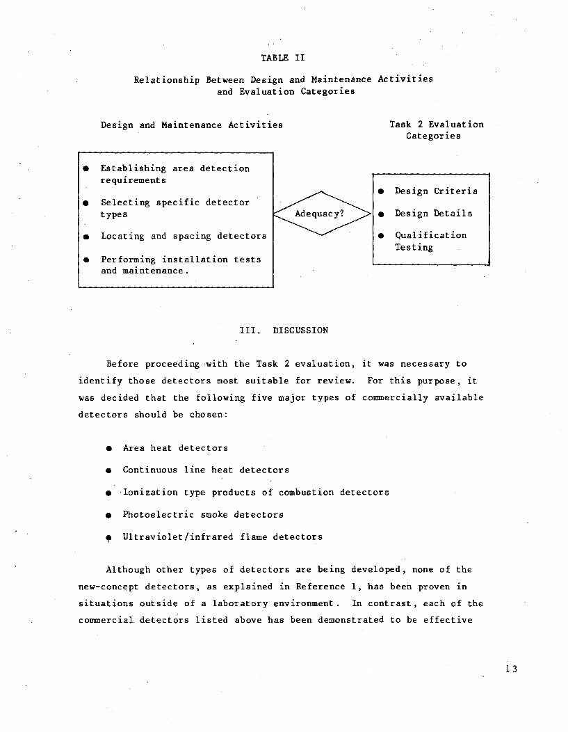
TABLE II
Relationship Between Design and Maintenance Activitiesand Evaluation Categories
Design and Maintenance Activities
0 Establishing area detectionrequirements
* Selecting specific detectortypes
" Locating and spacing detectors
* Performing installation testsand maintenance.
AdequacIy?
DISCUSSION
Task 2 EvaluationCategories
* Design Criteria
" Design Details
" QualificationTesting
III.
Before proceeding with the Task 2 evaluation,
identify those detectors most suitable for review.
was decided that the following five major types of
detectors should be chosen:
it was necessary to
For this purpose, it
commercially available
" Area heat detectors
" Continuous line heat detectors
e Ionization type products of combustion detectors
* Photoelectric smoke detectors
Ultraviolet/infrared flame detectors
Although other types of detectors are being developed, none of the
new-concept detectors, as explained in Reference 1, has been proven in
situations outside of a laboratory environment. In contrast, each of the
commercial, detectors listed above has been demonstrated to be effective
13
when installed and maintained in a manner consistent with its governing
qualification tests.
A. Establishing Area Detection Requirements
The first decision that must be reached regarding fire detection is
whether or not automatic detection is required for a particular power
plant area. To make this decision from a plant safety viewpoint, a
careful assessment of automatic detection must be made on the basis of
many factors, including:
" Importance of the area to overall plant safety
" Susceptibility of the area to surrounding fire hazards
e Degree of fire hazard within the area
e Potential of fire spreading to other areas
e Type of available fire suppression (e.g., manual or
automatic; inert gas or water)
* Cost of added detection capability
* Normal occupancy of the area
Unfortunately, it is not always possible to assess all of these factors
objectively for each area of a nuclear power plant, and, because of this,
detection requirements generally have been designated on the basis of an
area's safety importance, regardless of the actual fire risk associated
with the area. One possible exception to this practice occurs in those
instances where detection requirements are dictated by the operational
needs of an associated fire suppression sysEem. Tnis latter detection
case is being evaluated separately, in conjunction with another Sandia
study addressing suppression system operations.
1. Design Criteria for Establishing Area Detection Requirements
Many factors influence how much added safety automatic detection can
provide, including the reliability of the detection system, the method
used for fire extinguishment, and the importance of the protected area to
14
overall plant safety. Because of these factors, it is. difficult to assess
quantitatively what positive benefits are derived from having versus not
having automatic fire detection in a particular nuclear power plant area
without studying the interrelationships among all affected plant safely
systems and their associated fire suppression and fire containment
systems. Because such a systems study lies beyond the scope of this
report, area fire detection can best be evaluated here on the intuitive
basis that the sooner a fire is discovered the better are the chances of
limiting the fire damage. On this basis, current nuclear power plant area
detection requirements were reviewed.
Table III summarizes the area detection design criteria currently
available innuclear regulatory and insurance agency documents, and
although other information sources soon may be available, such as those
being developed by the National Fire Protection Association and the
American National Standards Institute, drafts of these new documents
provide little guidance beyond that shown in Table III. From Table III,
it can be seen that each document reviewed provides a unique listing of
plant areas requiring automatic fire detection. In some instances,
differences between the lists can be explained in terms of each document's
charter (i.e., public safety versus property safety), while in other cases
the basis for differences is not entirely clear. For example:
(a) The terminology applied to various plant areas is not uniform.
For instance, the remote shutdown rooms mentioned in Draft
Regulatory Guide 1.120 may be equivalent to the auxiliary panel
rooms in the NEL-PIA Guide, or the emergency/standby cooling
equipment referred to in the International Guidelines may be
comparable to the safety-related pump rooms in Draft Regulatory
Guide 1.120. Interpretation of terminology is left to the user
of the guides.
(b) There appears to be no consistent use of detectors as a function
of potential fire hazard. Some areas, such as the diesel or
cable spreading rooms, represent a significant fire potential
and should have detectors, while other areas with little or no
15
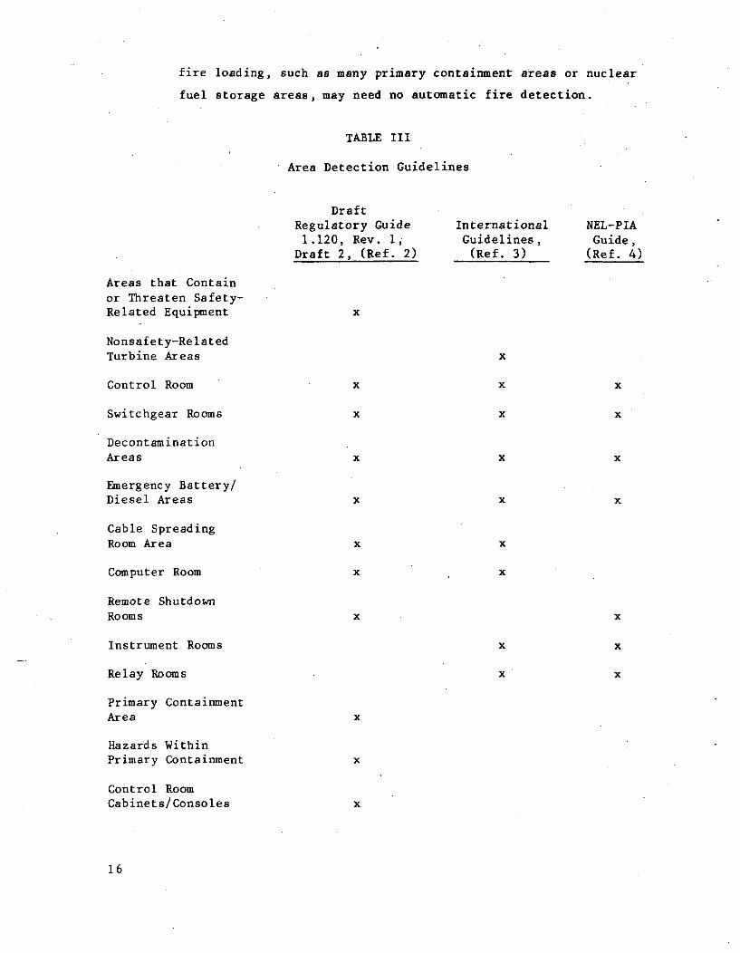
fire loading, such as many primary containment areas or nuclear
fuel storage areas, may need no automatic fire detection.
TABLE III
Area Detection Guidelines
DraftRegulatory Guide International NEL-PIA1.120, Rev. 1, Guidelines, Guide,
Draft 2, (Ref. 2) (Ref. 3) (Ref. 4)
Areas that Containor Threaten Safety-Related Equipment x
Nonsafety-RelatedTurbine Areas x
Control Room x x x
Switchgear Rooms x x x
DecontaminationAreas x x x
Emergency Battery/Diesel Areas x x x
Cable SpreadingRoom Area x x
Computer Room x x
Remote ShutdownRooms x x
Instrument Rooms x x
Relay Rooms x x
Primary ContainmentArea x
Hazards WithinPrimary Containment x
Control RoomCabinets/Consoles x
16
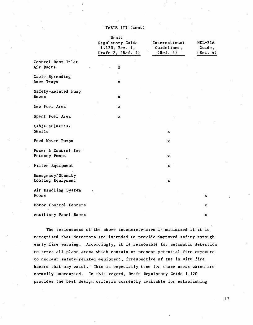
TABLE III (cont)
Dr a ftRegulatory Guide International NEL-PIA1.120, Rev. 1, Guidelines, Guide,
Draft 2, (Ref. 2) (Ref. 3) (Ref. 4)
Control Room InletAir Ducts x
Cable SpreadingRoom Trays x
Safety-Related PumpRooms x
New Fuel Area x
Spent Fuel Area x
Cable Culverts/Shafts x
Feed Water Pumps x
Power & Control forPrimary Pumps x
Filter Equipment x
Emergenc y/StandbyCooling Equipment x
Air Handling SystemRooms x
Motor Control Centers x
Auxiliary Panel Rooms x
The seriousness of the above inconsistencies is minimized if it is
recognized that detectors are intended to provide improved safety through
early fire warning. Accordingly, it is reasonable for automatic detection
to serve all plant areas which contain or present potential fire exposure
to nuclear safety-related equipment, irrespective of the in situ fire
hazard that may exist.' This is especially true for those areas which are
normally unoccupied. In this regard, Draft Regulatory Guide 1.120
provides the best design criteria currently available for establishing
17

safety area detection requirements, when supplemented by the other two
documents for nonsafety plant areas.
2. Design Details and Qualification Tests for Establishing AreaDetection Requirements
In the information sources reviewed for this study, there is
virtually no guidance addressing either the design details or qualifica-
tion tests governing area detection requirements. Except in those in-
stances where the use of certain gaseous suppression techniques call for
automatic detection, even the National Fire Protection Association (NFPA)
codes applying to detectors and nuclear power plant fire protection5 6 are
silent with regard to area detection requirements. Because of this lack
of information, several problems arise regarding the design criteria
discussed in the previous section. Specifically, the following is noted.
(a) The requirement of Draft Regulatory Guide 1.120 to install
detectors in "all areas that present potential fire exposure
to safety-related equipment" causes a problem defining which
areas actually pose a threat to a given safety area. Areas
either immediately adjacent to or separated from a safety area
may or may not present a potential fire exposure, depending on
the level of fire hazard and the adequacy of existing barriers
and suppression systems. An assessment of these factors re-
quires a detailed definition of what constitutes a potential
fire exposure. Without such a definition and a design technique
for determining potential fire exposure, it is difficult to
establish what level of detection coverage actually meets the
design criterion in Draft Regulatory Guide 1.120.
(b) The requirement in Draft Regulatory Guide 1.120 to install
automatic detection inside control room cabinets and along trays
in the cable spreading room lacks confirmatory testing. Because
of this, it has not been proven whether any added benefits are
derived from these special detection measures, although it
can be reasoned that a detector located close to a fire may
prove more effective. Without testing to demonstrate the
18

superior effectiveness of cabinet and tray detectors over area
detectors, it is difficult to justify, in all cases, the cost
and complexity associated with their use. This is especially
true when it is recognized that current qualification testing of
line detectors uses a ceiling configuration, not a cable tray
installation.
B. Selecting Specific Detector Types
Once area detection requirements have been established, it is
necessary to determine what type of detector or combination of detectors
is most suited to the fire hazards found in each area. As explained
earlier, five major types of commercially available detectors have been
considered here because of their proven effectiveness when properly
installed and maintained. The following sections examine how well exist-
ing sources guide in the selection of each detector type and what addi-
tional guidance is needed to help designers make an informed detector
choice.
1. Design Criteria for Selecting Specific Detector Types
None of the nuclear regulatory or insurance agency documents reviewed
for this study 2 - 4 provides definitive design criteria for the selecting
detectors. In Draft Regulatory Guide 1.120 reference is made only to
continuous line heat detectors for cable trays, while the International
Guidelines state simply that, ". . . detectors should be selected
according to the operational and local requirements." Based on this lack
of guidance, more specific design criteria need to be defined. At a
minimum, detector selection criteria should acknowledge the influence of.
the following factors on detector choice.
(a) Combustion Products -- Detectors which prove to be sensitive to
combustion products from test materials (e.g., cellulosic and
liquid flammables) may be insensitive to the combustion products
produced by other materials commonly found in power plants
(e.g., cable insulation). To illustrate, ionization detectors
may not detect large smoke particles, which lack mobility in a
19
static electric field. Similarly, an infrared or ultraviolet
detector may not be able to detect flames through heavy smoke or
through combustion products that may screen the portion of light
spectrum to which the detector is sensitive.
(b) Fire Development -- Because some fires propagate rapidly (e.g.,
oil fires) while others start more slowly (e.g., cable fires),
it would be appropriate to select a detector whose response time
is consistent with the speed of anticipated fire development.
Also, the size to which a fire may be permitted to grow safely
in a particular plant area can influence the appropriateness of
a detector choice. A heat detector may be. the correct choice
for an oil fire but may be too slow to respond to a cable fire.
(c) Ventilation -- In rooms having large ventilation rates, combus-
tion products and heat may be drawn from a room before reaching
the point of triggering heat, photoelectric, or ionization
detectors. To overcome this, line-of-sight area detectors which
do not depend on smoke concentrations for operation or con-
tinuous line local heat detectors which may be located closer to
the fire source should be considered. However, since ventila-
tion rates are often a function of plant operating conditions,
outside temperatures, and ventilation system design, it is
difficult to predict how severely ventilation conditions can
degrade a particular detector's operation and under what circum-
stances line-of-sight or continuous line detectors would be
superior.
(d) Room Congestion -- In rooms containing large amounts of piping,
ductwork, cable trays, and equipment, certain detectors which
depend on line-of-sight "viewing" of a fire (e.g., infrared or
ultraviolet detectors) may be ineffective because a fire may be
blocked from the detector by room congestion.
20
(e) Room Geometry -- Rooms with high ceilings may render heat, photo-
electric, and ionization detectors ineffective because the
buoyant effect of the rising combustion gases may be insuffi-
cient to overcome the ceiling height and may stratify the gases,
especially if ventilation rates are low. In this case, infrared
or ultraviolet detectors may be the best choice.
(f) Operational Activities -- If operational activities produce
signals to which a given detector is sensitive, false alarms may
result. For instance, an infrared or ultraviolet detector may
interpret welding activities as a fire or an ionization detector
may be unable to distinguish combustion products from an operat-
ing diesel from those of a fire.
(g) Maintenance Effect -- The sensitivity of some detectors may
degrade more dramatically with age than that of others. As a
result, frequent maintenance and testing may be required of
certain detectors in order to ensure satisfactory performance.
(h) Cost -- On a relative basis, the costs of detector elements can
be expressed approximately as follows:
i) Heat detectors $ x
ii) Ionization and $ 6xphotoelectric detectors
iii) Infrared detectors $ 6x
iv) Ultraviolet detectors $ 18x
The use of a large number of ultraviolet detectors in areas
where heat detectors are sufficient would be prodigal, unless
the broader area coverage gained through use of ultraviolet
detectors would significantly reduce the total number of
detectors required.
21
The importance of these factors in considering various power plant
detector applications is discussed in the next section.
2. Design Details for Selecting Specific Detector Types
Detailed guidance addressing the selection of detectors, based on the
criteria listed in the previous section, should be available. However, a
review of NFPA codes 5 6 revealed little information useful in determining
which detector types should be selected for specific plant locations.
Only general guidance describing the operating principles of detectors is
presented in the codes. As a result, the selection of a particular
detector must be made by a designer on the basis of operating principles,
rather than on a rigorous application of the criteria previously listed.
In an effort to define more clearly the types of detectors most
suited to different plant areas, a listing was developed of the plant
areas outlined in Table III vis a vis the physical characteristics of each
area as related to fire detector selection. Table IV shows the result of
this effort.
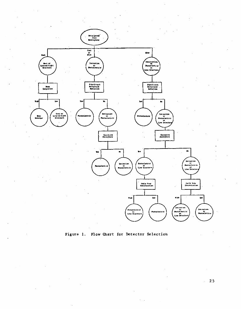
In developing Table IV, a number of judgments were made regarding the
relative importance of each area design characteristic and the relative
rating of conditions within each plant area. Figure 1 summarizes the
logic used in choosing a detector type for each area. From this logic
chart and Table IV, a number of observations can be made. First, in those
situations where either a fast or slow fire may develop, ionization and
photoelectric detectors were chosen over heat detectors because of the
delayed response time of heat detectors to slowly developing fires. Only
in diesel generator rooms, where diesel combustion products may set off
photoelectric or ionization detectors, does the selection of a heat
actuated detector appear suitable. Second, it should be recognized that
the permissible size of a fire from the standpoint of its effect on plant
safety should be considered in the selection of a detection system, in
addition to the anticipated speed of fire development. Because of the
difficulty in defining what constitutes a maximum acceptable fire size,
this factor has been excluded from Figure 1. Third, it may not be
22
possible to quantify what constitutes "significant background radiation,"
a "corrosive atmosphere," a "cable tray concentration," or a "congested
room." Therefore these factors have been only qualitatively considered.
Fourth, in those instances where more than one detector choice is given,
no effort has been made to define where ionization, photoelectric, or line
detectors may be superior. This is because many poorly defined and
misunderstood factors can influence the particular choice. For instance,
as concluded in an earlier Sandia Laboratories fire protection study,
relative detector reliability is understood only in a qualitative manner;
none of the additional literature reviewed for this current report has
revealed any new data to modify this conclusion. In addition to the
reliability factor, other studies 1 6 have concluded that:
(a) the sensitivity of photocells used in detectors may 'drift'
with aging, and
(b) at 'small' distances from a fire, ion chamber detectors are.
more sensitive than photoelectric devices, while at 'large'
distances the situation is reversed.
These examples of subtle differences among detectors demonstrate the
difficulty in developing Table IV and Figure 1 much beyond the point shown
in this report, and, as will be seen inf the next section, detector qualifi-
cation test procedures fall short of answering many of the more important
questions influencing detector selection.
3. Qualification Tests for Selecting Specific Detector Types
The qualification test standards currently being used by Underwriters
Laboratories (UL) for nonresidential detector applications are:
UL 167 - 'Smoke Detectors, Combustion Products Type'
UL 168 - 'Smoke Detectors, Photoelectric Type'
UL 521 - 'Fire Detection Thermostats'
23

TAIILE IV
Physical Characteristics of Selected Safety-Related Plant Areasas Related to Detector Selection
Plant Areas
Control Room
Cable SpreadingRoom
Switchgear Rooms
DecontaminationAreas
Batery Rooms
Diesel Rooms
Computer Rooms
Safety PumpRooms
Nuclear FuelAreas
PrimaryCo•,•air. eat
Relay Rooms
RemoteShutdown Rooms
Instrument Rooms
Other =ectricalEquipment Areas
PredominantCombustibles
Cable Insulation
Cable Insulation
Cable Insulation
Plastic.i. Cloth,-Cable Insulation
Hydrogen GasCable Insulation
Lube OilDiesel Fuel OilCable Insulation
Plastics, PaperCable Insulation
Cable InsulationLube Oil
PlasticsCable Tnsulation
Cable Insulation
Lube Oil
Cable insulation
Cable 1nsulation
Cable Insulation
Cable Insulation
Anticipated (a) Room Congestion (b) Room (d)Fire Development 'for Detection Ceiling Height
Slow
Slow
Initially Fast -High Voltage ShortSlow - Propagation
Fast or Slow
Explosive or Slow
Fast or Slow
Fast or Slow
Fast or Slow
Fast or Slow
Fast or Slow
Slow
Slow
Slow
Slow
Low
High
Low
Variable (c)
Low
Low
Low
Low
Variable
Medium
High
Medium
iHigh
Variable
Low
Low
Medium
Variable (W)
Low
High
Low
Variable
High
Variable
Medium
Variable
Medium
Variable
Other Factors
False CeilingsContinuously Marned
Nune
Htigh TemperaturePotential
Transient FireLoads. BackgroundRadiation
CorrosiveAtmosphere
Diesel CombustionProducts
False Ceilings &False Floors
None
Transient FireLoads. BackgroundRtdiation
BackgroundRadiation
None
None
Suitable Detector Choice
Ionization or Photoelectric
Ionization or Photoelectricor Line Type
Ionization or Photoelectric
Photoelectric
Photoelectric (plus hydrogensensor or ventilation)
Heat - Rate of Rise orUltraviolet or Infrared
Ionization or Photoelectric
Ionization or Photoelectric
Photoelectric
Photoelectric
Ionization or Photoelectric
Ionization or Photoelectric
Ionization or Photoelectric
Ionization or Photoelectric
None
None
(a) Based on cable burning tests performed at Sandia Laboratories (References 7 and 8) cable fires, involving IEEZ - 383 approved cables. develop slowly.in the time span of mirnute&. In this table, fires, such as oil which can fully develop in time spans of seconds, were rated as "fast".
(b) The influence of room congestion on detector selection is a factor only in those cases where line-of-sight detectors are satisfactory from the standpoint
of all other characteristics being considered.
(cW "Var-table" refers to those situations in which there are either transient fire conditions within an area or significant variations of physical characteristics
between different power pLnts.
(dW The terms low, medium, an d high ceilings were arbitrarily chosen as rooms having real or false ceilings: low, less than 10 feet high; medium, 10 to 30
feet high; high, greater th.n 30 feet high.
tit
Figure 1. Flow Chart for Detector Selection
25

In addition to these standards, another standard, UL 268-"Smoke
Detectors for Fire Protective Signaling Systems," is being developed to
combine UL Standards 167 and 168. A review of a proposed version of UL
268 has revealed, however, that many of the deficiencies to .be discussed
later, which are inherent in UL 167 and 168 for nuclear power plant fire
detection, still exist in the new standard, although some improvements
have been attempted by utilizing several air flow rates in one test
Sequence and by subjecting detectors to a smoldering fire condition in
another test. Unfortunately, the varied air flows in UL 268 are used only
in a test for checking false alarming and sensitivity to gray smoke pro-
duced by a cotton wick, while the smoldering fire test uses smoke from
wood heated on a hotplate. Neither of these conditions is typical of
nuclear power plant combustibles.
In terms of the detectors considered in this study, no published UL
standard covers ultraviolet or infrared detectors, while UL 167, UL 168,
and UL 521 address ionization, photoelectric, and area and line heat
detectors. Each of these test standards contains a wide range of construc-
tion and performance tests to establish detector sensitivity, reliability,
safety, and overall quality; once a detector has passed all applicable UL
tests, it then may be marketed as a "UL Listed" detector.
Because UL listed detectors are installed in a variety of industrial
locations, UL test procedures are generic in nature and may not be appli-
cable to some nuclear power plant situations. Examples of this include
the following:
(a) UL Standard 167 for ionization detectors subiects the detectors
to combustion products from paper, polystyrene, gasoline, wood,
and cotton, while UL 168 for photoelectric detectors uses paper,
polystyrene, gasoline, wood, punk, and kerosene. Neither of
these standards tests detectors with cable insulations, lube
oils, diesel oils, or plastics commonly found in nuclear plants.
(b) None of the UL standards for smoke or heat detectors permits an
evaluation of detector response times as a function of smoke and
26
heat release rates. This is because the UL tests subject dif-
ferent detector types to different combustibles. In addition to
paper, gasoline, wood, and polystyrene tests, which are common
to UL 167 and 168, other tests involving cotton in UL 167, punk
and kerosene in UL 168, and alcohol in UL 521 are also per-
formed. No correlation is made among these latter tests and a
cable insulation test.
(c) From the standpoint of detector location and spacing, discussed
more thoroughly in Section III.C of this report, none of the UL
detector tests measures the effect of area ventilation rates on
detector performance under fire conditions. Only in the UL 167
cotton test for ionization detectors and the UL 168 punk and
kerosene tests for photoelectric detectors has there been an
attempt to determine the influence of smoke movement on detector
sensitivity. Unfortunately, these tests are conducted in a
smoke chamber apparatus, not in a room, and the smoke velocities
used in these tests are only 30 to 35 feet per minute (1.6 to
1.9 m/sec)--well below ventilation velocities found in some13
power plant areas.
(d) For testing detectors in a room environment, all of the UL stan-
dards use rooms having a smooth ceiling, with no physical
obstructions between the fire source and detectors, and with air
movement not exceeding 10 feet per minute (0.5 m/sec). As a
result, the influence of room congestion typically found in
power plants is not measured.
(e) UL standards 167 and 168 call for test rooms approximately 12
feet (3.65 m) high, while UL 521 specifies a 15-foot (4.57 m)
ceiling. Without testing each type of detector at several
higher ceiling heights, it is difficult to assess how well a UL
listed detector will perform in high bay areas of a power plant.
(f) From the standpoint of operational and maintenance considera-
tions, the UL detector st-andards are basically complete. Each
27

standard calls for corrosion tests, humidity tests, and vibra-
tion tests. In addition, other tests applying only to ioniza-
tion and photoelectric detectors, include static discharge,
paint loading, and dust accumulation tests. For a nuclear
plant, only the effects of radiation, diesel combustion prod-
ucts, different corrosive atmospheres, and other interferences
are needed to supplement the UL tests.
Based on the above comments, it is apparent that without some addi-
tional qualification testing, the indiscriminate installation of UL listed
detectors may not, in itself, assure satisfactory detector performance.
Because of this uncertainty, at least one other detector study has recom-
mended a new qualification test method.1 7 This new procedure calls for
all types of detectors to be tested using the same set of conditions. As
proposed, the testing would include fifteen different tests made up of
three fire sizes for each of five combustibles. To represent a broad
spectrum of fire types and detector sensitivities, the fire test combus-
tibles would include a flaming cellulosic, a smoldering cellulosic, a
flaming plastic, a smoky oil, and a nonsmoky alcohol, while each of the
three fire sizes would be about twice the size of the next smaller fire
with the smallest fire for each combustible being selected to assess a
detector's maximum sensitivity. Unfortunately, even this new method is
susceptible to some of the shortcomings of current procedures, including
the use of ceiling heights, ventilation conditions, and some combustibles
not common to nuclear power plants.
C. Locating and Spacing Detectors
Once plant areas requiring fire detection have been established, and
appropriate detector types chosen, it is necessary to locate and space the
detectors in a manner consistent with (1) the environment in which the
detector must function and (2) the qualification standard to which the
detector was tested. The following sections examine how well existing
information sources guide the locating and spacing of detectors and what
additional guidance is needed to help designers.
28
1. Design Criteria for Locating and Spacing Detectors
None of the nuclear regulatory or insurance agency documents reviewed
for this study 2 - 4 provides definitive design criteria for locating and
spacing detectors. Only through reference to NFPA 72 E, "Standard for
Automatic Fire Detectors"' 5 does Draft Regulatory Guide 1.120 acknowledge
the influence of location and spacing on detector performance. As a
result of this lack of guidance, more specific design criteria need to be
defined to take into account the factors listed below, some of which have
been assessed in terms of their influence on detector selection (Section
Iii. .B).
(a) Ventilation -- Bulk air flow through a room or local air flow in
the vicinity of ventilation ductwork can dilute combustion prod-
ucts or prevent the products from reaching a detector. Proper
detector positioning must balance the effects of bulk air flow
through a room against dilution near return air duct openings.
(b) Ceiling Height -- Stratification of combustion products below
the ceiling can delay the response of a heat or smoke detector
until a fire has grown to dangerous proportions. Before a detec-
tor can be effectively installed, the anticipated stratification
in a room must be determined as a function of the floor-to-
ceiling combustion product buoyancy gradient under various
permissible fire sizes, room ventilation rates, and outside
temperature conditions.
(c) Ceiling Construction -- Solid ceiling joists and beams or sloped
ceilings can cause stagnant air pockets which prevent combustion
products from spreading uniformly. Under these conditions,
combustion products may need to spill over from one stagnant
zone to another before detection can be accomplished, thereby
delaying detector response.
(d) Room Congestion -- Ductwork, piping, and cable trays can deflect
combustion products away from a detector, especially if
29

ventilation conditions for detection are already unfavorable.
Significant congestion may dictate the installation of detectors
away from the ceiling and closer to those fire hazards requiring
maximum protection.
(e) Zoning -- To minimize the possibility of unintentionally actuat-
ing an automatic suppression system, some form of detection
zoning, requiring the operation of more than one detector before
automatic suppression starts, may be useful. The type and
degree of zoning selected, however, should consider the benefits
of reduced false alarms versus the risk of delayed detection
system response under actual fire conditions.
The importance each of the above factors plays in power plant applica-
tions and the level of design guidance available for each factor are
discussed in the next section.
2. Design Details for Locating and Spacing Detectors
A detector can function properly only if the fire properties to which
it is sensitive (e.g., heat, smoke, flame, or combustion products) are
able to reach the detector. This has been recognized for many years and
much of the design guidance developed for detectors in NFPA Standard 72E5
has addressed location and spacing. Unfortunately, little of the avail-
able design guidance goes beyond a qualitative assessment of the criteria
listed in Section III.C.I. Even in those instances where quantitative
direction is given, there appears to be a lack of supporting experience or
test data.
Table V compares the design guidance in NFPA 72E with criteria govern-
ing the location and spacing of detectors. A review of Table V shows a
number of design uncertainties applying to each locating and spacing
design criterion. The significance of these uncertainties is discussed
more thoroughly in the following paragraphs.
30

TABLE V •
Comparison of Detector Location and Spacing Criteria with GoverningDesign Guidance Quoted from NFPA 72E
AREA HEAT DETECTORS
Des•en Criteria
(a) Ventilation
NFPA 72EDesign Guidance
NFPA 72EParagraphReference Comments
None None Guidance needed
(b) Ceiling Height Generally, height is the most importantsingle dimension where ceiling heightsexceed 16 feet.
As smoke and heat rise from a fire. theytend to spread in the general form of aninverted cone. As the ceiling height in-creases, a larger size fire is requiredto actuate the same detector in the sametime. In view of this, it is mandatorythat the designer of a fire detection systemcalling for heat detectors consider the size ofthe fire, and rate of heat release, which maybe permitted to develop before detection isultimately obtained.
The most sensitive detectors should beemployed which are suitable for themaximum ambient temperature at heightsabove 30 feet.
Spot-type heat detectors shall be locatedupon the ceiling not less than 6 inchesfrom the side wall, or on the side wallsbetween 6 inches and 12 inches from theceiling.
Spacing
Irregular Areas. For irregular shapedareas the spacing between detectors maybe greater than the listed spacing, pro-vided the maximum spacing from a detectorto the furthest point of a side wall orcorner within its zone of protection isnot, greater than 0.7 times the listed spacing.
Open Joist Construction. The spacing ofspot-type heat detectors installed on ajoisted ceiling shall not exceed 50 percent oftheir listed spacing when measured at rightangles to the solid joists.
B-1. 2 thruB-1. 5
I. Ventilation interaction ignored
ii. Manner of considering fire size andrate of heat release unclear
lL The basis for 16 feet (4.9 m) and30 feet (9. 1 rr,) is undocumented andapparently unrelated to the UL testheights of 12 feet (3. 6 m) for smokedetectors and 15 feet (4.5 m) for heatdetectors (See Section III. B. 3)
(c) CeilingConstruction
3-4.1, 3-5 I. S-uitability of 6 and 12 inch (0.15 and0.3 m) distances not confirmed by ULtests
ii. The 50% of listed detector spacing forpartitions near smooth ceilings or openjoist ceilings is not confirmed by ULdetector tests
III. A beam depth of 4 inches (0.1 m) fora "smooth" ceiling may be excessive(Reference 14)
iv. The guidance for sloped ceilings Is notconfirmed by UL detector tests 167.168. or 521
W..H
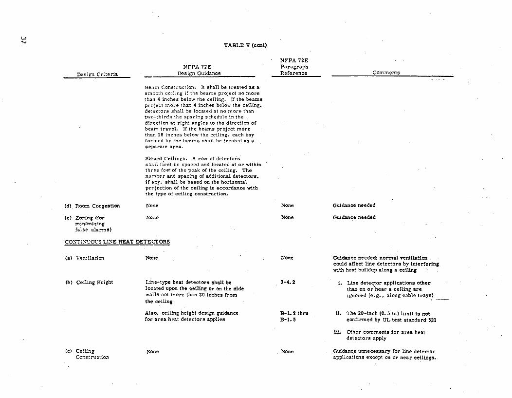
TABLE V (cont)
DeEign Crit*eriaNFPA 72E
Design Guidance
Beam Construction. It shall be treated as asmooth ceiling if the beams project no morethan 4 inches below the ceiling. If the beamsprcject more than 4 inches below the ceiling,detectors shall be located at no more thantwo-thirds the spacing schedule in thedirection at right angles to the direction ofbeam travel. If the beams project morethan 18 inches below the ceiling, each bayformed by the beams shall be treated as aseparate area.
Sloped Ceilings. A row of detectorsshE.ll first be spaced and located at or withinthree feet of the peak of the ceiling. Thenumber and spacing of additional detectors,if any, shall be based on the horizontalprojection of the ceiling in accordance withthe type of ceiling construction.
NFPA 72EParagraphReference Comments
(d) Room Congestion
(e) Zordng (formlnmrnlzingfalse alarms)
None
None
None
None
Guidance needed
Guidance needed
CO.XTN-%OQtS LINE REAT DETECTORS
(a) Ventilation
(b) Ceiling Height
None None
i.ne-type heat detectors shall belocated upon the ceiling or on the sidewalls not more than 20 inches from
the ceiling
Also, ceiling height design guidancefor area heat detectors applies
3-4.2
Guidance needed; normal ventilationcould affect line detectors by interferingwith heat buildup along a ceiling
1. Line detector applications otherthan on or near a ceiling areignored (e. g.. along cable trays)
ii. The 20-inch (0. 5 m) limit Is notconfirmed by UL test standard 521
Iii. Other comments for area heatdetectors apply
Guidance unnecessary for line detectorapplications except on or near ceilings.
B-i. 2 thruB-1. 5
Cc) CeilingConstruction
None o None

TABLE V (cort)
CONTINUOUS LINE HEAT DETECTORS
NFPA 72EDesign Guidance
NFPA 72EParagraphReferenceDes=. Criteria
Md) Room Congestion
(e) Zodr.4g (forr.inL-nizingfaise alarms)
None
None
None
None
Comments
Guidance needed; high temperature spotsresulting from normal operation of congestedequipment could actuate a local line detector
Guidance needed
IONIZATION AND PHOTOELECTRIC DETECTORS
(a) Ventilation
(b) Ceiling Height
(c) CeilingConst ruction
Spacing of smoke detectors shallresult from an evaluation basedupon engineering judgmentsupplemented, if feasible, by fieldtests. Ceiling shape and surfaces,ceiling height, configuration ofcontents. burning characteristics ofthe stored combustibles, andver.:ila*ion are some of the parametersthat shall be considered.
Stratification occurs when the tempera-ture of the smoke particles as generated.usually from a smolddring or small fire,reach the temperature of the surroundingair. Since it has lost the thermal lift,the smoke stops rising and stratifies.For proper protection for buildings withhigh ceilings, detectors shall be installedalternately at two levels; one half at ceilinglevel, and the other half at least three feetbelow the ceiling.
Joisted Ceilings. Ceiling obstructions8 inches or less in depth shall be con-sidered equivalent to a smooth ceiling inview of the "spill over" efrect of smoke.
Slope Ceilings (Peaked or Shed-Type).A row of detectors shall first be spacedand located within 3 feet of the peak measuredhorizontally. The number and spacing ofadditional detectors, if any, shall be based onthe horizontal projection of the ceiling.
4-4.1
4-4.5.1.4-4.5.2
4-4.3,4-4.4v4-4.6
Guidance inadequate
i. Stratification from hot air heating systemshas been ignored
ii. The term "high ceilings" is not definedquantitatively
ill. The effectiveness of two level detectorsseparated by three feet (0. 9 m) isquestionable for all "high ceilings" foundin power plants
1. None of the distances for ceiling constructionor detector location are confirmed suitably byUL tests
ii. The recommendations of manufacturers forsmooth ceilings are not independently testedfor validity by an impartial testing laboratory

TABLE V (cat)
Des!en Cr:teriaNFPA 72E
Design Guidance
Beam Construction. Beams 8 inches or lessin depth can be considered equivalent to asmooth ceiling in view of the "spill over" effectof smoke. In beam construction over 8 inchesin depth, movement of heated air and smokemay be slowed by the pocket or bay formed bythe beams. In this case, spacing shall bereduced. If the beams exceed 18 inches indepth and are more than 8 feet on centers.each bay shall be treated as a separate arearequiring at least one detector.
NFPA 72EParagraphReference Comments
(d) Room Congestiom
(e) Zoning (formini-izlngfalse alarms)
None None
4-5.1
Guidance needed
Guidance neededThe selection and installation of smokedetectors shall take into considerationboth the design characteristics of thedetector and the areas into which thedetectors will be installed so as to preventfalse operation or nonoperation afterinstallation. Some of the considerationsare as follows:
1. Smoke detectors having a fixed temp-erature element as part of the unit shallbe selected in accordance with the maxi-mum ceiling temperature that can beexpected in service.2. The installation shall take into
consideration the maximrnum ambientsmoke density resulting from manufacturingprccesses or other sources.
3. Since the projected beam-type unit willoperate when the light-path to the receiveris interrupted or obscured; the light-pathshall be kept clear of opaque obstacles atall times.
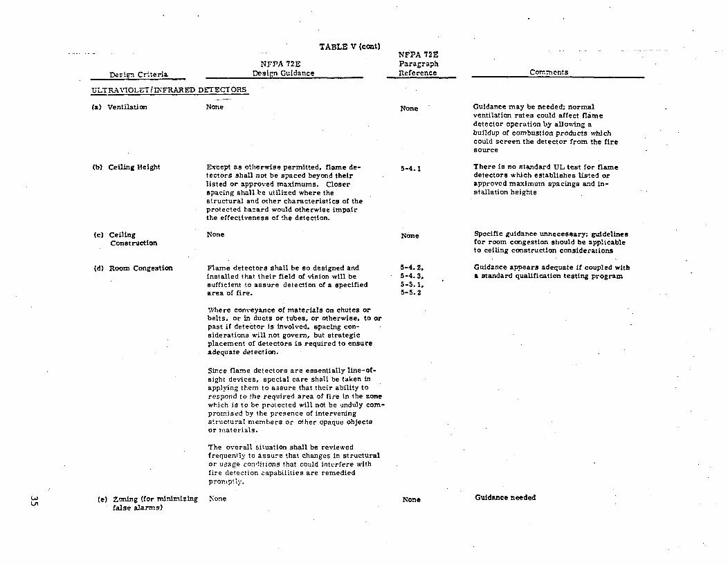
TABLE V (cOMt)
NFPA 72EDesign Guidance
NFPA 72EParagraphReferenceDesign Criteria
ULTRAVIOLET IUIFRARED DETECTORS
(a) Ventilation None None
Comments
Guidance may be needed; normalventilation rates could affect flamedetector operation by allowing abuildup of combustion products whichcould screen the detector from the firesource
There is no standard UL test for flamedetectors which establishes listed orapproved maximum spacings and in-stallation heights
(b) Ceiling Height Except as otherwise permitted, flame de-tectors shall not be spaced beyond theirlisted or approved maximums. Closerspacing shall be utilized where thestructural and other characteristics of theprotected hazard would otherwise impairthe effectiveness of the detection.
5-4.1
(c) CeilingConstruction
(d) Room Congestion
None None
5-4.2,5-4.3,5-5.1,5-5.2
Specific guidance unnecessary; guidelinesfor room congestion should be applicableto ceiling construction considerations
Guidance appears adequate if coupled witha standard qualification testing program
Flame detectors shall be so designed andinstalled that their field of vision will besufficient to assure detection of a specifiedarea of fire.
Where conveyance of materials on chutes orbelts, or in ducts or tubes, or otherwise, to orpast if detector is involved, spacing con-siderations will not govern, but strategicplacement of detectors is required to ensureadequate detection.
Since flame detectors are essentially line-of-sight devices, special care shall be taken inapplying them to assure that their ability torespond to the required area of fire in the zonewhich is to be protected will not be unduly com-promised by the presence of interveningstructural members or o.her opaque objectsor materials.
The overall situation shall be reviewedfrequently to assure that changes in structuralor usage conditions that could interfere withfire detection capabilities are remediedpromptly.
LI) (e) Zoning (for minimizingfalse alarms)
None None Guidance needed
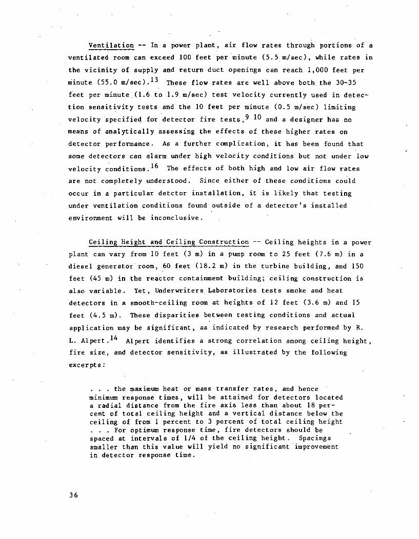
Ventilation -- In a power plant, air flow rates through portions of a
ventilated room can exceed 100 feet per minute (5.5 m/sec), while rates in
the vicinity of supply and return duct openings can reach 1,000 feet per
minute (55.0 m/sec). 1 3 These flow rates are well above boththe 30-35
feet per minute.(1.6 to 1.9 m/sec) test velocity currently used in detec-
tion sensitivity tests and the 10 feet per minute (0.5 m/sec) limiting
velocity specified for detector fire tests, 9 10 and a designer has no
means of analytically assessing the effects of these higher rates on
detector performance. As a further complication, it has been found that
some detectors can alarm under high velocity conditions but not under low
velocity conditions.16 The effects of both high and low air flow rates
are not completely understood. Since either of these conditions could
occur in a particular detctor installation, it is likely that testing
under ventilation conditions found outside of a detector's installed
environment will be inconclusive.
Ceiling Height and Ceiling Construction -- Ceiling heights in a power
plant can vary from 10 feet (3 m) in a pump room to 25 feet (7.6 m) in a
diesel generator room, 60 feet (18.2 m) in the turbine building, and 150
feet (45 m) in the reactor containment building; ceiling construction is
also variable. Yet, Underwriters Laboratories tests smoke and heat
detectors in a smooth-ceiling room at heights of 12 feet (3.6 m) and 15
feet (4.5 m). These disparities between testing conditions and actual
application may be significant, as indicated by research performed by R.
L. Alpert.14 Alpert identifies a strong correlation among ceiling height,
fire size, and detector sensitivity, as illustrated by the following
excerpts:
the maximum heat or mass transfer rates, and henceminimum response times, will be attained for detectors locateda radial distance from the fire axis less than about 18 per-cent of total ceiling height and a vertical distance below theceiling of from 1 percent to 3 percent of total ceiling height
For optimum response time, fire detectors should bespaced at intervals of 1/4 of the ceiling height. Spacingssmaller than this value will yield no significant improvementin detector response time.
36
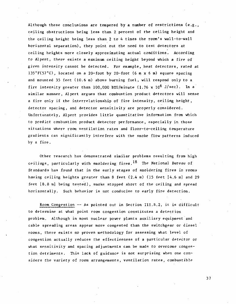
Although these conclusions are tempered by a number of restrictions (e.g.,
ceiling obstructions being less than 2 percent of the ceiling height and
the ceiling height being less than 2 to 4 times the room's wall-to-wall
horizontal separation), they point out the need to test detectors at
ceiling heights more closely approximating actual conditions. According
to Alpert, there exists a maximum ceiling height beyond which a fire of
given intensity cannot be detected. For example, heat detectors, rated at
135°F(57°C), located on a 20-foot by 20-foot (6 m x 6 m) square spacing
and mounted 35 feet (10.6 m) above burning fuel, will respond only to a
fire intensity greater than 100,000 BTU/minute (1.76 x i06 J/sec). In a
similar manner, Alpert argues that combustion product detectors will sense
a fire only if the interrelationship of fire intensity, ceiling height,
detector spacing, and detector sensitivity are properly considered.
Unfortunately, Alpert provides little quantitative information from which
to predict combustion product detector performance, especially in those
situations where room ventilation rates and floor-to-ceiling temperature
gradients can significantly interfere with the smoke flow patterns induced
by a fire.
Other research has demonstrated similar problems resulting from high
ceilings, particularly with smoldering fires. 1 8 The National Bureau of
Standards has found that in the early stages of smoldering fires in rooms
having ceiling heights greater than 8 feet (2.4 m) (15 feet [4.6 m] and 29
feet [8.8 m] being tested), smoke stopped short of the ceiling and spread
horizontally. Such behavior is not conducive to early fire detection.
Room Congestion -- As pointed out in Section III.B.2, it is difficult
to determine at what point room congestion constitutes a detection
problem. Although in most nuclear power plants auxiliary equipment and
cable spreading areas appear more congested than the switchgear or diesel
rooms, there exists no proven methodology for assessing what level of
congestion actually reduces the effectiveness of a particular detector or
what sensitivity and spacing adjustments can be made to overcome conges-
tion detriments. This lack of guidance is not surprising when one con-
siders the variety of room arrangements, ventilation rates, combustible
37
materials, burn rates, and room geometries that would need to be corre-
lated with levels of room congestion.
Zoning -- Current detector zoning techniques for minimizing the inci-
dence of false alarms or false actuation of extinguishing systems typical-
ly require two or more adjacent detectors to sense a fire and alarm. Al-
though this approach successfully reduces false alarms, it can also reduce
the overall effectiveness of a detection system to below the level at
which the individual detectors originally were tested. For two detectors
to respond in the same manner as one detector, adjustments must be made
in the spacing, sensitivity, and reliability of the two-detector scheme.
Designers currently have no guidance for making these adjustments.
3. Qualification Tests for Locating and Spacing Detectors
The following paragraphs, quoted from the Underwriters Laboratories
Fire Protection Equipment List, 2 0 describe the locating and spacing condi-
tions under which detectors are qualified, together with UL recommuenda-
tions for adapting test results to actual installation conditions.
(a) Area and Continuous Line Heat Detectors
The spacings specified are for flat, smooth ceiling con-struction of ordinary height, generally regarded as themost favorable condition for distribution of heated aircurrents resulting from a fire. Under other forms ofceiling construction reduced spacing of thermostats maybe required. The fire tests conducted to determine thesuitability of the thermostat spacings are conducted ina 60 by 60 ft room having a 15 ft 9 in.* high smooth ceil-ing and minimum air movement. The test fire (denaturedalcohol) is located approximately 3 ft above the floorand of a magnitude so that sprinkler operation is obtainedin approximately two minutes.
*It should be noted that a discrepancy exists between the 15 foot-9-
inch (4.8 m) test ceiling height quoted for photoelectric and ionizationdetectorg Td the 12-foot (3.6 m) height called for in UL Standards 167and 168.
38
S.. The placement and spacing of thermostatic devicesshould be based on consideration of the ceiling construc-tion, ceiling height, room or space areas, space subdivi-sions, the normal room temperature, possible exposure ofthe devices to abnormal heat such as may be produced bymanufacturing processes or equipment, and to draft condi-tions likely to be encountered at the time of a fire.Authorities having jurisdiction should be consulted in allcases before installation.
(b) Ionization Detectors
Spacings - Although no specific spacings are being allocatedto these detectors, the test fire spacings of 30 ft may beused, if practicable, only as a GUIDE or starting point ina detector installation layout. IMPORTANT: THE TEST FIRESCONDUCTED BY THE LABORATORIES ARE BASED ON ONLY ONE SET OFCONDITIONS, NAMELY A 15 FT 9 IN. HIGH SMOOTH CEILING, NOAIR MOVEMENT, AND NO PHYSICAL OBSTRUCTIONS BETWEEN THE FIRESOURCE AND DETECTOR. It should be realized that these arefairly ideal conditions for a symmetrical detector layout.For conditions other than above it is mandatory thatengineering judgment be applied regarding detector loca-tion and spacing. In all likelihood closer spacings andirregular distribution would be required for those instal-lations containin- high stockpiles, higher than 16 ft highceilings, small bays and other ceiling obstructions, andparticularly in areas where there is rapid air movementfrom air conditioning and ventilating systems. The aircurrent patterns should be checked by test smoke or lighttissue paper to determine proper location of detectors.
(c) Photoelectric Detectors
Guidance similar to that provided for ionization detectors
appears to apply to photoelectric detectors, even though the UL
listing does not restate the information.
(d) Ultraviolet/Infrared Detectors
The location of flame detectors should be based on anengineering survey of the conditions to be anticipated inservice and the principle of operation. Detectors should beinstalled only after a thorough study has been made of thearea or premises to be protected (whether in planning or con-struction state) and of the life and property values involved.Prior to engineering a layout of an installation, a copy ofthe manufacturer's technical bulletin should be obtained andreviewed to determine recommended detector locations.
39
Consideration should be given to all features which couldhave a bearing on the location and sensitivity of the detec-tors, including such pertinent factors as coverage in parti-tioned sections, ceiling heights, overlapping of areas of conecoverage to provide maximum protection. Test flames shouldbe employed to check proper detector location.
It is apparent from the above statements that the ideal conditions of
detector test are recognized, but the guidance provided for adapting
qualified detectors to nontest conditions is vague, with considerable
reliance placedupon "engineering judgment" and installation testing.
D. Performing Installation Tests and Maintenance
Because detector installations seldom resemble the controlled condi-
tions of a qualification test and because environmental conditions can de-
grade the original performance of some detectors, in-place testing should
be performed following installation and at regular intervals throughout a
detector's design life. These activities are of major importance in con-
firming the adequacy and continued reliability *of a detection system,
especially in light of the marginal design information and qualification
testing alluded to in earlier sections of this report. The following
sections examine how well existing information sources guide the installa-
*tion testing and maintenance of detectors and what additional guidance is
needed to help design and operations personnel perform these activities.
1. Design Criteria for Performing Installation Tests and Maintenance
The quality assurance section of Draft Regulatory Guide 1.120 pro-
vides the following limited criterion for performing fire protection
system testi.ng:
A test should be established and implemented to ensure thattesting is performed. and verified by inspection and audit todemonstrate conformance with design and system readinessrequirements.
To supplement this criterion, the Standard Technical Specifications,
issued by the NRC for nuclear power plant fire protection, states that:
40

Each fire detection instrument shall be demonstrated operableby performance of the manufacturer's recommended tests atleast once per 6 months.
In addition to these NRC documents, other sources of criteria include the
International Guidelines for Fire Protection3 and a Nuclear Energy
Liability-Property Insurance Association bulletin. 1 5 These sources simply
state that:
The protective measures against the fire hazards should beperiodically checked for their efficiency.
and
Detectors should be properly maintained by qualified personsin accordance with manufacturer's recomnendations. As aminimum, annual cleaning, sensitivity adjustment, andoperational testing should be performed.
From the above statements, it is clear that the testing and main-
tenance criteria available in regulatory and insurance documents can
easily be expanded into a more definitive list of criteria. Such a list,
presented below, was gleaned from a number of sources, including the NFPA
Standard on Automatic Fire Detectors 5 and the Underwriters Laboratories
Fire Protection Equipment List and associated standards. 9 -11 20
(a) Installation Test Criteria
* A visual inspection of all detectors should be made to
ensure that detectors are installed according to design
specifications.
" Each detector should be checked to confirm proper wiring
and power connections.
* The stability of the detection system should be monitored
for several weeks prior to activation of the central fire
alarm system to identify potential sources of false alarms,
such as background radiation or combustion products.
41
* The response of the detection systems should be confirmed
using a test fire under environmental conditions antici-
pated to occur normally in the area being protected. The
test fire should produce the type and degree of flame,
heat, smoke,. and combustion products characteristic of com-
bustibles found in the protected area. The environmental
test conditions should be representative of the tempera-
tures and ventilation rates expected normally to occur.
(b) Maintenance Criteria
* Detectors should be periodically tested in place to
confirm continued satisfactory operation.
* Detectors should be periodically cleaned to remove
accumulated dust and dirt. The frequency of cleaning
will depend on the type of detector involved and the pre-
vailing environmental conditions.
* Following periodic testing or cleaning, detectors should
be restored to service promptly.
It is apparent that a designer needs additional guidance before even
these abbreviated testing and maintenance requirements can be implemented.
This additional guidance, which is needed to define maintenance intervals,
inspection techniques, required training, and calibration standards, tradi-
tionally has come from either detector manufacturers or what is termed in
fire protection literature as "the authority having jurisdiction." The
next section of this report addresses the adequacy of the traditional
testing and maintenance design details available with respect to nuclear
power plant applications.
2. Design Details for Performing Installation Tests and Maintenance
Performing installation tests and maintenance in accordance with the
recommendations of a detector manufacturer has both advantages and
42
disadvantages for a nuclear power plant. Table VI lists some of the more
important concerns in this regard.
It can be seen from Table VI that, although detector manufacturers
have the potential for providing the most comprehensive guidance for
testing and maintaining detector systems, there is little commercial
incentive for a manufacturer to research the special problems of nuclear
power plant fire detection. Based on this, it is questionable whether the
testing and maintenance programs recommended by manufacturers are entirely
suitable for power plant applications. Furthermore, since design
guidelines such as NFPA Standard 72E, 5 defer much of their authority to
"manufacturer's recommendations," there is no standard to which a designer
can turn for either absolute or relative evaluation of the performance of
an installed detection system. Such a standard appears to be needed for
nuclear power plant detection systems.
3. Qualification Tests for Performing Installation Tests and Maintenance
At present, there are no uniformly applied qualification tests for
confirming the in-place response characteristics and maintenance require-
ments of detectors. Although UL standards subject detectors to a variety
of corrosion, vibration, humidity, temperature, and dust accumulation
conditions, the UL test results are judged as either pass or not pass,
with no extension of the qualification tests to developing in-service
maintenance procedures or test intervals. In addition, no part of the UL
standards identifies what minimum installation tests a UL-listed detector
should undergo to confirm performance after installation. Such installa-
tion tests should be conducted, although the development and implementa-
tionof the tests-may be beyond the purview of Underwriters Laboratories
and may need to be the subject of a future independent research effort.
In the interim, however, it is important to identify what course of action
should be followed to assure dependable detector operation in a nuclear
power plant. The conclusions and recommendations sections of this report
which follow attempt to identify and justify a proper course of action.
43
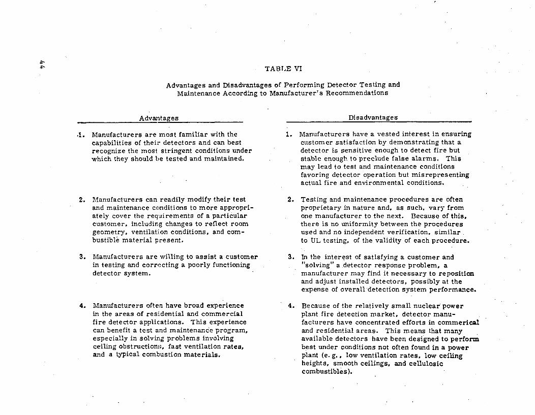
TABLE VI
Advantages and Disadvantages of Performing Detector Testing andMaintenance According to Manufacturer's Recommendations
Advantages
41. Manufacturers are most familiar with thecapabilities of their detectors and can bestrecognize the most stringent conditions underwhich they should be tested and maintained.
2. Manufacturers can readily modify their testand maintenance conditions to more appropri-ately cover the requirements of a particularcustomer, including changes to reflect roomgeometry, ventilation conditions, and com-bustible material present.
3. Manufacturers are willing to assist a customerin testing and correcting a poorly functioningdetector system.
4. Manufacturers often have broad experiencein the areas of residential and commercialfire detector applications. This experiencecan benefit a test and maintenance program,especially in solving problems involvingceiling obstructions, fast ventilation rates,and a typical combustion materials.
Disadvantages
1. Manufacturers have a vested interest in ensuringcustomer satisfaction by demonstrating that adetector is sensitive enough to detect fire butstable enough to preclude false alarms. Thismay lead to test and maintenance conditionsfavoring detector operation but misrepresentingactual fire and environmental conditions.
2. Testing and maintenance procedures are oftenproprietary in nature and, as such, vary fromone manufacturer to the next. Because of this,there is no uniformity between the proceduresused and no independent verification, similarto UL testing, of the validity of each procedure.
3. In the interest of satisfying a customer and"solving" a detector response problem, amanufacturer may find it necessary to repositionand adjust installed detectors, possibly at theexpense of overall detection system performance.
4. Because of the relatively small nuclear powerplant fire detection market, detector manu-facturers have concentrated efforts in commericaland residential areas. This means that manyavailable detectors have been designed to performbest under conditions not often found in a powerplant (e. g., low ventilation rates, low ceilingheights, smooth ceilings, and cellulosiccombustibles).

IV. CONCLUSIONS
This report examined the adequacy of fire detection in the context of
nuclear power plant safety. Topics considered were (1) establishing area
detection requirements, (2) selecting specific detector types, (3)
locating and spacing detectors, and (4) performing installation tests and
maintenance. As discussed in Section III of this report, each of these
activities lacks the technical bases needed for accomplishing a thorough
and quantitative detection system design. The basis for this conclusion
is summarized for each activity in the following paragraphs.
Establishment of Area Detection Requirements
e Current insurance and regulatory agency criteria are incon-
sistent and often conflict by referring to various plant
areas by different names and by requiring different levels of
detection coverage for the same plant areas.
Selecting Specific Detector Types
* Although it is possible to make gross judgments in choosing
a particular detector type, such as an area heat detector in
preference to a smoke detector, it is difficult to make more
subtle selections among similar detector types, such as ioni-
zation versus photoelectric detectors. Furthermore, since dif-
ferent detector types are tested under different conditions,
it is doubtful whether any predictable correlation of detector
performance can be made for candidate detectors. This is
because there are conditions under which detectors now are not
fully tested.
Locating and Spacing Detectors
e Locating and spacing cannot be accomplished in an analytical
manner based on present testing methods. Instead, engineer-
ing judgment and vendor recommendations must bridge the gap
between test conditions and installed conditions. Unfor-
tunately, judgment and recommendations can vary widely,
45

depending on the skill of the individual providing the
guidance.
Performing Installation Tests and Maintenance
S There is no uniformly applied set of installation tests and
maintenance procedures at this time. Only the recommendations
of detector manufacturers are available to a designer. Since
detector manufacturers often have diversified interests, only
a fraction of which may involve nuclear power plant fire pro-
tection, there has been little incentive for a manufacturer to
develop installation test and maintenance procedures primarily
geared to the nuclear power plant market.
From this summary, it is apparent that present fire detection operat-
ing principles and qualification tests do not permit the prediction of
detector response characteristics. Further, it is doubtful whether any
theory can be developed and proven in the near future to describe the
complicated interaction of each physical parameter affecting detector
operation. Therefore, it appears that the best approach to solving the
uncertainties of nuclear power plant fire detection is through in-place
testing of detectors under environmental conditions anticipated to occur
normally in each area being protected. This conclusion is consistent
with: (a) the test results and recommendations of a full-scale test pro-
gram performed by the Coast Guard in a 100,000 cubic foot ship machinery
space1 9 and (b) the current approach being followed by the largest
detector manufacturer in Europe (Cerberus of Switzerland).
Through in-place testing, during both initial installation and sub-
sequent maintenance intervals, satisfactory detector performance can be
assured for the variety of conditions found in power plants. As a further
benefit, an in-place testing program can be developed and used in power
plants without affecting any of the existing qualification test procedures
and installation instructions developed and applied by Underwriters
Laboratories and others for primarily commercial and residential
applications.
46
On the basis of these conclusions, the final section of this report
recommends a number of steps that may be taken to improve the guidelines
now available to designers of nuclear power plant fire detection systems.
V. RECOMMENDATIONS
The recommendations listed here have been developed to address some
of the more important detection system design problems identified through-
out this report. A few of the recommendations cited involve administra-
tive action, while others require further research and testing. In some
instances, the recommendations suggest that no action be taken, because of
the limited benefits that could be derived from further work in certain
areas. It should be recognized that the objective of each recommendation
is to achieve a level of detection system reliability which warrants the
added cost and complication associated with detector installation.
A. Establishing Area Detection Requirements
1. The terminology used to describe plant areas requiring detec-
tion needs to be made more uniform or at least be descriptive
enough to eliminate the need for interpretation on the part of
the designer.
2. Plant areas requiring detection need to be determined on the
basis of each area's safety importance and the incremental
contribution to overall plant safety afforded by a fire detec-
tion system. This determination can best be made by comparing
the effectiveness of added detection with the safety benefits of
other fire protective measures and with the safety importance of
the area being protected. Such a comparison should be part of a
fire hazards analysis conducted for each area in question.
47
3. The cost effectiveness of using detectors inside cabinets and
along cable trays needs to be confirmed by testing. It may be
that such added detection is unjustified.
B. Selecting Specific Detector Types
1. Guidance is needed to make designers aware of the factors
influencing detector selection (discussed in Section III.B.l).
These factors are combustion products, fire development (both
speed and permissible size), ventilation, room congestion, room
geometry, operational activities, maintenance effects, and cost.
2. Guidance is needed to identify suitable detector choices and the
basis for these choices for those plant areas requiring detec:-
tion. Information provided in Table IV and Figure 1 of this
report can serve as a starting point for this guidance.
3. In those cases where it is difficult to choose among several
detector types (e.g., choosing among photoelectric, ionization,
and line detectors in Table IV, Section III.B.2), some form of
uniform comparative testing needs to be done using combustibles
and conditions found in nuclear power plants. As a first step,
such testing should focus on determining the performance of
various detector types, under some fixed set of environmental
conditions, when subjected to combustion products from power
plant materials. Subsequent comparative testing should consider
as many of the additional factors cited in recommendation B.1 as
possible.
4. It appears that no effort needs to be directed toward developing
more sophisticated detectors or modifying existing commercially
available detectors, because there is a sufficient variety on the
market to meet the design requirements of the nuclear industry.
Accordingly, the guidance and testing referred to in recommenda-
tions B.2 and B.3 may be limited to commonly available detectors.
48
C. Locating and Spacing Detectors
1. Because of the difficulty in characterizing the numerous room
configurations and environmental conditions affecting detector
performance, it appears that no effort should be made to develop
quantitative detector location and spacing guidelines beyond
those already available or being developed by the NFPA and the
National Bureau of Standards. Instead, regulatory documents may
limit guidance'to making designers aware of (a) the qualitative
aspects of fire detection, as affected by the factors listed in
recommendation B.1, and (b) the importance of in-place testing.
2. It appears that no effort should be directed toward modifying
guidance on detector locating and spacing currently provided in
the commercial and residential design information developed by
independent testing laboratories and fire protection associa-
tions. Any major modification of these existing guidelines could
only be justified through an extensive detector test program
using the range of conditions expected in nuclear power plants.
Such an effort would be costly and would not negate the need for
the confirmatory in-place testing recommended in C.1 and D.I.
D. Performing Installation Tests and Maintenance
1. A detector installation test procedure needs to be developed
which is based on confirmatory research, and is representative of
the combustibles, environmental conditions, and detector types
(i.e., area, cabinet, and cable tray fire detectors) found in
nuclear plants. This test procedure should: (a) address the
factors listed in recommendation B.1, (b) provide reproducible
test results, and (c) present a minimum disruption to normal
plant operations.
2. A detector maintenance procedure needs to be developed. This
procedure could identify the maintenance details and maintenance
intervals required for each type of detector installed in power
plants as a function of enviromental conditions found in various
49
plant areas. The establishment of maintenance intervals could be
accomplished on. the basis of analysis or testing which demon-
.strates a detector's reliability and which corresponds to the
minimum acceptable reliability of a detection system.
It is apparent that the greatest benefit to nuclear fire protection
can be derived from accomplishing recommendations A.2, B.3, D.1, and D.2.
Through the enactment of these and the other recommendations, nuclear
power plant detection systems can be selected, installed, tested, and
maintained in a manner which assures reliable operation.
50

VI. REFERENCES
1. Report on Task I, Fire Protection System Study, SAND76-0630, SandiaLaboratories, Albuquerque, New Mexico, February 1977.
2. Fire Protection Guidelines for Nuclear Power Plants, Revision 1,Draft, U. S. Nuclear Regulatory Commission Regulatory Guide 1.120,November 1977.
3. International Guidelines for the Fire Protection of Nuclear PowerPlants, 1974 Edition, 2nd reprint, Published on behalf of theNational Nuclear Risks Insurance Pools and Associations.
4. Basic Fire Protection for Nuclear Power Plants, Nuclear EnergyLiability-Property Insurance Association (NEL-PIA) - Mutual AtomicEnergy Reinsurance Pool (MAEPA), April 1976.
5. Standard on Automatic Fire Detectors, NFPA 72E, 1974.
6. Standard on Recommended Fire Protection Practice for NuclearReactors, NFPA 802, 1974.
7. Cable Tray Fire Tests, SAND77-1125C, Sandia Laboratories,Albuquerque, New Mexico, July 1977.
8. A Preliminary Report on Fire Protection Research Program (July 6,1977 Test), SAND77-1424, Sandia Laboratories, Albuquerque, NewMexico, October 1977.
9. Smoke Detectors, Combustion Products Type for Fire ProtectiveSignaling Systems, Underwriters Laboratories Standard UL 167,November 1974.
10. Smoke Detectors, Photoelectric Type for Fire Protective SignalingSystems, Underwriters Laboratories Standard UL 168, January 1976.
11. Fire Detection Thermostats, Underwriters Laboratories Standard UL521, April 1974.
12. Single and Multiple Station Smoke Detectors, (ResidentialApplications), Underwriters Laboratories Standard UL 217, January1976.
13. Carrier System Design Manual, Part 2, Chapter 3, Carrier AirConditioning Company, Syracuse, New York.
14. Alpert, R. L., "Calculation of Response Time of Ceiling-Mounted FireDetectors," Fire Technology, Vol. 8, No. 3, (pp. 181-195), August1972.
51
15. Bulletin to Agents and Brokers and Architect/Engineers, NEL-PIA'sRecommendations for Cable Systems at Nuclear Power Stations, NuclearEnergy Liability-Property Insurance Association (NEL-PIA) - MutualAtomic Energy Reinsurance Pool (MAERP), April 1976.
16. Fire Detection: The State-Of-The-Art, NBS Technical Note 839, U. S.Department of Commerce, National Bureau of Standards, Washington,D. C., June 1974.
17. A New Test Method for Automatic Fire Detection Devices, NBSIR 76-1172, U. S. Department of Commerce, National Bureau of Standards,Washington, D. C., December 1976.
18. Environments of Fire Detectors - Phase 1: Effect of Fire Size,Ceiling Height, and Material, Volume I Measurements, NBS-GCR-77-86,U. S. Department of Commerce, National Bureau of Standards,Washington, D. C.', May 1977.
19. Machinery Space Fire Detecting Tests - Phases I and II, United StatesCoast Guard Office of Research and Development, Shipboard Fire andSafety Testing Facility, Test Advisory Group Report, U. S. CoastGuard Headquarters, Washington, D. C., August 1971.
20. Fire Protection Equipment List, (p. 124), Underwriters Laboratories,January 1976.
52
APPENDIX A
Confusion Over Class A System Designations
The requirements in Draft Regulatory Guide 1.1201 for designing detec-
tion systems in accordance with the Class A system requirements specified
in NFPA 72D "Standard for the Installation, Maintenance and Use of
Proprietory Protective Signaling Systems" can be misinterpreted. As
explained in Articles 110 and 130 of NFPA 72D, a Class A design provides
emergency operation for fire 'alarms, waterflow alarms, and guard tour
signals, in the event of a single break or ground fault of the "signaling
line circuit" or of any devices connected to it. NFPA 72D defines a
"signaling line circuit" as a circuit connecting transmitters or control
units to the central supervising station over which fire alarm, waterflow,
guard tour or supervisory signals are transmitted. According to NFPA 72D,
circuits of lesser importanc' connecting individual detectors to control
units are not part of the "signaling line circuit," and, therefore,
apparently need not meet Class A criteria. Although it is correct to
"electrically supervise" individual detector circuits in accordance with
Article 240 of NFPA 72D so that the occurrence of a break or ground fault
will cause a trouble signal, a requirement that these less important cir-
cuits be operable under faulted conditions (Class A) goes beyond the
intent of NFPA 72D. Because some licensing confusion regarding this issue
has arisen, Regulatory Guide 1.120 should state more clearly the scope of
Class A design to be used in nuclear power plants.
1 Fire Protection Guidelines for Nuclear Power Plants, Rev. 1, USNRC,November 1977
53-54

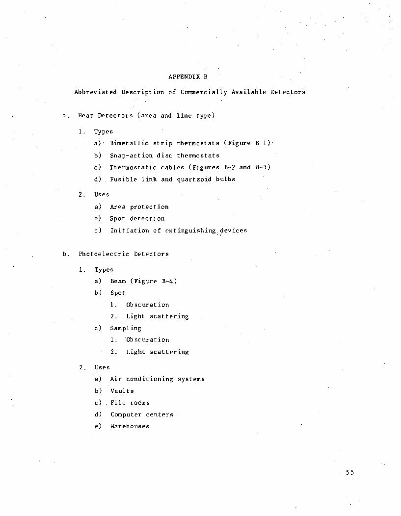
APPENDIX B
Abbreviated Description of Commercially Available Detectors
a. Heat Detectors (area and line type)
1. Types
a) Bimetallic strip thermostats (Figure B-i)
b) Snap-action disc thermostats
c) Thermostatic cables (Figures B-2 and B-3)
d) Fusible link and quartzoid bulbs
2. Uses
a) Area protection
b) Spot detection
c) Initiation of extinguishing devices
b. Photoelectric Detectors
1. Types
a) Beam (Figure B-4)
b) Spot
1. Obscuration
2. Light scattering
c) Sampling
1. Obscuration
2. Light scattering
2. Uses
a) Air conditioning
b) Vaults
c) File rooms
d) Computer centers
e) Warehouses
systems
55

c. Ionization Detectors
I. Types
a) Ionization (Figures B-5 and B-6)
b) Resistanance grid
c) Combination ionization/resistance grid
2. Uses-similar to photoelectric detectors
d. Flame Detectors (Figure B-7)
1. Types
a) Ultraviolet
b) Infrared
2. Uses
a) Any industrial or warehousing operations
b) Spot protection
c) Control of fixed extinguishing systems
d) Explosion suppression
THERVIOSTAT - FIXED TEMPERATUREBIM'IETALLIC TYPE
Figure B-i
56
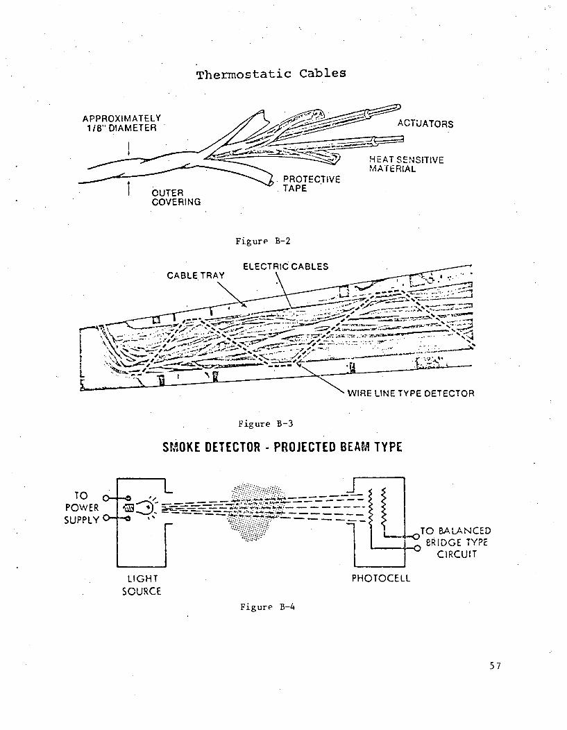
Thermostatic Cables
APPROXIMATELY1 18' DIAMETER
HEAT SENSITIVEMATERIAL
I OUTERCOVERING
PROTECTIVETAPE
Figure B-2
- -. ~ _ __ zZ~~J- ~/r~- -~
* r ~. ________-
% - 4.--
- - - *YA
WIRE LINE TYPE DETECTOR
Figure B-3
SMOKE DETECTOR - PROJECTED BEAM TYPE
TOPOWER
SUPPLY LL-0 TO BALANCED-0 BRIDGE TYPE
CIRCUIT
LIGHTSOURCE
PHOTOCELL
Figure B-4
57
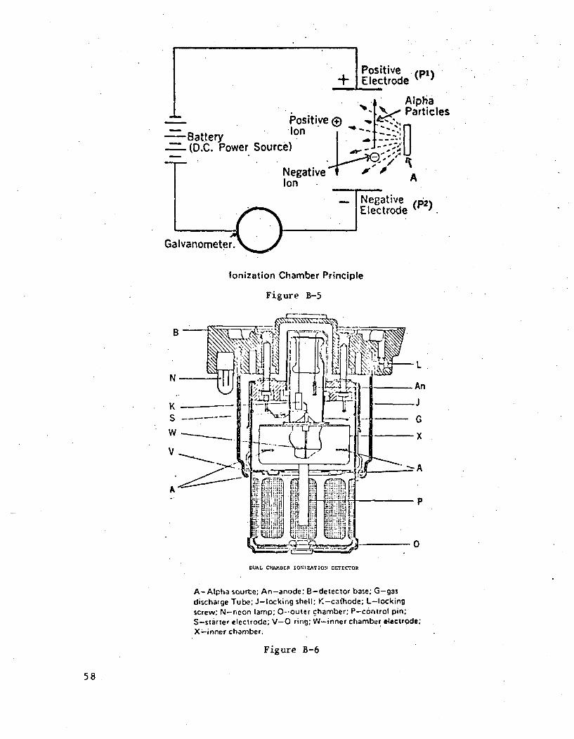
Ii-Battery- (D.C. Power Sourc
Positive+ Electrode (p1)
Alpha'• .iti e -, ~ ParticlesPositive + ,-.'',,~= d--.-.n
Negative " AIon
)NegativeT..,mt-trnr.. (P2)
Galvanometer.
Ionization Chamber Principle
Figure B-5
L
DUAL CHAMBER IONIZATION DETECT.OR
A-Alpha sourte; An-anode; B-detector base; G-gasdischarge Tube; J-locking shell; K-cathode; L-lockingscrew; N-neon lamp; 0--outer chamber; P-control pin;S-starter electrode; V-0 ring; W-inner chamber electrode;X-inner chamber.
Figure B-6
58
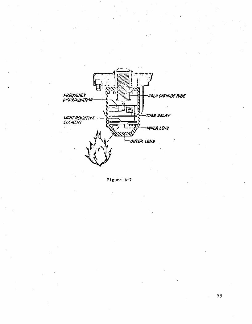
FR!4VEWCYD/sc//4/IAMT/oN-
UG/ITYUS~srlvsEC: esWr
-C0L0 CAh7X7Z4X
Figure B-7
59
DISTRIBUTION:
US Nuclear Regulatory Commission(118 copies for RP)Div. of Document ControlDistribution Services Branch
7920 Norfolk AvenueBethesda, MD 20014
US Nuclear Regulatory Commission (50)Office of Standards Div.
MS-354NLWashington, DC 20555Attn: D. P. Notley
4000 A. Narath4410 D. J. McCloskey
4414 D. L. Berry (30)4414 C. B. Varnado4442 L. J. Klamerus4541 J. A. Milloy4550 R. M. Jefferson4551 R. E. Luna4551 E. E. Minor8266 E. A. Aas3141 T. L. Werner (5)3151 W. L. Garner (3)
For DOE/TIC (Unlimited Release)
3172-3 R. P. Campbell (25)For NRC Distribution to NTIS
60