o — , o o 's-iii · • rain gear • work gloves with ... prior to initial site entry of...
TRANSCRIPT

§ sI*OC uJ
|O
_ — , _ O Oo
!SUJ V)•3•0 fc n ° S o e« P-«±J_?? .-esc-r &if£«tt-s
Ill-si!-3en E • o .5 5 (=Po
(O
u
wJl<A
?f
o
n n
e o10 10 E6 d 10I I
d
o53
O
J -fi» S^ IS"? 'C
•g ~E i* a >« oi-
d's-iiii -^ --s 9 i 8 -1dsbuild
tow
al sto
rd, e
arb
poe ica ar ca
n n w
00*•• «*•- 6I9" 8v> O 10
1 1 •
"Sa
0B
* 5^ -5
! 10 iC
•
52 uS
U(D
u•g
O O f*
I I I
8R30I689

oaCOU
€0
6(OU
ozcooUJccUJ
ouzUJ<0occ
3oc
••
o. 3 ?S e 5.S !£.!€ !.[
ber
tou•o
uo
1
- «- n
5
Uo
>
uo
oz
in
£ oa oCO O
I
flR30!690

TABLE 1-2
POTENTIAL PHYSICAL HAZARDS ENCOUNTERED DURING ONSITE SOILS INVESTIGATION
AVTEX FIBERS SITE
Potential PhysicalHazard
Electrocution,explosion
Felting objects,flying objects
Manual lifting
Engulfment
Eye, skin irritation
Heet stress, heatstroke
Hazard Source/Location
Drill rig in contact withoverhead/underground power lines,utilities.
Mechanical failure of drill rig equipment,stress feilurs of boring augers, carelessdrilling practices.
Loading, unloading and set up of drillingequipment.
Open impoundments, spray ponds,ditches.
Eye, skin contact with contaminatedsoils, hands. Use of solvent todecontaminate sampling equipment anddrilling.
High summer temperatures combinedwith physical exertion and wearing ofPPE.
Hazard Control
Keep 20 feet from power lines. Contact utilities toidentify underground utilities. Review StandardOperating Procedures (SOPs) for drilling operations,tower derrick before moving rig.
Safety inspection of rig prior to start of work (andeach day). Follow SOPe for drilling operations,personal protective equipment (PPE), deity safetybriefings.
Use proper lifting techniques. Get help when load istoo heavy.
Identify hazardous areas prior to rig set up. Usecaution, safety ropes and harnesses.
PPE, use caution, avoid hand-to-facs contact.
FTSH leader to monitor personnel for symptoms,provide adequate work-rest regime with plenty offluids.
f C;U7387\HASP\TBU-2.HM S/8/S3 8:M 1 j_g fl R 3 0 I 6 Q

Ungraded Protection Level. Level C
• Requirements of Modified Level D• Air-purifying respirators (APRs) equipped with organic vapor/dust, mist cartridge
The SSHS will determine if upgrade or downgrade of protection levels is warranted.
4.0 AIR MONITORING REQUIREMENTS
The air monitoring requirements established In Table 1-3 shall be used during the onsite soilsinvestigation activities. Action levels established in Chapter 9.0 of the HASP shall be used.
5.0 ENGINEERING CONTROLS, SAFETY EQUIPMENT AND INSPECTIONREQUIREMENTS
5.1 Engineering Controls
—^ The engineering controls to be used will consist of the machine guarding devices on the drillrig to guard against moving parts such as gears, ropes, chains, chain sprockets, etc., asspecified in the Drilling Safety Guide, 1991 Edition, International Drilling Federation.
5.2 Safety Equipment
In addition to the PPE requirements, the following safety equipment will be required:
• First-aid kit (drill rig and support vehicle)• Fire extinguisher (drill rig and support vehicle)• Eyewash fountain located In support zone• Two-way radio communication with security guard and Site Manager• Rain gear• Work gloves with leather palm or equivalent
• C:\27307\HA8P\APPB40IJt4S S/6/93 11:11 • 1-9 fl R 3 Q 1 6 9 2

TABLE 1-3
AIR MONITORING REQUIREMENTS FOR ONSITE SOILS INVESTIGATION
AVTEX FIBERS SITE
Instrument
Organic Vapor Analyzer(OVA) or PhotoionizationDetector (PID)
Exptosimeter
Colorimetric carbondisutftde and hydrogensulfide detector tubes
MonitoringFrequency
Establish background
Periodic
Periodic
Periodic (if VOCreading is ebove4ppm)
Location
General area
Headapace of borehole andsample, breathing zone
Heedepace of borehole,general area
Headspece of borehole andsample, breathing zone
Comments
Not required for surfacesampling
Not required for surfacesempling
F &V27M7\HASPVTBU.3>lfta 5/8/939:01 1 '"10 A P *3 fl I £ Q

5.3 Inspection Requirements
Prior to initial site entry of the drill rig, the Site Safety and Health Supervisor (SSHS) shallconduct a safety inspection of the rig to ensure that all safeguards are in place and securelyfastened, the brakes work, and that there are no loose bolts on parts. Prior to each day'swork, the senior drill rig operator is responsible for conducting a maintenance and safetyinspection of the drill rig.
. i"
6.0 DECONTAMINATION
Decontamination setups and procedures shall be in accordance with Chapter 8.0 of the HASP.Prior to initiation of activities at each borehole, the support zone, contamination reductionzone (CRZ) and exclusion zone will be identified by the FTSH leader. A decontamination areawilt be set up in the CRZ equipped to provide personnel decontamination at Level C protection.
All drilling equipment, including the drill rig and its transportation system, shall bedecontaminated at the vehicle decontamination pad located at the waste water treatment plant(WWTP). Decontamination of this equipment shall be conducted prior to entering theexclusion zone, after each boring, and before exiting the site. The drill rigs and associatedequipment shall be decontaminated by using high-pressure steam and a water rinse.
Personnel decontamination and decontamination of air monitoring equipment and samplingequipment shall take place in the CRZ for that particular borehole. Air monitoring equipmentshould be bagged or wrapped in plastic to avoid contamination, if not they shall be wiped offwith a damp cloth before entering the support zone. Personnel shall decontaminate inaccordance with the decontamination procedure established in the HASP.
7.0 EMERGENCY RESPONSE ACTIONS
Emergency response actions shall follow the procedures established in the Emergency*
Response Plan (ERP) (Chapter 14.0 of the HASP).
• O\27i«7\HA3TWPENO(.HAS 6/4/9311:11 11 M 1 fl R 1 0 I 6 Q ll

7.1 Emergency Evacuation Routes
The FTSH leader shall establish two emergency evacuation routes upon completion ofestablishing the work zones. These evacuation routes should take Into consideration the winddirection and the proximity of any additional hazards (I.e., lagoons', spray ponds, ditches, etc.).This shall be done for each borehole.
7.2 Assembly Point
In the event of eny emergency evacuation, personnel shall report immediately to the Avtexadministration office.
B GA273S7\HASnAPPEM]LH&S 878/9111:1* 12 1-12 A R T 0 I fi Q S

APPENDIX J
OFFSITE SOILS INVESTIGATION
AVTEX FIBERS SITE
AR30I696

TABLE OF CONTENTS
Section Page
1.0 DESCRIPTION OFTASKS ..................................... J-1
1.1 Personnel ...................................... J-11.2 Tasks to be Performed ............................. J-11.3 Unique Problems ................................. J-2
2.0 HAZARD IDENTIFICATION AND ANALYSIS ........................ J-2
2.1 Chemical Hazard Analysis ........................... J-22.2 Physical Hazard Assessment ......................... J-22.3 Biological Hazards ................................ J-22.4 Fire and Explosion Hazard Risk ........................ J-2
3.0 PERSONAL PROTECTIVE EQUIPMENT REQUIREMENTS ................ J-6
4.0 AIR MONITORING REQUIREMENTS .............................. J-6
5.0 ENGINEERING CONTROLS, SAFETY EQUIPMENT AND INSPECTIONREQUIREMENTS ........................................... J-6
i J 6.0 DECONTAMINATION ........................................ J-7
7.0 EMERGENCY RESPONSE ACTIONS .............................. J-7
7.1 Emergency Evacuation Routes ........................ J-77.2 Assembly Point .....'............................. J-7
LIST OF TABLES
Table
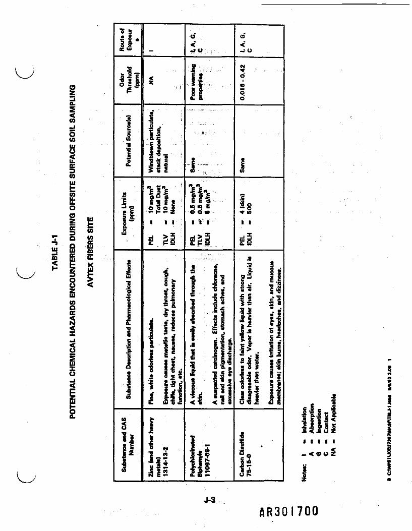
J-1 Potential Chemical Hazards Encountered During the Offsite Soils Investigation J-3
J-2 Analysis of Physical Hazards with the Offsite Soils Investigation .......... J-4
J-3 Biological Hazards with the Offsite Soils Investigation ................. J-5
B C\37387\HA*FWPENOJ.HA3 S/B/93 2:81 I A P 1 fl I fi Q 7

NOTE:
The health and safety hazard analysis for the individual tasks to be performed within thismanagement unit were prepared from project planning documents and existing siteinformation. The hazard analysis will need to be evaluated and updated based uponactual procedures and equipment to be utilized prior to the initiation of management unitsite activities. 7- , •- .
1.0 DESCRIPTION OF TASKS
1.1 Personnel , ,
The offsite soils investigetion will be conducted under the direction of the Field OperationsLeader (FOL) with assistance from the Site Safety and Health Supervisor (SSHS) by thefollowing personnel:
• Field Team Leader (FTL)• Sampling paperwork person
1.2 Tasks to be Performed
Windblown Paniculate—Air samples will be collected at three locations using high-volumesamplers and polyurethane foam samplers. These samples will be collected over a 24-hourperiod, once a week for six weeks.
Stack Deposition—After determining the most probable area of offsite stack deposition via airdispersion modeling, samples wilt tie collected from soils that have not been disturbed (e.g.,national forest). These samples will be collected in six locations at a depth no greater thanthree inches.
• C\27387\HASfWPENOJ.H*3 8/6/U £91 1 J-1.
BR3QI698

1.3 Unique Problems
The problem of biological hazards poses a unique problem for the field investigation team.Collecting samples in wooded areas exposes personnel to a variety of insects, snakes, andpoisonous plants.
2.0 HAZARD IDENTIFICATION AND ANALYSIS
2.1 Chemical Hazard Analysis
Table J-1 provides a chemical hazard analysis for personnel engaged in the offsita surface soilsampling. Personnel conducting ambient air sampling using the high-volume samplers are notexpected to be exposed to chemical hazards of any appreciable risk.
2.2 Physical Hazard Assessment
Table J-2 provides an assessment of the physical hazards associated with the offsite soilsinvestigation.
2.3 Biological Hazards
Table J-3 summarizes the potential biological hazards associated with sampling in a woodedarea.
2.4 Fire and Explosion Hazard Risk
The potential for fire and explosion hazards during this investigation is minimal. The greatestconcern for a fire hazard is forest fires. No smoking will be permitted in wooded areas.
• CAJ73S7WAS*AP«NOJ.H4* BO/M 2:81 2 J-2 f
oz£ll
I1
sll5 a. Io o oI I I
i 34i3
u
0.
ic 10 bO O 10
I i i
(9*
-TO
oo*
I i
a
J-3SR30I700

TABLE J-2
ANALYSIS OF PHYSICAL HAZARDS WITH OFFSITE SOILS INVESTIGATION
AVTEX FIBERS SITE
Physical Hazard
Slipa, trips, falls
Pinch points
Eya, akin irritation
Manual lifting
Haat strass
Vehicular traffic
Hazard Sourca/Location
Unstabla terrain, wet terrain, open gullies orsmall cliffs
Sat up and breakdown of high-volumesamplers
Contaminated dust, dirt during sampling;•olvanta used in decontaminating samplingdevices
Set up and breakdown of high-volumesamplers
High summer temperatures in coordinationwith work activities and PPE
Work alongaida roadways, crossing roads
Hazard Control
Safsty rope. Use extreme caution innegotiating wooded areas.
Use caution
Paraonal protective equipment (PPE), dilution ofsolvents, caution in use of solvente endsampling procedures
Use a partner to help perform lift. Use properlifting techniques.
Field Team Safety and Health (FTSH) leadermonitor personnel for symptoms of heat stressand administer first aid. Work-reel regime Inaccordance with ACGIH, WBQT index.
Use caution, avoid work alongsids roadwaya
• C:\WW1 UOW73S7VUWT8U-2.H** B/B/U3:OS 1 •"
flR30!70l

TABLE j-3BIOLOGICAL HAZARDS WITH THE OFFSITE SOILS INVESTIGATION
AVlTEX FIBERS SITE
PotentialBiological Hazard
Insect bites
Lyme Diaaaaa
Snake bites
Poisonous plant*
Hazard Source
Various Insects, bees, chiggers, .mosquitos, etc.
Ticks ,;;;,:•!,•.' "
Eastsm Rattlesnake, Copperhead
Poieon Ivy. Poiaon Sumac. Poison Oak
Hazard Control
Wear long pants. Insect/tick repellant, monitor forallergic reaction after bite
Wear long pants, Insect/tick repellant, wear a cap,check body for ticks
Wear leather boots, long pants, inspect areae carefully
Wear long pants, wash affected area immediately withsoep and water, monitor for allergic reaction
I CA27387\HAtP\TBU-J.HAS 8/5/93 3:M 1 J-g
RR30I702

3.0 PERSONAL PROTECTIVE EQUIPMENT REQUIREMENTS
>Minimum Protection Requirements. Level D Protection
• Hard hat• Work clothes• Safety boots with steel toe• Safety glasses• Leather palm work gloves or equivalent• Neoprene outer gloves (to be worn during soil sampling and equipment
decontamination)
Upgraded Protection Requirements. Modified Level D Protection—Not applicable
4.0 AIR MONITORING REQUIREMENTS
No air monitoring is anticipated during these surface sampling operations.>
5.0 ENGINEERING CONTROLS, SAFETY EQUIPMENT AND INSPECTIONREQUIREMENTS
There are no specific engineering controls required for this management unit. A generalinspection of all sampling locations should be conducted to identify the presence of snakes,poisonous plants, sinkholes, gullies or pits, or any other potentially hazardous condition.
The following safety equipment will be required in addition to the PPE mentioned above:
• Plastic sheet for ground cover• Rain gear• Safety rope• Two-way radio communication with security guard and Site Manager• First-aid kit (in support vehicle)• Fire extinguisher (in support vehicle)
• CAttM7\HASP\APP£NOXH*» S/9/93 2.-81 • J-6 HR3GI703

Eyewash fountain (in support vehicle)Hand pump water spray bottle (in support vehicle)
6.0 DECONTAMINATION
Gross contamination is not anticipated during the management unit activities. Personnel wiltbe required to decontaminate gloves and sampling equipment using a detergent wash andpotable water rinse. Personnel should wash all exposed skin before lunch and at theconclusion of the day's activities.
7.0 EMERGENCY RESPONSE ACTIONS
Emergency response actions will be conducted in accordance with the Emergency ResponsePlan (ERP) provided in the Health and Safety Plan (HASP).
7.1 Emergency Evacuation Routes
During the safety inspection of each sampling location, the FTSH leader will identify twoevacuation routes and communicate that information to the FTL.
7.2 Assembly Point "
In the event of an emergency evacuation, the team members shall assemble at the supportvehicle unless the vehicle is located in close proximity to the emergency situation.
B &U7M7\KASP*PPENQJ.H*S 6/8/93 Ml 7 J-7
flR30l70l*

APPENDIX K
ECOLOGICAL ASSESSMENT
AVTEX FIBERS SITE
flR30i705

TABLE OF CONTENTS
Section Paoe
1.0 DESCRIPTION OF TASKS ...................................... K-1
1.1 Personnel ...................................... K-11.2 Tasks to be Performed ............................. K-21.3 Unique Problems ................................. K-2
2.0 HAZARD IDENTIFICATION AND ANALYSIS ........................ K-2
2.1 Chemical Hazard Analysis ........................... K-22.2 Physical Hazard Assessment ......................... K-22.3 Biological Hazards ................................ K-62.4 Fire and Explosion Hazard Assessment .................. K-6
3.0 PERSONAL PROTECTIVE EQUIPMENT REQUIREMENTS ................ K-6
4.0 ENGINEERING CONTROLS, SAFETY EQUIPMENT AND INSPECTIONREQUIREMENTS ........................................... K-6
5.0 DECONTAMINATION ........................................ K-8
6.0 EMERGENCY RESPONSE ACTIONS .............................. K-8
6.1 Emergency Evacuation Routes ........................ K-86.2 Assembly Point .................................. K-8
LIST OF TABLES
Table
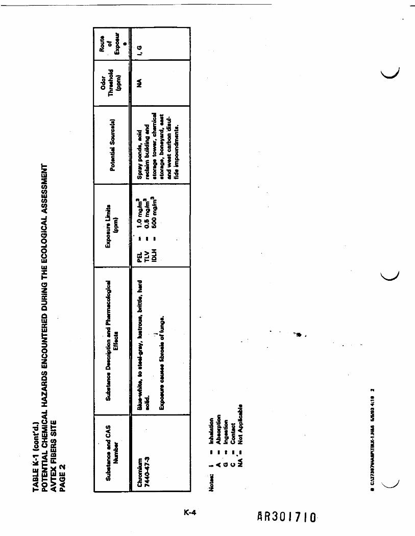
K-1 Potential Chemical Hazards Encountered During the Ecological Assessment .. K-3
K-2 Analysis of Physical Hazards with the Ecological Assessment ............ K-5
K-3 Biological Hazards with the Ecological Assessment ................... K-7
B C:\27387\HASP\APPENOItHtS 6/8*3 4:08 I flR30!706

NOTE:
The health and safety hazard analysis for the individual tasks to be performed within thismanagement unit were prepared from project planning documents and existing siteinformation. The hazard analysis will need to be evaluated and updated based uponactual procedures and equipment to be .utilized prior to the initiation of management unitsite activities.
1.0 DESCRIPTION OF TASKS
1.1 Personnel j ,, .
The Ecological Assessment (EA) general field operations will be conducted under the directionof the Field Operations Leader (FOL). The following personnel shall be used for each subtaskof the EA:
Terrestrial Vegetation and Resident Wildlife Survey
• .- i. • •. -.,'•>!": J .• '• Field Team Leader {FTD/ecology trained• One biologist technician
Floodplafn Determination - - - : .
• FTL/surveyor• One surveyor technician
Wetland Determination f . ; ,. „ t- ;*•.'-
• FTUwetiands biologist• One biologist technician
B C:\373a7VUSPMPPEMOK.HU 9/5/934:08 1 K-1 BR3Q I 707

1.2 Tasks to be Performed
Terrestrial Vegetation and Resident Wildlife Survey—A field survey will be conducted of theonsite flora and fauna, and the presence of any threatened or endangered or rare species willbe identified. A field survey will be conducted to observe wildlife and resident migratory birdsfor abnormal behavior or physical harm. Items such as leaves, branches, animal remains ordroppings may be collected during these field surveys.
Floodplaln Determination—Elevations along the South Fork will be surveyed onsite and 100-and 500-year floodplain contours will be flagged.
Wetland Determination—Wetland identification, delineation, and classification will beconducted on or adjacent to the Avtex Fibers Site. This procedure will include a determinationof the dominant plant species, an evaluation of soil along the wetland boundary, and anevaluation of surface water hydrology in the wetland areas.
1.3 Unique Problems
The problem of biological hazards poses a unique problem for the field investigation team.Conducting investigations may expose personnel to a variety of insects, snakes, andpoisonous plants.
2.0 HAZARD IDENTIFICATION AND ANALYSIS
2.1 Chemical Hazard Analysts
Table K-1 provides a chemical hazard analysis for personnel engaged in the EA. Personnelconducting surveys offsite are not expected to be exposed to chemical hazards of anyappreciable risk.
2.2 Physical Hazard Assessment
Table K-2 provides an assessment of the physical hazards anticipated for the EA.
8 C:\27387\HASnAPPOOCHM 8/8/93 4:0* 2 K-2 1j R 3 fl I 7 0 fl

COCOUlCO3i5oouUJuiHOZs £i 5« w* H PCy P Ss i c
^ y *" = ^v_/ o tw S2 <
COQCC<
X
8»-« -°cc" -fO
S « • .B ,
Oo<o
1
e o e o»- K
i! 21
t
O <i 10
I I I
S
i
e
I
iiiil
&ia.
flR30!709
m22CO
CO
o53OUUlUJ
OZccooUlccUl
oosCOQ
|
j
«•» O UJ_• 3 r"V UJ CO
8o|^ rf S^ixwg H t g1- 0. < 0.
a "o 5 •
illh-
5I
1I(L
I
ll1
|.
3 ui'g|.1
i
(0
u
^13 §1 zS
o
i
|i|.II ||| 1* S £ 1 1 c>. .5 9 9 f .5S -§ k k -a •» N. • « iS
«t1HO 10 2^ o S1 1 1^ I
a! K 9
4i
I !i 1J S
• Sa 3
Is 18 S
1?liu r»
•
,
• , "» ,
||| e f& s 5
llilfJ < i O Z
i i t i i*- < 0 U S
12104 AR30I7IO

TABLE K-2 ' -^
ANALYSIS OF PHYSICAL HAZARDS WITH THE ENVIRONMENTAL ASSESSMENT
AVTEX FIBERS SITE
Potential PhysicalHazard
Slips, trip*, fall*
Eye, akin Irritation
Haat atraaa
Vahicular traffic
Engulfmant
Hazard Source/Location
Unatabla terrain, wat terrain, opan gullies oramall cliffa ' ,i -I »u.:
Contaminatad duat. dirt during sampling
High aummar tamparaturaa In coordinationwith work activities and PPE
Work alongside roadways, crossing roada
Opan impoundments, ditchea, apray ponds,baaina
Hazard Control
Safety ropa. Uaa axtrama caution Innegotiating woodad areas.
Psrsonal protective equipment (PPE)
Monitor personnel for eymptoms of haat stressand administer first aid. Work-rest regime Inaccordance with ACGIH. WBGT Index.
Uaa caution, avoid work alongside roadways
Identify hazardous araaa prior to survey, ueecaution
• C:U73B7\HMP\TBU.2.HA3 878/844:20 1 K-6 fl OOfl I T I t

2.3 Biological Hazards
Table K-3 summarizes the potential biological hazards anticipated during EA activities.
2.4 Fire and Explosion Hazard Assessment
The potential for fire and explosion hazards during the EA Is minimal. The greatest concernfor a fire hazard is an ignition of waste materials contained in the viscose, sulfate, and fly ashbasins as well as brush and wooded areas. No smoking will be permitted in these areas.
3.0 PERSONAL PROTECTIVE EQUIPMENT REQUIREMENTS
The following are the PPE requirements for the EA:
Minimum Protection Level. Modified Level D
• Hard hat• Work clothes• Safety boots with steel toe• Safety glasses• Leather palm work gloves or equivalent
Upgraded Protection Level. Level C—Not applicable
4.0 ENGINEERING CONTROLS, SAFETY EQUIPMENT AND INSPECTIONREQUIREMENTS
There are no specific engineering controls required for this management unit. A generalinspection of all survey locations should be conducted to identify the presence of snakes,poisonous plants, sinkholes, gullies or pits, or any other potentially hazardous condition.
The following safety equipment will be required in addition to the PPE mentioned above:
8 C:\27U7WASPWPPENOILMU S/B/814 C • K-6 AR30I7I2

TABLE K-3
BIOLOGICAL HAZARDS WITH THE ECOLOGICAL ASSESSMENT
AVTEX FIBERS SITE
PotentialBiological Hazard
Insect bites
Lyma Diaaaaa
Snake bites
Poisonous plants
Hazard Source \
Various insects, baas, chiggare,moaqultoe, ate.
Ticka
Eastern Rattlesnake, Copperhead
Poison Ivy, Poiaon Sumac, Poison Oak
Hazard Control
Wear long pants. Insect/tick repellant, monitor forallergic reaction after bite
Wear long pants. Insect/tick repellant, wear a cap,check body for ticks
Wear leather boots, long pants, inspect areaa carefully
Wear long pants, wash affected area immediately withaoap and water, monitor for atlargic reaction
8 C:\27387WA«PlTBUMJIa4 8VB/9J 4:28 1 K*7A D Q fl I 7 I

• Rain gear• Safety rope• Two-way radio communication with security guard and Site Manager• First-aid kit (in support vehicle)• Fire extinguisher (in support vehicle)• Eyewash fountain (in support vehicle)• Hand pump water spray bottle (in support vehicle)
5.0 DECONTAMINATION
Gross contamination is not anticipated during the management unit activities. Personnel willbe required to decontaminate gloves and any survey equipment using a detergent wash andpotable water rinse. Personnel should wash all exposed skin before lunch and at theconclusion of the day's activities.
6.0 EMERGENCY RESPONSE ACTIONS
Emergency response actions will be conducted in accordance with the Emergency ResponsePlan (ERP) provided in the Health and Safety Plan (HASP).
6.1 Emergency Evacuation Routes
During the safety inspection of each sampling location, the FTSH leader will identify twoevacuation routes and communicate that information to the FTL.
6.2 Assembly Point
In the event of an emergency evacuation, the team members shall assemble at the supportvehicle unless the vehicle is located in close proximity to the emergency situation.
8 C:\273S7\HASnAFPENDSU1tt 6WH4;Oa • K-3 AR30I7II*
APPENDIX L
RIVER INVESTIGATION
AVTEX FIBERS SITE
AR30I7I5

TABLE OF CONTENTS
Section Page
1.0 DESCRIPTION OF TASK ....................................... L-1
1.1 Personnel ....................................... L-11.2 Scope of Work .................................... L-21.3 Unique Problems .................................. L-2
2.0 HAZARD IDENTIFICATION AND ANALYSIS .......................... L-3
2.1 Chemical Hazard Analysis ............................ L-32.2 Physical Hazard Assessment .......................... L-32.3 Biological Hazards ................................. L-32.4 Fire and Explosion Hazard Risk ......................... L-3
3.0 PERSONAL PROTECTIVE EQUIPMENT REQUIREMENTS ................. L-3
4.0 AIR MONITORING REQUIREMENTS ............................... L-7
5.0 ENGINEERING CONTROLS, SAFETY EQUIPMENT AND INSPECTIONREQUIREMENTS ............................................ L-7
6.0 DECONTAMINATION ......................................... L-8
7.0 EMERGENCY RESPONSE ACTIONS ............................... L-8
7.1 Emergency Evacuation Routes ......................... L-87.2 Assembly Point . ....v............................. L-8
LIST OF TABLES
Table
L-1 Potential Chemical Hazards Encountered During the River Investigation ...... L-4
L-2 Analysts of Physical Hazards with the River Investigation ................ 1-5
L-3 Biological Hazards with the River Investigation ....................... L-6
H CiV27387\HA8P\APPEMX_Haa 8/0/838:23 1 RR30I7I6

NOTE:
The health and safety hazard analysis for the individual tasks to be performed within thismanagement unit were prepared from project planning documents and existing siteinformation. The hazard analysis will need to be evaluated and updated based uponactual procedures and equipment to be utilized prior to the initiation of management unitsite activities.
1.0 DESCRIPTION OF TASKS ^
1.1 Personnel :t- ;;
The river investigation will be conducted under the direction of the Field Operations Leader(FOL). Personnel assigned to the field activities for this investigation shall be organized asfollows:
Water and Sediment Investigation
• Field Team Leader (FTL)/samp!er• Sampling paperwork person
Bioassessment Investigation
• FTL/aquatic biologist• One biologist technician
' * ",fii f '' ' -' ( i . f f i' IT H
Macroinvertebrate Survey .......; \ •• , •
• FTL/macroinvertebrate biologist• One Aquatic biologist
* *
• One or two biologist technicians
H C:\27387\HA3IWPENOLH4S 0/8/838:23 1 L'1
AR30I7I7

Fish Survey
• FTUflshery biologist• One aquatic biologist• Two biologist technicians
1.2 Scope of Work
The scope of field activities for this management unit shall consist of an assessment of waterand sediment quality in the South Fork, North Fork, Cabin Run, Punches Run, Happy Creek,and the Shenandoah River. Additionally, a bioassessment of the South Fork and ShenandoahRiver will be conducted which will include the following:
• Habitat assessment• Macroinvertebrate survey •• Fish survey
1.3 Unique Problems ^
The following are unique problems associated with the river investigation:
• Deep water and/or swift current• Boat traffic, boating safety• Biological hazards* Holes in river bottom
Alt personnel assigned to field activities associated with the river investigation shall reviewthe Gannett Fleming Field Safety Manual Section II D regarding boating safety.
H C:\273S7\HA8PWPeNOlH4S 9/0/83 8:23 2 L-2 • P» O n I "f I ft

2.0 HAZARD IDENTIFICATION AND ANALYSIS
2.1 Chemical Hazard Analysis |f i
Table L-1 provides a chemical hazard analysis for personnel engaged in the river investigation.
2.2 Physical Hazard Assessment
Table L-2 provides an assessment of the physical hazards associated with the riverinvestigation. t - " ; - ,
2.3 Biological Hazards ^ 1
Table L-3 summarizes the potential biological hazards associated with the river investigation.i "; 1J i. ,
2.4 Fire and Explosion Hazard Risk
! • ; • * - . 'The potential for fire and explosion hazards during this investigation is minimal. The greatestconcern for a fire hazard is forest fires. No smoking will be permitted in wooded areas. The
ij • :refueling of motor boats also presents a fire and explosion hazard. This activity shall beconducted with the engine off, using approved 129 CFR 1910.155 (c)(3)J containers equippedwith automatic closing cap and flame arrester.
I •'• T ';. ':3.0 PERSONAL PROTECTIVE EQUIPMENT REQUIREMENTS
- - £• v : ;
Minimum Protection Requirements. Level D Protection
• Work clothes• Safety boots with steel toe '• Safety glasses ' .\• Leather palm work gloves or equivalent
H C:\27387\HA8P\APPCNOLHA8 8/8438:23 3 L-3 flR30l7!9

o52COUJ
zccUl
5:UJX
O uiQ tUJ CO
I g g3 § 2S o "•H § gs s?
Ulu
i I I 111 slli 2» il n 11 ;< i . *i i ai3CO . . . _ -...*,. . ! . „ . . * _ . .
< i o n > a . .a--i" " • i * ? • i . .33 is a i i o zoUJ
u
UJ
2 I——1———I———I———TTTT—I———I ji,• W m•3 S 8S3!i i i_ < o
8
L-4 AR30I720

TABLE L-2 &,. r• ' .,',= ,.' V *'
POTENTIAL PHYSICAL HAZARDS ENCOUNTERED DURING RIVER INVESTIGATIONS
: AVTEX FIBERS SITE
Potential PhysicalHazard
Slips, trips, falls
Pinoh points
Eye, skin Irritation
Manual lifting
Heat stress
Boat accident
Cold stress
Drowning
Cuts, ecrapes,punctures
Electrocution
Hazard Source/Location
Unstable terrain, wet terrain,opan gullies or small ctiffa, junstable river bottom. M- *" -|
Set up, breakdown and uaa of jaamplera and boat. :- ;
Contaminated water, sediment """]during sampling; aotvanta used litdecontamination of sampling , r jdevices. I
Set up, breakdown and uaa ofsamplers, docking and launchingboat.
High summer temperatures incoordination with work activitieeand PPE.
Other boat traffic on river, otherobjects (trses, rocks, etc).
Falling into water, drenchingclothes during spring months.
Fall out of boat, alip or tip intoriver, step into deep river bottomhole, swift current.
Jagged rocks, underwater trash,debris, limbs, etc.
Dee of energized equipment.electrical storm.
Hazard Control
Safety rope. Approved flotation device. Use extremecaution in negotiating wooded areas and river banks andbottom.
Use caution.
Personal protective equipment (PPE), dilution of solvents,caution In use of solvents and sampling procedures.
Use a partner to help perform lift. Uae proper liftingtechniques.
Monitor personnel for symptoms of heat etress andadminister first eid. Work-rest regime In eccordance withACGIH. WBGT index.
Use caution, avoid high boat traffic areas and be alert forunderwater limbs, rocks and trees. Approved flotationdevice.
Monitor for cold stress symptoms, remove wet clothing, puton dry clothing.
Uae extreme caution at all times. Identify hazardous areasprior to start of activities. Coast Guard approved personalflotation devices.
Leather boots with hip waders, use extreme caution.
Use clear signal to clear all personnel prior to electro-shocking operatione. Do not uee other energized equipment.Do not work during electrical thunder storms.
F C:U7387\HASP\TBU--2.H*S B/6/» 12:06 1 L"5 Y • n O D 1 *7 O I

TABLE L-3
BIOLOGICAL HAZARDS WITH THE RIVER INVESTIGATION
AVTEX FIBERS SITE
PotentialBiological Hazard
Insect bites
Lyme Disease
Snake bitee
Poisonous plants
Hazard Source
Varioua insects, beaa, chiggera,mosquitos, etc.
Ticks
Eaatem Rattlesnake, Copperhead
Poison Ivy, Poison Sumac, Poison Oak
Hazard Control
Wear long panta, inaect/tick rapeltant, monitor forallergic reaction after bite
Wear long panta, inaect/tick repellant, wear a cap,check body for ticke
Wear leather boots, long panta, inspect areaa carefully
Wear long pants, wash affected area immediately withsoap and water, monitor for allergic reaction
H C:\273S7WASP\TBll-3.HM 8/0/83 9:40 1
AR30I722

4.0 AIR MONITORING REQUIREMENTS
No air monitoring is required for this management unit unless the Site Safety and HealthSupervisor (SSHS) determines that air monitoring is necessary upon evaluation of onsitecircumstances.
5.0 ENGINEERING CONTROLS, SAFETY EQUIPMENT AND INSPECTIONREQUIREMENTS _.
There are no specific engineering controls required for this management unit. A generalinspection of all sampling locations should be conducted to identify the presence of snakes,poisonous plants, sinkholes, gullies or pits, or any other potentially hazardous condition.
The following safety equipment will be required in addition to the PPE mentioned above:
• . Plastic sheet for ground cover •
• Rain gear
• One-hundred foot safety rope with throw buoy aboard each boat." - i i.' - * , n. . "' " .
• Two-way radio communication with security guard and Site Manager
• First-aid kit (in support vehicle)
• Fire extinguisher (in support vehicle)
; • U'.. Yih'J • '• 'L ••
• Eyewash fountain (in support vehicle)
• Hand pump water spray bottle (in support vehicle)
H C:\273S7\HASP\APPEMX-H4S 8/8/93 »: 23 7 L-7
flR30!723

• One U.S. Coast Guard approved flotation device for each person aboard eachboat . j
• Rubber hip waders
6.0 DECONTAMINATION
Gross contamination is not anticipated during the management unit activities. Personnel willbe required to decontaminate gloves, rubber hip waders, and sampling equipment using adetergent wash and potable water rinse. Sample containers should be wiped off with a dampcloth. Personnel should wash all exposed skin before lunch and at the conclusion of the day'sactivities.
7.0 EMERGENCY RESPONSE ACTIONS
Emergency response actions will be conducted in accordance with the Emergency ResponsePlan (ERP) provided in the Health and Safety Plan (HASP).
7.1 Emergency Evacuation Routes
During the safety inspection of each sampling location, the FTL will identify two evacuationroutes and communicate that information to the rest of the field investigation team.
7.2 Assembly Point
In the event of an emergency evacuation, the team members shall assemble at tha supportvehicle unless the vehicle is located in close proximity to the emergency situation.
H C:\273a7WASPNAPPO«l_HM 5/8/83 »:3J t L-3 • O O H I "I O I

APPENDIX M
VISCOSE BASINS INVESTIGATION
AVTEX FIBERS SITE
flR30!725

TABLE OF CONTENTS
Section Paoe
1.0 DESCRIPTION OF TASKS ..................................... M-1
1.1 Personnel ...................................... M-11.2 Scope of Work ................................... M-11.3 Unique Problems ................................. M-2
2.0 HAZARD IDENTIFICATION AND ANALYSIS ........................ M-2
2.1 Chemical Hazard Analysis ............................ M-32.2 Physical Hazard Assessment ......................... M-32.3 Biological Hazards ................................ M-32.4 Fire and Explosion Hazard ........................... M-3
3.0 PERSONAL PROTECTIVE EQUIPMENT REQUIREMENTS ................ M-8
4.0 AIR MONITORING REQUIREMENTS .............................. M-8
5.0 ENGINEERING CONTROLS, SAFETY EQUIPMENT AND INSPECTIONREQUIREMENTS .......................................... M-10
5.1 Engineering Controls .............................. M-105.2 Safety Equipment ................................ M-105.3 Inspection Requirements ........................... M-10
6.0 DECONTAMINATION ....................................... M-11
7.0 EMERGENCY RESPONSE ACTIONS ............................. M-11
7.1 Emergency Evacuation Routes ....................... M-117.2 Assembly Point ................................. M-12
LIST OF TABLES
Table
M-1 Potential Chemical Hazards Encountered During Viscose Basins Investigation . M-4
M-2 Potential Physical Hazards Encountered During viscose Basins Investigation .. M-6
M-3 Biological Hazards with the Viscose Basins Investigation ............... M-7
M-4 Air Monitoring Requirements for the Viscose Basins Investigation ......... M-9
• O\273a7\HASfWKNOM.H*S B/fl/93 S:33 I HR30I726

NOTE:
The health and safety hazard analysis for the Individual tasks to be performed within thismanagement unit were prepared from project planning documents and existing siteinformation. The hazard analysis will need to be evaluated and updated based uponactual procedures and equipment to be utilized prior to the initiation of management unitsite activities. ,::«.- f•.:..•
1.0 DESCRIPTION OF TASKS ; i - -
1.1 Personnel
The viscose basins investigation shall be conducted under the direction of the Field OperationsLeader (FOL). Personnel assigned to this Investigation shall be organized as follows:
Surface Soil Sampling -
, • * • • • • • . . .• Field Team Leader (FTU/geoIogist• Field Team Safety and Health (FTSH) leader/sampler• One sampling paperwork person
Borehole Drilling and Subsurface Soil Sampling', : ' . . . r-< J'iv.- - • .'• FTL/geologist „ >• FTSH leader -s. leu• Sampler , . "^ -..;•• Sampling paperwork person ;; •• Drilling crew
1.2 Scooe of Work
The scope of work for this management unit shall consist of surface soil sampling andstandard and innovative drilling procedures to conduct subsurface soil sampling.
• C:\27M7WASP\APPENOM.H&S 8/8/93 »:33 1 M-1 _ . _ __HR30I727

Surface Son Sampling— Four surface solid samples will be collected from each of the 11viscose basins and one surface soil sample will be collected from each berm adjoining the ,basins.
Subsurface Soil Borings— Four subsurface soil borings will be constructed in each basin and«
one boring at the berm adjacent to each basin up to a depth of 30 feet. In the event that thewaste contents of the viscose basins cannot support a drill rig, an innovative drilling methodwill be used. Drilling in these basins may be accomplished using a platform-mounted skid rig.A crane may be used to lower the rig and associated equipment and materials onto eachbasin. A plywood walkway may be constructed from the berm to the drilling rig for access.
1.3 Unique Problems
The following are unique problems involved with drilling operations:
• Contact with overhead power lines• Contact with underground power/utility lines• Physical hazards associated with the use of mechanical equipment ^_x• The waste contents of the viscose basins may not support a drill rig
*
All drilling operations shall be in accordance with safety procedures contained in the DrillingSafety Guide, 1991 Edition, International Drilling Federation.
In the event that viscose basin waste contents will not support the weight of the drill rig, aplatform-mounted skid rig may be used. A crane may lower the rig and all associatedequipment, not personnel, onto each basin. A plywood access walkway may be constructedfrom the berm to the drilling rig. The crane bperator will remain onsite with the crane at alltimes during the drilling and sampling activities in order to remove personnel or equipment inthe event of an emergency.
2.0 HAZARD IDENTIFICATION AND ANALYSIS•
Prior to any drilling operation, the drilling safety supervisor shall conduct a "tool box9 safety .meeting with the drill team to discuss hazards associated with the operation.
B CU73a7\KASP\APPQ(OM-HM SWM •:» 3 M-2
AR30I728

2.1 Chemical Hazard Analysis ~ =
The anticipated chemical hazards associated with this management unit are provided inTable M-1. . \
' '. ' '
2.2 physical Hazard Assessment
Table M-2 provides an analysis of the physical hazards associated with the viscose basinsinvestigation. : ;f ~' i. '
2.3 Bfofoolcal Hazards
Table M-3 provides an analysis of the bioloj ical hazards associated with the viscose basinsinvestigation.
2.4 Fire and Explosion Hazard ?
The following fire and explosion hazards exist:
• Rupture of underground gas fines/utilities• Presence of carbon disulfide i •• Presence of hydrogen sulfide . j• Presence of volatile organic vapors• Fuel spills ', '; :! j-f /• Refueling of drill rigs i
, j -K ••' "
Air monitoring requirements shall be followed to ensure that the lower explosive limit (LEDremains below 10 percent. Prior to commencement of any drilling operations, the local utility
.- .' :- \ := i'companies shall be notified in order to identify underground utility lines. Refueling of drill rigs
i swith portable containers shall be done with engine off, using approved [29 CFR1910.155(c)(3)] containers equipped with automatic closing cap and flame arrester.
• CU7387V1A8PSAPFENOM.HU 0/0/83 S:33 3 M-3 HR30I729

zoaCOUJ
zCO
1mui(AOU(A
ui
co
C Q U J5 I1Ul(Oocc
U
uiO
Ioa.
"3 21§I ioc i2
«" "2 •?•S *s io S &.c *-
Ise *** 3O OQ. (5
5ii*ui
w
Substance Deacription and Pharmacological
Effec
tooli5 J5 Z*3<fi
Uo.^-J
toO6
•5£
1-•3 w• Oe oo ,20 >
*c "c
llg\O ID r-1 1 1
ft! H S
c
Colorless white crystals or haavy
liquid. Sweet,
acri
odor.
When
inhaled, irr
itates
tha eyee, noae and throat.
C•baorb through
akin causing
liver/kidney damage an<
akin buma.
t*10
g 0)isa. <-
uo*-
£MO *6 6
"o
i «s »S 8o 2U >
^ *- ION 1 1
gil2
Ctaar cotorlesa to
faint yallow
liquid with strong
disagreeable odor. V
apor
is heavier than
air. L
iquid
haaviar than water.
Exposura causae
irrita
tion of ayaa, akin, and mucoui
mambranaa;
skin bums, headaches, and dizzineas.
9
35c >x >o9 tou r-
uO*
-
<Z
«
I-8 1i!:|silg1*3- 111oc £ s > s .5 .5
«£«
j!i i S
ci!il.a
Silver-gray or tin-white metal,
brittl
e, odorless solid.
Exposure cauaes ulceration of nasal aeptum, dermat
gaatrointaatinal diaturbancea. respiratory
irrit
ation,
carcinogan.
.00a n
i*5 •*•< r>
o,O
^2
C1
ifiln ** «"S ° «Jj!6 o r-I i i
^ I
A heavy,
ductile, aoft gray, solid.
Exposura causes weakness, insomnia, constipation.
abdominal pain, eye irritation, hypertension,
ete.
^«
li_i r^
M-4AR30I730

- ZO§CDHCO
iCO
CO< .COUlCOoow5
:AL HAZARDS ENCOUNTERED DURING
y UJ
UJ CO
TABLE M-1
POTENTIAL CM
AVTEX FIBERS
PAGE 2
* §f"
2. -»&l i•o a aO £ 3i-
•a 3•a «T= 3B C
a. <o
5
!iIA9&ui
«i««•
Substance Description and Pharmacological Efl
CO-*•
Substance and C/
Number.
Oo"< • r/' 'O'.^J , i"'
o-SW .£ S5 "o c S1 §11> 0 S a
**li|§ af
?"! Ts S
11*1II f.8 •
o*.a.£'S -,8-08e
3 .- o5 Q.
If
> «
8 : :_ «T»- 2 ... - . <-.-« C .f
Usually coloriess liquids w
ith aromatic odors
(vari
f
Expoaura cauaes
irrita
tion of ayea. nose,
throat, n
headache, etc. Some compounds are carcinogeni
--
1 j
"'
' 1
"*
Ilg-Jj |* *a all f Jf!MS 1*^III1! I1!W 9 fl 4 ?* " <M D^ T; j* •2«Bo^9J»ot 1 S.3I-'I S-5
-r • '••' •,„ , . .
. ' ;, '!.., •-
*'*•/,! i'. '.'
:< ; "• 'Z
1;r"'.i 11'I(?'
4. "• ' '*»_
>l?l1 •" 1 1
'! Uli'" '-
H ->5GJ j seE f=S.. j v -
* I""' •-"""""""" . e
Fine, whhe
odorlaaa pa
rticulate
'-
........-.--•
Expoaura cauaaa metallic tasts, dry throet, cough,
tight chast, nausea, raducae pulmonary fu
nction.
rmo
1314-13-2
oo*J
10«
8do 5«"2 *•£ *3 £"a^
OllJ
008r- r- fl
I I I
d23£P9
«"£ s *9 3 .*
Colorless gas with strong odor
similar to ro
tten eg
Gas is he
avier than ai
r.
hfighty toxic, slight exposure causae headache, na
ataggaring
gait; acute exposure can cause immedi
coma
leading to death.
Hydrogen
Sulfide
7783-06-O4 •
U•
(9^*
OZ
«•>ozS .'•S S» oC Qal^"s°e %•5 -6 M =
e ? ?O£ £«aN CM -5 N1 1 ° »
. -s IUJ S ^£ pi 2
• *
Coloriess to white, odorless solid.
Exposure causes irr
itatio
n of noae; burne ayes, ski
temporary hair loss.
,
Sodium
Hvdroxtd*
1310-73-2
O
oz
*•3oCt3 ~S §£ JP a
OZ
Xanthata with 19% aodium hydroxide added.
e
i
-...
,-
1
_' ; NA
«• N
ot Applicable
n ND - Not Detectable
c o-I! IIiLs1 1 1 1- «9 U
•iM-5 flR30!73l

TABLE M-2
POTENTIAL PHYSICAL HAZARDS ENCOUNTERED DURING THEVISCOSE BASINS INVESTIGATION
AVTEX FIBERS SITE
Potential PhyaicalHazard
Electrocution,explosion
Falling objects,frying objects
Runaway drill rig
Pinch points, crush,entanglement, cuts,scrapee, punctures
Manual lifting
Slip, trip, fell
Engulfment
Eya, akin irritation
Haat stress, heatstroke
Hazard Source/Location
Drill rig in contact with overhead/underground power linee, utilitiee
Mechanical failure of drill rig equipmentstrsss failura of boring augers, caralesadrilling practices
Unstable terrain, improperly balancedrig, improperly chocked wheels, brakenot applied
Unguarded machinery, loose clothingentangled in rotating machinery, loadingand unloading equipment, drillingcables*
Loading, unloading and set up drillingequipment
Poor housekeeping around drill rig, wetcondWona on ground and rig, unstableterrain*
Opan impoundmenta, spray ponda,ditches. Collapse of waata viscosecrust layer.
Eya, akin contact with contaminated•oils, hands. Uaa of aoJvent todecontaminate sampling equipment anddrilling.
High summer temperaturea combinedwith physical exertion and wearing ofPP6
Hazard Control
Keep 20 feat from power linea. Contact utilities toidentify underground utilltlee. Review StandardOperating Procedures {SOPs) for drilling operations,lowar derrick bafora moving rig.
Safety inspection of rig prior to start of work (andaach day). Follow SOPa for drilling operationa,personal protective equipment (PPE), daily safetybriafinga.
Verify all brakea, wheel chocks are in place and rigla properly balanced prior to drilling. Follow SOPa.
Verify all guarding ia In place, clean drilling area,aliminata catch points of loose clothing. FollowSOPs, use (aether gloves.
Use proper lifting tachniquaa. Gat help when loadla too heavy.
Use extreme caution whan working on or aroundrig. Uaa good housekeeping practices.
Identify hazardoua araaa prior to rig set up. Usecaution, safety ropea and hamessea. Use crana.
PPE, uaa caution, avoid hand-to-faca contact
FTSH leader to monitor paraonnal for symptoms,provide adequate work-rest regime with plenty offluids
M'6 AR30I732

; -.TABLE M-3
BIOLOGICAL HAZARDS WITH THE VISCOSE BASINS INVESTIGATION
AVTEX FIBERS SITE
PotentialBiological Hazard
Inaact bites
Lyme Disease
Snake bitea
Polaonoua plants
Hazard Source
Various insects, bsss, chiggera,mosquitos, ate.
Ticks
Eaatern Rattlesnake, Copperhead
Poiaon Ivy, Poiaon Sumac, Poison Oak
Hazard Control
Wear long panta, insect/tick repellent, monitor forallergic reaction after bite
Wear long panta. Insect/tick rapallant, wear a cap,check body for ticks
Wear leather boots, long pants, inspect areas carefully
Wear long panta, wash affected area immediately withaoap and water, monitor for allergic reaction
• CU7387\HASPUBU44.HaS BV6/93 1:31 1 M'7 AR30I733

3.0 PERSONAL PROTECTIVE EQUIPMENT REQUIREMENTS
Tha following are the PPE requirements for the exclusion zone viscose basin investigation:
Minimum Protection Level. Modified Level D
• Hard hat• Safety glasses• Steel toe safety boots/shoes• Silver Shield* or equivalent inner gloves• Neoprene outer gloves• Neoprene outer boots• AH boot and glove joints taped• Hearing protection devices• Tyvek* coveralls (potycoated Tyvek* coveralls if wet work is anticipated)
Upgraded Protection Level. Level C
• Requirements of Modified Level D• Air-purifying respirators (APRs) equipped with organic vapor/dust, mist cartridge
The Site Safety and Health Supervisor (SSHS) will determine upgrade or downgrade in levelsof personnel protection.
4.0 AIR MONITORING REQUIREMENTS
The air monitoring requirements established in Table M-4 shall be used during the viscosebasin investigation activities. Action levels established in Chapter 9.0 of the Health andSafety Plan (HASP) shall be used.
B CU73S7\HASP\APPSNOM.HM S/6/M S-.33 * M~3
AR30l73tt

TABLE M-4f
AIR MONITORING REQUIREMENTS FOR THE VISCOSE BASIN INVESTIGATION
AVTEX FIBERS SITE
Instrument
Organic vapor analyzer(OVA) or photoionizationdetector (PID)
Exploeimeter
Colorimatric carbondisulflde and hydrogenaulfida detector tubes
Tritactor (O2, H2S, LEL)
Monitoring Frequency
Establish background
Periodic
Periodic
Periodic (if OVA readingia above 4ppm)
Continuoua
Location
General area
Haadspaca of borehole andsample, breathing zone
Haadapaca of borehole.general area
Haadspaca of borehole andaample, breathing zone
Breathing zone
Comments
Also required foraurface aampllng
Not required foraurface aampling
Worn by one memberof Investigation team
• CU7M7\HMPttBU*4.H*3 6/B/S3 fc4fl 1 M-9 BR30I735

5.0 ENGINEERING CONTROLS, SAFETY EQUIPMENT AND INSPECTIONREQUIREMENTS
5.1 Engineering Controls
The engineering controls to be used will consist of the machine guarding devices on the drillrig to guard against moving parts such as gears, ropes, chains, chain sprockets, etc., and shallbe in accordance with procedures contained in the Drilling Safety Guide, 1991 Edition,International Drilling Federation.
5.2 Safety Equipment
In addition to the PPE requirements, the following safety equipment will be required:
• First-aid kit (support vehicle)• Fire extinguisher (drill rig and support vehicle)• Eyewash* fountain located in support zone• Two-way radio communication with security guard and Site Manager• Rain gear• Work gloves with leather palm or equivalent* 100-foot safety rope with ring buoy
5.3 Inspection Requirements
Prior to initial site entry of the drill rig, the drilling supervisor shall conduct a safety inspectionof the rig to verify that all safeguards are in place and securely fastened, the brakes work, andthat there are no loose bolts on parts. Prior to each day's work, the drill rig supervisor isresponsible for conducting a maintenance and safety inspection of the rig in accordance withthe procedures contained in the Drilling Safety Guide, 1991 Edition, International DrillingFederation.
10 M-10 SR30I736

6.0 DECONTAMINATION
Decontamination setups and procedures shall be in accordance with Chapter 8.0 of the HASP.Prior to initiation of activities at each borehole, the support zone, contamination reductionzone (CRZ), and exclusion zone will be identified by the FTSH leader. A decontamination areawill be set up in the CRZ equipped to provide personnel decontamination at Level C protection.
All drilling equipment, including the drill rig and its transportation system, shall bedecontaminated at the vehicle decontamination pad located at the wastewater treatment plant(WWTP). Decontamination of this equipment shall be conducted prior to entering theexclusion zone, after each boring, and before exiting the site. The drill rigs and associatedequipment shall be decontaminated by using high-pressure steam and a water rinse. In theevent that a crane is used to lower the drill rig onto the basins, the crane shall also bedecontaminated at the vehicle decontamination pad at the completion of the task.
Personnel decontamination and decontamination of air monitoring equipment and samplingequipment shall take place in the CRZ for that particular borehole. Air monitoring equipmentshould be bagged or wrapped in plastic to avoid contamination, if not they shall be wiped offwith a damp cloth before entering the support zone. Personnel shall decontaminate inaccordance with the decontamination procedure established in this HASP.
7.0 EMERGENCY RESPONSE ACTIONS
Emergency response actions will be conducted In accordance with the Emergency Response^Plan (ERP) in Chapter 14.0 of the HASP.
7.1 Emergency Evacuation Routes
The FTSH leader shall establish two emergency evacuation routes upon completion ofestablishing the work zones. These evacuation routes should take into consideration the winddirection and the proximity of any additional hazards (i.e., lagoons, spray ponds, ditches, etc.).
a a
This shall be done for each borehole.
• C:\27M7U«A8nAPPENDM.H&8 9/6/938:33 11 M-11 AR30I737

7.2 Assembly Point
In the event of an emergency evacuation, personnel shall report immediately to the Avtexadministration office.
&U73a7\HA3PUU>PENOM.HM 6/6438:33 U M-1 2 RR30I738

APPENDIX N
SULFATE BASIN INVESTIGATION
AVTEX FIBERS SITE
flR30!739

TABLE OF CONTENTS
Section Pace
1.0 DESCRIPTION OF TASKS ..................................... N-1
1.1 Personnel ...................................... N-11.2 Scope of Work ................................... N-21.3 Unique Problems ................................. N-2
2.0 HAZARD IDENTIFICATION AND ANALYSIS ........................ N-3
2.1 Chemical Hazard Analysis ........................... N-32.2 Physical Hazard Assessment ......................... N-32.3 Biological Hazards ................................ N-3
3.0 PERSONAL PROTECTIVE EQUIPMENT REQUIREMENTS ................ N-3
4.0 AIR MONITORING REQUIREMENTS .............................. N-8
5.0 ENGINEERING CONTROLS, SAFETY EQUIPMENT AND INSPECTIONREQUIREMENTS ........................................... N-8.
5.1 Engineering Controls ............................... N-8, 5.2 Safety Equipment ................................ N-10\_J 5.3 Inspection Requirements ........................... N-10
6,0 DECONTAMINATION ....................................... N-10
7.0 EMERGENCY RESPONSE ACTIONS .............................. N-10
7.1 Emergency Evacuation Routes ....................... N-117.2 Assembly Point ................................. N-11
LIST OF TABLES
Table
N-1 Potential Chemical Hazards Encountered During Sulfate Basin Investigation .. N-4
N-2 Potential Physical Hazards Encountered During Sulfate Basin Investigations .. N-6. *N-3 Potential Biological Hazards Encountered During Sulfate Basin Investigations . N-7
I / N-4 Air Monitoring Requirements for the Sulfate Basin Investigation ........... N-9
• CU7M7\HA*TWPO4DN.HA3 9/fl/M fett I I fl D fl I 7 ll fl

NOTE:
The health and safety hazard analysis for the individual tasks to be performed within thismanagement unit were prepared from 'project planning documents and existing siteinformation. The hazard analysis will need to be evaluated and updated based uponactual procedures and equipment to be utilized prior to the initiation of management unitsite activities. '•" ' '
1.0 DESCRIPTION OF TASKS
1.1 Personnel ?
The sulfate basin investigation shall be conducted under the direction of the Field OperationsLeader (FOL). Personnel assigned to this investigation will be organized as follows:
• • ' - : . . ' : ; r;?V '.'
Surface Soil Sampling
• One Field Team Leader (FTD/geologist• One Field Team Safety and Health (FTSH) leader/sampler* One sampling paperwork person
Borehole Drilling and Subsurface Soil Sampling .f ~ - , " ' . - ' . ' '
• One FTL/geologist ;• One FTSH leader ?• One sampler• One sampling paperwork person• Drilling crew <•'• --•••••
F C:\27387\HASP\APPENON.H43 9/6/939:25 1 N-1
RR30I7UI

Sooa of Work
The scope of work for this management unit shall consist of surface soil sampling and usingstandard and innovative drilling procedures to conduct subsurface soil sampling.
Surface Soil Sampling— Four surface samples will be collected from each of the six sulfatebasins, one surfece soil sample will be collected from each berm adjoining the basins, and oneliquid sample will be collected from Basin 5.
Subsurface Soil Borings— A minimum of three subsurface soil borings will be installed in eachsulfate basin up to a depth of 30 feet. Samples will be collected at 5-, 10-, 20-, and 30-footintervals. In the event that the waste contents of the sulfate basins cannot support the drillrig, an innovative drilling method will be used. Drilling within these basins may beaccomplished using a platform-mounted skid rig. A crane may be used to lower the rig andassociated equipment and materials required during drilling and sampling onto each basin. Aplywood walkway may be constructed from the berm to the drilling rig for access.
1 .3 Unique Problems
The following are unique problems involved with the drilling operations to be performed duringthis investigation:
• Contact with overhead power lines• Contact with underground power/utility lines• Physical hazards associated with the use of mechanical equipment• Waste contents of the basins may not support drill rig
All drilling operations shall be in accordance with safety procedures contained in the DrillingSafety Guide, 1991 Edition, International Drilling Federation. In the event that sulfate basinwaste contents will not support the weight of the drilling rig equipment and materials, aplatform-mounted skid rig may be used. A crane may lower the rig and all necessaryequipment and materials onto each basin. The crane shall' not be used to lower personnelonto the basins. A plywood walkway may be constructed from the berm to the drilling rig toprovide access. The crane operator will remain onsite with the crane at all times during the
f C:\273S7\HASIWPtNON.HM 5/6/93 9:39 2 N-2
flR30!7U2

drilling and sampling activities in order to remove, if required, personnel and equipment in theevent of an emergency. j
2.0 HAZARD IDENTIFICATION AND ANALYSIS
( _ , - [ !Prior to any drilling operation, the drilling supervisor shall conduct a "tool box" safety meetingwith the drill team to discuss hazards associated with the operation.
2.1 Chemical Hazard Analysis I !-: | J
Very limited information is available on the nature and extent of contamination in and around"° -> i I
the sulfate basins. The primary constituent of the waste in the basins is zinc hydroxidegenerated by the onsite wastewater treatment plant (WWTP). There is a possibility ofhydrogen sulfide gas generation under the j crusty surfece layer. Table N-1 providesinformation on the anticipated chemical hazards along with additional secondary contaminants
C i
that may be encountered. •
V j 2.2 Physical Hazards Analysis
Table N-2 provides an analysis of the physical hazards associated with the sulfate basininvestigation. V
2.3 Biological Hazards , ;
Table N-3 provides an analysis of the biological hazards associated with the sulfate basininvestigation. ' ;
3.0 PERSONAL PROTECTIVE EQl IPMENT REQUIREMENTS
.- "• I •The following are the PPE requirements for' he exclusion zone suifate basin investigation;
C:\273e7\HASP\APPENON.H*S 5/8/93 9:25 3 N-3 _ _.
AR30I7I»3

O
COUJ
zZ
1CQUl5u.COO2CC
z o cer! ui u3 pe ena £ ES z xH 3 UJ
O
UlCOQ
oUJ
U
UJ
O
o -CC uS
2S9'
* "• — -= u>.S •&i£»
Potantial Sourc
cc , „ ^
5
«
^
n3CO
uO
o o
I1o >•' £iiar to rotten eg
ong od
posure
atr
|iiiJ>i
^iIS•o coP*
N-4flR30!7l*l»

oCDCOICOu
2DW ' * • - ' .-.- e ,,.,.. , . .. , «o0 ' • * » " - • • - - . ex , . _ , I . «. , -s
i II1 ' VIH 5! ! P i *f «i 1 5 ' U I si l*s »^l <S ill ;li ! tf J H i SI I is I 11 i l i i l l l i it 11 ?| ! r n ! 'o M I * ; , u.fin ii 11 if n il i'sI I I I! I mJillJJ li U iii.i i iioccg i i ii j £ "i 1 iftil r "Slil i Si i : ;j* i • •x I ' " I J 8 I I 811 i 8£«l 3 S3 If ils| ««
e oo *i•s p.3§15t I
- <
S
N-5

TABLE N-2
POTENTIAL PHYSICAL HAZARDS ENCOUNTERED DURING SULFATE BASIN INVESTIGATIONS
AVTEX FIBERS SITE
Potential PhysicalHazard
Electrocution,explosion
Falling objects,flying objecte
Runaway drill rig
Pinch points, crush,entanglement, cuta.scrapea, punctures
Manual lifting
Slip, trip, fall
Engulfment
Eye, skin irritation
Heat atreaa, haatstroke
Hazard Source/Location
Drill rig or crana in contact withoverhead/underground power linee, utilities.
Mechanical failure of drill rig equipment, -stress failure of boring augers, carelessdrilling practices.'
Unstable terrain, improperly balanced rig,improperly chocked wheels, brake notapplied.
Unguarded machinery, looae clothingentangled in rotating machinery, loadingand unloading equipment, drilling cabtaa.
Loading, unloading and set up of drillingequipment.
Poor housekeeping around drill rig, wetconditiona on ground and rig, unstableterrain.
Open impoundments, spray ponda, ditches,collapse of waste basin crust layer.
Eya, skin contact with contaminated soils,hands. Uaa of solvent to decontaminatesampling equipment and drilling.
High summer tamparaturaa combined withphysical exertion and wearing of PPE.
Hazard Control
Keep 20 feat from power lines. Contactutilities to identify underground utilities.Review Standard Operating Procedurea (SOPa)for drilling operations, lower derrick beforemoving rig.
Safety Inspection of rig prior to start of work(and each day). Follow SOPa for drillingoperationa, personal protective equipment(PPE1. daily safety briefings.
Verify all brakes, wheel chocka are in place andrig ia properly balanced prior to drilling. FollowSOPa.
Verify all guarding ia in place, clean drillingarea, eliminate catch pointa of loose clothing.Follow SOPa, use leather gloves.
Usa proper lifting techniques. Get help whenload ia too haavy.
Usa extreme caution when working on oraround rig. Usa good housekeeping practices.
Identify hazardous areaa prior to rig set up.Usa caution, safety ropes and harnesses. Uaacrana. "~
PPE, use caution, avoid hand-to-face contact.
FTSH leader to monitor personnel forsymptoma, provide adequate work-rest regimewith plenty of fluids.
f C;U7387\HASPyTBU+-2.H« 5/8/93 IftOS 1 N'6 _ . _,RR30I71*6

TABLE N-3
POTENTIAL BIOLOGICAL HAZARDS ENCOUNTERED DURING SULFATE BASIN INVESTIGATIONS
AVTEX FIBERS SITE
PotentialBiological Hazard
Insect bitea
Lyma Disease
Snake bites
Poiaon planta
Hazard Source ^ v.'1;'
Various inaacts. beea, chtggara.mosquito*, ate.
Ticka
Eaatarn Rattlaenake/Copperhaad
Poiaon Ivy, Poison Sumac, PoiaonOak
Hazard Control
Wear long pants, insect/tick repellant, monitor for allergicreaction after bite.
Wear long panta, Usa insect/tick repellent, waar a cap,check body for ticks.
Wear leather boots, long pants, inspect areas carefully.
Wear long panta, wash affected area immediately withaoap and water, monitor for allergic reaction.
f CU7387\HASJ»\TBLN.3.H4S 5/8/93 10:31 1 N'7 - _ ±flR30!7l*7

Minimum Protection Level. Modified Level D
• Hard hat• Safety glasses• Steel toe safety boots/shoes• Silver Shield* or equivalent inner gloves• Neoprene outer gloves• Neoprene outer boots• All boot and glove joints taped• Hearing protection devices• Tyvek* coveralls (or polycoated Tyvek* coveralls if wet work is anticipated)
Upgraded Protection Level. Level C
• Requirements of Modified Level D• Air-purifying respirators (APRs) equipped with organic vapor/dust, mist cartridge
The Site Safety and Health Supervisor (SSHS) will determine upgrade or downgrade in levelsof personnel protection.
4.0 AIR MONITORING REQUIREMENTS
The air monitoring requirements established in Table N-4 shall be used during the sulfate basininvestigation activities. Action levels established in Chapter 9.0 of the Health and Safety Plan(HASP) shall be used.
5.0 ENGINEERING CONTROLS, SAFETY EQUIPMENT AND INSPECTIONREQUIREMENTS
5.1 Engineering Controls
The engineering controls to be used will consist of the machine guarding devices on the drillrig to guard against moving parts such as gears, ropes, chains, chain sprockets, etc., shall be
C;\273«7\HASP\APPeNON.H*a S/0/93 9:39 • N-8 - — * r\ I -I I AflR30 I 7 u/8

TABLE N-4
AIR MONITORING REQUIREMENTS FOR THE SULFATE BASIN INVESTIGATION
AVTEX FIBERS SITE
Instrument
Organic vapor analyzer(OVA) or photoionizationdetector (PID)
Exploaimatar
Colorimetric carbondiaulfide and hydrogenaulfida datector tubes
Tritector (02, LEL, H2S)
Monitoring Frequency
Establish background
Periodic
Periodic
Periodic (If OVA readingis above 4 ppm)
Continuous ^
Location
Ganaral area
Above headspaca of sampleand sample hole
Haadspaca of borehole,general area
Haadspace of borehole andsample, breathing zone
Breathing zone
Comments
Alao required for aurfaceaampling
Not required for aurfaceaampling
Worn by one member ofInvestigation team
• CU7387\HA*P\TBLN-4.H*8 8/8/93 3:34 1 N"9 AR30I71»9

in accordance with procedures specified in the Drilling Safety Guide, 1991 Edition,International Drilling Federation.
5.2 Safety Equipment
In addition to the PPE requirements, the following safety equipment will be required:
• First-aid kit (support vehicle)• Fire extinguisher (drill rig and support vehicle)• Eyewash fountain located in support zone• Two-way radio communication with security guard and Site Manager• Rain gear• Work gloves with leather palm or equivalent• 100-foot safety rope with ring buoy
5.3 Inspection Requirements
Prior to initial site entry of the drill rig, the drilling supervisor shall conduct a safety inspection \_Jof the rig to verify that all safeguards are in place and securely fastened, the brakes work, andthat there are no loose bolts, on parts. Prior to each day's work, the senior drill rig supervisoris responsible for conducting a maintenance and- safety inspection of the rig in accordancewith the procedures contained in the Drilling Safety Guide, 1991 Edition, International DrillingFederation.
6.0 DECONTAMINATION
Decontamination setups and procedures shall be in accordance with Chapter 8.0 of the HASP.Prior to initiation of activities at each borehole, the support zone, contamination reductionzone (CRZ) and exclusion zone will be identified by the FTSH leader. A decontamination areawill be set up in the CRZ equipped to provide personnel at Level C protection.
All drilling equipment, including the drill rig and its transportation system, shall bedecontaminated at the vehicle decontamination pad located at the WWTP. Decontaminationof this equipment shall be conducted prior to entering the exclusion zone, after each boring,
F C:\273S7\HAJJP\APPCNON.HtS 5/fl/93 *2B tO N-10
HR30I750

and before exiting the site. The drill rigs and associated equipment shall be decontaminatedby using high-pressure steam and a water rinse. In the event that a crane is used to lowerthe drill rig onto the basins, the crane shall also be decontaminated at the vehicledecontamination pad at the completion of the task.
Personnel decontamination and decontamination of air monitoring equipment and samplingequipment shall take place in the CRZ for that particular borehole. Air monitoring equipmentshould be bagged or wrapped in plastic to avoid contamination, if not they shall be wiped offwith a damp cloth before entering the support zone. Personnel shall decontaminate inaccordance with the decontamination procedure established in the HASP.
7.0 EMERGENCY RESPONSE ACTIONS
Emergency response actions shall follow the procedures established in the EmergencyResponse Plan (ERP) in Chapter 14.0 of the HASP.
7.1 Emergency Evacuation Routes
The FTSH leader shall establish two emergency evacuation routes upon completion ofestablishing the work zones. These evacuation routes shall be done for each borehole andshould take into consideration the wind direction and the proximity of any additional hazards(i.e., lagoons, spray ponds, ditches, etc.).
7.2 Assembly Point
In the event of an emergency evacuation, personnel shall report immediately to the Avtexadministration office. '
F C:\273i7\HASP\APPENON.H4S S/fl/83 9:26 11 N-1 1
flR30!75l

APPENDIX O
WASTEWATER TREATMENT PLANT LAGOON AND RESIDUALS INVESTIGATION
AVTEX FIBERS SITE
RR30I752

TABLE OF CONTENTS
Section Pane
1.0 DESCRIPTION OF TASKS ..................................... 0-1
1.1 Personnel ........................................... 0-11.2 Scope of Work ......................................... 0-21,3 Unique Problems ...................................... 0-2
2.0 HAZARD IDENTIFICATION AND ANALYSIS ......................... 0-3
2.1 Chemical Hazard Analysis ................................ 0-32.2 Physical Hazard Analysis ................................. 0-32.3 Biological Hazards ..................................... 0-3
3.0 PERSONAL PROTECTIVE EQUIPMENT REQUIREMENTS ................ 0-3
4.0 AIR MONITORING REQUIREMENTS .............................. 0-9
5.0 ENGINEERING CONTROLS, SAFETY EQUIPMENT AND INSPECTIONREQUIREMENTS ........................................... 0-9
5.1 Engineering Controls .................................... 0-95.2 Safety Equipment ..................................... 0-115.3 Inspection Requirements ................................ 0-11
6.0 DECONTAMINATION ....................................... 0-11
7.0 EMERGENCY RESPONSE ACTIONS ............................. 0-12
7.1 Emergency Evacuation Routes ............................ 0-127.2 Assembly Point ...................................... 0-12
LIST OF TABLES
Table
0-1 Potential Chemical Substances Encountered During WWTP Lagoonand Residuals Investigation .................................... 0-4
0-2 Potential Physical Hazards During WWTP Lagoonand Residuals Investigation .................................... 0-7
0-3 Biological Hazards Associated With the WWTP Lagoonand Residuals Investigation ...................................... 0-8
0-4 Air Monitoring Requirements for WWTP Lagoonand Residuals Investigation ................................... 0-10
C D:\J7387\HA8PYU>P€NDO.HJU 6/8/9310:88 I
RR30I753

NOTE:
The health and safety hazard analysis for the individual tasks to be performed within thismanagement unit were prepared from project planning documents and existing siteinformation. The hazard analysis will need to be evaluated and updated based uponactual procedures and equipment to be utilized prior to the initiation of management unitsite activities. . - : : - •
1.0 - DESCRIPTION OF TASKS ;':,'. -"--'l: '- V ' ' '
1.1 Personnel ; •.,- ;i , - ; „ fy . .
The waste water treatment plant (WWTP) lagoon and residuals investigation shall beconducted under the direction of the Field Operations Leader (FOL). Personnel assigned to thisinvestigation shall be organized as follows: t
Surface Solids/Liquids Sampling
• One Field Team Leader (FTL)/geologist• One Field Team Safety and Health Leader/sampler• One sampling paperwork person .
Borehole Drilling and Subsurface Soil/Lagoon/Pond Samplingi-;, . :
• One FTL/geologist * \*t it• One FTSH leader , : j r• One sampler ^ ^ ; ;• One sampling paperwork person• Drilling crew > : ;
C 0:V27U7\HA8P\Ai>nNOO.H&S S/a/93 IfcSB 1 0*1 fl R 3 Q I 7 5 U

1.2 Scope of Work
The scope of work for this management unit shall consist of surface solids/liquids samplingand using standard and innovative drilling procedures to conduct subsurface soil/lagoon/pondsampling.
Surface Solids/Liquids Sampling-Four surface samples wilt be collected from each of the twopolishing ponds and the lagoon.
Subsurface Soil Borings-A minimum of three subsurface soil borings will be installed in eachpolishing pond and the lagoon up to a depth of 30 feet. Samples wjll be collected at 5 and10 feet. Additional samples will be collected at 20- and 30-foot intervals if basin depthallows. In the event that the waste contents of the polishing ponds and lagoon cannotsupport the drill rig, an innovative drilling method will be used. Drilling within these areas maybe accomplished using a platform-mounted skid rig. A crane may be utilized to lower the rigand associated equipment and materials required during drilling and sampling, onto eachpolishing pond and the lagoon, if required. A plywood walkway may be constructed from theberm to the drilling rig for access.
1.3 Unique Problems ••
The following are unique problems involved with the drilling operations to be performed duringthis investigation:
• Contact with overhead power lines• Contact with underground power/utility lines• Physical hazards associated with the use of mechanical equipment• Waste contents of the polishing ponds and lagoon may not support drill rig
All drilling operations shall be in accordance with safety procedures contained in the DrillingSafety Guide, 1991 Edition, International Drilling Federation. In the event that polishing pondand/or lagoon waste contents will not support the weight of the drill rig, equipment andmaterials, a platform-mounted skid rig may be utilized. A crane may lower the rig and all , jnecessary equipment and materials onto each pond and/or lagoon. The crane shall Q2l be
C D:\273a7\HASnAPPENOOJtU B/0/9110£8 2 0-2 HR301755

utilized to lower personnel onto these areas. A plywood walkway may be constructed fromthe berm to the drilling rig to provide access. The crane operator will remain onsite with the
i 'crane at alt times during the drilling and sampling activities in order to remove, if required,personnel and equipment In the event of an emergency.
2.0 HAZARD IDENTIFICATION A
; , " - fPrior to any drilling operation, the drilling suiwith the drill team to discuss hazards asso
2.1 Chemical Hazard Analysis ,;; s {
Very limited information is available on thethe polishing ponds end lagoon. The treatnralkaline weste streams from the fiber mam
Table 0-1 provides en analysis of the potenthis investigation. -
2.2 Physical Hazard Analysts
' ' - rTable O-2 provides an analysis of the physicresiduals investigation. '
ND ANALYSIS
aervisor shall conduct a "tool box" safety meetingelated with the operation. .
;-
isture and extent of contamination in and aroundent plant was designed to treat acid, sulfide, andjfacturing facility.
:ial chemical hazards that may be associated with
" ! ''•• i "
al hazards associated with the WWTP lagoon andMii' -
2.3 Biological Hazards' : ! : ; •' • - ,.- j*,:." M•,. i ,, •'
Table 0-3 provides an analysis of the biological hazards associated with the WWTP lagoonand residuals investigation. „ 1J !' _
i ;3.0 • PERSONAL PROTECTIVE EQUIPMENT REQUIREMENTS
•> i f " ' '-'1 . ' '"-V-l
The following are the PPE requirements for the exclusion zone WWTP lagoon and residualsinvestigation: £ ]
C O:\273a7VHA8PMPPENOOJMS 9/0/9310:88 9 0'3 flR30 I 756

o5oCOUJ
Z
QuiceQ
OOo
6 § 8a 5 3m O u-5 Q SH- uj Ul
3OOIU
53U
m3(0
O
uiO
i
M SR30I757

OZ£oQUJccUl
oog(0Ulo1(0033<0
*- a0
oc
IjlJ»a£
I?
1o.
.
a33I
«
ll
*- o toI I I
Uo*
SS-e •1SllI -Jliffiif
IIIllillgl
22 |I I Q
u
CJICO
N <C* £ L C J > « O J 3 t N « - *U
O .0 O 5«- H <- ZI I t
a.
HR30I758

o5OiUl>Z—533OCOUlceo<zooo5a.55azoc3OOUlceUl|OuUl
ulO<Sm3CO
g"1Ul
*3 tVujw*5S52o O cc— _, uiw rf CO6c =• ••• «h*ui z X w3 3 u uia H to«o5> <i- a. < a.
"o Siioc ifl
*'lSI S.S a
113^1
IOft.
2
s I3 Srss•<MUl1I5
£- ^
iIa
•i09
(0
^isJ31 z•
a
u%
<9<h
toOo"
1• ll1-111 § 9• ' * SiSli*S a >1 1=3 o
Hg*» — oIO IO *-1 1 1niSSO!PS1 •£1 s^? u '3 !!s^ If• 37* * i(0 -n -gi ]j& • a
I l|2 ifa S 8i ii3 f K
1 *!i ~o So!3 ill
dhJ
ili
•
•
i 1•3 f i^*1 J * S QJ5<S(3ii l i i i
— < O 0 Z1iI "1 o
flR30!759

TABLE'0-2 *
POTENTIAL PHYSICAL HAZARDS DURING WWTP LAGOON AND RESIDUALS INVESTIGATION
AVTEX FIBERS SITE
Physical Hazard
Electrocution, explosion
Falling objects, flyingobject*
Runaway drill rig
Pinch point*, crush,entanglement, cute,•crape*, puncture*
Manual lifting
Slip, trip, fall
Engulfment
Eye, akin irritation
Haat atra«e, heat stroke
Hazard Source/Location
Drill rig or crane In contact withoverhead/underground power lines,utilltia* -^ .-.-v.
Mechanical failure pf drill rig equipment,•tre** failure of boring Auger*, careles*drilling p/eotice* :- ~°" v"
Unstable terrain, Improperly balancedrig, Improperly chocked wheel*, brakenot applied - -•-•--
Unguarded machinery, looee clothingentangled In rotating machinery, loadingand unloading equipment, drilling eablee
Loading, unloeding «nd *et up of drillingequipment
Poor housekeeping around drill rig, weteondittone on ground and rig, unstableterrain
Open impoundment*, epray ponde,ditches, eollepee of pond/lagoon eolid•urface
Eye, akin contact with contaminated•oils, hands. Usa of solvent todecontaminate sampling; equipment enddrilling
High summer temperatures combinedwith phyeicel exertion and wearing ofPPE
Hazard Control
Keep 20 feet from power linea. Contactutilities to Identify underground utilities.Review Standard Operating Procedure*(SOPs} for drilling operation*, lowerderrick before moving rig.
Safety inspection of rig prior to start ofwork (end each day). Follow SOPs fordrilling operations, persons! protectiveequipment (PPE), daily safety briefinge.
Verify all brake*, wheel chock* are [nplace and rig ia properly balanced prior todrilling. Follow SOP*.
Verify all guarding la in place, clean drillingarea, eliminate catch points of loo**clothing. Follow SOP*, use leathergloves.
U*e proper lifting technique*. Get helpwhen load is too heevy.
Us* extreme caution whan working on oraround rig. U** good housekeepingpracticee.
Identify hazardous areas prior to rig setup. Use caution, esfety rope* endharnesses. Use crane.PPE, use caution, avoid hand-to-facecontact.
FTSH leader to monitor personnel foreymptoms, provide adequate work-restregime with plenty of fluid*.
C O:\27387\HASFVrei_0-2.HtS 1/8/9311:39 1 0-7 • ftR^fl I 760

TABLE 0-3
BIOLOGICAL HAZARDS ASSOCIATED WITH THE WWTP LAGOON v JAND RESIDUALS INVESTIGATION "
AVTEX FIBERS SITE
PotentialBiological Hazard
Insect bite*
Lyma Dieeaee
Snake bit**
Poiconou* plants
Hazard Source
Various Insscts, bees, chiggere,moequitoa, eto.
Tick*
Eastsrn Rattlesnake, Copperhead
Poison Ivy, Poison Sumac, PoiaonOak
Hazard Control
Wear long panta. Insect/tick repellant, monitorfor allergic reaction after bite
Wear long panta, u*e InssctAIck repellant, weara cap, check body for ticks
Wear leather boot*, long panta, inspect areascarefully
Wear long pants, wash affected areaimmediately with soap and water, monitor forallergic reaction
C D-A273*7\HA3P\TBLO-3.Ht* S/8/S3 11;M 1 Q-8 A R 1 fl I 7 fi I

Minimum Protection Level, Modified Level D
• Hard hat r• Safety glasses• Steet toe safety boots/shoes* Silver Shield* or equivalent inner gloves• " Neoprene outer gloves• Neoprene outer boots '• All boot and glove joints taped• Hearing protection devices l• Polycoated Tyvek* coveralls"
Upgraded Protection. Level C; -• , frr.,'
* Requirements of Modified Level D• Air-purifying respirators (APRs) equipped with organic vapor/dust, mist cartridge
The Site Safety and Health Supervisor (SSHS) will determine upgrade or downgrade in levelsof personnel protection.
4.0 AIR MONITORING REQUIREMENTS
The eir monitoring requirements established in Table 0-4 shall be used during the WWTPlagoon and residual investigation activities. Action levels established in Chapter 9.0 of theHealth and Safety Plan (HASP) shall be used.
5.0 ENGINEERING CONTROLS, SAFETY EQUIPMENT AND INSPECTIONREQUIREMENTS
5.1 Engineering Controls
•>
The engineering controls to be used will consist of the machine guarding devices on the drilli rig to guard against moving parts such as gears, ropes, chains, chain sprockets, etc., shall be
C OiU7M7VU8P\APPENDOJ1&S S/fl/93 10:56 • 0-9 fl R fl I 7 6 2

TABLE 0-4
AIR MONITORING REQUIREMENTS FOR WWTP LAGOONAND RESIDUALS INVESTIGATION
AVTEX FIBERS SITE
Instrument
Organic vapor analyzer(OVA) orPhotoiontzationDetector (PIO)
Explosimeter
Cotorimetrio carbondisulfida and hydrogen•ulfida detector tuba
Tritectorto* LEU HaSJ
Monitoring Frequency
Establish background
Periodically
Periodic
Periodic (if OVA reading ieabove 4 ppm)
Continuous
Location
General are*
Head space of boreholeand sample, breathingzone
Head space of borehole,general area
Head space of borehole,breathing zone
Breathing zona
Comment*
Also required for surfacesampling
Not required for surfacesampling
Worn by one member ofinvestigation team
C O:\273a7\lttSP\mC-4JW* 8/0/93 12i1t 1 0*10 9 R 3 0 I 763

in accordance with procedures contained in the Drilling Safety Guide, 1991 Edition,International Drilling Federation.
. • ' : - , ' . - - «'
5.2 Safety Equipment
In addition to the PPE requirements, the following safety equipment will be required:.' . T! T-., E..: : - -
• First-aid kit (and support vehicle)• Fire extinguisher (drill rig and support vehicle)• Eyewash fountain located In support zone
1 T . ' . . ' :''.'.....
• Two-way radio communication with security guard and Site Manager• Rain gear• Work gloves with leather palm or equivalent• 100-foot safety rope with ring buoy
5.3 Inspection Requirements
Prior to initial site entry of the drill rig, the drilling supervisor shall conduct a safety inspectionof the rig to verify that all safeguards are in place and securely fastened, the brakes work, andthat there are no loose bolts on parts. Prior to each day's work, the drill rig supervisor isresponsible for conducting a maintenance and safety inspection of the rig in accordance withthe procedures contained in the Drilling Safety Guide, 1991 Edition, International DrillingFederation.
6.0 DECONTAMINATION
. -. ' .» ,: "I* (";• • ••Decontamination setups and procedures shall be in accordance with Chapter 8.0 of the HASP.Prior to initiation of activities at each borehole, the support zone, contamination reductionzone (CRZ) and exclusion zone will be identified by the FTSH leader. A decontamination areawill be set up In the CRZ equipped to provide personnel decontamination at Level C protection.
•All drilling equipment, including the drill rig and its transportation system, shall bedecontaminated at the vehicle decontamination pad located at the WWTP. Decontaminationof this equipment shall be conducted prior to entering the exclusion zone, after each boring,
C fcU73a7NHASIWPENDO.M*S B76/93 IMS It 0-1 1 _ - .AR30I76U

and before exiting the site. The drill rigs and associated equipment shall be decontaminatedby using high-pressure steam and a water rinse. In the event that a crane is used to towerthe drill rig onto the ponds/lagoons, the crane shall also be decontaminated at the vehicledecontamination pad at the completion of the task.
Personnel decontamination and decontamination of air monitoring equipment and samplingequipment shall take place in the CRZ for that particular borehole. Air monitoring equipmentshould be bagged or wrapped in plastic to avoid contamination, if not they shall be wiped offwith a damp cloth before entering the support zone. Personnel shall decontaminate inaccordance with the decontamination procedure established in the HASP.
7.0 EMERGENCY RESPONSE ACTIONS
Emergency response actions shall follow the procedures established in the EmergencyResponse Ran (ERP) in Chapter 14.0 of the HASP.
7.1 Emergency Evacuation Routes
The FTSH leader shall establish two emergency evacuation routes for each borehole uponcompletion of establishing the work zones. These evacuation routes should take intoconsideration the wind direction and the proximity of any additional hazards (i.e., lagoons,spray ponds, ditches, etc.).
7.2 Assembly Point
In the event of an emergency evacuation, personnel shall report immediately to the Avtexadministration office.
C 0:U73*7WASnAFPeWO.Htt S/B/93 IftSB 12 . 0-12 fl D Q D I "7 C Cft n o U I /bo

APPENDIX P
FILL AREAS AND FLY ASH PILES INVESTIGATION
AVTEX FIBERS SITE
AR30I766

TABLE OF CONTENTS
Section Paoe
1.0 DESCRIPTION OF TASKS ..................................... P-1
1.1 Personnel ...................................... P-11.2 Scope of Work ................................... P-21.3 Unique Problems ................................. P-2
2.0 HAZARD IDENTIFICATION AND ANALYSIS ........................ P-3
2.1 Chemical Hazard Analysis ........................... P-32.2 Physical Hazard Analysis ............................ P-32.3 Biological Hazards ................................ P-3
3.0 PERSONAL PROTECTIVE EQUIPMENT REQUIREMENTS ................ P-3
4.0 AIR MONITORING REQUIREMENTS .............................. P-8
5.0 ENGINEERING CONTROLS, SAFETY EQUIPMENT AND INSPECTIONREQUIREMENTS ........................................... P-8
5.1 Engineering Controls ............................... P-85.2 Safety Equipment ................................. P-85.3 Inspection Requirements ........................... P-10
6.0 DECONTAMINATION ....................................... P-10
7.0 EMERGENCY RESPONSE ACTIONS ."............................ P-11
7.1 Emergency Evacuation Routes ....................... P-117.2 Assembly Point ................................. P-11
LIST OF TABLES
Table
P-1 Potential Chemical Hazards Encountered During the Fill Area andFly Ash Piles Investigation ..................................... P-4
P-2 Potential Physical Hazards Encountered During the Fill Area andFly Ash Piles investigation ..................................... P-6
•
P-3 Biological Hazards with the Fill Area-end Fly Ash Piles Investigation ........ P-7
p-4 Air Monitoring Requirements for the Fill Area and Fly Ash Piles Investigation .. P-9
• C\27387\HASPSAPPENDP.HU Brt/83 3:10 i SR30I767

NOTE:
The health and safety hazard analysis for the Individual tasks to be performed within thismanagement unit were prepared from "project planning documents and existing siteinformation. The hazard analysis will need to be evaluated and updated based uponactual procedures and equipment to be utilized prior to the initiation of management unitsite activities.
1.0 DESCRIPTION OF TASKS <
1.1 Personnel -i.'"., r" '
The fill area and fly ash piles investigation shall be conducted under the direction of the FieldOperations Leader (FOLK Personnel assigned to this investigation shall be organized asfollows:
Surface Sampling
• Field Team Leader (FTD/geologist• Field Team Safety and Health (FTSH) leader/sampler• One sampling paperwork person
Borehole Drilling and Subsurface Soil Sampling
• FTL/geologist *• FTSH leader• One sampler ' •'•• One sampling paperwork person• Drilling crew ; ; s ; / :
B &U73S7\HA8F\AFFENOP.HAS 0/0/93 £10 1 P~1 A R 3 0 I 768

1.2 Scope of Work
The scope of work for this management unit shall consist of surface soil sampling andstandard and innovative drilling procedures to conduct subsurface soil sampling.
Surface Soil Sampling—Four surface solid samples will be collected from each of the fly ashbasins, stockpile, landfill, and sodium sulfate pile.
Subsurface Soil Borings—Seven borings will be installed into the large fly ash stockpile. Foursubsurface soil borings will be constructed In each of the fly ash basins and the fly ash. stockpile up to a depth of 30 feet. Samples will be collected at 5-, 10-, 20-, and 30-footintervals. In the event that the waste contents of the fly ash basins cannot support a drill rig,an innovative drilling method will be used. Drilling in these basins may be accomplished usinga platform-mounted skid rig. A crane may be used to lower the rig and associated equipmentand materials onto each basin. A plywood walkway may be constructed from the berm to thedrilling rig for access. .
1.3 Unloua Problems
The following are unique problems involved with the drilling operations to be performed duringthis investigation:
• Contact with overhead power lines• Contact with underground power/utility lines• Physical hazards associated with the use of mechanical equipment• The waste contents of the basins may not support a drill rig
All drilling operations shall be in accordance with safety procedures contained in the DrillingSafety Guide, 1991 Edition, International Drilling Federation. In tha event that waste contentswill not support the weight of the drill rig, equipment, and materials, a platform-mounted skidrig may be used. A crane may lower the rig and all necessary equipment and materials ontoeach basin. The crane shall not be used to lower personnel onto these basins. A plywoodaccess walkway may be constructed from the berm to the drilling rig to provide access. The
• C;U73S7\HASI»\APPENOP.Ht* OVO/B3 2:10 3 P-2 AR30I769

crane operator will remain onsite with the crane at all times during the drilling and samplingactivities in order to remove personnel or equipment in the event of an emergency.
E ... i
2.0 HAZARD IDENTIFICATION AND ANALYSIS1 ' * i
*" • iPrior to any drilling operation, the drilling safety supervisor shall conduct a "tool box" safetymeeting with the drill team to discuss hazards associated with the operation.
; " ' I * '2.1 Chemical Hazard Analysis ,
l " ' :
Table P-1 provides an analysis of the chemical hazards associated with the fill areas and flyash piles. i ;
• .. ^ ! f! .I1 '
2.2 Physical Hazard Analysis j
Table P-2 provides an analysis of the chemical hazards associated with the fill areas and flyi f . - -ash piles. :• • -T •,
: ! !•• [: • i i, : • -
2.3 Biological Hazards ' • I *' ,
Table P-3 provides an analysis of the biological hazards associated with the fill areas and flyash piles investigation. "
3.0 PERSONAL PROTECTIVE EQUIPMENT REQUIREMENTS! '.
,- j .;: jr
The following are the PPE requirements for the exclusion zone fill area and fly ash pilesinvestigation: •' j ;;. i;
Minimum Protection Level. Modified Level Di
• Hard hat . J \ *• Safety glasses • j -;. \• Steel toe safety boots/shoes• Silver Shield* or equivalent inner gloves
B CU73e7\HAtP\APPENDP.H43 0/0/83 3:10 1 p'3 flR30!770

UJ
zCOUJ
XCO
u.O
DC
=J iuO <0
7 Z coa. E ccu, § g
ouzUJwUJo
tu
CO•»1* 3
ai3si
u(9
UJxo <
u(9
Sod
O O O»- f- n
i
coCO
CO
^
0.
33g«?
u*
(9
3
if£ J S.
E E|10 10 6d d u»i I I
<LH
• - - -O5
•o1
M
I7
O ID^ 6i l •
Q. F a
i
!i|•s*
flR30!77l

zo
COaE
cc
Ioou£
ooffluioImto
u.O*r . « . . „ „
ill
A
s
UG"*
-r
«_me«
ttII
J0> — \J
uo
?l.•I• S s e><3 i g.
*
•a
o o o S^ H »- Z
t I I
n
111,}iilsl£<£uzI I I I I_ < o o 5
1
AR30I772

TABLE P-2
POTENTIAL PHYSICAL HAZARDS ENCOUNTERED DURING THEFILL AREAS AND FLY ASH PILES INVESTIGATION
AVTEX FIBERS SITE
Potential PhyeicalHazard
Electrocution,•xplosion
Falling object*.flying object*
Runaway drill rig
Pinch point*, cruah,entanglement, cut*,scrape*, puncture*
Manual lifting
Slip. trip, fall
Engulfment
Eye, *kin irritation
Heat *tre**, heat•trcka
Hazard Source/Location
Drill rig in contact with overhead/underground power line*, utilltla*
Mechanical failure of drill rig equipment,etraa* failure of boring auger*, carale**drilling practice*
Unstable terrain, improperly balancedrig, improperly chocked wheele, brak*not applied
Unguarded machinery, loo** clothingentangled in rotating machinery, loadingand unloading equipment, drillingcable*.
Loading, unloading and set up OFdrilling equipment
Poor housekeeping around drill rig, wetcondition* on ground and rig. unstableterrain.
Open impoundment*, tpray pond*,ditche*. Collapse of fly aah baain. solid•urfaca.
Eye. skin contact with contaminated•oil*, hand*. Uaa of solvent todecontaminate sampling equipment anddrilling.
High eummar temperature* combinedwith physical exertion and wearing ofPPE
Hazard Control
Keep 20 feat from power Hnee. Contact utilities toIdentify underground utllltiea. Review StandardOperating Procedure* (SOP*) for drilling operation*,lower derrick before moving rig.
Safety inspection of rig prior to *t*rt of work (andeach day). Follow SOPe for drilling operation*,personal protective equipment (PPE), daily safetybriefings.
Verify all brake*, wheel chock* are in place and rigie properly balanced prior to drilling. Follow SOP*.
Verify all guarding la In place, clean drilling area,eliminate catch point* of loo** clothing. FollowSOPs, us* leather glovee.
Use proper lifting techniquea. Get help when loadi* too heavy.
Use extreme caution when working on or aroundrig. Use good houaekeeping practice*.
Identify hazardoua area* prior to rig set up. Ueacaution, safety ropea, and harness**. Use crane.
PPE, use caution, avoid hand-to-face contact
FTSH leader to monitor personnel for symptom*,provida adequate woric-rect regime with plenty offtuide
S C\273a7\HASnTBU*-2.Htt BWM 2:26 1 P>6 fl R 3 Q I 771

TABLE P-3
BIOLOGICAL HAZARDS WITH THE FILL AREA AND FLY ASH PILES INVESTIGATION
AVTEX FIBERS SITE
PotantialBiological Hazard
Insect bitee
Uyme Disease
Snake bitee
Poteonoue plants
Hazard Source
Various in*ect*. be**, ehigger*,mo*quito*. etc.
Tick*
Eaatarn Rattlesnake, Copperhead
Poison Ivy, Poiaon Sumac, Poiaon Oak
Hazard Control
Wear long pant*. Insect/tick repellant, monitor forallergic reaction after bite
Wear long panta. Insect/tick repellant, wear a cap,check body for ticks
Wear leather boot*, long pant*, inspect area* carefully
Wear long pant*, wash affected area immediately withsoap and water, monitor for allergic reaction
• fc\27M7\HA»>\mi».J.HftS 8/0/03 2:48 1 " ;:-
flR3QI77l»

• Neoprene outer gloves• Neoprene outer boots• All boot end glove Joints taped• Hearing protection devices• Tyvek* coveralls
Upgraded Protection Level. Level C
• Requirements of Modified Level D• Air-purifying respirators (APRs) equipped with organic vapor/dust, mist cartridge
The Site Safety and Health Supervisor (SSHS) will determine upgrade or downgrade in levelsof personnel protection.
4.0 AIR MONITORING REQUIREMENTS
The air monitoring requirements established in Table P-4 shall be used during the fill area andfly ash piles investigation activities. Action levels established in Chapter 9.0 of the Health andSafety Plan (HASP) shall be used.
5.0 ENGINEERING CONTROLS, SAFETY EQUIPMENT AND INSPECTIONREQUIREMENTS
5.1 Engineering Controls
The engineering controls to be used will consist of the machine guarding devices on the drillrig to guard against moving parts such as gears, ropes, chains, chain sprockets, etc., and shallbe in accordance with procedures contained in the Drilling Safety Guide, 1991 Edition,International Drilling Federation.
5.2 Safety Equipment*>
In addition to the PPE requirements, the following safety equipment will be required:
B C:\27387\HASP\APPCNOP.HU 9/0/93 ZtIO • P-3
flR30)775

TABLE P-4
AIR MONITORING REQUIREMENTS FOR THE FILL AREA ANDFLY ASH PILES INVESTIGATION
AVTEX FIBERS SITE
ln*trum*nt
Organic vapor analyzer(OVA) or photoionlzationdetector (PID)
Exploaimeter
Colorimetric carbondiaulfide and hydrogenauifida detector tube*
Tritector (Oa. H2S, LEU
Monitoring Frequency
Establish background
Periodic
Periodic
Periodic (If OVA reading1* above 4 ppm) ^
Continuou*i--', tft'
Location
General area
Headspace of borehole and•ample, breathing zone
Headspace of borehole,general area
Haadipace of borehole and•ample, breathing zone
Breathing zone
Comment*
Also required for•urfece eampling
Not required foraurface eampling
Worn by one memberof investigation team
• &\27M7WAtPVTBUM.H*3 S/O/M 2:51 1 P-9 ;
AR30I776

• First-aid kit (support vehicle)• Fire extinguisher (drill rig and support vehicle) v j• Eyewash fountain located in support zone• Two-way radio communication with security guard and Site Manager• Rain gear• Work gloves with leather palm or equivalent• 100-foot safety rope with ring buoy
5.3 Insnection Requirements
Prior to initial site entry of the drill rig, the drilling supervisor shall conduct a safety inspectionof the rig to verify that all safeguards are in "place and securely fastened, the brakes work, andthat there are no loose bolts on parts. Prior to each day's work, the drill rig supervisor isresponsible for conducting a maintenance and safety inspection of tha rig in accordance withthe procedures contained in the Drilling Safety Guide, 1991 Edition, International DrillingFederation.
6.0 DECONTAMINATION
Decontamination setups and procedures shall be in accordance with Chapter 8.0 of the HASP.Prior to initiation of activities at each borehole, the support zone, contamination reductionzone (CRZ), and exclusion zone will be identified by the FTSH leader. A decontamination areawill be set up in the CRZ equipped to provide personnel decontamination at Level C protection.
All drilling equipment, including the drill rig and its transportation system, shall bedecontaminated at the vehicle decontamination pad located at the wastewater treatment plant(WWTP). Decontamination of this equipment shall be conducted prior to entering theexclusion zone, after each boring, and before exiting the site. The drill rigs and associatedequipment shall be decontaminated by using high-pressure steam and a water rinse. In theevent that a crane is used to lower the drill rig onto the basins, the crane shall also bedecontaminated at the vehicle decontamination pad at the completion of the task.
Personnel decontamination and decontamination of air monitoring equipment and sampling \equipment shall take place in the CRZ for that particular borehole. Air monitoring equipment
• CA273a7\HASI>\APPEND«*.HaJl S/Q/M 2:10 10 P-10 * D 1 fl I T T fAnoUI 777

should be bagged or wrapped in plastic to avoid contamination, if not they shall be wiped offwith a damp cloth before entering the support zone. Personnel shall decontaminate inaccordance with the decontamination procedure established in this HASP.
7.0 EMERGENCY RESPONSE ACTIONS
Emergency response actions will be conducted in accordance with the Emergency ResponsePlan (ERP) in Chapter 14.0 of the HASP.
7.1 Emergency Evacuation Routes
The FTSH leader shall establish two emergency evacuation routes upon completion ofestablishing the work zones. These evacuation routes should take into consideration the winddirection and the proximity of any additional hazards (i.e., lagoons, sprey ponds, ditches, etc.).
7.2 Assembly Point
In the event of an emergency evacuation, personnel shall report immediately to the Avtexadministration office.
• CA27Sa7\HASP\APPENOP.H*S 876793 2:10 11 P-1 1 . _ _ _HR30I778

APPENDIX Q
ONSITE/OFFSITE GROUNDWATER INVESTIGATION
AVTEX FIBERS SITE
AR30I779

TABLE OF CONTENTS
Section Pane
1.0 DESCRIPTION OF TASKS ..................................... Q-1
1.1 Personnel ........................................... Q-i1.2 Scope of Work ........................................ Q-21.3 Unique Problems ...................................... Q-3
2.0 HAZARD IDENTIFICATION AND ANALYSIS ........................ Q-4
2.1 Chemical Hazard Analysis ................................ Q-42.2 Physical Hazard Assessment .............................. Q-42.3 Biological Hazards ..................................... Q-42.4 Fire and Explosion Hazards ............................... Q-4
3.0 PERSONAL PROTECTIVE EQUIPMENT REQUIREMENTS ................ Q-9
4.0 AIR MONITORING REQUIREMENTS .............................. Q-9
5.0 ENGINEERING CONTROLS, SAFETY EQUIPMENT AND INSPECTIONREQUIREMENTS .......................................... Q-11
5.1 Engineering Controls ................................... Q-115.2 Safety Equipment ..................................... Q-115.3 Inspection Requirements ................................ Q-11
6.0 DECONTAMINATION ....................................... Q-12
7.0 EMERGENCY RESPONSE ACTIONS ............................. Q-12
7.1 Emergency Evacuation Routes ............................ Q-127.2 Assembly Point ...................................... Q-13
UST OF TABLES
Table , Pace
Q-1 Potential Chemical Hazards Encountered During the Onsite/OffsiteGroundwater Investigation ............................... Q-5
Q-2 Potential Physical Hazards Encountered During the Onsite/OffsiteGroundwater Investigation ............................... Q-7
Q-3 Biological Hazards with the Onsite/Offsite Groundwater Investigation .. Q-8
Q-4 Air Monitoring Requirements for the Onsite/Offsite GroundwaterInvestigation ........................................ Q-10
• C!V27387WASP\APPENDOHa3 UR30I780

NOTE:
The health and safety hazard analysis for the individual tasks to be performed within thismanagement unit were prepared from project planning documents and existing siteinformation. The hazard analysis will need to be evaluated and updated based uponactual procedures and equipment to be utilized prior to the initiation of management unitsite activities. . , m i!
1.0 DESCRIPTION OF TASKS
1.1 Personnel
The onsite/offsite groundwater investigation shall be conducted under the direction of theField Operations Leader (FOL). Personnel assigned to this investigation will be organized asfollows: r
Boring and Monitoring Well Installation ; ^
• One Field Team Leader (FTD/geoIogist* One Field Team Safety and Health (FTSH) leader• One sampler• Drilling crew - v-1
Groundwater Sampling -, -r ;
• One FTL/geologist• One FTSH leader/sampler -" i• One sampling paperwork person
I ... -• , : vBedrock Outcrop Mapping
• Not determined
«W»3 4:11 1 Q-1 fl R 3 0 I 7 8 I

Seismic Survey
* Not determined
1.2 gcQpa of Work
The scope of work for this management unit shall consist of the following field activities:
• Fracture Trace Analysis—Analysis of aerial photographs
• Bedrock coring/testing—Approximately five borings are to be cored across thesite in order to define the subsurface geologic conditions and identify potentialmajor groundwater migration pathways within bedrock at the site.
• . Installation and sampling of new monitoring wells—A total of 43 monitoringwells will be installed (27 in the overburden and 16 into bedrock). Subsurfacesoil samples will also be collected during some overburden well installations.Groundwater sampling will be conducted within two weeks of installation.
• Sampling of existing monitoring wells—Groundwater sampling will beconducted during a comprehensive sampling event.
• Bedrock outcrop mapping—A limited field survey of nearby bedrock outcropswill be performed to identify rock types and bedrock fracture types andpatterns. Because onsite bedrock outcrops are extremely limited, most of thesurvey will be performed in areas adjacent to the site.
• Seismic survey—A shallow seismic refraction survey will be performed acrossthe site to aid in determining bedrock surface topography, to delineate anychannels that may be cut into the bedrock surface, and in identifying potentialzones of weakness in the shallow bedrock that may indicate areas of higher
*•
fracture frequency (both of which may act as preferential groundwater/contaminant migration pathways). The seismic survey will be performed alonga maximum of five traverses, three aligned approximately in a north-south
B C:\273a7\HASP\AprofflC-Haa B/6/93 4:1 • 2 Q-2
SR30I782

direction and two aligned in an approximate east-west direction. The threenorth-south traverses will run the length of the Avtex property near the easternproperty boundary, near the railroad tracks, and near the river. The two east*west traverses will run from the eastern property line to the river, oneextending from north of the main building to the wastewater treatment plant(WWTP) and the other from south of the main plant building to the river nearSulfate Basin 4. The traverses will be shifted and/or broken into segments asneeded to adjust for surficial site features that may interfere with the survey.A low intensity seismic source such as a shotgun or sledge hammer and platewilt be used for the survey, with geophones spaced out along the seismictraverses at intervals sufficient to achieve 50- to 80-foot depth penetration.Both forward and reverse lines will be run. Supplemental single point verticalprofiling will be performed at discrete locations where depth anomalies aresuspected based on the initial traverse results, and in areas along the seismictraverses where continuous lines cannot be run due to cultural or otherinterferences.
1.3 Unique Problems
The following are unique problems involved with drilling operations:
• Contact with overhead power tines• Contact with underground power/utility lines• Physical hazards associated with the use of mechanical equipment
Alt drilling operations shall be in accordance with safety procedures contained in the DrillingSafety Guide, 1991 Edition, International Drilling Federation. Additionally, potential biologicalhazards pose a unique problem for the field investigation team. Conducting drilling operations,collecting samples and conducting surveys in wooded areas expose personnel to a variety of
• , L ' . .*insects, snakes, and poisonous plants.
8/8/M 4:1* 1 Q*3 fi R 3 D I 783

2.0 HAZARD IDENTIFICATION AND ANALYSIS
Prior to any drilling operation, the drilling supervisor shall conduct a "tool box" safety meetingwith the drill team to discuss hazards associated with the operation.
2.1 Chemical Hazard Analysis
The chemical hazards associated with this management unit vary according to samplelocation. The major contaminants and potential source areas are provided in Table Q-1.
2.2 Physical Hazards
Table Q-2 provides an assessment of the physical hazards associated with the onsite/offsitegroundwater investigation.
2.3 Biological Hazards»•
Table Q-3 provides an analysis of the biological hazards anticipated with this investigation.
2.4 Flra and Explosion Hazards
The following fire and explosion hazards exist:
* Rupture of underground gas lines/utilities• Presence of carbon disulfide• Presence of hydrogen sulfide• Presence of volatile organic vapors• Fuel spills• Refueling of drill rigs• Forest/brush fires
•
Air monitoring requirements shall be followed to ensure that the lower explosive limit (LEDremains below 10 percent. Prior to commencement of any drilling operation, the local utilitycompanies shall be notified in order to identify underground utility lines. Refueling of drill rigs
• C:\27M7WASnAPPeNIXLHftS SW*34:1* 4 Q-4
flR30!78l*

o
coUJ
Z£ g rS & 1 «i-
zOCCoUl
LLu.oUJt UJCO H
3 8ui Z g
§ E
CCUl
3OouicoOccN
o<Ul
ofl.
oo
•9
1
ul
UJ
£
S
8&
Sub*
utf
o *d d
«* •- 10i i i
I10
s
uo*
1
IfoI
—32
IOod
IIto
U) U) fI I t
N
f ' -*«
li
-o -o - "2 «•B -o -oS e e= «•2 E
ae
o-s flR3QI785

ozcc3OsiCC r-uj 4£2= fcog}0>siCO CCQ UJ
*5siA-i 3
_ < 0
FABLE Q-1.
(cont'd.)
POTENTIAL CHEMIC
ONSITE/OFFSITE GR
PAGE 2
•» •2 5* 0
fie LIJ
-o111o S 5t-
32I(0
1££
<•**lf• X5 sisao>M
(J*O<
«F* 5O 'S
ii .£ •S "2 1 8,5 8 I ?> o J 5.
"33 *•4- O ••n £ CS *-S™ ? Mf i Ja jj it-Sll< S 0
o**'o1S-o« e« afl Os ?|l.i
• II** IIW 1• 1
5 1 1:•a.2a-iQe
£
C i *5 ^51 ^ _ ™o «* et aft 3.y So1 « = 9-£ • S» 1.i o§
S * g"i 1.i i i :
U • « £,m&
|<a
Subatanc* and CAS
Numbar
1 1.1 ° i \• S . s
II 111
- 3 *
Petroleum Hydrocarbons
and othar volatila organi
I.e., trichloroathana.
tatf
chloroe then*. 1
,1.1 -
trichloroathana. and
mathylan* chlorid*
•
>.•5.£2"S.a<XS1<
'
's •*•j§ 'J25. c? oS u
1 1
(9 U
•§ o.-. 52 *15
1 I
- <
1flR30!786
Q-6

TABLE Q-2
POTENTIAL PHYSICAL HAZARDS ENCOUNTERED DURING THEONSITE/OFFSITE GROUNDWATER INVESTIGATION
AVTEX FIBERS SITE
Potential PhysicalHazard
Electrocution,•xplo*ion
Falling objects,frying objects
Runaway drill rig
Pinch point*, crush,•ntang lement. cut*,•crape*, punctur**
Manual lifting
Slip, trip, fall
Engulfment
Eye, «kin Irritation
Haat stress, haatstroke
Vehicular traffic
Hazard Source/Location
Drill rig in contact with overhead/underground power fin«, utilities
Mechanical failur* of drill rig equipment,*tr*ss failur* of boring auger*, carelessdrilling practices • t
Unstable terrain,1 improperly balancedrig, improperly chocksd wheel*, brakenot applied
Unguarded machinery, loose clothing•ntanglad in rotating machinery, loadingand unloading equipment, drillingcable*.
Loading, unloading end set up OFdrilling equipment
Poor housekeeping around drill rig. wetcondition* on ground and rig, unstableterrain, open gullies or •moll cliffs,protruding root*, rock* and limbs.
Open Impoundment*, epray pond*.ditches.
Eye, skin contact with concrete, aHtca,•and and grouting material* during w*llInstallation. Eye, *ldn contact withcontaminated soils, hand*. Uae ofsolvent to decontaminate aamplingequipment and drilling.
High summer temperature* combinedwith physics! exertion and wearing ofPP6
Work alongside roadway*, crossingroad* during oHsite investigation*
Hazard Control
K**p 20 f**t from power line*. Contect utilities toIdentify underground utilities. Review StandardOperating Procedures (SOP*) for drilling operation*,low*r derrick before moving rig.
Safety inspection of rig prior to start of work (and .each day). Follow SOP* for drilling operation*,personal protective equipment (PPE), daily safetybriefings.
Verify all brake*, wheel chock* ar* In place end rigi* properly balanced prior to drilling. Follow SOP*.
V*rify all guarding 1* In place, clean drilling eree,eliminate catch point* of loo** clothing. FollowSOP*, u** leather glovee.
Use proper lifting technique*. Get help when loadi* too h*avy.
Us* *xtreme caution when working on or aroundrig. U** good houeekseping practice*, u** cautionwhan negotiating wooded areas.
Identify hazardoue areae prior to rig *et up. Ueeceution. *af*ty rope*, and harnesses.
PPE, u*e caution, avoid hand-to-fac* contact
FTSH leader to monitor peraonnel for symptom*,provide edequat* work-r**t regime with plenty offluid*
Use caution. Avoid work alongside roadway*.
• fcU7387\HAsP\TBLO-2.H« 8/8*3 9:34 1 Q-7 fl R 3 0 I 7 8 7

TABLE Q-3
BIOLOGICAL HAZARDS WITH THE ONSITE/OFFSITE GROUNDWATER INVESTIGATION
AVTEX FIBERS SITE
PotentialBiological Hazard
Insect bites
Lyma Disease
Snake bitee
Polaonou* plant*
Hazard Source
Variou* insect*, bees, chiggers,mosquito*, etc.
Tick*
Eastern Rettleenake, Copperhead
Poison Ivy, Poison Sumac. Poison Oak
Hazard Control
Wear long pant*, insect/tick repellant. monitor forallergic reaction after bite
Wear long panta, insect/tick repellent, wear a cap.check body for tick*
Wear l*ath*r boots, long pant*, inspect area* carefully
Wear long pent*, wash affected are* immediately withsoap and watar, monitor for allergic reaction
• C:\273S7NHASnTBUiV3XU S/87U 3da 1 Q-8 fl R 3 0 I 788

with portable containers shall be done with engine off, using approved [29 CFR1910.155 (c)(3)] containers equipped with automatic closing cap and flame arrester. Nosmoking will be permitted during any field activities associated with this investigation.
3.0 PERSONAL PROTECTIVE EQUIPMENT REQUIREMENTS
The following are the PPE requirements for the groundwater investigation:[' » !?: •""•'•'
Minimum Protection. Modified Level D .
• Hard hat ';,'."'"!'.• Safety glasses , >,,.,.• Steel-toe safety boots/shoes• Silver Shield* or equivalent Inner gloves• Neoprene outer gloves• Neoprene outer boots• All boot and glove joints taped
.-' • Hearing protection devices• Tyvek* aprons (polycoated Tyvek* aprons if wet work conditions exist)
Upgraded Protection. Level C
• Requirements of Modified Level D• APRs equipped with organic vapor/dust, mist cartridge
The Site Safety and Health Supervisor (SSHS) will determine upgrade or downgrade in levelsof personnel protection.
4.0 AIR MONITORING REQUIREMENTS
The air monitoring requirements provided In Table Q-4 sball be used during the onsite/offsitegroundwater investigation. Action levels established in Chapter 9.0 of the Health and Safety
L , Plan (HASP) shall be used.
• Cft27387WASfWPENOaMtS IV6/U 4:11 t Q-9 n O H I T Q Q

TABLE Q-4
AIR MONITORING REQUIREMENTS FOR THEONSITE/OFFSITE GROUNDWATER INVESTIGATION
AVTEX FIBERS SITE
Instrument
Organic vapor analyzer(OVA) or phototonizationdetector (PIO)
Explosimeter
Colorimetric carbondisulfld* and hydrogenauifida detector tube*
Tritector (O2. H2S, LEU
Monitoring Frequency
Establish background
Periodic
Periodic
Periodic (if OVA readingia above 4 ppm)
Continuous ^
Location
General area
Headspaca of borehole and•ample, breathing zone
Headspace of bor*hol*.general aree
Haadspace of borehole andbreathing zone
Breathing zone
Comments
.
Worn by ons memberof drill team
-•<*>
B C;\273*7VUSP\TBLO-*.Hia 3/8/93 *3* 1 Q-10 fl R 3 0 I 7 9 0

5.0 ENGINEERING CONTROLS, SAFETY EQUIPMENT AND INSPECTIONREQUIREMENTS
5.1 Engineering Controls
The engineering controls to be used will consist of the machine guarding devices on the drillrig to guard against moving parts such as gear, ropes, chains, chain sprockets, etc., and shallbe in accordance with procedures contained in the Drilling Safety Guide, 1991 Edition,International Drilling Federation.
5.2 Safety Equipment
In addition to the PPE requirements, the following safety equipment will be required:
• First-aid kit (support vehicle)• Fire extinguisher (drill rig and support vehicle)• Eyewash fountain located in support zone• Two-way radio communication with security guard and Site Manager• Rain gear• Work gloves with leather palm or equivalent
5.3 Inspection Requirements
Prior to initial entry of the drill rig, the drilling supervisor shall conduct a safety inspection ofthe rig to verify that all safeguards are in place and securely fastened, the brakes work, andthat there are no loose bolts on parts. Prior to each day's work, the drill rig supervisor isresponsible for conducting a maintenance and safety inspection of the rig in accordance withthe procedures in the Drilling Safety Guide, 1991 Edition, International Drilling Federation.
• &\27M7\HA*P\APPENOCLH*S VoVSl 4:1* 11 Q-1 1 A R 3 0 I 7 9 I

6.0 DECONTAMINATION
Decontamination setups and procedures shall be in accordance with Chapter 8.0 of the HASP.Prior to initial of activities at each borehole, the support zone. Contamination Reduction Zone(CRZ) and exclusions zone will be identified by the FTSH leader. A decontamination area willbe set up in the CRZ equipped to provide personnel decontamination at Level C Protection.
All drilling equipment, including the drill rig and its transportation system, shall bedecontaminated at the vehicle decontamination pad located at the WWTP. Decontaminationof this equipment shall be conducted prior to entering the exclusion zone, after each boring,and before exiting the site. The drill rigs and associated equipment shall be decontaminatedby using high-pressure steam and a water rinse.
Personnel decontamination and decontamination of air monitoring equipment and samplingequipment shall take place in the CRZ for that particular borehole. Air monitoring equipmentshould be bagged or wrapped in plastic to avoid contamination, if not they shall be wiped offwith a damp cloth before entering the support zone. Personnel shall decontaminate in ,. >accordance with the decontamination procedure established in this HASP.
7.0 EMERGENCY RESPONSE ACTIONS
Emergency response actions shall follow the procedures established in the EmergencyResponse Plan (ERP) in Chapter 14.0 of the HASP.
7.1 Emergency Evacuation Routes
The FTSH leader shall establish two emergency evacuation routes for each borehole uponcompletion of establishing the work zones. These evacuation routes should take intoconsideration the wind direction and proximity of any additional hazards (i.e., lagoons, sprayponds, ditches, etc.).
• CAZ73*7\HASPUU«NDO.M*a Sy«/« 4:1* U Q-12 AR30I792

7.2 Assembly Point
In the event of an emergency evacuation, personnel shall report immediately to the Avtexadministration office.
• CV273l7\HASfWPENOa.B« 6/8/934:1* U Q-13 fl R 3 0 I 793