obs regulated return fuel system kit - strictly · pdf file · 2017-06-30hank you...
TRANSCRIPT
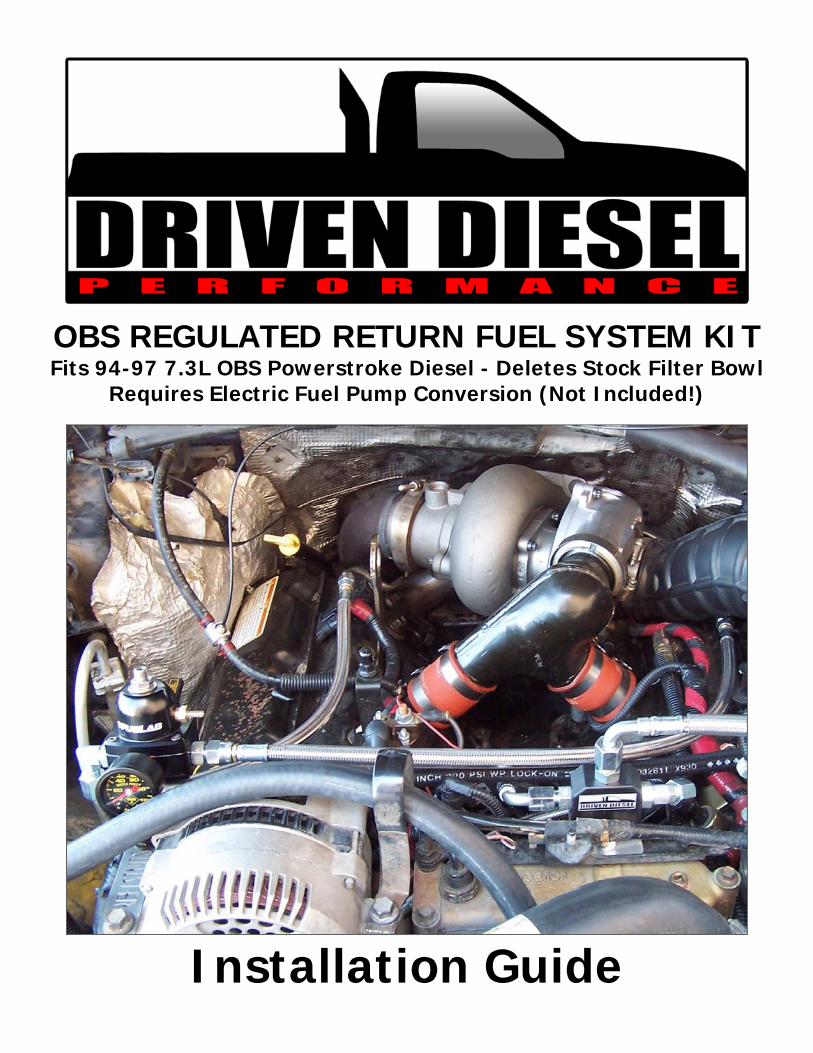
OBS REGULATED RETURN FUEL SYSTEM KIT Fits 94-97 7.3L OBS Powerstroke Diesel - Deletes Stock Filter Bowl
Requires Electric Fuel Pump Conversion (Not Included!)
Installation Guide

Last Updated: 4/11/2014 Page 1 of 13 © S Diesel, LLC
hank You for purchasing the Driven Diesel OBS Regulated Return fuel system kit! Please thoroughly read and familiarize yourself with this manual before proceeding with the installation of the kit. Also, always work safely. Make sure that there is plenty of light
and adequate ventilation, and allow yourself several hours to complete the installation. After reading these instructions, if you feel that the installation is beyond your capability, please have this kit installed by a qualified mechanic. Finally, the installation of this kit requires exposing the fuel system. Diesel fuel is flammable, and its vapor is explosive; therefore common sense dictates that there be no smoking or open flame within 50 feet of the workspace. If any fuel spills, contain it and wipe it up immediately. Do not let the fuel stand on any painted surfaces of your vehicle, or damage to the finish may occur. We HIGHLY RECOMMEND having an appropriate fire extinguisher close by!
Please don’t hesitate to contact us should you have any questions.
Driven Diesel 7.3L “Old Body Style” Regulated Return Kit Contents Please use the following parts list and pictures to become familiar with this kit. ALL of the parts listed below should be contained in your kit. We will refer to the different fittings by their part number throughout the installation. Qty: Part Number: Description:
1 73FS-OBS-DSR-TUBE Driver Side OBS Return (Rear) Tube Assembly 1 73FS-OBS-DSR-HOSE Driver Side OBS Return (Rear) Hose Assembly 1 73FS-PSR-TUBE Passenger Side Return (Rear) Tube Assembly 1 73FS-OBS-PSR-HOSE Passenger Side OBS Return (Rear) Hose Assembly 1 73FS-OBS-PSF-HOSE Passenger Side OBS Feed (Front) Hose Assembly 1 73FS-OBS-DSF-HOSE Driver Side OBS Feed (Front) Hose Assembly 1 73FS-BLOWDOWN Regulator Blowdown Line 1 73FS-REG-ASSY Regulator Assembly (with Fittings) 1 73FS-OBS-FBD-ASSY Driven Diesel OBS Fuel Bowl Delete Block w/Bracket 1 73FS-HW-PACK Hardware Pack (Fittings, Screws, Etc.) 1 73FS-REG-BRACKET S.S. Regulator Mounting Bracket 1 Gauge Liquid Filled Pressure Gauge (not installed…see special insert)
Hardware Pack Contents: 2 02MP-06MJ 1/8” Male Pipe to -06 Male JIC – Straight Fittings 1 02MP-06MJ45 1/8” Male Pipe to -06 Male JIC – 45° Fitting 1 02MP-06MJ90 1/8” Male Pipe to -06 Male JIC – 90° Fitting 1 OBS-FPlug Steel Freeze Plug 1 M8 Nylok M8-1.25 Stainless Steel Nylok Nut 1 02MP-Plug 1/8” Male Pipe Plug 1 Ped-ORing Set of Top and Bottom Turbo Pedestal O-Rings
Note: Installation of this kit requires the removal of your turbocharger. If you have been planning on replacing or upgrading your turbocharger, doing it during the installation of this kit will save you some labor time!
T

Last Updated: 4/11/2014 Page 2 of 13 © S Diesel, LLC
FUEL SYSTEM PARTS IDENTIFICATION
Hoses: (left to right)
73FS-OBS-DSR-HOSE 73FS-OBS-PSR-HOSE 73FS-OBS-DSF-HOSE 73FS-OBS-PSF-HOSE
Tubes:
73FS-PSR-TUBE (left) 73FS-OBS-DSR-TUBE (right)
Fittings:
(left to right)
02MP-06MJ (x2) 02MP-06MJ90 (x1) 02MP-06MJ45 (x1)
Use the above diagram to identify the different hoses and fittings in the kit
Some of the Basic Tools Needed for Installation:
Standard Combination Wrench Set Metric Combination Wrench Set
3/8” Drive Metric Socket Set 1/4” Drive Metric Socket Set T-27 Torx Driver or Bit ½” Drive Breaker Bar
Screw Driver Set 5/16” & 3/8” Fuel Line Quick Disconnect Tools “Allen” Wrench Set Penetrating Oil

Last Updated: 4/11/2014 Page 3 of 13 © S Diesel, LLC
Let The Fun Begin!
1. Apply penetrating oil to the turbo flange bolts (4), the exhaust up-pipe bolts/nuts at the exhaust manifolds (4) and the fuel system fittings at each end of the cylinder heads (4 total). You might even consider doing this the night before starting the work and then again before moving on to the next steps to give it ample time to work.
2. Drain Fuel Filter Bowl into a suitable container. The drain valve is yellow and is located on the front corner of the filter bowl near the glow plug relay; the drain outlet is a tube located near the passenger side bottom front of the engine. It’s usually easiest to slide an extension hose up the drain tube so it reaches the container and doesn’t’ make a mess.
3. Completely Disconnect both batteries (negative cables first, then positive) using an 13mm socket or wrench. TIP: Write down your radio stations first.
4. Using a ½” drive breaker bar or long handled ratchet, loosen the accessory belt tensioner and lift the serpentine belt off of the alternator and A/C compressor. The belt does not need to be removed completely.
5. Using a 5/16” nut driver or socket, loosen the hose clamps on the intake manifold to intake plenum couplers. Also loosen the v-band clamp holding the intake manifold to the turbocharger compressor discharge. Remove the intake manifold, couplers and clamps and set aside.
6. IMPORTANT: Use shop rags or tape to cover the openings in the intake plenums!!!
7. Using an 11mm socket, disconnect the clamp holding the downpipe to the turbocharger outlet.
8. Locate the fuel return line on the driver side rear of the fuel filter bowl (see Top Right Photo for reference). Loosen the hose clamp and remove the return hose from the fuel bowl fitting.
9. Loosen clamps and remove fuel pump and fuel filter feed hoses. These are located down in the valley, behind the fuel filter bowl. You can also just cut these hoses in half if you would prefer, they will not be reused (See Middle Right Photo for reference).
10. Disconnect cylinder head return hoses from the fuel filter housing using a 9/16” wrench (see Bottom Right Photo for reference).
11. Disconnect the water in fuel sensor at the bottom rear of the filter housing and remove the 8mm bolt (or T-25 Torx) holding the harness on the housing.
RETURN LINE
PUMP AND FILTER FEED HOSES
CYLINDER HEAD RETURN LINES

Last Updated: 4/11/2014 Page 4 of 13 © S Diesel, LLC
12. Locate the (2) 13mm bolts at the lower rear corners of the fuel filter housing and remove.
13. If you have not already, close the fuel filter housing drain valve. There will still be other places for fuel to leak out, but no point in making it easier to make a mess than necessary.
14. Carefully lift the fuel filter bowl out of the engine valley. There are still hoses and electrical connections that need to be disconnected as the assembly comes out. Once everything is disconnected, completely remove the fuel filter housing and set it aside. The filter bowl will NOT be going back into the truck, but the wiring harness that you had to disconnect to remove it will need to be reinstalled…make sure you don’t lose it!
Now we need to remove the turbocharger, alternator and A/C compressor to make room to finish removing the fuel pump and start installation of your new Driven Diesel Regulated Return Fuel System kit.
15. Remove the (2) 13mm bolts at the top of the turbocharger inlet flange.
16. Remove the (2) 15mm nuts at the bottom of the turbocharger inlet flange. You may need to use a closed end wrench with a pry bar to break these free due to the location. You may also find it helpful to use a bungee cord to hold the downpipe away from the turbocharger outlet for additional clearance. There is a bracket with a stud on the driver side of the turbocharger that will need to be slightly bent back for clearance as well.
17. It is now time to remove the turbocharger pedestal bolts. The front (2) bolts will be relatively easy to remove. The rear (2) bolts can be tricky to reach. We have found that the use of a QUALITY ¼” ratchet, extensions (6” long and 2” long) and 10mm swivel socket (see Photo at right for reference) will work well for this task. You may need a magnet to get the bolts out once you have loosened them. Note: Be aware that cheap sockets will probably break, the bolts are usually tight and we’ve broken many sockets getting them out…even the good Snap-On ones.
18. Unplug the electrical connector from the exhaust backpressure solenoid.
19. The turbocharger will now come out, with the pedestal attached.
20. Now would be a good time to clean the engine valley as we will be removing the stock fuel pump and exposing the camshaft pump drive lobe in the next steps.
21. Locate the (2) metal fuel lines leaving the rear of the stock fuel pump and running back to the rear of the cylinder heads. Using a 9/16” wrench, disconnect the fuel lines from the fittings at the rear of the cylinder heads.
NOTE: Read the next few steps carefully before proceeding!
22. Remove the (2) 10mm bolts holding the fuel pump to the engine valley. The pump is now only held in by the fit of the sealing o-ring.
23. CAREFULLY walk the pump straight up using a pry bar or heel bar (a little in the front, then back, then front and so on). Once the o-ring is out of the bore in the block the pump will lift right out.

Last Updated: 4/11/2014 Page 5 of 13 © S Diesel, LLC
24. CAUTION! The plunger in the bottom of the pump is only held in by the fit of an o-ring. It is not uncommon for that o-ring to be worn and the plunger fit to be loose. The plunger can fall out when removing the pump from the engine. Once the pump is removed, make sure the plunger is still in place.
25. To prevent crankcase contamination, we need to plug the pump drive hole in the block before moving on. Use a clean shop towel to clean the inside of the pump drive hole and the area surrounding it.
26. Locate the new freeze plug in the hardware pack and a socket (we prefer ½” drive) that just barely fits down inside the freeze plug.
27. Lightly coat the outside edge of the freeze plug with a sealant of your choice (gasket maker, loctite, etc). Use the socket and a hammer to drive the freeze plug into the open port in the engine valley. We usually prefer to use a short extension on the socket. Drive the freeze plug in just slightly past flush (see Photo at right for reference).
28. Loosen the exhaust manifold to exhaust up-pipe bolts, this will allow the up-pipe assembly to lean back against the firewall and make the work at the rear fitting on the driver side easier.
29. Before removing the rear fuel port fittings, clean thoroughly around them with brake clean or similar. Blow the area off with shop air. This will help prevent contamination of the fuel rail.
30. Using a 9/16” shallow socket and short extension, remove the fuel inlet fitting at the rear of the passenger side cylinder head. Take care not to apply a sideways load on the fitting, it can be very difficult to remove the threads if the fitting breaks.
31. There are (2) different styles of fitting in the fuel inlet port at the rear of the driver side cylinder head. Early trucks have a 2-piece fitting (shown in the photo at right), and later trucks have a 1-piece fitting. Before proceeding, using a marker or scribe, make a mark the exhaust up-pipe on either side of the fitting in the area shown in the photo.
a. If you have the 2-piece fitting, remove upper piece first and then remove the lower piece from the cylinder head.
b. If you have the 1-piece fitting, you may be able to use a pry bar against the exhaust up-pipes to make enough room to remove it or you may have to cut the fitting to get it out. If you have to cut the fitting, we recommend holding a clean shop rag over the rear fuel port and blowing some shop air through the front fuel port to blow out any debris that may have entered during the cutting operation.
FUEL PUMP PLUNGER
MARK HERE

Last Updated: 4/11/2014 Page 6 of 13 © S Diesel, LLC
32. Disconnect and remove the alternator using a 10mm socket on the electrical connector and 13mm socket on the mounting bolts.
33. Disconnect both electrical connectors from the Air Conditioning compressor. Loosen and remove the 4 mounting bolts that hold the compressor in place using a 10mm socket and ratchet. Lift the compressor off the bracket and lay it off toward the driver side fender. Use a bungee cord to hold it out of the way (see photo at right).
34. Loosen the (4) retaining bolts for the Power Steering/Air Conditioning Compressor Bracket. Loosen all but the bottom bolt completely, leave the bottom bolt threaded in some to keep the bracket aligned and ease reinstallation of the other bolts later.
35. Using a 9/16” wrench, loosen and remove both front fuel lines from the front cylinder head fuel fittings. It may be necessary to remove the EBV tube (5/8” wrench) to get the wrench on the passenger side fuel line.
36. Before removing the front fuel port fittings, clean thoroughly around them with brake clean or similar. Blow the area off with shop air. This will help prevent contamination of the fuel rail.
37. Using a ½” ratcheting wrench or deep socket, remove the driver side front fuel port fitting. Take care not to apply a sideways load on the fitting, it can be very difficult to remove the threads if the fitting breaks.
38. Remove the 90° passenger side front fitting. This may require multiple tools (7/16” wrench, larger box end wrench over the end of the fitting, screwdriver inserted in the end of the fitting). This area is a bit tight to work in, be patient.
39. Locate the (2) fuel line quick disconnect fittings at the driver side lower front corner of the engine, behind the lower radiator hose. Disconnecting these will require a 5/16” and 3/8” quick disconnect tool. These can generally be found at your local auto parts store. There is a 13mm bolt clamping the hard lines to the front of the block in the same area, remove it now as well.
40. Remove the 10mm bolt from the fuel line clamp in the engine valley, on the driver side of the high pressure oil pump. The factory steel fuel lines running up the front of the engine block can now be removed.
Disassembly is finally complete, next we will begin installation of your new Driven Diesel OBS Regulated Return fuel system kit.
NOTE: When installing tapered pipe thread fittings in pipe thread ports, DO NOT FORCE them into the desired position…this can lead to cracking the port! If you are using Teflon Tape and it gets tight in the wrong position, you will need to use more or less Teflon tape to get it oriented properly. More tape will obviously stop the rotation sooner, less will let it rotate more. Always clean off the old Teflon tape before applying fresh tape.
Also, the DRIVER SIDE REAR and PASSENGER SIDE FRONT fuel ports are NOT straight (perpendicular to the surface). The fittings will go in at an angle that “looks” like they are cross-threading…this is normal.

Last Updated: 4/11/2014 Page 7 of 13 © S Diesel, LLC
41. Locate the (4) cylinder head fittings: (2) Straight, (1) 45° and (1) 90°.
42. Apply your preferred sealant to the tapered pipe thread end of these fittings. We’ve had good luck with Loctite thread sealant, Rectorseal #5 and Teflon tape…use whatever you are most comfortable with.
43. Install the straight fittings into the DRIVER SIDE FRONT and PASSENGER SIDE REAR cylinder head fuel ports. Tighten them until firmly snug, but do not overtighten.
44. Install the 45° in the PASSENGER SIDE FRONT cylinder head fuel port. Position this fitting so it is pointing STRAIGHT UP once tightened (as shown in the photo to the right).
45. In a previous step you marked the exhaust up-pipe flange. While not every truck will need the flange clearanced in the area marked, it wouldn’t hurt to do so now so you don’t have to remove the fitting and do it at a later time if your truck is one that needs it. We recommend placing masking tape over the open fuel port and using a dremel tool to make a 1” wide “notch” that is roughly as tall as the fitting being installed. Generally the clearance needed is minor, 1/16-1/8” deep should be more than enough. RE-CLEAN THE AREA BEFORE REMOVING THE TAPE FROM THE FUEL PORT.
46. Install the 90° fitting in the DRIVER SIDE REAR cylinder head fuel port. Position this fitting so it is pointing forward at about a 30-40° angle. Use the 73FS-OBS-DSR-TUBE and the photos at right to make the final adjustment in the position of the fitting.
47. Once the DRIVER SIDE REAR fitting is properly adjusted, the 73FS-OBS-DSR-TUBE can be positioned and tightened as shown in the photos at right.
48. Install the 73FS-PSR-TUBE onto the fitting at the PASSENGER SIDE REAR fuel fitting. Position as shown in the photo at right and tighten.
49. If you removed the exhaust backpressure tube in step 35, it should be reinstalled now.
50. Locate and loosely install the 90° end of the 73FS-OBS-PSF-HOSE onto the PASS. SIDE FRONT fuel fitting. Use the photo at top right for reference.

Last Updated: 4/11/2014 Page 8 of 13 © S Diesel, LLC
51. Locate and loosely install the 45° end of the 73FS-OBS-DSF-HOSE onto the DRIVER SIDE FRONT fuel fitting. Use the photo at right as a reference.
52. Install the fuel bowl delete block and bracket assembly as shown in the photo below, using the supplied nylok nut and a 13mm socket and ratchet. You may have to move the wiring harness out of the way to access the stud, be sure to replace the harness once the nut is tightened.
53. Loosely connect the fuel feed hoses to the fuel bowl delete block as shown in the photo at right. The PASSENGER SIDE feed hose should pass in front of the DRIVER SIDE feed hose.
54. Move the hose ends and the 45° fitting on the fuel bowl delete block until the hoses are not rubbing on any components that will damage them. Tighten the jam nut on the 45° fitting and then tighten both ends of both hoses securely.
55. Install the Fuelab fuel pressure regulator onto the regulator mounting bracket. Do NOT install the fuel pressure gauge or electric sending unit (if applicable) yet.
56. Set the alternator back onto its bracket and reinstall the single inside mounting bolt with the heater hose guide bracket.
57. Reconnect the alternator electrical connections, but do not clip the wiring harness to the alternator body.
58. Lay the regulator mounting bracket over the outer alternator mounting holes and install and tighten the mounting bolts.
59. At this time, the fuel pressure gauge or electric sending unit can be installed. These are pipe threads and will require a sealant.
60. Using the photos at the top of the next page as a guide, install and tighten the 73FS-OBS-DSR-HOSE and the 73FS-OBS-DSR-HOSE. To prevent damage to the hoses, use a backup wrench on the brass nuts on the straight hose ends if the hose twists while tightening.

Last Updated: 4/11/2014 Page 9 of 13 © S Diesel, LLC
61. Once the hoses are installed and positioned, tighten the jam nut on the 90° fitting on the passenger side of the fuel pressure regulator.
62. Position the 90° fitting on the bottom of the fuel pressure regulator so it is pointing straight at the driver side of the truck and tighten the jam nut.
63. Locate the 6’ length of Gates LOC hose, straight hose end, 45° hose end and the black aluminum quick disconnect adapter fitting. These will be used to construct your fuel return line.
64. Carefully hold the 45° hose end in a vice, with the barbed end sticking up, and firmly press the LOC hose onto the barb until it seats against the yellow disc.
65. Using the picture at right, locate the factory return tube above the frame, behind the driver side front shock tower. If you have not done so already, remove the factory quick disconnect hose from this tube and discard. FIRMLY seat the black quick disconnect adapter onto this tube, you should hear it “click” into place.
66. Loosely install the 45° hose end onto the black quick disconnect adapter and orient it such that it is directing the hose AWAY FROM the steering shaft and exhaust heat. Route the hose up the inner fender, behind the A/C compressor and to the 90° fitting on the bottom of the fuel pressure regulator. With the straight hose end loosely installed on the bottom fitting of the fuel pressure regulator, determine how much of the Gates hose to trim off for a nice, clean installation. Make sure you leave a little slack for servicing the system if needed
67. Firmly press the straight hose end into the freshly cut return hose, up to the yellow disc. Install the hose end onto the 90° fitting on the bottom of the regulator and tighten. Tighten the 45° hose end onto the quick disconnect adapter at the other end of the hose and make sure that the quick disconnect adapter is properly seated on the return line.

Last Updated: 4/11/2014 Page 10 of 13 © S Diesel, LLC
68. Locate the wiring harness removed from the fuel filter during step 14. Reconnect this harness to the main engine harness and to the injection pressure regulator (IPR), which is located at the lower driver side corner of the high pressure oil pump. The connectors for the fuel heater, water in fuel sensor and the restriction switch can be left disconnected, it would not be a bad idea to tape them up to prevent possible shorts.
69. Locate the 73FS-BLOWDOWN line. Connect the line to the brass nipple in the top half of the fuel pressure regulator. Route and secure this line, avoiding heat sources that could damage it, so that the other end is under the truck and is pointing down at the ground. See #2 on the Troubleshooting Page for details.
This is the point where the feed line needs to be connected to the top of the fuel bowl delete block. The port is a standard #6 Male AN/JIC fitting. Because we cannot anticipate every different possible fuel pump setup our customers will use with this kit, we have to leave this connection up to you at this point. Follow the instructions for whatever electric fuel pump setup you will be using. Proceed with the next steps once you have completed the fuel supply connection.
70. Reconnect the batteries, positive terminal first, and then negative.
71. Cycle the ignition key or manually power up your electric fuel pump. Check the pressure gauge on the regulator and adjust the fuel pressure using the top center allen screw adjuster until 65psi of pressure is reached. Tighten the jam nut on the fuel pressure regulator adjustment screw.
72. With the fuel pump running, thoroughly inspect every fitting, tube and hose connection for any signs of fuel leakage. If any leaks are found, disable the fuel pump and resolve the leak then re-test for leaks. Do not move on to the next step until any/all leak issues have been resolved.
73. Once any leaks have been resolved, reverse the disassembly process and reinstall the power steering/air conditioning compressor bracket, air conditioning compressor, turbocharger, up-pipes, intake manifold, etc. The only remaining “old parts” once everything is back together should be the original fuel filter bowl and it’s mounting hardware, the original mechanical fuel pump and it’s mounting hardware, the original fuel lines and the mounting clamps and bolts for the original fuel lines.
CONGRATULATIONS! You’ve just completed the installation of the
Driven Diesel 7.3L OBS Regulated Return Fuel System Kit!

Last Updated: 4/11/2014 Page 11 of 13 © S Diesel, LLC
Common Fuel System Issues – Troubleshooting Guide
If you run into any problems after the installation of your fuel system, please check this page for guidance before calling your dealer or Driven Diesel for help. The issues below represent the most common causes for technical support calls.
1. THE REGULATOR MUST BE BROKEN – PRESSURE IS LOWER THAN DESIRED – This is a multi-part problem, but the first thing you need to know is that if you don’t have fuel spraying out of the hose connected to the brass nipple in the top half of the regulator, the regulator is NOT broken and is working fine. The fuel pressure regulator supplied with our kits is extremely simple, and the ONLY failure we have ever seen, since we started building fuel systems in 2001, has been a punctured diaphragm…which will leak fuel from the brass nipple. See below for some specific examples of where to look for your fuel pressure problem:
a. AIRDOG II – If you have an AirDog II (DF-165) pump that has replaced your factory fuel pump, you will need to adjust the fuel pressure at the pump. The ADII pumps are delivered from the manufacturer with the internal regulator set at 55psi. There is an adjuster screw / jam nut at one end. It is best to adjust the DRIVEN DIESEL fuel pressure regulator up (clockwise) several turns past the max pressure, THEN have someone adjust the ADII pressure adjuster until the DRIVEN DIESEL gauge shows about 70-75psi. Finally, adjust the DRIVEN DIESEL regulator down to 60-65psi. This will leave you with about 5-10psi of “overhead” pressure, which will help keep the pressure at the desired level when you are heavy on the throttle and the injectors are using more fuel from the rails.
b. FASS – If you have a high pressure FASS pump and are only getting 50-55psi at the Driven Diesel fuel pressure regulator, you will need to get the Driven Diesel 75psi FASS spring. High Pressure FASS pumps are delivered with a 55psi regulator spring, a higher pressure spring is needed to reach the desired 60-65psi of pressure.
c. OTHER FUEL PUMP – If you are running a stock fuel pump, or another “100% Duty Cycle” pump that doesn’t have an integrated fuel pressure regulator (Fuelab Prodigy, Aeromotive A1000, etc), and you are still having fuel pressure problems, you need to check you plumbing for restrictions in the inlet line to the fuel pump (causing the pump to not be able to efficiently get fuel from the tank), and you may need to have your fuel pump checked for proper operation. Low fuel pressure is caused by a lack of fuel volume from the pump, you need to determine why the volume of fuel being moved by your pump is not adequate. Pumps like the Fuelab Prodigy and Aeromotive A1000 REQUIRE a minimum of 5/8” fuel supply line between the fuel tank and the pump inlet, and any filters on the inlet side of the pump need to support high flow rates with low pressure drop across the filter.
2. FUEL LEAKING FROM BRASS NIPPLE OR POLY TUBING UNDER TRUCK – The brass nipple in the top half of the fuel pressure regulator is a “boost reference port”. This is used to increase fuel pressure as boost increases…IN GASOLINE APPLICATIONS! We do NOT use this port in diesel applications because it poses serious risk of a “runaway” situation should the diaphragm in the regulator fail. Instead, we run a long piece of poly tubing from this port to a location under the truck, to make sure that fuel is not sprayed all over the engine in the event of a diaphragm puncture. In the event of a punctured diaphragm, contact us at 623-582-4404 to purchase a replacement.

Last Updated: 4/11/2014 Page 12 of 13 © S Diesel, LLC
S DIESEL, LLC (dba STRICTLY DIESEL AND/OR DRIVEN DIESEL*) WARRANTY AND LIABILITY POLICY
MANY OF THE PRODUCTS SOLD BY S DIESEL, LLC, ARE DESIGNED TO INCREASE VEHICLE PERFORMANCE…USE AT YOUR OWN RISK!
Do not install or use any product(s) purchased from S DIESEL, LLC (“S DIESEL”)
until you have carefully read the following Warranty and Liability Policy (the “Warranty”).
PRODUCT WARRANTY POLICY Subject to the limitations, exclusions, and qualifications set forth below, the product or the products made and sold by S DIESEL (the "S Diesel Product" or "S Diesel Products") are warranted to Buyer as set forth in this Warranty. The installation of the S Diesel Products indicates that Buyer has read, understands and agrees to the terms and conditions of this Warranty. Any warranty on products that are made by another manufacturer which are resold by S DIESEL to Buyer is made to Buyer by the manufacturer of such products in accordance with and subject to all conditions and limitations of the manufacturer's warranty in effect on the date of the purchase by Buyer. S DIESEL makes no warranties to Buyer, express or implied, with respect to such products that are made by another manufacturer. LIMITED WARRANTY The S Diesel Products (except S Diesel Products specified to have different warranty terms) are warranted to be free from defects in material and workmanship, under normal use and service for a period (the “Product Warranty Period”) of ninety (90) days from date of delivery to Buyer, unless S DIESEL performs the work installing the S Diesel Products, in which case the Product Warranty Period shall be extended to equal the Service Warranty Period (as defined below under “SERVICE WARRANTY POLICY”). S DIESEL’s liability under this Warranty is limited to repair or replacement at its option, subject to the provisions set forth herein, of any S Diesel Products which upon examination S DIESEL are found to be defective. Buyer shall prepay cost of transportation of defective S Diesel Products to S DIESEL for inspection. S DIESEL shall not have any responsibility under this Warranty unless (1) the defect in an S Diesel Product results in a claim arising within the Product Warranty Period, measured from the date of delivery to Buyer, (2) the S Diesel Product, if installed by an installer other than S DIESEL, was properly installed, (3) the S Diesel Product was normally maintained and not subject to misuse, negligence or accident, and (4) the S Diesel Product, system components and/or accessories were not repaired or altered in such a way that in the judgment of S DIESEL the S Diesel Product’s performance or reliability was adversely affected. EXCLUSIONS Any of the above warranties by S DIESEL shall not apply if Buyer’s vehicle is in an accident, misused, neglected, altered from the S Diesel Product’s manufacturer original designs or specifications or serviced in connection with a warranty claim hereunder without prior written approval of S DIESEL. REMEDIES EXCLUSIVE Repair or replacement of defective S Diesel Products in accordance with the Limited Warranty above shall be Buyer’s exclusive remedy for and shall constitute satisfaction of any and all liabilities of S DIESEL with respect to any defect in any S Diesel Product whether based in warranty, contract, tort, negligence, strict liability or otherwise. DISCLAIMERS AND LIMITATIONS THE EXPRESS WARRANTIES SET FORTH ABOVE ARE EXCLUSIVE AND IN LIEU OF ALL OTHER WARRANTIES, CONDITIONS AND TERMS AS TO QUALITY OR FITNESS OF ALL PRODUCTS SUPPLIED BY S DIESEL TO BUYER, WHETHER WRITTEN, ORAL OR IMPLIED, STATUTORY OR OTHERWISE, INCLUDING WITHOUT LIMITATION, ANY WARRANTIES OR CONDITIONS OF MERCHANTABILITY OR FITNESS FOR A PARTICULAR PURPOSE, AND ALL SUCH OTHER WARRANTIES, CONDITIONS AND TERMS ARE HEREBY DISCLAIMED AND EXCLUDED BY S DIESEL. IN NO EVENT SHALL S DIESEL BE LIABLE FOR ANY LOSS OF ACTUAL OR ANTICIPATED PROFITS, LOSS OF ANTICIPATED BUSINESS, COST OF SUBSTITUTE PRODUCTS, LOSS OF USE OR DOWNTIME COSTS OR DELAY CLAIMS (WHETHER DIRECT OR INDIRECT) NOR FOR ANY OTHER SPECIAL, INDIRECT, INCIDENTAL OR CONSEQUENTIAL DAMAGES ARISING OUT OF OR RELATING TO THIS WARRANTY OR THE SUPPLY OF S DIESEL PRODUCTS TO BUYER, WHETHER BASED IN WARRANTY, CONTRACT, TORT, NEGLIGENCE, STRICT LIABILITY OR OTHERWISE. BUYER ACKNOWLEDGES THAT (A) THE PRODUCTS PURCHASED FROM S DIESEL WILL BE USED IN CONNECTION WITH ACTIVITIES, UNDER EXTREME CONDITIONS AND/OR SUBJECT TO MODIFICATIONS REQUESTED BY BUYER FOR WHICH THE PRODUCTS MAY OR MAY NOT BE SUITABLE; (B) THE WARRANTY OF SUCH PRODUCTS FOR PERFORMANCE IN CONNECTION WITH SUCH ACTIVITIES, UNDER SUCH EXTREME CONDITIONS AND/OR SUBJECT TO SUCH MODIFICATIONS REQUESTED BY BUYER IS NOT POSSIBLE; AND (C) ANY MANUFACTURER’S WARRANTY MAY BE VOIDED BY USE OF THE PRODUCTS IN CONNECTION WITH SUCH ACTIVITIES, UNDER SUCH EXTREME CONDITIONS AND/OR SUBJECT TO SUCH MODIFICATIONS REQUESTED BY BUYER. BUYER ACKNOWLEDGES THAT THE INSTALLATION OF ANY S DIESEL PRODUCTS THAT ARE NOT LEGAL FOR USE ON POLLUTION CONTROLLED MOTOR VEHICLES IS DONE SOLELY AT THE REQUEST OF BUYER AND ALL RESPONSIBILITY FOR ANY EFFECTS ON THE ORIGINAL VEHICLE MANUFACTURERS WARRANTY, ABILITY TO PASS ANY EMISSIONS INSPECTIONS OR FOR ANY FINES THAT MAY OCCUR DUE TO THE REMOVAL OF FEDERALLY MANDATED EMISSION CONTROL EQUIPMENT IS ON BUYER. No employee or representative of S Diesel has the authority to make any representation, promise or agreement which in any way varies from the terms and conditions of this Warranty. No suit or claim based on any cause of action, regardless of form, arising out of or relating to this Warranty or any of the S Diesel Products supplied by S DIESEL may be brought by Buyer or anyone claiming by, through or under Buyer against S DIESEL more than one year after the date that such cause of action arose. IN THE EVENT BUYER DOES NOT AGREE WITH THE TERMS AND CONDITIONS OF THIS WARRANTY, BUYER MAY PROMPTLY RETURN THE PRODUCT TO S DIESEL FOR A FULL REFUND. THE PRODUCT MUST BE IN NEW, UNUSED AND RESELLABLE CONDITION, BE RECEIVED WITHIN FIFTEEN (15) DAYS OF THE ORIGINAL PURCHASE AND BE ACCOMPANIED BY A DATED PROOF OF PURCHASE (RECEIPT). PRODUCTS RETURNED IN NEW, UNUSED AND RESELLABLE CONDITION WILL NOT BE SUBJECT TO ANY RESTOCKING FEES.

Last Updated: 4/11/2014 Page 13 of 13 © S Diesel, LLC
THE INSTALLATION OR USE OF ANY PRODUCT PURCHASED FROM S DIESEL INDICATES THAT BUYER HAS READ, UNDERSTANDS AND AGREES TO THE TERMS AND CONDITIONS OF THIS WARRANTY.
SERVICE WARRANTY POLICY
Subject to the limitations, exclusions, and qualifications set forth below, the service or services performed by S DIESEL (the "S Diesel Service" or "S Diesel Services") are warranted to Buyer as set forth in this Warranty. LIMITED WARRANTY The S Diesel Services (except S Diesel Services specified to have different warranty terms) are warranted to have been performed in a workmanlike manner and to hold up under normal use and service for a period (the “Service Warranty Period”) of twelve months from date the S Diesel Services are performed or twelve thousand miles from the documented odometer reading at the time the S Diesel Services are performed, whichever occurs first. S DIESEL’s liability under this Warranty is limited to replication, subject to the provisions set forth herein, of any S Diesel Services which upon examination S DIESEL are found to have not been performed in a workmanlike manner. S DIESEL shall not have any responsibility under this Warranty unless (1) the defect in an S Diesel Service results in a claim arising within the Service Warranty Period, measured from the date the S Diesel Service is performed, (2) the vehicle upon which the S Diesel Service was performed was normally maintained and not subject to misuse, negligence or accident, and (3) the vehicle upon which the S Diesel Service was performed was not repaired or altered in such a way that in the judgment of S DIESEL the S Diesel Service’s durability was adversely affected. EXCLUSIONS Any of the above warranties by S DIESEL shall not apply if Buyer’s vehicle is in an accident, misused, neglected, or serviced in connection with a warranty claim hereunder without prior written approval of S DIESEL. REMEDIES EXCLUSIVE Replication of unsatisfactory S Diesel Services in accordance with the Limited Warranty above shall be Buyer’s exclusive remedy for and shall constitute satisfaction of any and all liabilities of S DIESEL with respect to any defect in any S Diesel Service whether based in warranty, contract, tort, negligence, strict liability or otherwise. WITHOUT LIMITING THE FOREGOING, IN NO EVENT SHALL S DIESEL BE LIABLE FOR ANY LOSS OF ACTUAL OR ANTICIPATED PROFITS, LOSS OF ANTICIPATED BUSINESS, COST OF SUBSTITUTE SERVICES, LOSS OF USE OR DOWNTIME COSTS OR DELAY CLAIMS (WHETHER DIRECT OR INDIRECT) NOR FOR ANY OTHER SPECIAL, INDIRECT, INCIDENTAL OR CONSEQUENTIAL DAMAGES ARISING OUT OF OR RELATING TO THIS WARRANTY OR THE PERFORMANCE OF S DIESEL SERVICES FOR BUYER, WHETHER BASED IN WARRANTY, CONTRACT, TORT, NEGLIGENCE, STRICT LIABILITY OR OTHERWISE.
GENERAL PROVISIONS APPLICABLE TO BOTH PRODUCT AND SERVICE WARRANTIES
ASSIGNABILITY OF WARRANTY This Warranty is for the exclusive benefit of Buyer and is not assignable. WARRANTY CLAIMS PROCEDURE Warranty claim forms can be printed from the company websites (http://www.drivendiesel.com (Products) and http://www.strictlydiesel.com (Services)). A properly completed warranty claim form and a copy of the invoice for any defective Product or Service must be received by the Seller within the earlier of 30 days after the expiration of the Warranty Period or the incident giving rise to the claim. To qualify for an adjustment under this Warranty a defective Product must be returned prepaid to the Seller for inspection and must be accompanied by a dated proof of purchase receipt. In addition, the serial number of the defective Product, if any, must match the serial number on Buyer’s invoice. All Warranty claims are subject to approval by the Seller and/or the Product’s manufacturer. Buyer must pay all applicable service charges and taxes. Defective Products accepted for warranty compensation become the property of the Seller. To qualify for an adjustment under this Warranty a vehicle upon which S Diesel Services have been performed must be delivered to the Seller during Seller’s hours of operation for inspection and must be accompanied by a dated proof of purchase receipt. WAIVER Any failure of the part of S Diesel to insist on strict compliance with the Warranty Provisions shall no way constitute a waiver of such right. No claim or rights arising out of a breach of the Warranty Provisions by Buyer may be discharged in whole or in part by a waiver of the claim or right, unless the waiver is in writing signed by an authorized representative of S Diesel. S Diesel’s waiver or acceptance of any breach by Buyer of any provisions of the Warranty Provisions shall not constitute a waiver of or an excuse for nonperformance as to any other provision of the Warranty Provisions nor as to any prior or subsequent breach of the same provision. APPLICABLE LAW The Warranty shall be governed by the laws of the State of Arizona (excluding Arizona law with respect to conflicts of law). * Driven Diesel was formerly known as ITP Diesel, LLC and Sinister Diesel, LLC.