observation of beam orbit fluctuation with forced ... · fig. 4: comparison of reconstructed beam...
TRANSCRIPT

2nd International Workshop on Mechanical Engineering Design of Synchrotron Radiation Equipment and Instrumentation MEDSI02) September 5-6, 2002 – Advanced Photon Source, Argonne National Laboratory, Argonne, Illinois U.S.A.
Observation of Beam Orbit Fluctuation with Forced-Vibrating Magnets and Vacuum Chambers
T. Nakazato, S. Date', K. Fukami, S. Matsui, T. Magome, M. Oishi, K. Soutome, H. Tanaka, and T. Yorita
Japan Synchrotron Radiation Research Institute (SPring-8), Kouto Sayo, Hyogo 679-5198, Japan Phone: +81 (791) 58-0851; Fax: +81 (791) 58-0850
e-mail: [email protected]
Abstract
Fluctuations of the beam orbit were observed quantitatively when the quadrupole magnets and vacuum chambers were vibrated by external force. The vibration frequency spectra, amplitudes and phases, of each component were measured individually at the same time. The calculated spectra of closed orbit distortions, which were reconstructed from vibration spectra of each component with involving eddy currents in the vacuum chamber, were well agreed quantitatively with those of observed orbit fluctuation. At the frequencies of 10Hz to 1kHz, contribution of the vacuum chamber vibration to the beam fluctuation was found to be greater than those of quadrupole magnet vibration at SPring-8. Beam position stabilization at frequencies from 10 to 50Hz was dramatically improved by reducing vacuum chamber vibration with inserting supports and minimizing the flow rate of its cooling water. These results show that reducing vibration of vacuum chambers, as well as quadrupole magnets, is essential for the stabilization of beam position, or improving effective transverse emittance. It will give us a new guideline of component design for future accelerators.
Keywords: orbit stabilization, vibration, emittance, vacuum chamber
1. Introduction
The effective emittance growth due to the orbit fluctuation of the electron beam is caused by many disturbance sources at synchrotron radiation facilities. The source hunting and studies on beam orbit fluctuation mechanism are carried out for beam stabilization at SPring-8. Investigated disturbance sources are ripple of the magnet power supplies, change in line voltage due to the injector linac and synchrotron, change in temperature and mechanical vibration of the accelerator components, coherent synchrotron oscillation, and insertion devices. Each effort has obtained result to reduce the beam fluctuation. After the success in the suppression of coherent synchrotron oscillation [1], the main source is narrowed down to the mechanical vibration of the accelerator components.
The vibration issue is complicated by two senses. One is that the accelerator components have many eigen frequencies and mechanical coupling constants among them. The other is that the coupling constants between beam position and vibration of the components are not known clearly. In order to simplify and resolve these problems, the components were vibrated by external driving force with known frequency and phase, and vibration amplitude and phase at appropriate points was measured. Information of both amplitude and phase enabled us mode assignments of the vibration, analytical
147

2nd International Workshop on Mechanical Engineering Design of Synchrotron Radiation Equipment and Instrumentation MEDSI02) September 5-6, 2002 – Advanced Photon Source, Argonne National Laboratory, Argonne, Illinois U.S.A.
reconstruction of the vibration of total mechanical system, quantitative estimation of its contribution to the beam fluctuation, and comparative study with actual beam fluctuation.
In this paper we will report experimental methods, experimental results, analytical reconstruction of beam orbit fluctuation which is well agreed with the beam orbit measured by BPM, and an application with successful reduction of beam fluctuation. It is remarkable that the vibration of vacuum chambers, as well as magnets, produces a significant effect on the beam fluctuation.
2. Experimental Methods
A stack of piezo elements [2] was used for a driving device to produce vibration. (see Fig. 1). It had a maximum load of 70 kN, a maximum driving force of 50 kN, a stroke of 8 µm/1 kV, a stiffness of 3.5 kN/µm, and an eigenfrequency of 12 kHz. This device could move a quadrupole magnet, which was fixed tightly to the girder and weighed 870 kg, by 0.85 µm and 4.0 µm for vertical and horizontal direction, respectively. A driving amplifier for the piezo supplied output voltages from 0 to 1 kV and a –3 dB bandwidth of 900 Hz.
The vibration was detected by a set of three-dimensional accelometer [3], whose frequency response, sensitivity and phase rotation, was calibrated by a standard vibration source at frequencies from 1 Hz to 1 kHz. Almost flat frequency response of the accelometer was confirmed at frequencies below 600Hz and the calibration data were used for compensation of measured data. The value of acceleration was converted into the displacement length by numerical integration after measurement.
An FFT dynamic signal analyzer [4] was used to measure frequency response of the mechanical vibration and orbit fluctuation. The piezo was driven by a reference signal, or an internal signal source of this analyzer. The amplitude and phase of the signals from accelometer and BPM were measured as an amplitude ratio and a phase difference from the reference signal. The reference frequencies were swept from 1 Hz to 1 kHz and the Bode diagram of the vibration was obtained automatically. Although the effective noise bandwidth was +/-10% of the measuring frequency, the frequency resolution in low noise condition was +/-2.3%, which corresponded to the sweep step of the frequency.
One of the magnet girders, named C8-A, was selected for vibration study. The piezo was set at a quadrupole magnet, named Q1, to generate reproducible vibration. Three-dimensional accelometer was set at key points such as quadrupole magnets, sextupole magnets, a magnet girder, and vacuum chambers as shown in Figs. 1 and 2. As we could not set the accelometer to the vacuum chamber at the center of the a quadrupole magnet, we evaluated the vibration at the center by the average of both upstream and downstream ends.
Three sets of button electrode BPM with bandwidth of more than 10 kHz were used to measure the beam orbit fluctuation. As the BPMs were located at the points separated form the shaking point by more than 210 m, the vibration by piezo was
148

2nd International Workshop on Mechanical Engineering Design of Synchrotron Radiation Equipment and Instrumentation MEDSI02) September 5-6, 2002 – Advanced Photon Source, Argonne National Laboratory, Argonne, Illinois U.S.A.
sufficiently attenuated at the position of BPM. Measured vibration amplitudes of the BPMs were smaller by 1/10 than those of beam fluctuation.
Fig. 1 (right): Exper-imental set up. A piezo was used to shake a magnet. A 3-D accelometer was used to measure the vibration.
le y g
Fig. 2 (below): Positions of vibration measurements. Q1~Q3 are quadrupomagnets. S1 and S2 are sextupole magnets. Al-though only Q1 was shaken bpiezo, the vibration was transmitted to all the components on the girder. A bivibration due to cooling water was found at the point shown in the picture.
149

2nd International Workshop on Mechanical Engineering Design of Synchrotron Radiation Equipment and Instrumentation MEDSI02) September 5-6, 2002 – Advanced Photon Source, Argonne National Laboratory, Argonne, Illinois U.S.A.
3. Experimental Results
An example of the horizontal vibration of a magnet and a vacuum chamber is shown in Fig. 3. The dashed line and the solid line are the vibration of Q2 and vacuum chamber in Q2, respectively. Circles and squares show vibrations without shaking, which correspond to background noise vibration. The amplitude of the vacuum chamber is about ten times as big as that of the magnet in frequencies from 10 to 100 Hz, and more than a hundred times from 100 to 1000 Hz. This result suggests, they are not magnets but vacuum chambers that dominate orbit fluctuation due to the mechanical vibration. The amplitude of the forced vibration is sufficiently bigger than the noise level at the resonant peaks. This results in the frequency resolution as same as the sweep step.
Fig. 3: Horizontal vibration of magnet (Q2) and vacuum chamber (VC).
Measured orbit fluctuations are shown as a bold solid line (with shaking) and a line with circles (without shaking) in Fig. 4. At frequencies from 20 to 100 Hz effect of shaking is observed clearly.
4. Discussion
A closed orbit distortion (COD) due to the vibrating disturbance of frequency ω can be estimated by the next formula [5].
150

2nd International Workshop on Mechanical Engineering Design of Synchrotron Radiation Equipment and Instrumentation MEDSI02) September 5-6, 2002 – Advanced Photon Source, Argonne National Laboratory, Argonne, Illinois U.S.A.
[ ]
−×
+−= ∑
)chambers for vacuum()}(1{)magnetsfor ()(
)(sin
)()(cos)()(21),( )(
ωηωη
ωθπν
ϕϕνπββω ωφ
i
i
iki
kiBPMkiBPM
iBPM
kiesssssu, (1)
where and are the positions along the reference path. The COD is measured with the BPM at s , and the i th disturbing element kicks the beam at by an angle
BPMs kis
BPM kis kiθ and in phase kiφ . β and ϕ are the betatron function and phase advance at i th
Fig. 4: Comparison of reconstructed beam vibrations (Calc.) and real beam data.
disturbance, respectively. ν is the tune number either for vertical or horizontal. iη is an attenuation factor, a complex number in general, due to the effect of the eddy current in the vacuum chamber. The η changes drastically at frequencies around which the skin depth is comparable to the thickness of the vacuum chamber wall; i.e., η approaches to unity for low frequencies or thin resistive wall chambers, the other way around it approaches to zero for high frequencies or thick conductive walls. For the quadrupole magnets and their vacuum chambers, the kick angles kiθ are given by iiki x∆= ik lθ , where and are the strength and length of the i th quadrupole magnet, respectively. The is the vibration amplitude of either magnets or chambers. Positive sign of
corresponds to focusing quadrupole, QF.
ik
ixil
∆
ik
151

2nd International Workshop on Mechanical Engineering Design of Synchrotron Radiation Equipment and Instrumentation MEDSI02) September 5-6, 2002 – Advanced Photon Source, Argonne National Laboratory, Argonne, Illinois U.S.A.
Substituting parameters of the SPring-8 Storage Ring into formula (1), we can reconstruct COD from amplitude and phase measured with forced vibration by the piezo. As a skin depth at 100 Hz for aluminum is 12.3 mm, which is comparable to the average vacuum chamber wall thickness of 15 mm, we cannot apply an asymptotic approximation to the attenuation factor. Although the cross section of the vacuum chamber has a complicated and asymmetric shape (see Fig. 1), a parallel plate model was introduced to characterize and estimate the attenuation factor.
Comparison between reconstructed COD and Measured COD is shown in Fig. 4. “Calc. (Mag. 1=η )” and “Calc. (Vac. Chamb. 0=η )” are reconstruction results for constant attenuation factor 1=η and 0=η , respectively. In the former case the magnetic field moves with a magnet, and in the latter case with a vacuum chamber. A dashed line shows the reconstructed result for parallel plates with thickness of 27 mm.
In this experimental condition, magnet vibration is dominant at the peak of 25 Hz, and vacuum chamber vibration is dominant at the peaks of 40, 100 Hz. These peaks agreed well with the measured peaks. Especially, not the magnet vibration but the vacuum chamber vibration can explain the peak at 100 Hz. This result is a proof that the eddy current, which is excited by vacuum chamber vibration, kicks the electron beam in the storage ring.
The thickness of the parallel plates was scaled so that the reconstructed peak at 25 Hz fits the measured one, and was about double of average thickness 15 mm of the vacuum chamber. As this discrepancy itself would be an evaluation of the parallel-plate-model, the other approaches such as finite element methods and/or actual measurements are being planned for more accurate estimation. We did not discuss the effects of sextupole magnets and their vacuum chambers in this paper, because field excited by eddy current in sextupole field should be canceled at the beam axis for the symmetric boundary condition. Further study for the sextupole magnets and actual vacuum chambers, which are asymmetric as shown in Fig. 1, is also scheduled at the SPring-8 magnet test bench.
The arrows in Fig. 3, labeled 0π, π/2, and π, show the vibration modes of three quadrupole magnets on the girder. These modes are assigned by the phase difference between the next neighbor magnets. As Q2 is a focusing, Q1 and Q3 are defocusing quadrupole magnets, and phase advance of betatron oscillation between them is small (8.8 deg for horizontal and 19.6 deg for vertical), the kick angles by π mode vibration are built up and closed orbit is more deformed than those by 0π and π/2 modes, i.e., the kick angles is canceled for 0π and π/2 modes. One can confirm that the reconstructed and measured amplitude for π mode in Fig. 4 is much stronger than those of the other modes.
The 0π mode and π/2 mode correspond to the parallel shift and the rotation of the girder with magnets, respectively. Although the accelerator is designed so that its beam orbit becomes insensitive to the magnet misalignment such as parallel shift and rotation, misalignment, or deformation, corresponding to the π mode is not considered in the
152

2nd International Workshop on Mechanical Engineering Design of Synchrotron Radiation Equipment and Instrumentation MEDSI02) September 5-6, 2002 – Advanced Photon Source, Argonne National Laboratory, Argonne, Illinois U.S.A.
design process. A girder design to suppress the vibration with build-up-kick is required for future accelerators.
The other arrows in Fig. 3, labeled from 1f to 7f, correspond to the harmonics of the vacuum chamber oscillation. A big peak around 100 Hz is considered to be a hybrid mode with the vertical oscillation.
5. Application
As we discussed above, effect if vacuum chamber vibration is confirmed to be significant for the beam stabilization. A vibration hunting on the vacuum chamber was carried out, and big vibration sources were found at similar place where the chamber has the same structure of cooling water system and big noise was spreading out. (See Fig. 2.)
In order to reduce the vibration the following improvements were applied to the 44 chambers and their cooling water systems at SPring-8 Storage Ring. 1) The chamber was fixed to the girder with a supporting arm. 2) The water flow rate was reduced from 8 liter/min to 4 liter/min, as small as possible. 3) Water pipes are partially sized up from 1/2” to 3/4” and smoothed at the bending corner. 4) Needle valves instead of ball valves are employed to control the water flow. The supporting arm was the most effective among them, and water flow rate was the second for the vibration suppression. The Reinolds number of the water flow in a 1/2” pipe was 18,000 and 9,000 for 8 and 4 liter/min, respectively. Both case fall within the turbulent flow region.
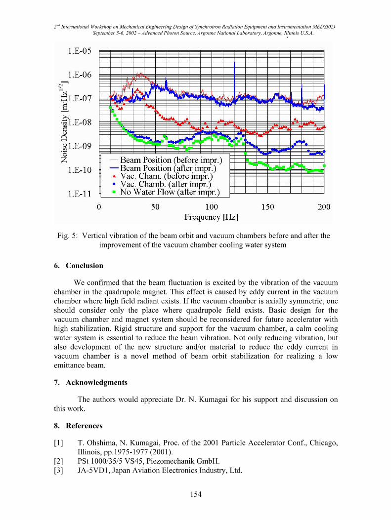
After completion of this engineering work, a dramatic calm was observed in the beam orbit signals as shown in Fig. 5. Fine and bold lines without marker show the vertical beam orbit fluctuation before and after the improvements, respectively. A drastic difference was observed at frequencies from 20 to 50 Hz, in which the amplitude of the chamber vibration was reduced. Dots show the amplitudes of vertical vacuum chamber vibration. Triangular and circular dots are before and after improvements, respectively. Square dots are without cooling water flow after improvement. The peak amplitude of the chamber vibration was reduced to 1/100 at frequency of 34 Hz, and less than 1/10 at frequencies from 25 to 50 Hz. Similar suppression of the orbit fluctuation was observed also for horizontal direction at 70 to 90 Hz by –10 dB in magnitude.
Though the vibration of the vacuum chamber lowered by one order in amplitude at 150 to 200 Hz, the orbit fluctuation did not changed in this frequencies. As the vacuum chamber vibration is dominant for orbit fluctuation in this frequency region, further upgrade of the beam quality is expected with source hunting and vibration damping. On
this frequency region, the complementary study on suppressing synchrotron oscillation is important for beam stabilization.
the other hand, as orbit fluctuation tail due to the synchrotron oscillation [1] is lying in
153
SI02)
2nd International Workshop on Mechanical Engineering Design of Synchrotron Radiation Equipment and Instrumentation MEDSeptember 5-6, 2002 – Advanced Photon Source, Argonne National Laboratory, Argonne, Illinois U.S.A. .Fig. 5: Vertical vibration of the beam orbit and vacuum chambers before and after theimprovement of the vacuum chamber cooling water system
6. Conclusion
We confirmed that the beam fluctuation is excited by the vibration of the vacuum chamber in the quadrupole magnet. This effect is caused by eddy current in the vacuum chamber where high field radiant exists. If the vacuum chamber is axially symmetric, one should consider only the place where quadrupole field exists. Basic design for the vacuum chamber and magnet system should be reconsidered for future accelerator with high stabilization. Rigid structure and support for the vacuum chamber, a calm cooling water system is essential to reduce the beam vibration. Not only reducing vibration, but also development of the new structure and/or material to reduce the eddy current in vacuum chamber is a novel method of beam orbit stabilization for realizing a low emittance beam.
7. Acknowledgments
The authors would appreciate Dr. N. Kumagai for his support and discussion on this work.
8. References
[1] T. Ohshima, N. Kumagai, Proc. of the 2001 Particle Accelerator Conf., Chicago, Illinois, pp.1975-1977 (2001).
[2] PSt 1000/35/5 VS45, Piezomechanik GmbH. [3] JA-5VD1, Japan Aviation Electronics Industry, Ltd.
154

2nd International Workshop on Mechanical Engineering Design of Synchrotron Radiation Equipment and Instrumentation MEDSI02) September 5-6, 2002 – Advanced Photon Source, Argonne National Laboratory, Argonne, Illinois U.S.A.
[4] HP35670A, Agilent Technologies. [5] This formula can be derived easily from a well known COD formula, e.g., H.
Wiedemann, Particle Accelerator Physics, Springer-Verlag 236 (1993).
155