observatory systems - asd.gsfc.nasa.gov · skin provides micro-meteroid protection two x-ray...
TRANSCRIPT

IXO Facility Science Team Meeting August 20 - 22, 2008 / NASA/GSFC
Observatory Systems
Gabriel Karpati, NASA GSFC
NASA Mission Systems Engineer
August 15, 2008 Systems Overview–2
Outline
Mission Configuration– Launch and Orbit
– Timeline
– Observation and Pointing
Observatory Configuration– Subsystems Highlights
– Resource Summary

August 15, 2008 Systems Overview–3
Mission Overview
Single Mirror Configuration– 3.3 m dia mirror with a 20 m focal length– Part of the metering structure is
extensible (12.2m)Mission Life and Sizing
– Class B Mission, no performance degradation w/ single point failure
– Mission Life: 5 years required, 10 years goal, consumables sized for 10 years
Launch – Launch on an Atlas V 551 medium fairing
from KSC on 12/2020– Throw mass ~6342 kg (w/o Payload
Attachment Fixture)– Direct launch into an L2 800,000 km
semi-major axis “zero Insertion delta-v”
halo orbit– 100 day cruise to L2
Mission Orbit – At insertion, perform a maneuver to
lower the Y amplitude to 700,000 km– Total Ionizing Dose (10 yrs):
27 kRad; severe Environment for Single Events Effects; micrometeoroid protection required
Earth- L2 Distance1.5 x 106 km
L2
Lunar Orbit
E
Earth-Sun angle between 7 and 30º
Max Range 1.8 x 10⁶ km
L2 Orbit ~700,000 km radius, ~180 day period
L2 Transfer Trajectory
To Sun
Courtesy - JWST

August 15, 2008 Systems Overview–4
Orbit ConsiderationsBaseline Orbit: 700,000 km “Y” semi-major axis L2 orbit
– Orbit mostly inside Earth’s Magnetosheath• Lower low energy particle flux (solar wind)
– No Earth shadows during length of mission at L2• Potential of lunar penumbra at < 14% obscuration
– L2-Earth-SC Angle varies from 7°
to 30°
over 10 years
Orbit type varies as a function of launch time within a dayThe greater an L2 orbit‘s amplitude, the less insertion delta-v is requiredInsertion orbit selected to maximize launch opportunities
The size of the smallest achievable “zero-insertion-delta-v”orbit is a function of launch date Frequent launch opportunities exist for “zero-insertion-delta-v” 800,000 km orbits (several opportunities every week)~1-2 launch opportunities per year for “zero-insertion-delta-v”700,000 km orbits
TTI Local Time
TTI C
oast
Tim
e Halo Orbits
Shadow Region
Lissajous Orbits
Courtesy Mark Beckman, JWST

August 15, 2008 Systems Overview–5
Mission Timeline Launch (L) at T0
– Instruments and Cryo completely deenergized, Spacecraft power in Launch Mode (low power)
– Launch Vehicle
(LV) First Stage is ballistic (falls into ocean)
Transfer Trajectory Insertion (TTI) at L + 25 to 120 minutes
– Performed by LV Second Stage
LV Separation: TTI + 5 minutes– LV 2nd stage Collision and Contamination Avoidance
Maneuver– LV separation, Observatory in Acquisition Mode; acquire
Sun-positive nominal attitude– Need live RF Comm w/ ground (have TDRSS capability)
Deploy Solar Arrays & High Gain AntennaSpacecraft full power on
– Some portions of Payload on, Cryo off
Commence Observatory CheckoutELV Dispersion Corrections at TTI + 24 hoursDeploy Metering Structure Commence Instrument Aliveness ChecksObservatory Outgas
– At least 2 weeks
First Mid-Course Correction: TTI + 16 daysInstrument internal background measurement Jettison / Open Flight Mirror Assembly Covers, turn Cryo on
Open Instrument Covers and Gate ValvesCalibrate w/ Celestial TargetsSecond Mid-Course Correction: TTI + 60 daysL2 Orbit Insertion (L2OI) / Y-Amplitude Lowering Maneuver: ~ TTI + 100 daysScience Ops
– Downlink data (while observing, 30 minutes a day)– Repoint as required– Momentum Unloading Burns and L2 Stationkeeping burns
during slews– Switch Instrument Mode every 2 weeks to 1 month
EOM Disposal: L + 10 years +++ …– Delta-v < 1 m/s to driftaway trajectory, optional (not
required)

August 15, 2008 Systems Overview–6
Observation Parameters
Field of Regard Pitch: +/- 20° off SunlineYaw: +/- 180°Roll: +/- 10° (with a goal of 20°) off Sunline
Slew Average slew: 60 degrees in 60 minutes (goal value; negotiable, based on Reaction Wheel selection) Average # of slews per day: 2.5 during first year of mission, less
later
Operational Efficiency
~85%, when averaged over the mission life
Timing accuracy Photon arrival tagged to UTC to ±100 μsec
EarthSun
Field Of Regard
Boresight stays within this +/-
20°
band at all times (20 deg yaw)
Target
Roll: +/-
10°

August 15, 2008 Systems Overview–7
Pointing Parameters
Term Definition Parameters StatImage Position Control The absolute precision of placing and
keeping an image on the Focal Plane Detector
• Pitch: 10 arcsec• Yaw: 10 arcsec• Roll: 30 arcsec
3σ
Image Position Reconstruction Knowledge(a.k.a.: “Aspect Reconstruction”)
The absolute post-facto knowledge of a down-linked and processed (calibrated, reconstructed) image’s position relative to the Truth
• Pitch and Yaw: 0.7 arcsec HPD
Jitter(excluded from the Image Position Knowledge requirements)
Jitter effects encompass all high frequency errors above the bandwidth of the Control System and Monitoring System
• 200 milliarcsec over 200 msec
HPD
Switch between Mode 1 and 2 on average 2 times per month (based on use of XMS and WFI).
Targets available for < 12 weeks per year based on ±
20 deg pitch field of regard.
Science ModesMode 1 Mode 2
Instrument Operations Science XMS, XGS WFI, HXI, XGS
Standby WFI, HXI XMS
Observation Duration Average 10 hours
Minimum 30 minutes
Peak 48 hours
Percent of time for each Mode 50% 50%

August 15, 2008 Systems Overview–8
Observatory On-orbit Configuration
IM Sunshade
Ultra Flex Solar Arrays
Optics Module Sunshade
FocusedX-ray beamfrom FMA
DispersedX-ray beamfrom XGS
Body mounted fixed Solar
Arrays
DeployableTelescope
Shroud

August 15, 2008 Systems Overview–9
Launch Configuration
Atlas V (551) Medium
Composite Fairing
Encapsulation I/F Ring
“3302”
Truss Payload
Attachment Fixture
Centaur (Atlas V’s 2nd
Stage)
Observatory in Stowed
Configuration
August 15, 2008 Systems Overview–10
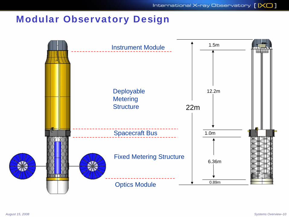
Modular Observatory Design
Fixed Metering Structure
Deployable Metering Structure
Instrument Module
Spacecraft Bus
Optics Module
22m
6.36m
0.89m
1.0m
12.2m
1.5m

August 15, 2008 Systems Overview–11
Instrument Module
XMS and WFI/HXI with pre-amp electronics mount on Moveable Instrument Platform
– Focus adjust mechanisms on each instrument for initial adjustment on-orbit
XGS CCD mounts to Fixed Instrument Platform
– Support structure provides proper interface to Rowland circle and baffle
Main instrument electronics mount to under side of FIP and radiate in anti-sun direction
Constant Conductance Heat Pipes (CCHP) transfer heat between electronics and radiators, both on Rotating Instrument Platform and on Fixed Instrument Platform
XMS
WFI/HXI
X-ray Grating Spectrometer
CCD
Fixed Sunshade Radiators
Moveable Instrument
Platform
Fixed Instrument Platform
Deployed Shroud
PreampElectronics Boxes(on Moveable Platform)
Radiator
Main Instrument
Electronics Boxes
Snouts,Baffles

August 15, 2008 Systems Overview–12
Deployable Metering Structure
Concept studied utilizes three deployable masts for extensible structure
– Feasibility verified with NuStar-like mast
Deployable Telescope Shroud provides thermal protection, light-tight environment
– Pleated shade type construction– Multilayer blanket with Kapton outer
skin provides micro-meteroid protection
Two X-ray baffles attach to Shroud– Mylar with tantalum foil– Harness between instruments and
spacecraft bus deploys within mast system
Mast
X-ray Baffles
Mast deployment cannister
Deployable outer shroud not shown
12.2 m
Top deck of space bus module (inner dia 2.7 m (TBR)

August 15, 2008 Systems Overview–13
Spacecraft Bus
Mechanical– Advanced lightweight composites– Modular design supports parallel I&T– Deployable Metering Structure, LV Separation
System, S/As, HGA, Fore Sunshield, Moveable Instrument Platform, Focus Mechanisms, FMA Outer and Inner Covers
Propulsion– NTO/Hz Bi-prop pressure regulated system,
sized for 10 years– 5 tanks, 12 ea. 5 N thrusters– Thrusters in pure couples w/ < 0.5 mm/s per day
residual delta-v from momentum unloadsAttitude Control
– 4 reaction wheels in biased pyramid, 4 star tracker heads (2 w/Alignment Monitor Periscope), IRU, sun sensors
– 3 arcsec (3σ) overall star tracker accuracy– Alignment Monitor
Thermal– Traditional thermal control (heat-pipes, louvered
radiators, blankets, heaters, thermostats)– Thermally and electrically independent FMA
thermal control system
Electrical Power– Ultra-flex deployable and body mounted arrays– 18 m2 total area: 5000 W(BOL); 28VDC, LiIon
battery– Unlimited safe mode duration even after LV
separationCommand and Data Handling
– Highly redundant web architecture – 300 Gbit storage supports required 60 hour
nominal plus 12 hour peak data rate w/ ~2 for 3 redundancy
RF Communications– Ka-Band for science DSN 34 meter from
gimballed
0.7 m HGA at 26 Mbps– 30 Gbit/day (@ low science data rate): one 30
minute contact /day, Twice a month: 3 hour contact for 240 Gbits
peak rate science data– S-Band TT&C via omni
to DSN 34m and TDRSS– Ranging for orbit determination during downlink

August 15, 2008 Systems Overview–14
Fixed Metering Structure and Optics Module
Isogrid Body Mounted
Solar Array
Ultraflex
Array
Deployable
Sunshade
Advanced Grid Stiffened composite (a.k.a. “isogrid”) structure provides stiff lightweight primary structure
– Same technology as Boeing 787 Dreamliner main fuselage
– Sized for >10 Hz in launch configuration
UltraFlex solar array positioned to minimize Center of Pressure to Center of Mass (CP-CM) offset
FMA outer and inner covers w/ one time removal after Observatory outgassing
Isogrid structure

August 15, 2008 Systems Overview–15
FMA to Spacecraft InterfaceThe FMA primary structure interfaces with the spacecraft at six places with 1” shear fit bolts. The interface is integral to the FMA main beams.
FMA is not in the load path between adapter and metering structure.
S/C Adapter Mounting ring
Internal FMA beam

August 15, 2008 Systems Overview–16
This line shows % launch lift mass utilization; i.e. 6104 Kg/6305 Kg
On Orbit Config.Center of Mass
at Z = - 6.2 m (meas’d from Mirror Node)
Launch Config.Center of Mass 4.63 m above Sep. Plane(Z = - 3.75 m)
CM Considerations
ThrusterPlacement
ThrusterPlacement
Three “Center of Mass”
(CM) considerations:1.
Launch Vehicle “CG height limitation”– Height limit of CG in Atlas 551 using a
“3302”
Truss Payload Adapter: 571.5 cm above Separation Plane
2.
Propulsion thrust vectorMust locate all thrusters on non-deployable parts of the Observatory (welded prop system)CM must be “embraced” by thrusters “above and below”Thrusters must be as far apart as possible for large “slew” moment arm
3.
Center of Mass –
Center of (solar) Pressure
Minimizing CM-CP offset:by proper positioning the solar arrays on the Fixed Metering Structure…
minimizes:solar torque disturbancepropellant and frequency of momentum unloading

August 15, 2008 Systems Overview–17
Low Risk Mission Approach
The Spacecraft (i.e. Observatory minus Science Payload) has numerous features to guarantee mission success: Class B Mission
– No performance degradation w/ single point failureCredible Deployable Mast performance
– Performance analyzed with existing Nustar-like booms (20m focal length); static pointing performance meets and outperforms IXO needs
Failsafe mechanisms– Slightly degraded mission possible w/ only 2 of 3 masts deployed– Failsafe Moveable Instrument Platform mechanism enables actuation even
upon failure of the primary mechanismC&DH
– Ultra redundant “spacecraft wide web”
Spacewire architectureRobust “no-microprocessors” Sun-positive Safe-Mode
– Body mounted solar arrays allow the Observatory to maintain Survival Mode indefinitely even w/o deployed solar array wings
August 15, 2008 Systems Overview–18
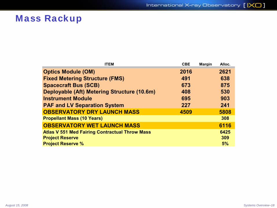
Mass Rackup
ITEM CBE Margin Alloc.
Optics Module (OM) 2016 2621Fixed Metering Structure (FMS) 491 638Spacecraft Bus (SCB) 673 875Deployable (Aft) Metering Structure (10.6m) 408 530Instrument Module 695 903PAF and LV Separation System 227 241OBSERVATORY DRY LAUNCH MASS 4509 5808Propellant Mass (10 Years) 308OBSERVATORY WET LAUNCH MASS 6116Atlas V 551 Med Fairing Contractual Throw Mass 6425Project Reserve 309Project Reserve % 5%

August 15, 2008 Systems Overview–19
Propellant CalculationsACS Tax Contingency Subtotal
Launch Window 5% 0% 11 m/secELV Dispersion Correction 5% 0% 42 m/secMid-Course Correction 5% 5% 11 m/secOrbit Lowering Maneuver 5% 0% 26 m/secL2 Stationkeeping for 5 years 5% 5% 22 m/secMomentum Management for 5 years 0% 5% 2 m/secDe-orbit 5% 5% 1 m/sec
115 m/sec
ALLOCATION PROPELLANT BUDGETAllocation
Allocation Dry Mass 5574.9 kgProp Mass (use equivalent Isp =275) 241.9 kg5% Ullage and Residual 12 kgAllocated Propellant Mass 254.0 kg
DELTA V BUDGET FOR 5 YEARSEstimate10 m/sec40 m/sec10 m/sec25 m/sec20 m/sec1.8 m/sec1 m/sec
Total Equivalent Delta V
ACS Tax Contingency SubtotalLaunch Window 5% 0% 11 m/secELV Dispersion Correction 5% 0% 42 m/secMid-Course Correction 5% 5% 11 m/secOrbit Lowering Maneuver 5% 0% 26 m/secL2 Stationkeeping for 10 years 5% 5% 44 m/secMomentum Management for 10 years 0% 5% 4 m/secDe-orbit 5% 5% 1 m/sec
139 m/sec
ALLOCATION PROPELLANT BUDGETAllocation
Allocation Dry Mass 5574.9 kgProp Mass (use equivalent Isp =275) 293.7 kg5% Ullage and Residual 15 kgAllocated Propellant Mass 308.4 kg
DELTA V BUDGET FOR 10 YEARSEstimate10 m/sec40 m/sec10 m/sec25 m/sec40 m/sec3.6 m/sec1 m/sec
Total Equivalent Delta V

August 15, 2008 Systems Overview–20
Power Loads
(CBE + 30%) Launch Cruise Science Downlink Slew Safehold Peak
Observatory 66 3496 3345 3367 3623 2495 4115Science Payload 0 2874 2874 2874 2797 1897 2874S/C 66 622 471 493 826 598 1241ACS 16 65 70 70 433 57 569C&DH 0 192.4 0 0 0 0 0RF Comm 0 57 57 104 57 57 117Mech 0 0 0 0 0 0 0Propulsion 6.5 6.5 6.5 6.5 6.5 6.5 6.5Power 5 185 217 219 210 175 305Harness 0 25 29 30 28 24 41Thermal 39 91 91 65 91 279 203
Ave Peak Ave Peak Ave Peak StandbyScience Payload 2152 2211 2017 1955 1459FMA 1394 1394 1394 1394 1394 1394 1394 1394XMS 649 701 323 215 65 649 701 323WFI 47 47 211 250 0 211 250 47HXI 5 5 32 32 0 32 32 5XGS 57 64 57 64 0 57 64 0
CBE NumbersMode 1 Mode 2 Unit PowerSafehold
PSE BOL power delivered is the max. EOL load + 20% = 5000W (sized for 10 years L2 mission)
August 15, 2008 Systems Overview–21
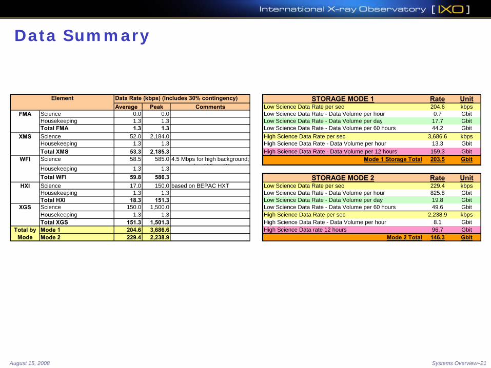
Data Summary
Data Rate (kbps) (Includes 30% contingency) STORAGE MODE 1 Rate UnitAverage Peak Comments Low Science Data Rate per sec 204.6 kbps
Science 0.0 0.0 Low Science Data Rate - Data Volume per hour 0.7 GbitHousekeeping 1.3 1.3 Low Science Data Rate - Data Volume per day 17.7 GbitTotal FMA 1.3 1.3 Low Science Data Rate - Data Volume per 60 hours 44.2 GbitScience 52.0 2,184.0 High Science Data Rate per sec 3,686.6 kbpsHousekeeping 1.3 1.3 High Science Data Rate - Data Volume per hour 13.3 GbitTotal XMS 53.3 2,185.3 High Science Data Rate - Data Volume per 12 hours 159.3 GbitScience 58.5 585.0 4.5 Mbps for high background;
t t d t 1Mb W tMode 1 Storage Total 203.5 Gbit
Housekeeping 1.3 1.3Total WFI 59.8 586.3 STORAGE MODE 2 Rate UnitScience 17.0 150.0 based on BEPAC HXT Low Science Data Rate per sec 229.4 kbpsHousekeeping 1.3 1.3 Low Science Data Rate - Data Volume per hour 825.8 GbitTotal HXI 18.3 151.3 Low Science Data Rate - Data Volume per day 19.8 GbitScience 150.0 1,500.0 Low Science Data Rate - Data Volume per 60 hours 49.6 GbitHousekeeping 1.3 1.3 High Science Data Rate per sec 2,238.9 kbpsTotal XGS 151.3 1,501.3 High Science Data Rate - Data Volume per hour 8.1 GbitMode 1 204.6 3,686.6 High Science Data rate 12 hours 96.7 GbitMode 2 229.4 2,238.9 Mode 2 Total 146.3 Gbit
Element
XGS
Total by Mode
FMA
XMS
WFI
HXI

August 15, 2008 Systems Overview–22
Summary and Future Work
Baseline mission concept appears viable – Spacecraft (i.e. Observatory minus Science Payload) appears feasible with
technologies that exist todayWork is continuing by refining the design in every discipline with recursive iteration thru all system implications until full convergence:
– Finite Element Modeling (launch and on-orbit configurations) to validate mass estimates
– Control System requirements definition (full science requirements flow-
down) and performance analysis
– Alignment Monitor definition and accommodation– Component layout, both Spacecraft and Science Payload
Future mission configuration work is anticipated to address– 20 vs. 25 m focal length trades– Payload modifications to achieve hard X-ray response– Compatibility with micropore mirror– Compatibility with Ariane V launch vehicle