octatrack mkii - elektron.se · important safety and maintenance instructions please read these...
TRANSCRIPT
Octatrack MKIIMore than a sampler
User Manual
FCC compliance statementThis device complies with part 15 of the FCC rules. Operation is subject to the following two conditions: (1) This device may not cause harmful interference, and (2) this device must accept any interference received, including interference that may cause undesired operation.
NOTE: This equipment has been tested and found to comply with the limits for a Class B digital device, pursuant to Part 15 of the FCC Rules. These limits are designed to provide reasonable protection against harmful interference in a residential installation. This equipment generates, uses and can radiate radio frequency energy and, if not installed and used in accordance with the instructions, may cause harmful interference to radio communications. However, there is no guarantee that interference will not occur in a particular installation. If this equipment does cause harmful interference to radio or television reception, which can be determined by turning the equipment off and on, the user is encour-aged to try to correct the interference by one or more of the following measures:
• Reorient or relocate the receiving antenna.• Increase the separation between the equipment and receiver.• Connect the equipment into an outlet on a circuit different from that to which the receiver is
connected.• Consult the dealer or an experienced radio/TV technician for help.
European Union regulation compliance statementThis product has been tested to comply with the Low Voltage Directive 2006/95/EC and the Electromagnetic Compatibility Directive 2004/108/EC. The product meets the requirements of RoHS 2 Directive 2011/65/EU.
This symbol indicates that your product must be disposed of properly according to local laws and regulations.
Legal disclaimerThe information in this document is subject to change without notice and should not be construed as a commitment by Elektron. Elektron assumes no responsibility for any errors that may appear in this doc-ument. Elektron may also make improvements and/or changes in the products and programs described in this document at any time without notice. In no event shall Elektron be liable for any special, indirect, or consequential damages or any damages whatsoever resulting from loss of use, data, or profits, whether in an action of contract, negligence, or other action, arising out of or in connection with the use or performance of this information.
The device contains a non-rechargeable lithium perchlorate battery cell that may need to be recycled separately depending on local environmental laws. If the battery needs replacing, please contact Elek-tron or a local professional technician for servicing.
CanadaThis Class B digital apparatus complies with Canadian ICES-003. Cet appareil numerique de la classe B est conforme a la norme NMB-003.

IMPORTANT SAFETY AND MAINTENANCE INSTRUCTIONSPlease read these instructions carefully and adhere to the operating advice.
1. Do not use this unit near water.2. Never use aggressive cleaners on the casing or on the screen. Remove dust, dirt and fingerprints with
a soft, dry and non-abrasive cloth. More persistent dirt can be removed with a slightly damp cloth using only water. Disconnect all cables while doing this. Only reconnect them when the product is safely dry.
3. To avoid scratches or damage, never use sharp objects near the casing or the screen. Avoid applying any pressure to the screen itself.
4. Install in accordance with the manufacturer’s instructions. Make sure you place the unit on a stable sur-face before use. If you mount the unit in a rack, be sure to tighten all four screws in the rack mount holes.
5. Connect the unit to an easily accessible electrical outlet close to the unit.6. When transporting the unit, use accessories recommended by the manufacturer or the original box and
padding.7. Do not install near any heat sources such as radiators, heat registers, stoves, or any other equipment
(including amplifiers) producing heat. 8. Do not put the PL-2 Protective Cover (Elektron accessory) on the unit while the unit is powered on.9. Make sure there is sufficient air circulation in the room where the unit is kept.10. This product, by itself or in combination with amplifiers, headphones or speakers, is capable of produc-
ing sound levels that may cause permanent hearing loss. Do not operate at a high volume level or at a level that is uncomfortable.
11. Protect the power cord from being walked on or pinched particularly at plugs, convenience receptacles, and the point where they exit from the unit.
12. Use attachments/accessories specified by the manufacturer.13. Unplug this unit during lightning storms or when it is not used for long periods of time.14. Refer all servicing to qualified service technicians. Servicing is required when the unit has been
damaged in any way, liquid has been spilled or objects have fallen into the unit, the unit has been exposed to rain or moisture, does not operate normally, or has been dropped.
WARNINGTo reduce the risk of fire, electrical shock or product damage:
• Do not expose the unit to rain, moisture, dripping or splashing and also avoid placing objects filled with liquid on the unit.
• Do not expose the unit to direct sunlight, nor use it in ambient temperatures exceeding 40°C as this can lead to malfunction.
• Do not open the casing. There are no user repairable or adjustable parts inside. Leave service and re-pairs to trained service technicians only.
• Do not exceed the limitations specified in the Electrical specifications.
SAFETY INSTRUCTIONS FOR THE POWER ADAPTER ELEKTRON PSU-3b• The adapter is not safety grounded and may only be used indoors.• To ensure good ventilation for the adapter, do not place it in tight spaces. To prevent risk of electric
shock and fire because of overheating, ensure that curtains and other objects do not prevent adapter ventilation.
• Do not expose the power adapter to direct sunlight, nor use it in ambient temperatures exceeding 40°C.• Connect the adapter to an easily accessible electrical outlet close to the unit.• The adapter is in standby mode when the power cord is connected. The primary circuit is always active
when the cord is connected to the power outlet. Pull out the cord to completely disconnect the adapter.• In the EU, only use CE approved power cords.

TABLE OF CONTENTS
4
TABLE OF CONTENTS
1. INTRODUCTION . . . . . . . . . . . . . . . . . . . . . . . . . . . . . . . . . . . . . . . . . . . . . . . . . . . . . . . . . . . . . . .101.1 CONVENTIONS IN THIS MANUAL . . . . . . . . . . . . . . . . . . . . . . . . . . . . . . . . . . . . . . . . . . . . . . . . . . . . . . . . . . . . 10
2. THE BACKGROUND OF THE OCTATRACK MKII . . . . . . . . . . . . . . . . . . . . . . . . . . . . . . . . . 112.1 SUGGESTED APPLICATIONS OF THE OCTATRACK MKII . . . . . . . . . . . . . . . . . . . . . . . . . . . . . . . . . . . . . . 11
2.1.1 LOOPER DEVICE . . . . . . . . . . . . . . . . . . . . . . . . . . . . . . . . . . . . . . . . . . . . . . . . . . . . . . . . . . . . . . . . . . . . . . . . . . .112.1.2 RADICAL SOUND PROCESSOR . . . . . . . . . . . . . . . . . . . . . . . . . . . . . . . . . . . . . . . . . . . . . . . . . . . . . . . . . . . .112.1.3 BACKING TRACK MACHINE . . . . . . . . . . . . . . . . . . . . . . . . . . . . . . . . . . . . . . . . . . . . . . . . . . . . . . . . . . . . . . . .112.1.4 LIVE SETUP HUB . . . . . . . . . . . . . . . . . . . . . . . . . . . . . . . . . . . . . . . . . . . . . . . . . . . . . . . . . . . . . . . . . . . . . . . . . . .112.1.5 REMIX TOOL . . . . . . . . . . . . . . . . . . . . . . . . . . . . . . . . . . . . . . . . . . . . . . . . . . . . . . . . . . . . . . . . . . . . . . . . . . . . . . .112.1.6 EFFECTS UNIT EXTRAORDINAIRE . . . . . . . . . . . . . . . . . . . . . . . . . . . . . . . . . . . . . . . . . . . . . . . . . . . . . . . . . .11
3. PANEL LAYOUT AND CONNECTORS . . . . . . . . . . . . . . . . . . . . . . . . . . . . . . . . . . . . . . . . . . . 123.1 FRONT PANEL . . . . . . . . . . . . . . . . . . . . . . . . . . . . . . . . . . . . . . . . . . . . . . . . . . . . . . . . . . . . . . . . . . . . . . . . . . . . . 12
3.2 REAR CONNECTORS. . . . . . . . . . . . . . . . . . . . . . . . . . . . . . . . . . . . . . . . . . . . . . . . . . . . . . . . . . . . . . . . . . . . . . . 14
3.3 OCTATRACK MKII ACCESSORIES . . . . . . . . . . . . . . . . . . . . . . . . . . . . . . . . . . . . . . . . . . . . . . . . . . . . . . . . . . 143.3.1 RACK MOUNT KIT . . . . . . . . . . . . . . . . . . . . . . . . . . . . . . . . . . . . . . . . . . . . . . . . . . . . . . . . . . . . . . . . . . . . . . . . . 143.3.2 CARRYING BAG AND PROTECTIVE LID . . . . . . . . . . . . . . . . . . . . . . . . . . . . . . . . . . . . . . . . . . . . . . . . . . . 14
3.4 THE COMPACT FLASH CARD READER . . . . . . . . . . . . . . . . . . . . . . . . . . . . . . . . . . . . . . . . . . . . . . . . . . . . . 143.4.1 COMPACT FLASH CARD SPECIFICATIONS . . . . . . . . . . . . . . . . . . . . . . . . . . . . . . . . . . . . . . . . . . . . . . . . 15
3.5 CONNECTING THE UNIT . . . . . . . . . . . . . . . . . . . . . . . . . . . . . . . . . . . . . . . . . . . . . . . . . . . . . . . . . . . . . . . . . . . 15
3.6 CARE INSTRUCTIONS . . . . . . . . . . . . . . . . . . . . . . . . . . . . . . . . . . . . . . . . . . . . . . . . . . . . . . . . . . . . . . . . . . . . . 15
4. OVERVIEW OF THE OCTATRACK MKII STRUCTURE . . . . . . . . . . . . . . . . . . . . . . . . . . . .164.1 SETS . . . . . . . . . . . . . . . . . . . . . . . . . . . . . . . . . . . . . . . . . . . . . . . . . . . . . . . . . . . . . . . . . . . . . . . . . . . . . . . . . . . . . . 16
4.2 AUDIO POOL . . . . . . . . . . . . . . . . . . . . . . . . . . . . . . . . . . . . . . . . . . . . . . . . . . . . . . . . . . . . . . . . . . . . . . . . . . . . . . 16
4.3 PROJECTS . . . . . . . . . . . . . . . . . . . . . . . . . . . . . . . . . . . . . . . . . . . . . . . . . . . . . . . . . . . . . . . . . . . . . . . . . . . . . . . . 16
4.4 FLEX AND STATIC SAMPLE SLOT LISTS . . . . . . . . . . . . . . . . . . . . . . . . . . . . . . . . . . . . . . . . . . . . . . . . . . . . 17
4.5 BANKS . . . . . . . . . . . . . . . . . . . . . . . . . . . . . . . . . . . . . . . . . . . . . . . . . . . . . . . . . . . . . . . . . . . . . . . . . . . . . . . . . . . . 17
4.6 PATTERNS . . . . . . . . . . . . . . . . . . . . . . . . . . . . . . . . . . . . . . . . . . . . . . . . . . . . . . . . . . . . . . . . . . . . . . . . . . . . . . . . 17
4.7 PARTS . . . . . . . . . . . . . . . . . . . . . . . . . . . . . . . . . . . . . . . . . . . . . . . . . . . . . . . . . . . . . . . . . . . . . . . . . . . . . . . . . . . . . 17
4.8 SCENES . . . . . . . . . . . . . . . . . . . . . . . . . . . . . . . . . . . . . . . . . . . . . . . . . . . . . . . . . . . . . . . . . . . . . . . . . . . . . . . . . . . 17
4.9 ARRANGEMENTS . . . . . . . . . . . . . . . . . . . . . . . . . . . . . . . . . . . . . . . . . . . . . . . . . . . . . . . . . . . . . . . . . . . . . . . . . . 17
4.10 TRACKS . . . . . . . . . . . . . . . . . . . . . . . . . . . . . . . . . . . . . . . . . . . . . . . . . . . . . . . . . . . . . . . . . . . . . . . . . . . . . . . . . . 17
4.11 MACHINES . . . . . . . . . . . . . . . . . . . . . . . . . . . . . . . . . . . . . . . . . . . . . . . . . . . . . . . . . . . . . . . . . . . . . . . . . . . . . . . . 17
4.12 HOW INFORMATION IS HANDLED . . . . . . . . . . . . . . . . . . . . . . . . . . . . . . . . . . . . . . . . . . . . . . . . . . . . . . . . . 18
5. THE USER INTERFACE . . . . . . . . . . . . . . . . . . . . . . . . . . . . . . . . . . . . . . . . . . . . . . . . . . . . . . . .195.1 MENUS AND WINDOWS . . . . . . . . . . . . . . . . . . . . . . . . . . . . . . . . . . . . . . . . . . . . . . . . . . . . . . . . . . . . . . . . . . . . 19
5.2 PARAMETER EDITING . . . . . . . . . . . . . . . . . . . . . . . . . . . . . . . . . . . . . . . . . . . . . . . . . . . . . . . . . . . . . . . . . . . . . 205.2.1 QUICK PARAMETER EDITING . . . . . . . . . . . . . . . . . . . . . . . . . . . . . . . . . . . . . . . . . . . . . . . . . . . . . . . . . . . . .205.2.2 PARAMETER VALUE JUMP . . . . . . . . . . . . . . . . . . . . . . . . . . . . . . . . . . . . . . . . . . . . . . . . . . . . . . . . . . . . . . . .20
5.3 QUICK SCROLLING . . . . . . . . . . . . . . . . . . . . . . . . . . . . . . . . . . . . . . . . . . . . . . . . . . . . . . . . . . . . . . . . . . . . . . . . 20
5.4 COPY, CLEAR AND PASTE . . . . . . . . . . . . . . . . . . . . . . . . . . . . . . . . . . . . . . . . . . . . . . . . . . . . . . . . . . . . . . . . . 20
5.5 THE NAMING MENU . . . . . . . . . . . . . . . . . . . . . . . . . . . . . . . . . . . . . . . . . . . . . . . . . . . . . . . . . . . . . . . . . . . . . . . . 205.5.1 POP-UP MENU NAMING . . . . . . . . . . . . . . . . . . . . . . . . . . . . . . . . . . . . . . . . . . . . . . . . . . . . . . . . . . . . . . . . . . .20
6. QUICK START . . . . . . . . . . . . . . . . . . . . . . . . . . . . . . . . . . . . . . . . . . . . . . . . . . . . . . . . . . . . . . . . 226.1 DEMO MODE . . . . . . . . . . . . . . . . . . . . . . . . . . . . . . . . . . . . . . . . . . . . . . . . . . . . . . . . . . . . . . . . . . . . . . . . . . . . . . . 22
6.1.1 PLAYING THE DEMO PATTERNS . . . . . . . . . . . . . . . . . . . . . . . . . . . . . . . . . . . . . . . . . . . . . . . . . . . . . . . . . . . 226.1.2 ADJUSTING PARAMETERS . . . . . . . . . . . . . . . . . . . . . . . . . . . . . . . . . . . . . . . . . . . . . . . . . . . . . . . . . . . . . . . . 226.1.3 EXPERIMENTING WITH SCENES . . . . . . . . . . . . . . . . . . . . . . . . . . . . . . . . . . . . . . . . . . . . . . . . . . . . . . . . . . 22
TABLE OF CONTENTS
5
6.1.4 RECORDING A PATTERN USING GRID RECORDING . . . . . . . . . . . . . . . . . . . . . . . . . . . . . . . . . . . . . . . . 226.1.5 RECORDING A PATTERN USING LIVE RECORDING . . . . . . . . . . . . . . . . . . . . . . . . . . . . . . . . . . . . . . . . 226.1.6 USING PARAMETER LOCKS . . . . . . . . . . . . . . . . . . . . . . . . . . . . . . . . . . . . . . . . . . . . . . . . . . . . . . . . . . . . . . . 23
6.2 MOUNTING A SET AND LOADING A PROJECT . . . . . . . . . . . . . . . . . . . . . . . . . . . . . . . . . . . . . . . . . . . . . . 236.2.1 MOUNTING A SET . . . . . . . . . . . . . . . . . . . . . . . . . . . . . . . . . . . . . . . . . . . . . . . . . . . . . . . . . . . . . . . . . . . . . . . . 236.2.2 LOADING A PROJECT . . . . . . . . . . . . . . . . . . . . . . . . . . . . . . . . . . . . . . . . . . . . . . . . . . . . . . . . . . . . . . . . . . . . 24
6.3 LOADING SAMPLES . . . . . . . . . . . . . . . . . . . . . . . . . . . . . . . . . . . . . . . . . . . . . . . . . . . . . . . . . . . . . . . . . . . . . . . 246.3.1 ASSIGNING A MACHINE TO A TRACK . . . . . . . . . . . . . . . . . . . . . . . . . . . . . . . . . . . . . . . . . . . . . . . . . . . . . 246.3.2 ASSIGNING A SAMPLE TO A MACHINE . . . . . . . . . . . . . . . . . . . . . . . . . . . . . . . . . . . . . . . . . . . . . . . . . . . 25
7. SETS . . . . . . . . . . . . . . . . . . . . . . . . . . . . . . . . . . . . . . . . . . . . . . . . . . . . . . . . . . . . . . . . . . . . . . . . . 267.1 CREATING AND MOUNTING A SET . . . . . . . . . . . . . . . . . . . . . . . . . . . . . . . . . . . . . . . . . . . . . . . . . . . . . . . . . . 26
7.2 AUDIO POOL . . . . . . . . . . . . . . . . . . . . . . . . . . . . . . . . . . . . . . . . . . . . . . . . . . . . . . . . . . . . . . . . . . . . . . . . . . . . . . . 277.2.1 ADDING CONTENT TO THE AUDIO POOL . . . . . . . . . . . . . . . . . . . . . . . . . . . . . . . . . . . . . . . . . . . . . . . . . . 277.2.2 AUDIO FILE COMPATIBILITY . . . . . . . . . . . . . . . . . . . . . . . . . . . . . . . . . . . . . . . . . . . . . . . . . . . . . . . . . . . . . . 27
8. PROJECTS . . . . . . . . . . . . . . . . . . . . . . . . . . . . . . . . . . . . . . . . . . . . . . . . . . . . . . . . . . . . . . . . . . . 288.1 PROJECTS AND RAM MEMORY . . . . . . . . . . . . . . . . . . . . . . . . . . . . . . . . . . . . . . . . . . . . . . . . . . . . . . . . . . . . . 28
8.2 LOADING AND CREATING A PROJECT . . . . . . . . . . . . . . . . . . . . . . . . . . . . . . . . . . . . . . . . . . . . . . . . . . . . . . 28
8.3 LOADING SAMPLES TO THE SAMPLE SLOTS . . . . . . . . . . . . . . . . . . . . . . . . . . . . . . . . . . . . . . . . . . . . . . . 298.3.1 LOADING FROM THE QUICK ASSIGN MENU . . . . . . . . . . . . . . . . . . . . . . . . . . . . . . . . . . . . . . . . . . . . . . . 298.3.2 LOADING FROM THE SRC SETUP MENU . . . . . . . . . . . . . . . . . . . . . . . . . . . . . . . . . . . . . . . . . . . . . . . . . .308.3.3 FILE BROWSER . . . . . . . . . . . . . . . . . . . . . . . . . . . . . . . . . . . . . . . . . . . . . . . . . . . . . . . . . . . . . . . . . . . . . . . . . .30
8.4 THE PROJECT MENU . . . . . . . . . . . . . . . . . . . . . . . . . . . . . . . . . . . . . . . . . . . . . . . . . . . . . . . . . . . . . . . . . . . . . . 318.4.1 PROJECT . . . . . . . . . . . . . . . . . . . . . . . . . . . . . . . . . . . . . . . . . . . . . . . . . . . . . . . . . . . . . . . . . . . . . . . . . . . . . . . . . 31
8.5 SYSTEM . . . . . . . . . . . . . . . . . . . . . . . . . . . . . . . . . . . . . . . . . . . . . . . . . . . . . . . . . . . . . . . . . . . . . . . . . . . . . . . . . . . 328.5.1 USB DISK MODE . . . . . . . . . . . . . . . . . . . . . . . . . . . . . . . . . . . . . . . . . . . . . . . . . . . . . . . . . . . . . . . . . . . . . . . . . 328.5.2 OS UPGRADE . . . . . . . . . . . . . . . . . . . . . . . . . . . . . . . . . . . . . . . . . . . . . . . . . . . . . . . . . . . . . . . . . . . . . . . . . . . .338.5.3 DATE/TIME . . . . . . . . . . . . . . . . . . . . . . . . . . . . . . . . . . . . . . . . . . . . . . . . . . . . . . . . . . . . . . . . . . . . . . . . . . . . . .338.5.4 PERSONALIZE . . . . . . . . . . . . . . . . . . . . . . . . . . . . . . . . . . . . . . . . . . . . . . . . . . . . . . . . . . . . . . . . . . . . . . . . . . .338.5.5 CARD TOOLS . . . . . . . . . . . . . . . . . . . . . . . . . . . . . . . . . . . . . . . . . . . . . . . . . . . . . . . . . . . . . . . . . . . . . . . . . . . .348.5.6 STATUS . . . . . . . . . . . . . . . . . . . . . . . . . . . . . . . . . . . . . . . . . . . . . . . . . . . . . . . . . . . . . . . . . . . . . . . . . . . . . . . . . . 35
8.6 CONTROL . . . . . . . . . . . . . . . . . . . . . . . . . . . . . . . . . . . . . . . . . . . . . . . . . . . . . . . . . . . . . . . . . . . . . . . . . . . . . . . . . 358.6.1 AUDIO . . . . . . . . . . . . . . . . . . . . . . . . . . . . . . . . . . . . . . . . . . . . . . . . . . . . . . . . . . . . . . . . . . . . . . . . . . . . . . . . . . . . 358.6.2 INPUT . . . . . . . . . . . . . . . . . . . . . . . . . . . . . . . . . . . . . . . . . . . . . . . . . . . . . . . . . . . . . . . . . . . . . . . . . . . . . . . . . . . .368.6.3 SEQUENCER . . . . . . . . . . . . . . . . . . . . . . . . . . . . . . . . . . . . . . . . . . . . . . . . . . . . . . . . . . . . . . . . . . . . . . . . . . . . .368.6.4 MIDI SEQUENCER . . . . . . . . . . . . . . . . . . . . . . . . . . . . . . . . . . . . . . . . . . . . . . . . . . . . . . . . . . . . . . . . . . . . . . . 378.6.5 MEMORY . . . . . . . . . . . . . . . . . . . . . . . . . . . . . . . . . . . . . . . . . . . . . . . . . . . . . . . . . . . . . . . . . . . . . . . . . . . . . . . . .388.6.6 METRONOME . . . . . . . . . . . . . . . . . . . . . . . . . . . . . . . . . . . . . . . . . . . . . . . . . . . . . . . . . . . . . . . . . . . . . . . . . . . .39
8.7 MIDI . . . . . . . . . . . . . . . . . . . . . . . . . . . . . . . . . . . . . . . . . . . . . . . . . . . . . . . . . . . . . . . . . . . . . . . . . . . . . . . . . . . . . . . 398.7.1 CONTROL . . . . . . . . . . . . . . . . . . . . . . . . . . . . . . . . . . . . . . . . . . . . . . . . . . . . . . . . . . . . . . . . . . . . . . . . . . . . . . . .398.7.2 SYNC. . . . . . . . . . . . . . . . . . . . . . . . . . . . . . . . . . . . . . . . . . . . . . . . . . . . . . . . . . . . . . . . . . . . . . . . . . . . . . . . . . . . .408.7.3 CHANNELS . . . . . . . . . . . . . . . . . . . . . . . . . . . . . . . . . . . . . . . . . . . . . . . . . . . . . . . . . . . . . . . . . . . . . . . . . . . . . . . 418.7.4 TURBO STATUS . . . . . . . . . . . . . . . . . . . . . . . . . . . . . . . . . . . . . . . . . . . . . . . . . . . . . . . . . . . . . . . . . . . . . . . . . . 41
8.8 MIXER MENU . . . . . . . . . . . . . . . . . . . . . . . . . . . . . . . . . . . . . . . . . . . . . . . . . . . . . . . . . . . . . . . . . . . . . . . . . . . . . . 42
8.9 TEMPO MENU . . . . . . . . . . . . . . . . . . . . . . . . . . . . . . . . . . . . . . . . . . . . . . . . . . . . . . . . . . . . . . . . . . . . . . . . . . . . . 438.9.1 TAP TEMPO . . . . . . . . . . . . . . . . . . . . . . . . . . . . . . . . . . . . . . . . . . . . . . . . . . . . . . . . . . . . . . . . . . . . . . . . . . . . . . .438.9.2 PATTERN TEMPO NUDGE . . . . . . . . . . . . . . . . . . . . . . . . . . . . . . . . . . . . . . . . . . . . . . . . . . . . . . . . . . . . . . . .438.9.3 SAMPLE TEMPO NUDGE . . . . . . . . . . . . . . . . . . . . . . . . . . . . . . . . . . . . . . . . . . . . . . . . . . . . . . . . . . . . . . . . .43
9. TRACK RECORDERS AND PICKUP MACHINES . . . . . . . . . . . . . . . . . . . . . . . . . . . . . . . . 449.1 RECORDING EDIT AND SETUP MENUS . . . . . . . . . . . . . . . . . . . . . . . . . . . . . . . . . . . . . . . . . . . . . . . . . . . . . . 44
9.1.1 RECORDING EDIT MENU. . . . . . . . . . . . . . . . . . . . . . . . . . . . . . . . . . . . . . . . . . . . . . . . . . . . . . . . . . . . . . . . . . . 459.1.2 RECORDING SETUP 1 MENU . . . . . . . . . . . . . . . . . . . . . . . . . . . . . . . . . . . . . . . . . . . . . . . . . . . . . . . . . . . . . . 45
TABLE OF CONTENTS
6
9.1.3 RECORDING SETUP 2 MENU . . . . . . . . . . . . . . . . . . . . . . . . . . . . . . . . . . . . . . . . . . . . . . . . . . . . . . . . . . . . . .46
9.2 TRACK RECORDER SAMPLING METHODS . . . . . . . . . . . . . . . . . . . . . . . . . . . . . . . . . . . . . . . . . . . . . . . . . . 479.2.1 MANUAL SAMPLING . . . . . . . . . . . . . . . . . . . . . . . . . . . . . . . . . . . . . . . . . . . . . . . . . . . . . . . . . . . . . . . . . . . . . . 479.2.2 RECORDER TRIG SAMPLING . . . . . . . . . . . . . . . . . . . . . . . . . . . . . . . . . . . . . . . . . . . . . . . . . . . . . . . . . . . . .489.2.3 PLAYBACK OF CAPTURED RECORDER SAMPLES . . . . . . . . . . . . . . . . . . . . . . . . . . . . . . . . . . . . . . . .48
9.3 PICKUP MACHINE SAMPLING . . . . . . . . . . . . . . . . . . . . . . . . . . . . . . . . . . . . . . . . . . . . . . . . . . . . . . . . . . . . . . 499.3.1 MASTER AND SLAVE PICKUP MACHINES . . . . . . . . . . . . . . . . . . . . . . . . . . . . . . . . . . . . . . . . . . . . . . . . . .499.3.2 CONTROLLING THE PICKUP MACHINES . . . . . . . . . . . . . . . . . . . . . . . . . . . . . . . . . . . . . . . . . . . . . . . . . .509.3.2 SEQUENCER TO PICKUP SYNC . . . . . . . . . . . . . . . . . . . . . . . . . . . . . . . . . . . . . . . . . . . . . . . . . . . . . . . . . . .50
10. BANKS, PARTS AND SCENES . . . . . . . . . . . . . . . . . . . . . . . . . . . . . . . . . . . . . . . . . . . . . . . . 5210.1 BANKS . . . . . . . . . . . . . . . . . . . . . . . . . . . . . . . . . . . . . . . . . . . . . . . . . . . . . . . . . . . . . . . . . . . . . . . . . . . . . . . . . . . . 52
10.2 PARTS . . . . . . . . . . . . . . . . . . . . . . . . . . . . . . . . . . . . . . . . . . . . . . . . . . . . . . . . . . . . . . . . . . . . . . . . . . . . . . . . . . . . 5210.2.1 PART QUICK SELECT . . . . . . . . . . . . . . . . . . . . . . . . . . . . . . . . . . . . . . . . . . . . . . . . . . . . . . . . . . . . . . . . . . . . 5210.2.2 PART EDIT . . . . . . . . . . . . . . . . . . . . . . . . . . . . . . . . . . . . . . . . . . . . . . . . . . . . . . . . . . . . . . . . . . . . . . . . . . . . . . 5310.2.3 PART RELOAD . . . . . . . . . . . . . . . . . . . . . . . . . . . . . . . . . . . . . . . . . . . . . . . . . . . . . . . . . . . . . . . . . . . . . . . . . . . 53
10.3 SCENES . . . . . . . . . . . . . . . . . . . . . . . . . . . . . . . . . . . . . . . . . . . . . . . . . . . . . . . . . . . . . . . . . . . . . . . . . . . . . . . . . . 5310.3.1 ASSIGNING AND ADJUSTING SCENES . . . . . . . . . . . . . . . . . . . . . . . . . . . . . . . . . . . . . . . . . . . . . . . . . . . 5310.3.2 SCENE VOLUME LOCKING . . . . . . . . . . . . . . . . . . . . . . . . . . . . . . . . . . . . . . . . . . . . . . . . . . . . . . . . . . . . . . 5410.3.3 SCENE MUTE . . . . . . . . . . . . . . . . . . . . . . . . . . . . . . . . . . . . . . . . . . . . . . . . . . . . . . . . . . . . . . . . . . . . . . . . . . . 5410.3.4 SCENE COPY . . . . . . . . . . . . . . . . . . . . . . . . . . . . . . . . . . . . . . . . . . . . . . . . . . . . . . . . . . . . . . . . . . . . . . . . . . . 5410.3.5 SCENE CLEAR . . . . . . . . . . . . . . . . . . . . . . . . . . . . . . . . . . . . . . . . . . . . . . . . . . . . . . . . . . . . . . . . . . . . . . . . . . 54
11. TRACKS . . . . . . . . . . . . . . . . . . . . . . . . . . . . . . . . . . . . . . . . . . . . . . . . . . . . . . . . . . . . . . . . . . . . . 5511.1 THE DIFFERENCE BETWEEN FLEX AND STATIC MACHINES . . . . . . . . . . . . . . . . . . . . . . . . . . . . . . . . 55
11.2 ASSIGNING MACHINES TO TRACKS . . . . . . . . . . . . . . . . . . . . . . . . . . . . . . . . . . . . . . . . . . . . . . . . . . . . . . . 5511.2.1 ASSIGNING MACHINES IN THE QUICK ASSIGN MENU . . . . . . . . . . . . . . . . . . . . . . . . . . . . . . . . . . . . . 5511.2.2 ASSIGNING MACHINES IN THE SRC SETUP MENU . . . . . . . . . . . . . . . . . . . . . . . . . . . . . . . . . . . . . . . . 56
11.3 ASSIGNING FLEX AND STATIC SAMPLES TO MACHINES . . . . . . . . . . . . . . . . . . . . . . . . . . . . . . . . . . . 5611.3.1 ASSIGNING SAMPLES IN THE QUICK ASSIGN MENU . . . . . . . . . . . . . . . . . . . . . . . . . . . . . . . . . . . . . . 5611.3.2 ASSIGNING SAMPLES IN THE SRC SETUP MENU . . . . . . . . . . . . . . . . . . . . . . . . . . . . . . . . . . . . . . . . . 56
11.4 TRACK PARAMETER PAGES . . . . . . . . . . . . . . . . . . . . . . . . . . . . . . . . . . . . . . . . . . . . . . . . . . . . . . . . . . . . . . . 5711.4.1 TRACK MAIN LEVEL . . . . . . . . . . . . . . . . . . . . . . . . . . . . . . . . . . . . . . . . . . . . . . . . . . . . . . . . . . . . . . . . . . . . . . 5711.4.2 TRACK CUE LEVEL . . . . . . . . . . . . . . . . . . . . . . . . . . . . . . . . . . . . . . . . . . . . . . . . . . . . . . . . . . . . . . . . . . . . . . 5711.4.3 SRC MAIN . . . . . . . . . . . . . . . . . . . . . . . . . . . . . . . . . . . . . . . . . . . . . . . . . . . . . . . . . . . . . . . . . . . . . . . . . . . . . . . 5711.4.4 SRC SETUP . . . . . . . . . . . . . . . . . . . . . . . . . . . . . . . . . . . . . . . . . . . . . . . . . . . . . . . . . . . . . . . . . . . . . . . . . . . . . . 5711.4.5 AMP MAIN . . . . . . . . . . . . . . . . . . . . . . . . . . . . . . . . . . . . . . . . . . . . . . . . . . . . . . . . . . . . . . . . . . . . . . . . . . . . . . . 5811.4.6 AMP SETUP . . . . . . . . . . . . . . . . . . . . . . . . . . . . . . . . . . . . . . . . . . . . . . . . . . . . . . . . . . . . . . . . . . . . . . . . . . . . . . 5811.4.7 LFO MAIN . . . . . . . . . . . . . . . . . . . . . . . . . . . . . . . . . . . . . . . . . . . . . . . . . . . . . . . . . . . . . . . . . . . . . . . . . . . . . . . . 5911.4.8 LFO SETUP . . . . . . . . . . . . . . . . . . . . . . . . . . . . . . . . . . . . . . . . . . . . . . . . . . . . . . . . . . . . . . . . . . . . . . . . . . . . . .6011.4.9 LFO DESIGNER . . . . . . . . . . . . . . . . . . . . . . . . . . . . . . . . . . . . . . . . . . . . . . . . . . . . . . . . . . . . . . . . . . . . . . . . . . 6111.4.10 FX1 AND FX2 . . . . . . . . . . . . . . . . . . . . . . . . . . . . . . . . . . . . . . . . . . . . . . . . . . . . . . . . . . . . . . . . . . . . . . . . . . . . 61
11.5 DIRECT TRACK MUTING . . . . . . . . . . . . . . . . . . . . . . . . . . . . . . . . . . . . . . . . . . . . . . . . . . . . . . . . . . . . . . . . . . . 62
11.6 MAIN AND CUE OUTPUTS ROUTING . . . . . . . . . . . . . . . . . . . . . . . . . . . . . . . . . . . . . . . . . . . . . . . . . . . . . . . 6211.6.1 MAIN OUTPUT ROUTING . . . . . . . . . . . . . . . . . . . . . . . . . . . . . . . . . . . . . . . . . . . . . . . . . . . . . . . . . . . . . . . . . .6311.6.2 CUE OUTPUT ROUTING . . . . . . . . . . . . . . . . . . . . . . . . . . . . . . . . . . . . . . . . . . . . . . . . . . . . . . . . . . . . . . . . . .6311.6.3 PARAMETERS AFFECTING MAIN AND CUE LEVELS . . . . . . . . . . . . . . . . . . . . . . . . . . . . . . . . . . . . . .63
12. PATTERNS . . . . . . . . . . . . . . . . . . . . . . . . . . . . . . . . . . . . . . . . . . . . . . . . . . . . . . . . . . . . . . . . . . 6412.1 TRIG INDICATIONS . . . . . . . . . . . . . . . . . . . . . . . . . . . . . . . . . . . . . . . . . . . . . . . . . . . . . . . . . . . . . . . . . . . . . . . . 64
12.2 BASIC PATTERN OPERATIONS . . . . . . . . . . . . . . . . . . . . . . . . . . . . . . . . . . . . . . . . . . . . . . . . . . . . . . . . . . . . 6412.2.1 SELECTING A PATTERN . . . . . . . . . . . . . . . . . . . . . . . . . . . . . . . . . . . . . . . . . . . . . . . . . . . . . . . . . . . . . . . . . .6412.2.2 PATTERN CONTROL . . . . . . . . . . . . . . . . . . . . . . . . . . . . . . . . . . . . . . . . . . . . . . . . . . . . . . . . . . . . . . . . . . . . .6412.2.3 PATTERN CHAINING . . . . . . . . . . . . . . . . . . . . . . . . . . . . . . . . . . . . . . . . . . . . . . . . . . . . . . . . . . . . . . . . . . . . .64
TABLE OF CONTENTS
7
12.3 RECORDING MODES . . . . . . . . . . . . . . . . . . . . . . . . . . . . . . . . . . . . . . . . . . . . . . . . . . . . . . . . . . . . . . . . . . . . . . 6512.3.1 GRID RECORDING MODE . . . . . . . . . . . . . . . . . . . . . . . . . . . . . . . . . . . . . . . . . . . . . . . . . . . . . . . . . . . . . . . . 6512.3.2 LIVE RECORDING MODE . . . . . . . . . . . . . . . . . . . . . . . . . . . . . . . . . . . . . . . . . . . . . . . . . . . . . . . . . . . . . . . . 65
12.4 TRIG TYPES . . . . . . . . . . . . . . . . . . . . . . . . . . . . . . . . . . . . . . . . . . . . . . . . . . . . . . . . . . . . . . . . . . . . . . . . . . . . . . 6612.4.1 SAMPLE TRIGS . . . . . . . . . . . . . . . . . . . . . . . . . . . . . . . . . . . . . . . . . . . . . . . . . . . . . . . . . . . . . . . . . . . . . . . . . .6612.4.2 NOTE TRIGS . . . . . . . . . . . . . . . . . . . . . . . . . . . . . . . . . . . . . . . . . . . . . . . . . . . . . . . . . . . . . . . . . . . . . . . . . . . .6612.4.3 LOCK TRIGS. . . . . . . . . . . . . . . . . . . . . . . . . . . . . . . . . . . . . . . . . . . . . . . . . . . . . . . . . . . . . . . . . . . . . . . . . . . . .6612.4.4 TRIGLESS TRIGS . . . . . . . . . . . . . . . . . . . . . . . . . . . . . . . . . . . . . . . . . . . . . . . . . . . . . . . . . . . . . . . . . . . . . . . .6612.4.5 ONE SHOT TRIGS . . . . . . . . . . . . . . . . . . . . . . . . . . . . . . . . . . . . . . . . . . . . . . . . . . . . . . . . . . . . . . . . . . . . . . .6612.4.6 SWING TRIGS . . . . . . . . . . . . . . . . . . . . . . . . . . . . . . . . . . . . . . . . . . . . . . . . . . . . . . . . . . . . . . . . . . . . . . . . . . . 6712.4.7 SLIDE TRIGS . . . . . . . . . . . . . . . . . . . . . . . . . . . . . . . . . . . . . . . . . . . . . . . . . . . . . . . . . . . . . . . . . . . . . . . . . . . . 6712.4.8 RECORDER TRIGS . . . . . . . . . . . . . . . . . . . . . . . . . . . . . . . . . . . . . . . . . . . . . . . . . . . . . . . . . . . . . . . . . . . . . . 67
12.5 PARAMETER LOCKS . . . . . . . . . . . . . . . . . . . . . . . . . . . . . . . . . . . . . . . . . . . . . . . . . . . . . . . . . . . . . . . . . . . . . . 67
12.6 SAMPLE LOCKS . . . . . . . . . . . . . . . . . . . . . . . . . . . . . . . . . . . . . . . . . . . . . . . . . . . . . . . . . . . . . . . . . . . . . . . . . . 67
12.7 TRIG MODES . . . . . . . . . . . . . . . . . . . . . . . . . . . . . . . . . . . . . . . . . . . . . . . . . . . . . . . . . . . . . . . . . . . . . . . . . . . . . . 6812.7.1 TRACK . . . . . . . . . . . . . . . . . . . . . . . . . . . . . . . . . . . . . . . . . . . . . . . . . . . . . . . . . . . . . . . . . . . . . . . . . . . . . . . . . . .6812.7.2 CHROMATIC . . . . . . . . . . . . . . . . . . . . . . . . . . . . . . . . . . . . . . . . . . . . . . . . . . . . . . . . . . . . . . . . . . . . . . . . . . . . .6812.7.3 SLOTS . . . . . . . . . . . . . . . . . . . . . . . . . . . . . . . . . . . . . . . . . . . . . . . . . . . . . . . . . . . . . . . . . . . . . . . . . . . . . . . . . . .6912.7.4 SLICES . . . . . . . . . . . . . . . . . . . . . . . . . . . . . . . . . . . . . . . . . . . . . . . . . . . . . . . . . . . . . . . . . . . . . . . . . . . . . . . . . .6912.7.5 QUICK MUTE . . . . . . . . . . . . . . . . . . . . . . . . . . . . . . . . . . . . . . . . . . . . . . . . . . . . . . . . . . . . . . . . . . . . . . . . . . . .6912.7.6 DELAY CONTROL . . . . . . . . . . . . . . . . . . . . . . . . . . . . . . . . . . . . . . . . . . . . . . . . . . . . . . . . . . . . . . . . . . . . . . . .69
12.8 SEQUENCER COPY, PASTE AND CLEAR OPERATIONS . . . . . . . . . . . . . . . . . . . . . . . . . . . . . . . . . . . . . 7012.8.1 PATTERN COPY . . . . . . . . . . . . . . . . . . . . . . . . . . . . . . . . . . . . . . . . . . . . . . . . . . . . . . . . . . . . . . . . . . . . . . . . . . 7012.8.2 PATTERN CLEAR . . . . . . . . . . . . . . . . . . . . . . . . . . . . . . . . . . . . . . . . . . . . . . . . . . . . . . . . . . . . . . . . . . . . . . . . 7012.8.3 TRACK COPY . . . . . . . . . . . . . . . . . . . . . . . . . . . . . . . . . . . . . . . . . . . . . . . . . . . . . . . . . . . . . . . . . . . . . . . . . . . 7012.8.4 TRACK CLEAR . . . . . . . . . . . . . . . . . . . . . . . . . . . . . . . . . . . . . . . . . . . . . . . . . . . . . . . . . . . . . . . . . . . . . . . . . . 7112.8.5 TRACK PAGE COPY . . . . . . . . . . . . . . . . . . . . . . . . . . . . . . . . . . . . . . . . . . . . . . . . . . . . . . . . . . . . . . . . . . . . . 7112.8.6 TRACK PAGE CLEAR . . . . . . . . . . . . . . . . . . . . . . . . . . . . . . . . . . . . . . . . . . . . . . . . . . . . . . . . . . . . . . . . . . . . 7112.8.7 TRACK PARAMETER PAGE COPY . . . . . . . . . . . . . . . . . . . . . . . . . . . . . . . . . . . . . . . . . . . . . . . . . . . . . . . . 7112.8.8 TRACK PARAMETER PAGE CLEAR . . . . . . . . . . . . . . . . . . . . . . . . . . . . . . . . . . . . . . . . . . . . . . . . . . . . . . . 7112.8.9 TRIG COPY . . . . . . . . . . . . . . . . . . . . . . . . . . . . . . . . . . . . . . . . . . . . . . . . . . . . . . . . . . . . . . . . . . . . . . . . . . . . . . 7112.8.10 TRIG LOCK CLEAR . . . . . . . . . . . . . . . . . . . . . . . . . . . . . . . . . . . . . . . . . . . . . . . . . . . . . . . . . . . . . . . . . . . . . 72
12.9 TRACK TRIG EDIT MENU . . . . . . . . . . . . . . . . . . . . . . . . . . . . . . . . . . . . . . . . . . . . . . . . . . . . . . . . . . . . . . . . . . 7212.9.1 TRIGS . . . . . . . . . . . . . . . . . . . . . . . . . . . . . . . . . . . . . . . . . . . . . . . . . . . . . . . . . . . . . . . . . . . . . . . . . . . . . . . . . . . . 7212.9.2 SLIDE . . . . . . . . . . . . . . . . . . . . . . . . . . . . . . . . . . . . . . . . . . . . . . . . . . . . . . . . . . . . . . . . . . . . . . . . . . . . . . . . . . . 7212.9.3 SWING . . . . . . . . . . . . . . . . . . . . . . . . . . . . . . . . . . . . . . . . . . . . . . . . . . . . . . . . . . . . . . . . . . . . . . . . . . . . . . . . . . 7312.9.4 RECORDER TRIGS. . . . . . . . . . . . . . . . . . . . . . . . . . . . . . . . . . . . . . . . . . . . . . . . . . . . . . . . . . . . . . . . . . . . . . . 73
12.10 PATTERN SETTINGS MENU. . . . . . . . . . . . . . . . . . . . . . . . . . . . . . . . . . . . . . . . . . . . . . . . . . . . . . . . . . . . . . . 7312.10.1 PATTERN . . . . . . . . . . . . . . . . . . . . . . . . . . . . . . . . . . . . . . . . . . . . . . . . . . . . . . . . . . . . . . . . . . . . . . . . . . . . . . . . 74
12.11 MICRO TIMING . . . . . . . . . . . . . . . . . . . . . . . . . . . . . . . . . . . . . . . . . . . . . . . . . . . . . . . . . . . . . . . . . . . . . . . . . . . 75
12.12 CONDITIONAL LOCKS . . . . . . . . . . . . . . . . . . . . . . . . . . . . . . . . . . . . . . . . . . . . . . . . . . . . . . . . . . . . . . . . . . . . 76
12.13 FILL MODE . . . . . . . . . . . . . . . . . . . . . . . . . . . . . . . . . . . . . . . . . . . . . . . . . . . . . . . . . . . . . . . . . . . . . . . . . . . . . . . 77
12.14 SCALE SETUP . . . . . . . . . . . . . . . . . . . . . . . . . . . . . . . . . . . . . . . . . . . . . . . . . . . . . . . . . . . . . . . . . . . . . . . . . . . 7712.14.1 NORMAL . . . . . . . . . . . . . . . . . . . . . . . . . . . . . . . . . . . . . . . . . . . . . . . . . . . . . . . . . . . . . . . . . . . . . . . . . . . . . . . . 7712.14.2 PER TRACK . . . . . . . . . . . . . . . . . . . . . . . . . . . . . . . . . . . . . . . . . . . . . . . . . . . . . . . . . . . . . . . . . . . . . . . . . . . . . 78
13. THE AUDIO EDITOR . . . . . . . . . . . . . . . . . . . . . . . . . . . . . . . . . . . . . . . . . . . . . . . . . . . . . . . . . 7913.1 ACCESSING THE AUDIO EDITOR . . . . . . . . . . . . . . . . . . . . . . . . . . . . . . . . . . . . . . . . . . . . . . . . . . . . . . . . . . . 79
13.1.1 ACCESS FROM THE QUICK ASSIGN MENU . . . . . . . . . . . . . . . . . . . . . . . . . . . . . . . . . . . . . . . . . . . . . . . . 7913.1.2 ACCESS FROM THE SRC SETUP MENU . . . . . . . . . . . . . . . . . . . . . . . . . . . . . . . . . . . . . . . . . . . . . . . . . . 7913.1.3 ACCESS FROM TRACKS AND TRACK RECORDERS . . . . . . . . . . . . . . . . . . . . . . . . . . . . . . . . . . . . . . . 79
13.2 AUDIO EDITOR FUNCTIONALITY . . . . . . . . . . . . . . . . . . . . . . . . . . . . . . . . . . . . . . . . . . . . . . . . . . . . . . . . . . 7913.2.1 TRIM . . . . . . . . . . . . . . . . . . . . . . . . . . . . . . . . . . . . . . . . . . . . . . . . . . . . . . . . . . . . . . . . . . . . . . . . . . . . . . . . . . . . . 79
TABLE OF CONTENTS
8
13.2.2 SLICE . . . . . . . . . . . . . . . . . . . . . . . . . . . . . . . . . . . . . . . . . . . . . . . . . . . . . . . . . . . . . . . . . . . . . . . . . . . . . . . . . . .8013.2.3 EDIT . . . . . . . . . . . . . . . . . . . . . . . . . . . . . . . . . . . . . . . . . . . . . . . . . . . . . . . . . . . . . . . . . . . . . . . . . . . . . . . . . . . .8213.2.4 ATTRIBUTES . . . . . . . . . . . . . . . . . . . . . . . . . . . . . . . . . . . . . . . . . . . . . . . . . . . . . . . . . . . . . . . . . . . . . . . . . . . .8313.2.5 FILE . . . . . . . . . . . . . . . . . . . . . . . . . . . . . . . . . . . . . . . . . . . . . . . . . . . . . . . . . . . . . . . . . . . . . . . . . . . . . . . . . . . . . 85
14. THE ARRANGER . . . . . . . . . . . . . . . . . . . . . . . . . . . . . . . . . . . . . . . . . . . . . . . . . . . . . . . . . . . . . 8614.1 THE ARRANGER MENU . . . . . . . . . . . . . . . . . . . . . . . . . . . . . . . . . . . . . . . . . . . . . . . . . . . . . . . . . . . . . . . . . . . . 86
14.1.1 EDIT . . . . . . . . . . . . . . . . . . . . . . . . . . . . . . . . . . . . . . . . . . . . . . . . . . . . . . . . . . . . . . . . . . . . . . . . . . . . . . . . . . . . . .8614.1.2 RENAME . . . . . . . . . . . . . . . . . . . . . . . . . . . . . . . . . . . . . . . . . . . . . . . . . . . . . . . . . . . . . . . . . . . . . . . . . . . . . . . . .8814.1.3 CHANGE . . . . . . . . . . . . . . . . . . . . . . . . . . . . . . . . . . . . . . . . . . . . . . . . . . . . . . . . . . . . . . . . . . . . . . . . . . . . . . . . .8814.1.4 CHAIN . . . . . . . . . . . . . . . . . . . . . . . . . . . . . . . . . . . . . . . . . . . . . . . . . . . . . . . . . . . . . . . . . . . . . . . . . . . . . . . . . . .8814.1.5 CLEAR . . . . . . . . . . . . . . . . . . . . . . . . . . . . . . . . . . . . . . . . . . . . . . . . . . . . . . . . . . . . . . . . . . . . . . . . . . . . . . . . . . .8814.1.6 SAVE . . . . . . . . . . . . . . . . . . . . . . . . . . . . . . . . . . . . . . . . . . . . . . . . . . . . . . . . . . . . . . . . . . . . . . . . . . . . . . . . . . . .8814.1.7 RELOAD . . . . . . . . . . . . . . . . . . . . . . . . . . . . . . . . . . . . . . . . . . . . . . . . . . . . . . . . . . . . . . . . . . . . . . . . . . . . . . . . .88
15. THE MIDI SEQUENCER . . . . . . . . . . . . . . . . . . . . . . . . . . . . . . . . . . . . . . . . . . . . . . . . . . . . . . 8915.1 ACCESSING THE MIDI SEQUENCER . . . . . . . . . . . . . . . . . . . . . . . . . . . . . . . . . . . . . . . . . . . . . . . . . . . . . . . . 89
15.2 HOW MIDI IS ROUTED . . . . . . . . . . . . . . . . . . . . . . . . . . . . . . . . . . . . . . . . . . . . . . . . . . . . . . . . . . . . . . . . . . . . . 89
15.3 MIDI MODE LIVE RECORDING AND PARAMETER LOCKING . . . . . . . . . . . . . . . . . . . . . . . . . . . . . . . . . 90
15.4 MIDI TRACK PARAMETER PAGES . . . . . . . . . . . . . . . . . . . . . . . . . . . . . . . . . . . . . . . . . . . . . . . . . . . . . . . . . 9015.4.1 NOTE MAIN . . . . . . . . . . . . . . . . . . . . . . . . . . . . . . . . . . . . . . . . . . . . . . . . . . . . . . . . . . . . . . . . . . . . . . . . . . . . . .9015.4.2 NOTE SETUP . . . . . . . . . . . . . . . . . . . . . . . . . . . . . . . . . . . . . . . . . . . . . . . . . . . . . . . . . . . . . . . . . . . . . . . . . . . . 9115.4.3 ARPEGGIATOR MAIN . . . . . . . . . . . . . . . . . . . . . . . . . . . . . . . . . . . . . . . . . . . . . . . . . . . . . . . . . . . . . . . . . . . . 9115.4.4 ARPEGGIATOR SETUP . . . . . . . . . . . . . . . . . . . . . . . . . . . . . . . . . . . . . . . . . . . . . . . . . . . . . . . . . . . . . . . . . . . 9215.4.5 MIDI LFO MAIN . . . . . . . . . . . . . . . . . . . . . . . . . . . . . . . . . . . . . . . . . . . . . . . . . . . . . . . . . . . . . . . . . . . . . . . . . . 9215.4.6 MIDI LFO SETUP . . . . . . . . . . . . . . . . . . . . . . . . . . . . . . . . . . . . . . . . . . . . . . . . . . . . . . . . . . . . . . . . . . . . . . . . . 9215.4.7 CTRL 1 MAIN . . . . . . . . . . . . . . . . . . . . . . . . . . . . . . . . . . . . . . . . . . . . . . . . . . . . . . . . . . . . . . . . . . . . . . . . . . . . .9315.4.8 CTRL 1 SETUP . . . . . . . . . . . . . . . . . . . . . . . . . . . . . . . . . . . . . . . . . . . . . . . . . . . . . . . . . . . . . . . . . . . . . . . . . . .9315.4.9 CTRL 2 MAIN . . . . . . . . . . . . . . . . . . . . . . . . . . . . . . . . . . . . . . . . . . . . . . . . . . . . . . . . . . . . . . . . . . . . . . . . . . . .9315.4.10 CTRL 2 SETUP . . . . . . . . . . . . . . . . . . . . . . . . . . . . . . . . . . . . . . . . . . . . . . . . . . . . . . . . . . . . . . . . . . . . . . . . . .94
16. OCTATRACK MKII SETUP EXAMPLES . . . . . . . . . . . . . . . . . . . . . . . . . . . . . . . . . . . . . . . . 9516.1 OCTATRACK MKII AS A PERFORMANCE HUB . . . . . . . . . . . . . . . . . . . . . . . . . . . . . . . . . . . . . . . . . . . . . . 95
16.1.1 DIR METHOD . . . . . . . . . . . . . . . . . . . . . . . . . . . . . . . . . . . . . . . . . . . . . . . . . . . . . . . . . . . . . . . . . . . . . . . . . . . . . 9516.1.2 THRU MACHINES METHOD . . . . . . . . . . . . . . . . . . . . . . . . . . . . . . . . . . . . . . . . . . . . . . . . . . . . . . . . . . . . . .96
16.2 OCTATRACK MKII WITH EXTERNAL EFFECTS . . . . . . . . . . . . . . . . . . . . . . . . . . . . . . . . . . . . . . . . . . . . . 97
16.3 OCTATRACK MKII PROCESSING LIVE INSTRUMENTS . . . . . . . . . . . . . . . . . . . . . . . . . . . . . . . . . . . . . . 98
16.4 OCTATRACK MKII AS A DJ MIXER AND SAMPLER . . . . . . . . . . . . . . . . . . . . . . . . . . . . . . . . . . . . . . . . . . 9916.4.1 DJ MIXING USING THE DIR METHOD . . . . . . . . . . . . . . . . . . . . . . . . . . . . . . . . . . . . . . . . . . . . . . . . . . . . .9916.4.2 DJ MIXING USING THE THRU METHOD . . . . . . . . . . . . . . . . . . . . . . . . . . . . . . . . . . . . . . . . . . . . . . . . . 100
16.5 OCTATRACK MKII AS A MIDI CONTROL CENTER . . . . . . . . . . . . . . . . . . . . . . . . . . . . . . . . . . . . . . . . . . 10116.5.1 MIDI CONTROL USING CC DIRECT CONNECT AND THE AUTO CHANNEL . . . . . . . . . . . . . . . . 101
17. OCTATRACK MKII TUTORIALS . . . . . . . . . . . . . . . . . . . . . . . . . . . . . . . . . . . . . . . . . . . . . . 10317.1 TRACK RECORDER SAMPLING . . . . . . . . . . . . . . . . . . . . . . . . . . . . . . . . . . . . . . . . . . . . . . . . . . . . . . . . . . . . 103
17.1.1 MANUAL SAMPLING . . . . . . . . . . . . . . . . . . . . . . . . . . . . . . . . . . . . . . . . . . . . . . . . . . . . . . . . . . . . . . . . . . . . . 10317.1.2 SAMPLING USING RECORDER TRIGS . . . . . . . . . . . . . . . . . . . . . . . . . . . . . . . . . . . . . . . . . . . . . . . . . . . . 10317.1.3 PLAYBACK OF CAPTURED RECORDER SAMPLES . . . . . . . . . . . . . . . . . . . . . . . . . . . . . . . . . . . . . . . 10417.1.4 PICKUP MACHINE SAMPLING . . . . . . . . . . . . . . . . . . . . . . . . . . . . . . . . . . . . . . . . . . . . . . . . . . . . . . . . . . . . 10417.1.5 CONTROLLING THE PICK UP MACHINES WITH A MIDI FOOT CONTROLLER . . . . . . . . . . . . . . 105
17.2 LOOP REMIXING . . . . . . . . . . . . . . . . . . . . . . . . . . . . . . . . . . . . . . . . . . . . . . . . . . . . . . . . . . . . . . . . . . . . . . . . . 10617.2.1 LOOP REMIXING USING SLICES . . . . . . . . . . . . . . . . . . . . . . . . . . . . . . . . . . . . . . . . . . . . . . . . . . . . . . . . . 10617.2.2 LOOP REMIXING USING THE CROSSFADER . . . . . . . . . . . . . . . . . . . . . . . . . . . . . . . . . . . . . . . . . . . . . 107
17.3 PREPARING LOOPS AND SAMPLES . . . . . . . . . . . . . . . . . . . . . . . . . . . . . . . . . . . . . . . . . . . . . . . . . . . . . . . 108
17.4 THE OCTATRACK MKII AS A DJ DECK. . . . . . . . . . . . . . . . . . . . . . . . . . . . . . . . . . . . . . . . . . . . . . . . . . . . . 109
TABLE OF CONTENTS
9
17.5 THE OCTATRACK MKII AS AN EFFECTS PROCESSOR . . . . . . . . . . . . . . . . . . . . . . . . . . . . . . . . . . . . . 110
18. STARTUP MENU . . . . . . . . . . . . . . . . . . . . . . . . . . . . . . . . . . . . . . . . . . . . . . . . . . . . . . . . . . . . . 11118.1 TEST MODE . . . . . . . . . . . . . . . . . . . . . . . . . . . . . . . . . . . . . . . . . . . . . . . . . . . . . . . . . . . . . . . . . . . . . . . . . . . . . . . 111
18.2 EMPTY RESET . . . . . . . . . . . . . . . . . . . . . . . . . . . . . . . . . . . . . . . . . . . . . . . . . . . . . . . . . . . . . . . . . . . . . . . . . . . . 111
18.3 MIDI UPGRADE . . . . . . . . . . . . . . . . . . . . . . . . . . . . . . . . . . . . . . . . . . . . . . . . . . . . . . . . . . . . . . . . . . . . . . . . . . . 111
18.4 SEND UPGRADE . . . . . . . . . . . . . . . . . . . . . . . . . . . . . . . . . . . . . . . . . . . . . . . . . . . . . . . . . . . . . . . . . . . . . . . . . . 111
18.5 EXIT . . . . . . . . . . . . . . . . . . . . . . . . . . . . . . . . . . . . . . . . . . . . . . . . . . . . . . . . . . . . . . . . . . . . . . . . . . . . . . . . . . . . . .112
19. SUMMARY OF KEY COMBINATIONS . . . . . . . . . . . . . . . . . . . . . . . . . . . . . . . . . . . . . . . . . 113
20. TECHNICAL INFORMATION . . . . . . . . . . . . . . . . . . . . . . . . . . . . . . . . . . . . . . . . . . . . . . . . . 115
21. CREDITS AND CONTACT INFORMATION . . . . . . . . . . . . . . . . . . . . . . . . . . . . . . . . . . . . . 115
APPENDIX A: MACHINE REFERENCE . . . . . . . . . . . . . . . . . . . . . . . . . . . . . . . . . . . . . . . . . . . . 116A.1 THRU MACHINE . . . . . . . . . . . . . . . . . . . . . . . . . . . . . . . . . . . . . . . . . . . . . . . . . . . . . . . . . . . . . . . . . . . . . . . . . . . 116
A.2 FLEX MACHINE . . . . . . . . . . . . . . . . . . . . . . . . . . . . . . . . . . . . . . . . . . . . . . . . . . . . . . . . . . . . . . . . . . . . . . . . . . . .117
A.3 STATIC MACHINE . . . . . . . . . . . . . . . . . . . . . . . . . . . . . . . . . . . . . . . . . . . . . . . . . . . . . . . . . . . . . . . . . . . . . . . . . 118
A.4 NEIGHBOR MACHINE . . . . . . . . . . . . . . . . . . . . . . . . . . . . . . . . . . . . . . . . . . . . . . . . . . . . . . . . . . . . . . . . . . . . . 119
A.5 PICKUP MACHINE . . . . . . . . . . . . . . . . . . . . . . . . . . . . . . . . . . . . . . . . . . . . . . . . . . . . . . . . . . . . . . . . . . . . . . . . 120
APPENDIX B: EFFECTS REFERENCE . . . . . . . . . . . . . . . . . . . . . . . . . . . . . . . . . . . . . . . . . . . . 121B.1 NONE . . . . . . . . . . . . . . . . . . . . . . . . . . . . . . . . . . . . . . . . . . . . . . . . . . . . . . . . . . . . . . . . . . . . . . . . . . . . . . . . . . . . . .121
B.2 12/24DB MULTI MODE FILTER . . . . . . . . . . . . . . . . . . . . . . . . . . . . . . . . . . . . . . . . . . . . . . . . . . . . . . . . . . . . . 122
B.3 2-BAND PARAMETRIC EQ . . . . . . . . . . . . . . . . . . . . . . . . . . . . . . . . . . . . . . . . . . . . . . . . . . . . . . . . . . . . . . . . . 123
B.4 DJ STYLE KILL EQ . . . . . . . . . . . . . . . . . . . . . . . . . . . . . . . . . . . . . . . . . . . . . . . . . . . . . . . . . . . . . . . . . . . . . . . . 124
B.5 2-10 STAGE PHASER . . . . . . . . . . . . . . . . . . . . . . . . . . . . . . . . . . . . . . . . . . . . . . . . . . . . . . . . . . . . . . . . . . . . . . 125
B.6 FLANGER . . . . . . . . . . . . . . . . . . . . . . . . . . . . . . . . . . . . . . . . . . . . . . . . . . . . . . . . . . . . . . . . . . . . . . . . . . . . . . . . 126
B.7 2-10 TAP CHORUS . . . . . . . . . . . . . . . . . . . . . . . . . . . . . . . . . . . . . . . . . . . . . . . . . . . . . . . . . . . . . . . . . . . . . . . . 127
B.8 SPATIALIZER . . . . . . . . . . . . . . . . . . . . . . . . . . . . . . . . . . . . . . . . . . . . . . . . . . . . . . . . . . . . . . . . . . . . . . . . . . . . . 128
B.9 COMB FILTER . . . . . . . . . . . . . . . . . . . . . . . . . . . . . . . . . . . . . . . . . . . . . . . . . . . . . . . . . . . . . . . . . . . . . . . . . . . . 129
B.10 DYNAMIX COMPRESSOR . . . . . . . . . . . . . . . . . . . . . . . . . . . . . . . . . . . . . . . . . . . . . . . . . . . . . . . . . . . . . . . . 130
B.11 LO-FI COLLECTION . . . . . . . . . . . . . . . . . . . . . . . . . . . . . . . . . . . . . . . . . . . . . . . . . . . . . . . . . . . . . . . . . . . . . . . 131
B.12 ECHO FREEZE DELAY . . . . . . . . . . . . . . . . . . . . . . . . . . . . . . . . . . . . . . . . . . . . . . . . . . . . . . . . . . . . . . . . . . . . 132
B.13 GATEBOX PLATE REVERB. . . . . . . . . . . . . . . . . . . . . . . . . . . . . . . . . . . . . . . . . . . . . . . . . . . . . . . . . . . . . . . . 133
B.14 SPRING REVERB . . . . . . . . . . . . . . . . . . . . . . . . . . . . . . . . . . . . . . . . . . . . . . . . . . . . . . . . . . . . . . . . . . . . . . . . . 134
B.15 DARK REVERB . . . . . . . . . . . . . . . . . . . . . . . . . . . . . . . . . . . . . . . . . . . . . . . . . . . . . . . . . . . . . . . . . . . . . . . . . . . 135
APPENDIX C: MIDI CONTROL REFERENCE . . . . . . . . . . . . . . . . . . . . . . . . . . . . . . . . . . . . . 136C.1 NOTE MAPPING . . . . . . . . . . . . . . . . . . . . . . . . . . . . . . . . . . . . . . . . . . . . . . . . . . . . . . . . . . . . . . . . . . . . . . . . . . . 136
C.2 CTRL CHANGE MAPPINGS . . . . . . . . . . . . . . . . . . . . . . . . . . . . . . . . . . . . . . . . . . . . . . . . . . . . . . . . . . . . . . . . 137
C.3 MIDI MODE CTRL CHANGE MAPPINGS . . . . . . . . . . . . . . . . . . . . . . . . . . . . . . . . . . . . . . . . . . . . . . . . . . . . 138
INDEX . . . . . . . . . . . . . . . . . . . . . . . . . . . . . . . . . . . . . . . . . . . . . . . . . . . . . . . . . . . . . . . . . . . . . . . . . 140
1. INTRODUCTION
10
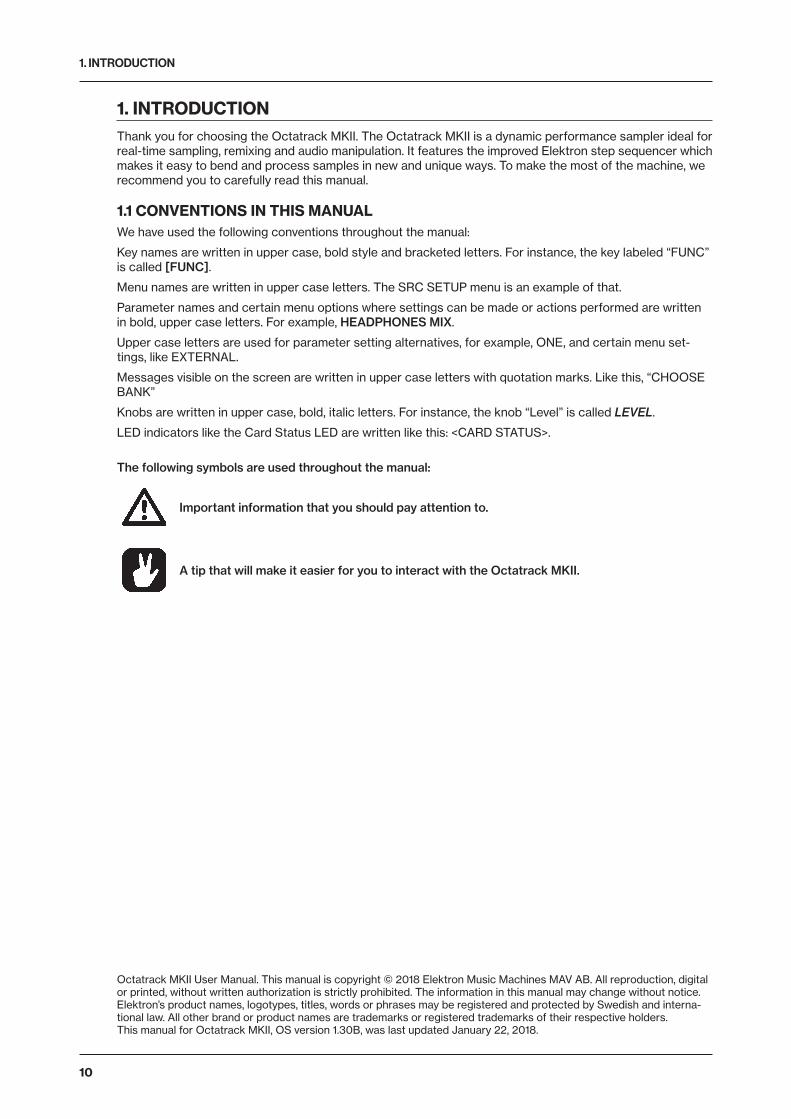
1. INTRODUCTIONThank you for choosing the Octatrack MKII. The Octatrack MKII is a dynamic performance sampler ideal for real-time sampling, remixing and audio manipulation. It features the improved Elektron step sequencer which makes it easy to bend and process samples in new and unique ways. To make the most of the machine, we recommend you to carefully read this manual.
1.1 CONVENTIONS IN THIS MANUALWe have used the following conventions throughout the manual:
Key names are written in upper case, bold style and bracketed letters. For instance, the key labeled “FUNC” is called [FUNC].
Menu names are written in upper case letters. The SRC SETUP menu is an example of that.
Parameter names and certain menu options where settings can be made or actions performed are written in bold, upper case letters. For example, HEADPHONES MIX.
Upper case letters are used for parameter setting alternatives, for example, ONE, and certain menu set-tings, like EXTERNAL.
Messages visible on the screen are written in upper case letters with quotation marks. Like this, “CHOOSE BANK”
Knobs are written in upper case, bold, italic letters. For instance, the knob “Level” is called LEVEL.
LED indicators like the Card Status LED are written like this: <CARD STATUS>.
The following symbols are used throughout the manual:
Important information that you should pay attention to.
A tip that will make it easier for you to interact with the Octatrack MKII.
Octatrack MKII User Manual. This manual is copyright © 2018 Elektron Music Machines MAV AB. All reproduction, digital or printed, without written authorization is strictly prohibited. The information in this manual may change without notice. Elektron’s product names, logotypes, titles, words or phrases may be registered and protected by Swedish and interna-tional law. All other brand or product names are trademarks or registered trademarks of their respective holders. This manual for Octatrack MKII, OS version 1.30B, was last updated January 22, 2018.
2. THE BACKGROUND OF THE OCTATRACK MKII
11
2. THE BACKGROUND OF THE OCTATRACK MKIIWith the Octatrack we wanted to create a sampler that would regard recorded material not as inflexible sounds, but rather as something highly malleable. This is one of the reasons why we made the Octatrack. The other one is because of the stage. The Octatrack on the other hand was designed to be a streamlined, reliable and straightforward machine allowing live performers to really add something extra to their sets. It can act as a backing track machine, a second turntable, a source of experimental soundscapes or simply as an instrument encouraging improvisation and fun.
During its seven year life span, the Octatrack quickly became one of the most widely used live performance samplers. An industry standard if there ever was one. It undoubtedly changed the way gear setups look like and gave artists the power to perform live in the truest sense of the word.
Now we give you Octatrack MKII. Sharper, better, more robust. Enhanced on many levels to ensure world class sample mangling potential.
Durable back-lit buttons, upgraded silky smooth crossfader, ultra crisp OLED screen, precise hi-res encoders, balanced audio inputs, improved user interface. Octatrack MKII is a better version of itself. A classic reborn.
We hope this instrument will keep you company for years to come and that you will find it both indispens-able and liberating.
Have fun twisting those samples,
- The Elektron Team
2.1 SUGGESTED APPLICATIONS OF THE OCTATRACK MKIIThe flexibility of the Octatrack MKII makes it a very powerful device suited to a wide range of tasks. Here a few of them are presented.
2.1.1 LOOPER DEVICEThe Octatrack MKII is ideal for DJ’s and live performers. You will be able to quickly sample a turntable or other sound sources present on the stage and instantly play back and affect the recorded loop. Add pre- recorded loops and sounds to samples captured in real-time to take your performance to a completely new level. The real-time timestretch will make sure everything stays in sync.
2.1.2 RADICAL SOUND PROCESSORThe combined power of the sampling engine, the sequencer and the FX blocks makes the Octatrack MKII a very powerful audio mangler. This functionality is great when working in the studio and wanting to obtain unique sounds and textures.
2.1.3 BACKING TRACK MACHINEEach of the eight stereo tracks can stream gigabyte-large samples. Despite the large size of the samples they can still be subject to timestretch. Change the tempo of the Octatrack MKII and the backing track samples can be timestretched accordingly. On top of this you can treat the samples with the Octatrack MKII effects and sequencer tricks.
2.1.4 LIVE SETUP HUBThe two input pairs combined with the extensive audio routing possibilities allow the Octatrack MKII to function as a mixer. Connect for example a Machinedrum and a Monomachine to the inputs and enjoy a complete live setup with extreme possibilities.
2.1.5 REMIX TOOLIt is easy to change the pitch of different sections of a vocal sample without changing the overall tempo of the sample. Chopping up and rearranging samples and loops is extremely simple thanks to features like the LFO designer and slice points. The Octatrack MKII lets you break down audio content and re-structure it in new and interesting ways.
2.1.6 EFFECTS UNIT EXTRAORDINAIREChained FX blocks paired with automated real time sampling can warble and twist incoming audio in ways previously unachievable by a single machine. Two chains, each with 8 simultaneous effects, can be active at the same time.

3. PANEL LAYOUT AND CONNECTORS
12
3. PANEL LAYOUT AND CONNECTORS
1 2 43 5 6
9
8
10
7
15 1116
21
22
12131718
23
29
1920 14
24 25 26 27 28
30
3.1 FRONT PANELThe Octatrack MKII front panel. For a more comprehensive list of key combinations, please see “19. SUM-MARY OF KEY COMBINATIONS” on page 113.
1. [REC1], [REC2] keys are used for real-time sampling through the external inputs. There is one key per audio input pair. The <REC> LEDs indicate the strength of the signal received on the external inputs. When in the RECORD SETUP menu these LEDs also indicate the source selection for recorder trigs. [FUNC] + [REC1/2] opens the RECORDING SETUP 1/2 menus.
2. [REC3] key is used for real-time sampling from internal sources. [FUNC] + [REC3] opens the RECORDING EDIT menu.
3. [TRACK] keys. Press a [TRACK] key to select the corresponding track. Pressing a [TRACK] key + [REC1/2/3] keys will record audio to the recorder of the selected track. [FUNC] + [TRACK] will mute the selected track. [CUE] + [TRACK] will cue the selected track. The [TRACK] keys indicate which track is active as well as the mute and cue status of the tracks.
4. Screen.
5. <CARD STATUS> LED, indicating the activity of the Compact Flash card.
6. LEVEL sets the overall volume level of the active track. [FUNC] + LEVEL sets the main output volume.
7. DATA ENTRY knobs. Used to set parameter values. Press the knob when turning to change values in larger increments.
8. [TEMPO] key. Brings up the TEMPO menu. The current tempo is always indicated by the flashing speed of the [TEMPO] key. Tapping the BPM is done by holding [FUNC] and then repeatedly tapping [TEMPO]. Press [TRACK] + [TEMPO] to sync the sequencer to a Pickup machine loop.
9. [SCENE A]/[SCENE B] + [TRIG] assigns one of 16 scenes to the A and B scene slots.[SCENE A]/[SCENE B] + a DATA ENTRY knob will assign the chosen parameter value to the scene. [FUNC] + [SCENE A]/[SCENE B] mutes the scene.
10. [PAGE] selects the active pattern page when GRID RECORDING mode is active. Above the [PAGE] key four <PAGE> LEDs are found. The LEDs indicates what pattern page that is currently played or edited. If for example 64 steps, or four pattern pages, are used in a pattern, all four LEDs will be lit. For scale lengths up to 16 steps, the <1:4> LED will stay lit and pressing [PAGE] will have no effect. [FUNC] + [PAGE] opens the SCALE SETUP menu where you can set track length and time signature.
3. PANEL LAYOUT AND CONNECTORS
13
11. The crossfader interpolates between the parameter values of scene A and scene B.
12. [STOP] key. Stops the playback of a pattern or arrangement. [FUNC] + [STOP] performs a paste command.
13. [PLAY] key. Starts playback of a pattern or arrangement. Pressing [PLAY] a second time pauses play-back. [FUNC] + [PLAY] performs a clear command.
14. [RECORD] key. Toggles GRID RECORDING mode on/off. Starts LIVE RECORDING mode if held while pressing [PLAY]. In GRID RECORDING mode, the [RECORD] key gives a steady light, while in LIVE RECORDING mode it flashes. Pressing [FUNC] + [RECORD] performs a copy command.
Copy, clear and paste functions are available in many menus. The implementation is de-scribed in “SEQUENCER COPY, PASTE AND CLEAR OPERATIONS” on page 84.
15. [TRACK PARAMETER] keys switches between the TRACK PARAMETER pages of the active track. Pressing [FUNC] + a [TRACK PARAMETER] key or quickly double pressing a [TRACK PARAMETER] key will open the SETUP menu of the selected TRACK PARAMETER page. In MIDI SEQUENCER mode the TRACK PARAMETER pages reflect the MIDI functionality of the tracks.
16. The [ARROW] keys. Used for menu navigation. They are called [UP], [DOWN], [LEFT] and [RIGHT]. Pressing [LEFT]/[RIGHT] while no particular menu is open will temporarily nudge the BPM up or down.
17. [NO] key. Used for exiting an active menu and for de-selecting options. Secondary functions disarm one shot trigs or one shot recorder trigs.
18. [YES] key. Used for entering sub-menus and for confirming choices. Secondary functions arms one shot trigs or one shot recorder trigs.
19. [BANK] + a [TRIG] key selects the active bank. Pressing [FUNC] + [BANK] opens the TRACK TRIG EDIT menu
20. Pressing [CUE] + a [TRACK] key will cue the track. The audio of the track will then be routed to the cue outputs. [FUNC] + [CUE] will reload the parameter settings of the selected part.
21. [TRIG 1–16] keys. They have many uses, for example trigging either the machine of a track or a complete track. Also used for placing trigs while in GRID RECORDING mode. When pressed in combination with the [PTN], [BANK] and [SCENE A/B] keys they select patterns, banks and scenes. The [TRIG] key lights also indicate the position of placed trigs.
22. Pressing [PTN] + a [TRIG] key selects the active pattern within a bank. The PATTERN SETTINGS menu is opened by pressing [FUNC] + [PTN].
23. [FUNC] key. Press and hold it for accessing the secondary function of another key. Secondary functions are often printed in gray text on the panel.
24. [PROJ] key. Opens the PROJECT menu. Press [FUNC] + [PROJ] to save the current project.
25. [PART] key. Opens the PART SELECT menu. Press [FUNC] + [PART] to edit the current part.
26. [AED] key. Opens the AUDIO EDITOR. Press [FUNC] + [AED] to open the SLICE menu.
27. [MIX] key. Opens a menu where settings for the in- and outputs can be made. Tracks can also be mut-ed and soloed here. Press [FUNC] + [MIX] to toggle the metronome on/off.
28. [ARR] key. Opens the ARRANGER menu. Press [FUNC] + [ARR] to toggle the ARRANGEMENT mode on/off.
29. [MIDI] activates the MIDI editing mode. A lit [MIDI] key indicates the MIDI editing mode is active. [FUNC] + [MIDI] opens the MIDI SYNC settings.
30. HEADPHONES VOL sets the volume for the stereo headphones jack.
3. PANEL LAYOUT AND CONNECTORS
14
3.2 REAR CONNECTORS
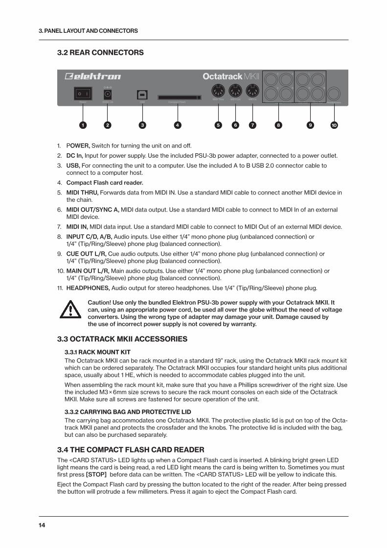
1 2 3 4 5 6 7 108 9
1. POWER, Switch for turning the unit on and off.
2. DC In, Input for power supply. Use the included PSU-3b power adapter, connected to a power outlet.
3. USB, For connecting the unit to a computer. Use the included A to B USB 2.0 connector cable to connect to a computer host.
4. Compact Flash card reader.
5. MIDI THRU, Forwards data from MIDI IN. Use a standard MIDI cable to connect another MIDI device in the chain.
6. MIDI OUT/SYNC A, MIDI data output. Use a standard MIDI cable to connect to MIDI In of an external MIDI device.
7. MIDI IN, MIDI data input. Use a standard MIDI cable to connect to MIDI Out of an external MIDI device.
8. INPUT C/D, A/B, Audio inputs. Use either 1/4” mono phone plug (unbalanced connection) or 1/4” (Tip/Ring/Sleeve) phone plug (balanced connection).
9. CUE OUT L/R, Cue audio outputs. Use either 1/4” mono phone plug (unbalanced connection) or 1/4” (Tip/Ring/Sleeve) phone plug (balanced connection).
10. MAIN OUT L/R, Main audio outputs. Use either 1/4” mono phone plug (unbalanced connection) or 1/4” (Tip/Ring/Sleeve) phone plug (balanced connection).
11. HEADPHONES, Audio output for stereo headphones. Use 1/4” (Tip/Ring/Sleeve) phone plug.
Caution! Use only the bundled Elektron PSU-3b power supply with your Octatrack MKII. It can, using an appropriate power cord, be used all over the globe without the need of voltage converters. Using the wrong type of adapter may damage your unit. Damage caused by the use of incorrect power supply is not covered by warranty.
3.3 OCTATRACK MKII ACCESSORIES
3.3.1 RACK MOUNT KITThe Octatrack MKII can be rack mounted in a standard 19” rack, using the Octatrack MKII rack mount kit which can be ordered separately. The Octatrack MKII occupies four standard height units plus additional space, usually about 1 HE, which is needed to accommodate cables plugged into the unit.
When assembling the rack mount kit, make sure that you have a Phillips screwdriver of the right size. Use the included M3 × 6mm size screws to secure the rack mount consoles on each side of the Octatrack MKII. Make sure all screws are fastened for secure operation of the unit.
3.3.2 CARRYING BAG AND PROTECTIVE LIDThe carrying bag accommodates one Octatrack MKII. The protective plastic lid is put on top of the Octa-track MKII panel and protects the crossfader and the knobs. The protective lid is included with the bag, but can also be purchased separately.
3.4 THE COMPACT FLASH CARD READERThe <CARD STATUS> LED lights up when a Compact Flash card is inserted. A blinking bright green LED light means the card is being read, a red LED light means the card is being written to. Sometimes you must first press [STOP] before data can be written. The <CARD STATUS> LED will be yellow to indicate this.
Eject the Compact Flash card by pressing the button located to the right of the reader. After being pressed the button will protrude a few millimeters. Press it again to eject the Compact Flash card.
3. PANEL LAYOUT AND CONNECTORS
15
3.4.1 COMPACT FLASH CARD SPECIFICATIONSCards supporting UDMA and at least 133x (~20MB/s) for both reads and writes are compatible with the Octatrack MKII. Cards must be FAT16 or FAT32 formatted, preferably FAT32. Up to 64 GB Compact Flash cards are supported.
Never remove the card while data is being read or written to the it. Doing so might cor-rupt files and data. The card should only be removed when the <CARD STATUS> LED is dimmed green and shines with a steady light.
3.5 CONNECTING THE UNITBefore you start connecting the Octatrack MKII to other units, make sure all units are switched off.
1. Plug the supplied DC adapter to a power outlet and connect the small plug to the 12 V DC connector of the Octatrack MKII unit.
2. Connect the main out L/R from the Octatrack MKII to your mixer or amplifier.
3. If you want to use MIDI, connect MIDI OUT from the Octatrack MKII to the MIDI IN of the device you wish to send data to. Connect the MIDI IN of the Octatrack MKII to the MIDI OUT of the device you wish to receive data from. The MIDI THRU port “echoes” the data arriving at the MIDI IN port, and is used for chaining MIDI units together.
4. Switch on all units.
The USB connection may inject computer noise in the outputs of the Octatrack MKII. Should this occur, use balanced cables or use a battery operated computer. Do not remove the safe-ty grounding of your computer. It is there to protect against electric shocks.
3.6 CARE INSTRUCTIONSTo ensure many years of trouble free operation, please follow the advice below:
• Never use any aggressive cleaners on the casing or the screen overlay. Remove dust, dirt and finger-prints with a soft dry cloth. More persistent dirt can be removed with a slightly damp cloth using only water.
• To avoid scratches or damage, never use sharp objects near the display. Also avoid applying any pres-sure to the display itself.
• When transporting the Octatrack MKII, use the box and padding the unit originally shipped with or the Elektron Carry Bag ECC-2.
• Make sure you place the unit on a stable surface before use. If you mount the unit in a rack, be sure to tighten all four screws in the rack mount holes.
• The memory used for storing patterns and parts is powered by a battery inside the unit. It will hold data at least 6 years before needing replacement. If the battery needs replacement, a “BATTERY LOW” mes-sage will appear in the display. Contact Elektron support or your nearest repair center.
• Use the power switch to turn off the machine when it is not in use.

4. OVERVIEW OF THE OCTATRACK MKII STRUCTURE
16
4. OVERVIEW OF THE OCTATRACK MKII STRUCTUREThe Octatrack MKII is organized in a hierarchical way. The image below outlines the data structure of the Octatrack MKII.
Set
Audio Pool
Project
Banks
Parts
Flex Sample Slots
Machine AssignmentE�ects Assignment
Static Sample Slots
Track ParametersScenes
Patterns
Arrangements
4.1 SETSA set is the top level structure of the Octatrack MKII. It can contain a near unlimited amount of projects plus one audio pool. The number of samples in the audio pool, as well as the number of projects, are limited only by the size of the Compact Flash card. The samples in the audio pool are available to all projects of the set. Sets are saved on the Compact Flash card. Since a set can contain many projects, some users might find that one set is all they need. For more information, please see “7. SETS” on page 26.
4.2 AUDIO POOLEach set contains one audio pool which is stored on the Compact Flash card. The audio pool contains the samples that can be loaded to the Flex and Static sample slot lists of the projects of a set. For more infor-mation, please see “7.2.1 ADDING CONTENT TO THE AUDIO POOL” on page 27.
4.3 PROJECTSFor the Octatrack MKII to work as intended, a set needs to be mounted and a project needs to be loaded. A project contains 16 banks, 8 arrangements, 8 track recorders and their recorder buffers, 128 sample slots dedicated to Flex machines, 128 slots dedicated to Static machines, various project specific settings and the BPM setting for all the patterns of the project.
The samples used to fill the Flex and Static sample slots are fetched from the audio pool of the set. The samples used by a project can also be collected and saved in the project folder. The command COLLECT SAMPLES are used for this and makes a project more or less self contained. For the sake of sample or-ganization it is recommended to only store samples in the audio pool. For more information, please see “8. PROJECTS” on page 28.
4. OVERVIEW OF THE OCTATRACK MKII STRUCTURE
17
4.4 FLEX AND STATIC SAMPLE SLOT LISTSFor samples to be available to Flex and Static machines they first need to be loaded from the audio pool to the Flex or Static sample slot lists. When samples are present in these lists they can be assigned to, and thus processed by, Flex and Static machines assigned to the audio tracks of a pattern. Read how to load audio pool samples to the sample slot lists in the section “8.3 LOADING SAMPLES TO THE SAMPLE SLOTS” on page 29. Read how to assign samples to a machine in the section “11.3 ASSIGNING FLEX AND STATIC SAMPLES TO MACHINES” on page 56.
4.5 BANKSEach project hosts 16 banks and each bank hosts 16 patterns and 4 parts. This makes a bank suited for hosting a complete composition as the available patterns and parts allow a large number of song variations. Switching between banks is seamless, meaning playback won’t be halted or audio cut off. For more informa-tion, please see “10.1 BANKS” on page 52.
4.6 PATTERNSFor each bank 16 patterns are available, meaning 256 patterns are always at hand. A pattern consists of sequencer data like trigs, parameter locks, track lengths and time signatures for the eight audio tracks and the eight MIDI tracks. For more information, please see “12. PATTERNS” on page 64.
4.7 PARTS4 parts are available to each bank. A part contains machine assignments and their associated samples, track parameter settings, FX assignments as well as 16 scenes. A pattern is always linked to a part. Chang-ing parts will let the active pattern control the new part. For more information, please see “10.2 PARTS” on page 52.
4.8 SCENESScenes are assigned to the scene A and scene B slots. They decide which parameters the crossfader will affect. For more information, please see “10.3 SCENES” on page 53.
4.9 ARRANGEMENTSEach project contains eight arrangements. They are used to structure the playback of patterns. An arrange-ment is a great way to form a long sequence out of several patterns. For more information, please see “14. THE ARRANGER” on page 86.
4.10 TRACKSAn Octatrack MKII pattern handles eight audio tracks and eight MIDI tracks. Each audio track can host a machine. Except for Neighbor machines, any machine type can be assigned to any of the eight audio tracks. For more information, please see “11. TRACKS” on page 55.
4.11 MACHINESMachines are assigned to the eight audio tracks. Each machine fills a different purpose. Read more about the various machine types in “APPENDIX A: MACHINE REFERENCE” on page 116. How machines are assigned to tracks is covered in “11.2 ASSIGNING MACHINES TO TRACKS” on page 55.
Flex machines process samples. They offer instant control over samples since Flex samples are loaded into the RAM memory of the Octatrack MKII. The samples available to Flex machines are located in the Flex sample slot list, which can host 128 Flex samples.
Static machines process samples. The samples available to Static machines are located in the Static sample slot list, which can host 128 Static samples streamed from the Compact Flash card. A single Static sample can be as big as 2 gigabytes.
Thru machines are used to listen to the inputs of the Octatrack MKII. They can be used to affect incoming audio with filtering and effects.
Neighbor machines listen to the output of the preceding track. They can be used to build powerful effects chains.
Pickup machines are ideal when wanting to use the Octatrack MKII as a looper device.

4. OVERVIEW OF THE OCTATRACK MKII STRUCTURE
18
4.12 HOW INFORMATION IS HANDLEDWhen working within a project there is no need to save as all changes are automatically cached on card. Changes made to a project will be remembered even after the machine has been switched off. The only time an operation needs to be carried out is before removing the Compact Flash card. The project should then be synced to the card. For more information about this operation, please see page 30.
There exists a SAVE command for projects though. Once you are content with a project, it is wise to save it. If you continue your work with the project, but are not satisfied with the results, you can then bring back the project to the previously saved state by performing a project RELOAD command. For more information, please see “8.4.1 PROJECT” on page 31.
Never turn off the Octatrack MKII while the <CARD STATUS> LED is blinking. It indicates data is being written to the Compact Flash card and disrupting this process may corrupt data. Only when the <CARD STATUS> LED emits a dimmed green and steady light the Octatrack MKII might be switched off.
5. THE USER INTERFACE
19
5. THE USER INTERFACEThe screen is the information center of the Octatrack MKII editing. The main interface screen is shown below:
1 2 43 5 6
9 810 711
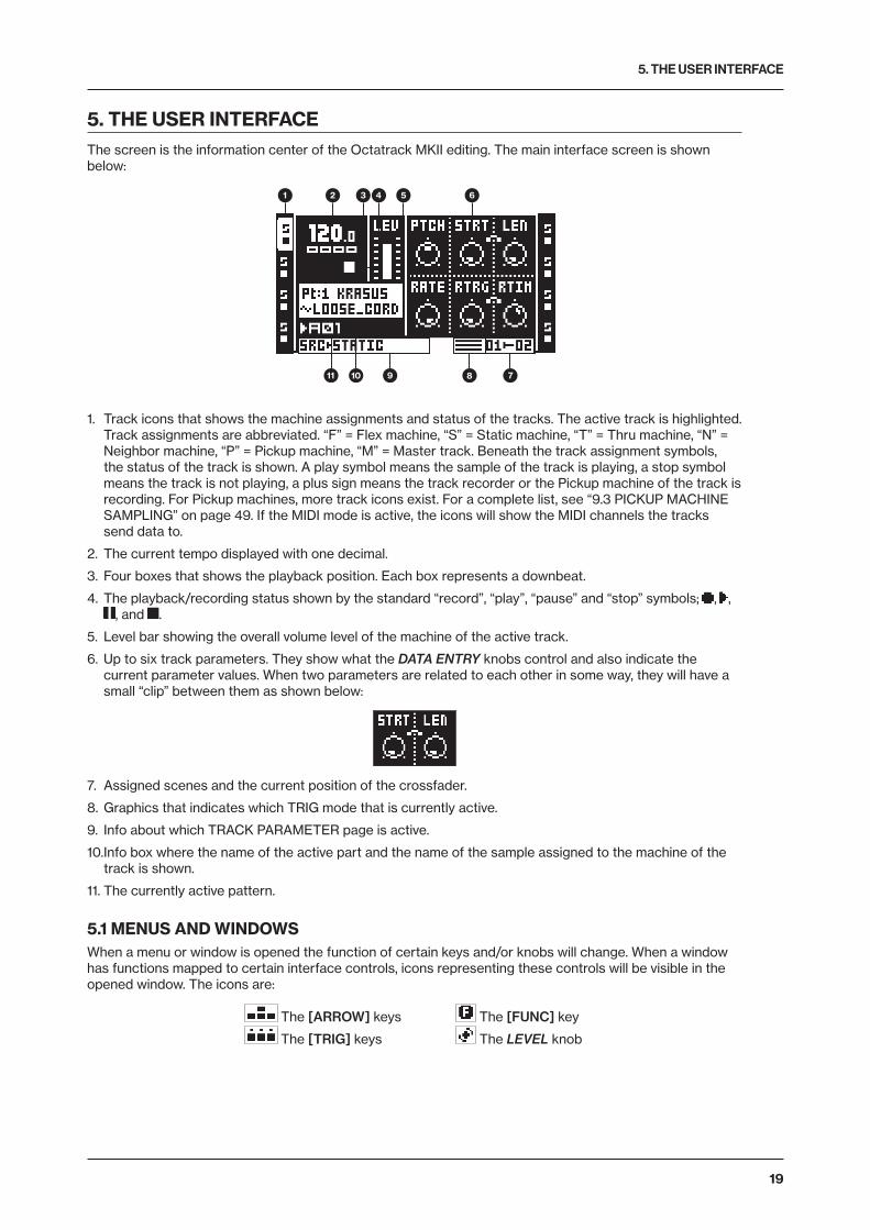
1. Track icons that shows the machine assignments and status of the tracks. The active track is highlighted. Track assignments are abbreviated. “F” = Flex machine, “S” = Static machine, “T” = Thru machine, “N” = Neighbor machine, “P” = Pickup machine, “M” = Master track. Beneath the track assignment symbols, the status of the track is shown. A play symbol means the sample of the track is playing, a stop symbol means the track is not playing, a plus sign means the track recorder or the Pickup machine of the track is recording. For Pickup machines, more track icons exist. For a complete list, see “9.3 PICKUP MACHINE SAMPLING” on page 49. If the MIDI mode is active, the icons will show the MIDI channels the tracks send data to.
2. The current tempo displayed with one decimal.
3. Four boxes that shows the playback position. Each box represents a downbeat.
4. The playback/recording status shown by the standard “record”, “play”, “pause” and “stop” symbols; , , , and .
5. Level bar showing the overall volume level of the machine of the active track.
6. Up to six track parameters. They show what the DATA ENTRY knobs control and also indicate the current parameter values. When two parameters are related to each other in some way, they will have a small “clip” between them as shown below:
7. Assigned scenes and the current position of the crossfader.
8. Graphics that indicates which TRIG mode that is currently active.
9. Info about which TRACK PARAMETER page is active.
10. Info box where the name of the active part and the name of the sample assigned to the machine of the track is shown.
11. The currently active pattern.
5.1 MENUS AND WINDOWSWhen a menu or window is opened the function of certain keys and/or knobs will change. When a window has functions mapped to certain interface controls, icons representing these controls will be visible in the opened window. The icons are:
The [ARROW] keys The [FUNC] key
The [TRIG] keys The LEVEL knob
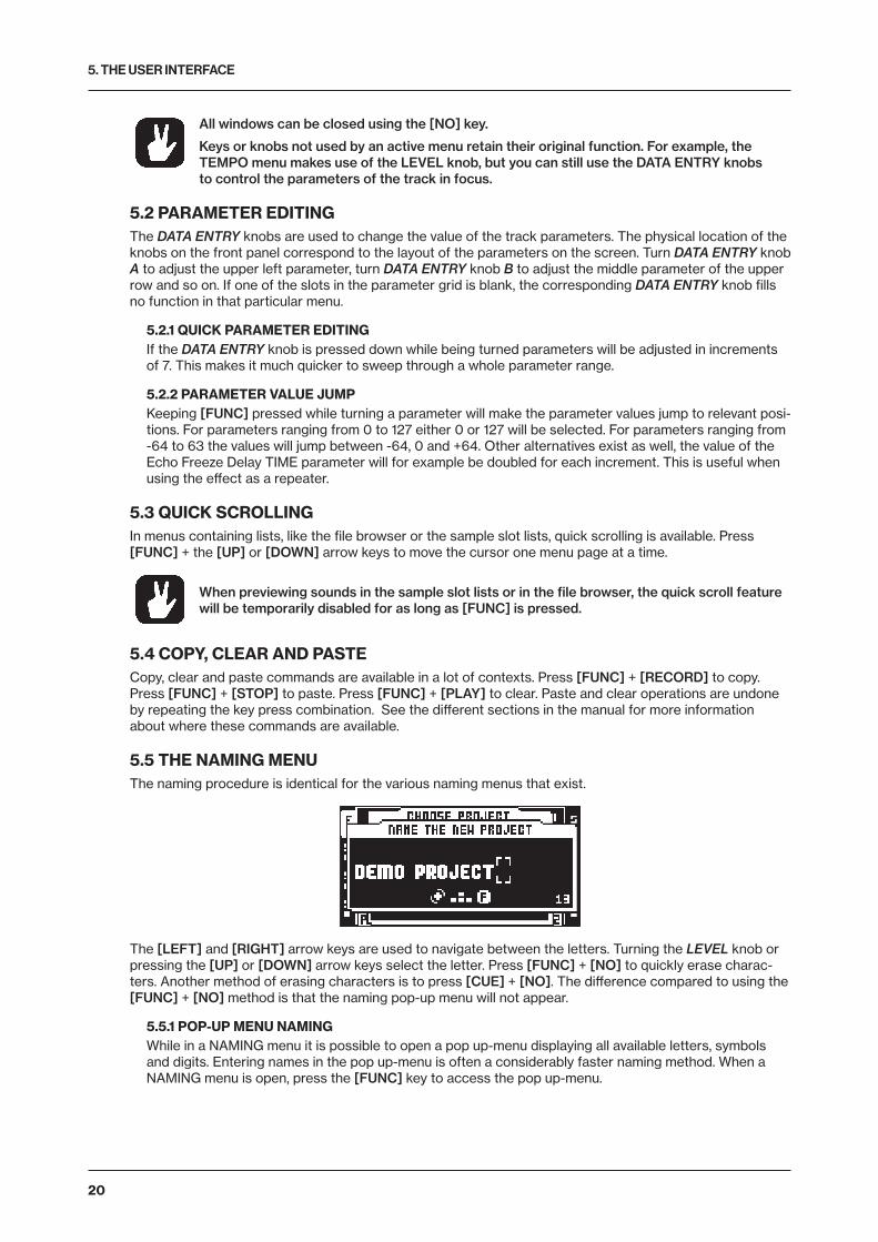
5. THE USER INTERFACE
20
All windows can be closed using the [NO] key.
Keys or knobs not used by an active menu retain their original function. For example, the TEMPO menu makes use of the LEVEL knob, but you can still use the DATA ENTRY knobs to control the parameters of the track in focus.
5.2 PARAMETER EDITINGThe DATA ENTRY knobs are used to change the value of the track parameters. The physical location of the knobs on the front panel correspond to the layout of the parameters on the screen. Turn DATA ENTRY knob A to adjust the upper left parameter, turn DATA ENTRY knob B to adjust the middle parameter of the upper row and so on. If one of the slots in the parameter grid is blank, the corresponding DATA ENTRY knob fills no function in that particular menu.
5.2.1 QUICK PARAMETER EDITINGIf the DATA ENTRY knob is pressed down while being turned parameters will be adjusted in increments of 7. This makes it much quicker to sweep through a whole parameter range.
5.2.2 PARAMETER VALUE JUMPKeeping [FUNC] pressed while turning a parameter will make the parameter values jump to relevant posi-tions. For parameters ranging from 0 to 127 either 0 or 127 will be selected. For parameters ranging from -64 to 63 the values will jump between -64, 0 and +64. Other alternatives exist as well, the value of the Echo Freeze Delay TIME parameter will for example be doubled for each increment. This is useful when using the effect as a repeater.
5.3 QUICK SCROLLINGIn menus containing lists, like the file browser or the sample slot lists, quick scrolling is available. Press [FUNC] + the [UP] or [DOWN] arrow keys to move the cursor one menu page at a time.
When previewing sounds in the sample slot lists or in the file browser, the quick scroll feature will be temporarily disabled for as long as [FUNC] is pressed.
5.4 COPY, CLEAR AND PASTECopy, clear and paste commands are available in a lot of contexts. Press [FUNC] + [RECORD] to copy. Press [FUNC] + [STOP] to paste. Press [FUNC] + [PLAY] to clear. Paste and clear operations are undone by repeating the key press combination. See the different sections in the manual for more information about where these commands are available.
5.5 THE NAMING MENUThe naming procedure is identical for the various naming menus that exist.
The [LEFT] and [RIGHT] arrow keys are used to navigate between the letters. Turning the LEVEL knob or pressing the [UP] or [DOWN] arrow keys select the letter. Press [FUNC] + [NO] to quickly erase charac-ters. Another method of erasing characters is to press [CUE] + [NO]. The difference compared to using the [FUNC] + [NO] method is that the naming pop-up menu will not appear.
5.5.1 POP-UP MENU NAMINGWhile in a NAMING menu it is possible to open a pop up-menu displaying all available letters, symbols and digits. Entering names in the pop up-menu is often a considerably faster naming method. When a NAMING menu is open, press the [FUNC] key to access the pop up-menu.
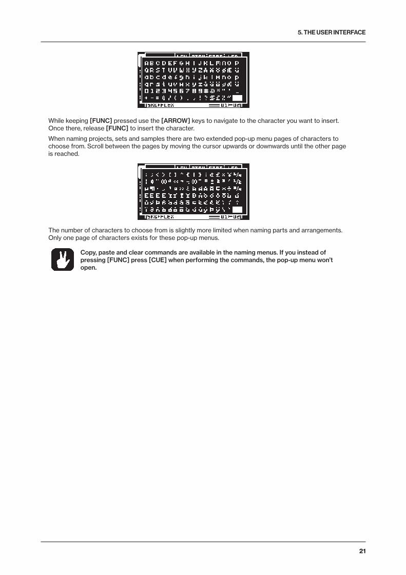
5. THE USER INTERFACE
21
While keeping [FUNC] pressed use the [ARROW] keys to navigate to the character you want to insert. Once there, release [FUNC] to insert the character.
When naming projects, sets and samples there are two extended pop-up menu pages of characters to choose from. Scroll between the pages by moving the cursor upwards or downwards until the other page is reached.
The number of characters to choose from is slightly more limited when naming parts and arrangements. Only one page of characters exists for these pop-up menus.
Copy, paste and clear commands are available in the naming menus. If you instead of pressing [FUNC] press [CUE] when performing the commands, the pop-up menu won’t open.
6. QUICK START
22
6. QUICK STARTThis quick start will guide you through some of the basic operations to allow you to start using the Octatrack MKII. First connect it as described in section “3.5 CONNECTING THE UNIT” on page 15.
6.1 DEMO MODEIn demo mode, the Octatrack MKII can play back a set of 16 demo patterns without needing to have a Compact Flash card inserted. Demo mode is a great way to get acquainted with the basics of the Octatrack MKII. Note that you can not save any changes made to the sounds or patterns while in demo mode.
1. Make sure no Compact Flash card is inserted. Press and hold the [YES] key and then switch on the Octatrack MKII. The screen shows that you are entering demo mode..
6.1.1 PLAYING THE DEMO PATTERNSIn demo mode, 16 demo patterns (A01–A16) are available.
1. Press [PLAY] to listen to pattern A01.
2. Select pattern A02, which is the second demo pattern, by pressing [PTN] + [TRIG] key 2. Pattern A03 is selected by pressing [PTN] + [TRIG] key 3 and so on.
3. Mute tracks by pressing [FUNC] + the [TRACK] key of the track you want to mute. Unmute by repeat-ing the procedure.
6.1.2 ADJUSTING PARAMETERSEach track contains five TRACK PARAMETER pages. Here you find the parameters that affects the sam-ple of the track. The keys used to open the pages are located directly below the screen.
1. Make sure the pattern is still playing.
2. Press the [TRACK] key of the track whose sample you wish to affect.
3. To change the pitch of the sample, press the [SRC] key. The SRC page will open. The parameter labeled PTCH changes the pitch of the sample. Turn DATA ENTRY knob A to change the parameter value.
4. Try out the rest of the TRACK PARAMETER menu parameters to experiment with the sound shaping possibilities.
5. To reload the parameter settings to their original state, press [FUNC] + [CUE].
6.1.3 EXPERIMENTING WITH SCENESScenes contain locked parameters. The crossfader is used to morph between the locked scene parame-ters. Scenes are covered in the section ”4.8 SCENES” on page 17.
1. Select any demo pattern. Set the crossfader to its rightmost position. This will fully activate the scene assigned to scene slot B.
2. Hold [SCENE B] and press a [TRIG] key to assign a new scene to the scene slot. The already as-signed scene is indicated by a red [TRIG] key. Experiment with assigning different scenes to the scene slot and listen to how the sound of the pattern changes.
6.1.4 RECORDING A PATTERN USING GRID RECORDINGUse GRID RECORDING mode to input sample trigs to the sequencer. Sample trigs trig the machines and samples of the tracks. In depth information about this mode is found in section “12.3.1 GRID RECORDING MODE” on page 65.
1. Press the [RECORD] key to enter GRID RECORDING mode. The [RECORD] key will light up, indicat-ing the mode is now active.
2. Select the track to which you want to input sample trigs by pressing the relevant [TRACK] key.
3. Press a [TRIG] key to enter a sample trig. Press the same [TRIG] key again to remove the sample trig. If the pattern contains more than 16 steps, use the [PAGE] key to switch between the pattern pages.
4. To edit other tracks, change the active track by pressing the other [TRACK] keys.
6.1.5 RECORDING A PATTERN USING LIVE RECORDINGThe LIVE RECORDING mode allows you to record sample trigs and parameter changes while the se-quencer is running. In depth information about this mode is found in section”12.3.2 LIVE RECORDING MODE” on page 65.
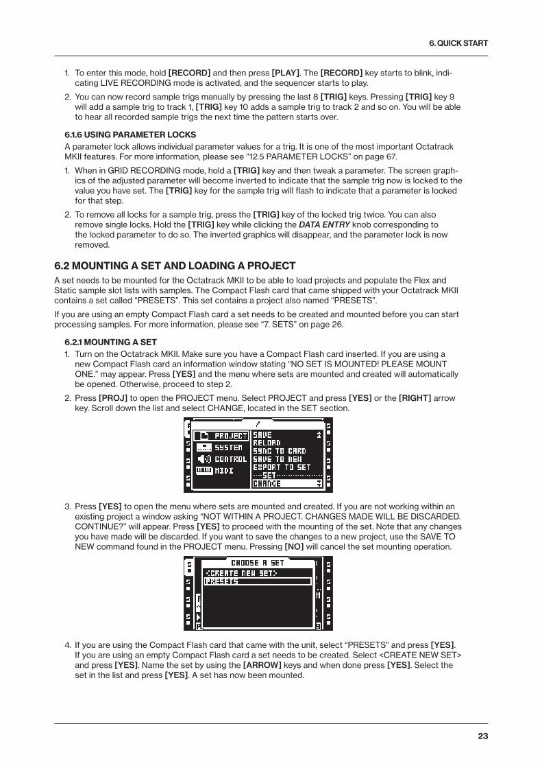
6. QUICK START
23
1. To enter this mode, hold [RECORD] and then press [PLAY]. The [RECORD] key starts to blink, indi-cating LIVE RECORDING mode is activated, and the sequencer starts to play.
2. You can now record sample trigs manually by pressing the last 8 [TRIG] keys. Pressing [TRIG] key 9 will add a sample trig to track 1, [TRIG] key 10 adds a sample trig to track 2 and so on. You will be able to hear all recorded sample trigs the next time the pattern starts over.
6.1.6 USING PARAMETER LOCKSA parameter lock allows individual parameter values for a trig. It is one of the most important Octatrack MKII features. For more information, please see “12.5 PARAMETER LOCKS” on page 67.
1. When in GRID RECORDING mode, hold a [TRIG] key and then tweak a parameter. The screen graph-ics of the adjusted parameter will become inverted to indicate that the sample trig now is locked to the value you have set. The [TRIG] key for the sample trig will flash to indicate that a parameter is locked for that step.
2. To remove all locks for a sample trig, press the [TRIG] key of the locked trig twice. You can also remove single locks. Hold the [TRIG] key while clicking the DATA ENTRY knob corresponding to the locked parameter to do so. The inverted graphics will disappear, and the parameter lock is now removed.
6.2 MOUNTING A SET AND LOADING A PROJECTA set needs to be mounted for the Octatrack MKII to be able to load projects and populate the Flex and Static sample slot lists with samples. The Compact Flash card that came shipped with your Octatrack MKII contains a set called “PRESETS”. This set contains a project also named “PRESETS”.
If you are using an empty Compact Flash card a set needs to be created and mounted before you can start processing samples. For more information, please see “7. SETS” on page 26.
6.2.1 MOUNTING A SET1. Turn on the Octatrack MKII. Make sure you have a Compact Flash card inserted. If you are using a
new Compact Flash card an information window stating “NO SET IS MOUNTED! PLEASE MOUNT ONE.” may appear. Press [YES] and the menu where sets are mounted and created will automatically be opened. Otherwise, proceed to step 2.
2. Press [PROJ] to open the PROJECT menu. Select PROJECT and press [YES] or the [RIGHT] arrow key. Scroll down the list and select CHANGE, located in the SET section.
3. Press [YES] to open the menu where sets are mounted and created. If you are not working within an existing project a window asking “NOT WITHIN A PROJECT. CHANGES MADE WILL BE DISCARDED. CONTINUE?” will appear. Press [YES] to proceed with the mounting of the set. Note that any changes you have made will be discarded. If you want to save the changes to a new project, use the SAVE TO NEW command found in the PROJECT menu. Pressing [NO] will cancel the set mounting operation.
4. If you are using the Compact Flash card that came with the unit, select “PRESETS” and press [YES]. If you are using an empty Compact Flash card a set needs to be created. Select <CREATE NEW SET> and press [YES]. Name the set by using the [ARROW] keys and when done press [YES]. Select the set in the list and press [YES]. A set has now been mounted.
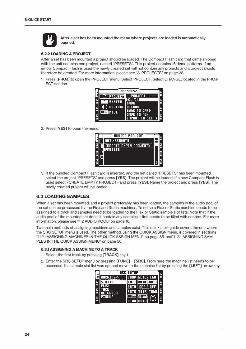
6. QUICK START
24
After a set has been mounted the menu where projects are loaded is automatically opened.
6.2.2 LOADING A PROJECTAfter a set has been mounted a project should be loaded. The Compact Flash card that came shipped with the unit contains one project, named “PRESETS”. This project contains 16 demo patterns. If an empty Compact Flash is used the newly created set will not contain any projects and a project should therefore be created. For more information, please see “8. PROJECTS” on page 28.
1. Press [PROJ] to open the PROJECT menu. Select PROJECT. Select CHANGE, located in the PROJ-ECT section.
2. Press [YES] to open the menu.
3. If the bundled Compact Flash card is inserted, and the set called “PRESETS” has been mounted, select the project “PRESETS” and press [YES]. The project will be loaded. If a new Compact Flash is used select <CREATE EMPTY PROJECT> and press [YES]. Name the project and press [YES]. The newly created project will be loaded.
6.3 LOADING SAMPLESWhen a set has been mounted, and a project preferably has been loaded, the samples in the audio pool of the set can be processed by the Flex and Static machines. To do so a Flex or Static machine needs to be assigned to a track and samples need to be loaded to the Flex or Static sample slot lists. Note that if the audio pool of the mounted set doesn’t contain any samples it first needs to be filled with content. For more information, please see “4.2 AUDIO POOL” on page 16.
Two main methods of assigning machines and samples exist. This quick start guide covers the one where the SRC SETUP menu is used. The other method, using the QUICK ASSIGN menu, is covered in sections “11.2.1 ASSIGNING MACHINES IN THE QUICK ASSIGN MENU” on page 55. and”11.3.1 ASSIGNING SAM-PLES IN THE QUICK ASSIGN MENU” on page 56.
6.3.1 ASSIGNING A MACHINE TO A TRACK1. Select the first track by pressing [TRACK] key 1.
2. Enter the SRC SETUP menu by pressing [FUNC] + [SRC]. From here the machine list needs to be accessed. If a sample slot list was opened move to the machine list by pressing the [LEFT] arrow key.
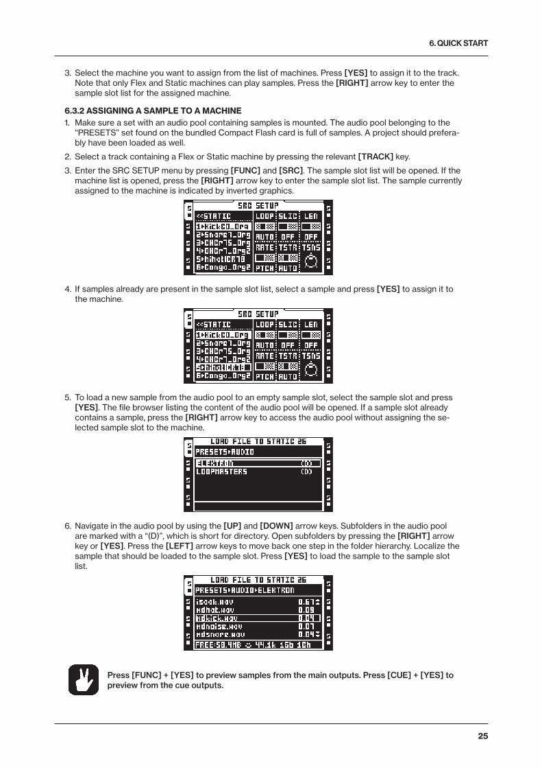
6. QUICK START
25
3. Select the machine you want to assign from the list of machines. Press [YES] to assign it to the track. Note that only Flex and Static machines can play samples. Press the [RIGHT] arrow key to enter the sample slot list for the assigned machine.
6.3.2 ASSIGNING A SAMPLE TO A MACHINE1. Make sure a set with an audio pool containing samples is mounted. The audio pool belonging to the
“PRESETS” set found on the bundled Compact Flash card is full of samples. A project should prefera-bly have been loaded as well.
2. Select a track containing a Flex or Static machine by pressing the relevant [TRACK] key.
3. Enter the SRC SETUP menu by pressing [FUNC] and [SRC]. The sample slot list will be opened. If the machine list is opened, press the [RIGHT] arrow key to enter the sample slot list. The sample currently assigned to the machine is indicated by inverted graphics.
4. If samples already are present in the sample slot list, select a sample and press [YES] to assign it to the machine.
5. To load a new sample from the audio pool to an empty sample slot, select the sample slot and press [YES]. The file browser listing the content of the audio pool will be opened. If a sample slot already contains a sample, press the [RIGHT] arrow key to access the audio pool without assigning the se-lected sample slot to the machine.
6. Navigate in the audio pool by using the [UP] and [DOWN] arrow keys. Subfolders in the audio pool are marked with a “(D)”, which is short for directory. Open subfolders by pressing the [RIGHT] arrow key or [YES]. Press the [LEFT] arrow keys to move back one step in the folder hierarchy. Localize the sample that should be loaded to the sample slot. Press [YES] to load the sample to the sample slot list.
Press [FUNC] + [YES] to preview samples from the main outputs. Press [CUE] + [YES] to preview from the cue outputs.
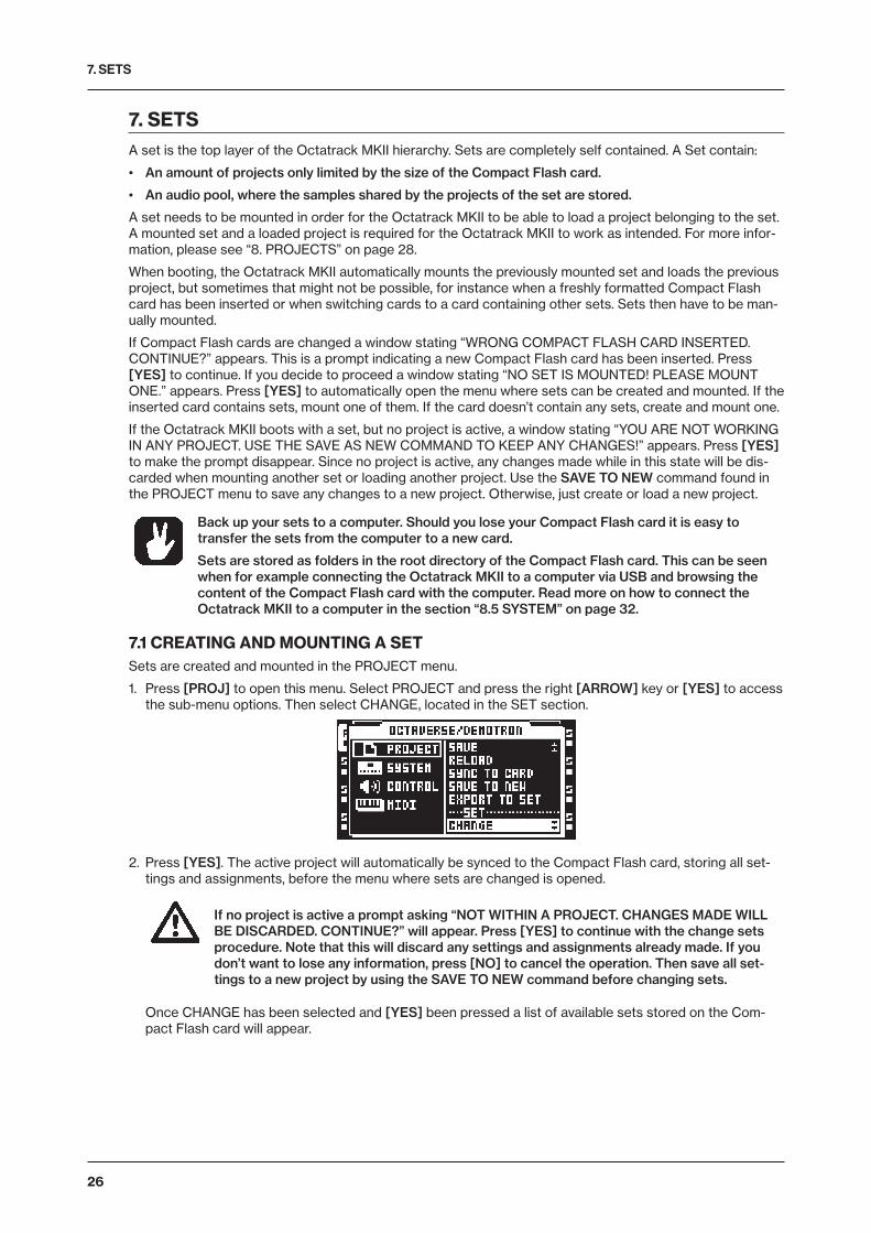
7. SETS
26
7. SETSA set is the top layer of the Octatrack MKII hierarchy. Sets are completely self contained. A Set contain:
• An amount of projects only limited by the size of the Compact Flash card.
• An audio pool, where the samples shared by the projects of the set are stored.
A set needs to be mounted in order for the Octatrack MKII to be able to load a project belonging to the set. A mounted set and a loaded project is required for the Octatrack MKII to work as intended. For more infor-mation, please see “8. PROJECTS” on page 28.
When booting, the Octatrack MKII automatically mounts the previously mounted set and loads the previous project, but sometimes that might not be possible, for instance when a freshly formatted Compact Flash card has been inserted or when switching cards to a card containing other sets. Sets then have to be man-ually mounted.
If Compact Flash cards are changed a window stating “WRONG COMPACT FLASH CARD INSERTED. CONTINUE?” appears. This is a prompt indicating a new Compact Flash card has been inserted. Press [YES] to continue. If you decide to proceed a window stating “NO SET IS MOUNTED! PLEASE MOUNT ONE.” appears. Press [YES] to automatically open the menu where sets can be created and mounted. If the inserted card contains sets, mount one of them. If the card doesn’t contain any sets, create and mount one.
If the Octatrack MKII boots with a set, but no project is active, a window stating “YOU ARE NOT WORKING IN ANY PROJECT. USE THE SAVE AS NEW COMMAND TO KEEP ANY CHANGES!” appears. Press [YES] to make the prompt disappear. Since no project is active, any changes made while in this state will be dis-carded when mounting another set or loading another project. Use the SAVE TO NEW command found in the PROJECT menu to save any changes to a new project. Otherwise, just create or load a new project.
Back up your sets to a computer. Should you lose your Compact Flash card it is easy to transfer the sets from the computer to a new card.
Sets are stored as folders in the root directory of the Compact Flash card. This can be seen when for example connecting the Octatrack MKII to a computer via USB and browsing the content of the Compact Flash card with the computer. Read more on how to connect the Octatrack MKII to a computer in the section “8.5 SYSTEM” on page 32.
7.1 CREATING AND MOUNTING A SETSets are created and mounted in the PROJECT menu.
1. Press [PROJ] to open this menu. Select PROJECT and press the right [ARROW] key or [YES] to access the sub-menu options. Then select CHANGE, located in the SET section.
2. Press [YES]. The active project will automatically be synced to the Compact Flash card, storing all set-tings and assignments, before the menu where sets are changed is opened.
If no project is active a prompt asking “NOT WITHIN A PROJECT. CHANGES MADE WILL BE DISCARDED. CONTINUE?” will appear. Press [YES] to continue with the change sets procedure. Note that this will discard any settings and assignments already made. If you don’t want to lose any information, press [NO] to cancel the operation. Then save all set-tings to a new project by using the SAVE TO NEW command before changing sets.
Once CHANGE has been selected and [YES] been pressed a list of available sets stored on the Com-pact Flash card will appear.
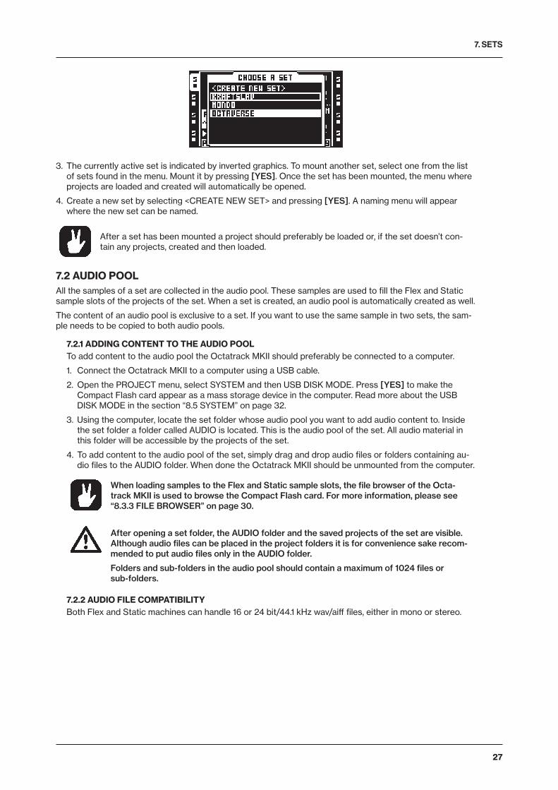
7. SETS
27
3. The currently active set is indicated by inverted graphics. To mount another set, select one from the list of sets found in the menu. Mount it by pressing [YES]. Once the set has been mounted, the menu where projects are loaded and created will automatically be opened.
4. Create a new set by selecting <CREATE NEW SET> and pressing [YES]. A naming menu will appear where the new set can be named.
After a set has been mounted a project should preferably be loaded or, if the set doesn’t con-tain any projects, created and then loaded.
7.2 AUDIO POOLAll the samples of a set are collected in the audio pool. These samples are used to fill the Flex and Static sample slots of the projects of the set. When a set is created, an audio pool is automatically created as well.
The content of an audio pool is exclusive to a set. If you want to use the same sample in two sets, the sam-ple needs to be copied to both audio pools.
7.2.1 ADDING CONTENT TO THE AUDIO POOLTo add content to the audio pool the Octatrack MKII should preferably be connected to a computer.
1. Connect the Octatrack MKII to a computer using a USB cable.
2. Open the PROJECT menu, select SYSTEM and then USB DISK MODE. Press [YES] to make the Compact Flash card appear as a mass storage device in the computer. Read more about the USB DISK MODE in the section “8.5 SYSTEM” on page 32.
3. Using the computer, locate the set folder whose audio pool you want to add audio content to. Inside the set folder a folder called AUDIO is located. This is the audio pool of the set. All audio material in this folder will be accessible by the projects of the set.
4. To add content to the audio pool of the set, simply drag and drop audio files or folders containing au-dio files to the AUDIO folder. When done the Octatrack MKII should be unmounted from the computer.
When loading samples to the Flex and Static sample slots, the file browser of the Octa-track MKII is used to browse the Compact Flash card. For more information, please see “8.3.3 FILE BROWSER” on page 30.
After opening a set folder, the AUDIO folder and the saved projects of the set are visible. Although audio files can be placed in the project folders it is for convenience sake recom-mended to put audio files only in the AUDIO folder.
Folders and sub-folders in the audio pool should contain a maximum of 1024 files or sub-folders.
7.2.2 AUDIO FILE COMPATIBILITYBoth Flex and Static machines can handle 16 or 24 bit/44.1 kHz wav/aiff files, either in mono or stereo.
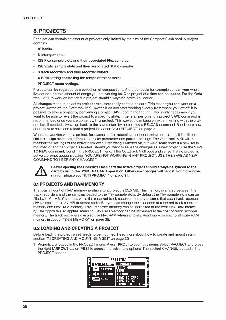
8. PROJECTS
28
8. PROJECTSEach set can contain an amount of projects only limited by the size of the Compact Flash card. A project contains:
• 16 banks.
• 8 arrangements.
• 128 Flex sample slots and their associated Flex samples.
• 128 Static sample slots and their associated Static samples.
• 8 track recorders and their recorder buffers.
• A BPM setting controlling the tempo of the patterns.
• PROJECT menu settings.
Projects can be regarded as a collection of compositions. A project could for example contain your whole live set or a certain amount of songs you are working on. One project at a time can be loaded. For the Octa-track MKII to work as intended, a project should always be active, i.e. loaded.
All changes made to an active project are automatically cached on card. This means you can work on a project, switch off the Octatrack MKII, switch it on and start working exactly from where you left off. It is possible to save a project by performing a project SAVE command though. This is only necessary if you want to be able to revert the project to a specific state. In general, performing a project SAVE command is recommended once you are content with a project. This way you can keep on experimenting with the proj-ect, but, if needed, always go back to the saved state by performing a RELOAD command. Read more how about how to save and reload a project in section “8.4.1 PROJECT” on page 31.
When not working within a project, for example after mounting a set containing no projects, it is still pos-sible to assign machines, effects and make parameter and pattern settings. The Octatrack MKII will re-member the settings of the active bank even after being switched off, but will discard them if a new set is mounted or another project is loaded. Should you want to save the changes as a new project, use the SAVE TO NEW command, found in the PROJECT menu. If the Octatrack MKII boot and sense that no project is active a prompt appears saying “YOU ARE NOT WORKING IN ANY PROJECT. USE THE SAVE AS NEW COMMAND TO KEEP ANY CHANGES!”
Before ejecting the Compact Flash card the active project should always be synced to the card, by using the SYNC TO CARD operation. Otherwise changes will be lost. For more infor-mation, please see “8.4.1 PROJECT” on page 31.
8.1 PROJECTS AND RAM MEMORYThe total amount of RAM memory available to a project is 85,5 MB. This memory is shared between the track recorders and the samples loaded to the Flex sample slots. By default the Flex sample slots can be filled with 64 MB of samples while the reserved track recorder memory ensures that each track recorder always can sample 2.7 MB of stereo audio. But you can change the allocation of reserved track recorder memory and Flex RAM memory. Track recorder memory can be increased at the cost Flex RAM memo-ry. The opposite also applies, meaning Flex RAM memory can be increased at the cost of track recorder memory. The track recorders can also use Flex RAM when sampling. Read more on how to allocate RAM memory in section “8.6.5 MEMORY” on page 38.
8.2 LOADING AND CREATING A PROJECTBefore loading a project, a set needs to be mounted. Read more about how to create and mount sets in section “7.1 CREATING AND MOUNTING A SET” on page 26.
1. Projects are loaded in the PROJECT menu. Press [PROJ] to open this menu. Select PROJECT and press the right [ARROW] key or [YES] to access the sub-menu options. Then select CHANGE, located in the PROJECT section.
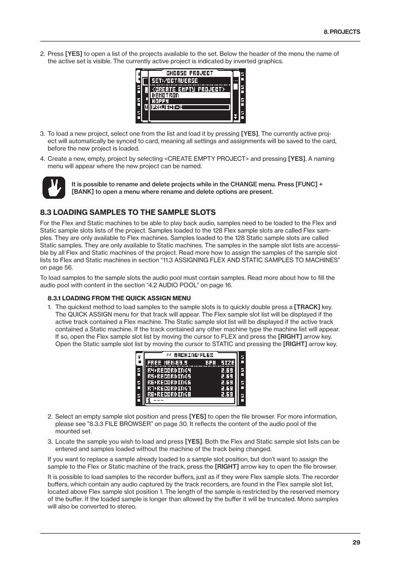
8. PROJECTS
29
2. Press [YES] to open a list of the projects available to the set. Below the header of the menu the name of the active set is visible. The currently active project is indicated by inverted graphics.
3. To load a new project, select one from the list and load it by pressing [YES]. The currently active proj-ect will automatically be synced to card, meaning all settings and assignments will be saved to the card, before the new project is loaded.
4. Create a new, empty, project by selecting <CREATE EMPTY PROJECT> and pressing [YES]. A naming menu will appear where the new project can be named.
It is possible to rename and delete projects while in the CHANGE menu. Press [FUNC] + [BANK] to open a menu where rename and delete options are present.
8.3 LOADING SAMPLES TO THE SAMPLE SLOTSFor the Flex and Static machines to be able to play back audio, samples need to be loaded to the Flex and Static sample slots lists of the project. Samples loaded to the 128 Flex sample slots are called Flex sam-ples. They are only available to Flex machines. Samples loaded to the 128 Static sample slots are called Static samples. They are only available to Static machines. The samples in the sample slot lists are accessi-ble by all Flex and Static machines of the project. Read more how to assign the samples of the sample slot lists to Flex and Static machines in section “11.3 ASSIGNING FLEX AND STATIC SAMPLES TO MACHINES” on page 56.
To load samples to the sample slots the audio pool must contain samples. Read more about how to fill the audio pool with content in the section “4.2 AUDIO POOL” on page 16.
8.3.1 LOADING FROM THE QUICK ASSIGN MENU1. The quickest method to load samples to the sample slots is to quickly double press a [TRACK] key.
The QUICK ASSIGN menu for that track will appear. The Flex sample slot list will be displayed if the active track contained a Flex machine. The Static sample slot list will be displayed if the active track contained a Static machine. If the track contained any other machine type the machine list will appear. If so, open the Flex sample slot list by moving the cursor to FLEX and press the [RIGHT] arrow key. Open the Static sample slot list by moving the cursor to STATIC and pressing the [RIGHT] arrow key.
2. Select an empty sample slot position and press [YES] to open the file browser. For more information, please see ”8.3.3 FILE BROWSER” on page 30. It reflects the content of the audio pool of the mounted set.
3. Locate the sample you wish to load and press [YES]. Both the Flex and Static sample slot lists can be entered and samples loaded without the machine of the track being changed.
If you want to replace a sample already loaded to a sample slot position, but don’t want to assign the sample to the Flex or Static machine of the track, press the [RIGHT] arrow key to open the file browser.
It is possible to load samples to the recorder buffers, just as if they were Flex sample slots. The recorder buffers, which contain any audio captured by the track recorders, are found in the Flex sample slot list, located above Flex sample slot position 1. The length of the sample is restricted by the reserved memory of the buffer. If the loaded sample is longer than allowed by the buffer it will be truncated. Mono samples will also be converted to stereo.
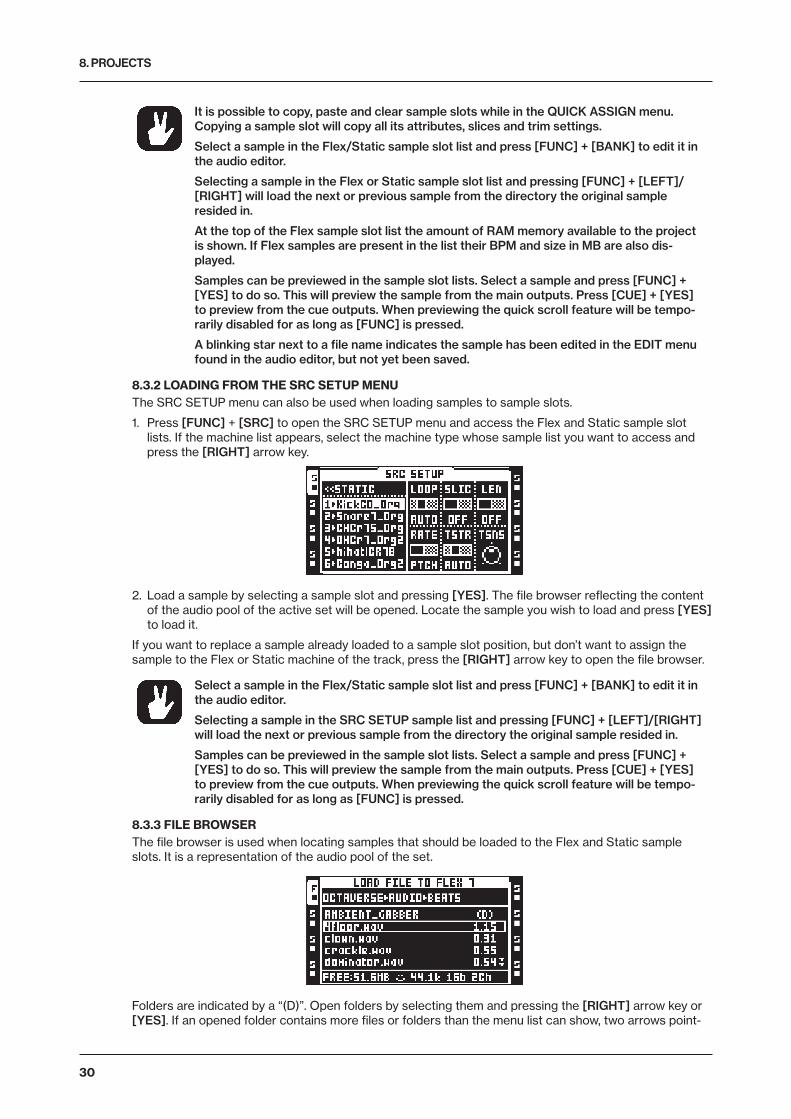
8. PROJECTS
30
It is possible to copy, paste and clear sample slots while in the QUICK ASSIGN menu. Copying a sample slot will copy all its attributes, slices and trim settings.
Select a sample in the Flex/Static sample slot list and press [FUNC] + [BANK] to edit it in the audio editor.
Selecting a sample in the Flex or Static sample slot list and pressing [FUNC] + [LEFT]/[RIGHT] will load the next or previous sample from the directory the original sample resided in.
At the top of the Flex sample slot list the amount of RAM memory available to the project is shown. If Flex samples are present in the list their BPM and size in MB are also dis-played.
Samples can be previewed in the sample slot lists. Select a sample and press [FUNC] + [YES] to do so. This will preview the sample from the main outputs. Press [CUE] + [YES] to preview from the cue outputs. When previewing the quick scroll feature will be tempo-rarily disabled for as long as [FUNC] is pressed.
A blinking star next to a file name indicates the sample has been edited in the EDIT menu found in the audio editor, but not yet been saved.
8.3.2 LOADING FROM THE SRC SETUP MENUThe SRC SETUP menu can also be used when loading samples to sample slots.
1. Press [FUNC] + [SRC] to open the SRC SETUP menu and access the Flex and Static sample slot lists. If the machine list appears, select the machine type whose sample list you want to access and press the [RIGHT] arrow key.
2. Load a sample by selecting a sample slot and pressing [YES]. The file browser reflecting the content of the audio pool of the active set will be opened. Locate the sample you wish to load and press [YES] to load it.
If you want to replace a sample already loaded to a sample slot position, but don’t want to assign the sample to the Flex or Static machine of the track, press the [RIGHT] arrow key to open the file browser.
Select a sample in the Flex/Static sample slot list and press [FUNC] + [BANK] to edit it in the audio editor.
Selecting a sample in the SRC SETUP sample list and pressing [FUNC] + [LEFT]/[RIGHT] will load the next or previous sample from the directory the original sample resided in.
Samples can be previewed in the sample slot lists. Select a sample and press [FUNC] + [YES] to do so. This will preview the sample from the main outputs. Press [CUE] + [YES] to preview from the cue outputs. When previewing the quick scroll feature will be tempo-rarily disabled for as long as [FUNC] is pressed.
8.3.3 FILE BROWSERThe file browser is used when locating samples that should be loaded to the Flex and Static sample slots. It is a representation of the audio pool of the set.
Folders are indicated by a “(D)”. Open folders by selecting them and pressing the [RIGHT] arrow key or [YES]. If an opened folder contains more files or folders than the menu list can show, two arrows point-
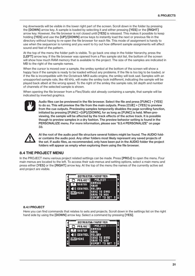
8. PROJECTS
31
ing downwards will be visible in the lower right part of the screen. Scroll down in the folder by pressing the [DOWN] arrow key. A sample is loaded by selecting it and either pressing [YES] or the [RIGHT] arrow key. However, the file browser is not closed until [YES] is released. This makes it possible to keep holding [YES] and use the [UP]/[DOWN] arrow keys to instantly load the next or previous file in the directory without having to re-open the file browser for each file. This mode of assignment is handy to use when the sequencer is running and you want to try out how different sample assignments will affect sound and feel of the pattern.
At the top of the menu the folder path is visible. To go back one step in the folder hierarchy, press the [LEFT] arrow key. If the file browser was opened from a Flex sample slot list, the bottom of the screen will show how much RAM memory that is available to the project. The size of the samples are indicated in MB to the right of the sample names.
When the cursor is moved over a sample, the smiley symbol at the bottom of the screen will show a happy face if the sample is ready to be loaded without any problems. If the file is too big to be loaded, or if the file is incompatible with the Octatrack MKII audio engine, the smiley will look sad. Samples with an unsupported sample rate, like 48 kHz, will make the smiley look indifferent, indicating the sample will be played back albeit at the wrong speed. To the right of the smiley the sample rate, bit depth and number of channels of the selected sample is shown.
When opening the file browser from a Flex/Static slot already containing a sample, that sample will be indicated by inverted graphics.
Audio files can be previewed in the file browser. Select the file and press [FUNC] + [YES] to do so. This will preview the file from the main outputs. Press [CUE] + [YES] to preview from the cue outputs. Previewing samples temporarily disables the page scrolling function, initiated by pressing [FUNC] +[UP]/[DOWN], for as long as [FUNC] is held. When pre-viewing, the sample will be affected by the track effects of the active track. It is possible though to preview samples in a dry fashion. The preview behavior setting is found in the PERSONALIZE menu. For more information, please see “8.5.4 PERSONALIZE” on page 33.
At the root of the audio pool file structure several folders might be found. The AUDIO fold-er contains the audio pool. Any other folders most likely represent any saved projects of the set. If audio files, as recommended, only have been put in the AUDIO folder the project folders will appear as empty when exploring them using the file browser.
8.4 THE PROJECT MENUIn the PROJECT menu various project related settings can be made. Press [PROJ] to open the menu. Four main menus are located to the left. To access their sub-menus and setting options, select a main menu and press either [YES] or the [RIGHT] arrow key. At the top of the menu the names of the currently active set and project are visible.
8.4.1 PROJECTHere you can find commands that relates to sets and projects. Scroll down in the settings list on the right hand side by using the [DOWN] arrow key. Select a command by pressing [YES].
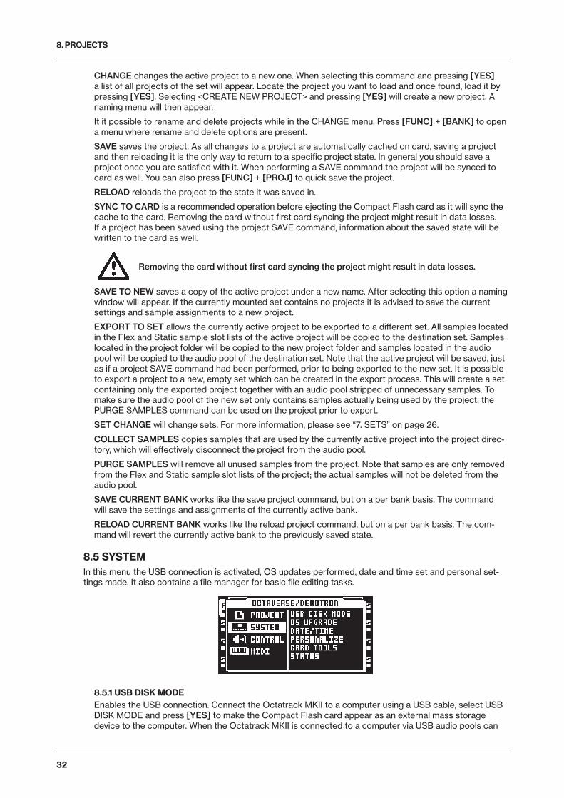
8. PROJECTS
32
CHANGE changes the active project to a new one. When selecting this command and pressing [YES] a list of all projects of the set will appear. Locate the project you want to load and once found, load it by pressing [YES]. Selecting <CREATE NEW PROJECT> and pressing [YES] will create a new project. A naming menu will then appear.
It it possible to rename and delete projects while in the CHANGE menu. Press [FUNC] + [BANK] to open a menu where rename and delete options are present.
SAVE saves the project. As all changes to a project are automatically cached on card, saving a project and then reloading it is the only way to return to a specific project state. In general you should save a project once you are satisfied with it. When performing a SAVE command the project will be synced to card as well. You can also press [FUNC] + [PROJ] to quick save the project.
RELOAD reloads the project to the state it was saved in.
SYNC TO CARD is a recommended operation before ejecting the Compact Flash card as it will sync the cache to the card. Removing the card without first card syncing the project might result in data losses. If a project has been saved using the project SAVE command, information about the saved state will be written to the card as well.
Removing the card without first card syncing the project might result in data losses.
SAVE TO NEW saves a copy of the active project under a new name. After selecting this option a naming window will appear. If the currently mounted set contains no projects it is advised to save the current settings and sample assignments to a new project.
EXPORT TO SET allows the currently active project to be exported to a different set. All samples located in the Flex and Static sample slot lists of the active project will be copied to the destination set. Samples located in the project folder will be copied to the new project folder and samples located in the audio pool will be copied to the audio pool of the destination set. Note that the active project will be saved, just as if a project SAVE command had been performed, prior to being exported to the new set. It is possible to export a project to a new, empty set which can be created in the export process. This will create a set containing only the exported project together with an audio pool stripped of unnecessary samples. To make sure the audio pool of the new set only contains samples actually being used by the project, the PURGE SAMPLES command can be used on the project prior to export.
SET CHANGE will change sets. For more information, please see “7. SETS” on page 26.
COLLECT SAMPLES copies samples that are used by the currently active project into the project direc-tory, which will effectively disconnect the project from the audio pool.
PURGE SAMPLES will remove all unused samples from the project. Note that samples are only removed from the Flex and Static sample slot lists of the project; the actual samples will not be deleted from the audio pool.
SAVE CURRENT BANK works like the save project command, but on a per bank basis. The command will save the settings and assignments of the currently active bank.
RELOAD CURRENT BANK works like the reload project command, but on a per bank basis. The com-mand will revert the currently active bank to the previously saved state.
8.5 SYSTEMIn this menu the USB connection is activated, OS updates performed, date and time set and personal set-tings made. It also contains a file manager for basic file editing tasks.
8.5.1 USB DISK MODE Enables the USB connection. Connect the Octatrack MKII to a computer using a USB cable, select USB DISK MODE and press [YES] to make the Compact Flash card appear as an external mass storage device to the computer. When the Octatrack MKII is connected to a computer via USB audio pools can
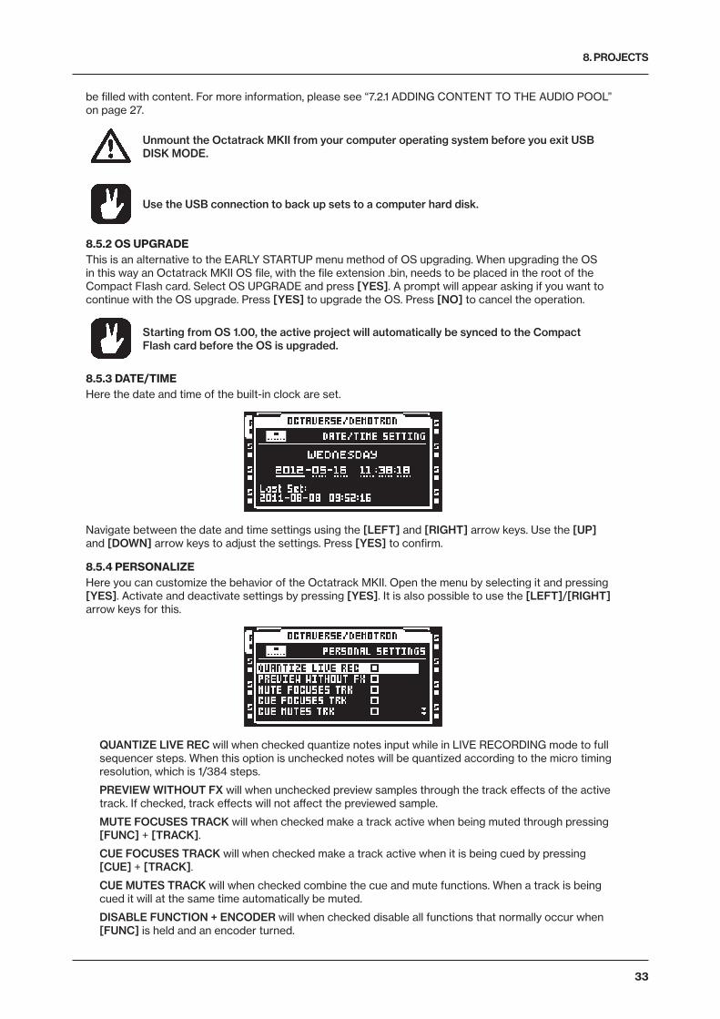
8. PROJECTS
33
be filled with content. For more information, please see “7.2.1 ADDING CONTENT TO THE AUDIO POOL” on page 27.
Unmount the Octatrack MKII from your computer operating system before you exit USB DISK MODE.
Use the USB connection to back up sets to a computer hard disk.
8.5.2 OS UPGRADEThis is an alternative to the EARLY STARTUP menu method of OS upgrading. When upgrading the OS in this way an Octatrack MKII OS file, with the file extension .bin, needs to be placed in the root of the Compact Flash card. Select OS UPGRADE and press [YES]. A prompt will appear asking if you want to continue with the OS upgrade. Press [YES] to upgrade the OS. Press [NO] to cancel the operation.
Starting from OS 1.00, the active project will automatically be synced to the Compact Flash card before the OS is upgraded.
8.5.3 DATE/TIME Here the date and time of the built-in clock are set.
Navigate between the date and time settings using the [LEFT] and [RIGHT] arrow keys. Use the [UP] and [DOWN] arrow keys to adjust the settings. Press [YES] to confirm.
8.5.4 PERSONALIZEHere you can customize the behavior of the Octatrack MKII. Open the menu by selecting it and pressing [YES]. Activate and deactivate settings by pressing [YES]. It is also possible to use the [LEFT]/[RIGHT] arrow keys for this.
QUANTIZE LIVE REC will when checked quantize notes input while in LIVE RECORDING mode to full sequencer steps. When this option is unchecked notes will be quantized according to the micro timing resolution, which is 1/384 steps.
PREVIEW WITHOUT FX will when unchecked preview samples through the track effects of the active track. If checked, track effects will not affect the previewed sample.
MUTE FOCUSES TRACK will when checked make a track active when being muted through pressing [FUNC] + [TRACK].
CUE FOCUSES TRACK will when checked make a track active when it is being cued by pressing [CUE] + [TRACK].
CUE MUTES TRACK will when checked combine the cue and mute functions. When a track is being cued it will at the same time automatically be muted.
DISABLE FUNCTION + ENCODER will when checked disable all functions that normally occur when [FUNC] is held and an encoder turned.
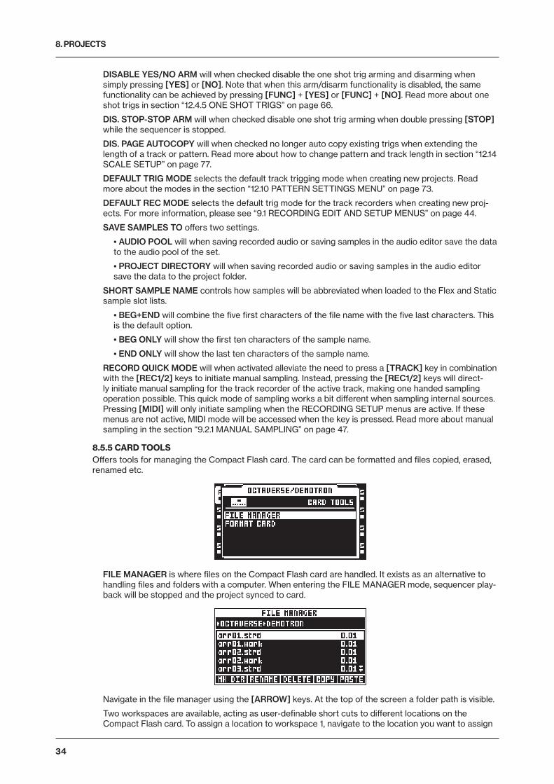
8. PROJECTS
34
DISABLE YES/NO ARM will when checked disable the one shot trig arming and disarming when simply pressing [YES] or [NO]. Note that when this arm/disarm functionality is disabled, the same functionality can be achieved by pressing [FUNC] + [YES] or [FUNC] + [NO]. Read more about one shot trigs in section “12.4.5 ONE SHOT TRIGS” on page 66.
DIS. STOP-STOP ARM will when checked disable one shot trig arming when double pressing [STOP] while the sequencer is stopped.
DIS. PAGE AUTOCOPY will when checked no longer auto copy existing trigs when extending the length of a track or pattern. Read more about how to change pattern and track length in section “12.14 SCALE SETUP” on page 77.
DEFAULT TRIG MODE selects the default track trigging mode when creating new projects. Read more about the modes in the section “12.10 PATTERN SETTINGS MENU” on page 73.
DEFAULT REC MODE selects the default trig mode for the track recorders when creating new proj-ects. For more information, please see “9.1 RECORDING EDIT AND SETUP MENUS” on page 44.
SAVE SAMPLES TO offers two settings.
• AUDIO POOL will when saving recorded audio or saving samples in the audio editor save the data to the audio pool of the set.
• PROJECT DIRECTORY will when saving recorded audio or saving samples in the audio editor save the data to the project folder.
SHORT SAMPLE NAME controls how samples will be abbreviated when loaded to the Flex and Static sample slot lists.
• BEG+END will combine the five first characters of the file name with the five last characters. This is the default option.
• BEG ONLY will show the first ten characters of the sample name.
• END ONLY will show the last ten characters of the sample name.
RECORD QUICK MODE will when activated alleviate the need to press a [TRACK] key in combination with the [REC1/2] keys to initiate manual sampling. Instead, pressing the [REC1/2] keys will direct-ly initiate manual sampling for the track recorder of the active track, making one handed sampling operation possible. This quick mode of sampling works a bit different when sampling internal sources. Pressing [MIDI] will only initiate sampling when the RECORDING SETUP menus are active. If these menus are not active, MIDI mode will be accessed when the key is pressed. Read more about manual sampling in the section “9.2.1 MANUAL SAMPLING” on page 47.
8.5.5 CARD TOOLSOffers tools for managing the Compact Flash card. The card can be formatted and files copied, erased, renamed etc.
FILE MANAGER is where files on the Compact Flash card are handled. It exists as an alternative to handling files and folders with a computer. When entering the FILE MANAGER mode, sequencer play-back will be stopped and the project synced to card.
Navigate in the file manager using the [ARROW] keys. At the top of the screen a folder path is visible.
Two workspaces are available, acting as user-definable short cuts to different locations on the Compact Flash card. To assign a location to workspace 1, navigate to the location you want to assign
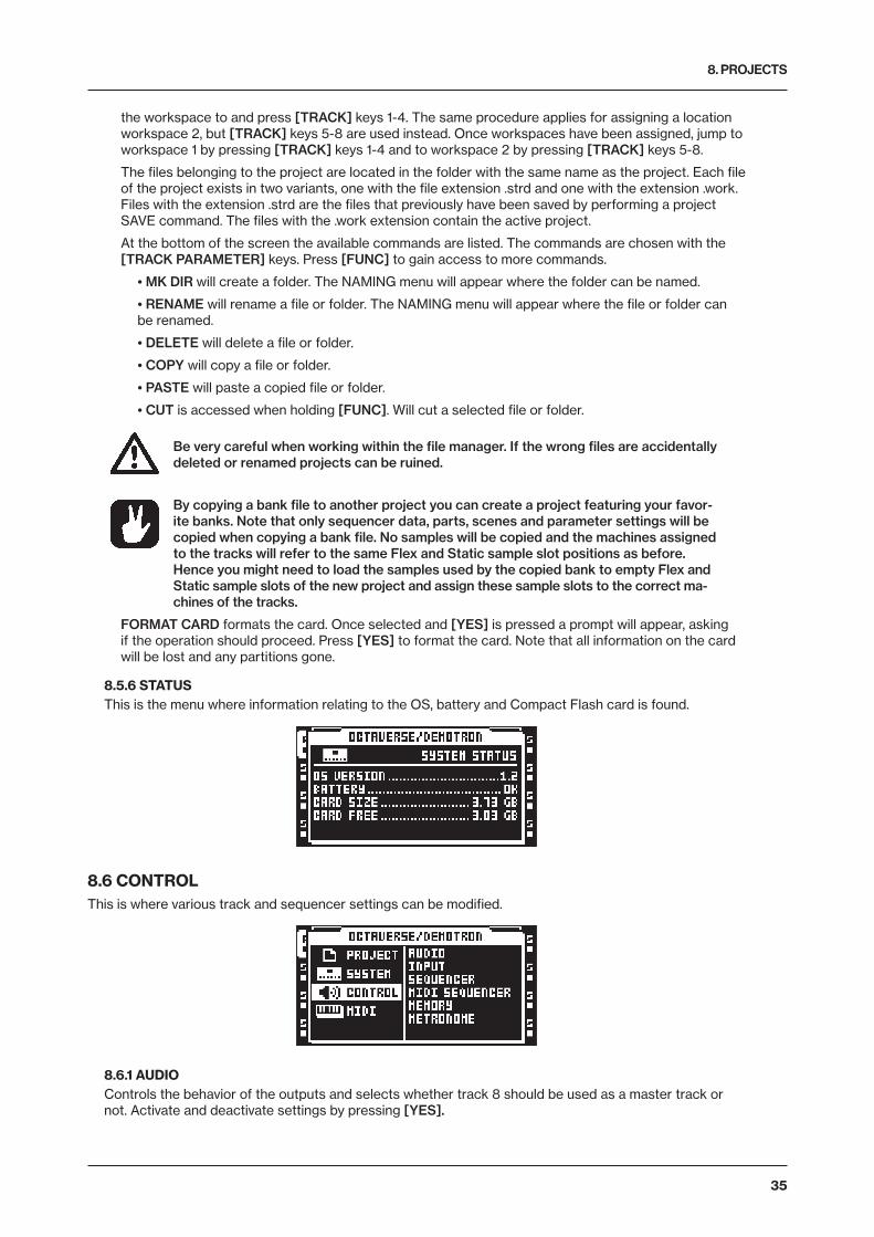
8. PROJECTS
35
the workspace to and press [TRACK] keys 1-4. The same procedure applies for assigning a location workspace 2, but [TRACK] keys 5-8 are used instead. Once workspaces have been assigned, jump to workspace 1 by pressing [TRACK] keys 1-4 and to workspace 2 by pressing [TRACK] keys 5-8.
The files belonging to the project are located in the folder with the same name as the project. Each file of the project exists in two variants, one with the file extension .strd and one with the extension .work. Files with the extension .strd are the files that previously have been saved by performing a project SAVE command. The files with the .work extension contain the active project.
At the bottom of the screen the available commands are listed. The commands are chosen with the [TRACK PARAMETER] keys. Press [FUNC] to gain access to more commands.
• MK DIR will create a folder. The NAMING menu will appear where the folder can be named.
• RENAME will rename a file or folder. The NAMING menu will appear where the file or folder can be renamed.
• DELETE will delete a file or folder.
• COPY will copy a file or folder.
• PASTE will paste a copied file or folder.
• CUT is accessed when holding [FUNC]. Will cut a selected file or folder.
Be very careful when working within the file manager. If the wrong files are accidentally deleted or renamed projects can be ruined.
By copying a bank file to another project you can create a project featuring your favor-ite banks. Note that only sequencer data, parts, scenes and parameter settings will be copied when copying a bank file. No samples will be copied and the machines assigned to the tracks will refer to the same Flex and Static sample slot positions as before. Hence you might need to load the samples used by the copied bank to empty Flex and Static sample slots of the new project and assign these sample slots to the correct ma-chines of the tracks.
FORMAT CARD formats the card. Once selected and [YES] is pressed a prompt will appear, asking if the operation should proceed. Press [YES] to format the card. Note that all information on the card will be lost and any partitions gone.
8.5.6 STATUS This is the menu where information relating to the OS, battery and Compact Flash card is found.
8.6 CONTROLThis is where various track and sequencer settings can be modified.
8.6.1 AUDIO Controls the behavior of the outputs and selects whether track 8 should be used as a master track or not. Activate and deactivate settings by pressing [YES].

8. PROJECTS
36
TRACK 8 offers two settings. Only one setting can be activated at a time.
• MASTER will when active turn track 8 into a master track. The track effects of track 8 will then affect all the other tracks as well as any audio coming from the external inputs.
• NORMAL will make track 8 function like all the other tracks.
AMP SETUP, LFO MAIN/SETUP and FX1 and FX2 MAIN/SETUP are the only TRACK PARAMETER pages available to a master track.
CUE CFG offers settings which can make the cue outputs function as an assignable pair of outputs. Two settings are available. Only one setting can be activated at a time. Read more about the cue out-puts in section “11.6 MAIN AND CUE OUTPUTS ROUTING” on page 62.
• NORMAL will make the cue outputs function normally, meaning a track will be routed to the cue outputs when [CUE] + [TRACK] is pressed.
• STUDIO will disable the normal cue functionality. Audio tracks can now be routed to the cue out-puts as if they were a standard pair of assignable outputs. Each audio track gets two independent LEV settings, one for the main outs and one for the cue outs. Adjust the LEV setting for the main outputs by turning the LEVEL knob. Adjust the LEV setting for the cue outputs by pressing [CUE] and turning the LEVEL knob. Muting a track while STUDIO mode is enabled will mute the sound from both the main and cue outputs.
8.6.2 INPUTControls the noise gates and the delay compensation of the audio inputs.
NOISE GATE AB sets the dB level of the noise gate for input pair AB. The threshold is set with the LEVEL knob. Any signal below the threshold will be cut. An -INF setting deactivates the noise gate.
NOISE GATE CD sets the dB level of the noise gate for input pair CD. The threshold is set with the LEVEL knob. Any signal below the threshold will be cut. An -INF setting deactivates the noise gate.
DELAY COMPENSATE will when activated introduce a very short delay to the audio signal listened to via the DIR setting. If for example an audio signal is listened to through both the DIR input and a Thru machine/Pickup machine, both signals will then be in sync. If DELAY COMPENSATE would have been deactivated in the above scenario, the delay caused by the internal processing would make the audio signal routed to the Thru/Pickup machine play a few milliseconds later than the DIR signal. The com-bined DIR and Thru/Pickup signal would then exhibit a slightly phased sound.
8.6.3 SEQUENCERHere the default behavior of the sequencer is set.
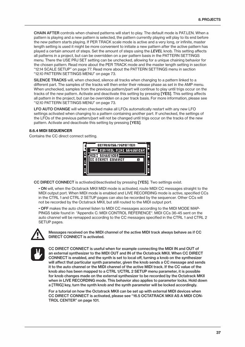
8. PROJECTS
37
CHAIN AFTER controls when chained patterns will start to play. The default mode is PAT.LEN. When a pattern is playing and a new pattern is selected, the pattern currently playing will play to its end before the new pattern starts playing. If PER TRACK scale mode is active and a very long, or infinite, master length setting is used it might be more convenient to initiate a new pattern after the active pattern has played a certain amount of steps. Set the amount of steps using the LEVEL knob. This setting affects all patterns in a project, but can be overridden on a per pattern basis in the PATTERN SETTINGS menu. There the USE PRJ SET setting can be unchecked, allowing for a unique chaining behavior for the chosen pattern. Read more about the PER TRACK mode and the master length setting in section “12.14 SCALE SETUP” on page 77. Read more about the PATTERN SETTINGS menu in section “12.10 PATTERN SETTINGS MENU” on page 73.
SILENCE TRACKS will, when checked, silence all tracks when changing to a pattern linked to a different part. The samples of the tracks will then enter their release phase as set in the AMP menu. When unchecked, samples from the previous pattern/part will continue to play until trigs occur on the tracks of the new pattern. Activate and deactivate this setting by pressing [YES]. This setting affects all pattern in the project, but can be overridden on a per track basis. For more information, please see “12.10 PATTERN SETTINGS MENU” on page 73.
LFO AUTO CHANGE will when checked make all LFOs automatically restart with any new LFO settings activated when changing to a pattern containing another part. If unchecked, the settings of the LFOs of the previous pattern/part will not be changed until trigs occur on the tracks of the new pattern. Activate and deactivate this setting by pressing [YES].
8.6.4 MIDI SEQUENCER Contains the CC direct connect setting.
CC DIRECT CONNECT is activated/deactivated by pressing [YES]. Two settings exist.
• ON will, when the Octatrack MKII MIDI mode is activated, route MIDI CC messages straight to the MIDI output port. When MIDI mode is enabled and LIVE RECORDING mode is active, specified CCs in the CTRL 1 and CTRL 2 SETUP pages can also be recorded by the sequencer. Other CCs will not be recorded by the Octatrack MKII, but still routed to the MIDI output port.
• OFF makes the auto channel listen to MIDI CC messages according to the MIDI MODE MAP-PINGS table found in “Appendix C: MIDI CONTROL REFERENCE“. MIDI CCs 36-45 sent on the auto channel will be remapped according to the CC messages specified in the CTRL 1 and CTRL 2 SETUP pages.
Messages received on the MIDI channel of the active MIDI track always behave as if CC DIRECT CONNECT is activated.
CC DIRECT CONNECT is useful when for example connecting the MIDI IN and OUT of an external synthesizer to the MIDI OUT and IN of the Octatrack MKII. When CC DIRECT CONNECT is enabled, and the synth is set to local off, turning a knob on the synthesizer will affect that particular synth parameter, given the knob sends a CC message and sends it to the auto channel or the MIDI channel of the active MIDI track. If the CC value of the knob also has been mapped to a CTRL 1/CTRL 2 SETUP menu parameter, it is possible for knob changes made on the external synthesizer to be recorded by the Octatrack MKII when in LIVE RECORDING mode. This behavior also applies to parameter locks. Hold down a [TRIG] key, turn the synth knob and the synth parameter will be locked accordingly.
For a tutorial on how the Octatrack MKII can be set up with external MIDI devices when CC DIRECT CONNECT is activated, please see “16.5 OCTATRACK MKII AS A MIDI CON-TROL CENTER” on page 101.
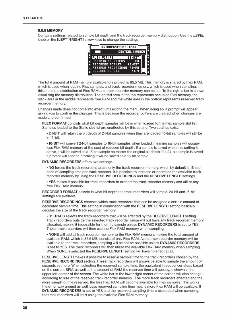
8. PROJECTS
38
8.6.5 MEMORYContains settings related to sample bit depth and the track recorder memory distribution. Use the LEVEL knob or the [LEFT]/[RIGHT] arrow keys to change the settings.
The total amount of RAM memory available to a project is 85,5 MB. This memory is shared by Flex RAM, which is used when loading Flex samples, and track recorder memory, which is used when sampling. In this menu the distribution of Flex RAM and track recorder memory can be set. To the right a bar is shown visualizing the memory distribution. The dotted area in the top represents occupied Flex memory, the black area in the middle represents free RAM and the white area in the bottom represents reserved track recorder memory.
Changes made does not come into effect until exiting the menu. When doing so, a prompt will appear asking you to confirm the changes. This is because the recorder buffers are cleared when changes are made and confirmed.
FLEX FORMAT controls what bit depth samples will be in when loaded to the Flex sample slot list. Samples loaded to the Static slot list are unaffected by this setting. Two settings exist.
• 24-BIT will retain the bit depth of 24-bit samples when they are loaded. 16-bit samples will still be in 16-bit.
• 16-BIT will convert 24-bit samples to 16-bit samples when loaded, meaning samples will occupy less Flex RAM memory at the cost of reduced bit depth. If a sample is saved when this setting is active, it will be saved as a 16 bit sample no matter the original bit depth. If a 24-bit sample is saved a prompt will appear informing it will be saved as a 16-bit sample.
DYNAMIC RECORDERS offers two settings.
• NO forces the track recorders to use only the track recorder memory, which by default is 16 sec-onds of sampling time per track recorder. It is possible to increase or decrease the available track recorder memory by using the RESERVE RECORDINGS and the RESERVE LENGTH settings.
• YES makes it possible for track recorders to exceed the track recorder memory and utilize any free Flex RAM memory.
RECORDER FORMAT selects in what bit depth the track recorders will sample. 24-bit and 16-bit settings are available.
RESERVE RECORDINGS chooses which track recorders that can be assigned a certain amount of dedicated sample time. This setting in combination with the RESERVE LENGTH setting basically decides the size of the track recorder memory.
• R1...R1-R8 selects the track recorders that will be affected by the RESERVE LENGTH setting. Track recorders outside the selected track recorder range will not have any track recorder memory allocated, making it impossible for them to sample unless DYNAMIC RECORDERS is set to YES. These track recorders will then use the Flex RAM memory when sampling.
• NONE will add all track recorder memory to the Flex RAM memory, making the total amount of available RAM, which is 85.5 MB, consist of only Flex RAM. As no track recorder memory will be available to the track recorders, sampling will be not be possible unless DYNAMIC RECORDERS is set to YES. The track recorders will then utilize the available Flex RAM memory when sampling. When NONE is selected the RESERVE LENGTH setting will have no effect at all.
RESERVE LENGTH makes it possible to reserve sample time to the track recorders chosen by the RESERVE RECORDINGS setting. These track recorders will always be able to sample the amount of seconds set here. When selecting the reserved sample time, the equivalent in sequencer steps based on the current BPM, as well as the amount of RAM the reserved time will occupy, is shown in the upper left corner of the screen. The white bar in the lower right corner of the screen will also change according to size of the reserved track recorder memory . The more track recorders affected and the more sampling time reserved, the less Flex RAM will become available for Flex samples. This works the other way around as well. Less reserved sampling time means more Flex RAM will be available. If DYNAMIC RECORDERS is set to YES and the reserved sampling time is exceeded when sampling, the track recorders will start using the available Flex RAM memory.
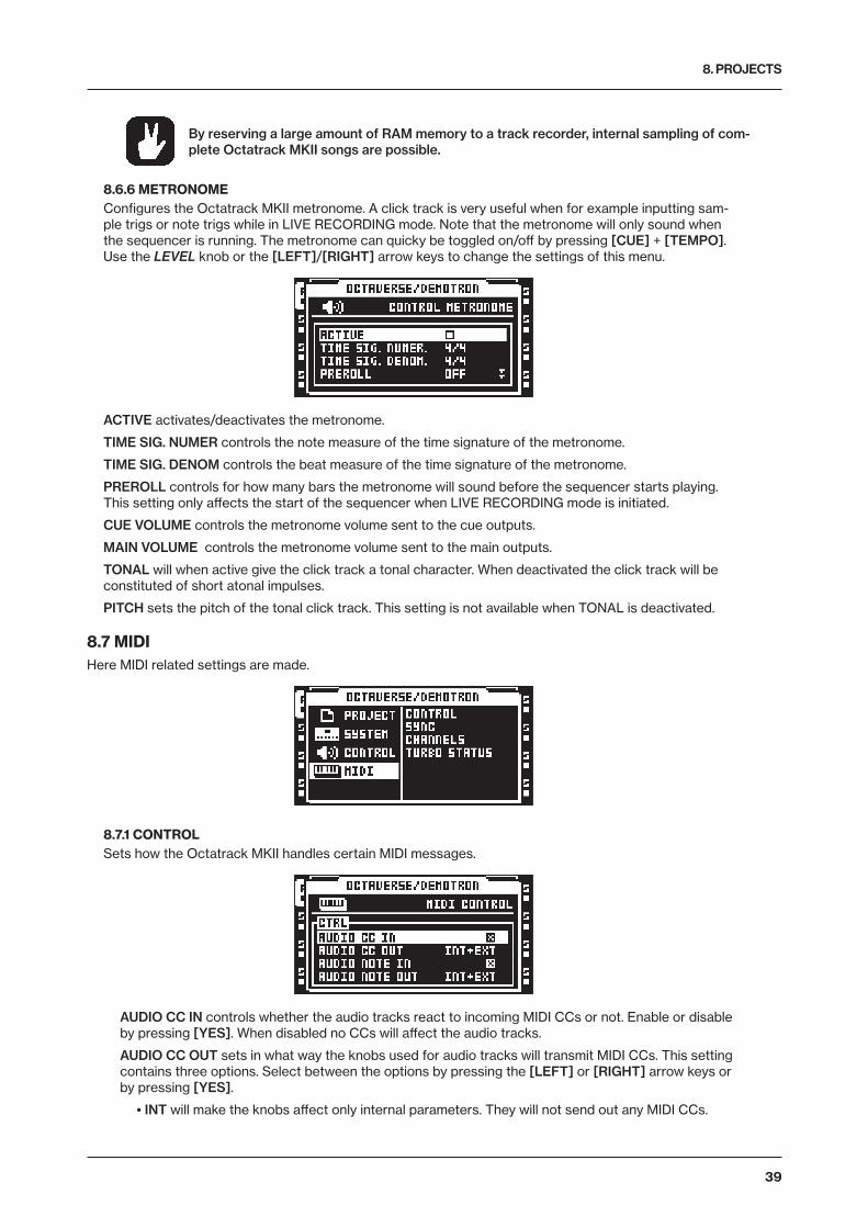
8. PROJECTS
39
By reserving a large amount of RAM memory to a track recorder, internal sampling of com-plete Octatrack MKII songs are possible.
8.6.6 METRONOMEConfigures the Octatrack MKII metronome. A click track is very useful when for example inputting sam-ple trigs or note trigs while in LIVE RECORDING mode. Note that the metronome will only sound when the sequencer is running. The metronome can quicky be toggled on/off by pressing [CUE] + [TEMPO]. Use the LEVEL knob or the [LEFT]/[RIGHT] arrow keys to change the settings of this menu.
ACTIVE activates/deactivates the metronome.
TIME SIG. NUMER controls the note measure of the time signature of the metronome.
TIME SIG. DENOM controls the beat measure of the time signature of the metronome.
PREROLL controls for how many bars the metronome will sound before the sequencer starts playing. This setting only affects the start of the sequencer when LIVE RECORDING mode is initiated.
CUE VOLUME controls the metronome volume sent to the cue outputs.
MAIN VOLUME controls the metronome volume sent to the main outputs.
TONAL will when active give the click track a tonal character. When deactivated the click track will be constituted of short atonal impulses.
PITCH sets the pitch of the tonal click track. This setting is not available when TONAL is deactivated.
8.7 MIDIHere MIDI related settings are made.
8.7.1 CONTROLSets how the Octatrack MKII handles certain MIDI messages.
AUDIO CC IN controls whether the audio tracks react to incoming MIDI CCs or not. Enable or disable by pressing [YES]. When disabled no CCs will affect the audio tracks.
AUDIO CC OUT sets in what way the knobs used for audio tracks will transmit MIDI CCs. This setting contains three options. Select between the options by pressing the [LEFT] or [RIGHT] arrow keys or by pressing [YES].
• INT will make the knobs affect only internal parameters. They will not send out any MIDI CCs.
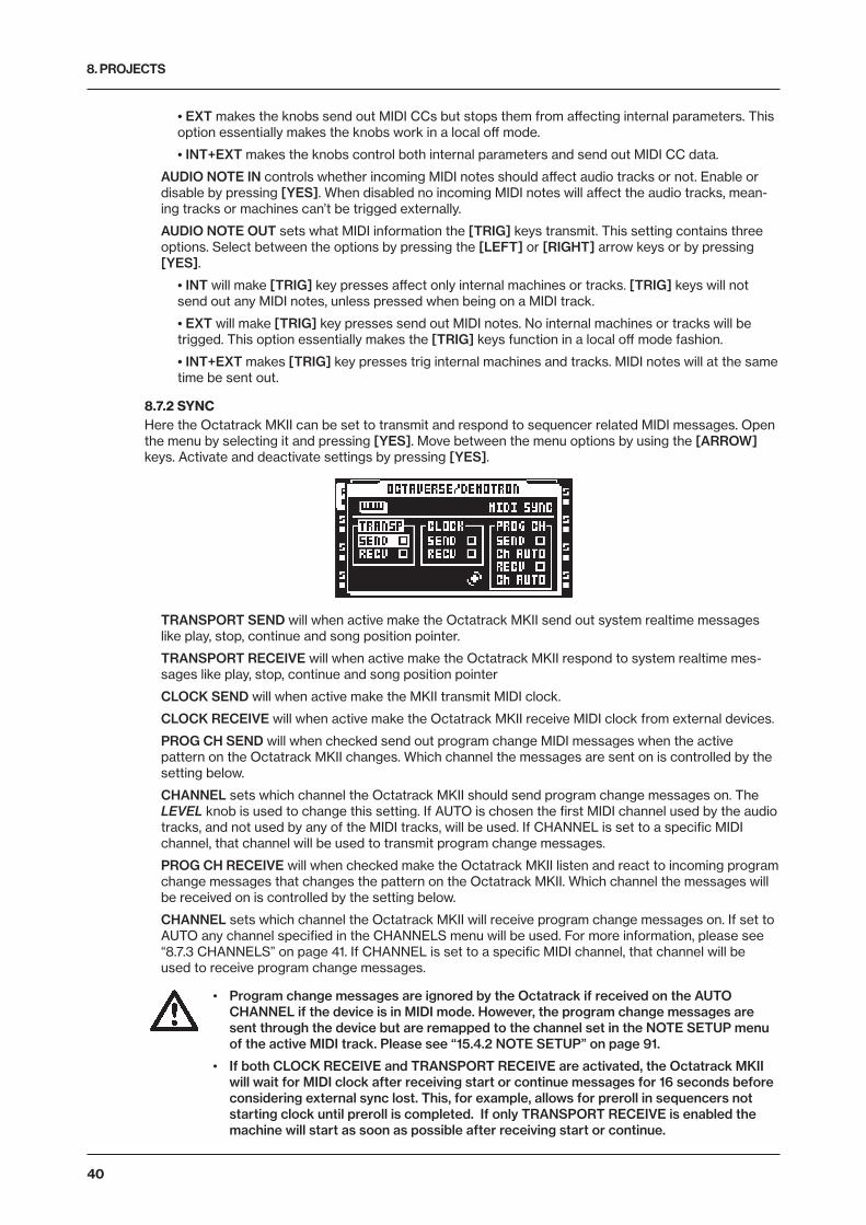
8. PROJECTS
40
• EXT makes the knobs send out MIDI CCs but stops them from affecting internal parameters. This option essentially makes the knobs work in a local off mode.
• INT+EXT makes the knobs control both internal parameters and send out MIDI CC data.
AUDIO NOTE IN controls whether incoming MIDI notes should affect audio tracks or not. Enable or disable by pressing [YES]. When disabled no incoming MIDI notes will affect the audio tracks, mean-ing tracks or machines can’t be trigged externally.
AUDIO NOTE OUT sets what MIDI information the [TRIG] keys transmit. This setting contains three options. Select between the options by pressing the [LEFT] or [RIGHT] arrow keys or by pressing [YES].
• INT will make [TRIG] key presses affect only internal machines or tracks. [TRIG] keys will not send out any MIDI notes, unless pressed when being on a MIDI track.
• EXT will make [TRIG] key presses send out MIDI notes. No internal machines or tracks will be trigged. This option essentially makes the [TRIG] keys function in a local off mode fashion.
• INT+EXT makes [TRIG] key presses trig internal machines and tracks. MIDI notes will at the same time be sent out.
8.7.2 SYNCHere the Octatrack MKII can be set to transmit and respond to sequencer related MIDI messages. Open the menu by selecting it and pressing [YES]. Move between the menu options by using the [ARROW] keys. Activate and deactivate settings by pressing [YES].
TRANSPORT SEND will when active make the Octatrack MKII send out system realtime messages like play, stop, continue and song position pointer.
TRANSPORT RECEIVE will when active make the Octatrack MKII respond to system realtime mes-sages like play, stop, continue and song position pointer
CLOCK SEND will when active make the MKII transmit MIDI clock.
CLOCK RECEIVE will when active make the Octatrack MKII receive MIDI clock from external devices.
PROG CH SEND will when checked send out program change MIDI messages when the active pattern on the Octatrack MKII changes. Which channel the messages are sent on is controlled by the setting below.
CHANNEL sets which channel the Octatrack MKII should send program change messages on. The LEVEL knob is used to change this setting. If AUTO is chosen the first MIDI channel used by the audio tracks, and not used by any of the MIDI tracks, will be used. If CHANNEL is set to a specific MIDI channel, that channel will be used to transmit program change messages.
PROG CH RECEIVE will when checked make the Octatrack MKII listen and react to incoming program change messages that changes the pattern on the Octatrack MKII. Which channel the messages will be received on is controlled by the setting below.
CHANNEL sets which channel the Octatrack MKII will receive program change messages on. If set to AUTO any channel specified in the CHANNELS menu will be used. For more information, please see “8.7.3 CHANNELS” on page 41. If CHANNEL is set to a specific MIDI channel, that channel will be used to receive program change messages.
• Program change messages are ignored by the Octatrack if received on the AUTO CHANNEL if the device is in MIDI mode. However, the program change messages are sent through the device but are remapped to the channel set in the NOTE SETUP menu of the active MIDI track. Please see “15.4.2 NOTE SETUP” on page 91.
• If both CLOCK RECEIVE and TRANSPORT RECEIVE are activated, the Octatrack MKII will wait for MIDI clock after receiving start or continue messages for 16 seconds before considering external sync lost. This, for example, allows for preroll in sequencers not starting clock until preroll is completed. If only TRANSPORT RECEIVE is enabled the machine will start as soon as possible after receiving start or continue.

8. PROJECTS
41
8.7.3 CHANNELSThis where the MIDI channel configuration of the audio tracks is done. Navigate in the menu with the [LEFT] and [RIGHT] arrow keys. Change MIDI channels by using the [UP] and [DOWN] arrow keys or the LEVEL knob.
AUTO CHANNEL is the MIDI channel giving access to the currently active track. MIDI CC messages sent to the auto channel can in LIVE RECORDING mode be recorded to the active track. When in MIDI mode and CC DIRECT CONNECT is enabled, CC messages sent to the auto channel will be sent straight to the MIDI output port. CC messages specified in the CTRL 1 and CTRL 2 SETUP menus can also be recorded while in LIVE RECORDING mode. If CC DIRECT CONNECT is disabled the Octatrack MKII MIDI tracks will react to incoming CCs according to the MIDI MODE MAPPINGS table found in “APPENDIX C: MIDI CONTROL REFERENCE” on page 136.
Pitch information for the audio tracks can be recorded in a chromatic fashion by sending MIDI note data to the auto channel. This is another way of controlling samples chromatically instead of using CHROMATIC mode. For more info about this, please see the NOTE MAPPINGS table found in “AP-PENDIX C: MIDI CONTROL REFERENCE” on page 136. Read about the CHROMATIC mode in section “12.7.2 CHROMATIC” on page 68.
TRIG CHANNEL sets which MIDI channels the audio tracks respond and send data to. If for example MIDI channel 1 is assigned to track 1, the track can be externally controlled according to the mappings found in “APPENDIX C: MIDI CONTROL REFERENCE” on page 136. The track can at the same time, when active, send out MIDI data on MIDI channel 1. This occurs when the DATA ENTRY knobs are adjusted and when [TRIG] keys are pressed. An OFF setting means the audio track will not respond to, nor send out, any MIDI data.
To avoid unwanted MIDI conflicts when controlling external instruments with the Octatrack MKII MIDI sequencer, the MIDI channels assigned to the audio tracks should preferably not be the same as those assigned to the MIDI tracks. Read more about this matter in section “15.2 HOW MIDI IS ROUTED” on page 89.
Parameter locks and scene locks can be entered via the auto channel. This is done by holding down a [TRIG] key or a [SCENE] key and sending the corresponding CC message. MIDI CC mappings are covered in “APPENDIX C: MIDI CONTROL REFERENCE” on page 136.
8.7.4 TURBO STATUSAllows Turbo mode negotiation between Elektron gear. Connecting the Octatrack MKII to other Turbo protocol compatible gear, like the Machinedrum and the Monomachine, makes it possible to increase the normal MIDI bandwidth by up to 10x. This increases the accuracy of MIDI clock signals as well as the timing of CC messages. Note that Octatrack MKII MIDI IN/OUT must be connected to the MIDI OUT/IN of the turbo protocol compatible device for the Turbo mode negotiation to function.
CURRENT SPEED shows the current multiplier of the MIDI transfer rate. When the Octatrack MKII is not connected to a MIDI device using Turbo protocol compatible software, the speed will be x 1.0.
NEGOTIATE selects the multiplier of the MIDI transfer rate that should be used. The [LEFT]/[RIGHT] arrow keys are used. Press [YES] to start the negotiation.
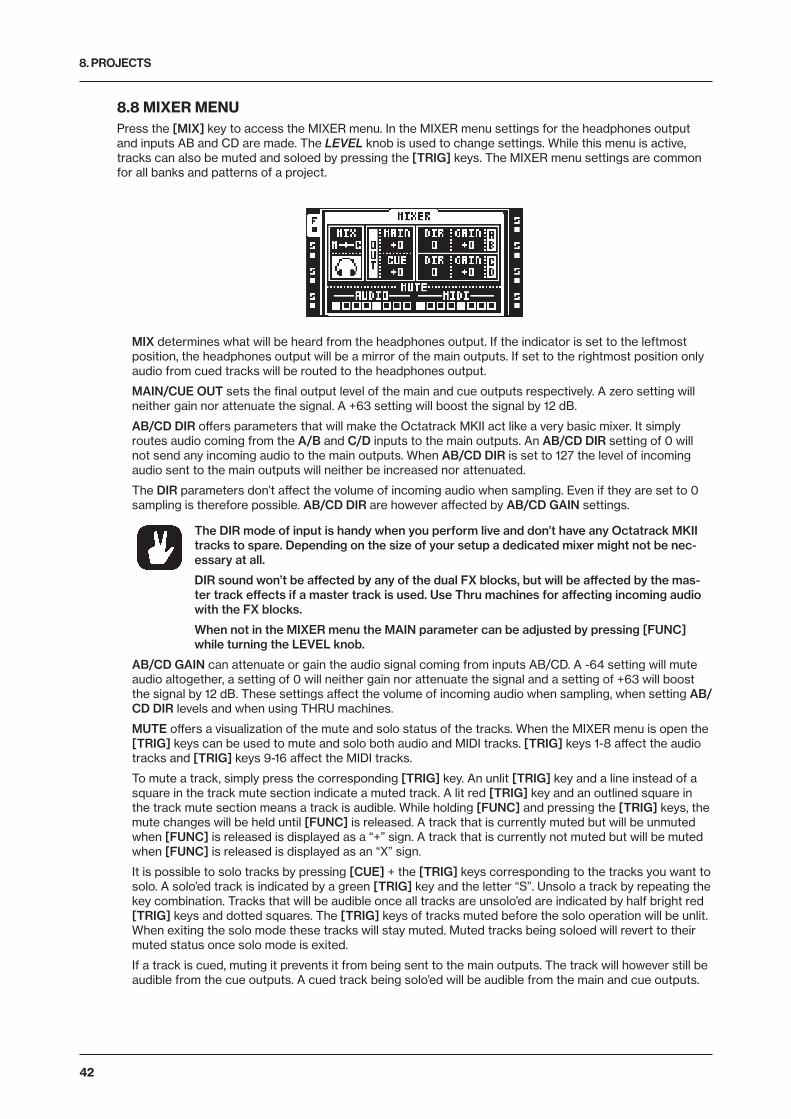
8. PROJECTS
42
8.8 MIXER MENUPress the [MIX] key to access the MIXER menu. In the MIXER menu settings for the headphones output and inputs AB and CD are made. The LEVEL knob is used to change settings. While this menu is active, tracks can also be muted and soloed by pressing the [TRIG] keys. The MIXER menu settings are common for all banks and patterns of a project.
MIX determines what will be heard from the headphones output. If the indicator is set to the leftmost position, the headphones output will be a mirror of the main outputs. If set to the rightmost position only audio from cued tracks will be routed to the headphones output.
MAIN/CUE OUT sets the final output level of the main and cue outputs respectively. A zero setting will neither gain nor attenuate the signal. A +63 setting will boost the signal by 12 dB.
AB/CD DIR offers parameters that will make the Octatrack MKII act like a very basic mixer. It simply routes audio coming from the A/B and C/D inputs to the main outputs. An AB/CD DIR setting of 0 will not send any incoming audio to the main outputs. When AB/CD DIR is set to 127 the level of incoming audio sent to the main outputs will neither be increased nor attenuated.
The DIR parameters don’t affect the volume of incoming audio when sampling. Even if they are set to 0 sampling is therefore possible. AB/CD DIR are however affected by AB/CD GAIN settings.
The DIR mode of input is handy when you perform live and don’t have any Octatrack MKII tracks to spare. Depending on the size of your setup a dedicated mixer might not be nec-essary at all.
DIR sound won’t be affected by any of the dual FX blocks, but will be affected by the mas-ter track effects if a master track is used. Use Thru machines for affecting incoming audio with the FX blocks.
When not in the MIXER menu the MAIN parameter can be adjusted by pressing [FUNC] while turning the LEVEL knob.
AB/CD GAIN can attenuate or gain the audio signal coming from inputs AB/CD. A -64 setting will mute audio altogether, a setting of 0 will neither gain nor attenuate the signal and a setting of +63 will boost the signal by 12 dB. These settings affect the volume of incoming audio when sampling, when setting AB/CD DIR levels and when using THRU machines.
MUTE offers a visualization of the mute and solo status of the tracks. When the MIXER menu is open the [TRIG] keys can be used to mute and solo both audio and MIDI tracks. [TRIG] keys 1-8 affect the audio tracks and [TRIG] keys 9-16 affect the MIDI tracks.
To mute a track, simply press the corresponding [TRIG] key. An unlit [TRIG] key and a line instead of a square in the track mute section indicate a muted track. A lit red [TRIG] key and an outlined square in the track mute section means a track is audible. While holding [FUNC] and pressing the [TRIG] keys, the mute changes will be held until [FUNC] is released. A track that is currently muted but will be unmuted when [FUNC] is released is displayed as a “+” sign. A track that is currently not muted but will be muted when [FUNC] is released is displayed as an “X” sign.
It is possible to solo tracks by pressing [CUE] + the [TRIG] keys corresponding to the tracks you want to solo. A solo’ed track is indicated by a green [TRIG] key and the letter “S”. Unsolo a track by repeating the key combination. Tracks that will be audible once all tracks are unsolo’ed are indicated by half bright red [TRIG] keys and dotted squares. The [TRIG] keys of tracks muted before the solo operation will be unlit. When exiting the solo mode these tracks will stay muted. Muted tracks being soloed will revert to their muted status once solo mode is exited.
If a track is cued, muting it prevents it from being sent to the main outputs. The track will however still be audible from the cue outputs. A cued track being solo’ed will be audible from the main and cue outputs.
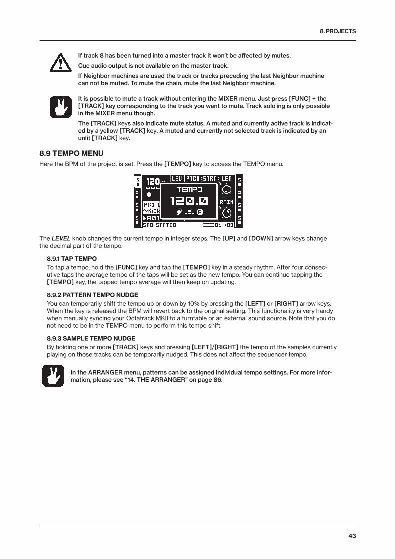
8. PROJECTS
43
If track 8 has been turned into a master track it won’t be affected by mutes.
Cue audio output is not available on the master track.
If Neighbor machines are used the track or tracks preceding the last Neighbor machine can not be muted. To mute the chain, mute the last Neighbor machine.
It is possible to mute a track without entering the MIXER menu. Just press [FUNC] + the [TRACK] key corresponding to the track you want to mute. Track solo’ing is only possible in the MIXER menu though.
The [TRACK] keys also indicate mute status. A muted and currently active track is indicat-ed by a yellow [TRACK] key. A muted and currently not selected track is indicated by an unlit [TRACK] key.
8.9 TEMPO MENUHere the BPM of the project is set. Press the [TEMPO] key to access the TEMPO menu.
The LEVEL knob changes the current tempo in integer steps. The [UP] and [DOWN] arrow keys change the decimal part of the tempo.
8.9.1 TAP TEMPOTo tap a tempo, hold the [FUNC] key and tap the [TEMPO] key in a steady rhythm. After four consec-utive taps the average tempo of the taps will be set as the new tempo. You can continue tapping the [TEMPO] key, the tapped tempo average will then keep on updating.
8.9.2 PATTERN TEMPO NUDGEYou can temporarily shift the tempo up or down by 10% by pressing the [LEFT] or [RIGHT] arrow keys. When the key is released the BPM will revert back to the original setting. This functionality is very handy when manually syncing your Octatrack MKII to a turntable or an external sound source. Note that you do not need to be in the TEMPO menu to perform this tempo shift.
8.9.3 SAMPLE TEMPO NUDGEBy holding one or more [TRACK] keys and pressing [LEFT]/[RIGHT] the tempo of the samples currently playing on those tracks can be temporarily nudged. This does not affect the sequencer tempo.
In the ARRANGER menu, patterns can be assigned individual tempo settings. For more infor-mation, please see “14. THE ARRANGER” on page 86.
9. TRACK RECORDERS AND PICKUP MACHINES
44
9. TRACK RECORDERS AND PICKUP MACHINESThere are two ways to sample with the Octatrack MKII. Either by using track recorder sampling, which can be performed manually or by using recorder trigs, or by using specialized machines called Pickup machines, which essentially work like loopers. Read more about track recorder sampling in the section “9.2 TRACK RECORDER SAMPLING METHODS” on page 47. Pickup machine sampling is covered in section “9.3 PICKUP MACHINE SAMPLING” on page 49.
When performing track recorder sampling or Pickup machine sampling, track recorders are always used. Each project features eight track recorders, one for each track, and they can be set up to record audio from the external inputs, from the main and cue outputs, from the internal tracks and from various combinations of these sources. Track recorders do not have to be assigned to the tracks as they always are available. The RECORDING SETUP menus, covered in section “9.1 RECORDING EDIT AND SETUP MENUS” on page 44., are used to control from which sources and in what way the track recorders should sample.
By default the track recorder memory is used when sampling, meaning each track recorder can sample for about 16 seconds. The reserved track recorder memory can however be increased or decreased. It is even possible for the track recorders to sample directly to the Flex RAM memory. Settings relating to RAM mem-ory distribution is found in the MEMORY menu, which is covered on page 39. Read more about the general handling of RAM memory in section “8.1 PROJECTS AND RAM MEMORY” on page 28.
Samples captured by the track recorders are stored in recorder buffers. The eight recorder buffers are located in the Flex sample slot list. To play back a sample captured via track recorder sampling, the corre-sponding recorder buffer needs to be assigned to a Flex machine of a track. Since track recorder sampling is independent from playback, the same track can be used for both sampling and playback of the sample. It is also possible to assign the same recorder buffer to several Flex machines of a pattern. Each Flex machine track can of course still contain individual settings and sequencer trigs. Read more about recorder buffers in section “9.2.3 PLAYBACK OF CAPTURED RECORDER SAMPLES” on page 48. Playback of recorded Pickup machine samples works a bit differently. If a Pickup machine is assigned to a track, it will be hard-linked to both the track recorder and recorder buffer of that track. No recorder buffers thus need to be assigned for Pickup machines to play back recorded samples. Samples captured by Pickup machines are still stored in the recorder buffers though, making it possible to save and edit these recordings.
Recorder buffer content is not automatically saved. If a recorder buffer contains a sample and the corre-sponding track recorder starts to sample, the original buffer sample will be overwritten by the new sample. Also, samples in the recorder buffers are not retained in memory after switching off the Octatrack MKII or changing projects. If you want to keep recorder buffer samples they need to be saved to the Compact Flash card. This operation can be performed in the RECORDING SETUP EDIT menu, accessed by press-ing [FUNC] + [REC3]. Alternatively, saving can be done from within the audio editor. This is covered in the section “13.2.5 FILE” on page 85.
For tutorials on how to sample, please, see “17.1 TRACK RECORDER SAMPLING” on page 103.
Captured samples can be saved either directly in the audio pool or in the project folder. The setting controlling this is found in the PERSONALIZE menu. For more information, please see “8.5.4 PERSONALIZE” on page 33.
Recorded samples can immediately be time stretched or time compressed to match the BPM of the Octatrack MKII. Note that TSTR in the SRC SETUP menu must be set to either AUTO, NORM or BEAT for this to function. If set to AUTO, make sure time stretch is activated for the recorder buffer. That is done in the ATTRIBUTES menu of the audio editor. For more informa-tion, please see “13.2.4 ATTRIBUTES” on page 83.
The samples captured by the track recorders can be opened directly in the audio editor for further editing. First select the track whose corresponding recorder buffer sample should be edited. Then press [REC1/2] + [BANK] to open the recorder buffer sample in the audio editor. Read more about the audio editor in section “13. THE AUDIO EDITOR” on page 79. The audio editor can also be accessed from the RECORDING SETUP EDIT menu. Access this menu by pressing [FUNC] + [REC3].
It is possible to sample even though the DIR parameters in the MIXER menu are set to 0.
It is possible to cue incoming audio by pressing [CUE] + [REC1/2] keys.
9.1 RECORDING EDIT AND SETUP MENUSEach track recorder features two dedicated RECORDING SETUP pages, where settings relating to what and how the track recorder should sample are found. Placing recorder trigs on the step sequencer, which is needed for recorder trig sampling, is also carried out while either of the two menu pages is active. As track

9. TRACK RECORDERS AND PICKUP MACHINES
45
recorders are directly linked to the tracks, the track whose track recorder you wish to edit must be active.
Pressing [FUNC] + [PLAY] while inside the RECORDING SETUP menus will clear the recorder buffer of the active track recorder from any audio content. GRID RECORDING mode needs to be inactive for this to function.
9.1.1 RECORDING EDIT MENUPress [FUNC] + [REC3]. to open the RECORDING EDIT menu. This menu offers various commands relating to the track recorder.
EDIT THIS RECORDING will open the recorded sample in the audio editor. For more information, please see “13. THE AUDIO EDITOR” on page 79.
SAVE THIS RECORDING will save the recording made by the active track recorder to the Compact Flash card.
SAVE ALL RECORDINGS will save all recordings of all track recorders to the Compact Flash card.
GO TO MEMORY CONFIG will open the MEMORY menu, where the allocation of the RAM memory can be set. For more information, please see “8.6.5 MEMORY” on page 38.
9.1.2 RECORDING SETUP 1 MENUEnter RECORDING SETUP 1 menu by pressing [FUNC] + [REC1].
The bar at the bottom of the window indicates track recorder sampling and playback. It represents the length (or projected length) of the recorder buffer. The two arrows visible when sampling or playing back samples show the record- and playback positions. The top arrow, pointing towards the bar, shows the recording position. The bottom arrow shows the playback position. To the right of the bar, the amount of sampling time available to the active track recorder is expressed in seconds as well as in sequencer steps.
When sampling or playing back a recorded sample, the tape recorder wheel will start to spin.
INAB selects which input or inputs of the input pair AB the recorder should sample from.
• - makes the recorder disregard input AB when sampling.
• A B makes the recorder capture a stereo file in which the signal from input A is panned hard left and the signal from input B is panned hard right. This is the default option.
• A makes the recorder sample from input A. The captured sample will be in stereo even though only one input is used.
• B makes the recorder sample from input B. The captured sample will be in stereo even though only one input is used.
• A+B makes the recorder capture a stereo file in which the signals from input A and input B are summed.
INCD selects which input or inputs of the input pair CD the recorder should sample from. Five options exist.
• - makes the recorder disregard input CD when sampling.
• C D makes the recorder capture a stereo file in which the signal from input C is panned hard left and the signal from input D is panned hard right. This is the default option.
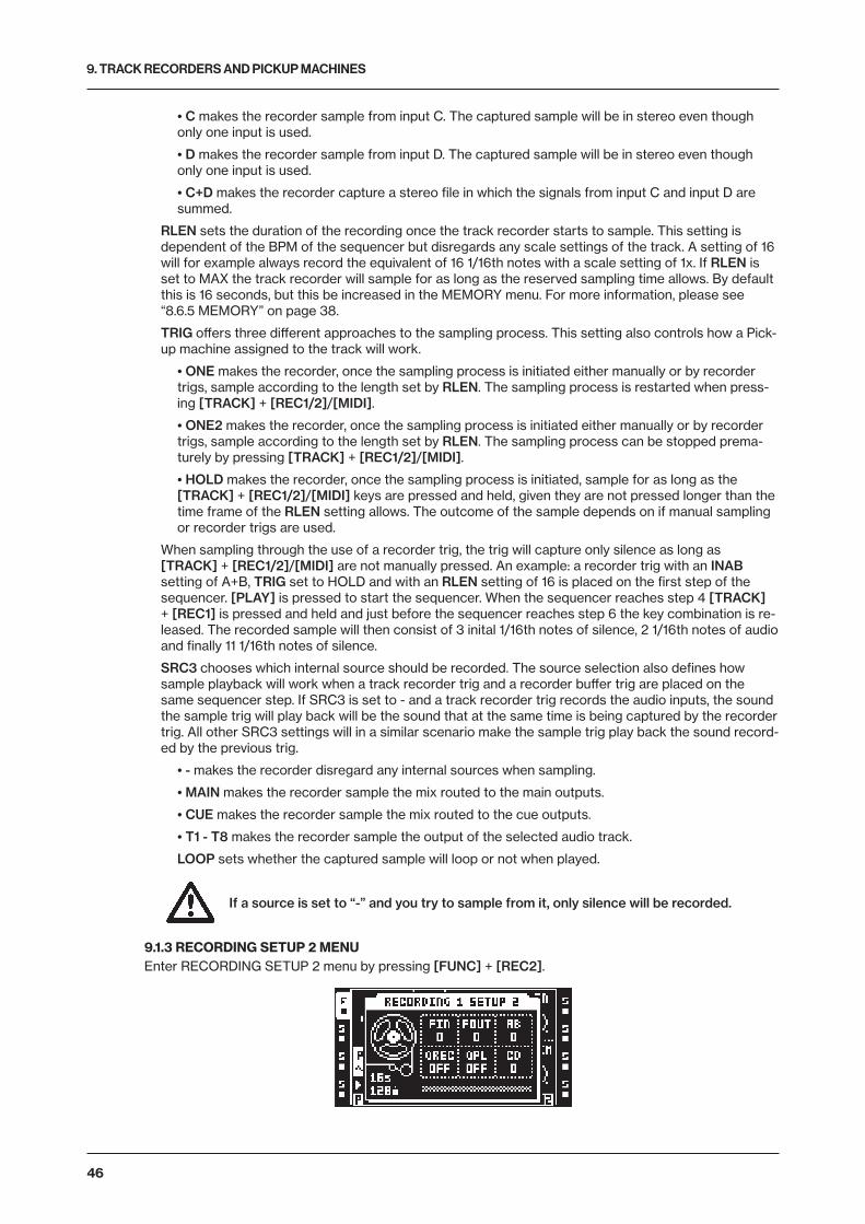
9. TRACK RECORDERS AND PICKUP MACHINES
46
• C makes the recorder sample from input C. The captured sample will be in stereo even though only one input is used.
• D makes the recorder sample from input D. The captured sample will be in stereo even though only one input is used.
• C+D makes the recorder capture a stereo file in which the signals from input C and input D are summed.
RLEN sets the duration of the recording once the track recorder starts to sample. This setting is dependent of the BPM of the sequencer but disregards any scale settings of the track. A setting of 16 will for example always record the equivalent of 16 1/16th notes with a scale setting of 1x. If RLEN is set to MAX the track recorder will sample for as long as the reserved sampling time allows. By default this is 16 seconds, but this be increased in the MEMORY menu. For more information, please see “8.6.5 MEMORY” on page 38.
TRIG offers three different approaches to the sampling process. This setting also controls how a Pick-up machine assigned to the track will work.
• ONE makes the recorder, once the sampling process is initiated either manually or by recorder trigs, sample according to the length set by RLEN. The sampling process is restarted when press-ing [TRACK] + [REC1/2]/[MIDI].
• ONE2 makes the recorder, once the sampling process is initiated either manually or by recorder trigs, sample according to the length set by RLEN. The sampling process can be stopped prema-turely by pressing [TRACK] + [REC1/2]/[MIDI].
• HOLD makes the recorder, once the sampling process is initiated, sample for as long as the [TRACK] + [REC1/2]/[MIDI] keys are pressed and held, given they are not pressed longer than the time frame of the RLEN setting allows. The outcome of the sample depends on if manual sampling or recorder trigs are used.
When sampling through the use of a recorder trig, the trig will capture only silence as long as [TRACK] + [REC1/2]/[MIDI] are not manually pressed. An example: a recorder trig with an INAB setting of A+B, TRIG set to HOLD and with an RLEN setting of 16 is placed on the first step of the sequencer. [PLAY] is pressed to start the sequencer. When the sequencer reaches step 4 [TRACK] + [REC1] is pressed and held and just before the sequencer reaches step 6 the key combination is re-leased. The recorded sample will then consist of 3 inital 1/16th notes of silence, 2 1/16th notes of audio and finally 11 1/16th notes of silence.
SRC3 chooses which internal source should be recorded. The source selection also defines how sample playback will work when a track recorder trig and a recorder buffer trig are placed on the same sequencer step. If SRC3 is set to - and a track recorder trig records the audio inputs, the sound the sample trig will play back will be the sound that at the same time is being captured by the recorder trig. All other SRC3 settings will in a similar scenario make the sample trig play back the sound record-ed by the previous trig.
• - makes the recorder disregard any internal sources when sampling.
• MAIN makes the recorder sample the mix routed to the main outputs.
• CUE makes the recorder sample the mix routed to the cue outputs.
• T1 - T8 makes the recorder sample the output of the selected audio track.
LOOP sets whether the captured sample will loop or not when played.
If a source is set to “-” and you try to sample from it, only silence will be recorded.
9.1.3 RECORDING SETUP 2 MENUEnter RECORDING SETUP 2 menu by pressing [FUNC] + [REC2].
9. TRACK RECORDERS AND PICKUP MACHINES
47
FIN applies a fade in when starting the recording. The value is expressed in sequencer steps. Applying a very short fade in can be used to avoid clicks that otherwise might occur when a recorded sample loops.
FOUT applies a fade out to the recording. The value is expressed in sequencer steps. The fade out is added after the recording stops. If for example recording occurs for 16 steps and FOUT is set to 2, the total length of the sample will be 18 sequencer steps. This parameter behaves differently for Pickup machines. In this scenario the fade out will be applied to the beginning of the captured loop.
AB sets the monitoring level of the signal coming from the input pair AB. The setting is only relevant when a Pickup machine is assigned to the track. The INAB setting, located in the RECORDING SETUP 1 page, decides which input or inputs that should be monitored. If different track recorders contain different AB settings, the setting made for the track recorder of active track is the one that will dictate the current Pickup machine monitoring level. The monitor signal is routed to the active track, mean-ing any track effects will affect the signal. It will also be routed to the output destination of the active track. This setting is useful if you want to monitor incoming audio a Pickup machine should sample, but don’t want to use DIR parameter of the MIXER menu.
QREC makes it possible to time quantize manual sampling and Pickup machine sampling.
• OFF disables recording quantization.
• PLEN will, after pressing the keys initiating recording, start the recording process once the pattern has played its full length.
• 1... will time the start of the sampling process according to the set number of sequencer steps. If for example 4 is selected, sampling will start on the next beat. If 8 is selected, sampling will start after half a bar.
QPL makes it possible to quantize manual trigging of the recorder buffers and Pickup machines. Manual trigging is done by for example pressing [TRACK] + [PLAY] or the last eight [TRIG] keys. This parameter has no effect on track recorders trigged by the sequencer. This parameter is a reflection of the QUANTIZED TRIG setting available in the ATTRIBUTES menu found in the audio editor. If the QPL parameter is changed, QUANTIZED TRIG will thus be changed as well, which can be seen when the recorder buffer of the track recorder is opened in the audio editor. For more information, please see “13.2.4 ATTRIBUTES” on page 83.
• OFF makes the recorder buffer immediately play back audio once it is trigged. This is the default option.
• PLEN will, once the recorder buffer has been trigged, start playback once the pattern has played its full length.
• 1... will time the start playback of the recorder buffer according to the set amount of sequencer steps. If for example 4 is selected, playback will start on the next beat. If 8 is selected, playback will start after half a bar.
CD works just like the AB setting, but for inputs CD.
Setting FIN and FOUT to their lowest values will help avoid any unwanted clicks that might occur when a recorded sample loops.
9.2 TRACK RECORDER SAMPLING METHODSTwo main methods of sampling exist. Manual sampling is performed by manually pressing keys while re-corder trig sampling is an automated process conducted by the use of recorder trigs.
9.2.1 MANUAL SAMPLINGManual sampling is done through pressing key combinations. By setting INAB, INCD and SRC3 of the RECORDING SETUP 1 menu appropriately both mono and stereo sources can be sampled.
[TRACK] + [REC1] will sample from the external input AB to the track recorder of the track.
[TRACK] + [REC2] will sample from the external input CD to the track recorder of the track.
[TRACK] + [REC3] will sample internal sounds to the track recorder of the track.
If a recorder buffer contains a sample and the corresponding track recorder starts to sample, the original buffer sample will be overwritten by the new sample.
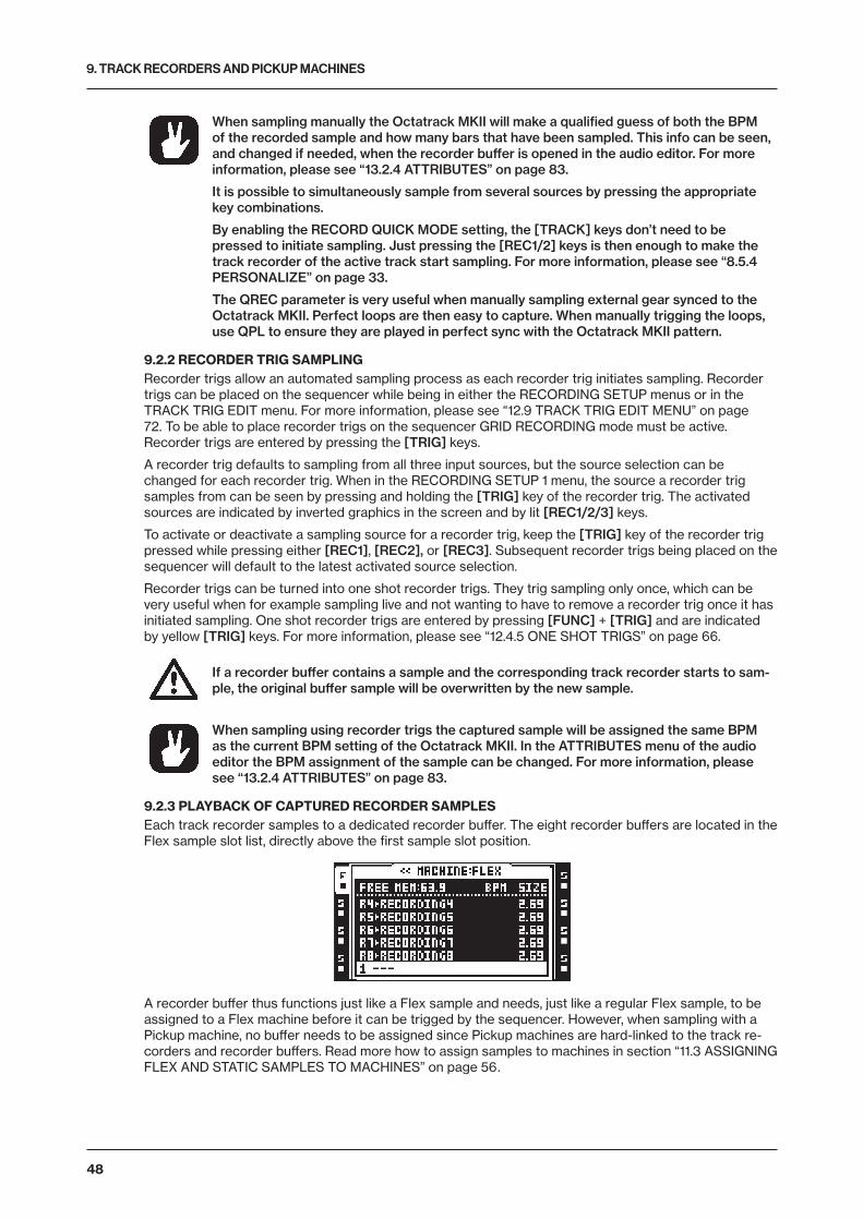
9. TRACK RECORDERS AND PICKUP MACHINES
48
When sampling manually the Octatrack MKII will make a qualified guess of both the BPM of the recorded sample and how many bars that have been sampled. This info can be seen, and changed if needed, when the recorder buffer is opened in the audio editor. For more information, please see “13.2.4 ATTRIBUTES” on page 83.
It is possible to simultaneously sample from several sources by pressing the appropriate key combinations.
By enabling the RECORD QUICK MODE setting, the [TRACK] keys don’t need to be pressed to initiate sampling. Just pressing the [REC1/2] keys is then enough to make the track recorder of the active track start sampling. For more information, please see “8.5.4 PERSONALIZE” on page 33.
The QREC parameter is very useful when manually sampling external gear synced to the Octatrack MKII. Perfect loops are then easy to capture. When manually trigging the loops, use QPL to ensure they are played in perfect sync with the Octatrack MKII pattern.
9.2.2 RECORDER TRIG SAMPLINGRecorder trigs allow an automated sampling process as each recorder trig initiates sampling. Recorder trigs can be placed on the sequencer while being in either the RECORDING SETUP menus or in the TRACK TRIG EDIT menu. For more information, please see “12.9 TRACK TRIG EDIT MENU” on page 72. To be able to place recorder trigs on the sequencer GRID RECORDING mode must be active. Recorder trigs are entered by pressing the [TRIG] keys.
A recorder trig defaults to sampling from all three input sources, but the source selection can be changed for each recorder trig. When in the RECORDING SETUP 1 menu, the source a recorder trig samples from can be seen by pressing and holding the [TRIG] key of the recorder trig. The activated sources are indicated by inverted graphics in the screen and by lit [REC1/2/3] keys.
To activate or deactivate a sampling source for a recorder trig, keep the [TRIG] key of the recorder trig pressed while pressing either [REC1], [REC2], or [REC3]. Subsequent recorder trigs being placed on the sequencer will default to the latest activated source selection.
Recorder trigs can be turned into one shot recorder trigs. They trig sampling only once, which can be very useful when for example sampling live and not wanting to have to remove a recorder trig once it has initiated sampling. One shot recorder trigs are entered by pressing [FUNC] + [TRIG] and are indicated by yellow [TRIG] keys. For more information, please see “12.4.5 ONE SHOT TRIGS” on page 66.
If a recorder buffer contains a sample and the corresponding track recorder starts to sam-ple, the original buffer sample will be overwritten by the new sample.
When sampling using recorder trigs the captured sample will be assigned the same BPM as the current BPM setting of the Octatrack MKII. In the ATTRIBUTES menu of the audio editor the BPM assignment of the sample can be changed. For more information, please see “13.2.4 ATTRIBUTES” on page 83.
9.2.3 PLAYBACK OF CAPTURED RECORDER SAMPLESEach track recorder samples to a dedicated recorder buffer. The eight recorder buffers are located in the Flex sample slot list, directly above the first sample slot position.
A recorder buffer thus functions just like a Flex sample and needs, just like a regular Flex sample, to be assigned to a Flex machine before it can be trigged by the sequencer. However, when sampling with a Pickup machine, no buffer needs to be assigned since Pickup machines are hard-linked to the track re-corders and recorder buffers. Read more how to assign samples to machines in section “11.3 ASSIGNING FLEX AND STATIC SAMPLES TO MACHINES” on page 56.
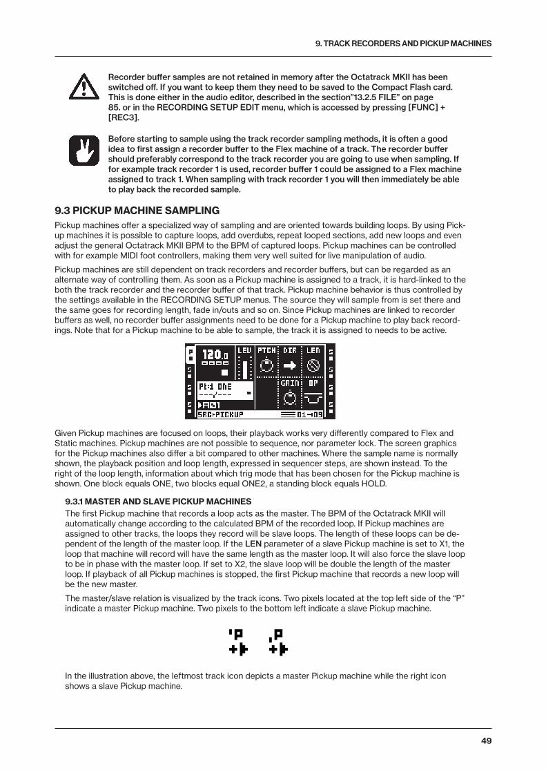
9. TRACK RECORDERS AND PICKUP MACHINES
49
Recorder buffer samples are not retained in memory after the Octatrack MKII has been switched off. If you want to keep them they need to be saved to the Compact Flash card. This is done either in the audio editor, described in the section”13.2.5 FILE” on page 85. or in the RECORDING SETUP EDIT menu, which is accessed by pressing [FUNC] + [REC3].
Before starting to sample using the track recorder sampling methods, it is often a good idea to first assign a recorder buffer to the Flex machine of a track. The recorder buffer should preferably correspond to the track recorder you are going to use when sampling. If for example track recorder 1 is used, recorder buffer 1 could be assigned to a Flex machine assigned to track 1. When sampling with track recorder 1 you will then immediately be able to play back the recorded sample.
9.3 PICKUP MACHINE SAMPLINGPickup machines offer a specialized way of sampling and are oriented towards building loops. By using Pick-up machines it is possible to capture loops, add overdubs, repeat looped sections, add new loops and even adjust the general Octatrack MKII BPM to the BPM of captured loops. Pickup machines can be controlled with for example MIDI foot controllers, making them very well suited for live manipulation of audio.
Pickup machines are still dependent on track recorders and recorder buffers, but can be regarded as an alternate way of controlling them. As soon as a Pickup machine is assigned to a track, it is hard-linked to the both the track recorder and the recorder buffer of that track. Pickup machine behavior is thus controlled by the settings available in the RECORDING SETUP menus. The source they will sample from is set there and the same goes for recording length, fade in/outs and so on. Since Pickup machines are linked to recorder buffers as well, no recorder buffer assignments need to be done for a Pickup machine to play back record-ings. Note that for a Pickup machine to be able to sample, the track it is assigned to needs to be active.
Given Pickup machines are focused on loops, their playback works very differently compared to Flex and Static machines. Pickup machines are not possible to sequence, nor parameter lock. The screen graphics for the Pickup machines also differ a bit compared to other machines. Where the sample name is normally shown, the playback position and loop length, expressed in sequencer steps, are shown instead. To the right of the loop length, information about which trig mode that has been chosen for the Pickup machine is shown. One block equals ONE, two blocks equal ONE2, a standing block equals HOLD.
9.3.1 MASTER AND SLAVE PICKUP MACHINESThe first Pickup machine that records a loop acts as the master. The BPM of the Octatrack MKII will automatically change according to the calculated BPM of the recorded loop. If Pickup machines are assigned to other tracks, the loops they record will be slave loops. The length of these loops can be de-pendent of the length of the master loop. If the LEN parameter of a slave Pickup machine is set to X1, the loop that machine will record will have the same length as the master loop. It will also force the slave loop to be in phase with the master loop. If set to X2, the slave loop will be double the length of the master loop. If playback of all Pickup machines is stopped, the first Pickup machine that records a new loop will be the new master.
The master/slave relation is visualized by the track icons. Two pixels located at the top left side of the “P” indicate a master Pickup machine. Two pixels to the bottom left indicate a slave Pickup machine.
In the illustration above, the leftmost track icon depicts a master Pickup machine while the right icon shows a slave Pickup machine.
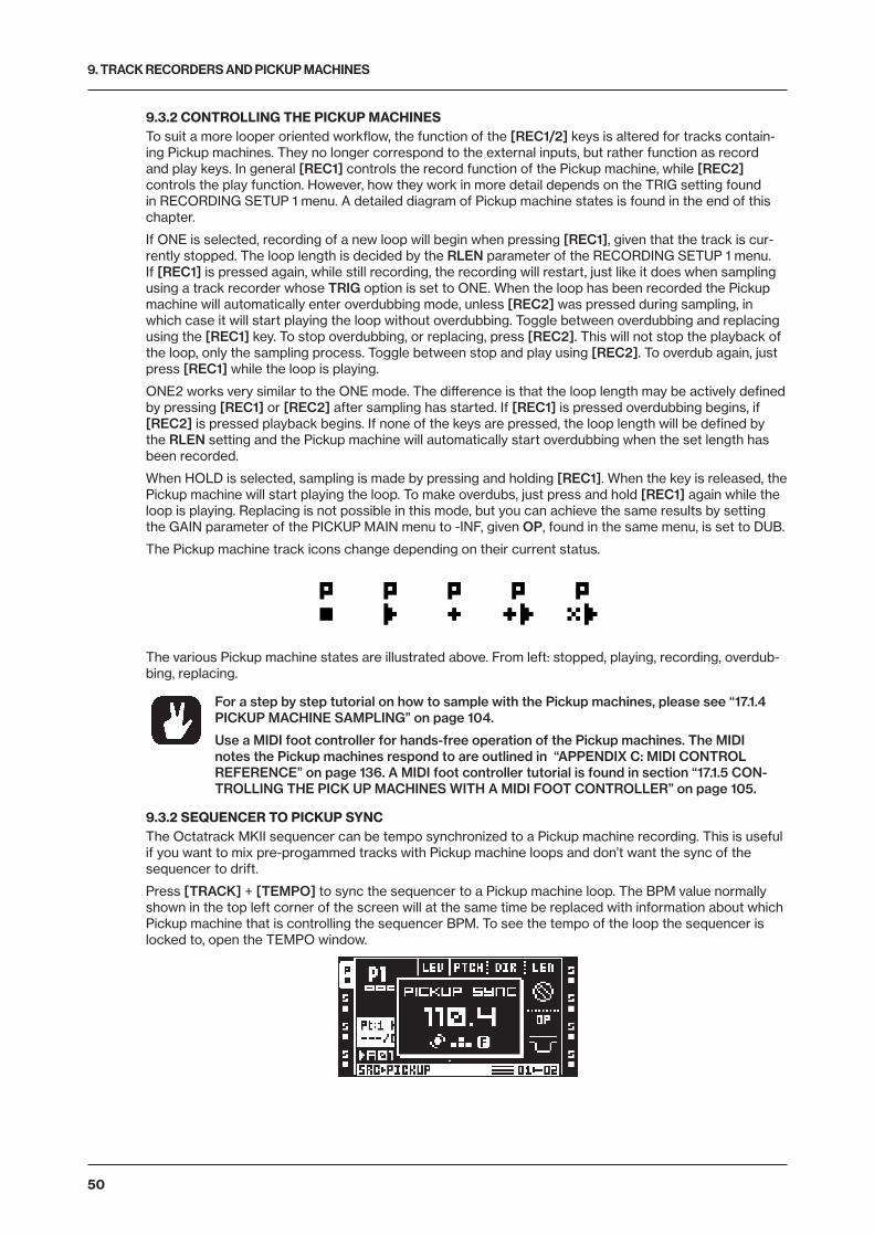
9. TRACK RECORDERS AND PICKUP MACHINES
50
9.3.2 CONTROLLING THE PICKUP MACHINESTo suit a more looper oriented workflow, the function of the [REC1/2] keys is altered for tracks contain-ing Pickup machines. They no longer correspond to the external inputs, but rather function as record and play keys. In general [REC1] controls the record function of the Pickup machine, while [REC2] controls the play function. However, how they work in more detail depends on the TRIG setting found in RECORDING SETUP 1 menu. A detailed diagram of Pickup machine states is found in the end of this chapter.
If ONE is selected, recording of a new loop will begin when pressing [REC1], given that the track is cur-rently stopped. The loop length is decided by the RLEN parameter of the RECORDING SETUP 1 menu. If [REC1] is pressed again, while still recording, the recording will restart, just like it does when sampling using a track recorder whose TRIG option is set to ONE. When the loop has been recorded the Pickup machine will automatically enter overdubbing mode, unless [REC2] was pressed during sampling, in which case it will start playing the loop without overdubbing. Toggle between overdubbing and replacing using the [REC1] key. To stop overdubbing, or replacing, press [REC2]. This will not stop the playback of the loop, only the sampling process. Toggle between stop and play using [REC2]. To overdub again, just press [REC1] while the loop is playing.
ONE2 works very similar to the ONE mode. The difference is that the loop length may be actively defined by pressing [REC1] or [REC2] after sampling has started. If [REC1] is pressed overdubbing begins, if [REC2] is pressed playback begins. If none of the keys are pressed, the loop length will be defined by the RLEN setting and the Pickup machine will automatically start overdubbing when the set length has been recorded.
When HOLD is selected, sampling is made by pressing and holding [REC1]. When the key is released, the Pickup machine will start playing the loop. To make overdubs, just press and hold [REC1] again while the loop is playing. Replacing is not possible in this mode, but you can achieve the same results by setting the GAIN parameter of the PICKUP MAIN menu to -INF, given OP, found in the same menu, is set to DUB.
The Pickup machine track icons change depending on their current status.
The various Pickup machine states are illustrated above. From left: stopped, playing, recording, overdub-bing, replacing.
For a step by step tutorial on how to sample with the Pickup machines, please see “17.1.4 PICKUP MACHINE SAMPLING” on page 104.
Use a MIDI foot controller for hands-free operation of the Pickup machines. The MIDI notes the Pickup machines respond to are outlined in “APPENDIX C: MIDI CONTROL REFERENCE” on page 136. A MIDI foot controller tutorial is found in section “17.1.5 CON-TROLLING THE PICK UP MACHINES WITH A MIDI FOOT CONTROLLER” on page 105.
9.3.2 SEQUENCER TO PICKUP SYNCThe Octatrack MKII sequencer can be tempo synchronized to a Pickup machine recording. This is useful if you want to mix pre-progammed tracks with Pickup machine loops and don’t want the sync of the sequencer to drift.
Press [TRACK] + [TEMPO] to sync the sequencer to a Pickup machine loop. The BPM value normally shown in the top left corner of the screen will at the same time be replaced with information about which Pickup machine that is controlling the sequencer BPM. To see the tempo of the loop the sequencer is locked to, open the TEMPO window.
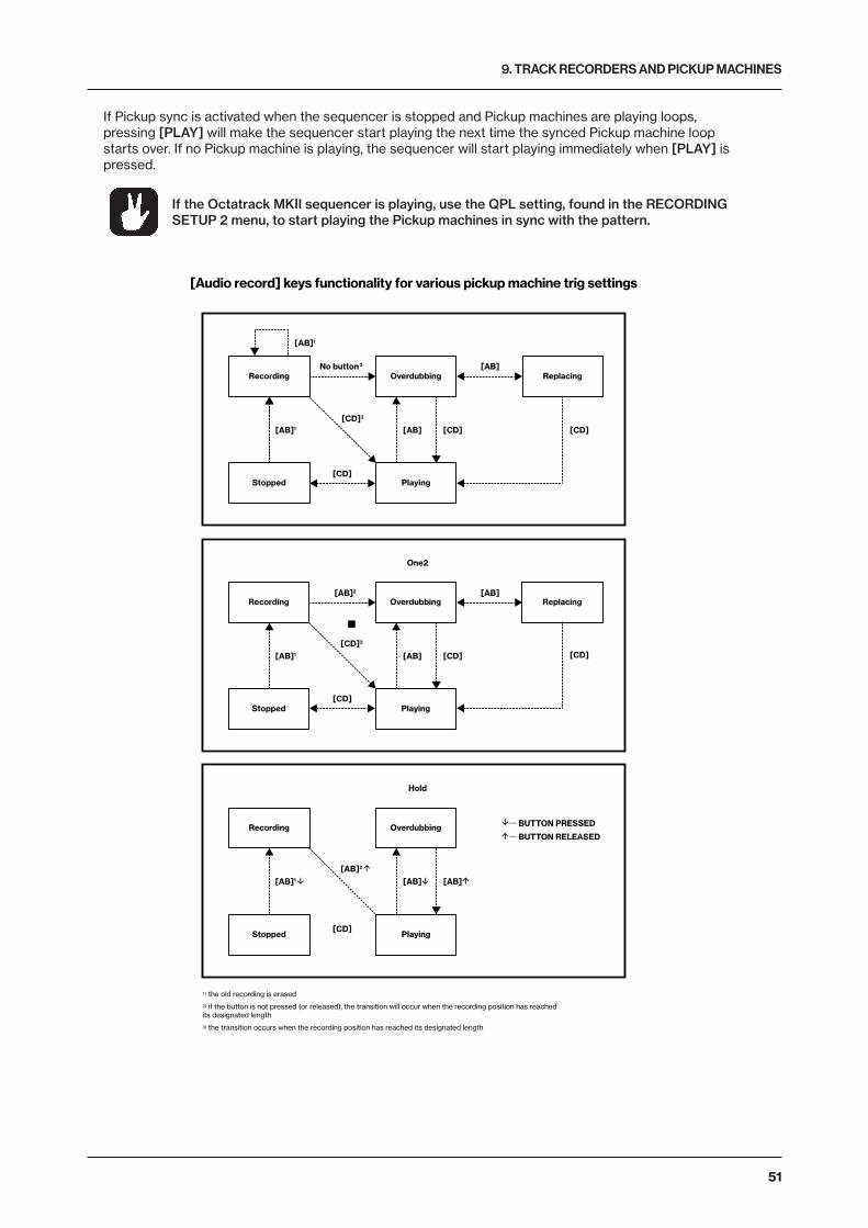
9. TRACK RECORDERS AND PICKUP MACHINES
51
If Pickup sync is activated when the sequencer is stopped and Pickup machines are playing loops, pressing [PLAY] will make the sequencer start playing the next time the synced Pickup machine loop starts over. If no Pickup machine is playing, the sequencer will start playing immediately when [PLAY] is pressed.
If the Octatrack MKII sequencer is playing, use the QPL setting, found in the RECORDING SETUP 2 menu, to start playing the Pickup machines in sync with the pattern.
[AB]
[AB]2
[AB][AB]1
1 ) the old recording is erased
2) if the button is not pressed (or released), the transition will occur when the recording position has reachedits designated length
3) the transition occurs when the recording position has reached its designated length
— BUTTON PRESSED— BUTTON RELEASED
[CD]
Hold
Recording
Stopped Playing
Overdubbing
Recording
Stopped Playing
Overdubbing Replacing
[AB]1
[AB]
[CD][CD]3
[CD]
[AB][AB]1
No button3
[Audio record] keys functionality for various pickup machine trig settings
Recording
Stopped Playing
Overdubbing Replacing[AB][AB]2
One2
[CD][AB]
[CD]
[CD][AB]1
[CD]3
[CD]
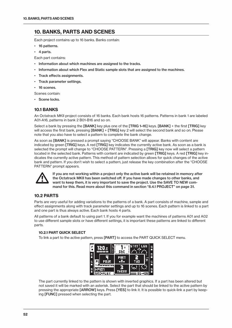
10. BANKS, PARTS AND SCENES
52
10. BANKS, PARTS AND SCENESEach project contains up to 16 banks. Banks contain:
• 16 patterns.
• 4 parts.
Each part contains:
• Information about which machines are assigned to the tracks.
• Information about which Flex and Static sample slots that are assigned to the machines.
• Track effects assignments.
• Track parameter settings.
• 16 scenes.
Scenes contain:
• Scene locks.
10.1 BANKSAn Octatrack MKII project consists of 16 banks. Each bank hosts 16 patterns. Patterns in bank 1 are labeled A01-A16, patterns in bank 2 B01-B16 and so on.
Select a bank by pressing the [BANK] key plus one of the [TRIG 1–16] keys. [BANK] + the first [TRIG] key will access the first bank, pressing [BANK] + [TRIG] key 2 will select the second bank and so on. Please note that you also have to select a pattern to complete the bank change.
As soon as [BANK] is pressed a prompt saying “CHOOSE BANK” will appear. Banks with content are indicated by green [TRIG] keys. A red [TRIG] key indicates the currently active bank. As soon as a bank is selected the prompt will change to “CHOOSE PATTERN”. Pressing a [TRIG] key now will select a pattern located in the selected bank. Patterns with content are indicated by green [TRIG] keys. A red [TRIG] key in-dicates the currently active pattern. This method of pattern selection allows for quick changes of the active bank and pattern. If you don’t wish to select a pattern, just release the key combination after the “CHOOSE PATTERN” prompt appears.
If you are not working within a project only the active bank will be retained in memory after the Octatrack MKII has been switched off. If you have made changes to other banks, and want to keep them, it is very important to save the project. Use the SAVE TO NEW com-mand for this. Read more about this command in section “8.4.1 PROJECT” on page 31.
10.2 PARTSParts are very useful for adding variations to the patterns of a bank. A part consists of machine, sample and effect assignments along with track parameter settings and up to 16 scenes. Each pattern is linked to a part and one part is thus always active. Each bank hosts 4 parts.
All patterns of a bank default to using part 1. If you for example want the machines of patterns A01 and A02 to use different sample slots or have different settings, it is important these patterns are linked to different parts.
10.2.1 PART QUICK SELECTTo link a part to the active pattern, press [PART] to access the PART QUICK SELECT menu.
The part currently linked to the pattern is shown with inverted graphics. If a part has been altered but not saved it will be marked with an asterisk. Select the part that should be linked to the active pattern by pressing the appropriate [ARROW] keys. Press [YES] to link it. It is possible to quick-link a part by keep-ing [FUNC] pressed when selecting the part.
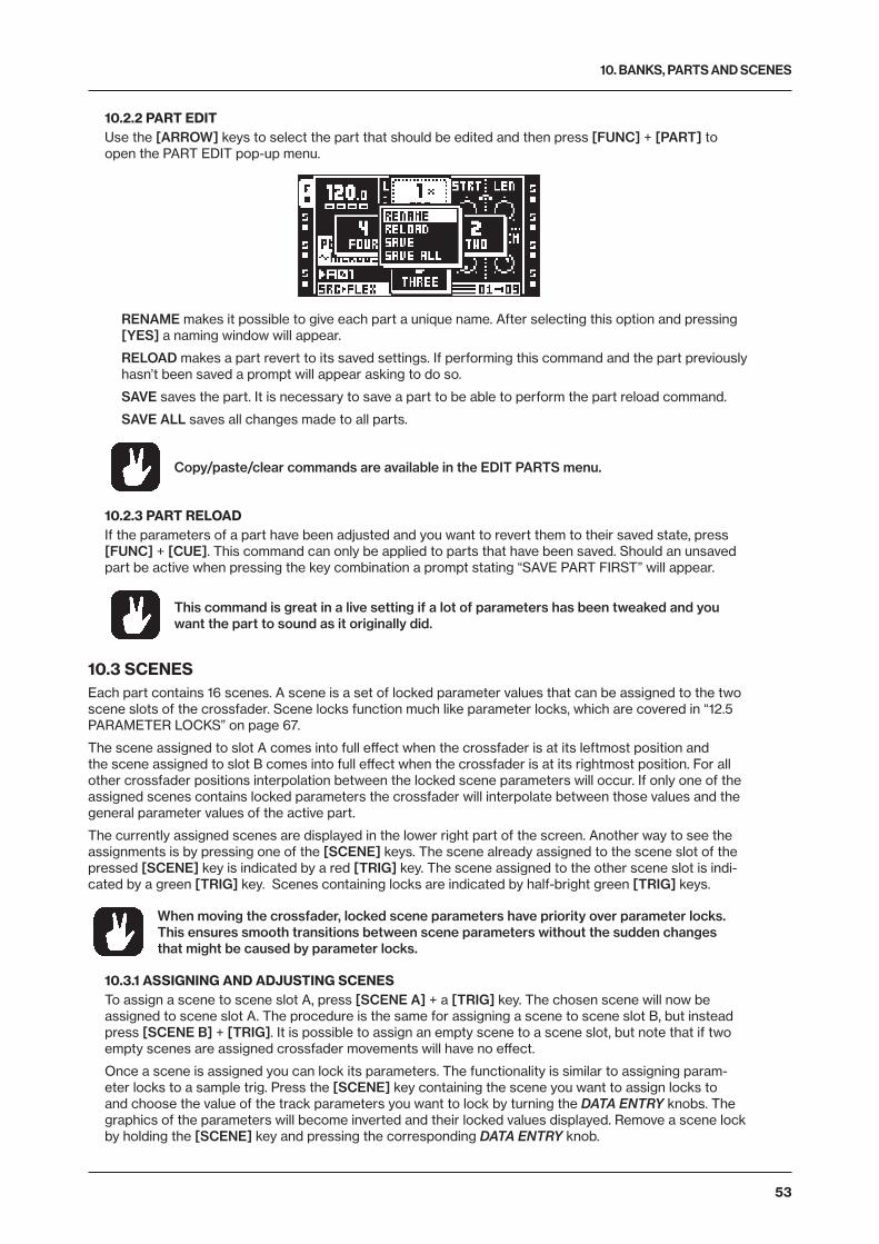
10. BANKS, PARTS AND SCENES
53
10.2.2 PART EDITUse the [ARROW] keys to select the part that should be edited and then press [FUNC] + [PART] to open the PART EDIT pop-up menu.
RENAME makes it possible to give each part a unique name. After selecting this option and pressing [YES] a naming window will appear.
RELOAD makes a part revert to its saved settings. If performing this command and the part previously hasn’t been saved a prompt will appear asking to do so.
SAVE saves the part. It is necessary to save a part to be able to perform the part reload command.
SAVE ALL saves all changes made to all parts.
Copy/paste/clear commands are available in the EDIT PARTS menu.
10.2.3 PART RELOADIf the parameters of a part have been adjusted and you want to revert them to their saved state, press [FUNC] + [CUE]. This command can only be applied to parts that have been saved. Should an unsaved part be active when pressing the key combination a prompt stating “SAVE PART FIRST” will appear.
This command is great in a live setting if a lot of parameters has been tweaked and you want the part to sound as it originally did.
10.3 SCENESEach part contains 16 scenes. A scene is a set of locked parameter values that can be assigned to the two scene slots of the crossfader. Scene locks function much like parameter locks, which are covered in “12.5 PARAMETER LOCKS” on page 67.
The scene assigned to slot A comes into full effect when the crossfader is at its leftmost position and the scene assigned to slot B comes into full effect when the crossfader is at its rightmost position. For all other crossfader positions interpolation between the locked scene parameters will occur. If only one of the assigned scenes contains locked parameters the crossfader will interpolate between those values and the general parameter values of the active part.
The currently assigned scenes are displayed in the lower right part of the screen. Another way to see the assignments is by pressing one of the [SCENE] keys. The scene already assigned to the scene slot of the pressed [SCENE] key is indicated by a red [TRIG] key. The scene assigned to the other scene slot is indi-cated by a green [TRIG] key. Scenes containing locks are indicated by half-bright green [TRIG] keys.
When moving the crossfader, locked scene parameters have priority over parameter locks. This ensures smooth transitions between scene parameters without the sudden changes that might be caused by parameter locks.
10.3.1 ASSIGNING AND ADJUSTING SCENESTo assign a scene to scene slot A, press [SCENE A] + a [TRIG] key. The chosen scene will now be assigned to scene slot A. The procedure is the same for assigning a scene to scene slot B, but instead press [SCENE B] + [TRIG]. It is possible to assign an empty scene to a scene slot, but note that if two empty scenes are assigned crossfader movements will have no effect.
Once a scene is assigned you can lock its parameters. The functionality is similar to assigning param-eter locks to a sample trig. Press the [SCENE] key containing the scene you want to assign locks to and choose the value of the track parameters you want to lock by turning the DATA ENTRY knobs. The graphics of the parameters will become inverted and their locked values displayed. Remove a scene lock by holding the [SCENE] key and pressing the corresponding DATA ENTRY knob.
10. BANKS, PARTS AND SCENES
54
To quickly see which tracks and TRACK PARAMETER pages that contain scene locks, press and hold a [SCENE] key. The [TRACK] keys of all tracks containing scene locks will turn half-bright green and/or start to blink. Selecting one of these tracks will show half-bright green and/or blinking [TRACK PARAM-ETER] keys. They indicate which TRACK PARAMETER pages that contain scene locks.
10.3.2 SCENE VOLUME LOCKINGCertain parameters specially made for volume fades are available exclusively to scenes. The XLV, XVOL and XDIR parameters can be regarded as a set of extra volume controllers on top of the LEVEL, VOL and DIR parameters. The difference lies in the way they handle volume fades. Locking them accordingly will make the crossfader fade between the volume of the tracks or inputs in an equal energy fashion. This way of locking volumes is suitable when wanting to avoid the volume dip that otherwise would occur when the crossfader is used to fade between two tracks and reaches the center position.
The parameters are only visible when keeping a [SCENE] key pressed. The XLV parameter is found as an overlay to the LEVEL parameter found in all TRACK PARAMETER pages. The XVOL parameter is found in the AMP MAIN menu. The XDIR AB and XDIR CD parameters are found in the MIXER menu.
The XLV parameter can be locked to two settings.
MIN will mute the signal, post track effects.
MAX will let signal through at the set LEVEL signal level.
The XVOL parameter (on the AMP menu) can be locked to two settings.
MIN will mute the signal, pre track effects.
MAX will let signal through at the set VOL signal level.
The two XDIR parameters (on the MIXER menu) can each be locked to two settings.
MIN will mute the signal.
MAX will let signal through at the set DIR signal level.
Pressing the LEVEL knob while holding down the [SCENE] key pressed will remove the LEVEL lock. An XVOL lock is removed by pressing the corresponding DATA ENTRY knob while keeping the [SCENE] key pressed. An XDIR AB lock is removed by pressing knob B while keeping the [SCENE] key pressed. XDIR CD is removed by pressing knob C while keeping the [SCENE] key pressed.
10.3.3 SCENE MUTEMute a scene assigned to a scene slot by pressing [FUNC] + [SCENE A]/[SCENE B]. When muting a scene the locked parameters of assigned scene will be disregarded and instead the general parameter values of the active part will come into effect. This makes it possible, given the scene parameter values are locked accordingly and the position of the crossfader fully activates the scene, to for example apply washes of effects by unmuting a muted scene.
10.3.4 SCENE COPYIt is possible to copy a scene and paste it to a new scene location.
To copy a scene assigned to scene slot A or B, press and hold a [SCENE] key and press [RECORD]. A window saying “COPY SCENE” will appear. Paste a scene by holding a [SCENE] key and pressing [STOP]. A window showing “PASTE SCENE” will be shown. The copied scene will be pasted to the loca-tion of the scene assigned to the scene slot.
10.3.5 SCENE CLEARIt is possible to clear all scene parameter lock data from a scene.
Hold a [SCENE] key and press [PLAY]. A window saying “CLEAR SCENE” will appear. The scene as-signed to the scene slot will be cleared.
The clear scene operation can be undone by performing the operation one more time. The message “UNDO SCENE” will be shown in the display.
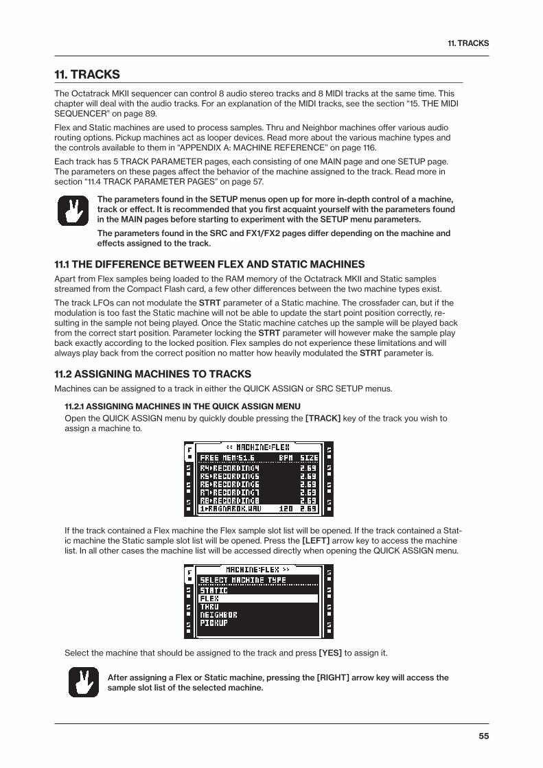
11. TRACKS
55
11. TRACKSThe Octatrack MKII sequencer can control 8 audio stereo tracks and 8 MIDI tracks at the same time. This chapter will deal with the audio tracks. For an explanation of the MIDI tracks, see the section “15. THE MIDI SEQUENCER” on page 89.
Flex and Static machines are used to process samples. Thru and Neighbor machines offer various audio routing options. Pickup machines act as looper devices. Read more about the various machine types and the controls available to them in “APPENDIX A: MACHINE REFERENCE” on page 116.
Each track has 5 TRACK PARAMETER pages, each consisting of one MAIN page and one SETUP page. The parameters on these pages affect the behavior of the machine assigned to the track. Read more in section “11.4 TRACK PARAMETER PAGES” on page 57.
The parameters found in the SETUP menus open up for more in-depth control of a machine, track or effect. It is recommended that you first acquaint yourself with the parameters found in the MAIN pages before starting to experiment with the SETUP menu parameters.
The parameters found in the SRC and FX1/FX2 pages differ depending on the machine and effects assigned to the track.
11.1 THE DIFFERENCE BETWEEN FLEX AND STATIC MACHINESApart from Flex samples being loaded to the RAM memory of the Octatrack MKII and Static samples streamed from the Compact Flash card, a few other differences between the two machine types exist.
The track LFOs can not modulate the STRT parameter of a Static machine. The crossfader can, but if the modulation is too fast the Static machine will not be able to update the start point position correctly, re-sulting in the sample not being played. Once the Static machine catches up the sample will be played back from the correct start position. Parameter locking the STRT parameter will however make the sample play back exactly according to the locked position. Flex samples do not experience these limitations and will always play back from the correct position no matter how heavily modulated the STRT parameter is.
11.2 ASSIGNING MACHINES TO TRACKSMachines can be assigned to a track in either the QUICK ASSIGN or SRC SETUP menus.
11.2.1 ASSIGNING MACHINES IN THE QUICK ASSIGN MENUOpen the QUICK ASSIGN menu by quickly double pressing the [TRACK] key of the track you wish to assign a machine to.
If the track contained a Flex machine the Flex sample slot list will be opened. If the track contained a Stat-ic machine the Static sample slot list will be opened. Press the [LEFT] arrow key to access the machine list. In all other cases the machine list will be accessed directly when opening the QUICK ASSIGN menu.
Select the machine that should be assigned to the track and press [YES] to assign it.
After assigning a Flex or Static machine, pressing the [RIGHT] arrow key will access the sample slot list of the selected machine.
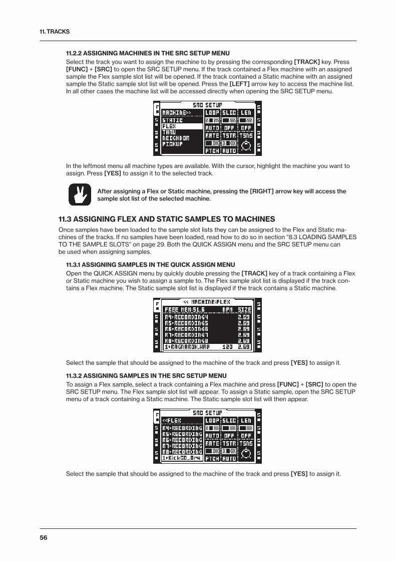
11. TRACKS
56
11.2.2 ASSIGNING MACHINES IN THE SRC SETUP MENUSelect the track you want to assign the machine to by pressing the corresponding [TRACK] key. Press [FUNC] + [SRC] to open the SRC SETUP menu. If the track contained a Flex machine with an assigned sample the Flex sample slot list will be opened. If the track contained a Static machine with an assigned sample the Static sample slot list will be opened. Press the [LEFT] arrow key to access the machine list. In all other cases the machine list will be accessed directly when opening the SRC SETUP menu.
In the leftmost menu all machine types are available. With the cursor, highlight the machine you want to assign. Press [YES] to assign it to the selected track.
After assigning a Flex or Static machine, pressing the [RIGHT] arrow key will access the sample slot list of the selected machine.
11.3 ASSIGNING FLEX AND STATIC SAMPLES TO MACHINESOnce samples have been loaded to the sample slot lists they can be assigned to the Flex and Static ma-chines of the tracks. If no samples have been loaded, read how to do so in section “8.3 LOADING SAMPLES TO THE SAMPLE SLOTS” on page 29. Both the QUICK ASSIGN menu and the SRC SETUP menu can be used when assigning samples.
11.3.1 ASSIGNING SAMPLES IN THE QUICK ASSIGN MENUOpen the QUICK ASSIGN menu by quickly double pressing the [TRACK] key of a track containing a Flex or Static machine you wish to assign a sample to. The Flex sample slot list is displayed if the track con-tains a Flex machine. The Static sample slot list is displayed if the track contains a Static machine.
Select the sample that should be assigned to the machine of the track and press [YES] to assign it.
11.3.2 ASSIGNING SAMPLES IN THE SRC SETUP MENUTo assign a Flex sample, select a track containing a Flex machine and press [FUNC] + [SRC] to open the SRC SETUP menu. The Flex sample slot list will appear. To assign a Static sample, open the SRC SETUP menu of a track containing a Static machine. The Static sample slot list will then appear.
Select the sample that should be assigned to the machine of the track and press [YES] to assign it.
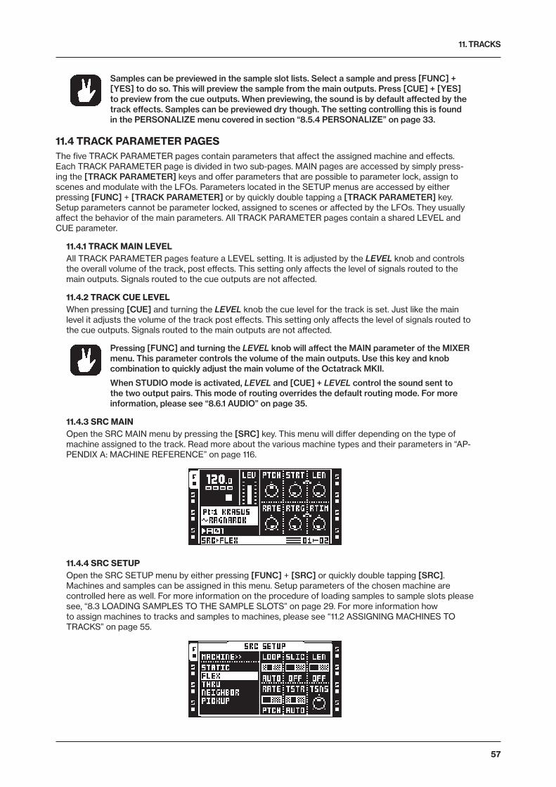
11. TRACKS
57
Samples can be previewed in the sample slot lists. Select a sample and press [FUNC] + [YES] to do so. This will preview the sample from the main outputs. Press [CUE] + [YES] to preview from the cue outputs. When previewing, the sound is by default affected by the track effects. Samples can be previewed dry though. The setting controlling this is found in the PERSONALIZE menu covered in section “8.5.4 PERSONALIZE” on page 33.
11.4 TRACK PARAMETER PAGESThe five TRACK PARAMETER pages contain parameters that affect the assigned machine and effects. Each TRACK PARAMETER page is divided in two sub-pages. MAIN pages are accessed by simply press-ing the [TRACK PARAMETER] keys and offer parameters that are possible to parameter lock, assign to scenes and modulate with the LFOs. Parameters located in the SETUP menus are accessed by either pressing [FUNC] + [TRACK PARAMETER] or by quickly double tapping a [TRACK PARAMETER] key. Setup parameters cannot be parameter locked, assigned to scenes or affected by the LFOs. They usually affect the behavior of the main parameters. All TRACK PARAMETER pages contain a shared LEVEL and CUE parameter.
11.4.1 TRACK MAIN LEVELAll TRACK PARAMETER pages feature a LEVEL setting. It is adjusted by the LEVEL knob and controls the overall volume of the track, post effects. This setting only affects the level of signals routed to the main outputs. Signals routed to the cue outputs are not affected.
11.4.2 TRACK CUE LEVELWhen pressing [CUE] and turning the LEVEL knob the cue level for the track is set. Just like the main level it adjusts the volume of the track post effects. This setting only affects the level of signals routed to the cue outputs. Signals routed to the main outputs are not affected.
Pressing [FUNC] and turning the LEVEL knob will affect the MAIN parameter of the MIXER menu. This parameter controls the volume of the main outputs. Use this key and knob combination to quickly adjust the main volume of the Octatrack MKII.
When STUDIO mode is activated, LEVEL and [CUE] + LEVEL control the sound sent to the two output pairs. This mode of routing overrides the default routing mode. For more information, please see “8.6.1 AUDIO” on page 35.
11.4.3 SRC MAINOpen the SRC MAIN menu by pressing the [SRC] key. This menu will differ depending on the type of machine assigned to the track. Read more about the various machine types and their parameters in “AP-PENDIX A: MACHINE REFERENCE” on page 116.
11.4.4 SRC SETUPOpen the SRC SETUP menu by either pressing [FUNC] + [SRC] or quickly double tapping [SRC]. Machines and samples can be assigned in this menu. Setup parameters of the chosen machine are controlled here as well. For more information on the procedure of loading samples to sample slots please see, “8.3 LOADING SAMPLES TO THE SAMPLE SLOTS” on page 29. For more information how to assign machines to tracks and samples to machines, please see “11.2 ASSIGNING MACHINES TO TRACKS” on page 55.
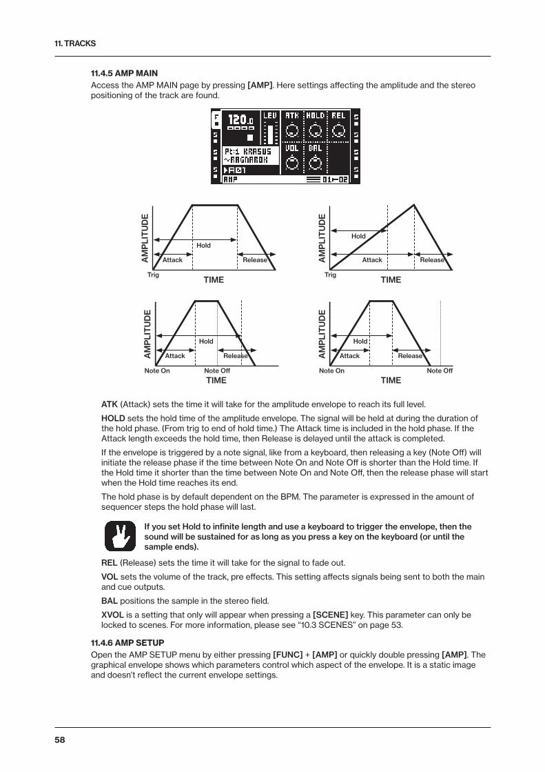
11. TRACKS
58
11.4.5 AMP MAINAccess the AMP MAIN page by pressing [AMP]. Here settings affecting the amplitude and the stereo positioning of the track are found.
TIME
AM
PLI
TU
DE
Trig
Attack Release
Hold
TIME
AM
PLI
TU
DE
Trig
Attack Release
Hold
TIME
AM
PLI
TU
DE
Note On
Attack Release
Hold
Note Off
TIME
AM
PLI
TU
DE
Note On
Attack Release
Hold
Note Off
ATK (Attack) sets the time it will take for the amplitude envelope to reach its full level.
HOLD sets the hold time of the amplitude envelope. The signal will be held at during the duration of the hold phase. (From trig to end of hold time.) The Attack time is included in the hold phase. If the Attack length exceeds the hold time, then Release is delayed until the attack is completed.
If the envelope is triggered by a note signal, like from a keyboard, then releasing a key (Note Off) will initiate the release phase if the time between Note On and Note Off is shorter than the Hold time. If the Hold time it shorter than the time between Note On and Note Off, then the release phase will start when the Hold time reaches its end.
The hold phase is by default dependent on the BPM. The parameter is expressed in the amount of sequencer steps the hold phase will last.
If you set Hold to infinite length and use a keyboard to trigger the envelope, then the sound will be sustained for as long as you press a key on the keyboard (or until the sample ends).
REL (Release) sets the time it will take for the signal to fade out.
VOL sets the volume of the track, pre effects. This setting affects signals being sent to both the main and cue outputs.
BAL positions the sample in the stereo field.
XVOL is a setting that only will appear when pressing a [SCENE] key. This parameter can only be locked to scenes. For more information, please see “10.3 SCENES” on page 53.
11.4.6 AMP SETUPOpen the AMP SETUP menu by either pressing [FUNC] + [AMP] or quickly double pressing [AMP]. The graphical envelope shows which parameters control which aspect of the envelope. It is a static image and doesn’t reflect the current envelope settings.
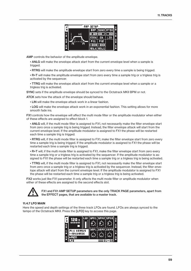
11. TRACKS
59
AMP controls the behavior of the amplitude envelope.
• ANLG will make the envelope attack start from the current envelope level when a sample is trigged.
• RTRG will make the amplitude envelope start from zero every time a sample is being trigged.
• R+T will make the amplitude envelope start from zero every time a sample trig or a trigless trig is activated by the sequencer.
• TTRG will make the envelope attack start from the current envelope level when a sample or a trigless trig is activated.
SYNC sets if the amplitude envelope should be synced to the Octatrack MKII BPM or not.
ATCK sets how the attack of the envelope should behave.
• LIN will make the envelope attack work in a linear fashion.
• LOG will make the envelope attack work in an exponential fashion. This setting allows for more smooth fade ins.
FX1 controls how the envelope will affect the multi mode filter or the amplitude modulator when either of these effects are assigned to effect block 1.
• ANLG will, if the multi mode filter is assigned to FX1, not necessarily make the filter envelope start from zero once a sample trig is being trigged. Instead, the filter envelope attack will start from the current envelope level. If the amplitude modulator is assigned to FX1 the phase will be restarted each time a sample trig is trigged.
• RTRG will, if the multi mode filter is assigned to FX1, make the filter envelope start from zero every time a sample trig is being trigged. If the amplitude modulator is assigned to FX1 the phase will be restarted each time a sample trig is trigged.
• R+T will, if the multi mode filter is assigned to FX1, make the filter envelope start from zero every time a sample trig or a trigless trig is activated by the sequencer. If the amplitude modulator is as-signed to FX1 the phase will be restarted each time a sample trig or a trigless trig is being activated.
• TTRG will, if the multi mode filter is assigned to FX1, not necessarily make the filter envelope start from zero once a sample trig or a trigless trig is activated by the sequencer. Instead, the filter enve-lope attack will start from the current envelope level. If the amplitude modulator is assigned to FX1 the phase will be restarted each time a sample trig or a trigless trig is being activated.
FX2 works just like FX1 parameter. It only affects the multi mode filter or amplitude modulator when either of these effects are assigned to the second effects slot.
FX1 and FX1 AMP SETUP parameters are the only TRACK PAGE parameters, apart from the EFFECT pages, that are available to a master track.
11.4.7 LFO MAINHere the speed and depth settings of the three track LFOs are found. LFOs are always synced to the tempo of the Octatrack MKII. Press the [LFO] key to access this page.
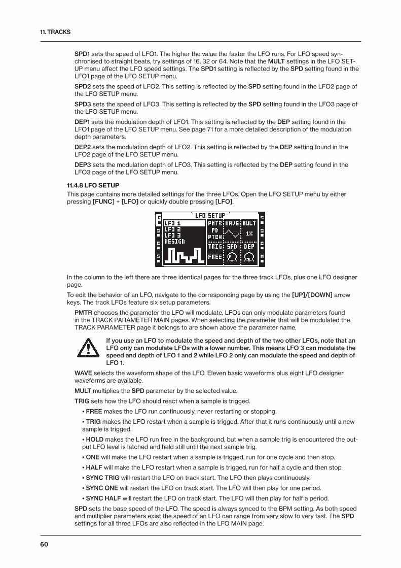
11. TRACKS
60
SPD1 sets the speed of LFO1. The higher the value the faster the LFO runs. For LFO speed syn-chronised to straight beats, try settings of 16, 32 or 64. Note that the MULT settings in the LFO SET-UP menu affect the LFO speed settings. The SPD1 setting is reflected by the SPD setting found in the LFO1 page of the LFO SETUP menu.
SPD2 sets the speed of LFO2. This setting is reflected by the SPD setting found in the LFO2 page of the LFO SETUP menu.
SPD3 sets the speed of LFO3. This setting is reflected by the SPD setting found in the LFO3 page of the LFO SETUP menu.
DEP1 sets the modulation depth of LFO1. This setting is reflected by the DEP setting found in the LFO1 page of the LFO SETUP menu. See page 71 for a more detailed description of the modulation depth parameters.
DEP2 sets the modulation depth of LFO2. This setting is reflected by the DEP setting found in the LFO2 page of the LFO SETUP menu.
DEP3 sets the modulation depth of LFO3. This setting is reflected by the DEP setting found in the LFO3 page of the LFO SETUP menu.
11.4.8 LFO SETUPThis page contains more detailed settings for the three LFOs. Open the LFO SETUP menu by either pressing [FUNC] + [LFO] or quickly double pressing [LFO].
In the column to the left there are three identical pages for the three track LFOs, plus one LFO designer page.
To edit the behavior of an LFO, navigate to the corresponding page by using the [UP]/[DOWN] arrow keys. The track LFOs feature six setup parameters.
PMTR chooses the parameter the LFO will modulate. LFOs can only modulate parameters found in the TRACK PARAMETER MAIN pages. When selecting the parameter that will be modulated the TRACK PARAMETER page it belongs to are shown above the parameter name.
If you use an LFO to modulate the speed and depth of the two other LFOs, note that an LFO only can modulate LFOs with a lower number. This means LFO 3 can modulate the speed and depth of LFO 1 and 2 while LFO 2 only can modulate the speed and depth of LFO 1.
WAVE selects the waveform shape of the LFO. Eleven basic waveforms plus eight LFO designer waveforms are available.
MULT multiplies the SPD parameter by the selected value.
TRIG sets how the LFO should react when a sample is trigged.
• FREE makes the LFO run continuously, never restarting or stopping.
• TRIG makes the LFO restart when a sample is trigged. After that it runs continuously until a new sample is trigged.
• HOLD makes the LFO run free in the background, but when a sample trig is encountered the out-put LFO level is latched and held still until the next sample trig.
• ONE will make the LFO restart when a sample is trigged, run for one cycle and then stop.
• HALF will make the LFO restart when a sample is trigged, run for half a cycle and then stop.
• SYNC TRIG will restart the LFO on track start. The LFO then plays continuously.
• SYNC ONE will restart the LFO on track start. The LFO will then play for one period.
• SYNC HALF will restart the LFO on track start. The LFO will then play for half a period.
SPD sets the base speed of the LFO. The speed is always synced to the BPM setting. As both speed and multiplier parameters exist the speed of an LFO can range from very slow to very fast. The SPD settings for all three LFOs are also reflected in the LFO MAIN page.
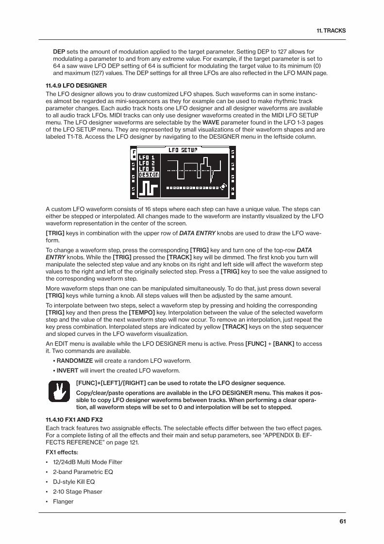
11. TRACKS
61
DEP sets the amount of modulation applied to the target parameter. Setting DEP to 127 allows for modulating a parameter to and from any extreme value. For example, if the target parameter is set to 64 a saw wave LFO DEP setting of 64 is sufficient for modulating the target value to its minimum (0) and maximum (127) values. The DEP settings for all three LFOs are also reflected in the LFO MAIN page.
11.4.9 LFO DESIGNERThe LFO designer allows you to draw customized LFO shapes. Such waveforms can in some instanc-es almost be regarded as mini-sequencers as they for example can be used to make rhythmic track parameter changes. Each audio track hosts one LFO designer and all designer waveforms are available to all audio track LFOs. MIDI tracks can only use designer waveforms created in the MIDI LFO SETUP menu. The LFO designer waveforms are selectable by the WAVE parameter found in the LFO 1-3 pages of the LFO SETUP menu. They are represented by small visualizations of their waveform shapes and are labeled T1-T8. Access the LFO designer by navigating to the DESIGNER menu in the leftside column.
A custom LFO waveform consists of 16 steps where each step can have a unique value. The steps can either be stepped or interpolated. All changes made to the waveform are instantly visualized by the LFO waveform representation in the center of the screen.
[TRIG] keys in combination with the upper row of DATA ENTRY knobs are used to draw the LFO wave-form.
To change a waveform step, press the corresponding [TRIG] key and turn one of the top-row DATA ENTRY knobs. While the [TRIG] pressed the [TRACK] key will be dimmed. The first knob you turn will manipulate the selected step value and any knobs on its right and left side will affect the waveform step values to the right and left of the originally selected step. Press a [TRIG] key to see the value assigned to the corresponding waveform step.
More waveform steps than one can be manipulated simultaneously. To do that, just press down several [TRIG] keys while turning a knob. All steps values will then be adjusted by the same amount.
To interpolate between two steps, select a waveform step by pressing and holding the corresponding [TRIG] key and then press the [TEMPO] key. Interpolation between the value of the selected waveform step and the value of the next waveform step will now occur. To remove an interpolation, just repeat the key press combination. Interpolated steps are indicated by yellow [TRACK] keys on the step sequencer and sloped curves in the LFO waveform visualization.
An EDIT menu is available while the LFO DESIGNER menu is active. Press [FUNC] + [BANK] to access it. Two commands are available.
• RANDOMIZE will create a random LFO waveform.
• INVERT will invert the created LFO waveform.
[FUNC]+[LEFT]/[RIGHT] can be used to rotate the LFO designer sequence.
Copy/clear/paste operations are available in the LFO DESIGNER menu. This makes it pos-sible to copy LFO designer waveforms between tracks. When performing a clear opera-tion, all waveform steps will be set to 0 and interpolation will be set to stepped.
11.4.10 FX1 AND FX2Each track features two assignable effects. The selectable effects differ between the two effect pages. For a complete listing of all the effects and their main and setup parameters, see “APPENDIX B: EF-FECTS REFERENCE” on page 121.
FX1 effects:
• 12/24dB Multi Mode Filter
• 2-band Parametric EQ
• DJ-style Kill EQ
• 2-10 Stage Phaser
• Flanger
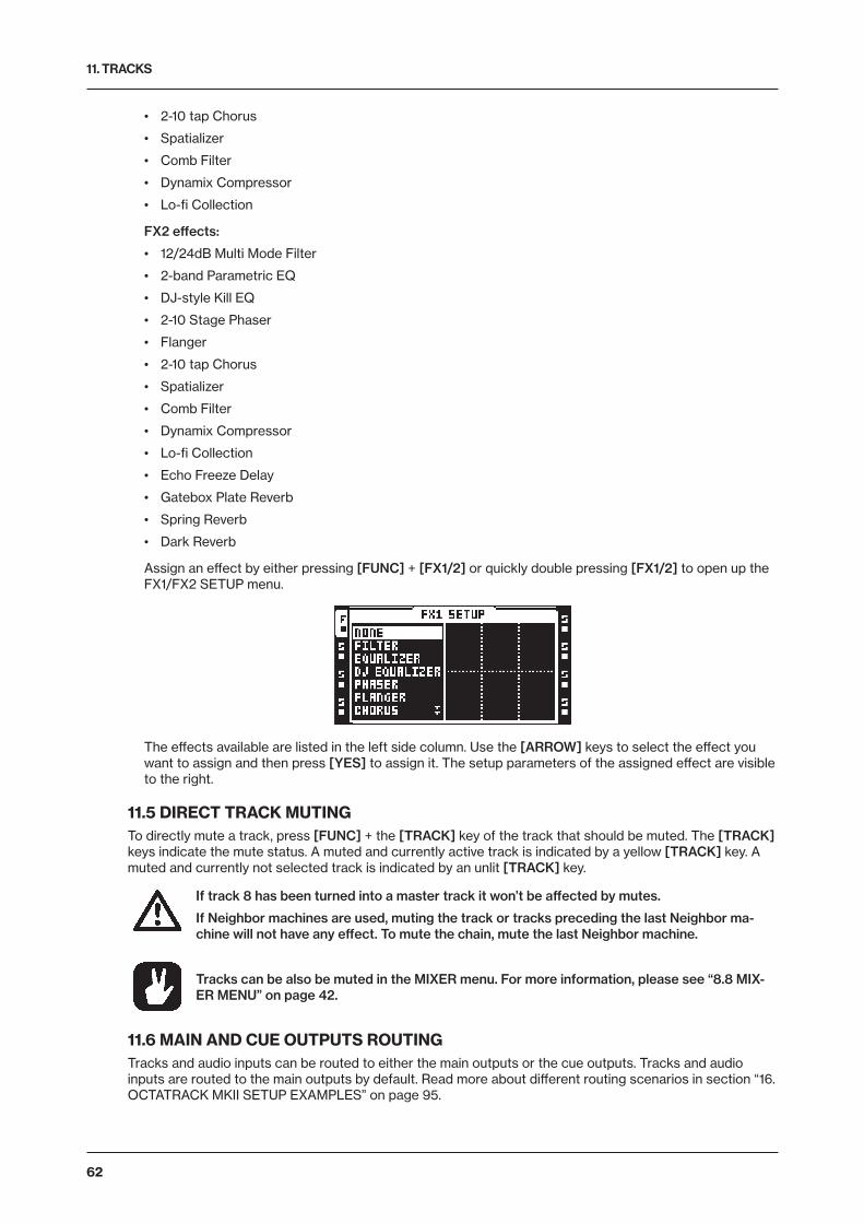
11. TRACKS
62
• 2-10 tap Chorus
• Spatializer
• Comb Filter
• Dynamix Compressor
• Lo-fi Collection
FX2 effects:
• 12/24dB Multi Mode Filter
• 2-band Parametric EQ
• DJ-style Kill EQ
• 2-10 Stage Phaser
• Flanger
• 2-10 tap Chorus
• Spatializer
• Comb Filter
• Dynamix Compressor
• Lo-fi Collection
• Echo Freeze Delay
• Gatebox Plate Reverb
• Spring Reverb
• Dark Reverb
Assign an effect by either pressing [FUNC] + [FX1/2] or quickly double pressing [FX1/2] to open up the FX1/FX2 SETUP menu.
The effects available are listed in the left side column. Use the [ARROW] keys to select the effect you want to assign and then press [YES] to assign it. The setup parameters of the assigned effect are visible to the right.
11.5 DIRECT TRACK MUTINGTo directly mute a track, press [FUNC] + the [TRACK] key of the track that should be muted. The [TRACK] keys indicate the mute status. A muted and currently active track is indicated by a yellow [TRACK] key. A muted and currently not selected track is indicated by an unlit [TRACK] key.
If track 8 has been turned into a master track it won’t be affected by mutes.
If Neighbor machines are used, muting the track or tracks preceding the last Neighbor ma-chine will not have any effect. To mute the chain, mute the last Neighbor machine.
Tracks can be also be muted in the MIXER menu. For more information, please see “8.8 MIX-ER MENU” on page 42.
11.6 MAIN AND CUE OUTPUTS ROUTINGTracks and audio inputs can be routed to either the main outputs or the cue outputs. Tracks and audio inputs are routed to the main outputs by default. Read more about different routing scenarios in section “16. OCTATRACK MKII SETUP EXAMPLES” on page 95.
11. TRACKS
63
11.6.1 MAIN OUTPUT ROUTINGThis is the default setting. All tracks and inputs are routed to the main outputs.
11.6.2 CUE OUTPUT ROUTINGPressing [CUE] + [TRACK] will route the selected track to the cue outputs. A cued track will still be au-dible from the main outputs. When a track is cued the [TRACK] key will flash. Note that cue output is not available on track 8 if it is set to be the master track. By pressing [CUE] + the [REC1/2/3] keys it is also possible to route the audio inputs to the cue outputs. Cued inputs are indicated by alternating <REC> LEDs.
11.6.3 PARAMETERS AFFECTING MAIN AND CUE LEVELSDifferent parameters affect the volume of the track or inputs depending on how they are being routed.
TRACK MAIN LEVEL is set by the LEVEL knob. It will affect the post effects signal of the track when it is being routed to the main outputs. It will not affect the cue level of a cued track. The screen shows a graphic indicator of the level (and its numerical value while the knob is being turned).
TRACK CUE LEVEL is set by pressing and holding [CUE] while turning the LEVEL knob. It will affect the post effects signal of the track when it is being routed to the cue outputs. It will not affect the main level of a track. The cue level has a separate graphic level indicator which is shown instead of the main level indicator while [CUE] is pressed. This is not applicable to track 8, if it has been set to be the master track, in which case the cue output is unavailable and the level graphic indicator will be shown in gray.
VOL is found in the AMP MAIN menu of the track. It will affect the pre effects signal of a track, regard-less of the track being routed to the main or cue outputs.
DIR is found in the MIXER menu. It affects the signal of incoming audio routed to the main outputs. It doesn’t affect the cue level when the audio inputs are cued. When cueing the audio inputs, the cue level will be an equivalent of a DIR setting of 100.
By enabling the STUDIO mode, the default main and cue output routing behavior can be changed. STUDIO mode is handy when wanting to use the cue outputs as a pair of assign-able outputs. For more information, please see “8.6.1 AUDIO” on page 35.
If a cued track is muted it will only be audible from the cue outputs.
When the CUE MUTES TRACK setting, found in the PERSONALIZE menu, is activated a track being cued will be muted at the same. Read more in the section “8.5 SYSTEM” on page 32.
The XLV, XVOL and XDIR parameters are available exclusively to scenes. They are useful for avoiding dips in volume when doing fades between tracks or inputs. Read more about these parameters in the section “10.3.2 SCENE VOLUME LOCKING” on page 54.
The MIX parameter in the MIXER menu sets how much of the main and cue signals that should be sent to the headphones output. Read more about the parameter in the section “8.8 MIXER MENU” on page 42.
12. PATTERNS
64
12. PATTERNSThe sequencer of the Octatrack MKII is incredibly powerful and plays an extremely important role in pro-cessing sounds and samples.
The sequencer stores information in patterns. Patterns consist of information about how the eight audio tracks and eight MIDI tracks should be played back. All adjustments made to patterns are automatically saved. If you wish to alter a pattern but keep the initial sample trig placements you will have to copy the pat-tern to a new location and then use the copied pattern as the basis for the new pattern. A pattern contains:
• Sample trigs for the eight audio tracks.
• Note trigs for the eight MIDI tracks.
• Track recorder trigs for the eight track recorders.
• Trigless trigs for the eight audio tracks and the eight MIDI tracks.
• Swing trigs for the eight audio tracks and the eight MIDI tracks.
• Slide trigs for the eight audio tracks.
• One shot trigs for the eight audio tracks.
• Information about which pattern is linked to a part.
• Parameter locks.
• Conditional locks
• Sample locks.
• Length and time signature of the tracks.
12.1 TRIG INDICATIONSDepending on if the [RECORD] key is lit or not, the [TRIG] keys will display different information when the sequencer is playing.
If the [RECORD] key is unlit the eight rightmost [TRIG] keys will indicate sample trigs being activated by the sequencer. [TRIG] key 9 acts as an indicator for track 1, [TRIG] key 10 acts as an indicator for track 2 and so on.
If the [RECORD] key is lit the various trigs of the active track will be shown.
12.2 BASIC PATTERN OPERATIONSThe Octatrack MKII can switch between patterns without any audible lag. This, plus the ability to chain patterns, are handy features when for example making live improvisations.
12.2.1 SELECTING A PATTERNEach project hosts 16 banks each containing 16 patterns. Banks and patterns are selected using the [BANK] and [PTN] keys in combination with the 16 [TRIG] keys.
Patterns can be selected from the currently active bank or from one of the other banks. Press the [PTN] key in combination with one of the [TRIG 1–16] keys to select a pattern located in the currently active bank. Patterns containing data are indicated by green [TRIG] keys. The currently active pattern is indi-cated by a red [TRIG] key.
Select a pattern from another bank by first selecting the bank by using the [BANK] + [TRIG 1–16] keys. After the “CHOOSE PATTERN” prompt appears, press one of the [TRIG] keys to select a pattern located in the chosen bank.
12.2.2 PATTERN CONTROLPressing [PLAY] will start the playback of a pattern. Pressing [STOP] will stop the playback of all tracks, except tracks containing Thru machines. The sound will be cut off, but effects like the Echo Freeze Delay will continue to be audible until the delay repeats have faded out. Press [STOP] + [STOP] to stop playback of all tracks, kill the Echo Freeze Delay and send out an all notes off MIDI command on all MIDI tracks. After a pattern has been stopped, pressing [PLAY] will make the pattern start playing from the beginning.
If you press [PLAY] when a pattern is playing, the playback will be paused. Press [PLAY] again to resume the playback.
12.2.3 PATTERN CHAININGYou can use pattern chaining to loop a sequence of patterns. It is only possible to chain patterns located
12. PATTERNS
65
in the same bank, and a chain can not contain the same pattern twice. Chain patterns by pressing and holding the [PTN] key and then press and hold the [TRIG] keys in the same order as you want the chained patterns to play. Chaining is indicated by a double arrow between the current pattern and the pattern that will play next. Several patterns can be chained.
Pressing [STOP] while a pattern chain is playing will stop playback and reset the pattern chain. Next time [PLAY] is pressed the pattern chain will start playing from the beginning. If [STOP] has been pressed, pressing [STOP] again will unlink all patterns in the chain.
12.3 RECORDING MODESThe Octatrack MKII offers two main modes of inputting trigs when creating a pattern, GRID RECORDING mode and LIVE RECORDING mode.
12.3.1 GRID RECORDING MODEGRID RECORDING is a method of composing where trigs are added by using the 16 [TRIG] keys. In the default state, the 16 [TRIG] keys represent 1 bar of 16th notes. This is however dependent on the SCALE SETUP settings.
Enter GRID RECORDING mode by pressing the [RECORD] key. A lit red [RECORD] key indicates GRID RECORDING mode is active. Select the track to which you want to add trigs by pressing the relevant [TRACK] key. Place for example sample trigs on the sequencer by pressing the [TRIG] keys. Sample trigs are indicated by red [TRIG] keys. Several trig variants exist and they are covered in section “12.4 TRIG TYPES” on page 66.
If the pattern contains more than 16 steps, switch to the pattern page you want to edit by pressing the [PAGE] key. The active pattern page is being indicated by a fully lit <PAGE> LED.
Press [PLAY] to listen to the sequence. You can input sample trigs when the sequencer is playing as well.
All trigs of a track can be shifted forwards or backwards on the sequencer. While in GRID RECORDING mode, hold down [FUNC] while pressing the [LEFT] or [RIGHT] arrow keys to perform the trig shift.
12.3.2 LIVE RECORDING MODELIVE RECORDING mode is the second method of adding trigs to the tracks. In this recording mode, the [TRIG] keys can be played in real time to input trigs. It is also possible to enter parameter locks in real time. Trigs input in LIVE RECORDING mode will by default be quantized to full sequencer steps, hence not micro timed. This behavior can be changed in the PERSONALIZE menu. For more information, please see “8.5.4 PERSONALIZE” on page 33.
Hold [RECORD] while pressing [PLAY] to enter LIVE RECORDING mode. The sequencer will start to play and the [RECORD] key will start to flash. You can now enter sample trigs in real time by pressing [TRIG] keys 9-16. Pressing [TRIG] key 9 will input a sample trig on track 1, pressing [TRIG] key 10 will input a sample trig on track 2 and so on. When in TRACKS mode or CHROMATIC mode, trigless trigs, instead of sample trigs, can be recorded if [FUNC] is held while pressing the [TRIG] keys. This is useful if you, for instance, want to use the CHROMATIC mode to live record pitch changes to a sample, but don’t want the sample to restart on every pitch change. Read more about the TRACKS and CHROMATIC trig modes in the section “12.7 TRIG MODES” on page 68.
Turning a knob while in LIVE RECORDING mode will input parameter locks to the active track. The pa-rameter locks will be input as lock trigs when no sample trigs are present. Sample trigs will be parameter locked accordingly.
To erase trigs in real time, press and hold [NO] + the [TRACK] key of the track you wish to erase trigs from. All trigs hit by the light of the running sequencer will be erased from the active track. The trigs of more than one track can be removed by pressing several [TRACK] keys simultaneously.
To remove only parameter locks in real time, press and hold [FUNC] + [NO]. All trigs hit by the running light of the sequencer will be erased from the active track. Sample locks will however not be erased.
Remove sample locks in real time by pressing [NO] while pressing the LEVEL knob.
Remove specific parameter locks in real time by pressing [NO] while pressing the DATA ENTRY knob corresponding to the parameter that should be removed.
To stop both the recording and the playback of the sequencer, press [STOP]. To exit LIVE RECORDING mode and keep the sequencer playing the pattern, press [PLAY].
12. PATTERNS
66
12.4 TRIG TYPESA trig is a sequencer event that you can place when you want the sequencer to perform an action. The Octatrack MKII sequencer accommodates a number of different trig types. Trigs can be entered while being in GRID or LIVE RECORDING mode and are, depending on the type of trig, indicated by red, green or yellow [TRIG] keys colors.
12.4.1 SAMPLE TRIGSSample trigs trig the machine of the track, making the sample assigned to the machine play. Enter by simply pressing a [TRIG] key. Sample trigs are indicated by red [TRIG] keys.
12.4.2 NOTE TRIGSNote trigs trig notes on the MIDI tracks. Enter by simply pressing a [TRIG] key. Note trigs are indicated by red [TRIG] keys.
12.4.3 LOCK TRIGSLock trigs trigger parameter locks, but without triggering samples/notes. Lock trigs do not trig machines, LFOs or FX envelopes. Enter them by pressing [FUNC] + [TRIG].
Lock trigs are indicated by green [TRIG] keys. Already existing sample trigs can be turned to lock trigs by pressing [TRIG] + [NO] twice. To turn a lock trig to a trigless trig, press [TRIG] + [YES]. When press-ing the [TRIG] key of a lock trig, it will turn into a sample trig. Press the [TRIG] key again to remove the sample trig altogether.
When in LIVE RECORDING mode and changing lockable parameters, lock trigs containing the locked parameters is added automatically to the sequencer.
12.4.4 TRIGLESS TRIGSTrigless trigs function similarly to lock trigs, but trig LFOs and FX envelopes. They can only be applied by converting sample trigs or lock trigs.
Trigless trigs are indicated by green full-bright [TRIG] keys. An already existing sample trig can be turned to a trigless trig by pressing [TRIG] + [NO]. To turn a lock trig to a trigless trig, press [TRIG] + [YES]. When pressing the [TRIG] key of a trigless trig, it will turn into a sample trig. Press the [TRIG] key again to remove the sample trig altogether.
12.4.5 ONE SHOT TRIGSOne shot trigs trig a sample or a track recorder only once. They are especially useful when using the Oc-tatrack MKII as a backing track machine, as they, for example, can trig very long Static samples without retrigging them once the pattern loops. This trig type is also available to recorder trigs. One shot trigs are not available to MIDI tracks.
If a track contains several one shot trigs, all one shot trigs of that track will be disarmed once one of the one shot trigs has been activated by the sequencer. This extends to the tracks of other patterns as well. If a one shot trig has been trigged on track 1 of pattern A01, any one shot trigs on the first track of patterns A02-P16 will also be disarmed.
One shot trigs are entered by pressing [FUNC] + the [TRIG] key of an existing sample trig. The [TRIG] key will change from red to yellow, indicating the trig now is now a one shot trig. One shot trigs that have been activated by the sequencer are indicated by alternating yellow and red [TRIG] keys. Quickly press-ing [STOP] + [STOP] while the sequencer is stopped, power cycling the Octatrack MKII or changing projects will re-arm all one shot trigs. The [STOP] + [STOP] behavior can be disabled in the PERSONAL-IZE menu. For more information, please see “8.5.4 PERSONALIZE” on page 33.
There exists several ways of arming and disarming one shot trigs. While in GRID RECORDING mode and either the RECORDING SETUP menus or the TRACK TRIG EDIT menu with REC TRIG chosen, is active, all one shot recorder trigs of the active track will be re-armed when pressing [YES]. The text “ARM REC TRK” will be visible. The one shot recorder trigs will keep re-arming for as long as the key is held. Note that one shot sample trigs will not be affected. This way of arming and disarming can be disabled in the PERSONALIZE menu. For more information, please see “8.5.4 PERSONALIZE” on page 33.
Pressing [TRACK] + [YES] will also re-arm a tracks all one shot recorder trigs. The one shot recorder trigs will keep re-arming for as long as the key combination is held. Pressing [TRACK] + [NO] will disarm all one shot recorder trigs of a track. These operations can be performed even if GRID RECORDING mode is not active. Neither the RECORDING SETUP menus nor the TRACK TRIG EDIT menu have to be open.
While in GRID RECORDING mode and no particular menu is open, all one shot sample trigs of the active track will be re-armed when pressing either [YES] or [FUNC] + [YES]. The text “ARM TRK” will be visi-ble. Pressing either [NO] or [FUNC] + [NO] will disarm one shot sample trigs of the active track. The text “DISARM TRK” will be visible. Note that one shot recorder trigs will not be affected. Arming and disarm-
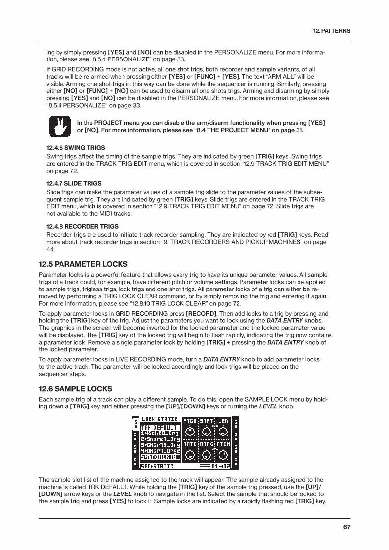
12. PATTERNS
67
ing by simply pressing [YES] and [NO] can be disabled in the PERSONALIZE menu. For more informa-tion, please see “8.5.4 PERSONALIZE” on page 33.
If GRID RECORDING mode is not active, all one shot trigs, both recorder and sample variants, of all tracks will be re-armed when pressing either [YES] or [FUNC] + [YES]. The text “ARM ALL” will be visible. Arming one shot trigs in this way can be done while the sequencer is running. Similarly, pressing either [NO] or [FUNC] + [NO] can be used to disarm all one shots trigs. Arming and disarming by simply pressing [YES] and [NO] can be disabled in the PERSONALIZE menu. For more information, please see “8.5.4 PERSONALIZE” on page 33.
In the PROJECT menu you can disable the arm/disarm functionality when pressing [YES] or [NO]. For more information, please see “8.4 THE PROJECT MENU” on page 31.
12.4.6 SWING TRIGSSwing trigs affect the timing of the sample trigs. They are indicated by green [TRIG] keys. Swing trigs are entered in the TRACK TRIG EDIT menu, which is covered in section “12.9 TRACK TRIG EDIT MENU” on page 72.
12.4.7 SLIDE TRIGSSlide trigs can make the parameter values of a sample trig slide to the parameter values of the subse-quent sample trig. They are indicated by green [TRIG] keys. Slide trigs are entered in the TRACK TRIG EDIT menu, which is covered in section “12.9 TRACK TRIG EDIT MENU” on page 72. Slide trigs are not available to the MIDI tracks.
12.4.8 RECORDER TRIGSRecorder trigs are used to initiate track recorder sampling. They are indicated by red [TRIG] keys. Read more about track recorder trigs in section “9. TRACK RECORDERS AND PICKUP MACHINES” on page 44.
12.5 PARAMETER LOCKSParameter locks is a powerful feature that allows every trig to have its unique parameter values. All sample trigs of a track could, for example, have different pitch or volume settings. Parameter locks can be applied to sample trigs, trigless trigs, lock trigs and one shot trigs. All parameter locks of a trig can either be re-moved by performing a TRIG LOCK CLEAR command, or by simply removing the trig and entering it again. For more information, please see “12.8.10 TRIG LOCK CLEAR” on page 72.
To apply parameter locks in GRID RECORDING press [RECORD]. Then add locks to a trig by pressing and holding the [TRIG] key of the trig. Adjust the parameters you want to lock using the DATA ENTRY knobs. The graphics in the screen will become inverted for the locked parameter and the locked parameter value will be displayed. The [TRIG] key of the locked trig will begin to flash rapidly, indicating the trig now contains a parameter lock. Remove a single parameter lock by holding [TRIG] + pressing the DATA ENTRY knob of the locked parameter.
To apply parameter locks in LIVE RECORDING mode, turn a DATA ENTRY knob to add parameter locks to the active track. The parameter will be locked accordingly and lock trigs will be placed on the sequencer steps.
12.6 SAMPLE LOCKSEach sample trig of a track can play a different sample. To do this, open the SAMPLE LOCK menu by hold-ing down a [TRIG] key and either pressing the [UP]/[DOWN] keys or turning the LEVEL knob.
The sample slot list of the machine assigned to the track will appear. The sample already assigned to the machine is called TRK DEFAULT. While holding the [TRIG] key of the sample trig pressed, use the [UP]/[DOWN] arrow keys or the LEVEL knob to navigate in the list. Select the sample that should be locked to the sample trig and press [YES] to lock it. Sample locks are indicated by a rapidly flashing red [TRIG] key.
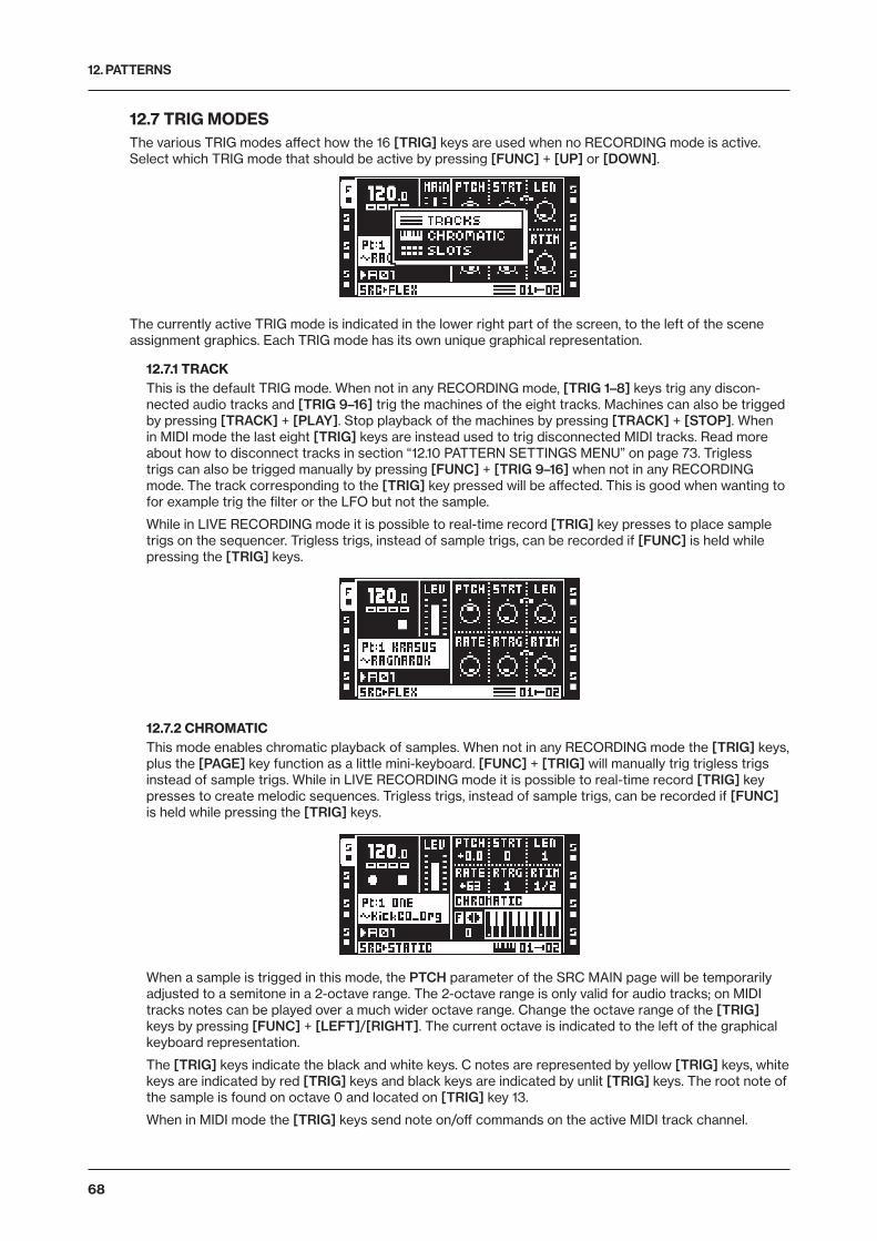
12. PATTERNS
68
12.7 TRIG MODESThe various TRIG modes affect how the 16 [TRIG] keys are used when no RECORDING mode is active. Select which TRIG mode that should be active by pressing [FUNC] + [UP] or [DOWN].
The currently active TRIG mode is indicated in the lower right part of the screen, to the left of the scene assignment graphics. Each TRIG mode has its own unique graphical representation.
12.7.1 TRACKThis is the default TRIG mode. When not in any RECORDING mode, [TRIG 1–8] keys trig any discon-nected audio tracks and [TRIG 9–16] trig the machines of the eight tracks. Machines can also be trigged by pressing [TRACK] + [PLAY]. Stop playback of the machines by pressing [TRACK] + [STOP]. When in MIDI mode the last eight [TRIG] keys are instead used to trig disconnected MIDI tracks. Read more about how to disconnect tracks in section “12.10 PATTERN SETTINGS MENU” on page 73. Trigless trigs can also be trigged manually by pressing [FUNC] + [TRIG 9–16] when not in any RECORDING mode. The track corresponding to the [TRIG] key pressed will be affected. This is good when wanting to for example trig the filter or the LFO but not the sample.
While in LIVE RECORDING mode it is possible to real-time record [TRIG] key presses to place sample trigs on the sequencer. Trigless trigs, instead of sample trigs, can be recorded if [FUNC] is held while pressing the [TRIG] keys.
12.7.2 CHROMATICThis mode enables chromatic playback of samples. When not in any RECORDING mode the [TRIG] keys, plus the [PAGE] key function as a little mini-keyboard. [FUNC] + [TRIG] will manually trig trigless trigs instead of sample trigs. While in LIVE RECORDING mode it is possible to real-time record [TRIG] key presses to create melodic sequences. Trigless trigs, instead of sample trigs, can be recorded if [FUNC] is held while pressing the [TRIG] keys.
When a sample is trigged in this mode, the PTCH parameter of the SRC MAIN page will be temporarily adjusted to a semitone in a 2-octave range. The 2-octave range is only valid for audio tracks; on MIDI tracks notes can be played over a much wider octave range. Change the octave range of the [TRIG] keys by pressing [FUNC] + [LEFT]/[RIGHT]. The current octave is indicated to the left of the graphical keyboard representation.
The [TRIG] keys indicate the black and white keys. C notes are represented by yellow [TRIG] keys, white keys are indicated by red [TRIG] keys and black keys are indicated by unlit [TRIG] keys. The root note of the sample is found on octave 0 and located on [TRIG] key 13.
When in MIDI mode the [TRIG] keys send note on/off commands on the active MIDI track channel.
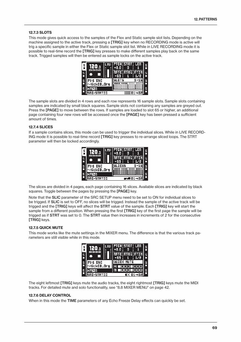
12. PATTERNS
69
12.7.3 SLOTSThis mode gives quick access to the samples of the Flex and Static sample slot lists. Depending on the machine assigned to the active track, pressing a [TRIG] key when no RECORDING mode is active will trig a specific sample in either the Flex or Static sample slot list. While in LIVE RECORDING mode it is possible to real-time record the [TRIG] key presses to make different samples play back on the same track. Trigged samples will then be entered as sample locks on the active track.
The sample slots are divided in 4 rows and each row represents 16 sample slots. Sample slots containing samples are indicated by small black squares. Sample slots not containing any samples are greyed out. Press the [PAGE] to move between the rows. If samples are loaded to slot 65 or higher, an additional page containing four new rows will be accessed once the [PAGE] key has been pressed a sufficient amount of times.
12.7.4 SLICESIf a sample contains slices, this mode can be used to trigger the individual slices. While in LIVE RECORD-ING mode it is possible to real-time record [TRIG] key presses to re-arrange sliced loops. The STRT parameter will then be locked accordingly.
The slices are divided in 4 pages, each page containing 16 slices. Available slices are indicated by black squares. Toggle between the pages by pressing the [PAGE] key.
Note that the SLIC parameter of the SRC SETUP menu need to be set to ON for individual slices to be trigged. If SLIC is set to OFF, no slices will be trigged. Instead the sample of the active track will be trigged and the [TRIG] keys will affect the STRT value of the sample. Each [TRIG] key will start the sample from a different position. When pressing the first [TRIG] key of the first page the sample will be trigged as if STRT was set to 0. The STRT value then increases in increments of 2 for the consecutive [TRIG] keys.
12.7.5 QUICK MUTEThis mode works like the mute settings in the MIXER menu. The difference is that the various track pa-rameters are still visible while in this mode.
The eight leftmost [TRIG] keys mute the audio tracks, the eight rightmost [TRIG] keys mute the MIDI tracks. For detailed mute and solo functionality, see “8.8 MIXER MENU” on page 42.
12.7.6 DELAY CONTROLWhen in this mode the TIME parameters of any Echo Freeze Delay effects can quickly be set.
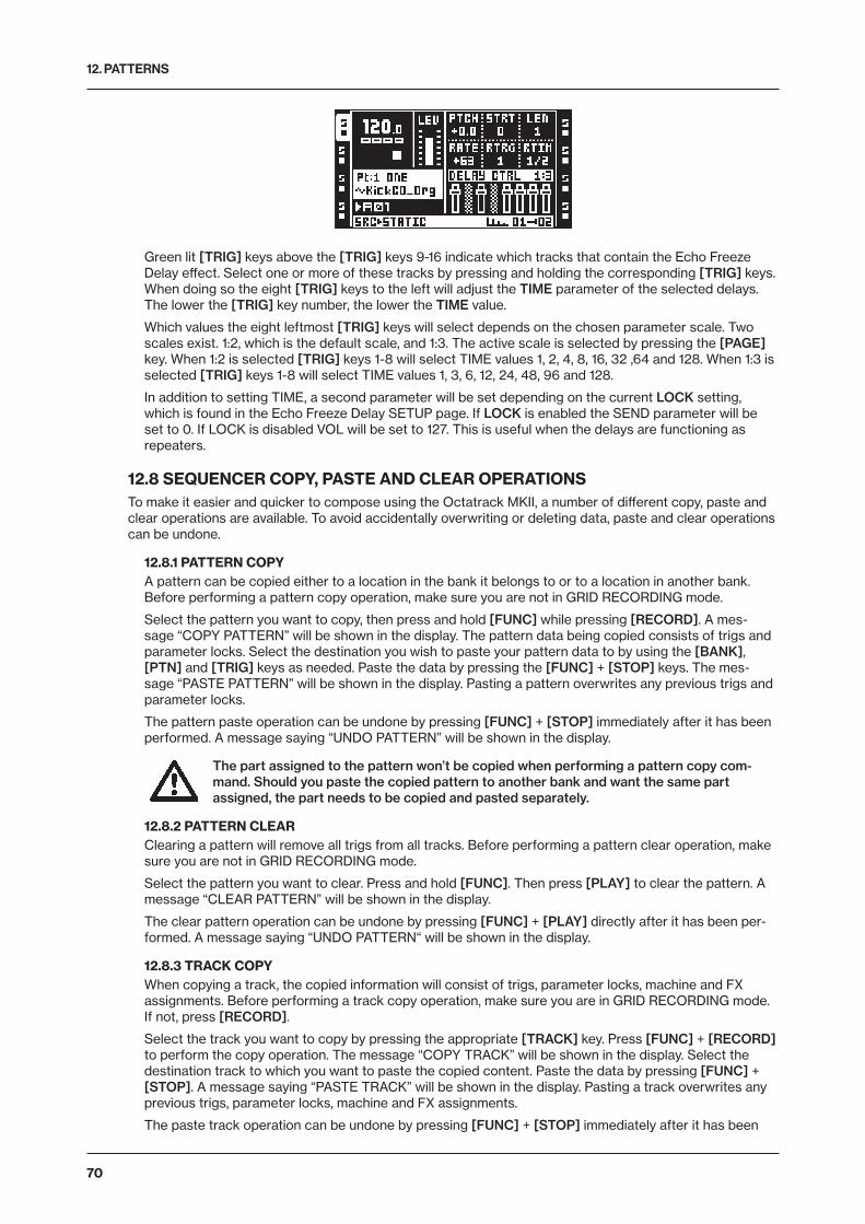
12. PATTERNS
70
Green lit [TRIG] keys above the [TRIG] keys 9-16 indicate which tracks that contain the Echo Freeze Delay effect. Select one or more of these tracks by pressing and holding the corresponding [TRIG] keys. When doing so the eight [TRIG] keys to the left will adjust the TIME parameter of the selected delays. The lower the [TRIG] key number, the lower the TIME value.
Which values the eight leftmost [TRIG] keys will select depends on the chosen parameter scale. Two scales exist. 1:2, which is the default scale, and 1:3. The active scale is selected by pressing the [PAGE] key. When 1:2 is selected [TRIG] keys 1-8 will select TIME values 1, 2, 4, 8, 16, 32 ,64 and 128. When 1:3 is selected [TRIG] keys 1-8 will select TIME values 1, 3, 6, 12, 24, 48, 96 and 128.
In addition to setting TIME, a second parameter will be set depending on the current LOCK setting, which is found in the Echo Freeze Delay SETUP page. If LOCK is enabled the SEND parameter will be set to 0. If LOCK is disabled VOL will be set to 127. This is useful when the delays are functioning as repeaters.
12.8 SEQUENCER COPY, PASTE AND CLEAR OPERATIONSTo make it easier and quicker to compose using the Octatrack MKII, a number of different copy, paste and clear operations are available. To avoid accidentally overwriting or deleting data, paste and clear operations can be undone.
12.8.1 PATTERN COPYA pattern can be copied either to a location in the bank it belongs to or to a location in another bank. Before performing a pattern copy operation, make sure you are not in GRID RECORDING mode.
Select the pattern you want to copy, then press and hold [FUNC] while pressing [RECORD]. A mes-sage “COPY PATTERN” will be shown in the display. The pattern data being copied consists of trigs and parameter locks. Select the destination you wish to paste your pattern data to by using the [BANK], [PTN] and [TRIG] keys as needed. Paste the data by pressing the [FUNC] + [STOP] keys. The mes-sage “PASTE PATTERN” will be shown in the display. Pasting a pattern overwrites any previous trigs and parameter locks.
The pattern paste operation can be undone by pressing [FUNC] + [STOP] immediately after it has been performed. A message saying “UNDO PATTERN” will be shown in the display.
The part assigned to the pattern won’t be copied when performing a pattern copy com-mand. Should you paste the copied pattern to another bank and want the same part assigned, the part needs to be copied and pasted separately.
12.8.2 PATTERN CLEARClearing a pattern will remove all trigs from all tracks. Before performing a pattern clear operation, make sure you are not in GRID RECORDING mode.
Select the pattern you want to clear. Press and hold [FUNC]. Then press [PLAY] to clear the pattern. A message “CLEAR PATTERN” will be shown in the display.
The clear pattern operation can be undone by pressing [FUNC] + [PLAY] directly after it has been per-formed. A message saying “UNDO PATTERN“ will be shown in the display.
12.8.3 TRACK COPYWhen copying a track, the copied information will consist of trigs, parameter locks, machine and FX assignments. Before performing a track copy operation, make sure you are in GRID RECORDING mode. If not, press [RECORD].
Select the track you want to copy by pressing the appropriate [TRACK] key. Press [FUNC] + [RECORD] to perform the copy operation. The message “COPY TRACK” will be shown in the display. Select the destination track to which you want to paste the copied content. Paste the data by pressing [FUNC] + [STOP]. A message saying “PASTE TRACK” will be shown in the display. Pasting a track overwrites any previous trigs, parameter locks, machine and FX assignments.
The paste track operation can be undone by pressing [FUNC] + [STOP] immediately after it has been
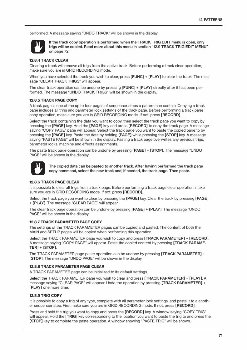
12. PATTERNS
71
performed. A message saying “UNDO TRACK” will be shown in the display.
If the track copy operation is performed when the TRACK TRIG EDIT menu is open, only trigs will be copied. Read more about this menu in section “12.9 TRACK TRIG EDIT MENU” on page 72.
12.8.4 TRACK CLEARClearing a track will remove all trigs from the active track. Before performing a track clear operation, make sure you are in GRID RECORDING mode.
When you have selected the track you wish to clear, press [FUNC] + [PLAY] to clear the track. The mes-sage “CLEAR TRACK TRIGS” will appear.
The clear track operation can be undone by pressing [FUNC] + [PLAY] directly after it has been per-formed. The message “UNDO TRACK TRIGS” will be shown in the display.
12.8.5 TRACK PAGE COPYA track page is one of the up to four pages of sequencer steps a pattern can contain. Copying a track page includes all trigs and parameter lock settings of the track page. Before performing a track page copy operation, make sure you are in GRID RECORDING mode. If not, press [RECORD].
Select the track containing the data you want to copy, then select the track page you want to copy by pressing the [PAGE] key. Hold the [PAGE] key and press [RECORD] to copy the track page. A message saying “COPY PAGE” page will appear. Select the track page you want to paste the copied page to by pressing the [PAGE] key. Paste the data by holding [PAGE] while pressing the [STOP] key. A message saying “PASTE PAGE” will be shown in the display. Pasting a track page overwrites any previous trigs, parameter locks, machine and effects assignments.
The paste track page operation can be undone by pressing [PAGE] + [STOP]. The message “UNDO PAGE” will be shown in the display.
The copied data can be pasted to another track. After having performed the track page copy command, select the new track and, if needed, the track page. Then paste.
12.8.6 TRACK PAGE CLEARIt is possible to clear all trigs from a track page. Before performing a track page clear operation, make sure you are in GRID RECORDING mode. If not, press [RECORD].
Select the track page you want to clear by pressing the [PAGE] key. Clear the track by pressing [PAGE] + [PLAY]. The message “CLEAR PAGE” will appear.
The clear track page operation can be undone by pressing [PAGE] + [PLAY]. The message “UNDO PAGE” will be shown in the display.
12.8.7 TRACK PARAMETER PAGE COPYThe settings of the TRACK PARAMETER pages can be copied and pasted. The content of both the MAIN and SETUP pages will be copied when performing this operation.
Select the TRACK PARAMETER page you wish to copy and press [TRACK PARAMETER] + [RECORD]. A message saying “COPY PAGE” will appear. Paste the copied content by pressing [TRACK PARAME-TER] + [STOP].
The TRACK PARAMETER page paste operation can be undone by pressing [TRACK PARAMETER] + [STOP]. The message “UNDO PAGE” will be shown in the display.
12.8.8 TRACK PARAMETER PAGE CLEARA TRACK PARAMETER page can be initialized to its default settings.
Select the TRACK PARAMETER page you wish to clear and press [TRACK PARAMETER] + [PLAY]. A message saying “CLEAR PAGE” will appear. Undo the operation by pressing [TRACK PARAMETER] + [PLAY] one more time.
12.8.9 TRIG COPYIt is possible to copy a trig of any type, complete with all parameter lock settings, and paste it to a anoth-er sequencer step. First make sure you are in GRID RECORDING mode. If not, press [RECORD].
Press and hold the trig you want to copy and press the [RECORD] key. A window saying “COPY TRIG” will appear. Hold the [TRIG] key corresponding to the location you want to paste the trig to and press the [STOP] key to complete the paste operation. A window showing “PASTE TRIG” will be shown.
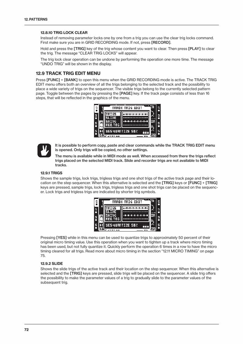
12. PATTERNS
72
12.8.10 TRIG LOCK CLEARInstead of removing parameter locks one by one from a trig you can use the clear trig locks command. First make sure you are in GRID RECORDING mode. If not, press [RECORD].
Hold and press the [TRIG] key of the trig whose content you want to clear. Then press [PLAY] to clear the trig. The message “CLEAR TRIG LOCKS” will appear.
The trig lock clear operation can be undone by performing the operation one more time. The message “UNDO TRIG” will be shown in the display.
12.9 TRACK TRIG EDIT MENUPress [FUNC] + [BANK] to open this menu when the GRID RECORDING mode is active. The TRACK TRIG EDIT menu offers both an overview of all the trigs belonging to the selected track and the possibility to place a wide variety of trigs on the sequencer. The visible trigs belong to the currently selected pattern page. Toggle between the pages by pressing the [PAGE] key. If the track page consists of less than 16 steps, that will be reflected in the graphics of the menu.
It is possible to perform copy, paste and clear commands while the TRACK TRIG EDIT menu is opened. Only trigs will be copied, no other settings.
The menu is available while in MIDI mode as well. When accessed from there the trigs reflect trigs placed on the selected MIDI track. Slide and recorder trigs are not available to MIDI tracks.
12.9.1 TRIGSShows the sample trigs, lock trigs, trigless trigs and one shot trigs of the active track page and their lo-cation on the step sequencer. When this alternative is selected and the [TRIG] keys or [FUNC] + [TRIG] keys are pressed, sample trigs, lock trigs, trigless trigs and one shot trigs can be placed on the sequenc-er. Lock trigs and trigless trigs are indicated by shorter trig symbols.
Pressing [YES] while in this menu can be used to quantize trigs to approximately 50 percent of their original micro timing value. Use this operation when you want to tighten up a track where micro timing has been used, but not fully quantize it. Quickly perform the operation 6 times in a row to have the micro timing cleared for all trigs. Read more about micro timing in the section “12.11 MICRO TIMING” on page 75.
12.9.2 SLIDEShows the slide trigs of the active track and their location on the step sequencer. When this alternative is selected and the [TRIG] keys are pressed, slide trigs will be placed on the sequencer. A slide trig offers the possibility to make the parameter values of a trig to gradually slide to the parameter values of the subsequent trig.
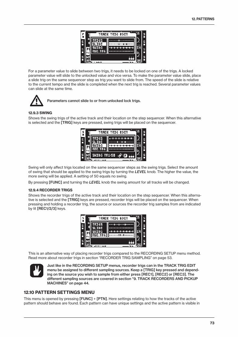
12. PATTERNS
73
For a parameter value to slide between two trigs, it needs to be locked on one of the trigs. A locked parameter value will slide to the unlocked value and vice versa. To make the parameter value slide, place a slide trig on the same sequencer step as trig you want to slide from. The speed of the slide is relative to the current tempo and the slide is completed when the next trig is reached. Several parameter values can slide at the same time.
Parameters cannot slide to or from unlocked lock trigs.
12.9.3 SWINGShows the swing trigs of the active track and their location on the step sequencer. When this alternative is selected and the [TRIG] keys are pressed, swing trigs will be placed on the sequencer.
Swing will only affect trigs located on the same sequencer steps as the swing trigs. Select the amount of swing that should be applied to the swing trigs by turning the LEVEL knob. The higher the value, the more swing will be applied. A setting of 50 equals no swing.
By pressing [FUNC] and turning the LEVEL knob the swing amount for all tracks will be changed.
12.9.4 RECORDER TRIGSShows the recorder trigs of the active track and their location on the step sequencer. When this alterna-tive is selected and the [TRIG] keys are pressed, recorder trigs will be placed on the sequencer. When pressing and holding a recorder trig, the source or sources the recorder trig samples from are indicated by lit [REC1/2/3] keys.
This is an alternative way of placing recorder trigs compared to the RECORDING SETUP menu method. Read more about recorder trigs in section “RECORDER TRIG SAMPLING” on page 53.
Just like in the RECORDING SETUP menus, recorder trigs can in the TRACK TRIG EDIT menu be assigned to different sampling sources. Keep a [TRIG] key pressed and depend-ing on the source you wish to sample from either press [REC1], [REC2] or [REC3]. The different sampling sources are covered in section “9. TRACK RECORDERS AND PICKUP MACHINES” on page 44.
12.10 PATTERN SETTINGS MENUThis menu is opened by pressing [FUNC] + [PTN]. Here settings relating to how the tracks of the active pattern should behave are found. Each pattern can have unique settings and the active pattern is visible in
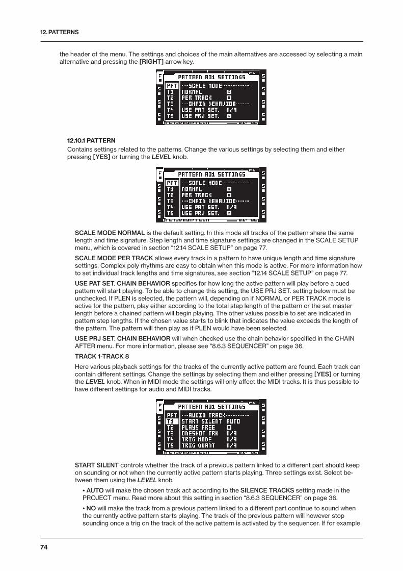
12. PATTERNS
74
the header of the menu. The settings and choices of the main alternatives are accessed by selecting a main alternative and pressing the [RIGHT] arrow key.
12.10.1 PATTERNContains settings related to the patterns. Change the various settings by selecting them and either pressing [YES] or turning the LEVEL knob.
SCALE MODE NORMAL is the default setting. In this mode all tracks of the pattern share the same length and time signature. Step length and time signature settings are changed in the SCALE SETUP menu, which is covered in section “12.14 SCALE SETUP” on page 77.
SCALE MODE PER TRACK allows every track in a pattern to have unique length and time signature settings. Complex poly rhythms are easy to obtain when this mode is active. For more information how to set individual track lengths and time signatures, see section “12.14 SCALE SETUP” on page 77.
USE PAT SET. CHAIN BEHAVIOR specifies for how long the active pattern will play before a cued pattern will start playing. To be able to change this setting, the USE PRJ SET. setting below must be unchecked. If PLEN is selected, the pattern will, depending on if NORMAL or PER TRACK mode is active for the pattern, play either according to the total step length of the pattern or the set master length before a chained pattern will begin playing. The other values possible to set are indicated in pattern step lengths. If the chosen value starts to blink that indicates the value exceeds the length of the pattern. The pattern will then play as if PLEN would have been selected.
USE PRJ SET. CHAIN BEHAVIOR will when checked use the chain behavior specified in the CHAIN AFTER menu. For more information, please see “8.6.3 SEQUENCER” on page 36.
TRACK 1-TRACK 8
Here various playback settings for the tracks of the currently active pattern are found. Each track can contain different settings. Change the settings by selecting them and either pressing [YES] or turning the LEVEL knob. When in MIDI mode the settings will only affect the MIDI tracks. It is thus possible to have different settings for audio and MIDI tracks.
START SILENT controls whether the track of a previous pattern linked to a different part should keep on sounding or not when the currently active pattern starts playing. Three settings exist. Select be-tween them using the LEVEL knob.
• AUTO will make the chosen track act according to the SILENCE TRACKS setting made in the PROJECT menu. Read more about this setting in section “8.6.3 SEQUENCER” on page 36.
• NO will make the track from a previous pattern linked to a different part continue to sound when the currently active pattern starts playing. The track of the previous pattern will however stop sounding once a trig on the track of the active pattern is activated by the sequencer. If for example
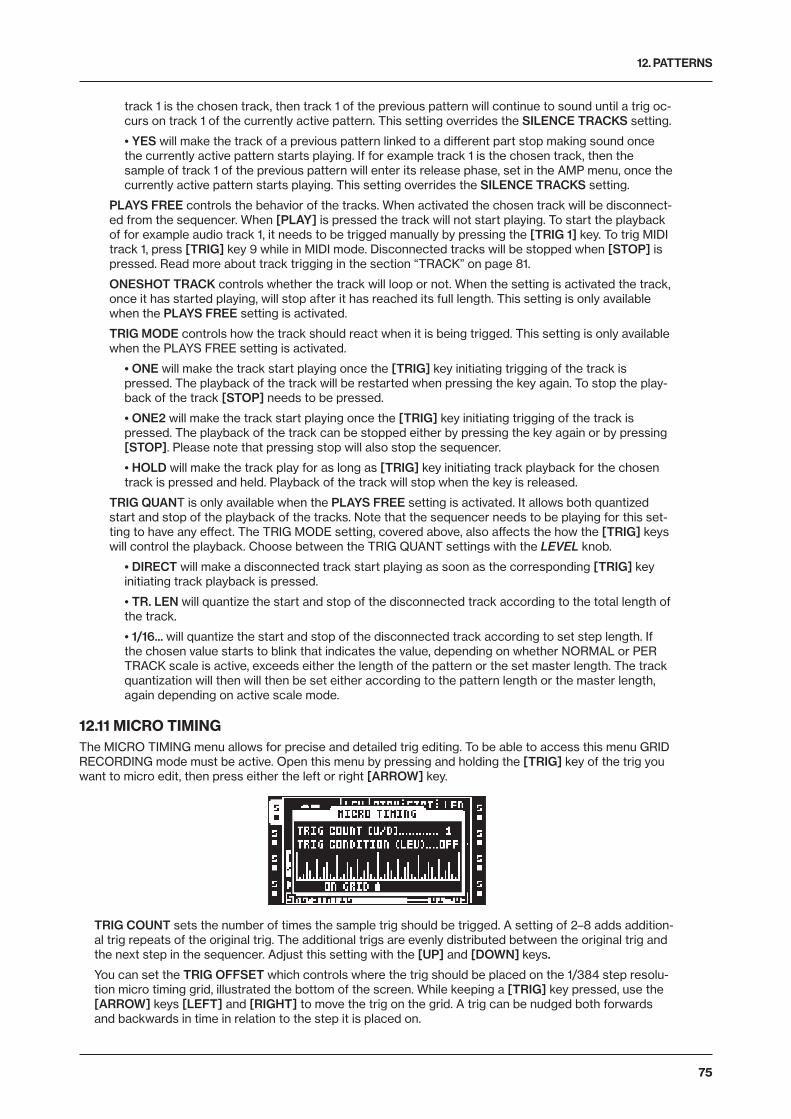
12. PATTERNS
75
track 1 is the chosen track, then track 1 of the previous pattern will continue to sound until a trig oc-curs on track 1 of the currently active pattern. This setting overrides the SILENCE TRACKS setting.
• YES will make the track of a previous pattern linked to a different part stop making sound once the currently active pattern starts playing. If for example track 1 is the chosen track, then the sample of track 1 of the previous pattern will enter its release phase, set in the AMP menu, once the currently active pattern starts playing. This setting overrides the SILENCE TRACKS setting.
PLAYS FREE controls the behavior of the tracks. When activated the chosen track will be disconnect-ed from the sequencer. When [PLAY] is pressed the track will not start playing. To start the playback of for example audio track 1, it needs to be trigged manually by pressing the [TRIG 1] key. To trig MIDI track 1, press [TRIG] key 9 while in MIDI mode. Disconnected tracks will be stopped when [STOP] is pressed. Read more about track trigging in the section “TRACK” on page 81.
ONESHOT TRACK controls whether the track will loop or not. When the setting is activated the track, once it has started playing, will stop after it has reached its full length. This setting is only available when the PLAYS FREE setting is activated.
TRIG MODE controls how the track should react when it is being trigged. This setting is only available when the PLAYS FREE setting is activated.
• ONE will make the track start playing once the [TRIG] key initiating trigging of the track is pressed. The playback of the track will be restarted when pressing the key again. To stop the play-back of the track [STOP] needs to be pressed.
• ONE2 will make the track start playing once the [TRIG] key initiating trigging of the track is pressed. The playback of the track can be stopped either by pressing the key again or by pressing [STOP]. Please note that pressing stop will also stop the sequencer.
• HOLD will make the track play for as long as [TRIG] key initiating track playback for the chosen track is pressed and held. Playback of the track will stop when the key is released.
TRIG QUANT is only available when the PLAYS FREE setting is activated. It allows both quantized start and stop of the playback of the tracks. Note that the sequencer needs to be playing for this set-ting to have any effect. The TRIG MODE setting, covered above, also affects the how the [TRIG] keys will control the playback. Choose between the TRIG QUANT settings with the LEVEL knob.
• DIRECT will make a disconnected track start playing as soon as the corresponding [TRIG] key initiating track playback is pressed.
• TR. LEN will quantize the start and stop of the disconnected track according to the total length of the track.
• 1/16... will quantize the start and stop of the disconnected track according to set step length. If the chosen value starts to blink that indicates the value, depending on whether NORMAL or PER TRACK scale is active, exceeds either the length of the pattern or the set master length. The track quantization will then will then be set either according to the pattern length or the master length, again depending on active scale mode.
12.11 MICRO TIMINGThe MICRO TIMING menu allows for precise and detailed trig editing. To be able to access this menu GRID RECORDING mode must be active. Open this menu by pressing and holding the [TRIG] key of the trig you want to micro edit, then press either the left or right [ARROW] key.
TRIG COUNT sets the number of times the sample trig should be trigged. A setting of 2–8 adds addition-al trig repeats of the original trig. The additional trigs are evenly distributed between the original trig and the next step in the sequencer. Adjust this setting with the [UP] and [DOWN] keys.
You can set the TRIG OFFSET which controls where the trig should be placed on the 1/384 step resolu-tion micro timing grid, illustrated the bottom of the screen. While keeping a [TRIG] key pressed, use the [ARROW] keys [LEFT] and [RIGHT] to move the trig on the grid. A trig can be nudged both forwards and backwards in time in relation to the step it is placed on.
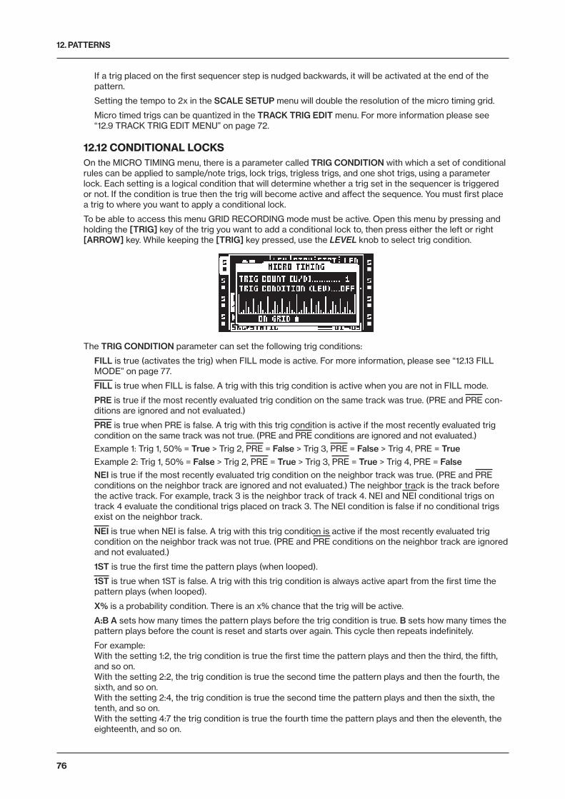
12. PATTERNS
76
If a trig placed on the first sequencer step is nudged backwards, it will be activated at the end of the pattern.
Setting the tempo to 2x in the SCALE SETUP menu will double the resolution of the micro timing grid.
Micro timed trigs can be quantized in the TRACK TRIG EDIT menu. For more information please see “12.9 TRACK TRIG EDIT MENU” on page 72.
12.12 CONDITIONAL LOCKSOn the MICRO TIMING menu, there is a parameter called TRIG CONDITION with which a set of conditional rules can be applied to sample/note trigs, lock trigs, trigless trigs, and one shot trigs, using a parameter lock. Each setting is a logical condition that will determine whether a trig set in the sequencer is triggered or not. If the condition is true then the trig will become active and affect the sequence. You must first place a trig to where you want to apply a conditional lock.
To be able to access this menu GRID RECORDING mode must be active. Open this menu by pressing and holding the [TRIG] key of the trig you want to add a conditional lock to, then press either the left or right [ARROW] key. While keeping the [TRIG] key pressed, use the LEVEL knob to select trig condition.
The TRIG CONDITION parameter can set the following trig conditions:
FILL is true (activates the trig) when FILL mode is active. For more information, please see “12.13 FILL MODE” on page 77.
FILL is true when FILL is false. A trig with this trig condition is active when you are not in FILL mode.
PRE is true if the most recently evaluated trig condition on the same track was true. (PRE and PRE con-ditions are ignored and not evaluated.)
PRE is true when PRE is false. A trig with this trig condition is active if the most recently evaluated trig condition on the same track was not true. (PRE and PRE conditions are ignored and not evaluated.)
Example 1: Trig 1, 50% = True > Trig 2, PRE = False > Trig 3, PRE = False > Trig 4, PRE = TrueExample 2: Trig 1, 50% = False > Trig 2, PRE = True > Trig 3, PRE = True > Trig 4, PRE = FalseNEI is true if the most recently evaluated trig condition on the neighbor track was true. (PRE and PRE conditions on the neighbor track are ignored and not evaluated.) The neighbor track is the track before the active track. For example, track 3 is the neighbor track of track 4. NEI and NEI conditional trigs on track 4 evaluate the conditional trigs placed on track 3. The NEI condition is false if no conditional trigs exist on the neighbor track.
NEI is true when NEI is false. A trig with this trig condition is active if the most recently evaluated trig condition on the neighbor track was not true. (PRE and PRE conditions on the neighbor track are ignored and not evaluated.)
1ST is true the first time the pattern plays (when looped).
1ST is true when 1ST is false. A trig with this trig condition is always active apart from the first time the pattern plays (when looped).
X% is a probability condition. There is an x% chance that the trig will be active.
A:B A sets how many times the pattern plays before the trig condition is true. B sets how many times the pattern plays before the count is reset and starts over again. This cycle then repeats indefinitely.
For example: With the setting 1:2, the trig condition is true the first time the pattern plays and then the third, the fifth, and so on. With the setting 2:2, the trig condition is true the second time the pattern plays and then the fourth, the sixth, and so on. With the setting 2:4, the trig condition is true the second time the pattern plays and then the sixth, the tenth, and so on. With the setting 4:7 the trig condition is true the fourth time the pattern plays and then the eleventh, the eighteenth, and so on.
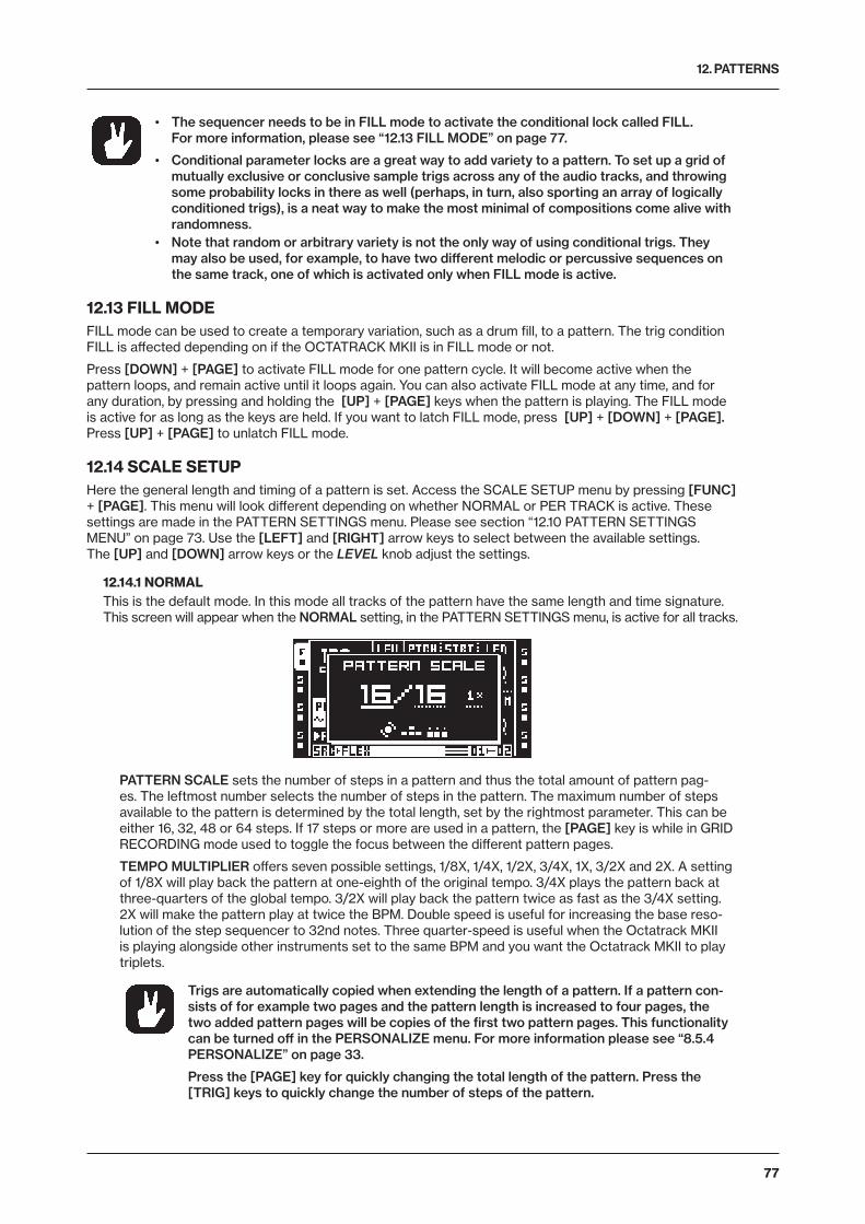
12. PATTERNS
77
• The sequencer needs to be in FILL mode to activate the conditional lock called FILL. For more information, please see “12.13 FILL MODE” on page 77.
• Conditional parameter locks are a great way to add variety to a pattern. To set up a grid of mutually exclusive or conclusive sample trigs across any of the audio tracks, and throwing some probability locks in there as well (perhaps, in turn, also sporting an array of logically conditioned trigs), is a neat way to make the most minimal of compositions come alive with randomness.
• Note that random or arbitrary variety is not the only way of using conditional trigs. They may also be used, for example, to have two different melodic or percussive sequences on the same track, one of which is activated only when FILL mode is active.
12.13 FILL MODEFILL mode can be used to create a temporary variation, such as a drum fill, to a pattern. The trig condition FILL is affected depending on if the OCTATRACK MKII is in FILL mode or not.
Press [DOWN] + [PAGE] to activate FILL mode for one pattern cycle. It will become active when the pattern loops, and remain active until it loops again. You can also activate FILL mode at any time, and for any duration, by pressing and holding the [UP] + [PAGE] keys when the pattern is playing. The FILL mode is active for as long as the keys are held. If you want to latch FILL mode, press [UP] + [DOWN] + [PAGE]. Press [UP] + [PAGE] to unlatch FILL mode.
12.14 SCALE SETUPHere the general length and timing of a pattern is set. Access the SCALE SETUP menu by pressing [FUNC] + [PAGE]. This menu will look different depending on whether NORMAL or PER TRACK is active. These settings are made in the PATTERN SETTINGS menu. Please see section “12.10 PATTERN SETTINGS MENU” on page 73. Use the [LEFT] and [RIGHT] arrow keys to select between the available settings. The [UP] and [DOWN] arrow keys or the LEVEL knob adjust the settings.
12.14.1 NORMALThis is the default mode. In this mode all tracks of the pattern have the same length and time signature. This screen will appear when the NORMAL setting, in the PATTERN SETTINGS menu, is active for all tracks.
PATTERN SCALE sets the number of steps in a pattern and thus the total amount of pattern pag-es. The leftmost number selects the number of steps in the pattern. The maximum number of steps available to the pattern is determined by the total length, set by the rightmost parameter. This can be either 16, 32, 48 or 64 steps. If 17 steps or more are used in a pattern, the [PAGE] key is while in GRID RECORDING mode used to toggle the focus between the different pattern pages.
TEMPO MULTIPLIER offers seven possible settings, 1/8X, 1/4X, 1/2X, 3/4X, 1X, 3/2X and 2X. A setting of 1/8X will play back the pattern at one-eighth of the original tempo. 3/4X plays the pattern back at three-quarters of the global tempo. 3/2X will play back the pattern twice as fast as the 3/4X setting. 2X will make the pattern play at twice the BPM. Double speed is useful for increasing the base reso-lution of the step sequencer to 32nd notes. Three quarter-speed is useful when the Octatrack MKII is playing alongside other instruments set to the same BPM and you want the Octatrack MKII to play triplets.
Trigs are automatically copied when extending the length of a pattern. If a pattern con-sists of for example two pages and the pattern length is increased to four pages, the two added pattern pages will be copies of the first two pattern pages. This functionality can be turned off in the PERSONALIZE menu. For more information please see “8.5.4 PERSONALIZE” on page 33.
Press the [PAGE] key for quickly changing the total length of the pattern. Press the [TRIG] keys to quickly change the number of steps of the pattern.
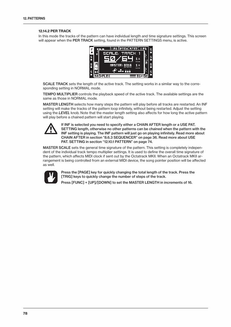
12. PATTERNS
78
12.14.2 PER TRACKIn this mode the tracks of the pattern can have individual length and time signature settings. This screen will appear when the PER TRACK setting, found in the PATTERN SETTINGS menu, is active.
SCALE TRACK sets the length of the active track. The setting works in a similar way to the corre-sponding setting in NORMAL mode.
TEMPO MULTIPLIER controls the playback speed of the active track. The available settings are the same as those in NORMAL mode.
MASTER LENGTH selects how many steps the pattern will play before all tracks are restarted. An INF setting will make the tracks of the pattern loop infinitely, without being restarted. Adjust the setting using the LEVEL knob. Note that the master length setting also affects for how long the active pattern will play before a chained pattern will start playing.
If INF is selected you need to specify either a CHAIN AFTER length or a USE PAT. SETTING length, otherwise no other patterns can be chained when the pattern with the INF setting is playing. The INF pattern will just go on playing infinitely. Read more about CHAIN AFTER in section “8.6.3 SEQUENCER” on page 36. Read more about USE PAT. SETTING in section “12.10.1 PATTERN” on page 74.
MASTER SCALE sets the general time signature of the pattern. This setting is completely indepen-dent of the individual track tempo multiplier settings. It is used to define the overall time signature of the pattern, which affects MIDI clock if sent out by the Octatrack MKII. When an Octatrack MKII ar-rangement is being controlled from an external MIDI device, the song pointer position will be affected as well.
Press the [PAGE] key for quickly changing the total length of the track. Press the [TRIG] keys to quickly change the number of steps of the track.
Press [FUNC] + [UP]/[DOWN] to set the MASTER LENGTH in increments of 16.
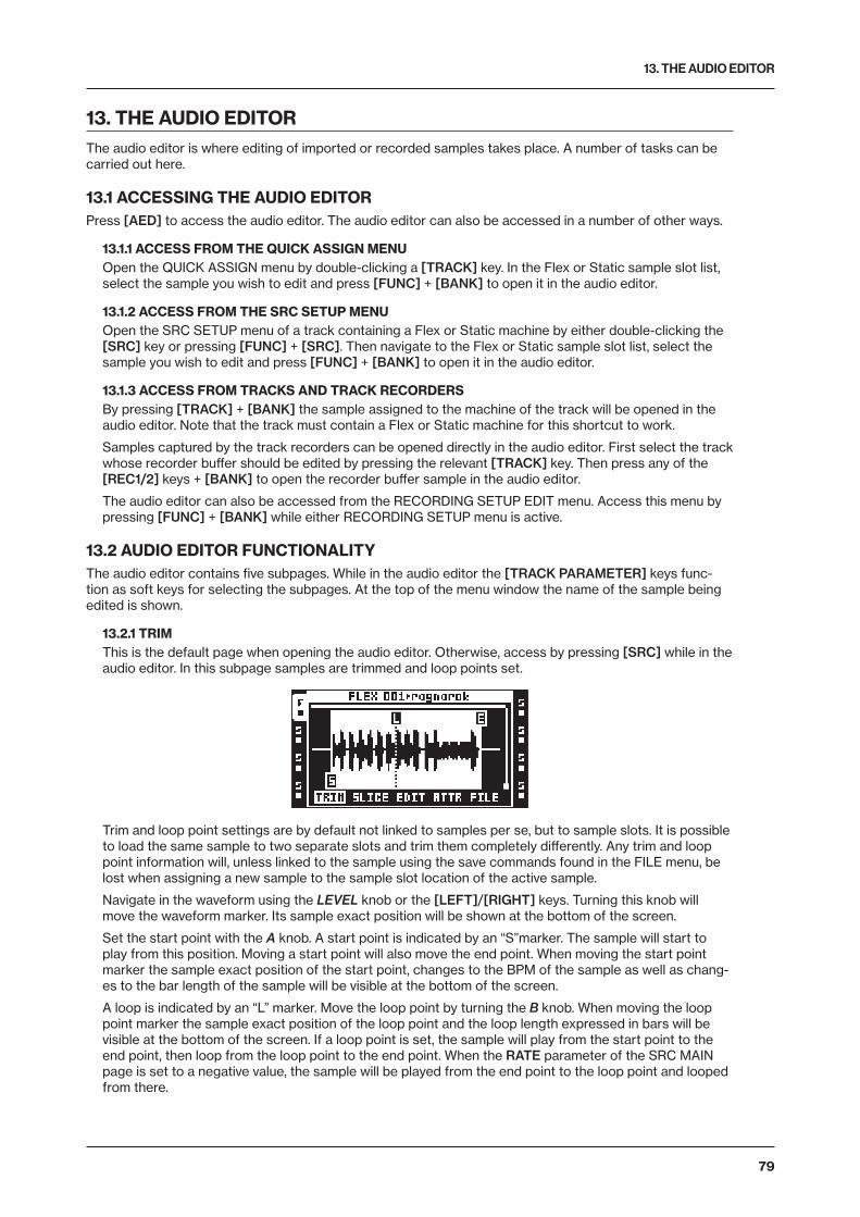
13. THE AUDIO EDITOR
79
13. THE AUDIO EDITORThe audio editor is where editing of imported or recorded samples takes place. A number of tasks can be carried out here.
13.1 ACCESSING THE AUDIO EDITORPress [AED] to access the audio editor. The audio editor can also be accessed in a number of other ways.
13.1.1 ACCESS FROM THE QUICK ASSIGN MENUOpen the QUICK ASSIGN menu by double-clicking a [TRACK] key. In the Flex or Static sample slot list, select the sample you wish to edit and press [FUNC] + [BANK] to open it in the audio editor.
13.1.2 ACCESS FROM THE SRC SETUP MENUOpen the SRC SETUP menu of a track containing a Flex or Static machine by either double-clicking the [SRC] key or pressing [FUNC] + [SRC]. Then navigate to the Flex or Static sample slot list, select the sample you wish to edit and press [FUNC] + [BANK] to open it in the audio editor.
13.1.3 ACCESS FROM TRACKS AND TRACK RECORDERSBy pressing [TRACK] + [BANK] the sample assigned to the machine of the track will be opened in the audio editor. Note that the track must contain a Flex or Static machine for this shortcut to work.
Samples captured by the track recorders can be opened directly in the audio editor. First select the track whose recorder buffer should be edited by pressing the relevant [TRACK] key. Then press any of the [REC1/2] keys + [BANK] to open the recorder buffer sample in the audio editor.
The audio editor can also be accessed from the RECORDING SETUP EDIT menu. Access this menu by pressing [FUNC] + [BANK] while either RECORDING SETUP menu is active.
13.2 AUDIO EDITOR FUNCTIONALITYThe audio editor contains five subpages. While in the audio editor the [TRACK PARAMETER] keys func-tion as soft keys for selecting the subpages. At the top of the menu window the name of the sample being edited is shown.
13.2.1 TRIMThis is the default page when opening the audio editor. Otherwise, access by pressing [SRC] while in the audio editor. In this subpage samples are trimmed and loop points set.
Trim and loop point settings are by default not linked to samples per se, but to sample slots. It is possible to load the same sample to two separate slots and trim them completely differently. Any trim and loop point information will, unless linked to the sample using the save commands found in the FILE menu, be lost when assigning a new sample to the sample slot location of the active sample.
Navigate in the waveform using the LEVEL knob or the [LEFT]/[RIGHT] keys. Turning this knob will move the waveform marker. Its sample exact position will be shown at the bottom of the screen.
Set the start point with the A knob. A start point is indicated by an “S”marker. The sample will start to play from this position. Moving a start point will also move the end point. When moving the start point marker the sample exact position of the start point, changes to the BPM of the sample as well as chang-es to the bar length of the sample will be visible at the bottom of the screen.
A loop is indicated by an “L” marker. Move the loop point by turning the B knob. When moving the loop point marker the sample exact position of the loop point and the loop length expressed in bars will be visible at the bottom of the screen. If a loop point is set, the sample will play from the start point to the end point, then loop from the loop point to the end point. When the RATE parameter of the SRC MAIN page is set to a negative value, the sample will be played from the end point to the loop point and looped from there.
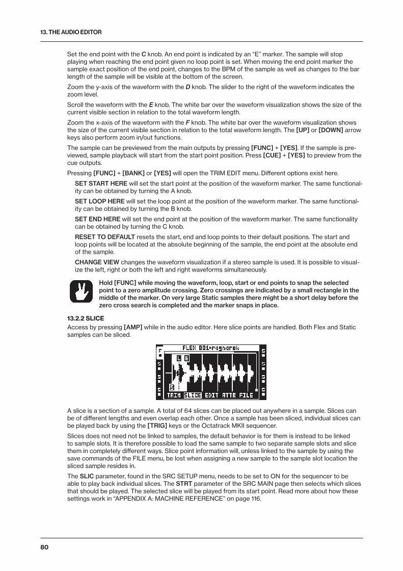
13. THE AUDIO EDITOR
80
Set the end point with the C knob. An end point is indicated by an “E” marker. The sample will stop playing when reaching the end point given no loop point is set. When moving the end point marker the sample exact position of the end point, changes to the BPM of the sample as well as changes to the bar length of the sample will be visible at the bottom of the screen.
Zoom the y-axis of the waveform with the D knob. The slider to the right of the waveform indicates the zoom level.
Scroll the waveform with the E knob. The white bar over the waveform visualization shows the size of the current visible section in relation to the total waveform length.
Zoom the x-axis of the waveform with the F knob. The white bar over the waveform visualization shows the size of the current visible section in relation to the total waveform length. The [UP] or [DOWN] arrow keys also perform zoom in/out functions.
The sample can be previewed from the main outputs by pressing [FUNC] + [YES]. If the sample is pre-viewed, sample playback will start from the start point position. Press [CUE] + [YES] to preview from the cue outputs.
Pressing [FUNC] + [BANK] or [YES] will open the TRIM EDIT menu. Different options exist here.
SET START HERE will set the start point at the position of the waveform marker. The same functional-ity can be obtained by turning the A knob.
SET LOOP HERE will set the loop point at the position of the waveform marker. The same functional-ity can be obtained by turning the B knob.
SET END HERE will set the end point at the position of the waveform marker. The same functionality can be obtained by turning the C knob.
RESET TO DEFAULT resets the start, end and loop points to their default positions. The start and loop points will be located at the absolute beginning of the sample, the end point at the absolute end of the sample.
CHANGE VIEW changes the waveform visualization if a stereo sample is used. It is possible to visual-ize the left, right or both the left and right waveforms simultaneously.
Hold [FUNC] while moving the waveform, loop, start or end points to snap the selected point to a zero amplitude crossing. Zero crossings are indicated by a small rectangle in the middle of the marker. On very large Static samples there might be a short delay before the zero cross search is completed and the marker snaps in place.
13.2.2 SLICEAccess by pressing [AMP] while in the audio editor. Here slice points are handled. Both Flex and Static samples can be sliced.
A slice is a section of a sample. A total of 64 slices can be placed out anywhere in a sample. Slices can be of different lengths and even overlap each other. Once a sample has been sliced, individual slices can be played back by using the [TRIG] keys or the Octatrack MKII sequencer.
Slices does not need not be linked to samples, the default behavior is for them is instead to be linked to sample slots. It is therefore possible to load the same sample to two separate sample slots and slice them in completely different ways. Slice point information will, unless linked to the sample by using the save commands of the FILE menu, be lost when assigning a new sample to the sample slot location the sliced sample resides in.
The SLIC parameter, found in the SRC SETUP menu, needs to be set to ON for the sequencer to be able to play back individual slices. The STRT parameter of the SRC MAIN page then selects which slices that should be played. The selected slice will be played from its start point. Read more about how these settings work in “APPENDIX A: MACHINE REFERENCE” on page 116.
13. THE AUDIO EDITOR
81
Pressing [FUNC] + [BANK] or [YES] opens the SLICE EDIT menu. Different options will appear, depend-ing on whether the SLICE EDIT menu is opened while a slice is highlighted or not.
ADD SLICE HERE adds a slice. The marker must be on a non-sliced area of the waveform for this alternative to appear.
DISABLE LOOP will delete the loop point of the selected slice. This alternative only appears when the waveform marker is positioned on a slice.
DELETE SLICE will delete the selected slice. This alternative only appears when the waveform marker is positioned on a slice.
REVERSE SLICE will reverse the audio content of the selected slice.
NORMALIZE SLICE will apply normalization to the selected slice.
DELETE ALL SLICES will delete all slices.
CREATE SLICE GRID will create a number of slices spread out between the start and end points set in the TRIM menu. The slice grid can consist of 2, 3, 4, 6, 8, 12, 16, 24, 32, 48 or 64 slices. After creating the slice grid a prompt will appear asking “ALIGN MARKERS TO ZERO-CROSSES?”. If [YES] is pressed the slices in the grid will be adjusted to the nearest zero amplitude crossings. If [NO] is pressed the slices will be spread out evenly and all slices will have the exact same length. This menu can also be accessed by pressing [FUNC] + [AED].
CREATE LINEAR LOCKS will, given the active track contains a Flex or Static machine, automatically set the SLIC parameter in the SRC SETUP menu to ON and lock the STRT parameter of sample trigs already present on the active track. The STRT parameter of the first sample trig will be locked to SL1, the STRT parameter of the second sample trig locked to SL2 and so on. The locked STRT values are dependent on the amount of slices in the sample. If only one slice exist all sample trigs will for example be locked to SL1. If SLIC is turned off, the value of the STRT locks will revert to approximations of the slice start points:
SLIC set to ON, STRT set to SL1 = STRT 0 when SLIC is set to OFF
SLIC set to ON, STRT set to SL2 = STRT 2 when SLIC is set to OFF
SLIC set to ON, STRT set to SL3 = STRT 4 when SLIC is set to OFF
SLIC set to ON, STRT set to SL4 = STRT 6 when SLIC is set to OFF
Note that turning off SLIC may change the structure of a sample completely.
CREATE RANDOM LOCKS works just like the CREATE LINEAR LOCKS command, but randomizes the locked STRT parameters of the sample trigs.
CHANGE VIEW changes the waveform visualization if a stereo sample is used. It works just like the same command found in the TRIM EDIT menu.
Use the waveform marker or press the [RIGHT] or [LEFT] arrow keys to navigate between the slices. A slice needs to be active, which is indicated by inverted graphics, for slice start, loop and end points to be set. When a slice is active knob A sets the start point, knob B sets the loop point and knob C sets the end point. When moving the start, loop or end points, their sample exact position will be shown at the bottom of the screen.
Due to the nature of Compact Flash cards, Static sample slices might not be played back correctly when modulating the STRT parameter with the crossfader or the track LFOs. The start point of the slices might then be off. This problem is avoided when using param-eter locks. Flex samples don’t have this problem because of them being stored in the RAM memory.
STRT values exceeding the amount of slices will select the last slice. If the sample con-tains for example 16 slices, STRT values ranging from SL17 - SL64 will select slice 16.
Hold [FUNC] while moving the waveform, loop, start or end markers to snap the selected marker to a zero amplitude crossing. Zero crossings are indicated by a small rectangle in the middle of the marker. On very large Static samples there might be a short delay before the zero cross search is completed and the marker snaps in place.
The active slice can be previewed from the main outputs by pressing [FUNC] + [YES]. If no slice is selected the preview listening will start from the location of the waveform marker. Press [CUE] + [YES] to preview from the cue outputs.
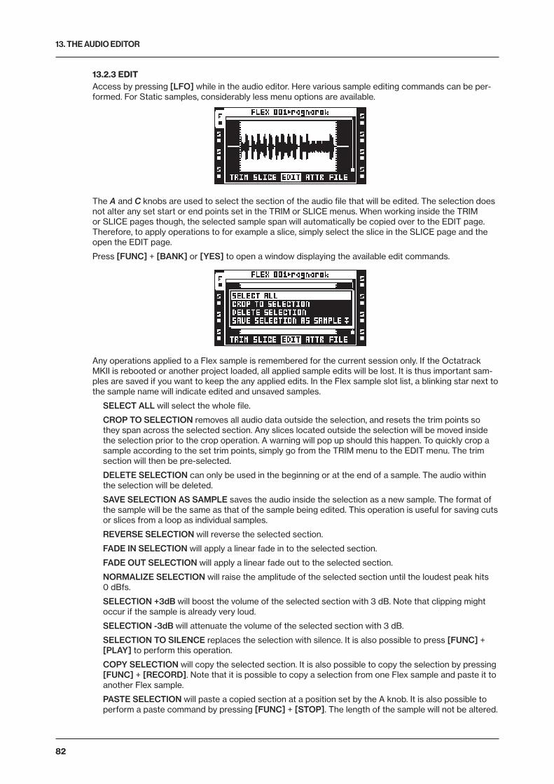
13. THE AUDIO EDITOR
82
13.2.3 EDITAccess by pressing [LFO] while in the audio editor. Here various sample editing commands can be per-formed. For Static samples, considerably less menu options are available.
The A and C knobs are used to select the section of the audio file that will be edited. The selection does not alter any set start or end points set in the TRIM or SLICE menus. When working inside the TRIM or SLICE pages though, the selected sample span will automatically be copied over to the EDIT page. Therefore, to apply operations to for example a slice, simply select the slice in the SLICE page and the open the EDIT page.
Press [FUNC] + [BANK] or [YES] to open a window displaying the available edit commands.
Any operations applied to a Flex sample is remembered for the current session only. If the Octatrack MKII is rebooted or another project loaded, all applied sample edits will be lost. It is thus important sam-ples are saved if you want to keep the any applied edits. In the Flex sample slot list, a blinking star next to the sample name will indicate edited and unsaved samples.
SELECT ALL will select the whole file.
CROP TO SELECTION removes all audio data outside the selection, and resets the trim points so they span across the selected section. Any slices located outside the selection will be moved inside the selection prior to the crop operation. A warning will pop up should this happen. To quickly crop a sample according to the set trim points, simply go from the TRIM menu to the EDIT menu. The trim section will then be pre-selected.
DELETE SELECTION can only be used in the beginning or at the end of a sample. The audio within the selection will be deleted.
SAVE SELECTION AS SAMPLE saves the audio inside the selection as a new sample. The format of the sample will be the same as that of the sample being edited. This operation is useful for saving cuts or slices from a loop as individual samples.
REVERSE SELECTION will reverse the selected section.
FADE IN SELECTION will apply a linear fade in to the selected section.
FADE OUT SELECTION will apply a linear fade out to the selected section.
NORMALIZE SELECTION will raise the amplitude of the selected section until the loudest peak hits 0 dBfs.
SELECTION +3dB will boost the volume of the selected section with 3 dB. Note that clipping might occur if the sample is already very loud.
SELECTION -3dB will attenuate the volume of the selected section with 3 dB.
SELECTION TO SILENCE replaces the selection with silence. It is also possible to press [FUNC] + [PLAY] to perform this operation.
COPY SELECTION will copy the selected section. It is also possible to copy the selection by pressing [FUNC] + [RECORD]. Note that it is possible to copy a selection from one Flex sample and paste it to another Flex sample.
PASTE SELECTION will paste a copied section at a position set by the A knob. It is also possible to perform a paste command by pressing [FUNC] + [STOP]. The length of the sample will not be altered.

13. THE AUDIO EDITOR
83
Please note it is not possible to paste audio which overlaps with the copied data. The paste operation can work in different ways depending on the CHANGE PASTE MODE setting.
DUPLICATE SELECTION -> will copy the selected section and paste it right after the end of the selection. The total length of the sample will not be altered. This mode works like an automated copy/paste function and is therefore also affected by the CHANGE PASTE MODE setting. This command is handy when creating rolling/stutter effects.
DUPLICATE SELECTION <- will copy the selected section and paste it right before the start of the selection. The total length of the sample will not be altered. This mode works like an automated copy/paste function and is therefore also affected by the CHANGE PASTE MODE setting.
CHANGE PASTE MODE offers several settings. The setting chosen here affects both the PASTE SELECTION command and the two DUP SELECTION commands.
• PASTE 0dB is the default selection. Pasted content will replace the content already present.
• PASTE -6dB will attenuate pasted content by 6 dB.
• MIX 0dB will mix pasted content with the content already present.
• MIX -6dB will mix pasted content with the content already present. The mixed audio will at the same time be attenuated by 6 dB.
ROTATE POS TO START rotates the audio data so that the cursor position becomes the new start position of the sample.
MIX CHANNELS offers several settings.
• ADD CH L+R will merge the left and right channels of the selected section and distribute the merged audio to both the left and right channels.
• SUBTRACT CH L-R will subtract the right channel from the left channel and distribute the result to both the left and right channels.
• SUBTRACT CH R-L will subtract the left channel from the right channel and distribute the result to both the left and right channels.
• SWAP CH L/R will swap the left channel with the right and vice versa.
INVERT CHANNEL applies phase inversion to the selected section.
• INVERT CH L&R applies phase inversion to both the left and right channel of the selected section.
• INVERT CH L applies phase inversion to the left channel of the selected section.
• INVERT CH R applies phase inversion to the left channel of the selected section.
CAL BPM FROM SELECTION will calculate the BPM of the selection by assuming it contains a musi-cal length like 0.5 bars, 1 bar, 2 bars etc. The calculated BPM will be applied to the ORIGINAL TEMPO setting found in the ATTRIBUTES menu. Useful when calculation the BPM of a complete track. Select for example 1 bar and perform this command.
CHANGE PREVIEW MODE selects between preview listening modes. Preview listen through the main outputs by pressing [FUNC] + [YES]. Preview listen through the cue outputs by pressing [CUE] + [YES].
• PLAY ONCE will preview the selected section once.
• LOOP SELECTION will continuously loop the selected section when preview listening.
CHANGE VIEW selects how the audio file will be displayed on the screen. This setting is only relevant for stereo samples.
• CH L VIEW displays only the left channel of the audio file.
• CH R VIEW displays only the right channel of the audio file.
• STEREO VIEW displays both the left and the right channels.
13.2.4 ATTRIBUTESAccess by pressing [FX1] while in the audio editor. Here general information about the selected or active sample is found. The settings made here can be permanently linked to a sample using the save com-mands found in the FILE menu. For more information, please see “13.2.5 FILE” on page 85.
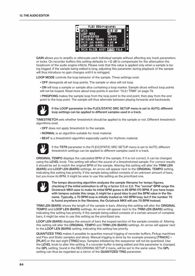
13. THE AUDIO EDITOR
84
GAIN allows you to amplify or attenuate each individual sample without affecting any track parameters or locks. On recorder buffers this setting defaults to +12 dB to compensate for the attenuation the headroom of the audio engine inflicts. Please note that this value is applied only when a sample is be-ing trigged. If the sample being edited is long, adjusting this parameter during playback of the sample will thus introduce no gain changes until it is retrigged.
LOOP MODE controls the loop behavior of the sample. Three settings exist.
• OFF disregards all set loop points. The sample or slice will not loop.
• ON will loop a sample or sample slice containing a loop marker. Sample slices without loop points will not be looped. Read more about loop points in section “13.2.1 TRIM” on page 79.
• PINGPONG makes the sample loop from the loop point to the end point, then play from the end point to the loop point. The sample will thus alternate between playing forwards and backwards.
If the LOOP parameter in the FLEX/STATIC SRC SETUP menu is set to AUTO, different loop settings can be applied to different samples used in a track.
TIMESTRETCH sets whether timestretch should be applied to the sample or not. Different timestretch algorithms exist.
• OFF does not apply timestretch to the sample.
• NORMAL is an algorithm suitable for most material.
• BEAT is a timestretch algorithm especially useful for rhythmic material.
If the TSTR parameter in the FLEX/STATIC SRC SETUP menu is set to AUTO, different timestretch settings can be applied to different samples used in a track.
ORIGINAL TEMPO displays the calculated BPM of the sample. If it is not correct, it can be changed using the LEVEL knob. This setting will affect the sound of a timestretched sample. For correct results it should be set to match the original BPM of the sample. Altering this setting will alter the TRIM LEN (BARS) and LOOP LEN (BARS) settings. An arrow will appear next to the ORIGINAL TEMPO setting, indicating this setting has priority. If the sample being edited consists of an unknown amount of bars, but you know its BPM, it might be wise to use this setting as the prioritized one.
The tempo discerning algorithm analyzes the sample filename for tempo figures, checking if the initial estimation is off by a factor 0.5 or 2.0. The ”normal” BPM range the Octatrack MKII uses to make its initial BPM guess is 85 BPM-170 BPM. If you have loops with tempos outside this range, it might be a good idea to put the BPM value in the file-name. Typically, a 70 BPM loop is initially loaded as 140 BPM loop, but if the number 70 is found anywhere in the filename, the Octatrack MKII will use 70 BPM instead.
TRIM LEN (BARS) shows the length of the sample in bars. Altering this setting will alter the ORIGINAL TEMPO and LOOP LEN (BARS) settings. An arrow will appear next to the TRIM LEN (BARS) setting, indicating this setting has priority. If the sample being edited consists of a certain amount of complete bars, it might be wise to use this setting as the prioritized one.
LOOP LEN (BARS) displays the amount of bars the looped section of the sample consists of. Altering this setting will alter the ORIGINAL TEMPO and TRIM LEN (BARS) settings. An arrow will appear next to the LOOP LEN (BARS) setting, indicating this setting has priority.
QUANTIZED TRIG makes it possible to quantize manual trigging of recorder buffers, Pickup machines and Flex and Static samples and slices. Manual trigging is done by for example pressing [TRACK] + [PLAY] or the last eight [TRIG] keys. Samples initiated by the sequencer will not be quantized. Use the LEVEL knob to alter this setting. If a recorder buffer is being edited and this parameter is changed, the QPL setting, found in the RECORDING SETUP 2 menu, will be set to the same value. The QPL setting can thus be regarded as a mirror of the QUANTIZED TRIG parameter.
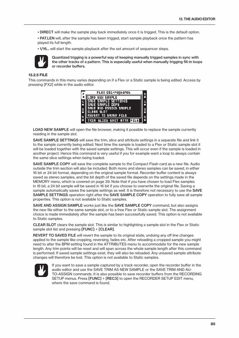
13. THE AUDIO EDITOR
85
• DIRECT will make the sample play back immediately once it is trigged. This is the default option.
• PAT.LEN will, after the sample has been trigged, start sample playback once the pattern has played its full length.
• 1/16... will start the sample playback after the set amount of sequencer steps.
Quantized trigging is a powerful way of keeping manually trigged samples in sync with the other tracks of a pattern. This is especially useful when manually trigging fill-in loops or recorder buffers.
13.2.5 FILEThis commands in this menu varies depending on if a Flex or a Static sample is being edited. Access by pressing [FX2] while in the audio editor.
LOAD NEW SAMPLE will open the file browser, making it possible to replace the sample currently residing in the sample slot.
SAVE SAMPLE SETTINGS will save the trim, slice and attribute settings in a separate file and link it to the sample currently being edited. Next time the sample is loaded to a Flex or Static sample slot it will be loaded together with the saved sample settings. This will occur even if the sample is loaded in another project. Hence this command is very useful if you for example want a loop to always contain the same slice settings when being loaded.
SAVE SAMPLE COPY will save the complete sample to the Compact Flash card as a new file. Audio outside the trim section will also be included. Both mono and stereo samples can be saved, in either 16 bit or 24 bit format, depending on the original sample format. Recorder buffer content is always saved as stereo samples, and the bit depth of the saved file depends on the settings made in the MEMORY menu, which is covered on page 39. Note that if you have chosen to load Flex samples in 16 bit, a 24 bit sample will be saved in 16 bit if you choose to overwrite the original file. Saving a sample automatically saves the sample settings as well. It is therefore not necessary to use the SAVE SAMPLE SETTINGS operation right after the SAVE SAMPLE COPY operation to fully save all sample properties. This option is not available to Static samples.
SAVE AND ASSIGN SAMPLE works just like the SAVE SAMPLE COPY command, but also assigns the new file either to the same sample slot, or to a free Flex or Static sample slot. The assignment choice is made immediately after the sample has been successfully saved. This option is not available to Static samples.
CLEAR SLOT clears the sample slot. This is similar to highlighting a sample slot in the Flex or Static sample slot list and pressing [FUNC] + [CLEAR].
REVERT TO SAVED FILE will revert the sample to its original state, undoing any off line changes applied to the sample like cropping, reversing, fades etc. After reloading a cropped sample you might need to alter the BPM setting found in the ATTRIBUTES menu to accommodate for the new sample length. Any trim points will be reset and will span across the whole sample length after this command is performed. If saved sample settings exist, they will also be reloaded. Any unsaved sample attribute changes will therefore be lost. This option is not available to Static samples.
If you want to save a sample captured by a track recorder, open the recorder buffer in the audio editor and use the SAVE TRIM AS NEW SAMPLE or the SAVE TRIM AND AU-TO-ASSIGN commands. It is also possible to save recorder buffers from the RECORDING SETUP menus. Press [FUNC] + [REC3] to open the RECORDER SETUP EDIT menu, where the save command is found.
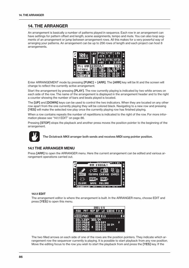
14. THE ARRANGER
86
14. THE ARRANGERAn arrangement is basically a number of patterns played in sequence. Each row in an arrangement can have settings for pattern offset and length, scene assignments, tempo and mute. You can also loop seg-ments of an arrangement or jump between arrangement rows. All this makes for a very powerful way of arranging your patterns. An arrangement can be up to 256 rows of length and each project can host 8 arrangements.
Enter ARRANGEMENT mode by pressing [FUNC] + [ARR]. The [ARR] key will be lit and the screen will change to reflect the currently active arrangement.
Start the arrangement by pressing [PLAY]. The row currently playing is indicated by two white arrows on each side of the row. The name of the arrangement is displayed in the arrangement header and to the right a counter showing the number of bars and beats played is located.
The [UP] and [DOWN] keys can be used to control the two indicators. When they are located on any other row apart from the one currently playing they will be colored black. Navigating to a new row and pressing [YES] will make the selected row play once the currently playing row has finished playing.
When a row contains repeats the number of repetitions is indicated to the right of the row. For more infor-mation please see “14.1.1 EDIT” on page 86.
Pressing [STOP] stops the playback and another press moves the position pointer to the beginning of the arrangement.
The Octatrack MKII arranger both sends and receives MIDI song pointer position.
14.1 THE ARRANGER MENUPress [ARR] to open the ARRANGER menu. Here the current arrangement can be edited and various ar-rangement operations carried out.
14.1.1 EDITThe arrangement editor is where the arrangement is built. In the ARRANGER menu, choose EDIT and press [YES] to open this menu.
The two filled arrows on each side of one of the rows are the position pointers. They indicate which ar-rangement row the sequencer currently is playing. It is possible to start playback from any row position. Move the editing focus to the row you wish to start the playback from and press the [YES] key. If the
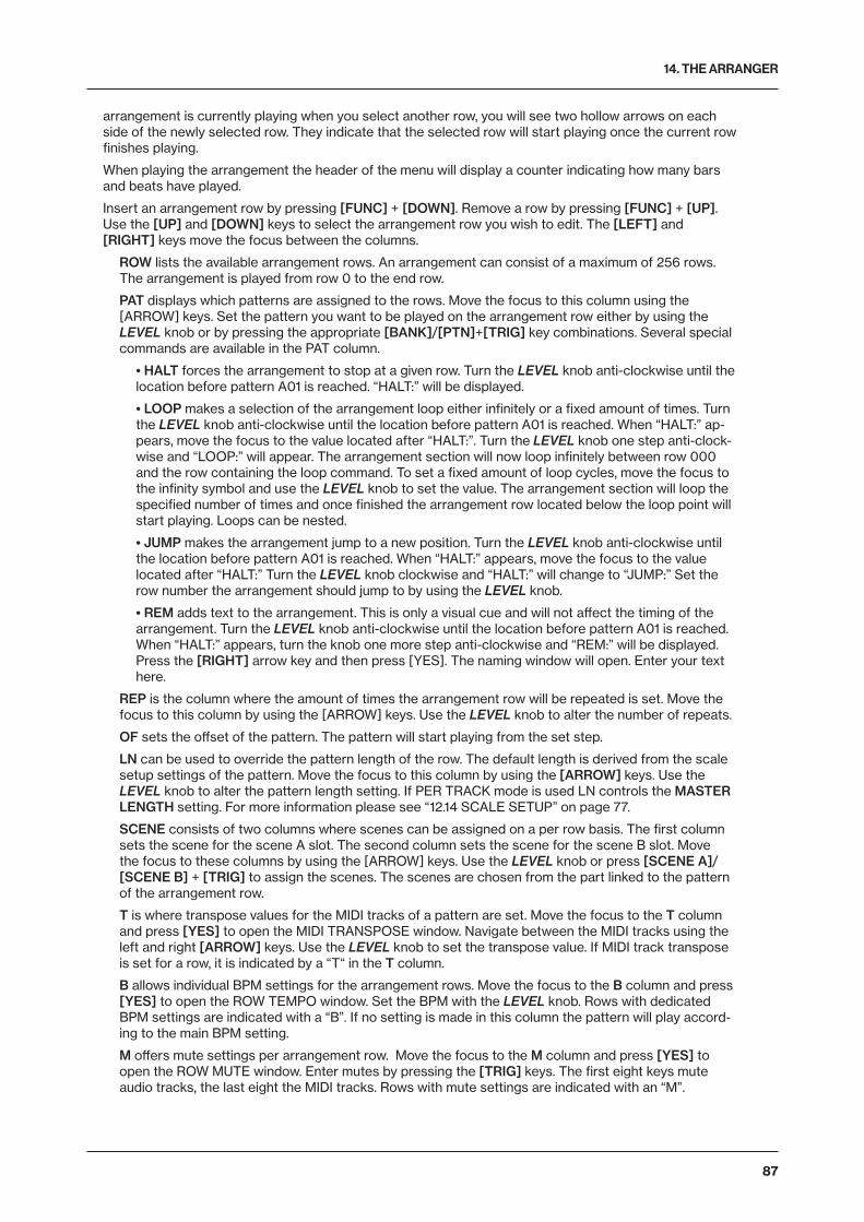
14. THE ARRANGER
87
arrangement is currently playing when you select another row, you will see two hollow arrows on each side of the newly selected row. They indicate that the selected row will start playing once the current row finishes playing.
When playing the arrangement the header of the menu will display a counter indicating how many bars and beats have played.
Insert an arrangement row by pressing [FUNC] + [DOWN]. Remove a row by pressing [FUNC] + [UP]. Use the [UP] and [DOWN] keys to select the arrangement row you wish to edit. The [LEFT] and [RIGHT] keys move the focus between the columns.
ROW lists the available arrangement rows. An arrangement can consist of a maximum of 256 rows. The arrangement is played from row 0 to the end row.
PAT displays which patterns are assigned to the rows. Move the focus to this column using the [ARROW] keys. Set the pattern you want to be played on the arrangement row either by using the LEVEL knob or by pressing the appropriate [BANK]/[PTN]+[TRIG] key combinations. Several special commands are available in the PAT column.
• HALT forces the arrangement to stop at a given row. Turn the LEVEL knob anti-clockwise until the location before pattern A01 is reached. “HALT:” will be displayed.
• LOOP makes a selection of the arrangement loop either infinitely or a fixed amount of times. Turn the LEVEL knob anti-clockwise until the location before pattern A01 is reached. When “HALT:” ap-pears, move the focus to the value located after “HALT:”. Turn the LEVEL knob one step anti-clock-wise and “LOOP:” will appear. The arrangement section will now loop infinitely between row 000 and the row containing the loop command. To set a fixed amount of loop cycles, move the focus to the infinity symbol and use the LEVEL knob to set the value. The arrangement section will loop the specified number of times and once finished the arrangement row located below the loop point will start playing. Loops can be nested.
• JUMP makes the arrangement jump to a new position. Turn the LEVEL knob anti-clockwise until the location before pattern A01 is reached. When “HALT:” appears, move the focus to the value located after “HALT:” Turn the LEVEL knob clockwise and “HALT:” will change to “JUMP:” Set the row number the arrangement should jump to by using the LEVEL knob.
• REM adds text to the arrangement. This is only a visual cue and will not affect the timing of the arrangement. Turn the LEVEL knob anti-clockwise until the location before pattern A01 is reached. When “HALT:” appears, turn the knob one more step anti-clockwise and “REM:” will be displayed. Press the [RIGHT] arrow key and then press [YES]. The naming window will open. Enter your text here.
REP is the column where the amount of times the arrangement row will be repeated is set. Move the focus to this column by using the [ARROW] keys. Use the LEVEL knob to alter the number of repeats.
OF sets the offset of the pattern. The pattern will start playing from the set step.
LN can be used to override the pattern length of the row. The default length is derived from the scale setup settings of the pattern. Move the focus to this column by using the [ARROW] keys. Use the LEVEL knob to alter the pattern length setting. If PER TRACK mode is used LN controls the MASTER LENGTH setting. For more information please see “12.14 SCALE SETUP” on page 77.
SCENE consists of two columns where scenes can be assigned on a per row basis. The first column sets the scene for the scene A slot. The second column sets the scene for the scene B slot. Move the focus to these columns by using the [ARROW] keys. Use the LEVEL knob or press [SCENE A]/[SCENE B] + [TRIG] to assign the scenes. The scenes are chosen from the part linked to the pattern of the arrangement row.
T is where transpose values for the MIDI tracks of a pattern are set. Move the focus to the T column and press [YES] to open the MIDI TRANSPOSE window. Navigate between the MIDI tracks using the left and right [ARROW] keys. Use the LEVEL knob to set the transpose value. If MIDI track transpose is set for a row, it is indicated by a “T“ in the T column.
B allows individual BPM settings for the arrangement rows. Move the focus to the B column and press [YES] to open the ROW TEMPO window. Set the BPM with the LEVEL knob. Rows with dedicated BPM settings are indicated with a “B”. If no setting is made in this column the pattern will play accord-ing to the main BPM setting.
M offers mute settings per arrangement row. Move the focus to the M column and press [YES] to open the ROW MUTE window. Enter mutes by pressing the [TRIG] keys. The first eight keys mute audio tracks, the last eight the MIDI tracks. Rows with mute settings are indicated with an “M”.
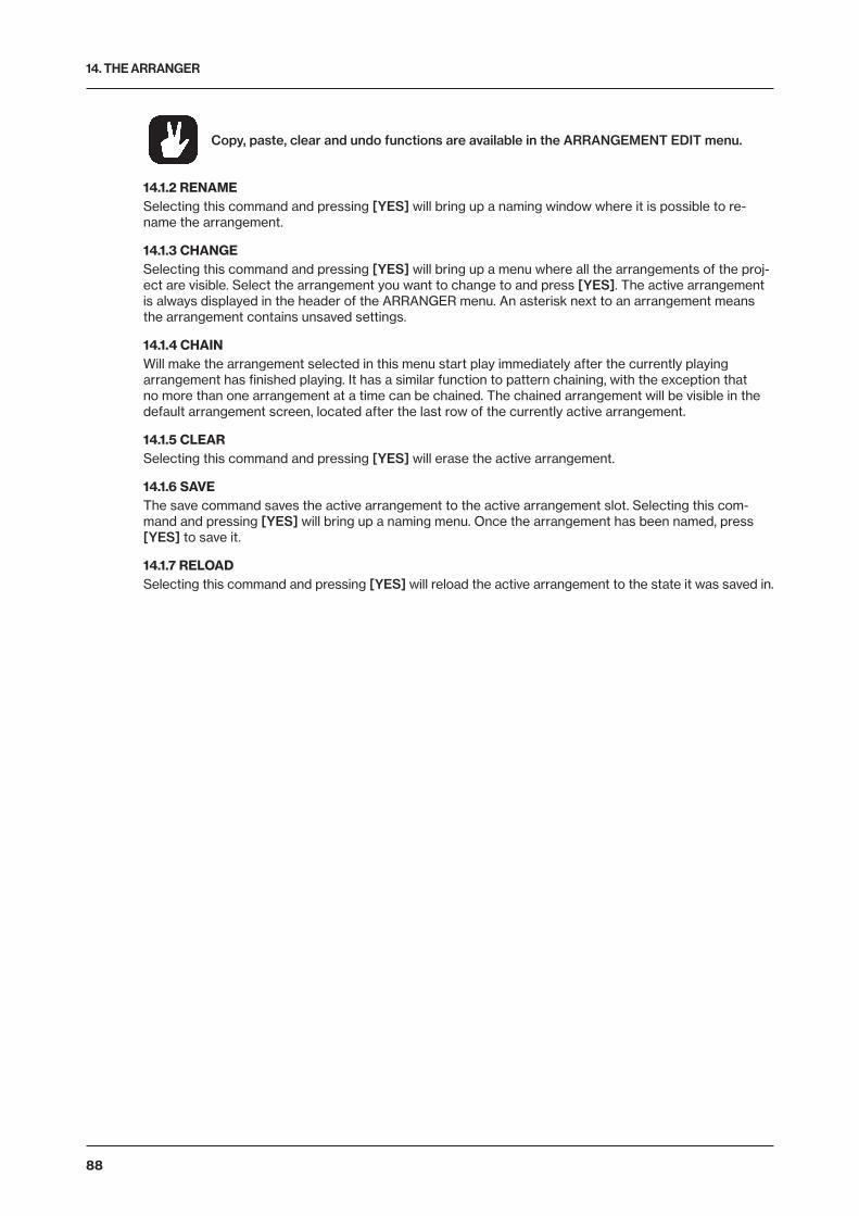
14. THE ARRANGER
88
Copy, paste, clear and undo functions are available in the ARRANGEMENT EDIT menu.
14.1.2 RENAMESelecting this command and pressing [YES] will bring up a naming window where it is possible to re-name the arrangement.
14.1.3 CHANGESelecting this command and pressing [YES] will bring up a menu where all the arrangements of the proj-ect are visible. Select the arrangement you want to change to and press [YES]. The active arrangement is always displayed in the header of the ARRANGER menu. An asterisk next to an arrangement means the arrangement contains unsaved settings.
14.1.4 CHAINWill make the arrangement selected in this menu start play immediately after the currently playing arrangement has finished playing. It has a similar function to pattern chaining, with the exception that no more than one arrangement at a time can be chained. The chained arrangement will be visible in the default arrangement screen, located after the last row of the currently active arrangement.
14.1.5 CLEARSelecting this command and pressing [YES] will erase the active arrangement.
14.1.6 SAVEThe save command saves the active arrangement to the active arrangement slot. Selecting this com-mand and pressing [YES] will bring up a naming menu. Once the arrangement has been named, press [YES] to save it.
14.1.7 RELOADSelecting this command and pressing [YES] will reload the active arrangement to the state it was saved in.
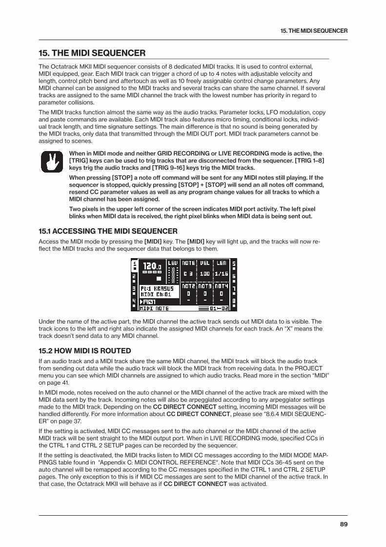
15. THE MIDI SEQUENCER
89
15. THE MIDI SEQUENCERThe Octatrack MKII MIDI sequencer consists of 8 dedicated MIDI tracks. It is used to control external, MIDI equipped, gear. Each MIDI track can trigger a chord of up to 4 notes with adjustable velocity and length, control pitch bend and aftertouch as well as 10 freely assignable control change parameters. Any MIDI channel can be assigned to the MIDI tracks and several tracks can share the same channel. If several tracks are assigned to the same MIDI channel the track with the lowest number has priority in regard to parameter collisions.
The MIDI tracks function almost the same way as the audio tracks. Parameter locks, LFO modulation, copy and paste commands are available. Each MIDI track also features micro timing, conditional locks, individ-ual track length, and time signature settings. The main difference is that no sound is being generated by the MIDI tracks, only data that transmitted through the MIDI OUT port. MIDI track parameters cannot be assigned to scenes.
When in MIDI mode and neither GRID RECORDING or LIVE RECORDING mode is active, the [TRIG] keys can be used to trig tracks that are disconnected from the sequencer. [TRIG 1–8] keys trig the audio tracks and [TRIG 9–16] keys trig the MIDI tracks.
When pressing [STOP] a note off command will be sent for any MIDI notes still playing. If the sequencer is stopped, quickly pressing [STOP] + [STOP] will send an all notes off command, resend CC parameter values as well as any program change values for all tracks to which a MIDI channel has been assigned.
Two pixels in the upper left corner of the screen indicates MIDI port activity. The left pixel blinks when MIDI data is received, the right pixel blinks when MIDI data is being sent out.
15.1 ACCESSING THE MIDI SEQUENCERAccess the MIDI mode by pressing the [MIDI] key. The [MIDI] key will light up, and the tracks will now re-flect the MIDI tracks and the sequencer data that belongs to them.
Under the name of the active part, the MIDI channel the active track sends out MIDI data to is visible. The track icons to the left and right also indicate the assigned MIDI channels for each track. An “X” means the track doesn’t send data to any MIDI channel.
15.2 HOW MIDI IS ROUTEDIf an audio track and a MIDI track share the same MIDI channel, the MIDI track will block the audio track from sending out data while the audio track will block the MIDI track from receiving data. In the PROJECT menu you can see which MIDI channels are assigned to which audio tracks. Read more in the section “MIDI” on page 41.
In MIDI mode, notes received on the auto channel or the MIDI channel of the active track are mixed with the MIDI data sent by the track. Incoming notes will also be arpeggiated according to any arpeggiator settings made to the MIDI track. Depending on the CC DIRECT CONNECT setting, incoming MIDI messages will be handled differently. For more information about CC DIRECT CONNECT, please see “8.6.4 MIDI SEQUENC-ER” on page 37.
If the setting is activated, MIDI CC messages sent to the auto channel or the MIDI channel of the active MIDI track will be sent straight to the MIDI output port. When in LIVE RECORDING mode, specified CCs in the CTRL 1 and CTRL 2 SETUP pages can be recorded by the sequencer.
If the setting is deactivated, the MIDI tracks listen to MIDI CC messages according to the MIDI MODE MAP-PINGS table found in “Appendix C: MIDI CONTROL REFERENCE“. Note that MIDI CCs 36-45 sent on the auto channel will be remapped according to the CC messages specified in the CTRL 1 and CTRL 2 SETUP pages. The only exception to this is if MIDI CC messages are sent to the MIDI channel of the active track. In that case, the Octatrack MKII will behave as if CC DIRECT CONNECT was activated.
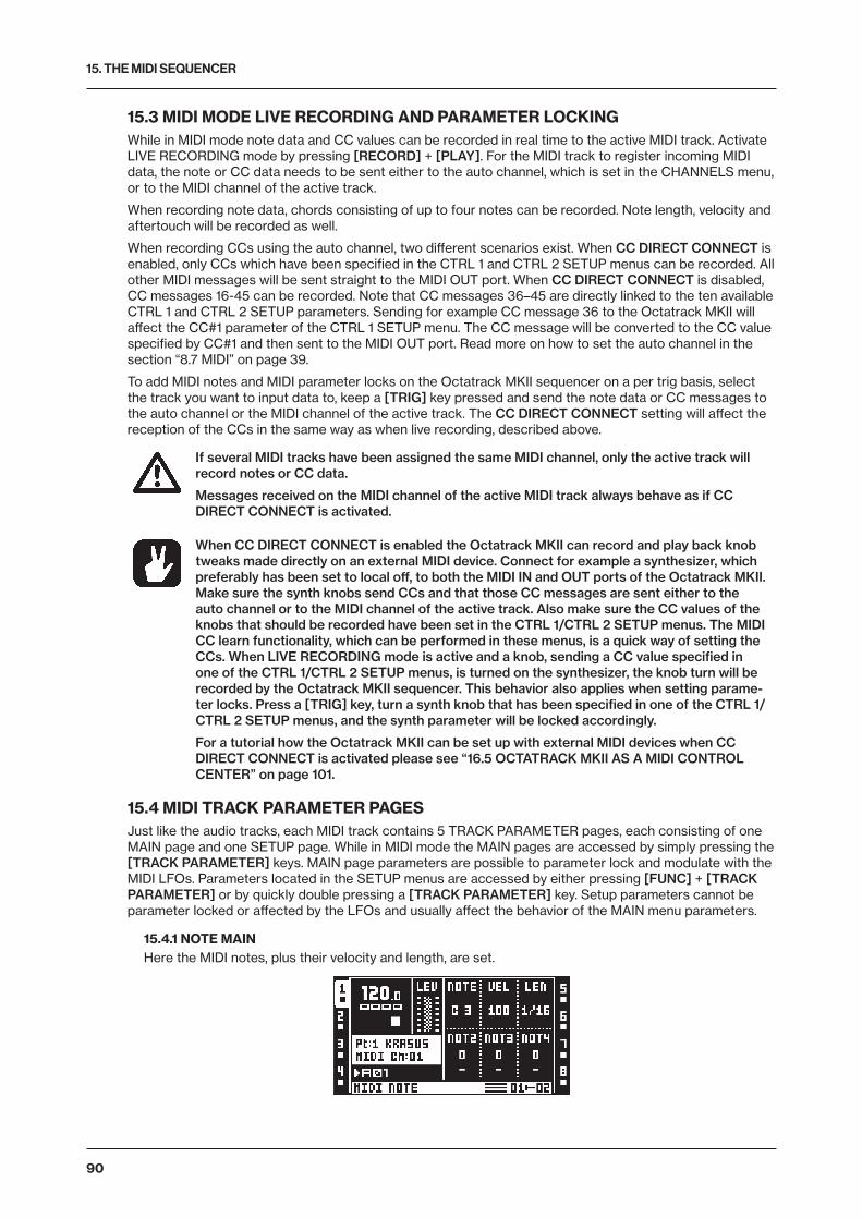
15. THE MIDI SEQUENCER
90
15.3 MIDI MODE LIVE RECORDING AND PARAMETER LOCKINGWhile in MIDI mode note data and CC values can be recorded in real time to the active MIDI track. Activate LIVE RECORDING mode by pressing [RECORD] + [PLAY]. For the MIDI track to register incoming MIDI data, the note or CC data needs to be sent either to the auto channel, which is set in the CHANNELS menu, or to the MIDI channel of the active track.
When recording note data, chords consisting of up to four notes can be recorded. Note length, velocity and aftertouch will be recorded as well.
When recording CCs using the auto channel, two different scenarios exist. When CC DIRECT CONNECT is enabled, only CCs which have been specified in the CTRL 1 and CTRL 2 SETUP menus can be recorded. All other MIDI messages will be sent straight to the MIDI OUT port. When CC DIRECT CONNECT is disabled, CC messages 16-45 can be recorded. Note that CC messages 36–45 are directly linked to the ten available CTRL 1 and CTRL 2 SETUP parameters. Sending for example CC message 36 to the Octatrack MKII will affect the CC#1 parameter of the CTRL 1 SETUP menu. The CC message will be converted to the CC value specified by CC#1 and then sent to the MIDI OUT port. Read more on how to set the auto channel in the section “8.7 MIDI” on page 39.
To add MIDI notes and MIDI parameter locks on the Octatrack MKII sequencer on a per trig basis, select the track you want to input data to, keep a [TRIG] key pressed and send the note data or CC messages to the auto channel or the MIDI channel of the active track. The CC DIRECT CONNECT setting will affect the reception of the CCs in the same way as when live recording, described above.
If several MIDI tracks have been assigned the same MIDI channel, only the active track will record notes or CC data.
Messages received on the MIDI channel of the active MIDI track always behave as if CC DIRECT CONNECT is activated.
When CC DIRECT CONNECT is enabled the Octatrack MKII can record and play back knob tweaks made directly on an external MIDI device. Connect for example a synthesizer, which preferably has been set to local off, to both the MIDI IN and OUT ports of the Octatrack MKII. Make sure the synth knobs send CCs and that those CC messages are sent either to the auto channel or to the MIDI channel of the active track. Also make sure the CC values of the knobs that should be recorded have been set in the CTRL 1/CTRL 2 SETUP menus. The MIDI CC learn functionality, which can be performed in these menus, is a quick way of setting the CCs. When LIVE RECORDING mode is active and a knob, sending a CC value specified in one of the CTRL 1/CTRL 2 SETUP menus, is turned on the synthesizer, the knob turn will be recorded by the Octatrack MKII sequencer. This behavior also applies when setting parame-ter locks. Press a [TRIG] key, turn a synth knob that has been specified in one of the CTRL 1/CTRL 2 SETUP menus, and the synth parameter will be locked accordingly.
For a tutorial how the Octatrack MKII can be set up with external MIDI devices when CC DIRECT CONNECT is activated please see “16.5 OCTATRACK MKII AS A MIDI CONTROL CENTER” on page 101.
15.4 MIDI TRACK PARAMETER PAGESJust like the audio tracks, each MIDI track contains 5 TRACK PARAMETER pages, each consisting of one MAIN page and one SETUP page. While in MIDI mode the MAIN pages are accessed by simply pressing the [TRACK PARAMETER] keys. MAIN page parameters are possible to parameter lock and modulate with the MIDI LFOs. Parameters located in the SETUP menus are accessed by either pressing [FUNC] + [TRACK PARAMETER] or by quickly double pressing a [TRACK PARAMETER] key. Setup parameters cannot be parameter locked or affected by the LFOs and usually affect the behavior of the MAIN menu parameters.
15.4.1 NOTE MAINHere the MIDI notes, plus their velocity and length, are set.
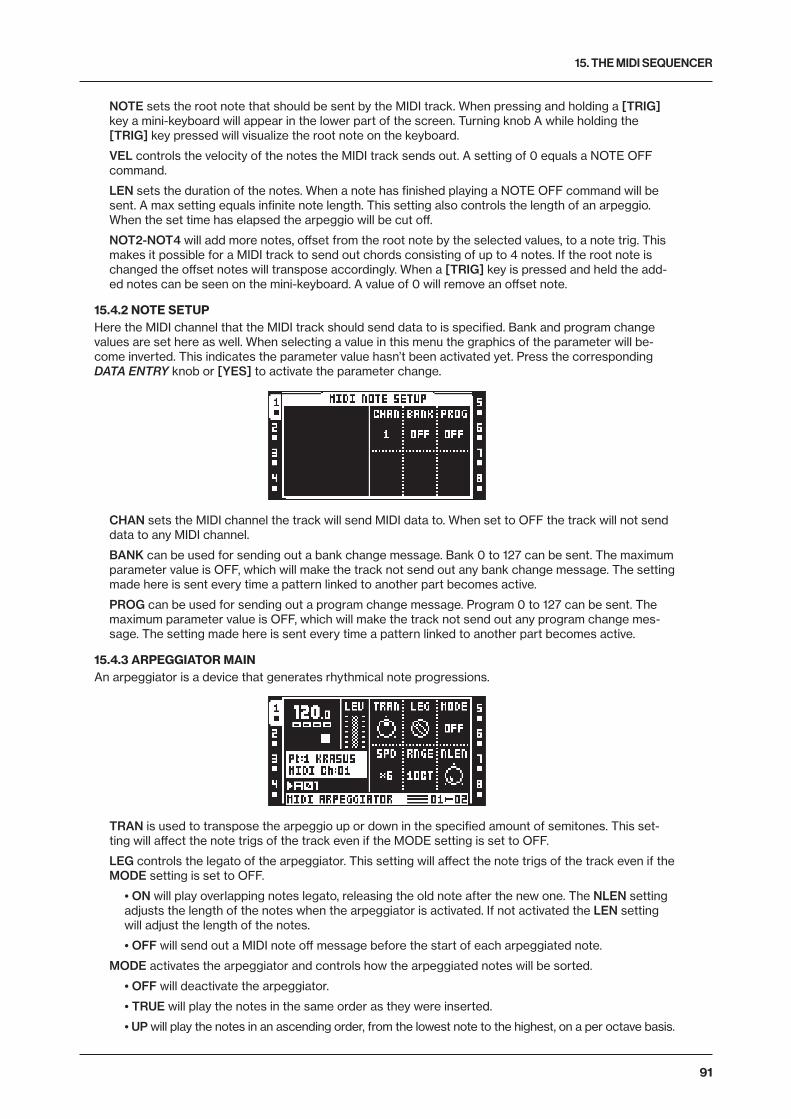
15. THE MIDI SEQUENCER
91
NOTE sets the root note that should be sent by the MIDI track. When pressing and holding a [TRIG] key a mini-keyboard will appear in the lower part of the screen. Turning knob A while holding the [TRIG] key pressed will visualize the root note on the keyboard.
VEL controls the velocity of the notes the MIDI track sends out. A setting of 0 equals a NOTE OFF command.
LEN sets the duration of the notes. When a note has finished playing a NOTE OFF command will be sent. A max setting equals infinite note length. This setting also controls the length of an arpeggio. When the set time has elapsed the arpeggio will be cut off.
NOT2-NOT4 will add more notes, offset from the root note by the selected values, to a note trig. This makes it possible for a MIDI track to send out chords consisting of up to 4 notes. If the root note is changed the offset notes will transpose accordingly. When a [TRIG] key is pressed and held the add-ed notes can be seen on the mini-keyboard. A value of 0 will remove an offset note.
15.4.2 NOTE SETUPHere the MIDI channel that the MIDI track should send data to is specified. Bank and program change values are set here as well. When selecting a value in this menu the graphics of the parameter will be-come inverted. This indicates the parameter value hasn’t been activated yet. Press the corresponding DATA ENTRY knob or [YES] to activate the parameter change.
CHAN sets the MIDI channel the track will send MIDI data to. When set to OFF the track will not send data to any MIDI channel.
BANK can be used for sending out a bank change message. Bank 0 to 127 can be sent. The maximum parameter value is OFF, which will make the track not send out any bank change message. The setting made here is sent every time a pattern linked to another part becomes active.
PROG can be used for sending out a program change message. Program 0 to 127 can be sent. The maximum parameter value is OFF, which will make the track not send out any program change mes-sage. The setting made here is sent every time a pattern linked to another part becomes active.
15.4.3 ARPEGGIATOR MAINAn arpeggiator is a device that generates rhythmical note progressions.
TRAN is used to transpose the arpeggio up or down in the specified amount of semitones. This set-ting will affect the note trigs of the track even if the MODE setting is set to OFF.
LEG controls the legato of the arpeggiator. This setting will affect the note trigs of the track even if the MODE setting is set to OFF.
• ON will play overlapping notes legato, releasing the old note after the new one. The NLEN setting adjusts the length of the notes when the arpeggiator is activated. If not activated the LEN setting will adjust the length of the notes.
• OFF will send out a MIDI note off message before the start of each arpeggiated note.
MODE activates the arpeggiator and controls how the arpeggiated notes will be sorted.
• OFF will deactivate the arpeggiator.
• TRUE will play the notes in the same order as they were inserted.
• UP will play the notes in an ascending order, from the lowest note to the highest, on a per octave basis.
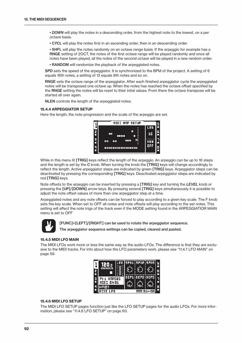
15. THE MIDI SEQUENCER
92
• DOWN will play the notes in a descending order, from the highest note to the lowest, on a per octave basis.
• CYCL will play the notes first in an ascending order, then in an descending order.
• SHFL will play the notes randomly on an octave range basis. If the arpeggio for example has a RNGE setting of 2OCT, the notes of the first octave range will be played randomly and once all notes have been played, all the notes of the second octave will be played in a new random order.
• RANDOM will randomize the playback of the arpeggiated notes.
SPD sets the speed of the arpeggiator. It is synchronized to the BPM of the project. A setting of 6 equals 16th notes, a setting of 12 equals 8th notes and so on.
RNGE sets the octave range of the arpeggiator. After each finished arpeggiator cycle the arpeggiated notes will be transposed one octave up. When the notes has reached the octave offset specified by the RNGE setting the notes will be reset to their inital values. From there the octave transpose will be started all over again.
NLEN controls the length of the arpeggiated notes.
15.4.4 ARPEGGIATOR SETUPHere the length, the note progression and the scale of the arpeggio are set.
While in this menu lit [TRIG] keys reflect the length of the arpeggio. An arpeggio can be up to 16 steps and the length is set by the C knob. When turning the knob the [TRIG] keys will change accordingly to reflect the length. Active arpeggiator steps are indicated by green [TRIG] keys. Arpeggiator steps can be deactivated by pressing the corresponding [TRIG] keys. Deactivated arpeggiator steps are indicated by red [TRIG] keys.
Note offsets to the arpeggio can be inserted by pressing a [TRIG] key and turning the LEVEL knob or pressing the [UP]/[DOWN] arrow keys. By pressing several [TRIG] keys simultaneously it is possible to adjust the note offset values of more than one arpeggiator step at a time.
Arpeggiated notes and any note offsets can be forced to play according to a given key scale. The F knob sets the key scale. When set to OFF all notes and note offsets will play according to the set notes. This setting will affect the note trigs of the track even if the MODE setting found in the ARPEGGIATIOR MAIN menu is set to OFF
[FUNC]+[LEFT]/[RIGHT] can be used to rotate the arpeggiator sequence.
The arpeggiator sequence settings can be copied, cleared and pasted.
15.4.5 MIDI LFO MAINThe MIDI LFOs work more or less the same way as the audio LFOs. The difference is that they are exclu-sive to the MIDI tracks. For info about how the LFO parameters work, please see “11.4.7 LFO MAIN” on page 59.
15.4.6 MIDI LFO SETUPThe MIDI LFO SETUP pages function just like the LFO SETUP pages for the audio LFOs. For more infor-mation, please see “11.4.8 LFO SETUP” on page 60.
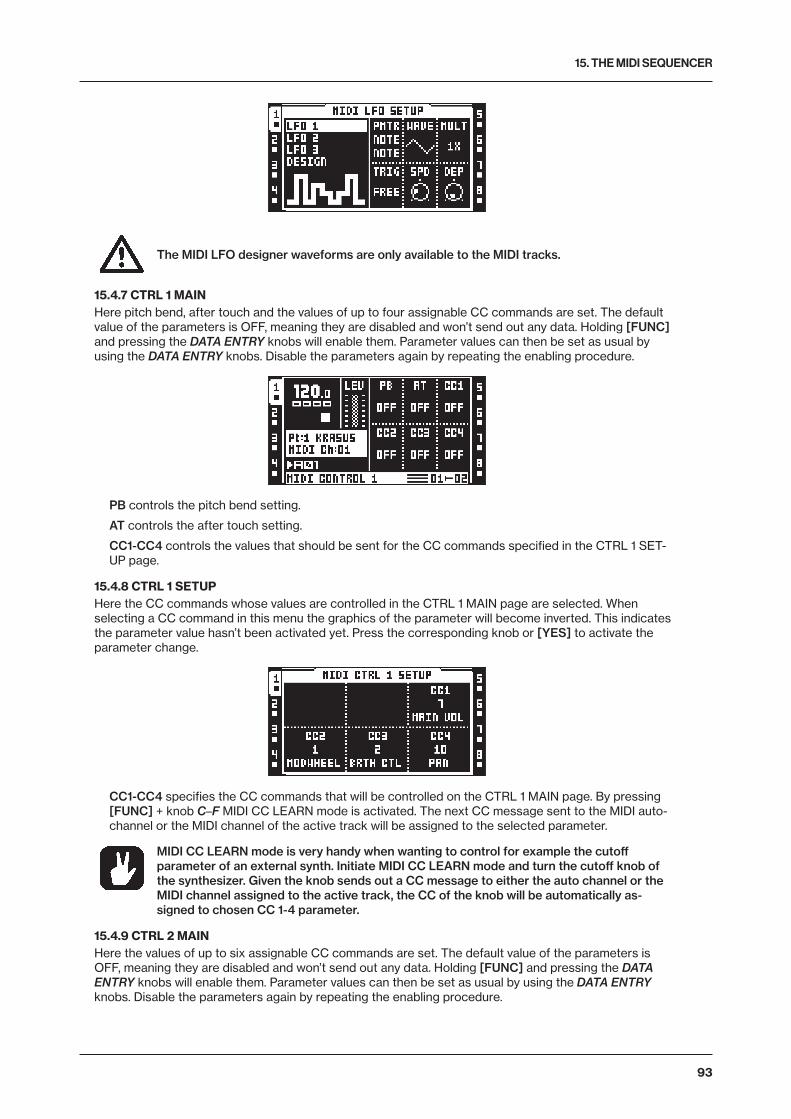
15. THE MIDI SEQUENCER
93
The MIDI LFO designer waveforms are only available to the MIDI tracks.
15.4.7 CTRL 1 MAINHere pitch bend, after touch and the values of up to four assignable CC commands are set. The default value of the parameters is OFF, meaning they are disabled and won’t send out any data. Holding [FUNC] and pressing the DATA ENTRY knobs will enable them. Parameter values can then be set as usual by using the DATA ENTRY knobs. Disable the parameters again by repeating the enabling procedure.
PB controls the pitch bend setting.
AT controls the after touch setting.
CC1-CC4 controls the values that should be sent for the CC commands specified in the CTRL 1 SET-UP page.
15.4.8 CTRL 1 SETUPHere the CC commands whose values are controlled in the CTRL 1 MAIN page are selected. When selecting a CC command in this menu the graphics of the parameter will become inverted. This indicates the parameter value hasn’t been activated yet. Press the corresponding knob or [YES] to activate the parameter change.
CC1-CC4 specifies the CC commands that will be controlled on the CTRL 1 MAIN page. By pressing [FUNC] + knob C–F MIDI CC LEARN mode is activated. The next CC message sent to the MIDI auto-channel or the MIDI channel of the active track will be assigned to the selected parameter.
MIDI CC LEARN mode is very handy when wanting to control for example the cutoff parameter of an external synth. Initiate MIDI CC LEARN mode and turn the cutoff knob of the synthesizer. Given the knob sends out a CC message to either the auto channel or the MIDI channel assigned to the active track, the CC of the knob will be automatically as-signed to chosen CC 1-4 parameter.
15.4.9 CTRL 2 MAINHere the values of up to six assignable CC commands are set. The default value of the parameters is OFF, meaning they are disabled and won’t send out any data. Holding [FUNC] and pressing the DATA ENTRY knobs will enable them. Parameter values can then be set as usual by using the DATA ENTRY knobs. Disable the parameters again by repeating the enabling procedure.
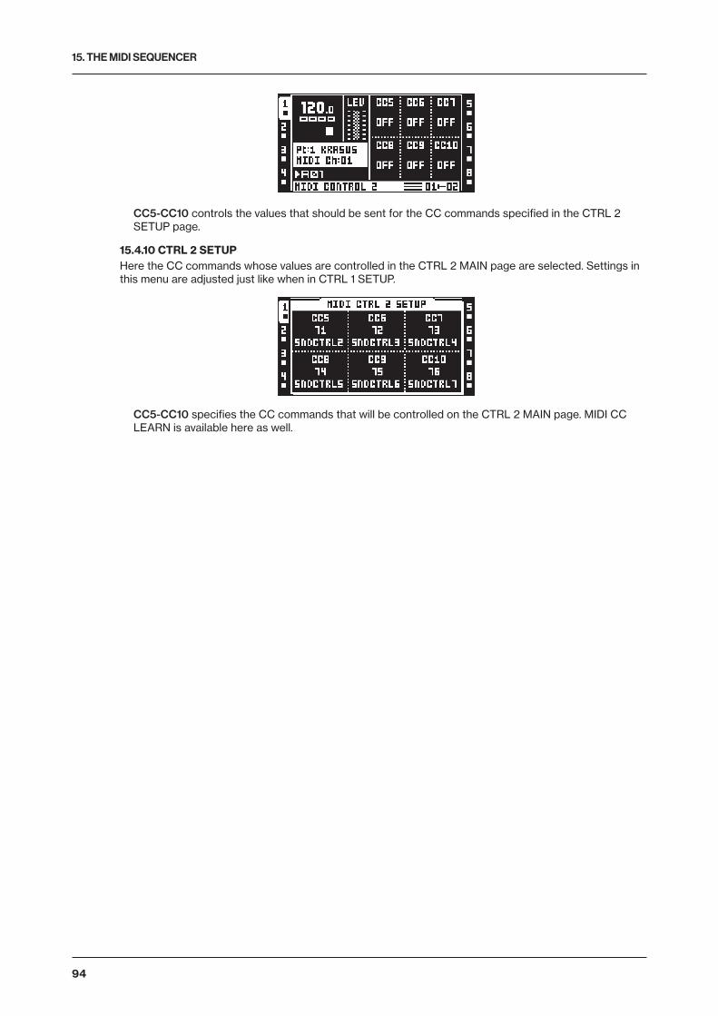
15. THE MIDI SEQUENCER
94
CC5-CC10 controls the values that should be sent for the CC commands specified in the CTRL 2 SETUP page.
15.4.10 CTRL 2 SETUPHere the CC commands whose values are controlled in the CTRL 2 MAIN page are selected. Settings in this menu are adjusted just like when in CTRL 1 SETUP.
CC5-CC10 specifies the CC commands that will be controlled on the CTRL 2 MAIN page. MIDI CC LEARN is available here as well.
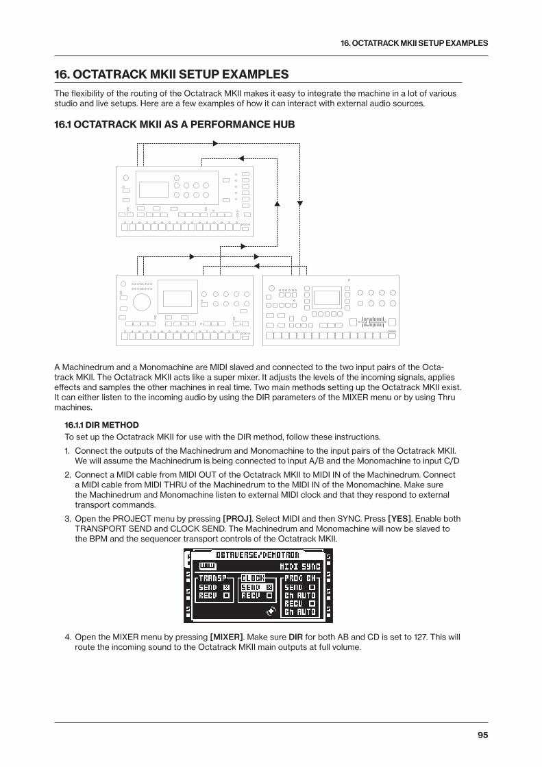
16. OCTATRACK MKII SETUP EXAMPLES
95
16. OCTATRACK MKII SETUP EXAMPLESThe flexibility of the routing of the Octatrack MKII makes it easy to integrate the machine in a lot of various studio and live setups. Here are a few examples of how it can interact with external audio sources.
16.1 OCTATRACK MKII AS A PERFORMANCE HUB
A Machinedrum and a Monomachine are MIDI slaved and connected to the two input pairs of the Octa-track MKII. The Octatrack MKII acts like a super mixer. It adjusts the levels of the incoming signals, applies effects and samples the other machines in real time. Two main methods setting up the Octatrack MKII exist. It can either listen to the incoming audio by using the DIR parameters of the MIXER menu or by using Thru machines.
16.1.1 DIR METHODTo set up the Octatrack MKII for use with the DIR method, follow these instructions.
1. Connect the outputs of the Machinedrum and Monomachine to the input pairs of the Octatrack MKII. We will assume the Machinedrum is being connected to input A/B and the Monomachine to input C/D
2. Connect a MIDI cable from MIDI OUT of the Octatrack MKII to MIDI IN of the Machinedrum. Connect a MIDI cable from MIDI THRU of the Machinedrum to the MIDI IN of the Monomachine. Make sure the Machinedrum and Monomachine listen to external MIDI clock and that they respond to external transport commands.
3. Open the PROJECT menu by pressing [PROJ]. Select MIDI and then SYNC. Press [YES]. Enable both TRANSPORT SEND and CLOCK SEND. The Machinedrum and Monomachine will now be slaved to the BPM and the sequencer transport controls of the Octatrack MKII.
4. Open the MIXER menu by pressing [MIXER]. Make sure DIR for both AB and CD is set to 127. This will route the incoming sound to the Octatrack MKII main outputs at full volume.
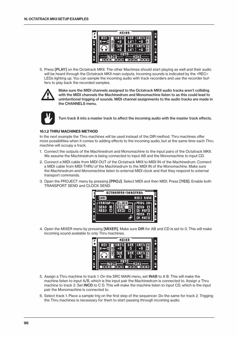
16. OCTATRACK MKII SETUP EXAMPLES
96
5. Press [PLAY] on the Octatrack MKII. The other Machines should start playing as well and their audio will be heard through the Octatrack MKII main outputs. Incoming sounds is indicated by the <REC> LEDs lighting up. You can sample the incoming audio with track recorders and use the recorder buf-fers to play back the recorded samples.
Make sure the MIDI channels assigned to the Octatrack MKII audio tracks aren’t colliding with the MIDI channels the Machinedrum and Monomachine listen to as this could lead to unintentional trigging of sounds. MIDI channel assignments to the audio tracks are made in the CHANNELS menu.
Turn track 8 into a master track to affect the incoming audio with the master track effects.
16.1.2 THRU MACHINES METHODIn the next example the Thru machines will be used instead of the DIR method. Thru machines offer more possibilities when it comes to adding effects to the incoming audio, but at the same time each Thru machine will occupy a track.
1. Connect the outputs of the Machinedrum and Monomachine to the input pairs of the Octatrack MKII. We assume the Machinedrum is being connected to input AB and the Monomachine to input CD.
2. Connect a MIDI cable from MIDI OUT of the Octatrack MKII to MIDI IN of the Machinedrum. Connect a MIDI cable from MIDI THRU of the Machinedrum to the MIDI IN of the Monomachine. Make sure the Machinedrum and Monomachine listen to external MIDI clock and that they respond to external transport commands.
3. Open the PROJECT menu by pressing [PROJ]. Select MIDI and then MIDI. Press [YES]. Enable both TRANSPORT SEND and CLOCK SEND.
4. Open the MIXER menu by pressing [MIXER]. Make sure DIR for AB and CD is set to 0. This will make incoming sound available to only Thru machines.
5. Assign a Thru machine to track 1. On the SRC MAIN menu, set INAB to A B. This will make the machine listen to input A/B, which is the input pair the Machinedrum is connected to. Assign a Thru machine to track 2. Set INCD to C D. This will make the machine listen to input CD, which is the input pair the Monomachine is connected to.
6. Select track 1. Place a sample trig on the first step of the sequencer. Do the same for track 2. Trigging the Thru machines is necessary for them to start passing through incoming audio.
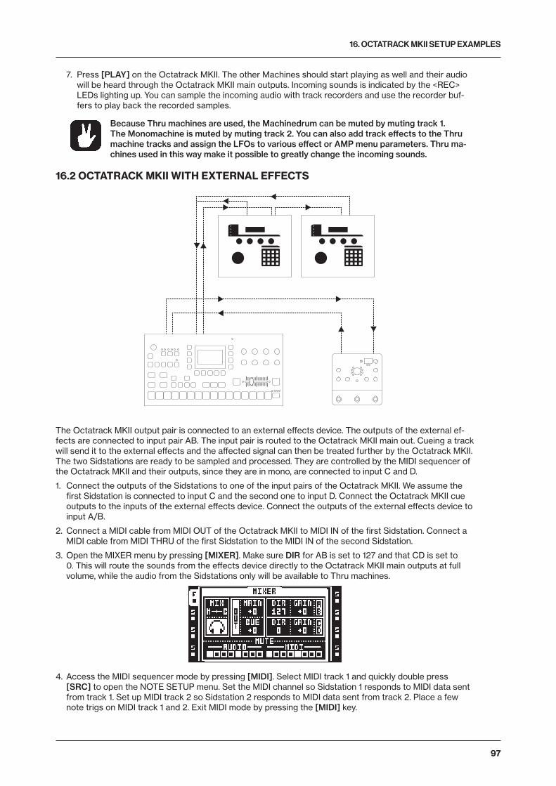
16. OCTATRACK MKII SETUP EXAMPLES
97
7. Press [PLAY] on the Octatrack MKII. The other Machines should start playing as well and their audio will be heard through the Octatrack MKII main outputs. Incoming sounds is indicated by the <REC> LEDs lighting up. You can sample the incoming audio with track recorders and use the recorder buf-fers to play back the recorded samples.
Because Thru machines are used, the Machinedrum can be muted by muting track 1. The Monomachine is muted by muting track 2. You can also add track effects to the Thru machine tracks and assign the LFOs to various effect or AMP menu parameters. Thru ma-chines used in this way make it possible to greatly change the incoming sounds.
16.2 OCTATRACK MKII WITH EXTERNAL EFFECTS
The Octatrack MKII output pair is connected to an external effects device. The outputs of the external ef-fects are connected to input pair AB. The input pair is routed to the Octatrack MKII main out. Cueing a track will send it to the external effects and the affected signal can then be treated further by the Octatrack MKII. The two Sidstations are ready to be sampled and processed. They are controlled by the MIDI sequencer of the Octatrack MKII and their outputs, since they are in mono, are connected to input C and D.
1. Connect the outputs of the Sidstations to one of the input pairs of the Octatrack MKII. We assume the first Sidstation is connected to input C and the second one to input D. Connect the Octatrack MKII cue outputs to the inputs of the external effects device. Connect the outputs of the external effects device to input A/B.
2. Connect a MIDI cable from MIDI OUT of the Octatrack MKII to MIDI IN of the first Sidstation. Connect a MIDI cable from MIDI THRU of the first Sidstation to the MIDI IN of the second Sidstation.
3. Open the MIXER menu by pressing [MIXER]. Make sure DIR for AB is set to 127 and that CD is set to 0. This will route the sounds from the effects device directly to the Octatrack MKII main outputs at full volume, while the audio from the Sidstations only will be available to Thru machines.
4. Access the MIDI sequencer mode by pressing [MIDI]. Select MIDI track 1 and quickly double press [SRC] to open the NOTE SETUP menu. Set the MIDI channel so Sidstation 1 responds to MIDI data sent from track 1. Set up MIDI track 2 so Sidstation 2 responds to MIDI data sent from track 2. Place a few note trigs on MIDI track 1 and 2. Exit MIDI mode by pressing the [MIDI] key.
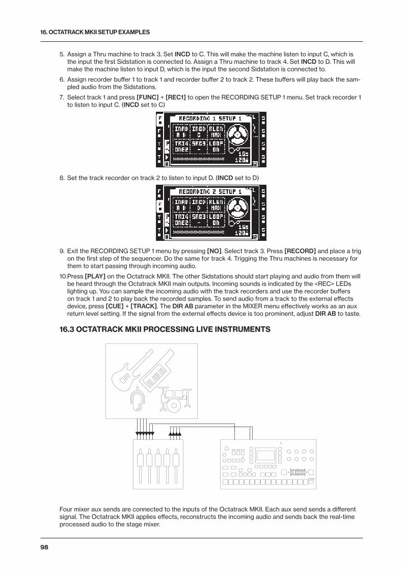
16. OCTATRACK MKII SETUP EXAMPLES
98
5. Assign a Thru machine to track 3. Set INCD to C. This will make the machine listen to input C, which is the input the first Sidstation is connected to. Assign a Thru machine to track 4. Set INCD to D. This will make the machine listen to input D, which is the input the second Sidstation is connected to.
6. Assign recorder buffer 1 to track 1 and recorder buffer 2 to track 2. These buffers will play back the sam-pled audio from the Sidstations.
7. Select track 1 and press [FUNC] + [REC1] to open the RECORDING SETUP 1 menu. Set track recorder 1 to listen to input C. (INCD set to C)
8. Set the track recorder on track 2 to listen to input D. (INCD set to D)
9. Exit the RECORDING SETUP 1 menu by pressing [NO]. Select track 3. Press [RECORD] and place a trig on the first step of the sequencer. Do the same for track 4. Trigging the Thru machines is necessary for them to start passing through incoming audio.
10. Press [PLAY] on the Octatrack MKII. The other Sidstations should start playing and audio from them will be heard through the Octatrack MKII main outputs. Incoming sounds is indicated by the <REC> LEDs lighting up. You can sample the incoming audio with the track recorders and use the recorder buffers on track 1 and 2 to play back the recorded samples. To send audio from a track to the external effects device, press [CUE] + [TRACK]. The DIR AB parameter in the MIXER menu effectively works as an aux return level setting. If the signal from the external effects device is too prominent, adjust DIR AB to taste.
16.3 OCTATRACK MKII PROCESSING LIVE INSTRUMENTS
Four mixer aux sends are connected to the inputs of the Octatrack MKII. Each aux send sends a different signal. The Octatrack MKII applies effects, reconstructs the incoming audio and sends back the real-time processed audio to the stage mixer.

16. OCTATRACK MKII SETUP EXAMPLES
99
1. Connect four aux sends from the mixer to the four inputs of the Octatrack MKII. The guitar is being sent to input A, the bass to input B, the synth to input C and the vocals to input D. Connect the Octatrack MKII main outputs to the mixer.
2. Open the MIXER menu by pressing [MIXER]. Make sure DIR for both AB and CD is set to 0. This will stop the incoming sound from being sent to the Octatrack MKII main outputs.
3. Press [CUE] + [REC1] and [CUE] + [REC2] to route the incoming audio directly to the cue outputs. Cueing like this will prevent the incoming audio from being sent to the main outputs. This is necessary as only the sampled and processed audio should be sent back to the stage mixer. If the incoming audio were directly routed to the main Octatrack MKII outputs and hence back to the stage mixer, phasing issues might occur.
4. Select track 1 by pressing the first [TRACK] key. Open the RECORDING SETUP 1 menu for track 1 by pressing [FUNC] + [REC1]. Set INAB to A. When [TRACK] key 1 + [REC1] are pressed, the track record-er will start recording the guitar. Repeat the procedure for track 2, but set INAB to B. This will record the bass guitar. Likewise, set up track recorders 3 and 4 so the synth and the vocals can be sampled and processed.
5. Assign recorder buffer 1 to track 1. Assign recorder buffer 2 to track 2. Do likewise for tracks 3 and 4. Now guitar, bass, synth and vocals can be sampled and immediately played back.
You can now listen to the incoming sounds using a pair of headphones connected to the Octatrack MKII headphones output. The incoming sounds will not be heard on the main outputs as they are cued. Once you have sampled the sounds and applied effects, parameter locks etc, they can be played back by the recorder buffers which are routed to the Octatrack MKII main outputs. The processed audio will thus be sent to the stage mixer and mixed with the other sounds.
16.4 OCTATRACK MKII AS A DJ MIXER AND SAMPLER
Two DJ decks are connected to the Octatrack MKII inputs. The headphones output is set to monitor both the main and cue outputs. The crossfader is assigned to control the main output balance between the two incoming signals. The Octatrack MKII can mix between the DJ decks by either using the DIR method or the Thru machines method.
16.4.1 DJ MIXING USING THE DIR METHOD1. Connect the first DJ deck to Octatrack MKII input pair AB. Connect the second DJ deck to input pair CD.
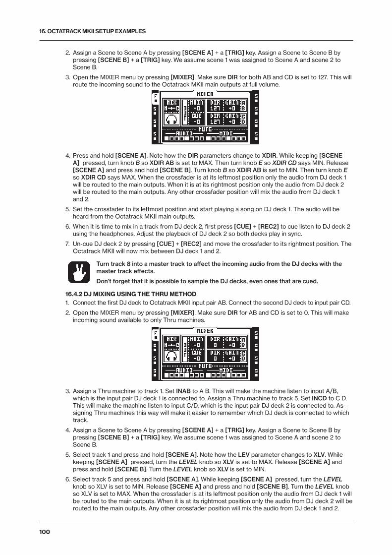
16. OCTATRACK MKII SETUP EXAMPLES
100
2. Assign a Scene to Scene A by pressing [SCENE A] + a [TRIG] key. Assign a Scene to Scene B by pressing [SCENE B] + a [TRIG] key. We assume scene 1 was assigned to Scene A and scene 2 to Scene B.
3. Open the MIXER menu by pressing [MIXER]. Make sure DIR for both AB and CD is set to 127. This will route the incoming sound to the Octatrack MKII main outputs at full volume.
4. Press and hold [SCENE A]. Note how the DIR parameters change to XDIR. While keeping [SCENE A] pressed, turn knob B so XDIR AB is set to MAX. Then turn knob E so XDIR CD says MIN. Release [SCENE A] and press and hold [SCENE B]. Turn knob B so XDIR AB is set to MIN. Then turn knob E so XDIR CD says MAX. When the crossfader is at its leftmost position only the audio from DJ deck 1 will be routed to the main outputs. When it is at its rightmost position only the audio from DJ deck 2 will be routed to the main outputs. Any other crossfader position will mix the audio from DJ deck 1 and 2.
5. Set the crossfader to its leftmost position and start playing a song on DJ deck 1. The audio will be heard from the Octatrack MKII main outputs.
6. When it is time to mix in a track from DJ deck 2, first press [CUE] + [REC2] to cue listen to DJ deck 2 using the headphones. Adjust the playback of DJ deck 2 so both decks play in sync.
7. Un-cue DJ deck 2 by pressing [CUE] + [REC2] and move the crossfader to its rightmost position. The Octatrack MKII will now mix between DJ deck 1 and 2.
Turn track 8 into a master track to affect the incoming audio from the DJ decks with the master track effects.
Don’t forget that it is possible to sample the DJ decks, even ones that are cued.
16.4.2 DJ MIXING USING THE THRU METHOD1. Connect the first DJ deck to Octatrack MKII input pair AB. Connect the second DJ deck to input pair CD.
2. Open the MIXER menu by pressing [MIXER]. Make sure DIR for AB and CD is set to 0. This will make incoming sound available to only Thru machines.
3. Assign a Thru machine to track 1. Set INAB to A B. This will make the machine listen to input A/B, which is the input pair DJ deck 1 is connected to. Assign a Thru machine to track 5. Set INCD to C D. This will make the machine listen to input C/D, which is the input pair DJ deck 2 is connected to. As-signing Thru machines this way will make it easier to remember which DJ deck is connected to which track.
4. Assign a Scene to Scene A by pressing [SCENE A] + a [TRIG] key. Assign a Scene to Scene B by pressing [SCENE B] + a [TRIG] key. We assume scene 1 was assigned to Scene A and scene 2 to Scene B.
5. Select track 1 and press and hold [SCENE A]. Note how the LEV parameter changes to XLV. While keeping [SCENE A] pressed, turn the LEVEL knob so XLV is set to MAX. Release [SCENE A] and press and hold [SCENE B]. Turn the LEVEL knob so XLV is set to MIN.
6. Select track 5 and press and hold [SCENE A]. While keeping [SCENE A] pressed, turn the LEVEL knob so XLV is set to MIN. Release [SCENE A] and press and hold [SCENE B]. Turn the LEVEL knob so XLV is set to MAX. When the crossfader is at its leftmost position only the audio from DJ deck 1 will be routed to the main outputs. When it is at its rightmost position only the audio from DJ deck 2 will be routed to the main outputs. Any other crossfader position will mix the audio from DJ deck 1 and 2.
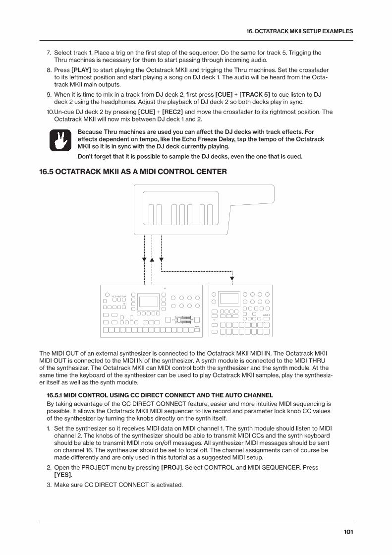
16. OCTATRACK MKII SETUP EXAMPLES
101
7. Select track 1. Place a trig on the first step of the sequencer. Do the same for track 5. Trigging the Thru machines is necessary for them to start passing through incoming audio.
8. Press [PLAY] to start playing the Octatrack MKII and trigging the Thru machines. Set the crossfader to its leftmost position and start playing a song on DJ deck 1. The audio will be heard from the Octa-track MKII main outputs.
9. When it is time to mix in a track from DJ deck 2, first press [CUE] + [TRACK 5] to cue listen to DJ deck 2 using the headphones. Adjust the playback of DJ deck 2 so both decks play in sync.
10. Un-cue DJ deck 2 by pressing [CUE] + [REC2] and move the crossfader to its rightmost position. The Octatrack MKII will now mix between DJ deck 1 and 2.
Because Thru machines are used you can affect the DJ decks with track effects. For effects dependent on tempo, like the Echo Freeze Delay, tap the tempo of the Octatrack MKII so it is in sync with the DJ deck currently playing.
Don’t forget that it is possible to sample the DJ decks, even the one that is cued.
16.5 OCTATRACK MKII AS A MIDI CONTROL CENTER
The MIDI OUT of an external synthesizer is connected to the Octatrack MKII MIDI IN. The Octatrack MKII MIDI OUT is connected to the MIDI IN of the synthesizer. A synth module is connected to the MIDI THRU of the synthesizer. The Octatrack MKII can MIDI control both the synthesizer and the synth module. At the same time the keyboard of the synthesizer can be used to play Octatrack MKII samples, play the synthesiz-er itself as well as the synth module.
16.5.1 MIDI CONTROL USING CC DIRECT CONNECT AND THE AUTO CHANNELBy taking advantage of the CC DIRECT CONNECT feature, easier and more intuitive MIDI sequencing is possible. It allows the Octatrack MKII MIDI sequencer to live record and parameter lock knob CC values of the synthesizer by turning the knobs directly on the synth itself.
1. Set the synthesizer so it receives MIDI data on MIDI channel 1. The synth module should listen to MIDI channel 2. The knobs of the synthesizer should be able to transmit MIDI CCs and the synth keyboard should be able to transmit MIDI note on/off messages. All synthesizer MIDI messages should be sent on channel 16. The synthesizer should be set to local off. The channel assignments can of course be made differently and are only used in this tutorial as a suggested MIDI setup.
2. Open the PROJECT menu by pressing [PROJ]. Select CONTROL and MIDI SEQUENCER. Press [YES].
3. Make sure CC DIRECT CONNECT is activated.
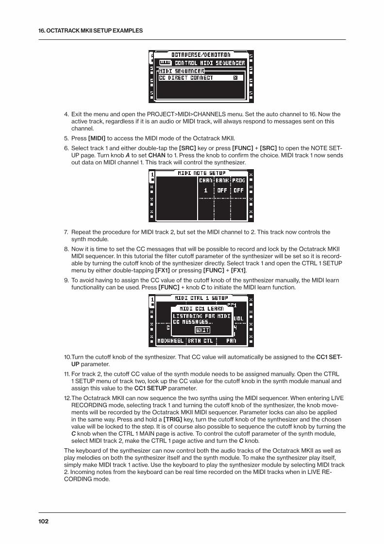
16. OCTATRACK MKII SETUP EXAMPLES
102
4. Exit the menu and open the PROJECT>MIDI>CHANNELS menu. Set the auto channel to 16. Now the active track, regardless if it is an audio or MIDI track, will always respond to messages sent on this channel.
5. Press [MIDI] to access the MIDI mode of the Octatrack MKII.
6. Select track 1 and either double-tap the [SRC] key or press [FUNC] + [SRC] to open the NOTE SET-UP page. Turn knob A to set CHAN to 1. Press the knob to confirm the choice. MIDI track 1 now sends out data on MIDI channel 1. This track will control the synthesizer.
7. Repeat the procedure for MIDI track 2, but set the MIDI channel to 2. This track now controls the synth module.
8. Now it is time to set the CC messages that will be possible to record and lock by the Octatrack MKII MIDI sequencer. In this tutorial the filter cutoff parameter of the synthesizer will be set so it is record-able by turning the cutoff knob of the synthesizer directly. Select track 1 and open the CTRL 1 SETUP menu by either double-tapping [FX1] or pressing [FUNC] + [FX1].
9. To avoid having to assign the CC value of the cutoff knob of the synthesizer manually, the MIDI learn functionality can be used. Press [FUNC] + knob C to initiate the MIDI learn function.
10. Turn the cutoff knob of the synthesizer. That CC value will automatically be assigned to the CC1 SET-UP parameter.
11. For track 2, the cutoff CC value of the synth module needs to be assigned manually. Open the CTRL 1 SETUP menu of track two, look up the CC value for the cutoff knob in the synth module manual and assign this value to the CC1 SETUP parameter.
12. The Octatrack MKII can now sequence the two synths using the MIDI sequencer. When entering LIVE RECORDING mode, selecting track 1 and turning the cutoff knob of the synthesizer, the knob move-ments will be recorded by the Octatrack MKII MIDI sequencer. Parameter locks can also be applied in the same way. Press and hold a [TRIG] key, turn the cutoff knob of the synthesizer and the chosen value will be locked to the step. It is of course also possible to sequence the cutoff knob by turning the C knob when the CTRL 1 MAIN page is active. To control the cutoff parameter of the synth module, select MIDI track 2, make the CTRL 1 page active and turn the C knob.
The keyboard of the synthesizer can now control both the audio tracks of the Octatrack MKII as well as play melodies on both the synthesizer itself and the synth module. To make the synthesizer play itself, simply make MIDI track 1 active. Use the keyboard to play the synthesizer module by selecting MIDI track 2. Incoming notes from the keyboard can be real time recorded on the MIDI tracks when in LIVE RE-CORDING mode.
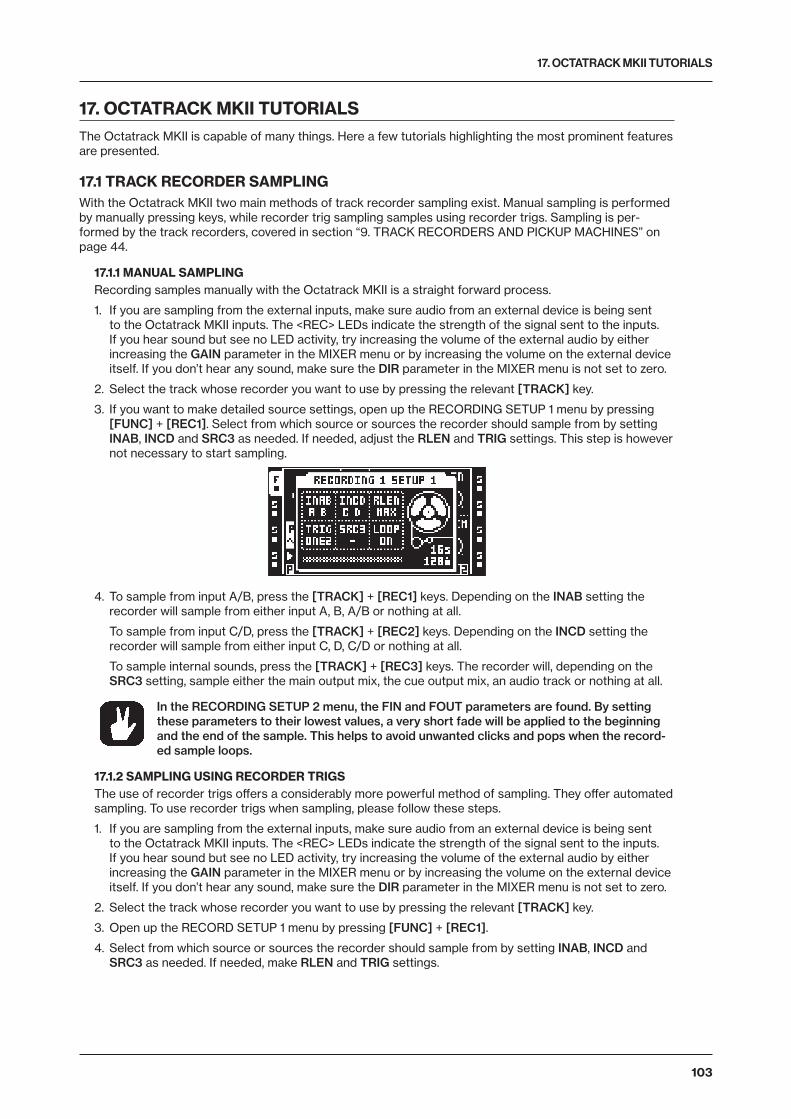
17. OCTATRACK MKII TUTORIALS
103
17. OCTATRACK MKII TUTORIALSThe Octatrack MKII is capable of many things. Here a few tutorials highlighting the most prominent features are presented.
17.1 TRACK RECORDER SAMPLINGWith the Octatrack MKII two main methods of track recorder sampling exist. Manual sampling is performed by manually pressing keys, while recorder trig sampling samples using recorder trigs. Sampling is per-formed by the track recorders, covered in section “9. TRACK RECORDERS AND PICKUP MACHINES” on page 44.
17.1.1 MANUAL SAMPLINGRecording samples manually with the Octatrack MKII is a straight forward process.
1. If you are sampling from the external inputs, make sure audio from an external device is being sent to the Octatrack MKII inputs. The <REC> LEDs indicate the strength of the signal sent to the inputs. If you hear sound but see no LED activity, try increasing the volume of the external audio by either increasing the GAIN parameter in the MIXER menu or by increasing the volume on the external device itself. If you don’t hear any sound, make sure the DIR parameter in the MIXER menu is not set to zero.
2. Select the track whose recorder you want to use by pressing the relevant [TRACK] key.
3. If you want to make detailed source settings, open up the RECORDING SETUP 1 menu by pressing [FUNC] + [REC1]. Select from which source or sources the recorder should sample from by setting INAB, INCD and SRC3 as needed. If needed, adjust the RLEN and TRIG settings. This step is however not necessary to start sampling.
4. To sample from input A/B, press the [TRACK] + [REC1] keys. Depending on the INAB setting the recorder will sample from either input A, B, A/B or nothing at all.
To sample from input C/D, press the [TRACK] + [REC2] keys. Depending on the INCD setting the recorder will sample from either input C, D, C/D or nothing at all.
To sample internal sounds, press the [TRACK] + [REC3] keys. The recorder will, depending on the SRC3 setting, sample either the main output mix, the cue output mix, an audio track or nothing at all.
In the RECORDING SETUP 2 menu, the FIN and FOUT parameters are found. By setting these parameters to their lowest values, a very short fade will be applied to the beginning and the end of the sample. This helps to avoid unwanted clicks and pops when the record-ed sample loops.
17.1.2 SAMPLING USING RECORDER TRIGSThe use of recorder trigs offers a considerably more powerful method of sampling. They offer automated sampling. To use recorder trigs when sampling, please follow these steps.
1. If you are sampling from the external inputs, make sure audio from an external device is being sent to the Octatrack MKII inputs. The <REC> LEDs indicate the strength of the signal sent to the inputs. If you hear sound but see no LED activity, try increasing the volume of the external audio by either increasing the GAIN parameter in the MIXER menu or by increasing the volume on the external device itself. If you don’t hear any sound, make sure the DIR parameter in the MIXER menu is not set to zero.
2. Select the track whose recorder you want to use by pressing the relevant [TRACK] key.
3. Open up the RECORD SETUP 1 menu by pressing [FUNC] + [REC1].
4. Select from which source or sources the recorder should sample from by setting INAB, INCD and SRC3 as needed. If needed, make RLEN and TRIG settings.
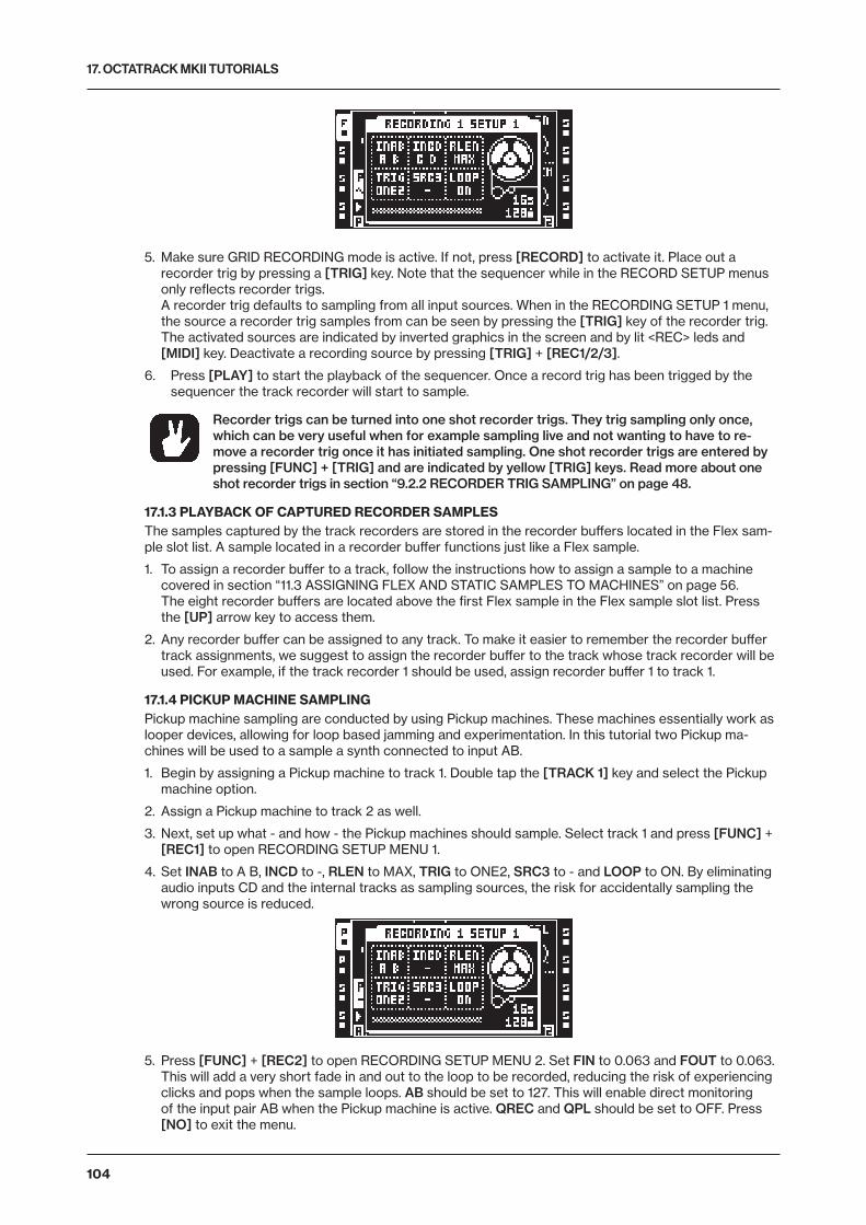
17. OCTATRACK MKII TUTORIALS
104
5. Make sure GRID RECORDING mode is active. If not, press [RECORD] to activate it. Place out a recorder trig by pressing a [TRIG] key. Note that the sequencer while in the RECORD SETUP menus only reflects recorder trigs. A recorder trig defaults to sampling from all input sources. When in the RECORDING SETUP 1 menu, the source a recorder trig samples from can be seen by pressing the [TRIG] key of the recorder trig. The activated sources are indicated by inverted graphics in the screen and by lit <REC> leds and [MIDI] key. Deactivate a recording source by pressing [TRIG] + [REC1/2/3].
6. Press [PLAY] to start the playback of the sequencer. Once a record trig has been trigged by the sequencer the track recorder will start to sample.
Recorder trigs can be turned into one shot recorder trigs. They trig sampling only once, which can be very useful when for example sampling live and not wanting to have to re-move a recorder trig once it has initiated sampling. One shot recorder trigs are entered by pressing [FUNC] + [TRIG] and are indicated by yellow [TRIG] keys. Read more about one shot recorder trigs in section “9.2.2 RECORDER TRIG SAMPLING” on page 48.
17.1.3 PLAYBACK OF CAPTURED RECORDER SAMPLESThe samples captured by the track recorders are stored in the recorder buffers located in the Flex sam-ple slot list. A sample located in a recorder buffer functions just like a Flex sample.
1. To assign a recorder buffer to a track, follow the instructions how to assign a sample to a machine covered in section “11.3 ASSIGNING FLEX AND STATIC SAMPLES TO MACHINES” on page 56. The eight recorder buffers are located above the first Flex sample in the Flex sample slot list. Press the [UP] arrow key to access them.
2. Any recorder buffer can be assigned to any track. To make it easier to remember the recorder buffer track assignments, we suggest to assign the recorder buffer to the track whose track recorder will be used. For example, if the track recorder 1 should be used, assign recorder buffer 1 to track 1.
17.1.4 PICKUP MACHINE SAMPLINGPickup machine sampling are conducted by using Pickup machines. These machines essentially work as looper devices, allowing for loop based jamming and experimentation. In this tutorial two Pickup ma-chines will be used to a sample a synth connected to input AB.
1. Begin by assigning a Pickup machine to track 1. Double tap the [TRACK 1] key and select the Pickup machine option.
2. Assign a Pickup machine to track 2 as well.
3. Next, set up what - and how - the Pickup machines should sample. Select track 1 and press [FUNC] + [REC1] to open RECORDING SETUP MENU 1.
4. Set INAB to A B, INCD to -, RLEN to MAX, TRIG to ONE2, SRC3 to - and LOOP to ON. By eliminating audio inputs CD and the internal tracks as sampling sources, the risk for accidentally sampling the wrong source is reduced.
5. Press [FUNC] + [REC2] to open RECORDING SETUP MENU 2. Set FIN to 0.063 and FOUT to 0.063. This will add a very short fade in and out to the loop to be recorded, reducing the risk of experiencing clicks and pops when the sample loops. AB should be set to 127. This will enable direct monitoring of the input pair AB when the Pickup machine is active. QREC and QPL should be set to OFF. Press [NO] to exit the menu.
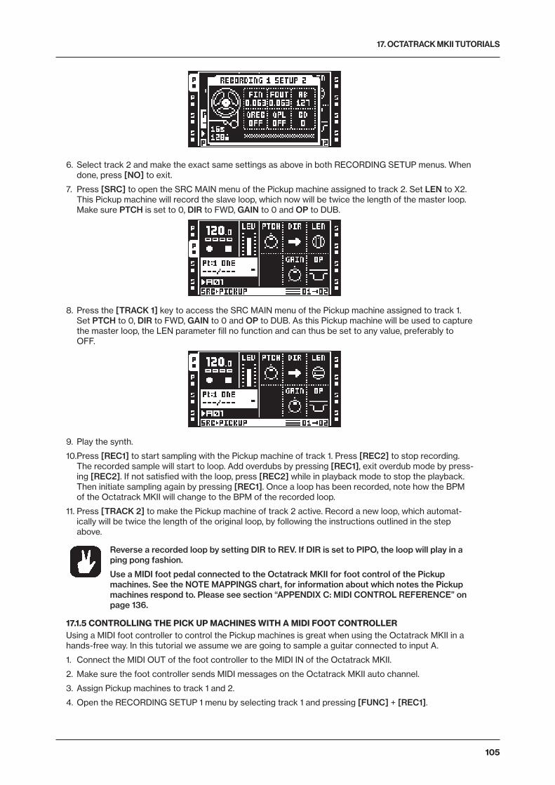
17. OCTATRACK MKII TUTORIALS
105
6. Select track 2 and make the exact same settings as above in both RECORDING SETUP menus. When done, press [NO] to exit.
7. Press [SRC] to open the SRC MAIN menu of the Pickup machine assigned to track 2. Set LEN to X2. This Pickup machine will record the slave loop, which now will be twice the length of the master loop. Make sure PTCH is set to 0, DIR to FWD, GAIN to 0 and OP to DUB.
8. Press the [TRACK 1] key to access the SRC MAIN menu of the Pickup machine assigned to track 1. Set PTCH to 0, DIR to FWD, GAIN to 0 and OP to DUB. As this Pickup machine will be used to capture the master loop, the LEN parameter fill no function and can thus be set to any value, preferably to OFF.
9. Play the synth.
10. Press [REC1] to start sampling with the Pickup machine of track 1. Press [REC2] to stop recording. The recorded sample will start to loop. Add overdubs by pressing [REC1], exit overdub mode by press-ing [REC2]. If not satisfied with the loop, press [REC2] while in playback mode to stop the playback. Then initiate sampling again by pressing [REC1]. Once a loop has been recorded, note how the BPM of the Octatrack MKII will change to the BPM of the recorded loop.
11. Press [TRACK 2] to make the Pickup machine of track 2 active. Record a new loop, which automat-ically will be twice the length of the original loop, by following the instructions outlined in the step above.
Reverse a recorded loop by setting DIR to REV. If DIR is set to PIPO, the loop will play in a ping pong fashion.
Use a MIDI foot pedal connected to the Octatrack MKII for foot control of the Pickup machines. See the NOTE MAPPINGS chart, for information about which notes the Pickup machines respond to. Please see section “APPENDIX C: MIDI CONTROL REFERENCE” on page 136.
17.1.5 CONTROLLING THE PICK UP MACHINES WITH A MIDI FOOT CONTROLLERUsing a MIDI foot controller to control the Pickup machines is great when using the Octatrack MKII in a hands-free way. In this tutorial we assume we are going to sample a guitar connected to input A.
1. Connect the MIDI OUT of the foot controller to the MIDI IN of the Octatrack MKII.
2. Make sure the foot controller sends MIDI messages on the Octatrack MKII auto channel.
3. Assign Pickup machines to track 1 and 2.
4. Open the RECORDING SETUP 1 menu by selecting track 1 and pressing [FUNC] + [REC1].
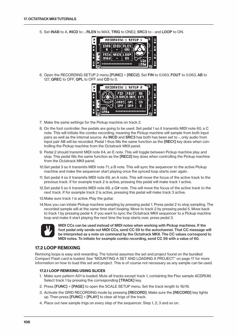
17. OCTATRACK MKII TUTORIALS
106
5. Set INAB to A, INCD to -, RLEN to MAX, TRIG to ONE2, SRC3 to - and LOOP to ON.
6. Open the RECORDING SETUP 2 menu [FUNC] + [REC2]. Set FIN to 0.063, FOUT to 0.063, AB to 127, QREC to OFF, QPL to OFF and CD to 0.
7. Make the same settings for the Pickup machine on track 2.
8. On the foot controller, five pedals are going to be used. Set pedal 1 so it transmits MIDI note 60, a C note. This will initiate the combo recording, meaning the Pickup machine will sample from both input pairs as well as the internal source. As INCD and SRC3 has both has been set to -, only audio from input pair AB will be recorded. Pedal 1 thus fills the same function as the [REC1] key does when con-trolling the Pickup machine from the Octatrack MKII panel.
9. Pedal 2 should transmit MIDI note 64, an E note. This will toggle between Pickup machine play and stop. This pedal fills the same function as the [REC2] key does when controlling the Pickup machine from the Octatrack MKII panel.
10. Set pedal 3 so it transmits MIDI note 71, a B note. This will sync the sequencer to the active Pickup machine and make the sequencer start playing once the synced loop starts over again.
11. Set pedal 4 so it transmits MIDI note 69, an A note. This will move the focus of the active track to the previous track. If for example track 2 is active, pressing this pedal will make track 1 active.
12. Set pedal 5 so it transmits MIDI note 68, a G# note. This will move the focus of the active track to the next track. If for example track 2 is active, pressing this pedal will make track 3 active.
13. Make sure track 1 is active. Play the guitar.
14. Now you can initate Pickup machine sampling by pressing pedal 1. Press pedal 2 to stop sampling. The recorded sample will at the same time start looping. Move to track 2 by pressing pedal 5. Move back to track 1 by pressing pedal 4. If you want to sync the Octatrack MKII sequencer to a Pickup machine loop and make it start playing the next time the loop starts over, press pedal 3.
MIDI CCs can be used instead of MIDI notes when working with Pickup machines. If the foot pedal only sends out MIDI CCs, send CC 59 to the autochannel. That CC message will be interpreted as a note on command by the Octatrack MKII. The CC values correspond to MIDI notes. To initiate for example combo recording, send CC 59 with a value of 60.
17.2 LOOP REMIXINGRemixing loops is easy and rewarding. The tutorial assumes the set and project found on the bundled Compact Flash card is loaded. See “MOUNTING A SET AND LOADING A PROJECT” on page 17 for more information on how to load this set and project. This is of course not necessary as any sample can be used.
17.2.1 LOOP REMIXING USING SLICES1. Make sure pattern A01 is loaded. Mute all tracks except track 1, containing the Flex sample ACDRUM.
Select track 1 by pressing the corresponding [TRACK] key.
2. Press [FUNC] + [PAGE] to open the SCALE SETUP menu. Set the track length to 16/16.
3. Activate the GRID RECORDING mode by pressing [RECORD]. Make sure the [RECORD] key lights up. Then press [FUNC] + [PLAY] to clear all trigs of the track.
4. Place out new sample trigs on every step of the sequencer. Step 1, 2, 3 and so on.
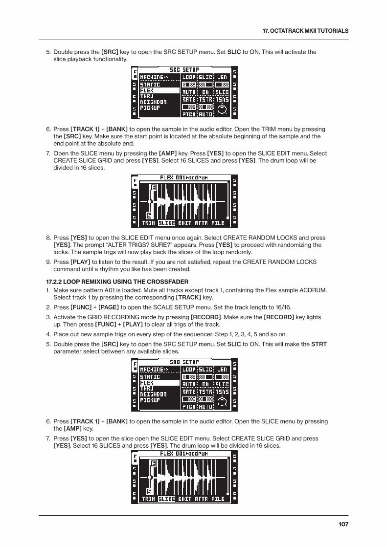
17. OCTATRACK MKII TUTORIALS
107
5. Double press the [SRC] key to open the SRC SETUP menu. Set SLIC to ON. This will activate the slice playback functionality.
6. Press [TRACK 1] + [BANK] to open the sample in the audio editor. Open the TRIM menu by pressing the [SRC] key. Make sure the start point is located at the absolute beginning of the sample and the end point at the absolute end.
7. Open the SLICE menu by pressing the [AMP] key. Press [YES] to open the SLICE EDIT menu. Select CREATE SLICE GRID and press [YES]. Select 16 SLICES and press [YES]. The drum loop will be divided in 16 slices.
8. Press [YES] to open the SLICE EDIT menu once again. Select CREATE RANDOM LOCKS and press [YES]. The prompt “ALTER TRIGS? SURE?” appears. Press [YES] to proceed with randomizing the locks. The sample trigs will now play back the slices of the loop randomly.
9. Press [PLAY] to listen to the result. If you are not satisfied, repeat the CREATE RANDOM LOCKS command until a rhythm you like has been created.
17.2.2 LOOP REMIXING USING THE CROSSFADER1. Make sure pattern A01 is loaded. Mute all tracks except track 1, containing the Flex sample ACDRUM.
Select track 1 by pressing the corresponding [TRACK] key.
2. Press [FUNC] + [PAGE] to open the SCALE SETUP menu. Set the track length to 16/16.
3. Activate the GRID RECORDING mode by pressing [RECORD]. Make sure the [RECORD] key lights up. Then press [FUNC] + [PLAY] to clear all trigs of the track.
4. Place out new sample trigs on every step of the sequencer. Step 1, 2, 3, 4, 5 and so on.
5. Double press the [SRC] key to open the SRC SETUP menu. Set SLIC to ON. This will make the STRT parameter select between any available slices.
6. Press [TRACK 1] + [BANK] to open the sample in the audio editor. Open the SLICE menu by pressing the [AMP] key.
7. Press [YES] to open the slice open the SLICE EDIT menu. Select CREATE SLICE GRID and press [YES]. Select 16 SLICES and press [YES]. The drum loop will be divided in 16 slices.
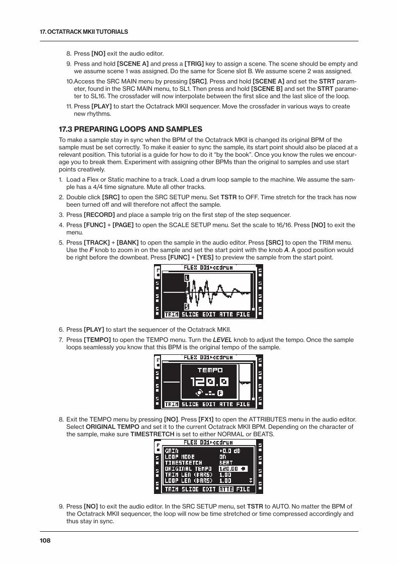
17. OCTATRACK MKII TUTORIALS
108
8. Press [NO] exit the audio editor.
9. Press and hold [SCENE A] and press a [TRIG] key to assign a scene. The scene should be empty and we assume scene 1 was assigned. Do the same for Scene slot B. We assume scene 2 was assigned.
10. Access the SRC MAIN menu by pressing [SRC]. Press and hold [SCENE A] and set the STRT param-eter, found in the SRC MAIN menu, to SL1. Then press and hold [SCENE B] and set the STRT parame-ter to SL16. The crossfader will now interpolate between the first slice and the last slice of the loop.
11. Press [PLAY] to start the Octatrack MKII sequencer. Move the crossfader in various ways to create new rhythms.
17.3 PREPARING LOOPS AND SAMPLESTo make a sample stay in sync when the BPM of the Octatrack MKII is changed its original BPM of the sample must be set correctly. To make it easier to sync the sample, its start point should also be placed at a relevant position. This tutorial is a guide for how to do it “by the book”. Once you know the rules we encour-age you to break them. Experiment with assigning other BPMs than the original to samples and use start points creatively.
1. Load a Flex or Static machine to a track. Load a drum loop sample to the machine. We assume the sam-ple has a 4/4 time signature. Mute all other tracks.
2. Double click [SRC] to open the SRC SETUP menu. Set TSTR to OFF. Time stretch for the track has now been turned off and will therefore not affect the sample.
3. Press [RECORD] and place a sample trig on the first step of the step sequencer.
4. Press [FUNC] + [PAGE] to open the SCALE SETUP menu. Set the scale to 16/16. Press [NO] to exit the menu.
5. Press [TRACK] + [BANK] to open the sample in the audio editor. Press [SRC] to open the TRIM menu. Use the F knob to zoom in on the sample and set the start point with the knob A. A good position would be right before the downbeat. Press [FUNC] + [YES] to preview the sample from the start point.
6. Press [PLAY] to start the sequencer of the Octatrack MKII.
7. Press [TEMPO] to open the TEMPO menu. Turn the LEVEL knob to adjust the tempo. Once the sample loops seamlessly you know that this BPM is the original tempo of the sample.
8. Exit the TEMPO menu by pressing [NO]. Press [FX1] to open the ATTRIBUTES menu in the audio editor. Select ORIGINAL TEMPO and set it to the current Octatrack MKII BPM. Depending on the character of the sample, make sure TIMESTRETCH is set to either NORMAL or BEATS.
9. Press [NO] to exit the audio editor. In the SRC SETUP menu, set TSTR to AUTO. No matter the BPM of the Octatrack MKII sequencer, the loop will now be time stretched or time compressed accordingly and thus stay in sync.
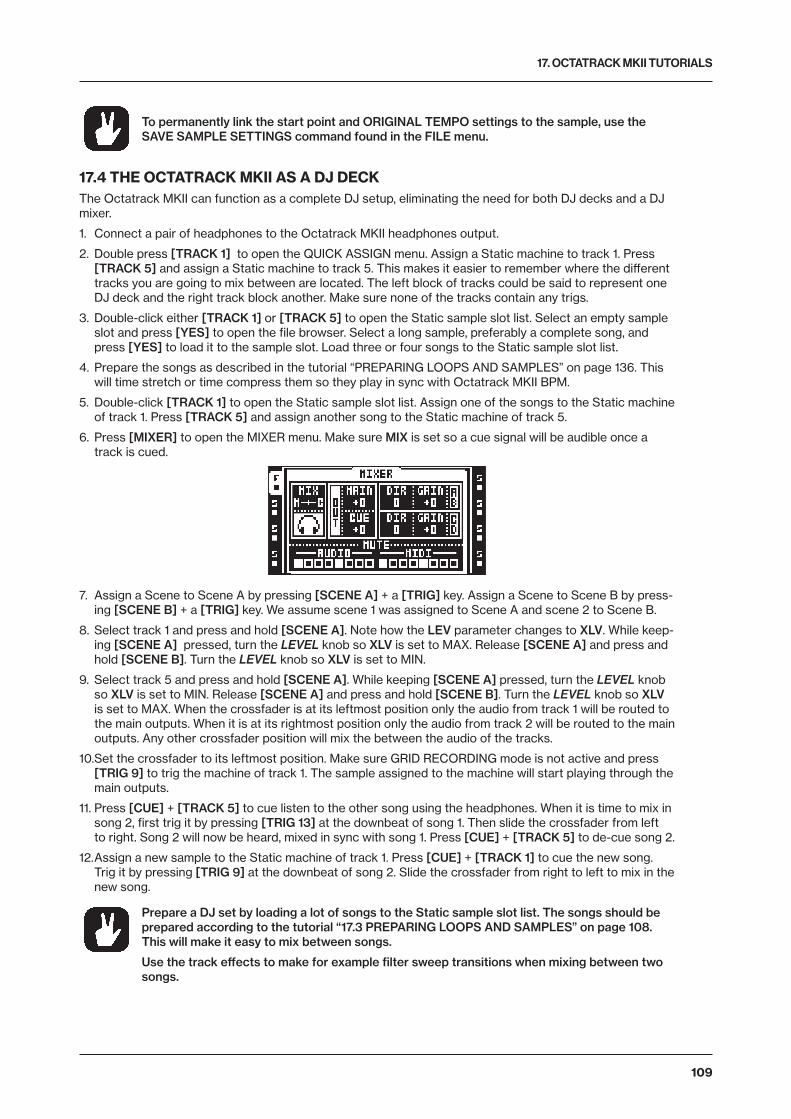
17. OCTATRACK MKII TUTORIALS
109
To permanently link the start point and ORIGINAL TEMPO settings to the sample, use the SAVE SAMPLE SETTINGS command found in the FILE menu.
17.4 THE OCTATRACK MKII AS A DJ DECKThe Octatrack MKII can function as a complete DJ setup, eliminating the need for both DJ decks and a DJ mixer.
1. Connect a pair of headphones to the Octatrack MKII headphones output.
2. Double press [TRACK 1] to open the QUICK ASSIGN menu. Assign a Static machine to track 1. Press [TRACK 5] and assign a Static machine to track 5. This makes it easier to remember where the different tracks you are going to mix between are located. The left block of tracks could be said to represent one DJ deck and the right track block another. Make sure none of the tracks contain any trigs.
3. Double-click either [TRACK 1] or [TRACK 5] to open the Static sample slot list. Select an empty sample slot and press [YES] to open the file browser. Select a long sample, preferably a complete song, and press [YES] to load it to the sample slot. Load three or four songs to the Static sample slot list.
4. Prepare the songs as described in the tutorial “PREPARING LOOPS AND SAMPLES” on page 136. This will time stretch or time compress them so they play in sync with Octatrack MKII BPM.
5. Double-click [TRACK 1] to open the Static sample slot list. Assign one of the songs to the Static machine of track 1. Press [TRACK 5] and assign another song to the Static machine of track 5.
6. Press [MIXER] to open the MIXER menu. Make sure MIX is set so a cue signal will be audible once a track is cued.
7. Assign a Scene to Scene A by pressing [SCENE A] + a [TRIG] key. Assign a Scene to Scene B by press-ing [SCENE B] + a [TRIG] key. We assume scene 1 was assigned to Scene A and scene 2 to Scene B.
8. Select track 1 and press and hold [SCENE A]. Note how the LEV parameter changes to XLV. While keep-ing [SCENE A] pressed, turn the LEVEL knob so XLV is set to MAX. Release [SCENE A] and press and hold [SCENE B]. Turn the LEVEL knob so XLV is set to MIN.
9. Select track 5 and press and hold [SCENE A]. While keeping [SCENE A] pressed, turn the LEVEL knob so XLV is set to MIN. Release [SCENE A] and press and hold [SCENE B]. Turn the LEVEL knob so XLV is set to MAX. When the crossfader is at its leftmost position only the audio from track 1 will be routed to the main outputs. When it is at its rightmost position only the audio from track 2 will be routed to the main outputs. Any other crossfader position will mix the between the audio of the tracks.
10. Set the crossfader to its leftmost position. Make sure GRID RECORDING mode is not active and press [TRIG 9] to trig the machine of track 1. The sample assigned to the machine will start playing through the main outputs.
11. Press [CUE] + [TRACK 5] to cue listen to the other song using the headphones. When it is time to mix in song 2, first trig it by pressing [TRIG 13] at the downbeat of song 1. Then slide the crossfader from left to right. Song 2 will now be heard, mixed in sync with song 1. Press [CUE] + [TRACK 5] to de-cue song 2.
12. Assign a new sample to the Static machine of track 1. Press [CUE] + [TRACK 1] to cue the new song. Trig it by pressing [TRIG 9] at the downbeat of song 2. Slide the crossfader from right to left to mix in the new song.
Prepare a DJ set by loading a lot of songs to the Static sample slot list. The songs should be prepared according to the tutorial “17.3 PREPARING LOOPS AND SAMPLES” on page 108. This will make it easy to mix between songs.
Use the track effects to make for example filter sweep transitions when mixing between two songs.
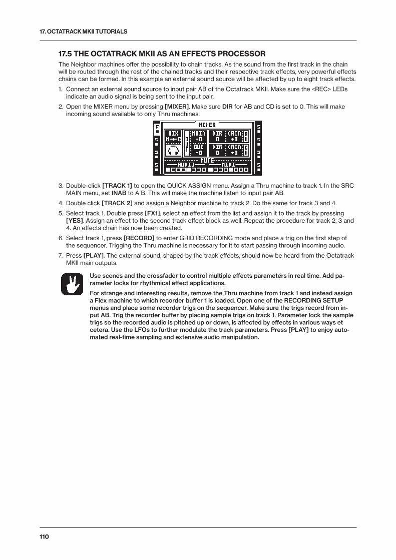
17. OCTATRACK MKII TUTORIALS
110
17.5 THE OCTATRACK MKII AS AN EFFECTS PROCESSORThe Neighbor machines offer the possibility to chain tracks. As the sound from the first track in the chain will be routed through the rest of the chained tracks and their respective track effects, very powerful effects chains can be formed. In this example an external sound source will be affected by up to eight track effects.
1. Connect an external sound source to input pair AB of the Octatrack MKII. Make sure the <REC> LEDs indicate an audio signal is being sent to the input pair.
2. Open the MIXER menu by pressing [MIXER]. Make sure DIR for AB and CD is set to 0. This will make incoming sound available to only Thru machines.
3. Double-click [TRACK 1] to open the QUICK ASSIGN menu. Assign a Thru machine to track 1. In the SRC MAIN menu, set INAB to A B. This will make the machine listen to input pair AB.
4. Double click [TRACK 2] and assign a Neighbor machine to track 2. Do the same for track 3 and 4.
5. Select track 1. Double press [FX1], select an effect from the list and assign it to the track by pressing [YES]. Assign an effect to the second track effect block as well. Repeat the procedure for track 2, 3 and 4. An effects chain has now been created.
6. Select track 1, press [RECORD] to enter GRID RECORDING mode and place a trig on the first step of the sequencer. Trigging the Thru machine is necessary for it to start passing through incoming audio.
7. Press [PLAY]. The external sound, shaped by the track effects, should now be heard from the Octatrack MKII main outputs.
Use scenes and the crossfader to control multiple effects parameters in real time. Add pa-rameter locks for rhythmical effect applications.
For strange and interesting results, remove the Thru machine from track 1 and instead assign a Flex machine to which recorder buffer 1 is loaded. Open one of the RECORDING SETUP menus and place some recorder trigs on the sequencer. Make sure the trigs record from in-put AB. Trig the recorder buffer by placing sample trigs on track 1. Parameter lock the sample trigs so the recorded audio is pitched up or down, is affected by effects in various ways et cetera. Use the LFOs to further modulate the track parameters. Press [PLAY] to enjoy auto-mated real-time sampling and extensive audio manipulation.
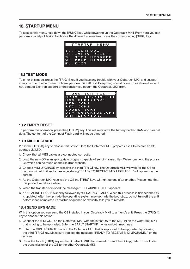
18. STARTUP MENU
111
18. STARTUP MENUTo access this menu, hold down the [FUNC] key while powering up the Octatrack MKII. From here you can perform a variety of tasks. To choose the different alternatives, press the corresponding [TRIG] key.
18.1 TEST MODETo enter this mode, press the [TRIG 1] key. If you have any trouble with your Octatrack MKII and suspect it may be due to a hardware problem, perform this self test. Everything should come up as shown below. If not, contact Elektron support or the retailer you bought the Octatrack MKII from.
18.2 EMPTY RESETTo perform this operation, press the [TRIG 2] key. This will reinitialize the battery backed RAM and clear all data. The content of the Compact Flash card will not be affected.
18.3 MIDI UPGRADEPress the [TRIG 3] key to choose this option. Here the Octatrack MKII prepares itself to receive an OS upgrade via MIDI.
1. Check that all MIDI cables are connected correctly.
2. Load the new OS in an appropriate program capable of sending sysex files. We recommend the program C6 which can be found on the Elektron website.
3. Choose MIDI UPGRADE by pressing the third [TRIG] key. The Octatrack MKII will wait for the OS to be transmitted to it and a message stating “READY TO RECEIVE MIDI UPGRADE…” will appear on the screen.
4. As the Octatrack MKII receives the OS the [TRIG] keys will light up one after another. Please note that this procedure takes a while.
5. When the transfer is finished the message “PREPARING FLASH” appears.
6. “PREPARING FLASH” is shortly followed by “UPDATING FLASH”. When this process is finished the OS is updated. After the upgrade the operating system may upgrade the bootstrap, do not turn off the unit before it has completed its startup sequence or explicitly tells you to restart!
18.4 SEND UPGRADEWith this option you can send the OS installed in your Octatrack MKII to a friend’s unit. Press the [TRIG 4] key to choose this option.
1. Connect the MIDI OUT on the Octatrack MKII with the latest OS to the MIDI IN on the Octatrack MKII that is going to be upgraded. Enter the EARLY STARTUP menus on both machines.
2. Enter the MIDI UPGRADE mode in the Octatrack MKII that is supposed to be upgraded by pressing the third [TRIG] key. Make sure you see the message “READY TO RECEIVE MIDI UPGRADE…” on the screen.
3. Press the fourth [TRIG] key on the Octatrack MKII that is used to send the OS upgrade. This will start the transmission of the OS to the other Octatrack MKII.

18. STARTUP MENU
112
18.5 EXITPress the [TRIG 5] key to exit the STARTUP menu.
For faster OS updates, utilize the speed of the Elektron TurboCharge protocol. You will need to have the MIDI IN port of the receiving machine connected to the MIDI OUT port of the transmitting machine and vice versa for this to function.
The most convenient way of upgrading the OS is by updating from the Compact Flash card. This is performed in the OS UPDATE menu. Read more about this menu in the section “8.5 SYSTEM” on page 32.
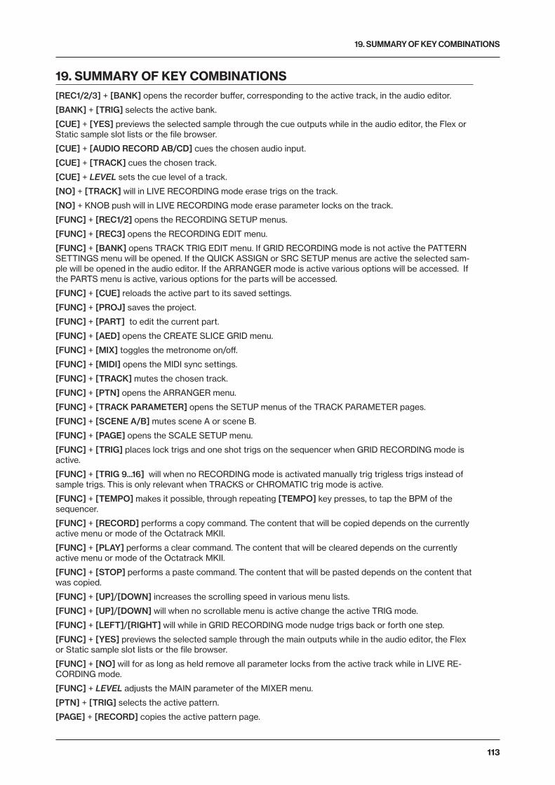
19. SUMMARY OF KEY COMBINATIONS
113
19. SUMMARY OF KEY COMBINATIONS[REC1/2/3] + [BANK] opens the recorder buffer, corresponding to the active track, in the audio editor.
[BANK] + [TRIG] selects the active bank.
[CUE] + [YES] previews the selected sample through the cue outputs while in the audio editor, the Flex or Static sample slot lists or the file browser.
[CUE] + [AUDIO RECORD AB/CD] cues the chosen audio input.
[CUE] + [TRACK] cues the chosen track.
[CUE] + LEVEL sets the cue level of a track.
[NO] + [TRACK] will in LIVE RECORDING mode erase trigs on the track.
[NO] + KNOB push will in LIVE RECORDING mode erase parameter locks on the track.
[FUNC] + [REC1/2] opens the RECORDING SETUP menus.
[FUNC] + [REC3] opens the RECORDING EDIT menu.
[FUNC] + [BANK] opens TRACK TRIG EDIT menu. If GRID RECORDING mode is not active the PATTERN SETTINGS menu will be opened. If the QUICK ASSIGN or SRC SETUP menus are active the selected sam-ple will be opened in the audio editor. If the ARRANGER mode is active various options will be accessed. If the PARTS menu is active, various options for the parts will be accessed.
[FUNC] + [CUE] reloads the active part to its saved settings.
[FUNC] + [PROJ] saves the project.
[FUNC] + [PART] to edit the current part.
[FUNC] + [AED] opens the CREATE SLICE GRID menu.
[FUNC] + [MIX] toggles the metronome on/off.
[FUNC] + [MIDI] opens the MIDI sync settings.
[FUNC] + [TRACK] mutes the chosen track.
[FUNC] + [PTN] opens the ARRANGER menu.
[FUNC] + [TRACK PARAMETER] opens the SETUP menus of the TRACK PARAMETER pages.
[FUNC] + [SCENE A/B] mutes scene A or scene B.
[FUNC] + [PAGE] opens the SCALE SETUP menu.
[FUNC] + [TRIG] places lock trigs and one shot trigs on the sequencer when GRID RECORDING mode is active.
[FUNC] + [TRIG 9...16] will when no RECORDING mode is activated manually trig trigless trigs instead of sample trigs. This is only relevant when TRACKS or CHROMATIC trig mode is active.
[FUNC] + [TEMPO] makes it possible, through repeating [TEMPO] key presses, to tap the BPM of the sequencer.
[FUNC] + [RECORD] performs a copy command. The content that will be copied depends on the currently active menu or mode of the Octatrack MKII.
[FUNC] + [PLAY] performs a clear command. The content that will be cleared depends on the currently active menu or mode of the Octatrack MKII.
[FUNC] + [STOP] performs a paste command. The content that will be pasted depends on the content that was copied.
[FUNC] + [UP]/[DOWN] increases the scrolling speed in various menu lists.
[FUNC] + [UP]/[DOWN] will when no scrollable menu is active change the active TRIG mode.
[FUNC] + [LEFT]/[RIGHT] will while in GRID RECORDING mode nudge trigs back or forth one step.
[FUNC] + [YES] previews the selected sample through the main outputs while in the audio editor, the Flex or Static sample slot lists or the file browser.
[FUNC] + [NO] will for as long as held remove all parameter locks from the active track while in LIVE RE-CORDING mode.
[FUNC] + LEVEL adjusts the MAIN parameter of the MIXER menu.
[PTN] + [TRIG] selects the active pattern.
[PAGE] + [RECORD] copies the active pattern page.
19. SUMMARY OF KEY COMBINATIONS
114
[PAGE] + [PLAY] clears the active pattern page.
[PAGE] + [STOP] pastes a copied pattern page to the active pattern page.
[SCENE A/B] + [TRIG] assigns a scene to the selected scene slot.
[TRACK] + [PLAY] trigs the sample assigned to the machine of the track.
[TRACK] + [STOP] stops playback of the sample assigned to the machine of the track.
[TRACK] + [BANK] opens the sample assigned to the track in the audio editor.
[TRACK] + [REC1/2] initiates sampling from the audio inputs.
[TRACK] + [REC3] initiates internal sampling of the audio tracks.
[TRACK] + [YES] re-arms any one shot recorder trigs of the track whose [TRACK] key was pressed.
[TRACK] + [NO] disarms any one shot recorder trigs of the track whose [TRACK] key was pressed.
[TRACK] + [LEFT]/[RIGHT] nudges the BPM of the sample of the track.
[TRACK PARAMETER] + [RECORD] copies the parameter settings of a TRACK PARAMETER page.
[TRACK PARAMETER] + [STOP] pastes the copied parameter settings of a TRACK PARAMETER page.
[TRACK PARAMETER] + [PLAY] initializes the settings of a TRACK PARAMETER page.
[SCENE] + [RECORD] copies the assigned scene.
[SCENE] + [PLAY] clears the assigned scene.
[SCENE] + [STOP] pastes a copied scene to the scene assigned to the scene slot.
[TRIG] + [YES] will turn a lock trig into a trigless trig.
[TRIG]+ [NO] will turn a sample trig to a trigless trig. A trigless trig will be turned to a lock trig.
[TRIG] + [UP]/[DOWN] will, while in GRID RECORDING mode, open the SAMPLE LOCK menu.
[TRIG] + [LEFT]/[RIGHT] will while in GRID RECORDING mode open the MICRO TIMING menu.
[TRIG] + [RECORD] copies the selected trig.
[TRIG] + [PLAY] clears all parameter locks from the selected trig.
[TRIG] + [STOP] pastes a previously copied trig.
20. TECHNICAL INFORMATION
115
20. TECHNICAL INFORMATION
ELECTRICAL SPECIFICATIONSImpedance balanced audio outputs Main outputs level: +17 dBu peak Output impedance: 440 Ω unbalanced Digital S/N ratio: 104 dB (20–20,000 Hz)
Headphones output Headphones out level: +17 dBu peak Output impedance: 55 Ω
Balanced audio inputs Input level: +17 dBu peak Audio input impedance: 21 kΩ Digital S/N ratio: 106 dB (20–20,000 Hz)
Unit power consumption: 7 W typical Compatible Elektron power supply: PSU-3b
HARDWARE128 × 64 pixel OLED screen MIDI In/Out/Thru 2 × 1/4” impedance balanced main audio out jacks 2 × 1/4” impedance balanced cue audio out jacks 4 × 1/4” balanced/unbalanced external input jacks 1 × 1/4” stereo headphone jack 44,1 kHz, 24-bit D/A and A/D converters Hi-speed USB 2.0 port Power inlet: Center positive 5.5 × 2.5 mm barrel jack, 12 V DC, 2 A
PHYSICAL SPECIFICATIONSSturdy steel casing Dimensions: W 340 × D 184 × H 63 mm (13.3” × 7.2” × 2.5”) (including knobs, jacks, and rubber feet) Weight: approximately 2.3 kg (5 lbs) Maximum recommended ambient operating temperature: +40˚C (+104˚F)
21. CREDITS AND CONTACT INFORMATION
CREDITS
PRODUCT DESIGN AND DEVELOPMENTOscar Albinsson Ali Alper Çakır Magnus Forsell Anders Gärder Jimmy Myhrman Jon Mårtensson David Revelj Mattias Rickardsson Daniel Troberg
ADDITIONAL DESIGNJohan Damerau Ufuk Demir Thomas Ekelund Simon Mattisson Olle Petersson Cenk Sayınlı
DOCUMENTATION Erik Ångman
CONTACT INFORMATION
ELEKTRON WEBSITEhttps://www.elektron.se
OFFICE ADDRESSElektron Music Machines MAV AB Sockerbruket 9 SE-414 51 Gothenburg Sweden
TELEPHONE+46 (0)31 743 744 0
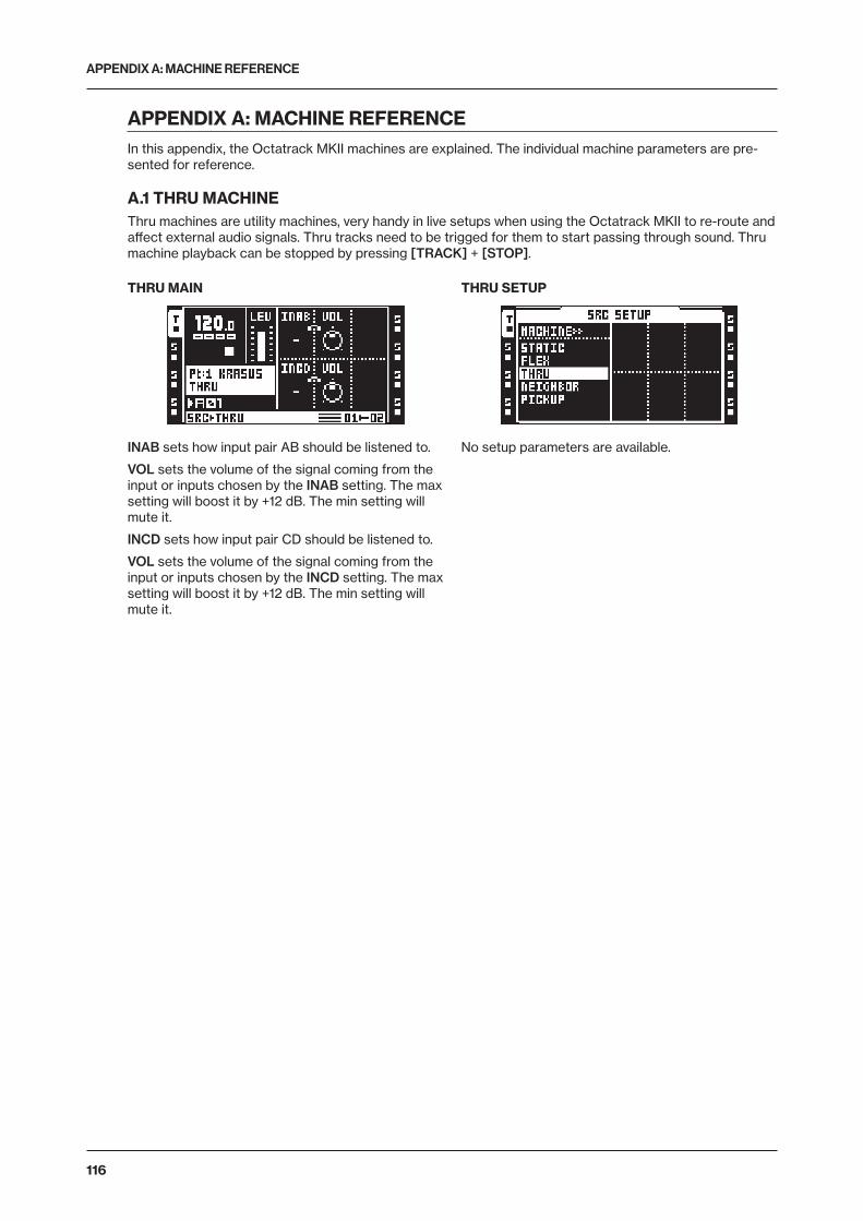
APPENDIX A: MACHINE REFERENCE
116
APPENDIX A: MACHINE REFERENCEIn this appendix, the Octatrack MKII machines are explained. The individual machine parameters are pre-sented for reference.
A.1 THRU MACHINEThru machines are utility machines, very handy in live setups when using the Octatrack MKII to re-route and affect external audio signals. Thru tracks need to be trigged for them to start passing through sound. Thru machine playback can be stopped by pressing [TRACK] + [STOP].
THRU MAIN
INAB sets how input pair AB should be listened to.
VOL sets the volume of the signal coming from the input or inputs chosen by the INAB setting. The max setting will boost it by +12 dB. The min setting will mute it.
INCD sets how input pair CD should be listened to.
VOL sets the volume of the signal coming from the input or inputs chosen by the INCD setting. The max setting will boost it by +12 dB. The min setting will mute it.
THRU SETUP
No setup parameters are available.
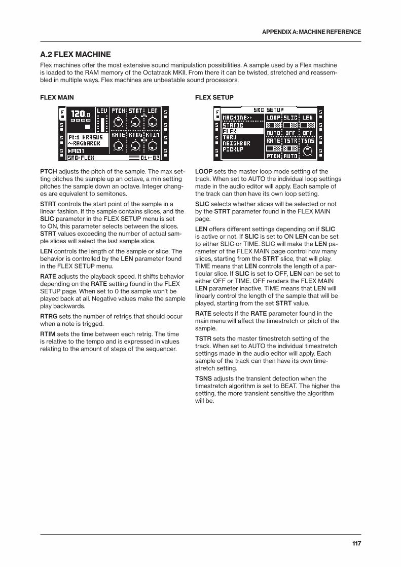
APPENDIX A: MACHINE REFERENCE
117
A.2 FLEX MACHINEFlex machines offer the most extensive sound manipulation possibilities. A sample used by a Flex machine is loaded to the RAM memory of the Octatrack MKII. From there it can be twisted, stretched and reassem-bled in multiple ways. Flex machines are unbeatable sound processors.
FLEX MAIN
PTCH adjusts the pitch of the sample. The max set-ting pitches the sample up an octave, a min setting pitches the sample down an octave. Integer chang-es are equivalent to semitones.
STRT controls the start point of the sample in a linear fashion. If the sample contains slices, and the SLIC parameter in the FLEX SETUP menu is set to ON, this parameter selects between the slices. STRT values exceeding the number of actual sam-ple slices will select the last sample slice.
LEN controls the length of the sample or slice. The behavior is controlled by the LEN parameter found in the FLEX SETUP menu.
RATE adjusts the playback speed. It shifts behavior depending on the RATE setting found in the FLEX SETUP page. When set to 0 the sample won’t be played back at all. Negative values make the sample play backwards.
RTRG sets the number of retrigs that should occur when a note is trigged.
RTIM sets the time between each retrig. The time is relative to the tempo and is expressed in values relating to the amount of steps of the sequencer.
FLEX SETUP
LOOP sets the master loop mode setting of the track. When set to AUTO the individual loop settings made in the audio editor will apply. Each sample of the track can then have its own loop setting.
SLIC selects whether slices will be selected or not by the STRT parameter found in the FLEX MAIN page.
LEN offers different settings depending on if SLIC is active or not. If SLIC is set to ON LEN can be set to either SLIC or TIME. SLIC will make the LEN pa-rameter of the FLEX MAIN page control how many slices, starting from the STRT slice, that will play. TIME means that LEN controls the length of a par-ticular slice. If SLIC is set to OFF, LEN can be set to either OFF or TIME. OFF renders the FLEX MAIN LEN parameter inactive. TIME means that LEN will linearly control the length of the sample that will be played, starting from the set STRT value.
RATE selects if the RATE parameter found in the main menu will affect the timestretch or pitch of the sample.
TSTR sets the master timestretch setting of the track. When set to AUTO the individual timestretch settings made in the audio editor will apply. Each sample of the track can then have its own time-stretch setting.
TSNS adjusts the transient detection when the timestretch algorithm is set to BEAT. The higher the setting, the more transient sensitive the algorithm will be.
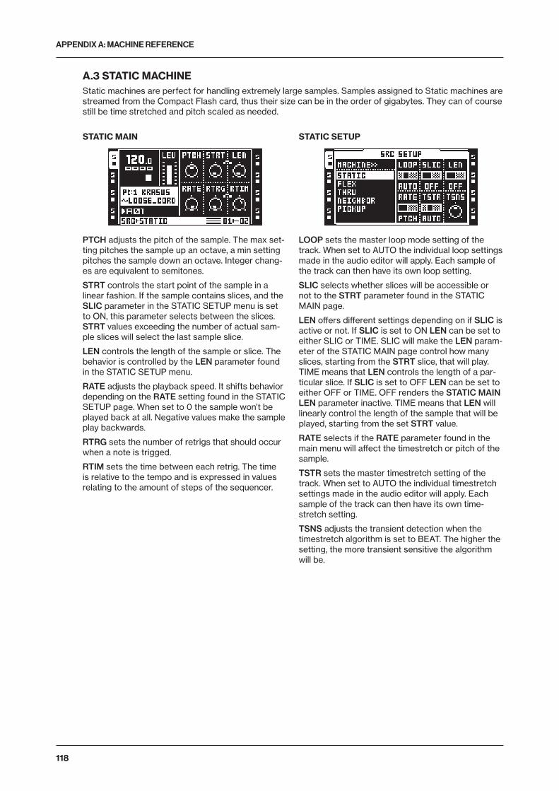
APPENDIX A: MACHINE REFERENCE
118
A.3 STATIC MACHINEStatic machines are perfect for handling extremely large samples. Samples assigned to Static machines are streamed from the Compact Flash card, thus their size can be in the order of gigabytes. They can of course still be time stretched and pitch scaled as needed.
STATIC MAIN
PTCH adjusts the pitch of the sample. The max set-ting pitches the sample up an octave, a min setting pitches the sample down an octave. Integer chang-es are equivalent to semitones.
STRT controls the start point of the sample in a linear fashion. If the sample contains slices, and the SLIC parameter in the STATIC SETUP menu is set to ON, this parameter selects between the slices. STRT values exceeding the number of actual sam-ple slices will select the last sample slice.
LEN controls the length of the sample or slice. The behavior is controlled by the LEN parameter found in the STATIC SETUP menu.
RATE adjusts the playback speed. It shifts behavior depending on the RATE setting found in the STATIC SETUP page. When set to 0 the sample won’t be played back at all. Negative values make the sample play backwards.
RTRG sets the number of retrigs that should occur when a note is trigged.
RTIM sets the time between each retrig. The time is relative to the tempo and is expressed in values relating to the amount of steps of the sequencer.
STATIC SETUP
LOOP sets the master loop mode setting of the track. When set to AUTO the individual loop settings made in the audio editor will apply. Each sample of the track can then have its own loop setting.
SLIC selects whether slices will be accessible or not to the STRT parameter found in the STATIC MAIN page.
LEN offers different settings depending on if SLIC is active or not. If SLIC is set to ON LEN can be set to either SLIC or TIME. SLIC will make the LEN param-eter of the STATIC MAIN page control how many slices, starting from the STRT slice, that will play. TIME means that LEN controls the length of a par-ticular slice. If SLIC is set to OFF LEN can be set to either OFF or TIME. OFF renders the STATIC MAIN LEN parameter inactive. TIME means that LEN will linearly control the length of the sample that will be played, starting from the set STRT value.
RATE selects if the RATE parameter found in the main menu will affect the timestretch or pitch of the sample.
TSTR sets the master timestretch setting of the track. When set to AUTO the individual timestretch settings made in the audio editor will apply. Each sample of the track can then have its own time-stretch setting.
TSNS adjusts the transient detection when the timestretch algorithm is set to BEAT. The higher the setting, the more transient sensitive the algorithm will be.
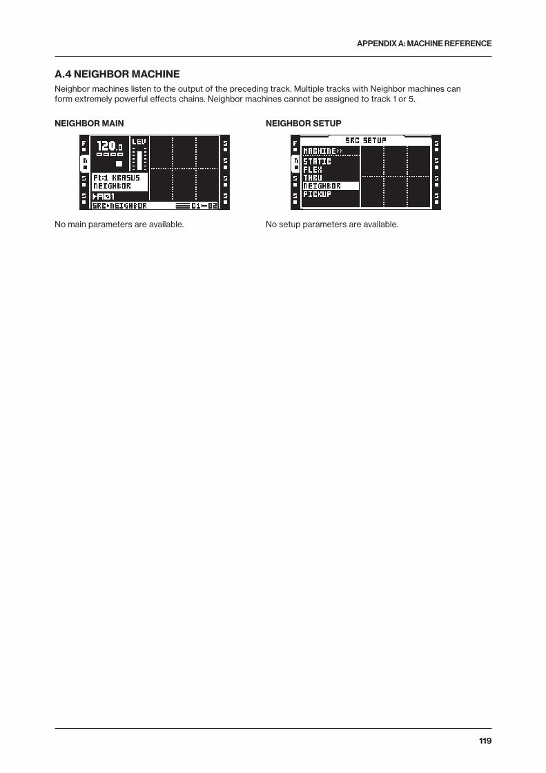
APPENDIX A: MACHINE REFERENCE
119
A.4 NEIGHBOR MACHINENeighbor machines listen to the output of the preceding track. Multiple tracks with Neighbor machines can form extremely powerful effects chains. Neighbor machines cannot be assigned to track 1 or 5.
NEIGHBOR MAIN
No main parameters are available.
NEIGHBOR SETUP
No setup parameters are available.
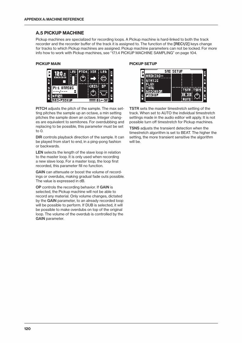
APPENDIX A: MACHINE REFERENCE
120
A.5 PICKUP MACHINEPickup machines are specialized for recording loops. A Pickup machine is hard-linked to both the track recorder and the recorder buffer of the track it is assigned to. The function of the [REC1/2] keys change for tracks to which Pickup machines are assigned. Pickup machine parameters can not be locked. For more info how to work with Pickup machines, see “17.1.4 PICKUP MACHINE SAMPLING” on page 104.
PICKUP MAIN
PITCH adjusts the pitch of the sample. The max set-ting pitches the sample up an octave, a min setting pitches the sample down an octave. Integer chang-es are equivalent to semitones. For overdubbing and replacing to be possible, this parameter must be set to 0.
DIR controls playback direction of the sample. It can be played from start to end, in a ping-pong fashion or backwards.
LEN selects the length of the slave loop in relation to the master loop. It is only used when recording a new slave loop. For a master loop, the loop first recorded, this parameter fill no function.
GAIN can attenuate or boost the volume of record-ings or overdubs, making gradual fade outs possible. The value is expressed in dB.
OP controls the recording behavior. If GAIN is selected, the Pickup machine will not be able to record any material. Only volume changes, dictated by the GAIN parameter, to an already recorded loop will be possible to perform. If DUB is selected, it will be possible to make overdubs on top of the original loop. The volume of the overdub is controlled by the GAIN parameter.
PICKUP SETUP
TSTR sets the master timestretch setting of the track. When set to AUTO the individual timestretch settings made in the audio editor will apply. It is not possible turn off timestretch for Pickup machines.
TSNS adjusts the transient detection when the timestretch algorithm is set to BEAT. The higher the setting, the more transient sensitive the algorithm will be.
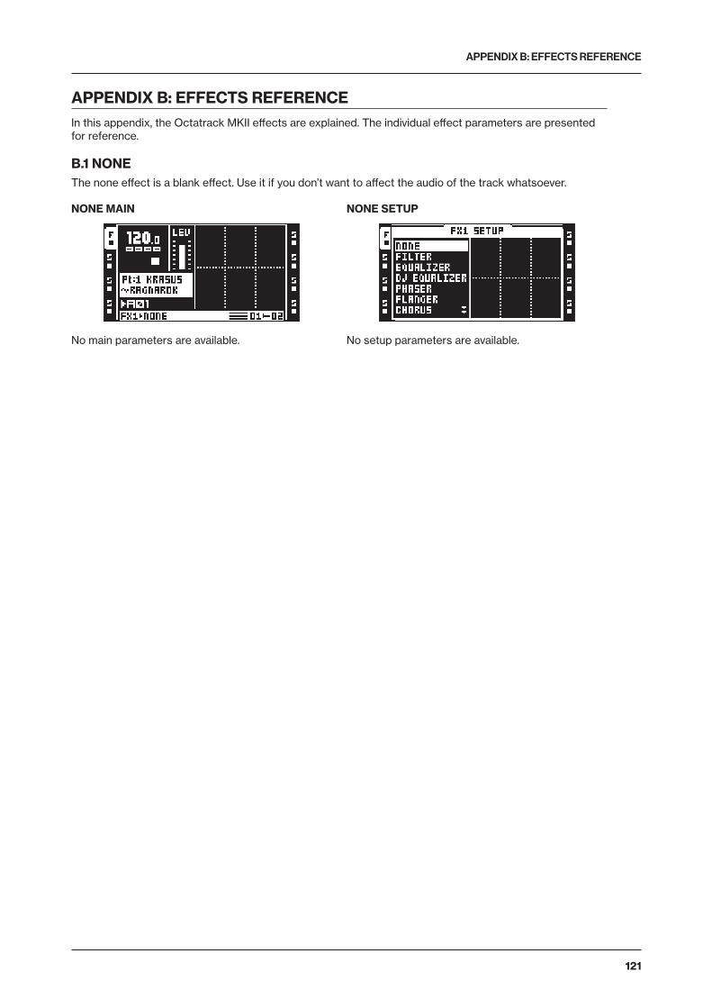
APPENDIX B: EFFECTS REFERENCE
121
APPENDIX B: EFFECTS REFERENCEIn this appendix, the Octatrack MKII effects are explained. The individual effect parameters are presented for reference.
B.1 NONEThe none effect is a blank effect. Use it if you don’t want to affect the audio of the track whatsoever.
NONE MAIN
No main parameters are available.
NONE SETUP
No setup parameters are available.
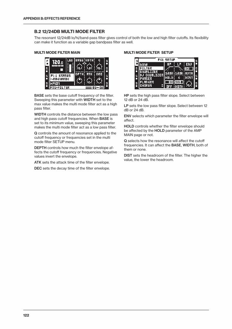
APPENDIX B: EFFECTS REFERENCE
122
B.2 12/24DB MULTI MODE FILTERThe resonant 12/24dB lo/hi/band-pass filter gives control of both the low and high filter cutoffs. Its flexibility can make it function as a variable gap bandpass filter as well.
MULTI MODE FILTER MAIN
BASE sets the base cutoff frequency of the filter. Sweeping this parameter with WIDTH set to the max value makes the multi mode filter act as a high pass filter.
WIDTH controls the distance between the low pass and high pass cutoff frequencies. When BASE is set to its minimum value, sweeping this parameter makes the multi mode filter act as a low pass filter.
Q controls the amount of resonance applied to the cutoff frequency or frequencies set in the multi mode filter SETUP menu.
DEPTH controls how much the filter envelope af-fects the cutoff frequency or frequencies. Negative values invert the envelope.
ATK sets the attack time of the filter envelope.
DEC sets the decay time of the filter envelope.
MULTI MODE FILTER SETUP
HP sets the high pass filter slope. Select between 12 dB or 24 dB.
LP sets the low pass filter slope. Select between 12 dB or 24 dB.
ENV selects which parameter the filter envelope will affect.
HOLD controls whether the filter envelope should be affected by the HOLD parameter of the AMP MAIN page or not.
Q selects how the resonance will affect the cutoff frequencies. It can affect the BASE, WIDTH, both of them or none.
DIST sets the headroom of the filter. The higher the value, the lower the headroom.
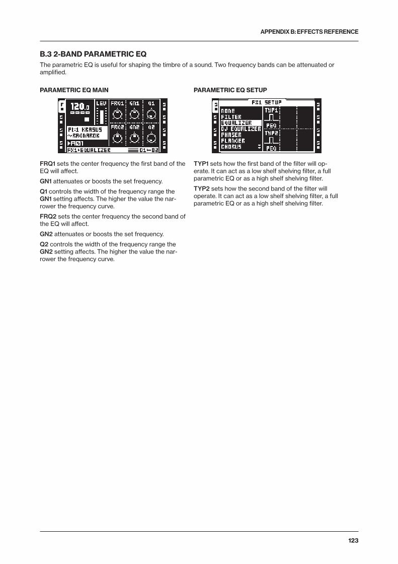
APPENDIX B: EFFECTS REFERENCE
123
B.3 2-BAND PARAMETRIC EQThe parametric EQ is useful for shaping the timbre of a sound. Two frequency bands can be attenuated or amplified.
PARAMETRIC EQ MAIN
FRQ1 sets the center frequency the first band of the EQ will affect.
GN1 attenuates or boosts the set frequency.
Q1 controls the width of the frequency range the GN1 setting affects. The higher the value the nar-rower the frequency curve.
FRQ2 sets the center frequency the second band of the EQ will affect.
GN2 attenuates or boosts the set frequency.
Q2 controls the width of the frequency range the GN2 setting affects. The higher the value the nar-rower the frequency curve.
PARAMETRIC EQ SETUP
TYP1 sets how the first band of the filter will op-erate. It can act as a low shelf shelving filter, a full parametric EQ or as a high shelf shelving filter.
TYP2 sets how the second band of the filter will operate. It can act as a low shelf shelving filter, a full parametric EQ or as a high shelf shelving filter.
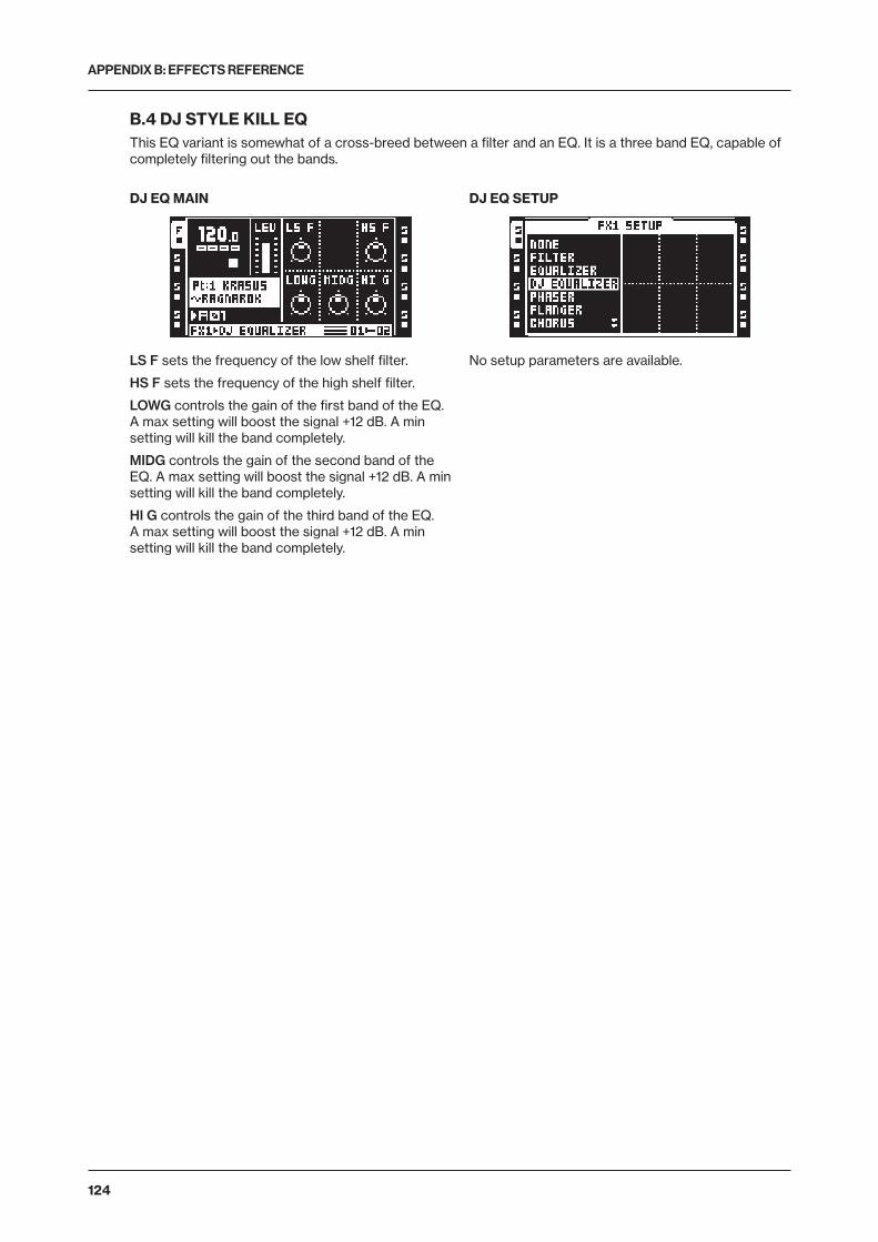
APPENDIX B: EFFECTS REFERENCE
124
B.4 DJ STYLE KILL EQThis EQ variant is somewhat of a cross-breed between a filter and an EQ. It is a three band EQ, capable of completely filtering out the bands.
DJ EQ MAIN
LS F sets the frequency of the low shelf filter.
HS F sets the frequency of the high shelf filter.
LOWG controls the gain of the first band of the EQ. A max setting will boost the signal +12 dB. A min setting will kill the band completely.
MIDG controls the gain of the second band of the EQ. A max setting will boost the signal +12 dB. A min setting will kill the band completely.
HI G controls the gain of the third band of the EQ. A max setting will boost the signal +12 dB. A min setting will kill the band completely.
DJ EQ SETUP
No setup parameters are available.
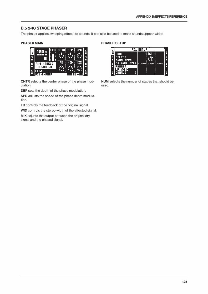
APPENDIX B: EFFECTS REFERENCE
125
B.5 2-10 STAGE PHASERThe phaser applies sweeping effects to sounds. It can also be used to make sounds appear wider.
PHASER MAIN
CNTR selects the center phase of the phase mod-ulation.
DEP sets the depth of the phase modulation.
SPD adjusts the speed of the phase depth modula-tion.
FB controls the feedback of the original signal.
WID controls the stereo width of the affected signal.
MIX adjusts the output between the original dry signal and the phased signal.
PHASER SETUP
NUM selects the number of stages that should be used.
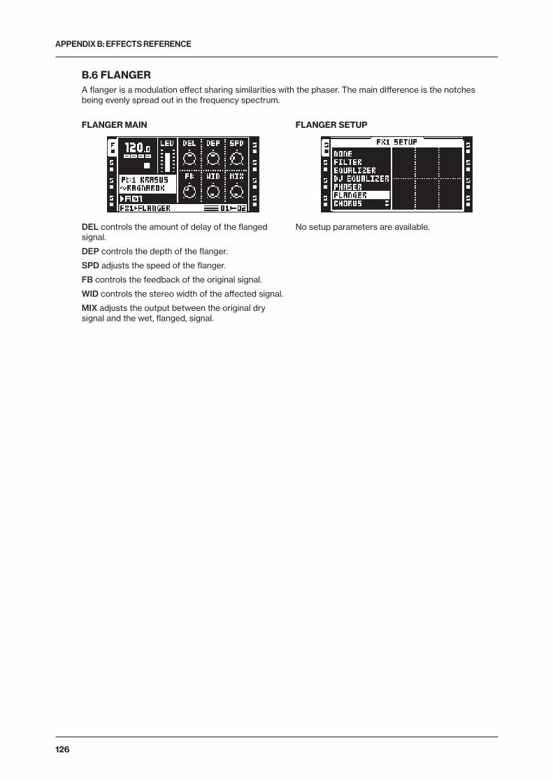
APPENDIX B: EFFECTS REFERENCE
126
B.6 FLANGERA flanger is a modulation effect sharing similarities with the phaser. The main difference is the notches being evenly spread out in the frequency spectrum.
FLANGER MAIN
DEL controls the amount of delay of the flanged signal.
DEP controls the depth of the flanger.
SPD adjusts the speed of the flanger.
FB controls the feedback of the original signal.
WID controls the stereo width of the affected signal.
MIX adjusts the output between the original dry signal and the wet, flanged, signal.
FLANGER SETUP
No setup parameters are available.
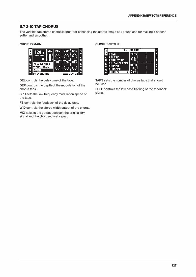
APPENDIX B: EFFECTS REFERENCE
127
B.7 2-10 TAP CHORUSThe variable tap stereo chorus is great for enhancing the stereo image of a sound and for making it appear softer and smoother.
CHORUS MAIN
DEL controls the delay time of the taps.
DEP controls the depth of the modulation of the chorus taps.
SPD sets the low frequency modulation speed of the taps.
FB controls the feedback of the delay taps.
WID controls the stereo width output of the chorus.
MIX adjusts the output between the original dry signal and the chorused wet signal.
CHORUS SETUP
TAPS sets the number of chorus taps that should be used.
FBLP controls the low pass filtering of the feedback signal.
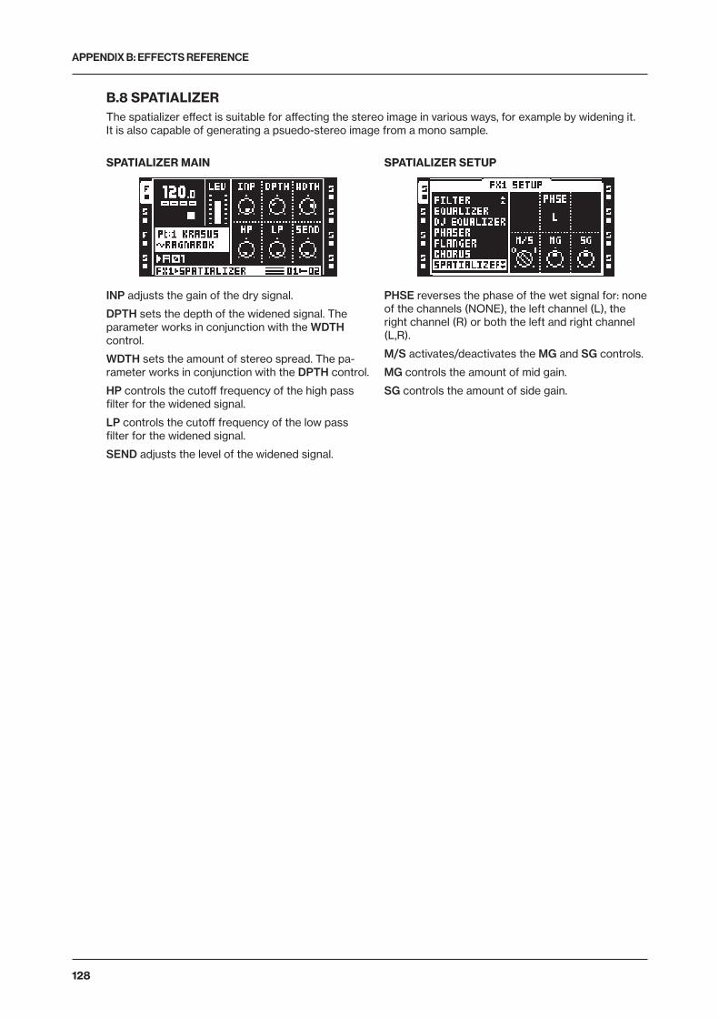
APPENDIX B: EFFECTS REFERENCE
128
B.8 SPATIALIZERThe spatializer effect is suitable for affecting the stereo image in various ways, for example by widening it. It is also capable of generating a psuedo-stereo image from a mono sample.
SPATIALIZER MAIN
INP adjusts the gain of the dry signal.
DPTH sets the depth of the widened signal. The parameter works in conjunction with the WDTH control.
WDTH sets the amount of stereo spread. The pa-rameter works in conjunction with the DPTH control.
HP controls the cutoff frequency of the high pass filter for the widened signal.
LP controls the cutoff frequency of the low pass filter for the widened signal.
SEND adjusts the level of the widened signal.
SPATIALIZER SETUP
PHSE reverses the phase of the wet signal for: none of the channels (NONE), the left channel (L), the right channel (R) or both the left and right channel (L,R).
M/S activates/deactivates the MG and SG controls.
MG controls the amount of mid gain.
SG controls the amount of side gain.
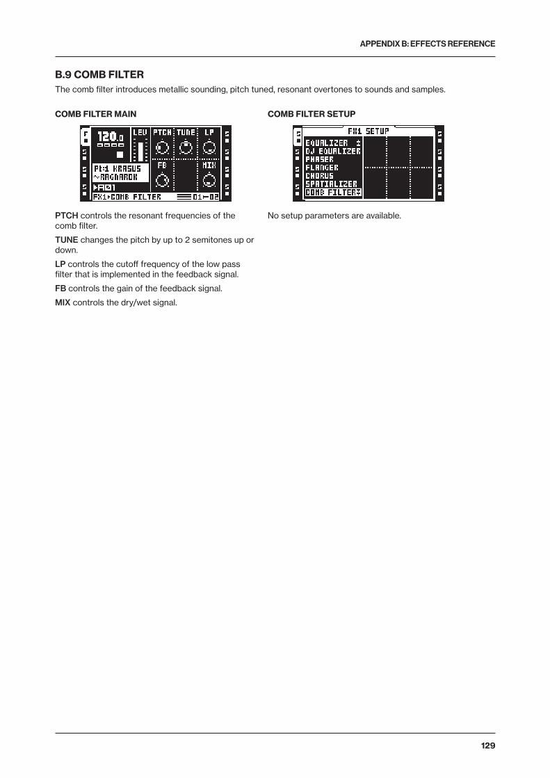
APPENDIX B: EFFECTS REFERENCE
129
B.9 COMB FILTERThe comb filter introduces metallic sounding, pitch tuned, resonant overtones to sounds and samples.
COMB FILTER MAIN
PTCH controls the resonant frequencies of the comb filter.
TUNE changes the pitch by up to 2 semitones up or down.
LP controls the cutoff frequency of the low pass filter that is implemented in the feedback signal.
FB controls the gain of the feedback signal.
MIX controls the dry/wet signal.
COMB FILTER SETUP
No setup parameters are available.
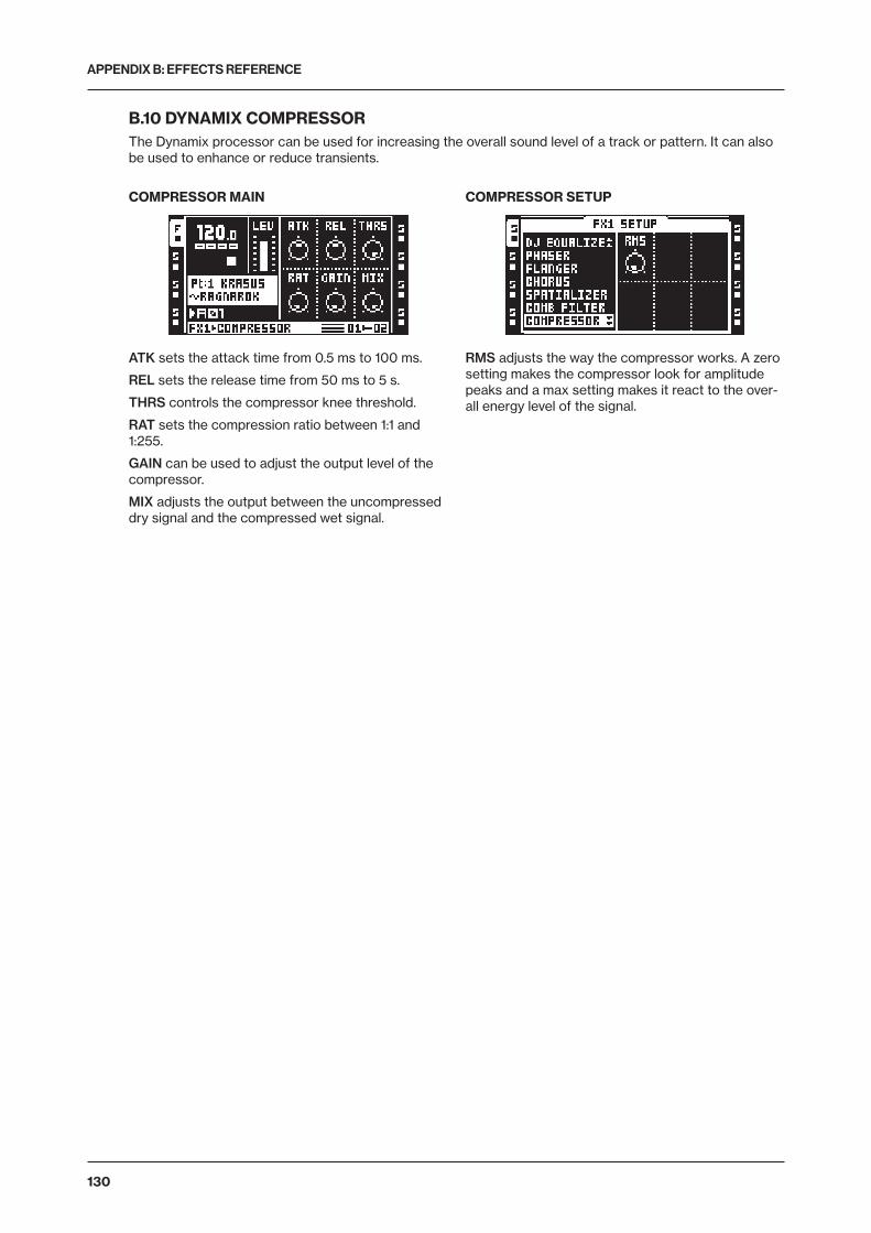
APPENDIX B: EFFECTS REFERENCE
130
B.10 DYNAMIX COMPRESSORThe Dynamix processor can be used for increasing the overall sound level of a track or pattern. It can also be used to enhance or reduce transients.
COMPRESSOR MAIN
ATK sets the attack time from 0.5 ms to 100 ms.
REL sets the release time from 50 ms to 5 s.
THRS controls the compressor knee threshold.
RAT sets the compression ratio between 1:1 and 1:255.
GAIN can be used to adjust the output level of the compressor.
MIX adjusts the output between the uncompressed dry signal and the compressed wet signal.
COMPRESSOR SETUP
RMS adjusts the way the compressor works. A zero setting makes the compressor look for amplitude peaks and a max setting makes it react to the over-all energy level of the signal.
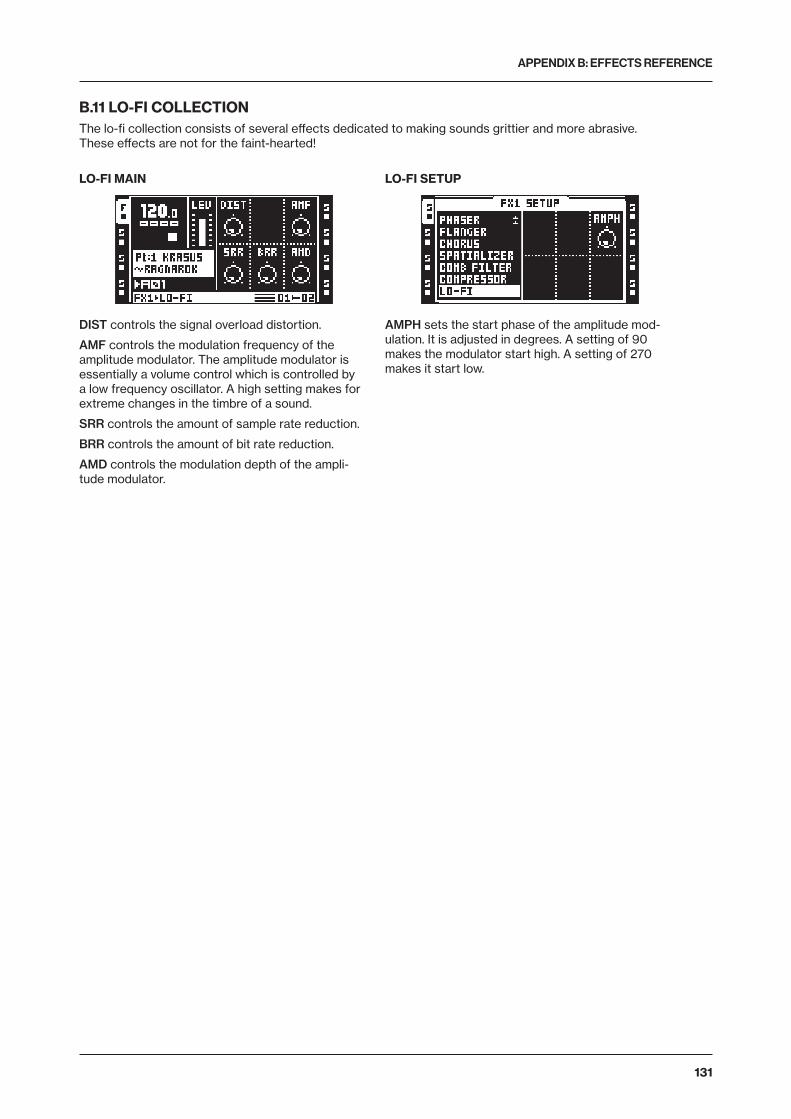
APPENDIX B: EFFECTS REFERENCE
131
B.11 LO-FI COLLECTIONThe lo-fi collection consists of several effects dedicated to making sounds grittier and more abrasive. These effects are not for the faint-hearted!
LO-FI MAIN
DIST controls the signal overload distortion.
AMF controls the modulation frequency of the amplitude modulator. The amplitude modulator is essentially a volume control which is controlled by a low frequency oscillator. A high setting makes for extreme changes in the timbre of a sound.
SRR controls the amount of sample rate reduction.
BRR controls the amount of bit rate reduction.
AMD controls the modulation depth of the ampli-tude modulator.
LO-FI SETUP
AMPH sets the start phase of the amplitude mod-ulation. It is adjusted in degrees. A setting of 90 makes the modulator start high. A setting of 270 makes it start low.
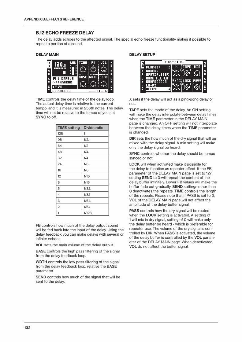
APPENDIX B: EFFECTS REFERENCE
132
B.12 ECHO FREEZE DELAYThe delay adds echoes to the affected signal. The special echo freeze functionality makes it possible to repeat a portion of a sound.
DELAY MAIN
TIME controls the delay time of the delay loop. The actual delay time is relative to the current tempo, and it is measured in 256th notes. The delay time will not be relative to the tempo of you set SYNC to off.
TIME setting Divide ratio
128 1
96 1/2.
64 1/2
48 1/4.
32 1/4
24 1/8.
16 1/8
12 1/16.
8 1/16
6 1/32.
4 1/32
3 1/64.
2 1/64
1 1/128
FB controls how much of the delay output sound will be fed back into the input of the delay. Using the delay feedback you can make delays with several or infinite echoes.
VOL sets the main volume of the delay output.
BASE controls the high pass filtering of the signal from the delay feedback loop.
WDTH controls the low pass filtering of the signal from the delay feedback loop, relative the BASE parameter.
SEND controls how much of the signal that will be sent to the delay.
DELAY SETUP
X sets if the delay will act as a ping-pong delay or not.
TAPE sets the mode of the delay. An ON setting will make the delay interpolate between delay times when the TIME parameter in the DELAY MAIN page is changed. An OFF setting will not interpolate between the delay times when the TIME parameter is changed.
DIR sets the how much of the dry signal that will be mixed with the delay signal. A min setting will make only the delay signal be heard.
SYNC controls whether the delay should be tempo synced or not.
LOCK will when activated make it possible for the delay to function as repeater effect. If the FB parameter of the DELAY MAIN page is set to 127, setting SEND to 0 will repeat the content of the delay buffer infinitely. Lower FB values will make the buffer fade out gradually. SEND settings other than 0 deactivates the repeats. TIME controls the length of the repeats. Please note that if PASS is set to 0, VOL of the DELAY MAIN page will not affect the amplitude of the delay buffer signal.
PASS controls how the dry signal will be routed when the LOCK setting is activated. A setting of 1 will mix in dry signal, setting of 0 will make only the delay buffer be heard - which is preferable for repeater use. The volume of the dry signal is con-trolled by DIR. When PASS is activated, the volume of the delay buffer is controlled by the VOL param-eter of the DELAY MAIN page. When deactivated, VOL do not affect the buffer signal.

APPENDIX B: EFFECTS REFERENCE
133
B.13 GATEBOX PLATE REVERBThe Gatebox plate reverb adds reverberation to the signal. The effect has many uses thanks to the imple-mented gating possibilities.
PLATE REVERB MAIN
TIME controls the decay time, i.e. how long time the reverberated signal will stay around before dying out.
DAMP sets the reverb damping, which is the effect of “soft walls”. The higher the parameter is set the faster the sound will die out.
GATE sets the gate time. The reverbated signal is gated after this time, if the signal level is low. The maximal value for this parameter gives infinite time - in other words, the gate is turned off.
HP controls the high pass filtering of the reverb signal.
LP controls the low pass filtering of the reverb signal.
MIX adjusts the output between the original dry signal and the reverberated wet signal. When MIXF of the REVERB SETUP page is set to SEND, the MIX parameter works similarly to an aux send knob of a mixer.
PLATE REVERB SETUP
GVOL sets the threshold volume of the gated signal.
BAL sets the balance between the left/right channel of the reverberated signal.
MONO continuously adjusts the width of the rever-berated signal from stereo to mono.
MIXF defines the functionality of the MIX control of the REVERB MAIN page to be either MIX or SEND.
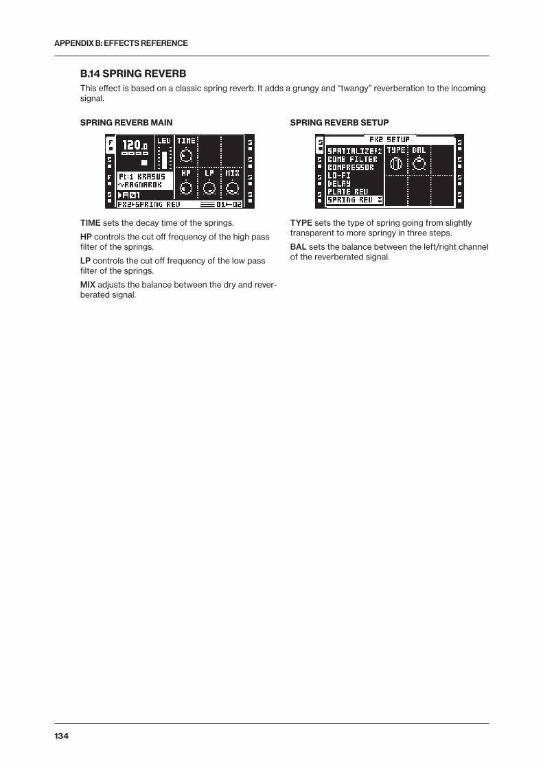
APPENDIX B: EFFECTS REFERENCE
134
B.14 SPRING REVERBThis effect is based on a classic spring reverb. It adds a grungy and “twangy” reverberation to the incoming signal.
SPRING REVERB MAIN
TIME sets the decay time of the springs.
HP controls the cut off frequency of the high pass filter of the springs.
LP controls the cut off frequency of the low pass filter of the springs.
MIX adjusts the balance between the dry and rever-berated signal.
SPRING REVERB SETUP
TYPE sets the type of spring going from slightly transparent to more springy in three steps.
BAL sets the balance between the left/right channel of the reverberated signal.
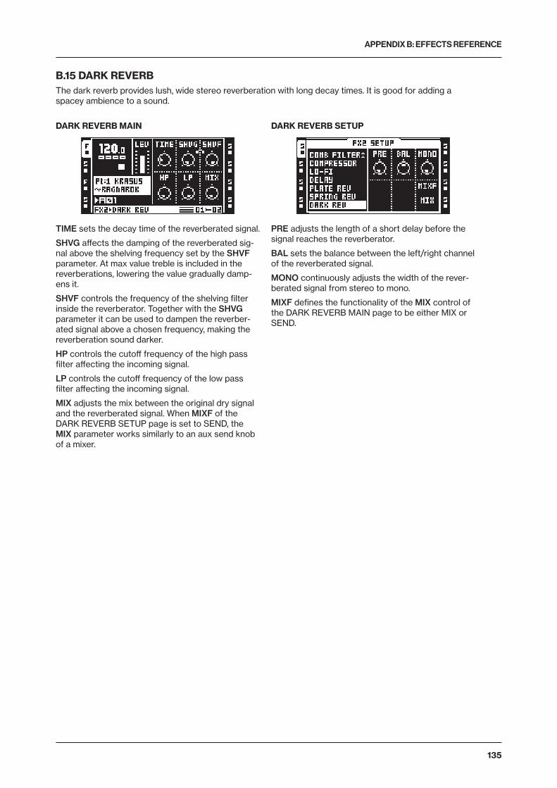
APPENDIX B: EFFECTS REFERENCE
135
B.15 DARK REVERBThe dark reverb provides lush, wide stereo reverberation with long decay times. It is good for adding a spacey ambience to a sound.
DARK REVERB MAIN
TIME sets the decay time of the reverberated signal.
SHVG affects the damping of the reverberated sig-nal above the shelving frequency set by the SHVF parameter. At max value treble is included in the reverberations, lowering the value gradually damp-ens it.
SHVF controls the frequency of the shelving filter inside the reverberator. Together with the SHVG parameter it can be used to dampen the reverber-ated signal above a chosen frequency, making the reverberation sound darker.
HP controls the cutoff frequency of the high pass filter affecting the incoming signal.
LP controls the cutoff frequency of the low pass filter affecting the incoming signal.
MIX adjusts the mix between the original dry signal and the reverberated signal. When MIXF of the DARK REVERB SETUP page is set to SEND, the MIX parameter works similarly to an aux send knob of a mixer.
DARK REVERB SETUP
PRE adjusts the length of a short delay before the signal reaches the reverberator.
BAL sets the balance between the left/right channel of the reverberated signal.
MONO continuously adjusts the width of the rever-berated signal from stereo to mono.
MIXF defines the functionality of the MIX control of the DARK REVERB MAIN page to be either MIX or SEND.
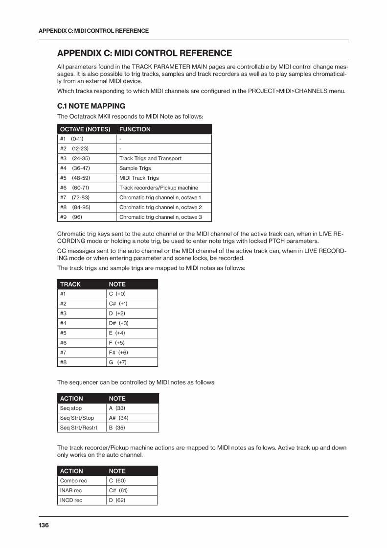
APPENDIX C: MIDI CONTROL REFERENCE
136
APPENDIX C: MIDI CONTROL REFERENCEAll parameters found in the TRACK PARAMETER MAIN pages are controllable by MIDI control change mes-sages. It is also possible to trig tracks, samples and track recorders as well as to play samples chromatical-ly from an external MIDI device.
Which tracks responding to which MIDI channels are configured in the PROJECT>MIDI>CHANNELS menu.
C.1 NOTE MAPPINGThe Octatrack MKII responds to MIDI Note as follows:
OCTAVE (NOTES) FUNCTION
#1 (0-11) -
#2 (12-23) -
#3 (24-35) Track Trigs and Transport
#4 (36-47) Sample Trigs
#5 (48-59) MIDI Track Trigs
#6 (60-71) Track recorders/Pickup machine
#7 (72-83) Chromatic trig channel n, octave 1
#8 (84-95) Chromatic trig channel n, octave 2
#9 (96) Chromatic trig channel n, octave 3
Chromatic trig keys sent to the auto channel or the MIDI channel of the active track can, when in LIVE RE-CORDING mode or holding a note trig, be used to enter note trigs with locked PTCH parameters.
CC messages sent to the auto channel or the MIDI channel of the active track can, when in LIVE RECORD-ING mode or when entering parameter and scene locks, be recorded.
The track trigs and sample trigs are mapped to MIDI notes as follows:
TRACK NOTE
#1 C (+0)
#2 C# (+1)
#3 D (+2)
#4 D# (+3)
#5 E (+4)
#6 F (+5)
#7 F# (+6)
#8 G (+7)
The sequencer can be controlled by MIDI notes as follows:
ACTION NOTE
Seq stop A (33)
Seq Strt/Stop A# (34)
Seq Strt/Restrt B (35)
The track recorder/Pickup machine actions are mapped to MIDI notes as follows. Active track up and down only works on the auto channel.
ACTION NOTE
Combo rec C (60)
INAB rec C# (61)
INCD rec D (62)
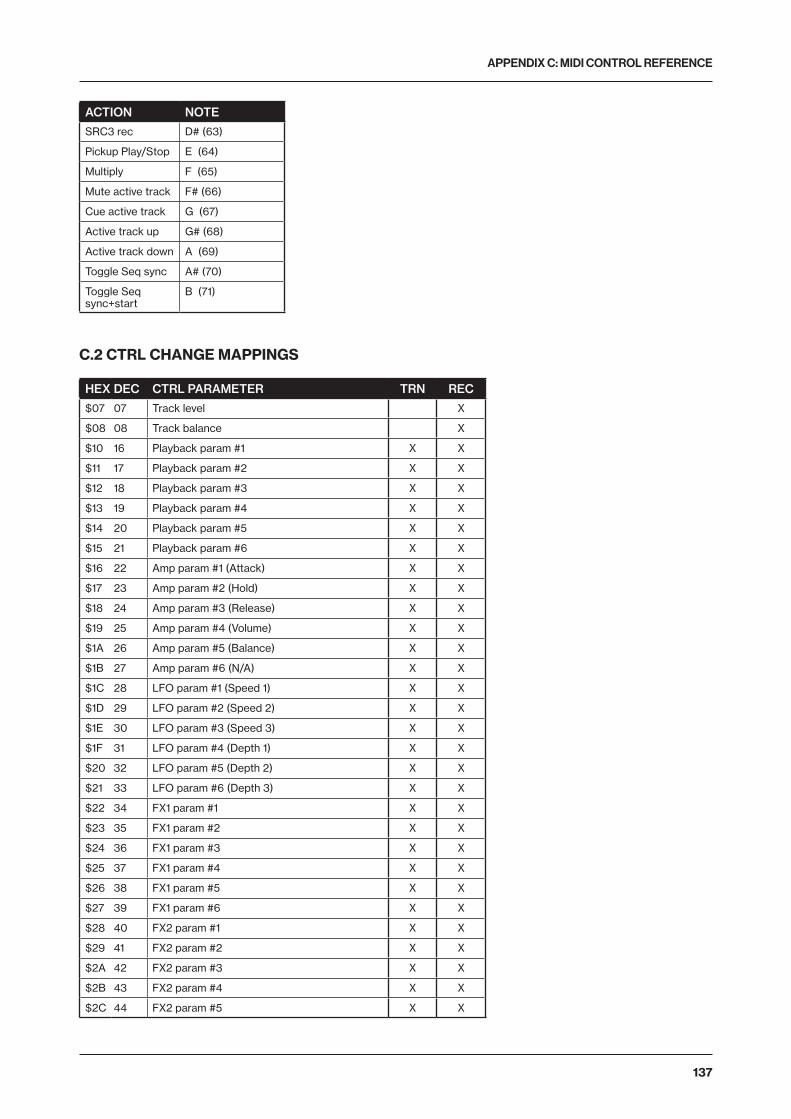
APPENDIX C: MIDI CONTROL REFERENCE
137
ACTION NOTE
SRC3 rec D# (63)
Pickup Play/Stop E (64)
Multiply F (65)
Mute active track F# (66)
Cue active track G (67)
Active track up G# (68)
Active track down A (69)
Toggle Seq sync A# (70)
Toggle Seq sync+start
B (71)
C.2 CTRL CHANGE MAPPINGS
HEX DEC CTRL PARAMETER TRN REC
$07 07 Track level X
$08 08 Track balance X
$10 16 Playback param #1 X X
$11 17 Playback param #2 X X
$12 18 Playback param #3 X X
$13 19 Playback param #4 X X
$14 20 Playback param #5 X X
$15 21 Playback param #6 X X
$16 22 Amp param #1 (Attack) X X
$17 23 Amp param #2 (Hold) X X
$18 24 Amp param #3 (Release) X X
$19 25 Amp param #4 (Volume) X X
$1A 26 Amp param #5 (Balance) X X
$1B 27 Amp param #6 (N/A) X X
$1C 28 LFO param #1 (Speed 1) X X
$1D 29 LFO param #2 (Speed 2) X X
$1E 30 LFO param #3 (Speed 3) X X
$1F 31 LFO param #4 (Depth 1) X X
$20 32 LFO param #5 (Depth 2) X X
$21 33 LFO param #6 (Depth 3) X X
$22 34 FX1 param #1 X X
$23 35 FX1 param #2 X X
$24 36 FX1 param #3 X X
$25 37 FX1 param #4 X X
$26 38 FX1 param #5 X X
$27 39 FX1 param #6 X X
$28 40 FX2 param #1 X X
$29 41 FX2 param #2 X X
$2A 42 FX2 param #3 X X
$2B 43 FX2 param #4 X X
$2C 44 FX2 param #5 X X
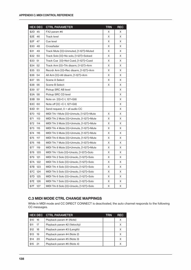
APPENDIX C: MIDI CONTROL REFERENCE
138
HEX DEC CTRL PARAMETER TRN REC
$2D 45 FX2 param #6 X X
$2E 46 Track level X X
$2F 47 Cue level X X
$30 48 Crossfader X X
$31 49 Track Mute [0]=Unmuted, [1-127]=Muted X X
$32 50 Track Solo [0]=No solo, [1-127]=Soloed X X
$33 51 Track Cue [0]=Not Cued, [1-127]=Cued X X
$34 52 Track Arm [0]=Trk disarm, [1-127]=Arm X X
$35 53 Recrdr Arm [0]=Rec disarm, [1-127]=Arm X X
$36 54 All Arm [0]=All disarm, [1-127]=Arm X X
$37 55 Scene A Select X X
$38 56 Scene B Select X X
$39 57 Pickup SRC AB level X
$3A 58 Pickup SRC CD level X
$3B 59 Note on [0]=C-1, 127=G9) X
$3C 60 Note off [0] =C-1, 127=G9) X
$3D 61 Send request, 0 = all audio CC X
$70 112 MIDI Trk 1 Mute [0]=Unmute, [1-127]=Mute X X
$71 113 MIDI Trk 2 Mute [0]=Unmute, [1-127]=Mute X X
$72 114 MIDI Trk 3 Mute [0]=Unmute, [1-127]=Mute X X
$73 115 MIDI Trk 4 Mute [0]=Unmute, [1-127]=Mute X X
$74 116 MIDI Trk 5 Mute [0]=Unmute, [1-127]=Mute X X
$75 117 MIDI Trk 6 Mute [0]=Unmute, [1-127]=Mute X X
$76 118 MIDI Trk 7 Mute [0]=Unmute, [1-127]=Mute X X
$77 119 MIDI Trk 8 Mute [0]=Unmute, [1-127]=Mute X X
$78 120 MIDI Trk 1 Solo [0]=Unsolo, [1-127]=Solo X X
$79 121 MIDI Trk 2 Solo [0]=Unsolo, [1-127]=Solo X X
$7A 122 MIDI Trk 3 Solo [0]=Unsolo, [1-127]=Solo X X
$7B 123 MIDI Trk 4 Solo [0]=Unsolo, [1-127]=Solo X X
$7C 124 MIDI Trk 5 Solo [0]=Unsolo, [1-127]=Solo X X
$7D 125 MIDI Trk 6 Solo [0]=Unsolo, [1-127]=Solo X X
$7E 126 MIDI Trk 7 Solo [0]=Unsolo, [1-127]=Solo X X
$7F 127 MIDI Trk 8 Solo [0]=Unsolo, [1-127]=Solo X X
C.3 MIDI MODE CTRL CHANGE MAPPINGSWhile in MIDI mode and CC DIRECT CONNECT is deactivated, the auto channel responds to the following CC messages.
HEX DEC CTRL PARAMETER TRN REC
$10 16 Playback param #1 (Note) X
$11 17 Playback param #2 (Velocity) X
$12 18 Playback param #3 (Length) X
$13 19 Playback param #4 (Note 2) X
$14 20 Playback param #5 (Note 3) X
$15 21 Playback param #6 (Note 4) X

APPENDIX C: MIDI CONTROL REFERENCE
139
HEX DEC CTRL PARAMETER TRN REC
$16 22 Amp param #1 (Transpose) X
$17 23 Amp param #2 (Legato) X
$18 24 Amp param #3 (Mode) X
$19 25 Amp param #4 (Speed) X
$1A 26 Amp param #5 (Octave Range) X
$1B 27 Amp param #6 (Arp Note Length) X
$1C 28 MIDI LFO param #1 (Speed 1) X
$1D 29 MIDI LFO param #2 (Speed 2) X
$1E 30 MIDI LFO param #3 (Speed 3) X
$1F 31 MIDI LFO param #4 (Depth 1) X
$20 32 MIDI LFO param #5 (Depth 2) X
$21 33 MIDI LFO param #6 (Depth 3) X
$22 34 Pitch bend X
$23 35 Aftertouch X
$24 36 CC #1 param X
$25 37 CC #2 param X
$26 38 CC #3 param X
$27 39 CC #4 param X
$28 40 CC #5 param X
$29 41 CC #6 param X
$2A 42 CC #7 param X
$2B 43 CC #8 param X
$2C 44 CC #9 param X
$2D 45 CC #10 param X
$31 49 MIDI Track Mute [0]=Unmuted, [1-127]=Muted X
$32 50 MIDI Track Solo [0]=No solo, [1-127]=Soloed X
$36 54 All Arm [0]=All disarm, [1-127]=Arm X
$37 55 Scene A Select X
$38 56 Scene B Select X
$70 112 MIDI Trk 1 Mute [0]=Unmute, [1-127]=Mute X
$71 113 MIDI Trk 2 Mute [0]=Unmute, [1-127]=Mute X
$72 114 MIDI Trk 3 Mute [0]=Unmute, [1-127]=Mute X
$73 115 MIDI Trk 4 Mute [0]=Unmute, [1-127]=Mute X
$74 116 MIDI Trk 5 Mute [0]=Unmute, [1-127]=Mute X
$75 117 MIDI Trk 6 Mute [0]=Unmute, [1-127]=Mute X
$76 118 MIDI Trk 7 Mute [0]=Unmute, [1-127]=Mute X
$77 119 MIDI Trk 8 Mute [0]=Unmute, [1-127]=Mute X
$78 120 MIDI Trk 1 Solo [0]=Unsolo, [1-127]=Solo X
$79 121 MIDI Trk 2 Solo [0]=Unsolo, [1-127]=Solo X
$7A 122 MIDI Trk 3 Solo [0]=Unsolo, [1-127]=Solo X
$7B 123 MIDI Trk 4 Solo [0]=Unsolo, [1-127]=Solo X
$7C 124 MIDI Trk 5 Solo [0]=Unsolo, [1-127]=Solo X
$7D 125 MIDI Trk 6 Solo [0]=Unsolo, [1-127]=Solo X
$7E 126 MIDI Trk 7 Solo [0]=Unsolo, [1-127]=Solo X
$7F 127 MIDI Trk 8 Solo [0]=Unsolo, [1-127]=Solo X

INDEX
140
INDEX
AACCESSORIES 14
Carrying bag and protective lid 14Rack mount kit 14
AMPAmp main 58Amp setup 58
ARPEGGIATOR 91Setup 92
ARRANGER 86AUDIO EDITOR 79
Accessing 79Attributes 83Edit 82File 85Slice 80Trim 79
AUDIO FILE COMPATIBILITY 27AUDIO POOL 27
Adding content 27File compatibility 27
AUTO CHANNEL 41
BBANKS 52
CCARE INSTRUCTIONS 15CHROMATIC MODE 68CLEAR
Pattern 70Scene 54Track 71Track page 71Track parameter page 71Trig lock 72
COMPACT FLASH CARD 14Card tools 34Format card 35
CONDITIONAL LOCKS 76CONNECTING THE UNIT 15COPY
Pattern 70Scene 54Track page 71Track parameter page 71Trig 71
COPY, CLEAR AND PASTE 20CREDITS AND CONTACT INFORMATION 115CUE LEVEL 57CUE OUTPUTS 62
DDELAY COMPENSATE 36
EEARLY STARTUP MENU 111EFFECTS
Effects reference 121Track effects 61
ELECTRICAL SPECIFICATIONS 115EMPTY RESET 111
FFILE BROWSER 30FILL MODE 76FLEX AND STATIC MACHINES 55
GGRID RECORDING MODE 65
LLEVELS
Cue level 57Track main level 57
LFOLFO designer 61LFO main 59LFO setup 60
LIVE RECORDING MODE 65LOADING SAMPLES 24, 29
MMAIN OUTPUTS 62MASTER TRACK 35METRONOME 39MICRO TIMING 75, 76MIDI
Auto channel 41Clock receive 40Clock send 40Settings 39Transport receive 40Transport send 40Trig channel 41
MIDI CC LEARN 93MIDI CONTROL REFERENCE 136MIDI SEQUENCER 89
Accessing 89MIDI mode live recording/parameter locking 90MIDI routing 89MIDI track parameter pages 90
MIDI TRACK PARAMETERS 90Arpeggiator main 91Arpeggiator setup 92CTRL 1 main 93CTRL 1 setup 93CTRL 2 main 93CTRL 2 setup 94
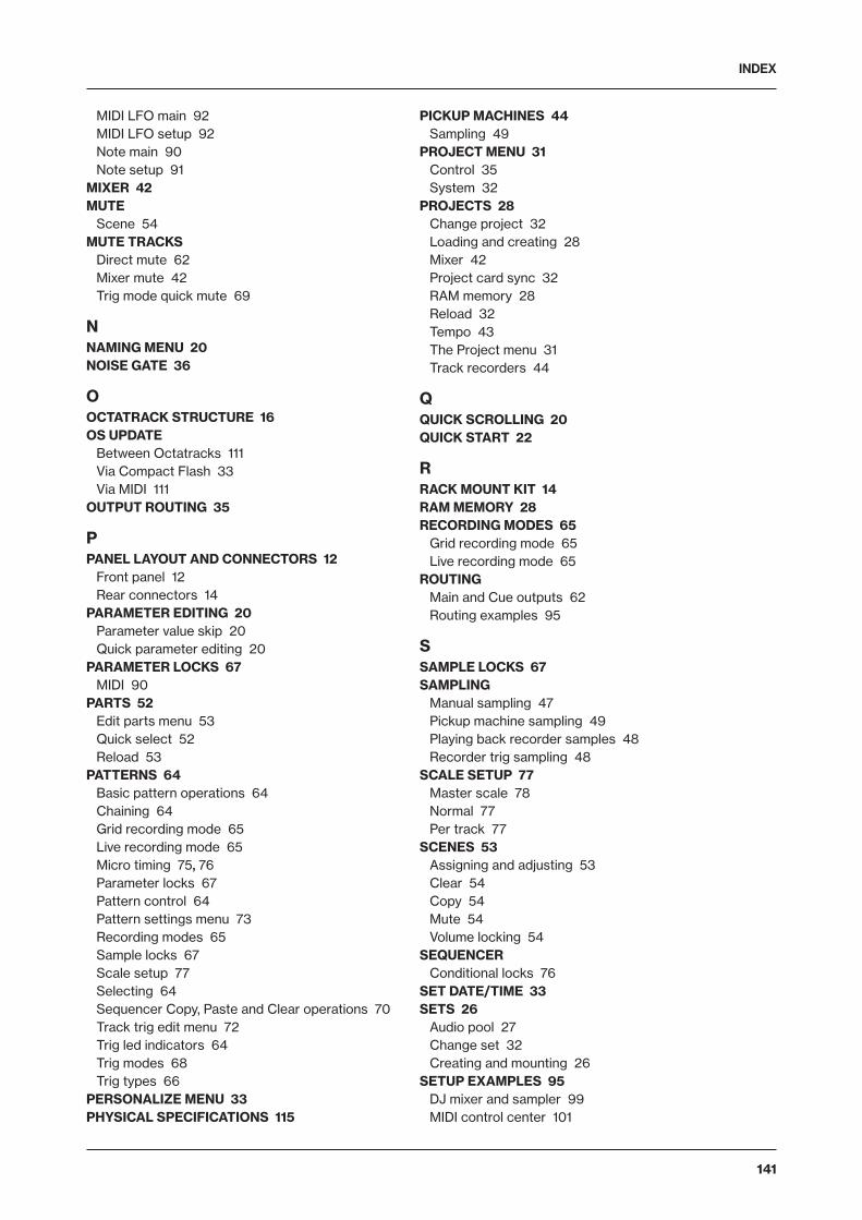
INDEX
141
MIDI LFO main 92MIDI LFO setup 92Note main 90Note setup 91
MIXER 42MUTE
Scene 54MUTE TRACKS
Direct mute 62Mixer mute 42Trig mode quick mute 69
NNAMING MENU 20NOISE GATE 36
OOCTATRACK STRUCTURE 16OS UPDATE
Between Octatracks 111Via Compact Flash 33Via MIDI 111
OUTPUT ROUTING 35
PPANEL LAYOUT AND CONNECTORS 12
Front panel 12Rear connectors 14
PARAMETER EDITING 20Parameter value skip 20Quick parameter editing 20
PARAMETER LOCKS 67MIDI 90
PARTS 52Edit parts menu 53Quick select 52Reload 53
PATTERNS 64Basic pattern operations 64Chaining 64Grid recording mode 65Live recording mode 65Micro timing 75, 76Parameter locks 67Pattern control 64Pattern settings menu 73Recording modes 65Sample locks 67Scale setup 77Selecting 64Sequencer Copy, Paste and Clear operations 70Track trig edit menu 72Trig led indicators 64Trig modes 68Trig types 66
PERSONALIZE MENU 33PHYSICAL SPECIFICATIONS 115
PICKUP MACHINES 44Sampling 49
PROJECT MENU 31Control 35System 32
PROJECTS 28Change project 32Loading and creating 28Mixer 42Project card sync 32RAM memory 28Reload 32Tempo 43The Project menu 31Track recorders 44
QQUICK SCROLLING 20QUICK START 22
RRACK MOUNT KIT 14RAM MEMORY 28RECORDING MODES 65
Grid recording mode 65Live recording mode 65
ROUTINGMain and Cue outputs 62Routing examples 95
SSAMPLE LOCKS 67SAMPLING
Manual sampling 47Pickup machine sampling 49Playing back recorder samples 48Recorder trig sampling 48
SCALE SETUP 77Master scale 78Normal 77Per track 77
SCENES 53Assigning and adjusting 53Clear 54Copy 54Mute 54Volume locking 54
SEQUENCERConditional locks 76
SET DATE/TIME 33SETS 26
Audio pool 27Change set 32Creating and mounting 26
SETUP EXAMPLES 95DJ mixer and sampler 99MIDI control center 101
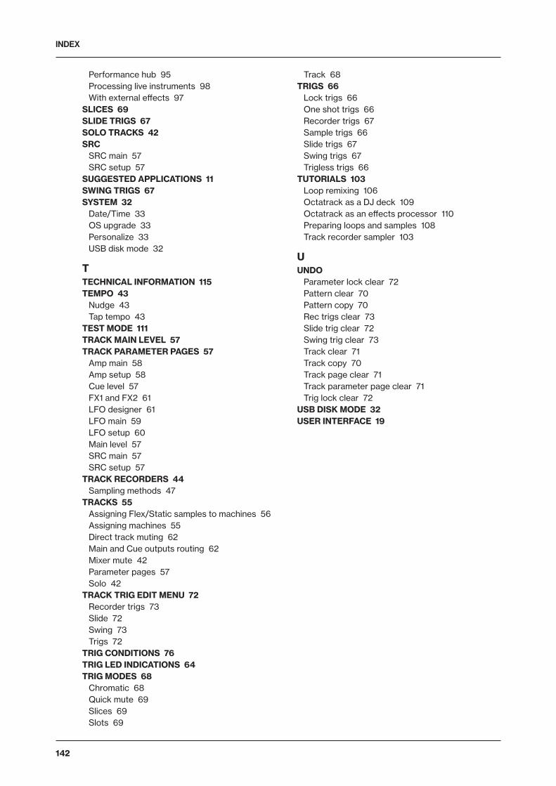
INDEX
142
Performance hub 95Processing live instruments 98With external effects 97
SLICES 69SLIDE TRIGS 67SOLO TRACKS 42SRC
SRC main 57SRC setup 57
SUGGESTED APPLICATIONS 11SWING TRIGS 67SYSTEM 32
Date/Time 33OS upgrade 33Personalize 33USB disk mode 32
TTECHNICAL INFORMATION 115TEMPO 43
Nudge 43Tap tempo 43
TEST MODE 111TRACK MAIN LEVEL 57TRACK PARAMETER PAGES 57
Amp main 58Amp setup 58Cue level 57FX1 and FX2 61LFO designer 61LFO main 59LFO setup 60Main level 57SRC main 57SRC setup 57
TRACK RECORDERS 44Sampling methods 47
TRACKS 55Assigning Flex/Static samples to machines 56Assigning machines 55Direct track muting 62Main and Cue outputs routing 62Mixer mute 42Parameter pages 57Solo 42
TRACK TRIG EDIT MENU 72Recorder trigs 73Slide 72Swing 73Trigs 72
TRIG CONDITIONS 76TRIG LED INDICATIONS 64TRIG MODES 68
Chromatic 68Quick mute 69Slices 69Slots 69
Track 68TRIGS 66
Lock trigs 66One shot trigs 66Recorder trigs 67Sample trigs 66Slide trigs 67Swing trigs 67Trigless trigs 66
TUTORIALS 103Loop remixing 106Octatrack as a DJ deck 109Octatrack as an effects processor 110Preparing loops and samples 108Track recorder sampler 103
UUNDO
Parameter lock clear 72Pattern clear 70Pattern copy 70Rec trigs clear 73Slide trig clear 72Swing trig clear 73Track clear 71Track copy 70Track page clear 71Track parameter page clear 71Trig lock clear 72
USB DISK MODE 32USER INTERFACE 19

INDEX
143

7112
EN
G-B