october 15, 2020 - reliving radio
TRANSCRIPT

Autumn of the year - Edition #9
O c t o b e r 1 5 , 2 0 2 0
Homer Price with an All American Five

Bald Letter October 15, 2020
1
Happy Halloween- from the
pumpkin patch,- An illustration by
Robert McCloskey from the
children’s book, The Man Who
Lost His Head written by Claire
Huchet Bishop published in 1942.
2020 Virus Edition #9 Table of Contents De Forest RadioHome TD-700 ....................................................2 Quarantine Show and Tell ............................................................3 The POW canteen Radio ..............................................................4 A History Lesson from Pete Petersen ...........................................7 Vanishing AM station ..................................................................9 Technical Talk “Where’s the Oscillator?” .................................10 The Radio Beginner - Foxhole Radio .......................................13
This is the ninth issue of a fun history hobby e-letter. Share it and pass it around. It’s free. It’s for fun.
Go to www.relivingradio.com for past issues of the Bald Letter. Help yourself and forward them to others. They’re FREE.
The Bald Letter is the work of Dick Karman who is solely responsible for its content. He would welcome your comments, complaints and corrections. [email protected]
Summer has changed to Fall and many of our normal activities have changed from years past. Even something as enjoyable as meeting for a cup of coffee and a donut isn’t as enjoyable any more. So while we’re home watching the leaves turn, read about radio and remember the way radio (and life) used to be.
Thanks to Dave Wise, Chris Butler, the late Pete Petersen, The Colorado Radio Collectors, The New England Vintage Electronics Club, the late Robert McCloskey, and The Puget Sound Antique Radio Society.
The Bald Letter is distributed on the 15th of each month, knowing that what we are experiencing is but a momentary light affliction. [DK]
2 Corinthians 4:17-18

Bald Letter October 15, 2020
2
Your editor recently examined and appreciated a collection of early De Forest radio apparatus. Most of the pieces were either in excellent original shape or nicely restored.
The card that appears above was displayed in the lid of a De Forest RadioHome type DT-700. The apparatus was surprisingly simple, with one tube and plug-in coils to vary the bands. This instruction card, I am told because it had still discernable red ink, was most probably a reproduction (an original from 1922 would have been faded 98 years later).
Displaying images like knob instruction cards, antenna hook up schematics, battery placement charts and tube diagrams with your sets on display makes each set look like the day it was taken home for the first time. It is always a “nice touch.”

Bald Letter October 15, 2020
3
Quarantine Show and Tell From Chris Butler as told to Dick Karman
Your editor recently caught up with Chris Butler of Lynchburg, Virginia. Chris is a vintage radio collector and was an active contributor to the Northwest Vintage Radio Society, in Oregon. A few years back he moved from the Pacific Northwest to Virginia to be closer to his children after the unexpected death of his wonderful wife. For
those of you who know Chris from his associations in Washington and Oregon he says hello and “the family is doing well.”
This show and tell contribution was constructed while Chris was in the Northwest and was a “hands-on” demonstration at one of the meetings in Portland. Although it is not necessarily “vintage” it does replicate a vintage set from the war years and is marvelously simple, but in its own way, rather complex. The complexity was that it had to be concealed as a canteen in plain sight every day. And parts for construction had to be scrounged from any number of sources without the camp guards’ knowledge.
There are several accounts of the POW short wave radio to be found on the internet. Some of those are sources that Chris used and are listed at the end of his article (start on page 4). The amazement I share with many others is that the prisoners in the camps didn’t start with a tech bench, tools, a meter and a soldering iron. They started with whatever they could hide under their mattress, and what they could steal from their captors.
Thanks Chris for reminding us why we often refer to them as the greatest generation.

Bald Letter October 15, 2020
4
A POW Canteen SW Receiver By Chris Butler, Virginia
My frequent research into the many facets of our hobby has led me down a variety of paths. One of them a few years back was the intersection of World War II and radio. We are all familiar with the Signal Corp. and of course the all-encompassing “boat anchor” line of receivers, transmitters and transceivers. But what caught my eye was the various types of clandestine radios.
After research I knew I had to build replicas of a couple of the models. My first attempt was a replica of a “canteen radio,” while the second was the Whaddon Mk. VII “Paraset” radio.
Before going any further, I must make clear the majority of the following information is a summation of the work of Hiroki “Hiro” Kata, AH6CY, from an article first appearing in Electric Radio in the November, 2012 issue. All credit is due him and all errors in interpretation are mine.
In the Pacific theater at the beginning of WWII, the Allies were pushed back on their heels by the Japanese, especially in the Philippines. Many soldiers and civilians were taken captive and were interred in POW camps, one of which was Cabanatuan, where Lt. William D. Gibson was held. Lt. Gibson had come into possession of a 1-tube regenerative radio, having a dud tube, from Capt. Russell J. Hutchison, who had built the radio inside a GI canteen from scrap parts smuggled into the camp. Lt. Gibson replaced the bad tube and restored operation.
The radio/canteen hung in its web pouch from the end of his bed, with the Japanese being none the wiser. A wire antenna was fashioned and intertwined with a clothes line, hiding it from view, and headphones were hidden elsewhere in the camp. The prisoners operated the radio from a battery in the hospital building, listening at night to various stations from Saigon, Tokyo and even San Francisco!
As you can imagine they were not listening to Glen Miller’s greatest hits, but rather seeking information as to the Allies’ progress. The intent was to break out of the camp if the Allies were close, and to not allow the Japanese to exterminate them during their retreat. Indeed on 30 January 1945 the camp was

Bald Letter October 15, 2020
5
raided (The Great Raid) and the prisoners liberated, but the radio was lost.
Radios existed in many of the camps. Parts were manufactured or obtained by different methods. Initially, when the prisoners were first sent to the camps, many of the parts were smuggled in, hidden in their clothing. However, once these parts ran out, other methods were needed.
One account by former POW James Hildebrand tells of prisoners being summoned to fix Japanese radios. They would remove certain parts and say they were broken, and the Japanese would supply new ones without confiscating the old “broken” parts.
John A. Glusman writes “some prisoners scrounged copper, acid from a truck’s battery and zinc from trouser buttons to fashion a battery. Resistors were made from string covered in cinnamon bark, while capacitors were made from foil, paper and coconut oil.”
Tubes were smuggled in (under penalty of death!) or stolen from the Japanese. Power came from batteries to mains.
My own modern day endeavor had me taking a 1943 GI canteen and cutting out a section below the protruding weld lip, about 2/3 of the body. I used this piece as my “chassis” and after acquiring the appropriate parts (thank you fellow NW collectors, George Kirkwood and Blake Dietz!), set out on construction.

Bald Letter October 15, 2020
6
Schematics are available on the internet, and a lot of great info came from the Signal Corps: The Outcome.
I used a mixture of old and new parts, trying to stay with old on top and new underneath the chassis. A variety of tubes can be used, chiefly the 12SK7 and 6SK7, or a 6J7 (with some wiring changes). I used a 12SK7, mounting it perpendicular to the chassis. Others have mounted it parallel, having the end go up inside the neck of the canteen – there’s no right or wrong. I ran wires for both filament and plate to a ¼” female jack on the bottom of the canteen, the male end to my power supply. Others have put it out the side or actually through the mouth.
After completing construction – the moment of truth! I inserted headphones, attached my power supply and antenna, put the headphones on, AND – nothing. No stations were to be heard. I went over my wiring, and eventually Blake Dietz pointed out I had mis-wired the antenna variable tuning cap, basically shorting it to ground. FYI, this cap needs to be isolated from the chassis! Corrections made, preparations repeated, headphones on, AND – that pleasant squeal of regeneration and a station coming in! WWV at 5 Mc. I found I could only tune from about 4.5 Mc to 6.5 Mc. Some turns were removed from the coil and tuning expanded.
I was still experimenting, but I read of others who tuned from 3.5 Mc to 7.5 Mc. There is both chassis and hand capacitance which I tried to mitigate as well. In conclusion, I am amazed at the knowledge and ingenuity displayed by these and so many others, to construct something so useful under the harshest of conditions with the simplest of means. I hope this inspires you to also “give it a try” and wonder at their achievement.
• Resources: Electric Radio, ”Two Clandestine Radios of World War II,” Hiroki “Hiro” Kata, AH6CY, November, 2012
• Signal Corps: The Outcome (Mid-1943 through 1945), Thompson, George Rayner and Dixie R. Harris http://www.n6cc.com/canteen-radio-receiver
• http://www.skywaves.ar88.net/SPY/canteen_detail.htm See another war time DIY radio, Fox Hole Radios on page 13
Bald Letter October 15, 2020
7
The Alaska
Military Telegraph Service
A History Lesson penned by Pete Petersen WY7Z (silent Key)
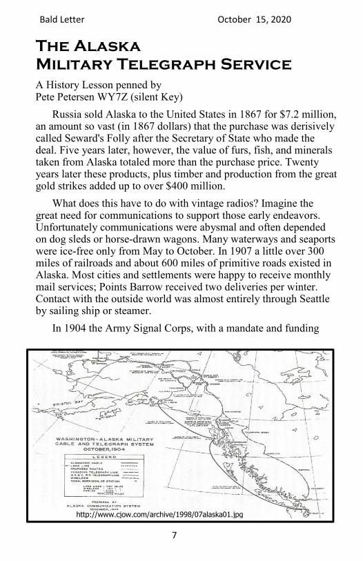
Russia sold Alaska to the United States in 1867 for $7.2 million, an amount so vast (in 1867 dollars) that the purchase was derisively called Seward's Folly after the Secretary of State who made the deal. Five years later, however, the value of furs, fish, and minerals taken from Alaska totaled more than the purchase price. Twenty years later these products, plus timber and production from the great gold strikes added up to over $400 million.
What does this have to do with vintage radios? Imagine the great need for communications to support those early endeavors. Unfortunately communications were abysmal and often depended on dog sleds or horse-drawn wagons. Many waterways and seaports were ice-free only from May to October. In 1907 a little over 300 miles of railroads and about 600 miles of primitive roads existed in Alaska. Most cities and settlements were happy to receive monthly mail services; Points Barrow received two deliveries per winter. Contact with the outside world was almost entirely through Seattle by sailing ship or steamer.
In 1904 the Army Signal Corps, with a mandate and funding
http://www.cjow.com/archive/1998/07alaska01.jpg

Bald Letter October 15, 2020
8
from Congress, began constructing a telegraph service for the military and also for army, civilian and commercial telegrams. An underwater cable was laid 3,000 miles from Seattle to Sitka, Ketchikan and Skagway. (The cable was extended a few years later to Valdez, Seward and Cordova.) 2,300 miles of landlines connected the cable to the interior, including Eagle (near what is now anchorage), Fairbanks, Tanana, and St Michael.
Railroad telegraph lines and several local, private telephone systems were connected to the Army system. A 1909 map shows that the system included eight wireless stations servicing areas too remote for landlines. The wireless link between St. Michael and Nome is credited to Captain L. Wildman who, as described by a writer of that time, "equipped, installed and operated a wireless system largely of his own invention."
The system was completed on time in 1908 and within its budget of $2.5 million. It was so extensive that about 75% of the white population (as statistics were kept and labeled) were within one hours travel of a telegraph office or telephone. Another 10% of the population were within fifty miles of such services. Even before completion of the system, annual tariffs from civilians and commercial telegrams amounted to $250,000 and service to government agencies and the military were valued at $100,000. These amounts increased rapidly and by the time the system was complete were valued at over $500,000 per year.
It would be interesting at this point to add something about the volume of telegrams handled or the cost per telegram, but that information is not included in my sources. I do, however, have a pamphlet entitled Rates of Pay for Communications By Telegraph published by the Postmaster General and dated August 5, 1893. Here are some selected examples: a day message cost 20 cents per 20 words if sent up to 1,000 miles; 40 cents per twenty words if sent over 3,000 miles. Comparable night messages were priced at 15 cents and 25 cents. Allowing for inflation from 1893 to 1908 and a large percentage of lengthier messages the system still had to handle an enormous amount of traffic to generate $900,000 in revenue.
The entire system was operated by one Signal Corps company of fewer than 200 men and a few officers. We can only guess the

Bald Letter October 15, 2020
9
long hours they must have worked and the primitive conditions they endured in what Robert Service described as "the land that God for-got."
It must be said to their credit that they often handled huge sums of cash, the most common means of payment then, with complete honesty. The Alaska Military Telegraph Service may have been the only project in the history of government to have been completed on time, under budget, -operated free of fraud and abuse, and provided a profit for the taxpayers.
Pete Petersen was a radio collector, a story teller, a Navy aviation
radioman in WWII and a past president of the Puget Sound Antique
Radio Association. He gave your editor this story and others for
publication in the 1990s. Many were fiction. This one is fact. They are all
cherished memories. He is missed. Pete became a silent key in May of
2016.
Vanishing AM radio
A few issues back your editor took an interest in program material that collectors could “reprogram” and listen to on their historical hardware. Adam of Seattle called our attention to an AM station that still sounds like an AM station. It’s commercial so the spots are as intrusive as commercial spots always have been, but it features hour-long broadcasts of radio shows from the golden age of radio, as well as “new radio” dramas (like Adventures of Harry Niles) and music features like The “50s at Five, and “Beatles Backbeat.” It is 880 KIXI and it streams so everyone can enjoy it. But more importantly, it is battling to stay alive. Sign up for its newsletter to show support for another
vanishing AM station. https://live.kixi.com/listen/

Bald Letter October 15, 2020
10
Where is the Oscillator?
A Technical Piece by Dave Wise, NWVRS Oregon
There is more to frequency conversion than meets the eye. The common description of the Superheterodyne receiver is that the oscillator is tuned 455 kHz above the antenna, and when the two mix, the result is (Osc - Ant) or the 455 kHz IF signal.
This is actually a special case, in three ways.
1. The IF need not be 455 kHz; that is just the most common choice for newer receivers. It can be literally anything, as long as it is above the highest audio frequency the station and receiver are designed to carry. The earliest ‘supers’ used various frequencies below 455: I’ve seen 50, 100, 175, and 262. A lot of mid-30’s Philcos used 470. The lower frequencies have the advantage that due to the relationship between Q, center frequency, and bandwidth, it is easier to get the necessary selectivity, even with the early crude manufacturing techniques; plus, the IF amplifier (if used) is more stable. On the other hand, it exacerbates the problem of “two-spot tuning”, and in addition results in undesirable interactions between the oscillator and mixer (known as “pulling”), especially when the two functions are combined in one tube. What is so special about 455? I don’t know, exactly; perhaps someone else can contribute here. However, it is a good compromise. You want to go as high as possible for image rejection (combating the “two spot” problem), but you have to stay below the broadcast range. Unless exquisitely shielded, receivers radiate like crazy at their IF, and any set that could tune to its own IF would hear nothing but its own regeneration. In the Portland, Oregon area, we can turn the choice of 455 to advantage when we do IF alignment with a signal generator of questionable accuracy. Simply tune a radio to 910, then tune the signal generator near 455 until you hear a beat note. Tune the generator until the beat note goes to zero - voila! The generator is exactly 455, half of 910.
Bald Letter October 15, 2020
11
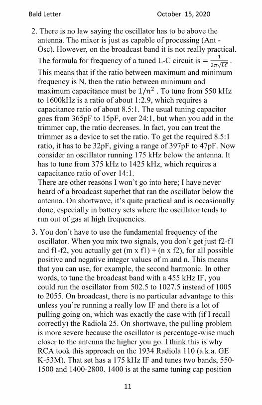
2. There is no law saying the oscillator has to be above the antenna. The mixer is just as capable of processing (Ant - Osc). However, on the broadcast band it is not really practical.
The formula for frequency of a tuned L-C circuit is =�
��√�� .
This means that if the ratio between maximum and minimum frequency is N, then the ratio between minimum and
maximum capacitance must be 1/� . To tune from 550 kHz to 1600kHz is a ratio of about 1:2.9, which requires a capacitance ratio of about 8.5:1. The usual tuning capacitor goes from 365pF to 15pF, over 24:1, but when you add in the trimmer cap, the ratio decreases. In fact, you can treat the trimmer as a device to set the ratio. To get the required 8.5:1 ratio, it has to be 32pF, giving a range of 397pF to 47pF. Now consider an oscillator running 175 kHz below the antenna. It has to tune from 375 kHz to 1425 kHz, which requires a capacitance ratio of over 14:1. There are other reasons I won’t go into here; I have never heard of a broadcast superhet that ran the oscillator below the antenna. On shortwave, it’s quite practical and is occasionally done, especially in battery sets where the oscillator tends to run out of gas at high frequencies.
3. You don’t have to use the fundamental frequency of the oscillator. When you mix two signals, you don’t get just f2-f1 and f1-f2, you actually get (m x f1) + (n x f2), for all possible positive and negative integer values of m and n. This means that you can use, for example, the second harmonic. In other words, to tune the broadcast band with a 455 kHz IF, you could run the oscillator from 502.5 to 1027.5 instead of 1005 to 2055. On broadcast, there is no particular advantage to this unless you’re running a really low IF and there is a lot of pulling going on, which was exactly the case with (if I recall correctly) the Radiola 25. On shortwave, the pulling problem is more severe because the oscillator is percentage-wise much closer to the antenna the higher you go. I think this is why RCA took this approach on the 1934 Radiola 110 (a.k.a. GE K-53M). That set has a 175 kHz IF and tunes two bands, 550-1500 and 1400-2800. 1400 is at the same tuning cap position

Bald Letter October 15, 2020
12
as 635, and 2800 is at 1420, so on BC, the oscillator is at 810 (for 635) and 1675 (for 1500), and on shortwave it is 787.5 (for 1400) and 1487.5 (for 2800).
Armed with this information, you can figure out the IF and oscillator scheme for just about any consumer radio. (Some of the ham sets use multiple levels of frequency conversion, and can’t be figured out without a manual.) Just use another radio (a ham set with decent frequency accuracy works great) as an RF “sniffer” to detect the RUT’s (radio under test’s) oscillator emissions. I just connect the two antenna leads together. DON’T DO THAT WITH AN AC-DC SET - use a small coupling cap instead. Listen for a strong unmodulated signal. At night, it will wipe out the background static. In the daytime, it is easier to tune the sniffer near a station and sweep the dial of the RUT. When the oscillator (or a harmonic of it) goes past the station, you’ll hear a beat note that falls in pitch to zero then rises again. At zero, the RUT’s oscillator is on the station frequency, or a sub-harmonic of it.
Note that the radio’s IF may have drifted over the years and not be quite on the intended frequency. I’ve seen this with both (mica) capacitively-tuned and (iron) inductively-tuned IF coils. This will affect tracking, and if at all possible, find out the proper frequency from service data and align it to that frequency.
Dave has been an active and contributing member of the NW Vintage Radio Society (Portland, Oregon) for many years. This is his autobiographical “long history in electronics.”
“I deviled my parents from a young age by taking apart anything that had more than one part, homed in on electricity by age ten (1969), went door to door begging vintage radios - this was the golden age of collecting - reached break-even (fix more than break) around age 15, found myself, even then, drawn to radios with interesting technological innovations or just plain quirks, and gradually shifted emphasis to vintage lab-grade test instruments and the odd iron-age computer (IBM 1620), which is where I'm at today.” - Dave

Bald Letter October 15, 2020
13
The Fox Hole Radio Receiver
The name was given during World War Two but the concept goes back to the first world war. The battlefield necessity was making a radio frequency receiving set out of immediately available parts in a hostile environment. Some newspaper reporter in 1944, dubbed it the Foxhole Radio. It was the essence of simplicity. GIs were not permitted other radios because it was believed that the regenerative and superheterodyne receivers of the time which radiated radio waves could give away their position to the enemy. Thus a crystal set was safe, and the “Foxhole Radio” was just a simplified crystal set. The most valued parts were the headphones and the disposable part was the “crystal” and coil.
There were conflicting reports about the origin of the design. The New York Times in April of 1944 credited Private Eldon Phelps, while one of the military communications of the day reported that Lieutenant. M. L. Rupert made the first receiver while he was attached to an infantry outfit serving on the Anzio beachhead in Italy. Though it undisputedly started in Europe, the concept quickly moved to the Pacific theater and around the world. It only picked up local broadcasts. Its receiving power was limited to the length of its antenna and therefore did not really work in a foxhole.
Building One:
Most radio beginners of 60 or 70 years ago began by making a crystal set. Understanding the work of the Crystal detector was the ‘mystery’ of the process, so if you were young, you followed instructions and marveled at the mystery. If you were in a war

Bald Letter October 15, 2020
14
and had a friend in the Signal Corp., you probably didn’t try to unravel the mystery, you took his word for it.
In a Foxhole Radio the “crystal” was a razor blade, and the “cat’s whisker” was the pinpoint of a safety pin. In the 1940s certain brand razor blades were distinguished by the name “blue blades.” Gillette coated their blades in blue lacquer to keep them from rusting, but they engraved their brand into the lacquer. (Today blades are coated with silicone and other substances that defeat the conductive characteristics.) The pinpoint connection between the safety pin and the razor blade was an imperfect connection and worked like the cat’s whisker on the surface of a crystal. To make it work it was sometimes necessary to ‘scratch’ around the brand name that was already engraved through the lacquer.
[To build a Foxhole Radio today, heat a razor blade with a butane lighter or propane torch until it turns red hot – then let it cool. It will thereafter act like a “blue blade.”]
There was still the need for the coil. It was determined that a hollow core of approximately 2 (or more) inches in diameter was best and that 120 turns was optimum. Today’s handyman finds a toilet paper tube to be about right. The wire was to be insulated, and No. 28 or 30 was adequate and maneuverable. After the 120 turns, don’t cut it off. Use the balance of your wire as your antenna. Most GIs didn’t have a reliable ground, so they connected the ground wire to their bayonet and drove it into wet earth. If the earth wasn’t wet, GIs had a way to add salty water and make it wet.
As those who are familiar with vintage radio will tell you the headphone is not only a listening device, but is also a critical part of the circuit. Many hobby booklets today specify a headphone, but fail to say that a high-impedance earpiece is preferable. In the 1940s the earpiece from a telephone was high-impedance and

Bald Letter October 15, 2020
15
worked well with a crystal set. In WWII a 1,000 ohm headset from an older radio was not that uncommon and was the one piece that the GI did not part with. It was noted that many Signal Corp men carried their own headsets with them and used them for their personal ‘foxhole’ receiver too. The rest of the receiver, the GI could throw into the fire or tread under foot, but the earpiece or headset, he tucked into his pack to use again.
Below is the “foxhole radio” used by Lt. M. L. Rupert in 1944.