odot pavement design guide -...
TRANSCRIPT

OODDOOTT PPAAVVEEMMEENNTT DDEESSIIGGNN GGUUIIDDEE
Pavement Services Unit December 2007

ODOT Pavement Design Guide Page i December 2007
ODOT PAVEMENT DESIGN GUIDE TABLE OF CONTENTS
Page USER RESPONSIBILITY......................................................................................................1 CHAPTER 1: INTRODUCTION .............................................................................................3 CHAPTER 2: PAVEMENT DESIGN PROCEDURES .................................................................5 CHAPTER 3: PROJECT SCOPE .............................................................................................7 CHAPTER 4: DATA COLLECTION.........................................................................................9
4.1 Office Information....................................................................................................... 9 4.1.1 Construction History.............................................................................................. 9 4.1.2 Pavement Condition .............................................................................................. 9 4.1.3 Traffic Data .......................................................................................................... 9
4.2 Field Reconnaissance ................................................................................................ 10 4.3 Field Investigation .................................................................................................... 10
4.3.1 Traffic Control..................................................................................................... 10 4.3.2 Deflections ......................................................................................................... 10
4.3.2.1 Asphalt Concrete Pavement .......................................................................... 11 4.3.2.2 Portland Cement Concrete Pavement ............................................................. 11 4.3.2.2.1 Continuously Reinforced Concrete Pavement.................................................. 12 4.3.2.2.2 Jointed Plain and Reinforced Concrete Pavement .......................................... 12 4.3.2.2.3 Composite Pavement ................................................................................ 12 4.3.2.2.4 Selection of Test Locations......................................................................... 13
4.3.3 Pavement Cores.................................................................................................. 13 4.3.4 Exploration Holes ................................................................................................ 14 4.3.5 Photographs of Roadway Condition ....................................................................... 14 4.3.6 Rut Depths......................................................................................................... 15 4.3.7 Bridge Approaches .............................................................................................. 15 4.3.8 Bridge Underpasses........................................................................................... 15 4.3.9 At-Grade Railroad Crossings ............................................................................... 16 4.3.10 Pavement Distress Surveys .............................................................................. 16
4.4 Laboratory Investigation............................................................................................ 17 4.4.1 Laboratory Tests ................................................................................................ 17 4.4.2 Testing Frequency.............................................................................................. 17
CHAPTER 5: DESIGN PROCEDURE INPUT PARAMETERS..................................................19 5.1 Traffic Analysis ......................................................................................................... 19
Table 1 – ESAL Annual Conversion Factors................................................................ 19 5.2 Subgrade Resilient Modulus (MR) ................................................................................ 20 5.3 Typical AASHTO Design Inputs ................................................................................... 21
5.3.1 Reliability ........................................................................................................... 21 Table 2 – Reliability Levels by Functional Class.......................................................... 21
5.3.2 Initial and Terminal Serviceability ......................................................................... 21 5.3.3 Overall Standard Deviation................................................................................... 22
5.4 Layer Coefficients for AASHTO Design Procedure .......................................................... 22 Table 3 – Layer Coefficient by Material Type ............................................................. 22
5.5 Drainage Coefficient.................................................................................................. 22 CHAPTER 6: NEW WORK AND RECONSTRUCTION DESIGN..............................................23
6.1 Asphalt Concrete Pavement Design Requirements ........................................................ 23 6.1.1 Minimum Design Life ........................................................................................... 23 6.1.2 Minimum AC Thickness ........................................................................................ 23

Page ii ODOT Pavement Design Guide December 2007
6.1.2.1 Structural Requirements................................................................................. 23 6.1.2.2 Shoulders..................................................................................................... 24
6.1.3 Roadway Widening.............................................................................................. 24 6.1.4 Joint Location ..................................................................................................... 24
6.2 Portland Cement Concrete Pavement Design Requirements ........................................... 25 6.2.1 Minimum Design Life ........................................................................................... 25 6.2.2 Minimum PCC Thickness ...................................................................................... 25 6.2.3 Roadway Widening.............................................................................................. 25 6.2.4 Joint Location and Spacing ................................................................................... 25 6.2.5 Design Details .................................................................................................... 26
6.2.5.1 Load Transfer................................................................................................ 26 6.2.5.2 Base/Subbase Materials ................................................................................. 27 6.2.5.3 Subdrainage ................................................................................................. 27 6.2.5.4 Shoulder ...................................................................................................... 28
6.3 Subgrade Improvement............................................................................................. 28 6.4 Design Alternatives ................................................................................................... 29 6.5 Special Considerations............................................................................................... 29
6.5.1 Bridge Approaches .............................................................................................. 29 6.5.2 Frost Design....................................................................................................... 29 6.5.3 Vertical Clearance At Bridge Underpasses .............................................................. 29
CHAPTER 7: REHABILITATION OF EXISTING PAVEMENT STRUCTURES..........................31 7.1 Design Life............................................................................................................... 31 7.2 Field Work ............................................................................................................... 32 7.3 Bridge Approaches.................................................................................................... 32 7.4 Vertical Clearance at Bridge Underpasses .................................................................... 32 7.5 Functional and Structural Pavement Conditions ............................................................ 33
7.5.1 Evaluation of Functional Condition......................................................................... 33 7.5.2 Evaluation of Structural Condition ......................................................................... 33
7.5.2.1 Non-Destructive Testing................................................................................. 33 Table 4 Deflection Data Analysis Results by Pavement Type........................................ 34
7.5.2.2 PCC Joint Load Transfer ................................................................................. 34 7.5.2.3 Remaining Life .............................................................................................. 34
7.6 Rehabilitation Design Alternatives............................................................................... 35 7.7 AC Pavement Rehabilitation ....................................................................................... 35
7.7.1 Structural Requirements for AC Overlay................................................................. 35 7.7.2 Pre-Overlay Repairs ............................................................................................ 35
7.7.2.1 Reflective Crack Control ................................................................................. 36 7.7.2.2 Cold Planing Guidelines .................................................................................. 37 7.7.2.3 AC Pavement Repair (Surfacing Stabilization) ................................................... 37
7.7.3 AC Pavement Over Cement Treated Base............................................................... 38 7.8 PCC Rehabilitation .................................................................................................... 39
7.8.1 Structural Requirements for PCC Pavement............................................................ 40 7.8.2 PCC Pavement Repairs......................................................................................... 40
7.8.2.1 Partial Depth Repairs ..................................................................................... 40 7.8.2.2 Full Depth Repairs ......................................................................................... 40 7.8.2.3 Other Repair or Maintenance Activities............................................................. 42
7.8.2.4 PCC Slab Void Detection.................................................................................... 42 7.8.2.5 Estimating Grout Quantities............................................................................ 43
7.8.3 HMAC Overlays................................................................................................... 44 7.8.4 Rubblization ....................................................................................................... 44
7.9 Reconstruction ......................................................................................................... 45 7.10 Life Cycle Cost Analysis ........................................................................................... 45

ODOT Pavement Design Guide Page iii December 2007
CHAPTER 8: BRIDGE APPROACH ANALYSIS AND DESIGN...............................................47 8.1 Preservation of AC Pavement Bridge Approaches.......................................................... 47 8.2 New Work Design of AC Pavement Bridge Approaches................................................... 48 8.3 Bridge Approaches Adjoining PCC Pavement ................................................................ 48
CHAPTER 9: LIFE CYCLE COST ANALYSIS ........................................................................51 9.1 Projects Requiring LCCA ............................................................................................ 51
9.1.1 New Pavement Construction................................................................................. 51 9.1.2 Pavement Rehabilitation or Reconstruction............................................................. 51
9.2 LCCA Methods .......................................................................................................... 52 9.3 General Approach to LCCA......................................................................................... 52 9.4 Analysis Period ......................................................................................................... 53 9.5 Discount Rates ......................................................................................................... 53 9.6 Establishing Strategies, Performance Periods and Activity Timing ................................... 53 9.7 Agency Costs ........................................................................................................... 54
9.7.1 Initial and Rehabilitation Project Costs ................................................................... 54 9.7.2 Maintenance Costs .............................................................................................. 54 9.7.3 Salvage Value..................................................................................................... 54
9.8 User Costs ............................................................................................................... 55 9.9 Interpreting and Presenting Results ............................................................................ 55
CHAPTER 10: MATERIALS ................................................................................................57 10.1 Asphalt Concrete Mix Type and Size Selection ............................................................ 57
10.1.1 Open Graded Hot Mixed Asphalt Concrete ............................................................ 57 10.1.2 Dense Graded Hot Mix Asphalt Concrete .............................................................. 58 10.1.3 Emulsified Asphalt Concrete................................................................................ 60 10.1.5 Chip Seals ........................................................................................................ 61
10.2 Mix Design Levels ................................................................................................... 61 10.2.1 Level 1............................................................................................................. 62 10.2.2 Level 2............................................................................................................. 62 10.2.3 Level 3............................................................................................................. 62 10.2.4 Level 4............................................................................................................. 62
10.3 PG Asphalt Binder Grades ........................................................................................ 63 10.3.1 Grade Selection................................................................................................. 63 10.3.2 Traffic Speed Adjustments.................................................................................. 63 10.3.3 Traffic Volume Adjustments................................................................................ 64
10.5 Anti-Stripping Additives ........................................................................................... 64 Table 5 – Decision Matrix for Lime or Latex Treatment ............................................... 64
10.6 Aggregate Base ...................................................................................................... 65 10.7 Portland Cement Concrete ....................................................................................... 65
10.7.1 Continuously Reinforced Concrete Pavement ........................................................ 65 10.7.2 Jointed Reinforced Concrete Pavement ................................................................ 66 10.7.3 Jointed Plain Concrete Pavement......................................................................... 66
10.8 Geosynthetics......................................................................................................... 66 CHAPTER 11: CONSTRUCTION AND SPECIFICATIONS ....................................................69
11.1 Construction Considerations ..................................................................................... 69 11.1.1 Constructability................................................................................................. 69 11.1.2 Contract Documents .......................................................................................... 69
11.1.2.1 Project Specific Information .......................................................................... 69 11.1.2.2 Contract Plans............................................................................................. 70 11.1.2.3 Specifications.............................................................................................. 70
11.2 Asphalt Concrete Pavement...................................................................................... 71 11.2.1 Section 00745 – Hot Mix Asphalt Concrete (HMAC) ............................................... 71
11.2.1.1 Asphalt Cement Designation ......................................................................... 71

Page iv ODOT Pavement Design Guide December 2007
11.2.1.2 Pavement Smoothness................................................................................. 72 11.2.1.3 Material Transfer Device............................................................................... 72 11.2.1.4 Latex Polymer Treatment Option ................................................................... 72 11.2.1.5 Fiber Stabilizing Additive Option .................................................................... 72
11.2.2 Section 00744 – Minor Hot Mixed Asphalt Concrete Pavement ................................ 73 11.2.3 Section 00735 – Emulsified Asphalt Concrete Pavement......................................... 73
11.3 Aggregate Base ...................................................................................................... 74 11.3.1 Section 00641 – Aggregate Subbase, Base, and Shoulders..................................... 74 11.3.2 Section 00640 – Aggregate Base and Shoulders (Small Quantities) ......................... 74
11.4 Subgrade Improvement........................................................................................... 75 11.4.1 Section 00331 – Subgrade Stabilization ............................................................... 75 11.4.2 Section 00344 – Treated Subgrade...................................................................... 75
11.5 Asphalt Concrete Pavement Repair (Surfacing Stabilization)......................................... 75 11.6 Portland Cement Concrete Pavement ........................................................................ 76
11.6.1 Section 00755 – Continuously Reinforced Concrete Pavement ................................ 76 11.6.2 Section 00756 – Plain Concrete Pavement............................................................ 76 11.6.3 SP00758 – Concrete Repairs............................................................................... 76
11.7 Subgrade Geotextile................................................................................................ 77 CHAPTER 12: DELIVERABLES...........................................................................................79
12.1 FWD Calibration Requirements ................................................................................. 79 12.2 Design Report and Supporting Documentation............................................................ 79
12.2.1 Executive Summary........................................................................................... 80 12.2.2 Supporting Documentation ................................................................................. 80 12.2.3 Electronic Files .................................................................................................. 81 12.2.4 Deliverable Checklist.......................................................................................... 81
APPENDIX A Pavement Design Procedure Contact Information............................................................... 85
APPENDIX B Project Prospectus Example............................................................................................. 87
APPENDIX C Pavement Depth Core Log............................................................................................... 93
APPENDIX D Exploration Hole Log....................................................................................................... 99
APPENDIX E Bridge Approach Testing ................................................................................................103
APPENDIX F At-Grade Railroad Crossing Testing .................................................................................105
APPENDIX G Objective Rating Distress Type Descriptions....................................................................107
APPENDIX H Sample Distress Rating Form..........................................................................................121
APPENDIX I Example ESAL Calculation ..............................................................................................123
APPENDIX J Mix Type and PG Binder Recommendation........................................................................125
APPENDIX K Executive Summary.......................................................................................................131
APPENDIX L Glossary of Terms .........................................................................................................135
APPENDIX M Deliverables Checklist ....................................................................................................137

ODOT Pavement Design Guide Page 1 December 2007
OREGON DEPARTMENT OF TRANSPORTATION PAVEMENT DESIGN GUIDE
December 2007
USER RESPONSIBILITY The Oregon Department of Transportation (ODOT) Pavement Design Guide will be updated periodically to remain current with ODOT design, Specification, and construction policies. When necessary, the guide will also be updated to reflect changes or developments in industry practices, procedures and materials. When updates are made, the date indicated on the cover sheet of the design guide will be changed to reflect when the changes were made. Since the design guide can be downloaded at any time from the ODOT website, ODOT will not attempt to track the identity of all users of this guide. Therefore it is the responsibility of the user to confirm that they are using the current version of the ODOT Pavement Design Guide.

Page 2 ODOT Pavement Design Guide December 2007
This page intentionally left blank.

ODOT Pavement Design Guide Page 3 December 2007
CHAPTER 1: INTRODUCTION The purpose of the ODOT Pavement Design Guide (PDG) is to provide a summation of design requirements for use by ODOT personnel and private consultants (Contractors) who are engaged in the preparation of pavement designs for projects administered through the Oregon Department of Transportation (ODOT). Throughout this guide, there are references to responsibilities of the “Designer”. Designer means the ODOT technical staff responsible for pavement designs for “in-house” projects completed by ODOT. For out-sourced projects, “Designer” means the professional consultant under contract to provide pavement design services for projects administered through ODOT. The design guide provides information on many topics including but not limited to:
• Acceptable Pavement Design Procedures • Data Collection for Pavement Design • Guidelines for New Work Sections and Reconstruction • Guidelines for Pavement Rehabilitation • Life Cycle Costs Analysis • Materials and Specifications • Documentation and Deliverables
The intent of this document is to provide general guidance and outline the minimum acceptable standards for design analysis and supporting documentation for pavement Designers. The PDG allows for engineering judgement to be applied on a project basis; however, deviations from the guide must be justified, and in some cases prior approval obtained from ODOT Pavement Services. The ODOT Pavement Design Engineer, or other qualified staff member, will review all pavement designs for structural adequacy and compliance with the guidelines set forth in this document. The user should keep in mind that this document is under development and will be updated periodically as required. It is our intention that, as time permits, the document will be expanded to provide additional information. We welcome any comments or suggestions you may have for improving this guide. Specification references are based on the Oregon Standard Specifications for Construction, 2002, unless otherwise noted. The Standard Drawings and Standard Details are referenced based on the numbers at the time of guide publication. This guide has been formatted for double-sided printing. Questions regarding any of the information presented in this guide may be directed to: Pavement Services Unit 503-986-3000 Copies of the ODOT Pavement Design Guide can be obtained online at:
http://www.oregon.gov/ODOT/HWY/CONSTRUCTION/PSIndex.shtml

Page 4 ODOT Pavement Design Guide December 2007
This page intentionally left blank.

ODOT Pavement Design Guide Page 5 December 2007
CHAPTER 2: PAVEMENT DESIGN PROCEDURES All pavement designs for State Highways must use the most cost-effective design that meets the objectives of the project and all applicable design standards. All pavement designs for State Highways must be developed using a recognized design procedure. Examples of acceptable procedures include, but are not exclusive to:
• 1993 AASHTO Guide for Design of Pavement Structures and Supplements • The Asphalt Institute • Portland Cement Association • Asphalt Pavement Association of Oregon (APAO) (based on AASHTO) • American Concrete Pavement Association
Appendix A contains contact information if you would like to get more information on these pavement design procedures. There is no universally accepted pavement design procedure. The list above is intended only to give the reader an example of those procedures available. The use of other procedures not listed above must be approved in advance and in writing (email acceptable) by the ODOT Pavement Design Engineer. Whichever procedure is used, it is important that the pavement design meet the requirements outlined in the following chapters. For non-state highway applications up to 1 million ESALs a procedure such as the one demonstrated in the APAO Asphalt Paving Design Guide or the AASHTO Low Volume procedure may be used. The APAO Design Guide is the preferred procedure for applications where the anticipated ESAL level is 50,000 or less. It is not acceptable for most state highway projects including large projects or for bridge end reconstruction work on the state highway system. If the structural section design recommendation for a non-state highway is based on a local agency standard, the standard must be checked using a nationally recognized pavement design procedure. This check is required to make sure the design standard is applicable to the present situation. If the local agency has a functional Pavement Management System and can provide actual performance data (for ODOT review) to justify the design, this may be accepted in place of using the design procedure verification. Multi-use paths for bikes and pedestrians separated from the roadway do not require a pavement design report. However, a requested design of roadway shoulders to a reduced thickness, such as for bike lanes, may be considered within a pavement design report. Multi-use paths should be engineered and designed using guidance from the Oregon Bicycle and Pedestrian Plan, found at:
http://egov.oregon.gov/ODOT/HWY/BIKEPED/planproc.shtml In addition, use best engineering practices including those documented in the APAO Asphalt Paving Design Guide.

Page 6 ODOT Pavement Design Guide December 2007
This page intentionally left blank.

ODOT Pavement Design Guide Page 7 December 2007
CHAPTER 3: PROJECT SCOPE The project scope is a description of the parameters of the project and can be found in the project prospectus. The prospectus defines the problem the project is intended to address along with the proposed solution, project limits, and funding information. The Prospectus is developed at the time of the project’s initial conception. In many instances, the scope can be developed as far as 4 to 6 years in advance of construction. The proposed solution for Pavement Preservation type projects is based on an assessment of the condition of the pavement and the construction history at the time of project conception. It is meant as an estimate only, to be used for budgeting purposes, and should not be construed as a final pavement design recommendation. An example prospectus can be found in Appendix B. During project development the scope can change as new information is obtained. It is important for the ODOT Designer to keep in contact with the Project Leader; or in the case of consultant designers, the Consultant Project Manager (or Work Order Contract Manager).

Page 8 ODOT Pavement Design Guide December 2007
This page intentionally left blank.

ODOT Pavement Design Guide Page 9 December 2007
CHAPTER 4: DATA COLLECTION This chapter provides guidance on data collection and covers both office and field data collection. The intent of this chapter is to provide resource information such as what is available and how to obtain information such as construction history, pavement condition, and traffic data, as well as guidance on the minimum acceptable levels of field work required for the development of pavement designs.
4.1 Office Information
4.1.1 CONSTRUCTION HISTORY Construction history information is important in developing pavement designs. Construction history is useful in developing a field investigation strategy, determining the existing material types and depths, and evaluating the performance of existing materials. ODOT maintains a record of As-Constructed drawings commonly referred to as V-Files. Useful information from the V-Files includes the cover sheet, details, typical pavement sections and summary. V-File information can be obtained from the ODOT Roadway Engineering Section by sending a request to [email protected]. The V-Files are valuable resources, but the Designer is cautioned that the information contained in the files is not always complete. Also, maintenance preservation work is usually not included in the V-Files.
4.1.2 PAVEMENT CONDITION Another source of data is the ODOT Pavement Management System (PMS). The PMS can provide construction history and pavement condition information. Summary information for each section of highway can be obtained in the Pavement Condition Report that is available on-line at:
www.oregon.gov/ODOT/HWY/CONSTRUCTION/pavement_management_sys.shtml The report, published every odd year, provides condition information on each section of highway as well as information on the rating procedures used. Beginning in 2004, the Pavement Condition Report is published every even year.
4.1.3 TRAFFIC DATA Traffic data is a critical component of any pavement design analysis. This data typically consists of average annual daily traffic (AADT), an annual growth rate or expansion factor, and a percentage of the AADT in each of the 13 federally designated vehicle classes (axle categories). A more detailed discussion of the traffic data analysis is found in a later section. Traffic information can be obtained from the Transportation Planning Analysis Unit (TPAU) at 503-986-4251. It is required that the growth rate and traffic data for ESAL calculations be obtained from ODOT for each specific project requiring a pavement design. A phone call to TPAU will assure the appropriate traffic, axle distribution, and growth factors will be utilized.

Page 10 ODOT Pavement Design Guide December 2007
4.2 Field Reconnaissance Field reconnaissance is a site visit for the purpose of determining the type and extent of field investigation work required on the project and any specific locations the designer wants tested. In addition to planning the field investigation work, it gives the designer an opportunity to determine the requirements for traffic control during testing.
4.3 Field Investigation The intent of this section is to provide guidance on the type and extent of field investigation required for the development of pavement design recommendations. The guidance provided should be considered as a starting point and is intended to represent the minimum level of field investigation required. As each project will be unique, the field investigation plan must be adjusted to provide adequate information for evaluating the needs of the project. The following sub-sections outline the field investigation requirements for ODOT projects. Each sub-section discusses the requirements for a particular type of testing, such as deflections, cores, etc. ODOT defines new work as the construction of new pavement, including widening of existing facilities and new alignments. Pavement rehabilitation is defined as any work on an existing facility and includes work such as inlays, overlays, or reconstruction. A review of the project scope and a field reconnaissance are the first steps in developing the field investigation plan. The field reconnaissance provides the Designer with the opportunity to evaluate the project for what types of investigative work are required along with the testing and sampling locations and frequencies.
4.3.1 TRAFFIC CONTROL Traffic control must be conducted in accordance with the latest version of “Oregon Temporary Traffic Control Handbook” published by the Oregon Department of Transportation:
www.oregon.gov/ODOT/Hwy/Traffic-Roadway/publications_traffic.shtml In the case of Contractor field investigations, traffic control must be conducted in accordance with the contract documents.
4.3.2 DEFLECTIONS Deflections must be measured with a Falling Weight Deflectometer (FWD), in accordance with ASTM-D4694, applying loads to the pavement of approximately 6000, 9000, and 12,000 lb (26.7, 40.0, and 53.4 kN) and measuring the deflections in at least 7 locations. Sensors must be located per the Strategic Highway Research Program (SHRP) Guidelines of 0, 8, 12, 18, 24, 36, and 60 inches (0, 200, 300, 450, 600, 900, and 1500 mm ) from the center of the load cell for all deflection testing. Deviations from the above applied

ODOT Pavement Design Guide Page 11 December 2007
loads and sensor spacing must be approved in writing by the ODOT Pavement Design Engineer. The FWD must be calibrated routinely per the manufacturer's recommendations. In addition, the FWD load cells and sensors must be calibrated at a Regional Calibration Center within a 12 month period preceding the date of testing on a project. More information on FWD calibration can be found at:
SHRP/LTPP FWD CALIBRATION PROTOCOL Prior to beginning work on a project, and as needed or directed, the FWD's Distance Measurement Instrument must be calibrated to insure proper distance measurement. Deflection testing is not required for the construction of roadways on new alignments. However, deflection testing of adjacent roadways may provide data for the back-calculation of subgrade resilient modulus that may be appropriate for new work design. The designer must consider the most cost-effective means of obtaining the subgrade resilient modulus (see Section 5.2). Submit deflection data and analysis as well as FWD calibration information as per Chapter 12 of this guide.
4.3.2.1 Asphalt Concrete Pavement For widening of existing roadways consisting of asphalt concrete (AC) pavement, deflections must be measured on the shoulder at a maximum spacing of 250 ft (76 m) to help determine if the shoulders are structurally sufficient to carry travel lane traffic after widening (Refer to Section 6.1.4 for construction joint location requirements). If widening is only to increase shoulder width and will not carry travel lane loads, deflection testing is not required. If the existing pavement is to be structurally overlaid in addition to widening, deflection testing is required per the requirements outlined under the pavement rehabilitation portion of this sub-section. For pavement rehabilitation projects, deflections must be measured in the outer wheelpath of the most distressed lane. The maximum spacing for deflection testing must not exceed 250 ft (76 m). Consideration shall be given to reducing this spacing in urban areas or areas of localized structural failure. In highway sections of multi-lanes in the same direction, deflections must be taken in both travel directions in accordance with the above requirements. The Designer shall use professional judgment to consider additional testing in the other same direction lanes of a multi-lane section if the pavement condition and/or construction history varies significantly.
4.3.2.2 Portland Cement Concrete Pavement The deflection testing requirements for Portland cement concrete (PCC) pavement are different than for asphalt concrete pavement and are dependant on the type of PCC pavement. Deflection measurements on PCC pavement are used to determine material properties, load transfer at the joints, and for void detection.

Page 12 ODOT Pavement Design Guide December 2007
4.3.2.2.1 Continuously Reinforced Concrete Pavement
For the determination of material properties related to continuously reinforced concrete pavement (CRCP), testing should be conducted in the outside wheelpath or between the wheelpaths based on the requirements of the design procedure used. A testing frequency adequate to provide a statistical representation of the material properties along the project is required. The normal SHRP sensor spacing previously discussed should be used. Testing at transverse cracks to determine load transfer and the presence of a void should be considered at cracks that are spalling or are faulted. Follow the procedure outlined in Section 4.3.2.2.2.
4.3.2.2.2 Jointed Plain and Reinforced Concrete Pavement For jointed plain concrete pavement (JPCP) and jointed reinforced concrete pavement (JRCP), deflection measurements are required to determine material properties, load transfer at the joints, and for void detection. For the determination of material properties, testing should be conducted in the outside wheelpath or mid slab based on the requirements of the design procedure used. A testing frequency adequate to provide a statistical representation of the material properties along the project is required. The normal SHRP sensor spacing previously discussed should be used. The sensor spacing for load transfer and void detection testing is slightly different than the normal SHRP spacing. For this testing, a sensor must be placed at a distance of 12 in (300 mm) behind the load cell. There are two ways to accomplish this. The first is to move the sensor located furthest from the load cell to the new location. If this method is chosen, the resulting sensor spacing is not adequate for material property testing as described in the above paragraph. The preferred method is to add an additional sensor at the required location. The load cell is placed near the joint in the extreme corner of the slab so that the sensor located at 12 inches (300 mm) from the load cell is on the unloaded slab. Test both the approach and leave slabs at the three load levels discussed above. Due to the effects of temperature on the behavior of concrete slabs, all joint testing must be done when the PCC surface temperature is 50 - 80°F (10 to 27°C). A testing frequency adequate to provide a representative sample of the load transfer on the section and the percentage of slabs with voids is required.
4.3.2.2.3 Composite Pavement For composite pavements, AC over PCC, follow the guidelines above based on the type of underlying PCC pavement.

ODOT Pavement Design Guide Page 13 December 2007
4.3.2.2.4 Selection of Test Locations
When selecting locations to test in the field, consideration shall be given to the condition of the pavement. Cracks in PCC pavements affect deflections considerably. Every effort shall be made on both CRCP and jointed pavements to take mid-slab/ wheelpath deflections at least 6 feet (1.8 m) from a crack or transverse joint. Transverse cracks are a natural occurrence in CRCP pavements and may be spaced as close as 3.5 feet (1.1 m) from each other. Therefore, for CRCP pavements the above criteria (testing at least 6 feet (1.8 m) from a crack or transverse joint) is applicable to transverse cracks that are spalled or faulted, longitudinal cracks and punchouts. For jointed pavements, the above criteria apply to all cracking. Additionally for jointed pavements, consideration shall be given when selecting proposed joint test locations. If joints that are severely spalled, faulted or contain corner cracks or breaks are to be repaired they should not be tested. Joints which are tested and later found to need repair should not be included in the load transfer and void analysis. The load transfer and void detection procedures were developed for intact slabs (NCHRP Project 1-21, 1985). Therefore, including test results for those slabs being repaired will affect the load transfer factor used in the AASHTO Design Procedure and the resulting overlay thickness, as well as artificially inflating the number of slabs that require undersealing.
4.3.3 PAVEMENT CORES Pavement depths are usually determined by either cutting an asphalt concrete (AC) core or from an exploration hole. Cores must be of sufficient size to determine the condition of the pavement layers and crack depths. In addition, the Designer must consider the requirements of any laboratory testing that may be conducted on cores. ODOT typically collects 4 in (100 mm) diameter core samples. If pavement cracking is a concern, the Designer must arrange for some of the cores to be cut through the cracks to evaluate the extent and severity of the cracking. Cores are not required for the construction of facilities on a new alignment. For the widening of existing facilities, cores must be taken on the shoulders to determine the depth, type and condition of existing materials. This requirement is for minor shoulder widening and where the existing shoulder will be incorporated into a travel lane. Pavement depths are required for all pavement rehabilitation projects. The maximum spacing for pavement depth measurements is one core every ½ mile (0.81 km) for each travel lane or shoulder to be tested. Each core must be recorded on a core log sheet that includes the following information:
• Project name and highway number • Location of the core, including the mile point, direction, lane, and wheelpath • Date the core was sampled • Core length

Page 14 ODOT Pavement Design Guide December 2007
• Depth of individual pavement lifts • Description of the material characteristics (see Appendix C) • If drilled on a crack, the type of crack (fatigue, transverse, etc.) and depth • Log must include a drawing showing the location of the core in relation to stripes
and pavement edges Include core logs and color photographs of each core with the design report as per Chapter 12. An example ODOT Pavement Design Core Log is provided in Appendix C.
4.3.4 EXPLORATION HOLES Exploration holes are used to gather information about underlying base materials and subgrade soils. Exploration holes must be used where needed to supplement as-constructed drawings for base depth, type, and quality and to obtain the necessary information about the materials to adequately characterize their properties for use in the design procedure. Base, soil, and moisture samples can be obtained from exploration holes. Remember, under Oregon Law (OAR 952, Division 1), a utility locate must be obtained at every location where an exploration hole is to be taken. Utility locates can be scheduled by calling the Oregon Utility Notification Center at 1-800-332-2344. You will need to provide the location for each exploration hole. For more information:
www.callbeforeyoudig.org Copies of exploration hole logs and test results must be submitted with the pavement design report as per the requirements outlined in the Deliverables section (Chapter 12) of this guide. Exploration logs must include the following information:
• Project name and highway number • Location of the hole, including the mile point, direction, lane, and wheelpath • Depth of material layers • Description of the material characteristics, plasticity, moisture, soil classification
by the Unified Soil Classification System, consistency or density • Log must include a drawing showing the location of the hole in relation to stripes
and pavement edges A sample ODOT Pavement Design Exploration Log is provided in Appendix D.
4.3.5 PHOTOGRAPHS OF ROADWAY CONDITION Photographs are used to provide a visual record of conditions at the time the investigation is conducted. Photos are suggested for new work sections and are left to the Designer’s discretion, but are required on all rehabilitation projects. When photographs of the roadway are taken on a given project:

ODOT Pavement Design Guide Page 15 December 2007
• A maximum spacing of ¼ mile (0.4 km) is suggested. • Photographs must be taken using 35 mm film or with a digital camera (if 35 mm
film is used, digital processing is required). Photos must be taken looking in both directions at each location.
• Copies of all photos must be submitted as per the guidelines provided in the Deliverables section (Chapter 12) of this guide. Photos must be arranged by milepoint and labeled with the date, milepoint and direction of the photograph.
• Submit digital photographs on a CD.
4.3.6 RUT DEPTHS Rut depths must be measured on all rehabilitation projects at a maximum of ¼ mile (0.4-km) increments. Ruts must be measured in all wheelpaths using a 5 or 6 ft (1.5 or 1.8 m) straight edge. Measurements must be estimated to the nearest ⅛ in (3 mm). The average rut depth and standard deviation for each wheel track must be reported. A summary of the rut measurements must be provided in the design report as per the Deliverables section of this guide (Chapter 12).
4.3.7 BRIDGE APPROACHES Structures usually present grade control issues for paving projects. Typically, the profile grade at the bridge must be maintained or reduced. Reducing grade normally occurs when asphalt concrete is to be removed from the bridge deck. The following minimum guidelines apply when testing at or near a structure:
• For structures with AC on the deck, obtain at least one core at approximately the mid-span (through the AC only, do not core through the concrete deck)
• If existing approach consists of AC pavement, obtain two cores on each bridge approach at approximately 10 ft (3.0 m) and 50 ft (15 m) from each end of the structure or impact panel
• Perform deflection testing at 5, 10, 20, 30, 40, 50, 75, 100, 125, 150, and 200 ft (1.5, 3, 6, 9, 12, 15, 23, 30, 38, 45, and 60 m) from each end of the structure
• Do not core on a bare Portland Cement Concrete (PCC) deck • Do not core on an impact panel, if an impact panel is present, measurements
must be made from the end of the panel for the above testing locations A graphical representation of the above testing is provided in Appendix E. If the bridge approaches are to be replaced, the above testing is not required. However, if the pavement designer is to evaluate possible rehabilitation strategies in lieu of reconstruction, the above testing is required. Refer to Chapter 8 for more information.
4.3.8 BRIDGE UNDERPASSES Another grade control area is under structures that cross over the highway. Testing of the pavement in this area has not yet been standardized. If the existing vertical clearance is substandard (check with the Roadway Designer, Project Team Leader, or

Page 16 ODOT Pavement Design Guide December 2007
Consultant Project Manager), additional testing of the pavement similar to that completed for bridge approaches should be considered by the Designer. Refer to Sections 6.5.3 and 7.8 for more information.
4.3.9 AT-GRADE RAILROAD CROSSINGS Railroad crossings also pose a grade control situation, in that the existing grade must be maintained. Testing in the area of railroad crossings has several additional requirements, primarily contacting the railroad company to coordinate any work within the area of the crossing. Do not perform any testing on railroad right-of-way (the area between the crossing gates or stop bars when gates are not present) without prior arrangements with the railroad company. Contact ODOT Pavement Design for assistance in arranging field work testing at railroad crossings. The following minimum guidelines apply when testing at or near an at-grade railroad crossing:
• If existing approach consists of AC pavement, obtain two cores on each approach at approximately 10 feet (3.0 m) and 50 feet (15 m) from the stop bar
• Deflection testing at 5, 10, 20, 30, 40, 50, 75, 100, 125, 150, and 200 feet (1.5, 3, 6, 9, 12, 15, 23, 30, 38, 45, and 60 m) from the stop bar
• Do not test between railroad gates or stop bars if gates are not present, a graphical representation of the above testing is provided in Appendix F
4.3.10 PAVEMENT DISTRESS SURVEYS Pavement distress surveys are an integral part of a successful pavement rehabilitation project. Pavement distresses are defects in the pavement surface such as ruts and cracks. Proper distress identification helps the designer determine the mode of failure such as, whether the distress is due to load related factors or environmental effects. In addition the distress surveys help the engineer develop the field investigation plan, determine if reflective cracking will be a factor in the rehabilitation performance, and are a primary factor in locating areas that require localized repairs. When combined with other data collected on a project such as cores and deflections, distress surveys are very important in assessing the pavement rehabilitation needs. ODOT has adopted pavement distress definitions based on the Strategic Highway Research Program Distress Identification Manual for the Long Term Pavement Performance Project, SHRP-P-338 for both network and project level pavement distress surveys. However, some of the definitions and measurement protocols have been modified to better suit conditions encountered in Oregon. Appendix G provides an excerpt from the ODOT Pavement Management Group Distress Survey Manual. Included in the Appendix G are distress definitions used by ODOT Pavement Services Unit. There are no required methods or forms for conducting distress surveys. It is up to each designer to develop a system that works best for the particular project. The minimum information required in a distress survey includes:

ODOT Pavement Design Guide Page 17 December 2007
• Type of distress • Severity of distress • Extent of distress • Location of distress
For asphalt concrete and CRC pavements, a simple form such as the one shown in Appendix H may be used. For reinforced and plain concrete pavements with joints, it is strongly recommended that the designer create a crack map for conducting the distress survey. The crack map allows the designer to identify and locate distresses in individual slabs. This information can be used later in determining repair and undersealing quantities, as well as for marking the repair areas in the field.
4.4 Laboratory Investigation Laboratory testing should be used to supplement the field investigation and to evaluate material samples collected in the field. Only where absolutely necessary should laboratory testing replace field investigation. An example might be a new alignment where no roadway currently exists and normal roadway investigation practices are not possible. Laboratory testing should be kept to a practical minimum to minimize project costs.
4.4.1 LABORATORY TESTS Laboratory testing of materials may include (but are not limited to) the following:
● Existing HMAC: Void content, specific gravity, susceptibility to stripping ● Existing aggregate base: Gradation, Atterberg Limits ● Existing subgrade: Classification, Atterberg Limits, moisture / density, resilient
modulus, natural moisture content ODOT Pavement Services has not found a strong correlation between subgrade CBR tests and Resilient Modulus. Therefore, CBR testing is not appropriate for use in ODOT designs.
4.4.2 TESTING FREQUENCY The frequency of laboratory testing of existing materials for any given project will be dependent on the specific needs of that project. Factors to be considered when determining the need for or extent of laboratory testing may include (but are not limited to) the following:
● Low confidence level in field investigation test analyses as a result of unexplainable variability or deviation from normally accepted values
● Project locations that are not conducive to on-site field testing ● Verification of marginal or borderline field test results ● Analysis of material properties that are non-testable in the field

Page 18 ODOT Pavement Design Guide December 2007
This page intentionally left blank.
ODOT Pavement Design Guide Page 19 December 2007
CHAPTER 5: DESIGN PROCEDURE INPUT PARAMETERS The material presented in this chapter relates to the AASHTO Pavement Design Procedure. Other pavement design procedures may have additional design requirements not discussed in this chapter. The Designer is responsible for following the guidelines of the pavement design procedure that is selected.
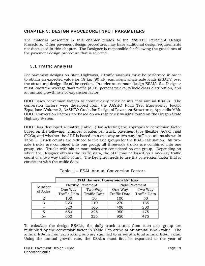
5.1 Traffic Analysis For pavement designs on State Highways, a traffic analysis must be performed in order to obtain an expected value for 18 kip (80 kN) equivalent single axle loads (ESAL’s) over the structural design life of the section. In order to estimate design ESAL’s the Designer must know the average daily traffic (ADT), percent trucks, vehicle class distribution, and an annual growth rate or expansion factor. ODOT uses conversion factors to convert daily truck counts into annual ESAL’s. The conversion factors were developed from the AASHO Road Test Equivalency Factor Equations (Volume 2, AASHTO Guide for Design of Pavement Structures, Appendix MM). ODOT Conversion Factors are based on average truck weights found on the Oregon State Highway System. ODOT has developed a matrix (Table 1) for selecting the appropriate conversion factor based on the following: number of axles per truck, pavement type (flexible (AC) or rigid (PCC)), and whether the ADT is based on a one-way or two-way traffic count, as shown in Table 1. Truck counts are reduced to five axle groups for the ESAL calculation. All two-axle trucks are combined into one group; all three-axle trucks are combined into one group, etc. Trucks with six or more axles are considered as one group. Depending on where the Designer obtains the traffic data, the ADT may be based on a one-way traffic count or a two-way traffic count. The Designer needs to use the conversion factor that is consistent with the traffic data.
Table 1 – ESAL Annual Conversion Factors
ESAL Annual Conversion Factors Flexible Pavement Rigid Pavement Number
of Axles One Way Traffic Data
Two Way Traffic Data
One Way Traffic Data
Two Way Traffic Data
2 100 50 100 50 3 220 110 270 135 4 320 160 400 200 5 650 325 950 475 6+ 650 325 950 475
To calculate the design ESAL’s, the daily truck counts from each axle group are multiplied by the conversion factor in Table 1 to arrive at an annual ESAL value. The annual ESAL’s from each axle group are summed to arrive at a total annual ESAL value. Using the annual growth rate, the ESAL’s must first be expanded to the year of

Page 20 ODOT Pavement Design Guide December 2007
construction and then forecasted to the end of the design life. The design ESAL’s are simply the sum of the annual ESAL’s through the design life, starting with the year following construction. A spreadsheet can easily be developed to expedite calculations. Part 2, Section 2.1.2 of the 1993 AASHTO Guide for Design of Pavement Structures provides guidance on the percentage of total directional ESAL’s to assign to the design lane on multi-lane highways. A detailed discussion on ESAL calculations is provided in Appendix D of the 1993 AASHTO Guide for Design of Pavement Structures. The ODOT method of traffic conversion discussed above was developed specifically for Oregon truck traffic. An example ESAL calculation using the ODOT Conversion Factors is provided in Appendix I.
5.2 Subgrade Resilient Modulus (MR) An important factor in many pavement design methods is the resilient modulus (MR) of the subgrade soil. A discussion on roadbed soil can be found in Part 1, Section 1.5 of the 1993 AASHTO Guide for Design of Pavement Structures. Selection of a value for subgrade MR is a critical step in the AASHTO Pavement Design Procedure. The Designer must be familiar enough with the project roadway design to understand if the subgrade will be in “cut or fill” (native soil versus embankment--on-site or imported) and the types of soil material (granular or fine-grained). Back-calculation is the standard method of determining the subgrade MR for pavement rehabilitation projects. Back-calculation can also be used for widening or minor realignment of highways. This procedure requires knowledge of the existing pavement structure and the use of a Falling Weight Deflectometer (Refer to Chapter 4: Data Collection for FWD testing requirements). For new work sections where back-calculated subgrade MR values are not attainable, lab determined values of resilient modulus testing of field soil samples can be used. Another available method is to perform on-site Dynamic Cone Penetrometer (DCP) testing and apply an appropriate correlation (contact ODOT Pavement Services for acceptable correlation equations). For the pavement design of minor roads off the State Highway System, classification of the soil (AASHTO or USCS) or experience/engineering judgment can be used as the basis for selecting a reasonable subgrade MR value. Due to the sensitivity of most pavement design procedures to subgrade modulus, it is very important that the modulus be calculated or tested with procedures that are consistent with the design procedure that is being used. Historical records, experience, and sound engineering judgment are valuable tools to assist in arriving at a final design MR. Caution must be used for any MR values found to be greater than 8,000 psi (55 MPa) for use in the AASHTO design procedure as this value represents a strong subgrade, which is not commonly encountered in Oregon. The soil at the AASHO Road Test Site was A-6 silty clay with a MR of 3,000 psi (20.7 MPa). The AASHTO flexible pavement design equation was developed using the MR value from the AASHO Road Test Site. MR values back-calculated from non-destructive testing data were found to be three or more times the value determined from lab tests and therefore must be multiplied by an adjustment factor (typically 0.33 for AASHTO

ODOT Pavement Design Guide Page 21 December 2007
Pavement Designs for standard flexible pavements of AC over aggregate base) to make them consistent with the AASHTO design equation. This procedure is explained in detail in Part 3, Section 5.3.4 of the 1993 AASHTO Guide for Design of Pavement Structures. The use of adjustment factors must be in accordance with the pavement design procedure used. For existing pavements with PCC pavement or cement treated bases (CTB), the adjustment factor is 0.25. Documentation must be provided showing the procedure used in determining the design subgrade MR. Included in the documentation must be any lab test reports, FWD data, and any other relevant information, and a summary providing support for the subgrade MR used in the pavement design. When a design subgrade MR value of 8,000 psi or greater is used, then specific site data is required. Specific site data shall be either laboratory MR testing, back-calculated MR from FWD data, or Dynamic Cone Penetrometer correlation (contact ODOT Pavement Services for acceptable correlation equations). Refer to Chapter 12: Deliverables for specific requirements.
5.3 Typical AASHTO Design Inputs
5.3.1 RELIABILITY The level of reliability for the pavement design must be selected in accordance with the pavement design procedure used. Table 2 shows the reliability levels to be used in pavement designs for ODOT projects designed using the 1993 AASHTO Guide. Deviations from the table must be approved in writing by the ODOT Pavement Design Engineer.
Table 2 – Reliability Levels by Functional Class
Reliability Levels Functional Class Urban Rural
Interstate 90 90 Principal Arterial 90 85 Major Collector 85 85 Minor Collector 85 80 Local 75 75 Interstate Detour (<1 year) 75 70 Interstate Detour (>1 year) 75 75 Other detour (<1 year) 60 60 Other detour (>1 year) 65 65
5.3.2 INITIAL AND TERMINAL SERVICEABILITY Part 2, Section 2.2.1 of the 1993 AASHTO Guide for Design of Pavement Structures provides a discussion on serviceability. Typical values for initial serviceability are 4.5 for rigid pavement and 4.2 for flexible pavement. For terminal serviceability, AASHTO recommends 2.0 – 2.5 for low volume roads (<3,000 ADT), 2.5 – 3.0 for medium volumes (3,000 – 10,000 ADT) and 3.0 – 3.5 for high volumes (>10,000 ADT). ODOT pavement

Page 22 ODOT Pavement Design Guide December 2007
designs usually use a terminal serviceability value of 2.5; detour or diversion pavement designs for non-Interstate roads can be designed to a value of 2.0. Different values can be used if the Designer provides adequate justification.
5.3.3 OVERALL STANDARD DEVIATION Overall standard deviation is a design input for the AASHTO procedure that takes into account uncertainty in traffic estimation and varying construction materials and conditions. AASHTO recommended values are included in Part 1, Section 4.3 of the 1993 AASHTO Guide for Design of Pavement Structures. ODOT pavement designs shall use an overall standard deviation value of 0.49 for flexible pavements and 0.39 for rigid pavements.
5.4 Layer Coefficients for AASHTO Design Procedure Table 3 is a summary of layer coefficients for use in the AASHTO Design Procedure that Designers should use for analyzing and/or designing pavement structures. Other layer coefficients may be used at the Designer’s discretion if they are justified based on an engineering assessment of the material. A discussion on AASHTO layer coefficients can be found in the 1993 AASHTO Guide for Design of Pavement Structures, Part 2, Section 2.3.5.
Table 3 – Layer Coefficient by Material Type
Material
Layer Coefficient (per 1 inch (25 mm) of thickness)
New Asphalt Concrete 0.42 New Aggregate Base 0.10 New Asphalt Treated Permeable Base (ATPB) 0.24 New Aggregate Subbase 0.08
5.5 Drainage Coefficient Adequate drainage is essential for any pavement design to succeed long-term. Drainage issues can impact both the subgrade and aggregate base materials. The AASHTO pavement design method allows for a modification of the aggregate base or subbase layers due to drainage characteristics. The drainage coefficient (mi) varies based on the quality of drainage (Excellent to Poor) and the percent time the structure is exposed to moisture levels approaching saturation. ODOT has adopted the position that the layer coefficients for new aggregate base or subbase produced under ODOT specifications already include modification for field performance due to moisture conditions. Therefore, a drainage coefficient of 1.0 will normally be used for design purposes. The use of any other drainage coefficient will require written approval (e-mail acceptable) by the ODOT Pavement Design Engineer.

ODOT Pavement Design Guide Page 23 December 2007
CHAPTER 6: NEW WORK AND RECONSTRUCTION DESIGN New work is defined as the construction of new pavement. New work includes widening of existing roads and construction of new alignments. The reconstruction of roadways on existing alignments is considered pavement rehabilitation. Although they have different definitions, the design and analysis for new work and reconstruction sections are the same and are outlined in the following sections.
6.1 Asphalt Concrete Pavement Design Requirements
6.1.1 MINIMUM DESIGN LIFE The minimum structural design life for new AC pavements is 20 years. There are no design life exceptions for new work pavement designs. Minimum structural design life criteria for new work designs at bridge approaches is 30 years, and is further discussed in Chapter 8.
6.1.2 MINIMUM AC THICKNESS
6.1.2.1 Structural Requirements AC thickness must be based on a layered analysis approach to determine the minimum thickness of AC required above the base layer for the design ESAL’s. The purpose of this analysis is to determine the minimum thickness of AC required to resist structural deterioration (fatigue cracking) of the asphalt layer. This procedure is explained in Part 2, Section 3.1.5 of the 1993 AASHTO Guide for Design of Pavement Structures. Also note the thickness of the AC layers should be rounded up to the nearest ½ inch (15 mm). For example: ODOT assumes an aggregate base modulus of 20,000 psi (138 MPa). Using the assumed base modulus as the input for subgrade MR (all other AASHTO design inputs remaining the same), the calculated SN is the SN required above the base layer. If the required SN is 2.1, a minimum AC thickness of 5.0 inches (125 mm) is required above the base layer (2.1/0.42). If a design procedure other than AASHTO is used, the minimum AC thickness must be determined in accordance with the design procedure. For high volume applications (>50 million ESALs), ODOT research and experience indicates that a practical maximum thickness of quality new HMAC (4 to 7% in-place air voids) is 10-13 inches based on fatigue resistance at the base of the AC layers. HMAC thickness greater than 12 inches should be checked for fatigue resistance based on limiting strain criteria at the bottom of the HMAC. A mechanistic pavement design may be required to determine a cost-effective pavement design. Contact ODOT Pavement Services for additional information.

Page 24 ODOT Pavement Design Guide December 2007
For projects with greater than 80 million design-lane ESALs or 30 inches total AC and aggregate base depth (excluding subgrade stabilization), contact the ODOT Pavement Design Engineer for appropriate design procedures.
6.1.2.2 Shoulders For new work or reconstruction where shoulders are built at the same time as travel lanes, shoulders will be designed to the same asphalt thickness and materials as the travel lane. Where shoulders are reconstructed separate from the travel lane, refer to the following section Roadway Widening.
6.1.3 ROADWAY WIDENING It is common practice to use existing shoulder sections to widen the travel lanes on roadways. This is acceptable if the Designer can show that the shoulder section has the structural capacity to carry the expected traffic loads (Refer to Chapter 4: Data Collection for testing requirements). In addition, a check must be made to determine whether the existing AC thickness is sufficient to resist fatigue cracking (described in Section 6.1.2). If the shoulder is structurally inadequate, it must be reconstructed or rehabilitated sufficiently to carry the anticipated design traffic. When widening a roadway, the Designer must provide continuity with the adjacent pavement section. Although it is preferable to match the adjacent pavement structure, there will be projects where that is not economically feasible. At a minimum, the design must use compatible materials and provide for adequate drainage from underneath the existing pavement. This may require constructing the top of subgrade for the widening at the same elevation as the existing subgrade, or providing an underdrain at the edge of the existing pavement that outlets beyond the new pavement structure. In addition to the afore mentioned drainage concerns, interstate highway shoulders present a unique design situation. Widening of just the shoulder may be required to provide a paved surface to meet updated safety standards. Many sections of interstate highway shoulders were originally designed to a minimum depth of 4 inches, and now need reconstruction to meet staging needs for travel lane repairs or bridge replacements. The Designer should consider the staging needs of the current or upcoming projects to provide adequate asphalt pavement depth and aggregate base structure. As a practical minimum, interstate shoulders should provide depths of at least 6 inches HMAC and 12 inches aggregate base, placed according to specifications 00745 and 00641 respectively.
6.1.4 JOINT LOCATION Construction joints in a pavement-wearing surface must not be placed in a wheelpath. In addition, for widening projects, the saw-cut edge of the existing pavement should be at a stripe or mid-lane (between the wheelpaths). Construction joints in wheelpaths have been observed to have a harmful effect on long-term pavement performance. Differential movement across the joint, material segregation and compaction problems contribute to the increased rate of pavement deterioration under traffic loading when construction joints are placed in a wheelpath. In urban areas where the wearing surface must be tapered to maintain curb exposure, the construction joint is sometimes forced into, or
ODOT Pavement Design Guide Page 25 December 2007
near, the wheelpath. This is considered acceptable when unavoidable due to geometric constraints.
6.2 Portland Cement Concrete Pavement Design Requirements This section covers information related to the construction of new PCC pavements and the widening of existing PCC pavements. For a description of the PCC pavement types typically used in Oregon, refer to Chapter 10. The rehabilitation of existing concrete pavements is discussed in Chapter 7. For pavement design using the AASHTO Guide 1993, the Designer should also refer to the Supplement to the AASHTO Guide for Design of Pavement Structures, Part II, Rigid Pavement Design & Rigid Pavement Joint Design, 1998. The use of new (jointed or continuously reinforced) concrete pavement must be approved in writing (e-mail acceptable) by the ODOT Pavement Design Engineer.
6.2.1 MINIMUM DESIGN LIFE The minimum design life for Portland Cement Concrete Pavement is 30 years. This minimum life is for all types of PCC – jointed and continuously reinforced pavements.
6.2.2 MINIMUM PCC THICKNESS The minimum thickness for PCC on state highways is 8 inches (200 mm). If PCC is being used for bus stop pads or other heavy truck stop and start areas, a thicker panel may be needed even if the traffic calculations indicate that 8 inches (200 mm) is sufficient. Typically, the thickness for PCC is rounded to the nearest 1 inch (25 mm), but consideration may be given to rounding to the nearest ½ inch (15 mm) if the project is large enough to use controlled grade slip form pavers.
6.2.3 ROADWAY WIDENING When widening next to existing PCC pavement, PCC shall be considered for the new widening. The new PCC should match the existing PCC in thickness and contraction joint location (if jointed). The new PCC must be tied to the existing PCC.
6.2.4 JOINT LOCATION AND SPACING When constructing an all new section of PCC, the joints shall be placed per the standard specifications and standard drawings. When widening an existing PCC pavement, longitudinal joints shall be placed at an edge line (skip stripe, fog stripe, etc) or mid-travel lane. This may require cutting the existing PCC to get the correct placement. New transverse contraction/expansion joints shall match with the existing joints. Proper joint design is a key factor in the performance of jointed plain concrete pavement (JPCP) and jointed reinforced concrete pavement (JRCP). For JPCP, ODOT has recently adopted a spacing of 15 feet rather than the repeating pattern as shown in Standard Drawing RD600 (1 May 07-31 Oct 07). A joint spacing that is too long will result in
Page 26 ODOT Pavement Design Guide December 2007
intermediate transverse cracks in the slab. These intermediate cracks can cause pumping, faulting and additional cracking that eventually lead to costly repair. The joint spacing in JRCP is typically longer than those used in JPCP. This is due to the presence of longitudinal steel reinforcement. Although intermediate transverse cracks may develop, the longitudinal steel provides for additional load transfer beyond the basic aggregate interlock and keeps the cracks tight. The joint spacing provided in ODOT Standard Drawing RD600 should be verified by the designer for each specific reinforced concrete pavement design. Special consideration shall be given to non-standard situations. These situations may include: intersections, taper sections, bus stops, and urban areas with obstacles such as manholes, inlets, etc. These special areas require a joint layout detail in the plans and may require additional drawings and modifications to the specifications. There are no regularly spaced transverse contraction joints to design for in continuously reinforced concrete pavement (CRCP). However, the designer does need to design for the transverse crack spacing. Transverse cracks shall be designed for a spacing of 3.5 to 8 feet (1.1 to 2.4 m). The crack spacing and width are controlled by the percentage of longitudinal reinforcing steel in the pavement. Controlling terminal expansion in CRCP is very important. The design principle is to allow for expansion and contraction to occur and minimize damage to the pavement. There are two basic types of terminal expansion joints used in CRCP. The lug system is used to restrain free end movement, while the wide flange beam system is designed to accommodate the free end movement and minimize damage. Currently ODOT uses a wide flange beam system for terminal expansion joints as the standard design. Several issues have arisen concerning the long-term performance of the wide flange beam in Oregon, including snow plow damage, fracture and displacement of the top flange, and difficulties in maintenance and repair. The choice of using a wide flange beam or a lug system should be addressed in the pavement memo/report. A terminal end joint system is required in CRCP at all bridge approaches and at the ends of the CRC pavement. The wide flange beam terminal expansion joint at a bridge approach shall be constructed per Standard Drawing RD600 and Standard Detail DET1605.
6.2.5 DESIGN DETAILS This section covers specific design related details. Chapter 11 of this guide discusses the specifications and Standard Drawings/Details required for new PCC pavements.
6.2.5.1 Load Transfer Load transfer refers to the ability of a concrete pavement to transfer or distribute a load across discontinuities such as joints or cracks. This is typically accomplished through aggregate interlock, dowel bars, or steel reinforcement. Without good load transfer, PCC pavements will exhibit distresses such as faulting, pumping, and corner breaks. For jointed concrete pavement on state highways, dowel bars are required. The dowel bar diameter should be equal to 1-1/4 inches (31 mm) or the slab thickness (inch or mm) multiplied by ⅛, whichever is greater. The dowel bar length shall be a minimum of 18

ODOT Pavement Design Guide Page 27 December 2007
inches (450 mm) or 2 times the slab thickness (ACPA, Concrete Pavement for Trucking Facilities). Dowel bars are only used with CRCP in the expansion joints at bridges. There are no contraction joints in CRCP that require dowel bars as in JPCP or JRCP. However it is important to maintain load transfer at construction joints and transverse cracks. This is accomplished with the longitudinal reinforcing steel.
6.2.5.2 Base/Subbase Materials Good base materials under a PCC pavement are an important component of long term performance. Although the rigid nature of PCC allows it to bridge minor imperfections in the underlying material, good uniform support is essential. The base layer may:
• Assist in controlling shrinking and swelling of soils • Aid in controlling frost heave • Help prevent pumping of fine grained soils • Act as a working platform for pavement construction
(Construction and Rehabilitation of Concrete Pavements, A Training Manual, FHWA, Contract No. DTFH-61-81-C-00051, pg VI-20) Base materials may take several forms including: granular materials, asphalt or cement treated materials, or lean concrete base. ODOT has at one time or another used all of these types of base materials under PCC pavements. Based on information presented at the Concrete Pavement Design- 2000 and Beyond Workshop, August 2000 in Breckenridge Colorado, and ODOT experience, stabilized bases provide better performance than un-treated base materials. Stabilized bases provide better uniform support and are less susceptible to pumping and erosion beneath the PCC pavement. The type of base to be used depends on the project. Small projects replacing or widening existing PCC Pavement should consider matching existing base types. Large projects shall use a stabilized base. Currently ODOT uses an HMAC stabilized base.
6.2.5.3 Subdrainage Subdrainage is an important factor in the performance of all types of PCC pavement. Water infiltration from the surface or the subgrade contributes to joint faulting and pumping of the subgrade fines. As this process progresses, a loss of support occurs which leads to more serious distresses such as faulting, corner cracks/breaks, and punchouts. Subdrainage, in conjunction with other design features can be used to help prevent the problems noted above. Providing for subdrainage is good practice and should be considered for all PCC pavement types. Subdrainage could include the use of longitudinal edge drains or an open graded HMAC base course with drains. The longitudinal edge drains provide for drainage of the subgrade, while the open graded HMAC is used to drain moisture from the base course beneath the PCC pavement. Standard Drawing RD312 is used for both the longitudinal edge drains and the open graded HMAC base course drains. However,

Page 28 ODOT Pavement Design Guide December 2007
the drawing is very general and should be supplemented with a project specific detail for use with either of the subdrainage methods mentioned above. When developing the detail for an open graded HMAC base course, consideration should be given to not pave directly on the plastic pipe material. The high temperature of the HMAC during placement has a tendency to melt the drain pipe. There may be other options for providing subdrainage that are not addressed above for the specific circumstances of the project. It is the Designer’s responsibility to provide an appropriate detail for the subdrainage to be included in the project plans. For more information related to subdrainage drawings and details, please contact the ODOT Pavement Services Unit.
6.2.5.4 Shoulder The AASHTO design method considers the lane edge support condition as a design element. An edge support adjustment factor is as follows:
E = edge support adjustment factor (1.00 for original AASHO Road Test) = 1.00 for conventional 12 ft (3.66 m) wide traffic lane = 0.94 for conventional 12 ft (3.66 m) wide traffic lane plus tied concrete shoulder = 0.92 for 2 ft (0.6 m) widened slab with conventional 12 ft wide striped lane
ODOT has adopted the use of a 14 foot wide slab adjacent to the shoulder, striped as a 12 foot lane. For jointed plain concrete pavement, the adjacent shoulder may be JPCP or HMAC. For continuously reinforced concrete pavement, the adjacent shoulder shall be HMAC, designed according to Section 6.1. Variance from the 14 foot width will require written approval (e-mail acceptable) from the ODOT Pavement Design Engineer.
6.3 Subgrade Improvement Subgrade soil can be improved in excavation areas to increase the workability and structural value of undesirable native materials. Subgrade improvement can be achieved by replacing the soil with a more desirable material (subgrade stabilization) or by treating the soil with an admixture such as lime or cement. Subgrade improvement shall be considered and undertaken when soft or unstable soils are anticipated, the soil is saturated, or the construction time-line does not allow for drying a wet subgrade. If an admixture is to be used for the subgrade improvement, lab testing is required to determine the proper amount of admixture to achieve the desired soil properties. The ODOT Pavement Design Engineer must approve in writing (email acceptable) alternative methods (not listed above) of subgrade improvement prior to final design recommendation. There are separate specifications (Refer to Chapter 11: Specifications) for each of the subgrade improvement methods described above.

ODOT Pavement Design Guide Page 29 December 2007
6.4 Design Alternatives Several design alternates must be considered for new construction. Alternates may include, but are not limited to, variations in AC/agg base thickness, full depth AC, and PCC over base. Cement Treated Base is not an acceptable structural component for pavements on State Highways in Oregon. However, cement stabilization for subgrade improvement or for preparing a construction platform (cement modified soil) is an acceptable practice. Other design section alternatives (not discussed in this guide) must be approved in writing (email acceptable) by the ODOT Pavement Design Engineer prior to submission of the design. A discussion of each alternate considered and a Life Cycle Cost Analysis (LCCA) must be included in the design report (if applicable). For more information on LCCA, refer to Chapter 9: Life Cycle Cost Analysis. For minor widening of existing roads, development of design alternatives is not required.
6.5 Special Considerations
6.5.1 BRIDGE APPROACHES Bridge approaches require special consideration for new work pavement designs. Refer to Chapter 8 for a discussion and design guidelines for bridge approaches.
6.5.2 FROST DESIGN Frost heave and thaw weakening must be considered for projects where the following three elements exist: frost susceptible soil, freezing temperatures / high freezing index, and water. If any one of the three elements is not present, then frost heave and thaw weakening will not exist. In Oregon, frost heave and thaw weakening are primarily concerns east of the Cascade Mountain Range. Where there is a potential for frost problems, the design must eliminate at least one of the three elements. Typically making the total depth of the pavement structure greater than the frost depth is how the frost problems are eliminated. A positive drainage that eliminates the water in the soil may be considered, but usually is too expensive compared to removing one of the other two elements. The frost susceptible soil may be removed or treated to below the depth of frost penetration to change its properties to be non-frost susceptible. Treatment can include mixing cement or lime at low percentages. Frost depth can be determined with test pits in the area of a project, or through calculations utilizing the freezing index for the area (see CRREL procedure). More information on frost design considerations can be gathered from Cold Regions Research and Engineering Laboratory (CRREL), , and the 1993 AASHTO Guide for Design of Pavement Structures, Part 1, Section 1.7.
6.5.3 VERTICAL CLEARANCE AT BRIDGE UNDERPASSES The minimum vertical clearance standard under bridges on the interstate is currently 17’-6” for new work areas (includes 0’-6” for future AC overlays). A standard may apply on other highways depending on local trucking requirements. This issue relates to new

Page 30 ODOT Pavement Design Guide December 2007
mobility standards ODOT is working to achieve. In some instances, to increase the existing vertical clearance at a bridge, the alternative may be to lower the roadway gaining some or all of the necessary vertical clearance, or the bridge may be a candidate for raising or replacement. When rebuilding a pavement under any structure to gain minimum vertical clearance requirements and there is insufficient clearance for future overlays, the pavement design life shall be 30 years. The design life applies regardless of the type of project (preservation, modernization, bridge) the work is being completed under. Structures with vertical clearance issues are to be identified by the Project Team.

ODOT Pavement Design Guide Page 31 December 2007
CHAPTER 7: REHABILITATION OF EXISTING PAVEMENT STRUCTURES The primary function of a pavement rehabilitation is to restore or extend the serviceability of the pavement for a given design life. This includes structural improvements where required to provide the necessary structural capacity for the anticipated traffic loading. This may also include non-structural improvements in situations where additional structural capacity is not required. Typically, structural improvements can be achieved in two ways: Additional depth of materials, which increase the structural capacity of the section, or the replacement of deficient existing materials with new materials. Under specific circumstances, the rehabilitation of deficient existing materials may require complete reconstruction of the roadway. A key element in the rehabilitation of an existing pavement is the mitigation of deficiencies in the existing pavement that will impact the survivability of the pavement rehabilitation for the required design life. This includes, but is not limited to, conditions such as cracking, raveling, stripping, flushing, or potholes. Vital to the performance of pavement in certain parts of the state is the adequate design for frost heave and thaw weakening. For more on this, please reference Section 6.5.2, Frost Design. It is the Designer’s responsibility to establish the most effective form of rehabilitation while minimizing project costs.
7.1 Design Life The minimum structural pavement design life required by ODOT is 15 years for the preservation of an existing pavement structure (this is the basis for ODOT’s present preservation strategy), in contrast to a reconstruction section where the design life of a new pavement is 20 years for AC and 30 years for PCC. However, under specific circumstances, a reduced design life for preservation may be justifiable. If a reduced design life is considered, certain requirements must be met. A reduced design life for rehabilitation may be considered if a Life Cycle Cost Analysis (LCCA) indicates that a significant cost savings could be realized by providing something less than the minimum design life. An example might be an urban section where a relatively thick overlay is required to restore structural capacity. If grade constraints such as curb exposure, right of way, or cross slope make a thick overlay impractical, complete reconstruction often becomes the most viable full design life alternative. However, repeated thin surface treatments such as a thin inlay at shorter time intervals may be more cost effective than the complete reconstruction of the pavement. A reduced design life may also be considered acceptable if for a given section of highway, there is in place in the State Transportation Improvement Plan (STIP) another project that will provide for future rehabilitation, reconstruction, or replacement of the pavement

Page 32 ODOT Pavement Design Guide December 2007
section. An example would be a section of highway that was scheduled for replacement under a future project, but needs some form of immediate rehabilitation to mitigate significant safety concerns for the motoring public. Pavement designs with a design life of less than eight years require a design life exception. In these instances, written documentation providing a description of and justification for the exception must be included in the deliverables (see Chapter 12). The primary form of justification shall be a life cycle cost analysis, which clearly demonstrates the cost effectiveness of the exception. The ODOT Pavement Design Engineer must review all requests for pavement design lives of less than the minimum 15 years. The Area Manager and the State Roadway Engineer must approve the design life exception in writing for design lives less than 8 years. The design exception process is discussed in more detail in Chapter 13 of the ODOT Highway Design Manual. In addition, the Highway Design Manual provides the required format for the design exception request form. For additional information on the development of Life Cycle Cost Analyses, please see Chapter 9 of this guide.
7.2 Field Work One critical element in the development of a pavement design is the collection of on-site test data, material samples, and a documented evaluation of the condition of the existing pavement. To obtain this information, the Designer shall follow the requirements in Chapter 4 of this guide.
7.3 Bridge Approaches Pavement designs for rehabilitation at bridge approaches require special consideration. Please refer to Chapter 8 for a discussion on bridge approaches.
7.4 Vertical Clearance at Bridge Underpasses On both the interstate and state highways, the vertical clearance under structures requires special treatment. Depending on the existing vertical clearance, an overlay may not be acceptable due to a decrease in vertical clearance. If the existing vertical clearance is between 16’-0” and 17’-6”, the final clearance requirements should be determined through the Project Team. If the existing clearance is to be maintained, this situation may require additional fieldwork to determine if an inlay is acceptable. If the existing vertical clearance is below Freight Mobility standards, consideration will be given to rebuilding the roadway or raising the structure. Reconstruction of a pavement under a bridge is discussed in Section 6.5.3. Again, actual bridge clearance requirements should be determined through the Project Team.

ODOT Pavement Design Guide Page 33 December 2007
7.5 Functional and Structural Pavement Conditions Several of the field investigative methods discussed in this guide provide a method to quantify structural-related pavement distress, and ultimately lead to a rehabilitation technique such as AC inlay and/or overlay. In some cases, the structural analysis may indicate no inlay/overlay is necessary. Although no structural repair may be required, an inlay/overlay may still be appropriate to mitigate other functional pavement distress such as raveling, rutting, low skid resistance, etc. In summary, structural pavement condition refers to the load (traffic) carrying capacity; functional pavement condition refers to the ride character or quality of the roadway surface. Pavement distress impacting one or both of these functions may necessitate the use of an inlay and/or overlay repair.
7.5.1 EVALUATION OF FUNCTIONAL CONDITION The process of determining the functional condition of a pavement begins with a data evaluation, as demonstrated in the AASHTO Guide (1993), Section III, subsection 2.3.2. This evaluation can often be performed as a subjective visual observation of the pavement surface for conditions such as roughness, potential skid resistance issues, and rutting severity. If questions still exist as to the comparative rating, test data may exist or be obtained for indicators such as IRI, skid test, and laser-measured rut depth. Some functional condition information is collected by ODOT Pavement Management staff for the production of various condition reports. Data such as IRI, rut depth measure, and possibly skid test value may exist from previous pavement condition assessments. Contact ODOT Pavement Services staff for assistance in obtaining available functional condition data.
7.5.2 EVALUATION OF STRUCTURAL CONDITION
7.5.2.1 Non-Destructive Testing ODOT has adopted the use of non-destructive testing as the method to quantify existing pavement structural capacity. The primary method is through FWD testing (see Chapter 4). The deflection data provides differing analysis results depending on pavement type, as shown in Table 4. The deflection data is often times useful to quantify the variability of pavement conditions through the project limits, such as changes in subgrade Mr and average deflection value. This allows the Designer to determine various uniform sections for analysis. These uniform sections may later be combined into similar design units. Deflection analysis may also be used to back-calculate the individual layer moduli for use in mechanistic-empirical design methods.

Page 34 ODOT Pavement Design Guide December 2007
Table 4 Deflection Data Analysis Results by Pavement Type
PCC (rigid) AC (flexible)
• Examine load transfer efficiency at joints and cracks
• Estimate subgrade soil resilient modulus
• Estimate the effective modulus of subgrade reaction (effective k-value)
• Provide a direct estimate of the effective Structural Number (SN) for the pavement
• Estimate the modulus of elasticity for the concrete (strength)
• Back-calculation of modulus values for asphalt and aggregate layers
7.5.2.2 PCC Joint Load Transfer
Joint load transfer is the efficiency of the slabs to dampen the deflections due to wheel loads across the joint by transferring the load. Load transfer can be the result of aggregate interlock, foundation support, dowel bar shear transfer, or a combination of mechanisms (NCHRP Project 1-21, 1985). Load transfer is calculated as:
B×100×dldu
=%LT ][ )(
du = deflection of unloaded slab dl = deflection of loaded slab B = Slab bending correction factor
120
ddB =
d0 = deflection under load cell d12 = deflection at 12 in (300 mm) from load cell For further information on load transfer, refer to Part III, Section 5.6.5 of the 1993 AASHTO Guide for Design of Pavement Structures. The results of the load transfer calculations should be used to determine the average load transfer for the section tested.
7.5.2.3 Remaining Life The remaining life concept of structural condition involves determining the percentage of remaining life based on the amount of traffic the pavement has carried to date along with the total amount of traffic that the pavement could carry to “failure.” Determining the actual amount of traffic the pavement has carried to date may be difficult due to uncertainties in traffic growth over the years, changes in number of lanes, previous rehabilitation, etc. Often the best one can do is make an estimate backwards from current data to date of construction. The remaining life approach is further discussed in AASHTO Guide (1993) Section III, subsection 5.3.3.

ODOT Pavement Design Guide Page 35 December 2007
7.6 Rehabilitation Design Alternatives On many projects there may be more than one feasible alternative for the rehabilitation of the existing pavement. Alternatives may include, differing material types, or variations in the proportional depths of the different materials involved. An alternative may be based on a functional condition issue such as severe rutting or high roughness. All viable alternatives should be considered. Some may be eliminated quite easily based on issues such as cost, ease of construction, risk of premature failure, staging, right of way, etc. Others may require detailed study and life cycle cost analyses to determine the preferred alternative. The preferred alternative should be considered the one that meets the desired requirements for pavement survivability and design life at both the lowest monetary cost and least acceptable impact to the traveling public.
7.7 AC Pavement Rehabilitation
7.7.1 STRUCTURAL REQUIREMENTS FOR AC OVERLAY Essentially, there are two structural requirements with which a pavement section must meet or exceed: total structural capacity, and fatigue life of the pavement components themselves. All components of the design section (including the underlying native subgrade) must provide a combined structural capacity capable of supporting the anticipated traffic loading in accordance with an acceptable design procedure (see Chapter 2 of this guide). In addition, each pavement layer must have a total depth that is sufficient to support the anticipated traffic loading without suffering premature fatigue failure. To accomplish this it is necessary to determine the minimum asphalt concrete pavement depth required over the underlying layer(s). ODOT pavement designers will typically accomplish this by determining the Structural Number (SN) required for the asphalt concrete based on the anticipated resilient modulus of the structural layer immediately beneath the asphalt concrete (Refer to Section 6.1.2). The process is outlined in the 1993 AASHTO Guide for Design of Pavement Structures under Part II, Section 3.1.5. The primary method for determining the thickness of AC overlays is by the AASHTO Guide (1993).
7.7.2 PRE-OVERLAY REPAIRS Prior to the placement of an overlay or inlay, an evaluation of the condition of the existing pavement should be conducted that includes the type, quantity, and severity of pavement distress that is present. The pavement design must then provide for any pre-overlay repairs that may be deemed necessary. The pre-overlay repairs may include (but are not limited to):

Page 36 ODOT Pavement Design Guide December 2007
• Localized areas of thin grind and inlay to repair non-structural conditions such as
surface cracking, delamination, shoving, etc. • Localized areas of structural failure that require surfacing stabilization, this is
covered in more detail later in this chapter • Leveling with HMAC of wheeltrack ruts with depths greater than ½ inch (13 mm) • HMAC leveling to restore correct cross section or profile • Removal of existing open graded wearing course (see Section 10.1.1)
7.7.2.1 Reflective Crack Control
In the development of a pavement design recommendation, control of reflective cracking from the underlying existing pavement is a critical element on many projects. The Designer must evaluate the type of cracking that is present as well as the extent and the severity of the cracks. If reflective cracking is found to be a potential threat to the survivability of an overlay or inlay, efforts to mitigate this cracking shall be incorporated into the design. A partial list of mitigation techniques is provided below. When considering a technique for controlling reflective cracking, the Designer needs to consider the reliability of the proposed technique. Other factors that need to be considered are the cost to the project, impact on staging and/or right of way, and the potential for grade constraints. Perhaps the most common technique for control of reflective cracking is the removal by cold planing of all or part of the cracked surface prior to placement of an inlay or overlay. This approach may be effective if the cracking does not extend too deep into the existing pavement and if minimal increase in total structure is required. Another approach to controlling reflective cracking is increasing the depth of the Hot Mix Asphalt Concrete (HMAC) overlay. The more new pavement that is placed over a crack, the longer it will take that crack to reflect through to the surface. This approach is especially effective if a substantial increase in structural capacity is required anyway. It has been demonstrated that the more flexible binders found in Emulsified Asphalt Concrete (EAC) will tolerate a greater degree of flexure than HMAC, thereby helping to retard reflective cracking. This technique is acceptable in Eastern Oregon where climatic conditions allow for the proper curing of EAC. This technique is not used in Western Oregon where temperature and humidity hamper the proper curing of EAC. For more information on mix type selection please reference Chapter 10 of this guide. Often, it may not be economically feasible to implement a rehabilitation strategy that provides for long term reflective crack mitigation. Certain types of cracking such as full depth thermal cracks, shrinkage cracks in underlying cement treated base, and joint cracks in underlying jointed concrete pavement can be exceedingly difficult to mitigate on a long-term basis. Under specific conditions it may be necessary to make the decision to not attempt crack mitigation for the full design life of the new pavement. In such a case, the Designer must provide adequate explanation in the deliverables (Chapter 12) as to why such a decision was made.

ODOT Pavement Design Guide Page 37 December 2007
7.7.2.2 Cold Planing Guidelines Cold planing can be done full width across the pavement, or to a width of 2 feet (0.6 m) outside of the existing fog stripe. Typically, full width cold planing is used in limited situations, such as:
• On an existing open graded wearing course where the cross section slopes toward the travel lane
• Narrow shoulders • It is required for traffic control • Potential grade constraints
Cold plane pavement removal 2 feet (0.6 m) outside the existing fog stripe may be used for situations of:
• High truck traffic combined with wide shoulders • Winding roads with the likelihood of vehicles to stray outside the fog stripe • Wide shoulders, where vehicles are more likely to “hug” the fogline • Existing pavement has been inlaid and therefore consideration shall be given to
the performance of the existing joint • Overlay of the inlay is less than 4 in (100 mm) and one of the other conditions
apply • Substandard (<12 ft (3.6 m)) travel lane width causing vehicles to “shy” away from
the centerline • On the Interstate • As deemed necessary on a project by project basis
It is the Designer’s responsibility to determine if traffic can be allowed on the cold planed surface prior to placing an inlay or overlay. In making the determination, the following should be considered: thickness of existing pavement after the section has been cold planed; depth of existing delaminations or stripped pavement; depth to existing cement treated base (CTB), if present; and traffic volumes. This list is not all inclusive. This must be specifically addressed in the Pavement Design Report.
7.7.2.3 AC Pavement Repair (Surfacing Stabilization) Note: The term “Surfacing Stabilization” is currently used for specification 00332 of the 2002 edition of the Oregon Standard Specifications for Construction. This terminology is proposed to change in the 2008 version of the Specifications. The proposed change is specification 00748 Asphalt Concrete Pavement Repair. When localized areas of apparent structural failure are identified, either through testing or by visual evaluation, provision must be made in the pavement design for their repair using surfacing stabilization. The concept of surfacing stabilization provides for the repair of severely deteriorated pavement through the removal and replacement of the

Page 38 ODOT Pavement Design Guide December 2007
existing pavement, the underlying base material, and soft or unstable subgrade located beneath the base. It is the Designer’s responsibility to determine the locations of such repairs, identifying them by length, width, milepoint or station, and the lane in which they occur. The preferred time to locate surfacing stabilization sites is prior to (but as close as possible to) Advance Plans preparation. If possible, mark the sites along the shoulder with white paint (or other semi-permanent marker such as a tack and/or lath). Typically, a width of no less than 6 ft (1.8 m) is considered for surfacing stabilization. This is half the width of a typical travel lane and is generally considered a practical minimum for constructability reasons. The Designer must also provide an estimated depth for the subbase material that will be used to replace soft or unstable subgrade. Since the exact depths of soft or unstable subgrade in each location are not always known, the specification covering surfacing stabilization allows for variation in depth of the subbase once the pavement and base have been removed and the subgrade evaluated. In some instances, removal of subgrade may not be needed at all. Provision shall be made in the pavement design stating that if upon exposure, the existing subgrade is found to be stable; the subbase portion of the surfacing stabilization recommendation may be omitted. (Note: it is ODOT standard specifications guidance to not include 00331 Subgrade Stabilization at the same locations as Surfacing Stabilization (Asphalt Concrete Pavement Repair). See Section 11.3.1 for additional discussion on specification 00331). Surfacing stabilization applies to existing flexible pavements (AC over aggregate base or CTB). The Surfacing Stabilization HMAC Detail should not include any overlay lifts included in the pavement design for the corresponding section; the design is to match existing grade. Rigid pavements (jointed or continuous PCC) require special considerations and specifications, as discussed in Section 7.8. The Pavement Design Memo/Report shall provide a specific structural section to be used for areas requiring surfacing stabilization. Refer to Chapter 11 of this guide for information related to the application of this specification. The design life for Surfacing Stabilization is usually 20 years; however, the Designer may use a design life of 15 years with adequate justification and written approval (e-mail acceptable) by the ODOT Pavement Design Engineer. One such example would be a known time period to complete reconstruction.
7.7.3 AC PAVEMENT OVER CEMENT TREATED BASE In years past, ODOT used Cement Treated Base (CTB) fairly extensively around the state. Many of these locations have now reached the point where some form of rehabilitation is required. In the evaluation of an existing pavement section with underlying CTB, great care must be taken to evaluate the integrity and condition of the CTB using a visual evaluation of the overlying pavement and cores taken through the pavement and CTB. As a freshly placed CTB cures, it will naturally develop shrinkage cracks. With time and exposure to heavy traffic loads, stress will cause the CTB to continue cracking into smaller pieces. If this process is not mitigated by reducing the stress, the CTB will eventually deteriorate to the point where it functions more as an aggregate base than as a bonded base layer.
ODOT Pavement Design Guide Page 39 December 2007
The most common method used by ODOT for rehabilitating a pavement with underlying CTB is to reduce the stresses by placing additional depth of new pavement over the CTB. This is a viable option if the underlying CTB is not severely distressed or broken. In many cases, this involves placing additional AC depth even though deflection testing indicates that little or no additional AC depth is required for structural improvement. Depending on the condition of the existing pavement, this may or may not include a grind and inlay prior to the overlay. When analyzing the rehabilitation needs of the AC layer over CTB, ODOT has adopted the practice of calculating the traffic as rigid ESALS, as discussed in AASHTO Part I, Section 1.4.1. Typically, ODOT considers 6.0 inch (150 mm) of HMAC to be the practical minimum depth over any CTB. In an urban location, or other setting where the option of increasing grade through an overlay is limited, or the CTB is severely distressed or broken, reconstruction may be the only viable option. An evaluation of an existing pavement and underlying CTB (such as back-calculation of layer moduli) may determine that a severely deteriorated CTB is no longer functioning as a bonded layer. In the subsequent analysis the pavement designer should consider the CTB to be an un-bonded layer with a layer coefficient closer to that of an aggregate base than that of a cement-treated base and develop their overlay design accordingly (use flexible ESALs conversion factors). Currently, ODOT uses very little new CTB. Where it is used is usually limited to areas where a section of new construction is being placed adjacent to an existing section which has AC over an underlying CTB. However, this may not be cost effective in a small quantity, since CTB could be very expensive to produce and place. In this scenario, ODOT designers will often use an AC over aggregate base section that minimizes the depth of the aggregate base (no less than 6.0 inches (150 mm)). This will usually result in a depth of AC that is significantly greater than the minimum required to resist fatigue. This has the advantage of reducing flexure in the new section which minimizes the difference in flexural characteristics between the two pavement sections.
7.8 PCC Rehabilitation Structural and surface deficiencies in existing PCC pavement must be corrected as described below. If the PCC has been overlaid with AC, it may not always be possible to identify locations of broken PCC pavement that need repair. If a visual evaluation of an AC over PCC pavement section suggests that the underlying PCC is cracked or broken, the Designer shall use professional engineering judgment to determine which areas warrant repairs and which do not. If the locations of the joints in the underlying PCC are identifiable, then deflection testing across the joints to determine voids and load transfer is required. It is also important to note that many older PCC pavements were constructed to widths significantly less than modern pavement sections. This often times results in a longitudinal joint between the old PCC and more recent widening that lies within or near a wheel track. In this situation, the design must address the pavement immediately on either side of the longitudinal joint as this pavement is subjected to edge loading. If the PCC pavement surface is exposed, then evaluation of the pavement condition and subsequent rehabilitation takes a slightly different technique. If the pavement surface is to remain exposed, that is, no AC overlay is to be applied; virtually all structural

Page 40 ODOT Pavement Design Guide December 2007
deficiencies in the existing PCC will need to be repaired. If an AC overlay is to be placed over the PCC, then only those distresses that will affect the structural performance of the new AC surfacing will need to be repaired prior to the overlay. However, consideration must be given to future rehabilitation of distresses left un-repaired prior to an overlay. Further deterioration of low severity cracks and breaks may be masked by the overlay and go un-noticed until a major structural problem develops. In addition, the overlay makes future repairs more difficult in terms of traffic staging and construction because the HMAC must be removed prior to making the repairs. Deflection testing across the joints to evaluate voids and load transfer is required. For more information on load transfer and void detection testing refer to chapter 7.
7.8.1 STRUCTURAL REQUIREMENTS FOR PCC PAVEMENT The structural requirements for a PCC pavement involve establishing the structural adequacy of the pavement, and comparing to future anticipated traffic loadings over the rehabilitation design life. If the pavement rehabilitation design life for both functional and structural needs can be met with just pavement repairs, then an overlay is not required. Alternately, if the pavement repairs are not sufficient to provide the required design life, or are not cost-effective in restoring functional requirements, then an HMAC overlay, or possibly reconstruction, is required. Currently ODOT does not have a design standard for PCC overlays.
7.8.2 PCC PAVEMENT REPAIRS Repairs to existing concrete pavements generally take the form of partial depth patching or full depth patching. On projects where any or all of the above concrete pavement repairs are necessary, consult the ODOT Pavement Design Unit (503-986-3000) for assistance in determining appropriate repair techniques, details, and special provisions.
7.8.2.1 Partial Depth Repairs Partial depth patching is used for spall repairs at joints or to repair voids or imperfections in a concrete surface. It is not intended to repair structural deficiencies in PCC pavements. This work consists of a partial depth saw cut around the perimeter of the affected area, removal of the existing concrete and the placement of an approved low slump PC patch material, selected from the Qualified Products List (QPL). The Designer is responsible for providing an appropriate detail for partial depth repairs to be included in the contract plans. Partial depth repairs should be limited in depth to the top third of the slab and should not come in contact with dowel bars or reinforcing steel. If dowel bars or reinforcing steel are encountered, a full depth repair is required.
7.8.2.2 Full Depth Repairs Full depth patching of PCC pavements is used to repair structural deficiencies such as corner cracks or breaks, longitudinal cracks, and punchouts. The specific details of full depth patching vary depending on the type of PCC pavement to be repaired.

ODOT Pavement Design Guide Page 41 December 2007
For jointed concrete pavements, full depth patching involves saw cutting and removing the existing distressed concrete. The patch area shall be tied to the existing PCC with tie bars, as appropriate. If the patch edge is 3 feet or less from a transverse joint, extend the patch to the existing transverse joint. If the patch edge is adjacent to or crosses a transverse joint, then a new joint shall be constructed in the same location. The new transverse joint shall be dowelled regardless of the presence of dowel bars in the existing concrete pavement. The dowel bars insure adequate load transfer across the joint. For JRCP, reinforcing steel shall be included per standard drawing RD600. Full depth repairs in jointed reinforced concrete pavement shall include a bar lap splice in the longitudinal direction to tie new reinforcing steel to the existing reinforcement. Full depth patching in CRCP is more involved. Repair areas shall be a minimum of 3 feet (900 mm) beyond the end of a longitudinal crack extending from a broken area. When repair areas have been stopped shorter than this, the risk of failure has been shown to be quite high in Oregon and in other states. Transverse edges of the repair areas shall be a minimum of 18 inches (450 mm) from a tight transverse crack. This requirement is to avoid failure at the patch edges in the form of punchouts. In addition to the full depth saw cut around the distressed area, CRCP requires an additional area to be removed on each end of the patch for splicing of the longitudinal steel reinforcement. This area is commonly referred to as the bar lap area. A partial depth saw cut, approximately 2 inches (50mm) in depth is used to avoid damaging the existing pavement reinforcement. Jackhammers and hand chipping tools are used to chip away the existing PCC to expose the steel reinforcement to which the new steel is tied. It is critical that the existing steel is not chipped or bent during the removal process. It is also important that the new reinforcing steel be included in the repair and tied properly. The longitudinal steel shall match the existing reinforcement in size and spacing. The transverse reinforcement matching the existing size shall be included in the repair at a spacing of 1 foot (0.30m) center to center. The purpose of the extra reinforcement is to keep any longitudinal cracks tight that do develop within the repair area. When making full depth repairs care shall be taken to avoid damage to the existing PCC that is to remain in place. If the remaining concrete is spalled or damaged, the patch area shall be extended to include the damaged area. Damage to the existing pavement surrounding the patch will ultimately lead to patch failure. Care should also be taken during construction to avoid damage to the existing base materials. However, provision shall also be made for replacement of base materials that are found to be damaged, deteriorated or in poor condition. Base materials should be replaced with plain concrete pavement (see Specification Section 00758.41(c)). A bond breaker must be placed between the new base and the concrete pavement. The minimum patch length (including distance from a transverse joint) in PCC pavements shall be no less than 6 feet (1.8 m). The minimum repair width is full-lane for jointed plain concrete pavement, and 6 feet (3.0 m) for reinforced pavements. The designer shall provide the appropriate details to be included in the contract plans.

Page 42 ODOT Pavement Design Guide December 2007
7.8.2.3 Other Repair or Maintenance Activities
Other rehabilitation work may include items such as joint sealing, undersealing, diamond grinding and dowel bar retrofits. Joint sealing is typically used to seal the joints to prevent water from entering into the base materials and to keep incompressibles out of the joints. Undersealing is used to fill voids or stabilize the support underneath an existing pavement subject to excessive movement. This work is normally performed on concrete pavements at joints or working cracks. Undersealing consists of drilling holes in the existing pavement and pumping grout underneath. The specifications should address the potential problem of using too much grout and lifting the pavement. This creates voids under other portions of the slab and leads to additional distress. The Designer is responsible for providing a detail showing the number and spacing of the holes and for estimating grout quantities. A detailed description on how to determine the existence of a void and determining grout quantities is provided later in this chapter. Diamond grinding can be used to remove shallow ruts or to improve the ride qualities of the PCC pavement. Ride qualities can be improved in JPCP and JRCP where minor faulting is a problem. Diamond grinding is also done in conjunction with other techniques such as patching and dowel bar retrofits. Dowel bar retrofit is a method used to restore, or provide better, load transfer across transverse joints or cracks using dowel bars. The typical indicator for dowel bar retrofit is excessive faulting (loss of load transfer) in an otherwise structurally sound pavement. To date, Oregon has not conducted any dowel bar retrofit projects. However it has been used successfully in many other states, including in the Pacific Northwest.
7.8.2.4 PCC SLAB VOID DETECTION Part 3, Section 3.5.5 of the 1993 AASHTO Guide for Design of Pavement Structures presents three methods for detecting voids under PCC pavements. The three methods are:
1. Corner Deflection Profile method – This method is based on exceeding a predefined maximum 9,000 lb (40KN) deflection under the load cell to determine the existence of a void.
2. Variable Load Corner Deflection – This method is based on using three load levels
to determine the existence of a void. This procedure was developed under NCHRP Project 1-21, 1985.
3. Void Size Estimation – This procedure identifies the existence of a void and the
approximate area. The procedure was developed under NCHRP Project 1-21, 1985.
The AASHTO Guide (1993) and NCHRP report referenced above state that a void exists if the zero load deflection is greater than or equal to 0.002 in. (0.05 mm). Based on

ODOT Pavement Design Guide Page 43 December 2007
experiences in Oregon and Washington, ODOT has found that when undersealing slabs that meet the AASHTO criteria, with a 0.002 to 0.006 in (0.05 – 0.15 mm) zero load deflection, additional problems can be created which off-set the benefits gained from undersealing. Since these voids tend to be relatively small, there is a tendency to raise the slab, creating a larger void elsewhere under the pavement. The ODOT method, as described below, uses a maximum deflection and the variable load procedure for void detection. Specific information related to the testing involved can be found in Chapter 4 of this guide, the above referenced section of the AASHTO Guide, or the NCHRP Report noted above. The steps involved in the ODOT void detection process are:
1. Plot load versus Deflection 2. Plot a best-fit line through the data and determine where the line crosses the
deflection axis. 3. Normalize deflection to a 9,000 lb (40 KN) load.
A void exists if either of the following criterion is met:
• A zero load deflection of greater than 0.008 in (0.2 mm) or
• The normalized 9,000 lb (40 KN) deflection is greater than 0.024 in. (0.6 mm) This procedure is intended only to identify the existence of voids. It is not suitable for estimating the area of the void. The analysis shall be conducted for both the approach and leave sides of all joints tested. In the pavement design phase, the information shall be used to estimate the percentage of joints that require undersealing. More extensive testing is required during the construction phase to identify specific joints for undersealing work. The ODOT criteria shall be used for all ODOT projects. Deviations from the above criteria must be approved in writing from the ODOT Pavement Design Engineer.
7.8.2.5 Estimating Grout Quantities In addition to determining the percentage of joints that require undersealing, the Designer must also estimate the quantity of grout required for bidding purposes. NCHRP Project 1-21, 1985 provides some guidance for estimating quantities. For the projects evaluated, the authors state that slabs found to have no voids took an average of 1.8 ft3 (0.05 m3) of grout per joint. In addition they found that joints with voids ranging from 4 to 36 ft2 (0.37 to 3.3 m2) took an average of 2 – 3 ft3 (0.06 – 0.08 m 3) of grout per joint. Although the report speculates that much of the grout is going somewhere besides the void cavity, they recommend using 2 – 3 ft3 (0.06 – 0.08 m3) of grout per joint for estimating purposes.

Page 44 ODOT Pavement Design Guide December 2007
7.8.3 HMAC OVERLAYS Asphalt concrete overlays are a good alternative for PCC pavements that are still in relatively good condition and should be designed in accordance with an approved design procedure. HMAC overlays are suitable for PCC pavements that have only minor structural deficiencies or where rutting is the primary distress. Structural distresses must be repaired prior to placing the HMAC overlay. This includes, but is not limited to, distresses such as moderate to high severity corner cracks, punchouts and all corner breaks. This option may not be cost effective if the extent of repairs exceeds 20 to 30% of the surface area. If this is the case, more extensive rehabilitation such as rubblization or complete reconstruction may be more cost effective. A life cycle cost analysis shall be completed to determine the most cost effective strategy. A critical concern when designing an HMAC overlay is reflective cracks originating in the underlying PCC. On jointed pavements it is inevitable that the contraction joints will reflect through the new HMAC overlay in time. Options to prolong this include placing a thicker HMAC overlay, the use of geotextiles, or sawing and sealing the joints in the overlay. However, sawing and sealing the joints or the use of geotextiles may be cost prohibitive. Typical overlay depths on jointed concrete pavements are 4 to 6 in (100 to 150 mm). CRC pavements don’t have joints to reflect through the overlay; however reflective cracking is a concern for working transverse cracks and punchouts. For CRC pavement where rutting is the primary distress, a leveling course and a 2 in (50 mm) overlay is typically adequate. When distresses of a more structural nature exist, such as longitudinal cracks or punchouts, the CRCP shall be cored and deflected and an approved design procedure used to determine the appropriate overlay thickness. Based on practices in other states, structural overlays of CRC pavements are typically in the 4 to 6 inch (100 to 150 mm) range. The primary method for determining the thickness of AC overlays is by the AASHTO Guide (1993).
7.8.4 RUBBLIZATION Rubblization is the process of breaking an existing PCC pavement into pieces ranging in size up to 18 inches (450 mm). This option is applicable to all types of PCC pavement in poor to very poor condition. The intent of rubblization is to break up the concrete into pieces small enough that it is no longer acting as a concrete slab, but more like a very high quality aggregate base material. The process should also de-bond any reinforcing steel. Typical modulus values for rubblized PCC vary from 50,000 to 1 million psi, depending on the efficiency of the breaking process. Due to this variation, the procedure for designing an AC overlay over rubblized PCC is more complex than designing a normal overlay. Literature on the subject is available from several sources. For projects where rubblization is being considered, contact the ODOT Pavement Services Unit for more information.

ODOT Pavement Design Guide Page 45 December 2007
7.9 Reconstruction When complete reconstruction is determined to be the best alternative, a Life Cycle Cost Analysis is required to determine if the new pavement will be AC or PCC. Refer to Chapter 9 for more information on LCCA. If the new section will be AC pavement and the adjacent section is CRCP, provision shall be made in the design to construct a terminal end joint system at the joint between the existing CRC and the new AC pavements. In this situation, the Designer is responsible for providing an appropriate detail for the construction of the terminal end joint system. Contact the ODOT Pavement Services Unit for assistance in developing the detail.
7.10 Life Cycle Cost Analysis On many projects, repairs and overlay, rubblization and reconstruction are all viable options. In this situation a life cycle cost analysis (LCCA) is required to determine which of the alternatives is most cost effective. For more information regarding LCCA refer to Chapter 9 of this guide.

Page 46 ODOT Pavement Design Guide December 2007
This page intentionally left blank.

ODOT Pavement Design Guide Page 47 December 2007
CHAPTER 8: BRIDGE APPROACH ANALYSIS AND DESIGN Areas of specific interest in a pavement rehabilitation, new construction, or bridge replacement/rehabilitation project are the sections of pavement located immediately off the ends of the bridge or viaduct. These areas are typically referred to as bridge approaches, regardless of whether they are located on the approach side or leave side of a structure. Due to load restrictions and grade constraints on bridge structures, the design and analysis of new and existing bridge approaches requires special consideration. This chapter provides a discussion of the pavement analysis and design for rehabilitation or new work at bridge approaches on state highways. Any time a bridge structure is replaced on a State Highway it is mandatory that the pavement bridge approaches be analyzed for a distance of 200 ft (60 meters) from the ends of the bridge (or bridge end panels). The Designer must perform a pavement rehabilitation analysis of the existing pavement and proposed roadway/bridge profile using a structural design life of 30 years. Options for rehabilitation of the existing pavement structure may include: raising the grade of the new bridge structure to allow for HMAC overlay, deep inlay or inlay/overlay of the existing pavement. If profile grade constraints, poor pavement condition, staging issue or other limitations do not allow for a cost effective rehabilitation option, then reconstruction of the approaches is required. This is to ensure quality placement of paving materials and a pavement that is structurally sufficient to meet the demands of current and future traffic. Also, rebuilding the bridge approaches at the same time the bridge is being rebuilt maximizes the use of the traffic staging and reduces future impacts to traffic.
8.1 Preservation of AC Pavement Bridge Approaches Bridge approaches are an important element in the pavement design of many preservation projects. Often times, the pavement in these areas can suffer accelerated levels of deterioration for a variety of reasons. Consequently, special attention shall be given to evaluating the pavement on all bridge approaches. If necessary, a separate rehabilitation strategy shall be developed for the bridge approaches, either for each individual bridge or for all bridges collectively. It is common practice to test bridge approaches in just one direction, and then assume that the approaches in the other direction are the same. If visual observation suggests that the approaches in one direction are in substantially worse condition, the focus of the field investigation should center on those approaches. In recent years, the ODOT Bridge Engineering Unit has required that the existing AC be removed from structures to reduce the dead load on the bridge. Removing AC from the bridge deck also requires AC to be removed from the bridge approaches. Depending on the grade reduction, there may not be sufficient structural capacity left to support the expected traffic loads. It may be possible to rehabilitate the bridge approach with a deep HMAC inlay that meets a 30 year design life. This option is favored by construction crews because it is faster than reconstructing the approach. If a deep inlay is the recommended solution, the designer must provide adequate data and justification for each individual bridge approach.

Page 48 ODOT Pavement Design Guide December 2007
For information on field testing for bridge approaches, please see Section 4.3.7 of this guide.
8.2 New Work Design of AC Pavement Bridge Approaches A new work design may be required for pavement bridge approaches due to a significant grade reduction across an existing structure, the inability to overlay the approaches due to grade constraints, or new bridge construction or reconstruction. Due to weight constraints on bridge structures, it is generally not acceptable to place an AC overlay across the structure and adjacent approaches. Therefore, bridge approaches are required to last longer than typical AC pavements. The minimum design life for new or reconstructed bridge approach pavement (200 feet off each end) is 30 years. The Design Catalog table included in previous versions of the PDG has been removed in order to allow the Designer more latitude to provide cost-effective site-specific pavement designs. It is now the expectation that all bridge approach pavement designs will meet the requirements and documentation under the PDG Chapter 6 New Work and Reconstruction Design.
8.3 Bridge Approaches Adjoining PCC Pavement Constructing bridge approaches adjoining PCC pavement requires special consideration. Some of these include, but are not limited to, the type of PCC pavement, condition of the existing pavement, elevation of the new structure in relation to the existing elevation, and whether the existing pavement has previously been or is to be overlaid with asphalt concrete under this contract or in the near future. It is typically appropriate to replace PCC pavement in kind when reconstructing a bridge approach. For more information on the types of PCC pavement refer to Chapter 10 of this guide. For bridge replacement projects on jointed plain or reinforced concrete pavement, ODOT Standard Drawing RD600 should be used for constructing the new concrete pavement. The standard taper length of 1-inch:50-feet (25-mm:15-m) should be adjusted so that only whole panels are replaced. In some situations it may be acceptable to remove the required PCC panels and replace with an asphalt concrete section meeting the requirements presented earlier in this chapter. Examples include, but are not limited to: the existing PCC is in poor condition, the existing PCC is to be overlaid, or the existing PCC is to be rubblized and overlaid. It is not acceptable to reconstruct bridge approaches with HMAC if the existing approaches are PCC and the adjacent PCC pavement is to remain exposed. For Continuously Reinforced Concrete Pavement there are two issues that are of critical importance: maintaining steel integrity and controlling terminal expansion. Steel integrity plays an important role in the long-term performance of CRC pavements. If steel integrity is not maintained the pavement can begin to show signs of structural failure very quickly and will require costly repairs. Steel integrity must be maintained by assuring the steel is properly tied or spliced in the appropriate locations. Contact the

ODOT Pavement Design Guide Page 49 December 2007
ODOT Pavement Services Unit for more information on the requirements regarding maintaining steel integrity. For information regarding terminal joint systems in CRCP, refer to Chapter 10 and Standard Detail 1605. For bridge replacement and other projects that require reconstruction of the bridge approaches in CRC pavement, it is very important to know which terminal system was used in the original construction. ODOT has used the following two terminal joint systems: terminal anchors (lugs) or (wide flange beam) expansion joints. This information can be obtained from ODOT as-constructed drawings and should be field verified. For projects where the grade of the new structure is virtually unchanged, consideration should be given to reconstructing only the 40 ft reinforced concrete panel without disturbing the adjacent CRCP and terminal joint system. However, if a change in grade requires reconstruction beyond the terminal joint, a new terminal joint must be constructed. The specific type of terminal joint will depend on the length of the reconstruction required and the existing terminal joint system. If the existing system is adversely disturbed, provision must be included in the design for its reconstruction. There are too many variables and situations that may cause exceptions to the above guidelines to mention here. The Designer should contact ODOT Pavement Services Unit for assistance in developing the appropriate strategy and the necessary drawings and details required for construction.

Page 50 ODOT Pavement Design Guide December 2007
This page intentionally left blank.

ODOT Pavement Design Guide Page 51 December 2007
CHAPTER 9: LIFE CYCLE COST ANALYSIS This chapter provides information on Life Cycle Cost Analysis (LCCA) for pavement designs. Guidelines for when an LCCA is required are included. A discussion of deterministic and probabilistic life cycle cost analysis is included as well as typical analysis procedures, inputs, and evaluation of alternatives. Life cycle cost analysis techniques are typically considered when making decisions regarding pavement type selection and determination of appropriate pavement design or pavement rehabilitation strategies. The pavement design alternative with the lowest life cycle cost will typically be the preferred alternative. However, when alternatives have comparable life cycle costs, other factors may be used to base a decision. According to the September 1998 FHWA Interim Technical Bulletin entitled "Life Cycle Cost Analysis in Pavement Design - In Search of Better Investment Decisions", the FHWA position on LCCA is that it is a decision support tool, and the results of LCCA are not decisions in and of themselves. The FHWA encourages the use of LCCA in analyzing all major investment decisions where such analyses are likely to increase the efficiency and effectiveness of investment decisions.
9.1 Projects Requiring LCCA
9.1.1 NEW PAVEMENT CONSTRUCTION As a guideline, for new pavement construction, LCCA shall be conducted on projects where more than one mile of new roadbed will be constructed. Results of the LCCA shall be used as a tool to aid in pavement type selection and to select appropriate pavement design strategies. Projects not requiring an LCCA under this section require a cost analysis to compare the construction costs for each alternative. The pavement design memo/report should include a discussion of the cost analysis and justification for the chosen alternative.
9.1.2 PAVEMENT REHABILITATION OR RECONSTRUCTION For rehabilitation of existing pavements, LCCA must be conducted where major rehabilitation (such as total reconstruction, rubblization, etc) is necessary or where options of different life expectancies are being considered. LCCA is also required when considering pavement design strategies with structural life less than the minimum standard of 15 years. Note that a pavement design exception is also required for options with less than 8 years of structural pavement life. Projects not requiring a LCCA under this section require a cost analysis to compare the construction costs for each alternative. The report should include a discussion of the cost analysis and justification for the chosen alternative.
Page 52 ODOT Pavement Design Guide December 2007
9.2 LCCA Methods Two approaches to LCCA may be employed - deterministic and probabilistic. Traditional LCCA procedures utilize deterministic analysis procedures, i.e. input factors are expressed as single "fixed" values without regard to the variability of the input factors. These procedures are appropriate when the input factor variables (such as unit costs or timing of rehabilitation) are reasonably well known. However, sensitivity of the results to the input variables should be checked by adjusting the input variables to the high and low end of their expected values, i.e. best-case and worst-case scenarios, re-calculating the life cycle cost and re-evaluating the results. Deterministic procedures are appropriate when one alternative appears to have a clear economic advantage over other alternatives under both best-case and worst-case scenarios. An example of this is when Alternative A has a lower life cycle cost than Alternative B even when the input variables are chosen to handicap Alternative A and favor Alternative B. This concept of sensitivity can be taken one step further by performing a probabilistic LCCA. Probabilistic LCCA is a relatively new approach involving risk analysis and is considered good practice by FHWA. This process involves Monte Carlo simulation to incorporate variability of the LCCA inputs. This technique is encouraged when there is a considerable amount of uncertainty in the input variables or when it is desirable to obtain a probability distribution of the results. This technique is also appropriate when the favored alternative in a deterministic analysis switches depending on the values used for the input variables. The probabilistic approach to LCCA is documented in a FHWA September 1998 Interim Technical Bulletin entitled "Life Cycle Cost Analysis in Pavement Design - In Search of Better Investment Decisions". This document will be referred to hereinafter as the September 1998 FHWA Bulletin. Please refer to the Bulletin for a detailed explanation of the procedure.
9.3 General Approach to LCCA When an LCCA analysis is applicable, it should be conducted as early in the project development cycle as possible. The level of detail should be consistent with the level of investment. The general approach to a life cycle cost analysis is illustrated in the following steps:
1. Develop the new work or pavement rehabilitation alternatives to be considered. 2. Determine the length of the analysis period and the discount rate. 3. Determine the performance period and sequence of rehabilitation for each
alternative over the duration of the analysis period. 4. Determine the agency cost for each alternative and rehabilitation strategy. 5. Evaluate user costs for each strategy (if appropriate) 6. Compute Net Present Value (NPV) for each alternative. 7. Review and analyze the results. 8. Adjust input variables and re-run the analysis to determine the sensitivity of
the results to the input variables (best-case / worst-case scenarios). 9. Use the data to assist in selecting the appropriate alternative.
The September 1998 FHWA Bulletin includes a discussion of constant or nominal dollars to estimate future costs. The bulletin recommends that costs be estimated in constant

ODOT Pavement Design Guide Page 53 December 2007
dollars and discounted to the present using a real discount rate. This combination eliminates the need to estimate and include an inflation premium for both cost and discount rates. According to the September 1998 FHWA Bulletin, Net Present Value (NPV) is the economic efficiency indicator of choice. The Equivalent Uniform Annual Cost (EUAC) indicator is also acceptable, but should be derived from the NPV. Both indicators should be calculated for ODOT projects. This will enable the decision-makers to compare the annual cost and see if maintenance costs could affect the results.
9.4 Analysis Period According to the September 1998 FHWA Bulletin, the LCCA analysis period should be sufficiently long to reflect the long-term cost differences associated with the design strategies. As a rule of thumb, the analysis period shall be long enough to incorporate at least one rehabilitation activity for each alternative. Regardless of the analysis period chosen, the analysis period shall be the same for all alternatives. For new construction or projects with extensive pavement rehabilitation, a 40 year analysis period is appropriate. For projects where pavement design alternatives are developed to provide pavement life (say 10 years) until total reconstruction, a shorter analysis period is appropriate.
9.5 Discount Rates Discount rates are used to convert future expenditures into equivalent costs today. Real discount rates reflect the true value of money with no inflation premium and should be used in conjunction with non-inflated cost estimates of future investments. Because discount rates can significantly influence the analysis results, LCCA should use a reasonable discount rate that reflects historical trends over a long period of time. Higher discount rates typically favor lower initial costs and higher future costs. Lower discount rates do the opposite. The long term trend for real discount rates ranges from about 3 to 5 percent with an average of about 4 percent according to the September 1998 FHWA Bulletin.
9.6 Establishing Strategies, Performance Periods and Activity Timing
Feasible and reasonable strategies must be established for initial construction and subsequent maintenance and rehabilitation. These strategies must be developed using the pavement design guidelines described in other sections of this guide. Where applicable, designs must consider future modernization. Unrealistic or inappropriate strategies to make one particular alternative look good shall not be used. Information on performance for various pavement strategies may be obtained from Pavement Management System (PMS) data if available and from historical records or experience. Where formal performance modeling has been conducted for a situation

Page 54 ODOT Pavement Design Guide December 2007
representative of the life cycle strategy, that data should be used as the basis for the timing of the rehabilitation strategies. The Designer may need to look at similar projects in the area to determine the expected life range for the analysis. If no other data is available, expert opinions should be gathered and documented as to the reasoning for the expected performance period for the rehabilitation type.
9.7 Agency Costs The LCCA need only consider differential costs between alternatives, which are typically the costs for the pavement components. Costs common to all alternatives will cancel out. These cost factors are generally noted and excluded from LCCA calculations. Additional cost items that may vary between alternatives such as temporary pavement for staging, differing staging designs, and adjustment of structures, barriers, or guardrails, shall be evaluated for each alternative.
9.7.1 INITIAL AND REHABILITATION PROJECT COSTS Agency costs include all costs incurred directly by the agency over the life of the project. They typically are dominated by construction costs but also include initial preliminary engineering, contract administration, and construction supervision costs. Unit costs will typically be determined by the ODOT Cost Estimation unit and from bid price data on projects with quantities of comparable scale and geographic location. This information can be found on the ODOT Cost Estimating Internet site:
http://www.oregon.gov/ODOT/HWY/ESTIMATING/ Region construction offices can be consulted for cost information as well. For products or techniques that have not been used previously in Oregon, data may be gathered from other states for use in the analyses.
9.7.2 MAINTENANCE COSTS Routine, reactive type maintenance costs have only a marginal effect on NPV. These are hard to obtain, and are generally very small in comparison to initial and rehabilitation costs. Cost differences between maintenance strategies for two competing alternatives are usually small, especially when discounted over the analysis period. Therefore, maintenance costs will not normally be considered in the analysis.
9.7.3 SALVAGE VALUE Salvage value represents the value of an investment alternative at the end of the analysis period. It is primarily used to account for differences in remaining pavement life between alternative pavement design strategies at the end of the analysis period. It will be based on the remaining life of the alternate at the end of the analysis period as a prorated share of the last rehabilitation cost. The salvage value is included as a negative cost. For example: if a 40 year analysis is conducted and a $100,000 rehabilitation strategy with a 10-year design life is applied in year 35, the salvage value at year 40 is calculated by multiplying the percent of design life remaining at the end of the analysis period (5 of 10 years or 50 percent) by the cost of the rehabilitation ($100,000 in this example).

ODOT Pavement Design Guide Page 55 December 2007
9.8 User Costs This topic is referred to in detail in the September 1998 FHWA Technical Bulletin. User costs are the delay, vehicle operating, and crash costs incurred by users of the facility over the life of the analysis period. According to the September 1998 FHWA Bulletin, vehicle delay and crash costs are unlikely to vary among alternative pavement designs between periods of construction or maintenance. Although vehicle-operating costs may vary between pavement design strategies, there is little research on quantifying such cost differentials under the pavement condition levels prevailing in the USA. When work zone capacity exceeds vehicle demand of the facility, differences in user costs between pavement design strategies are minimal and represent more of an inconvenience rather than a serious cost to the traveling public. This is the typical case for most ODOT projects. User costs may become a significant factor when a large queue occurs on one alternative but not the others. For those projects in locations where one of the alternatives being considered will create a significant queue for an extended period of time either during initial construction or rehabilitation, a user cost analysis should be considered in addition to an agency cost LCCA. A good example of this would be an alternative that requires a daytime lane closure of I-5 in Portland. Agency costs and user costs shall be evaluated separately. The results shall not be added together at the end to provide one cost for a given alternative.
9.9 Interpreting and Presenting Results Once completed, the LCCA should be subjected to a sensitivity analysis to evaluate best-case and worst-case scenarios. The sensitivity analysis can be used to develop a feel for the impact of variability of the individual inputs on the overall LCCA results. A common situation is to evaluate the LCCA for various discount rates. Variations in unit costs or activity timing can also have a significant effect on the NPV. Summary tables or plots of NPV versus individual input variables are useful in interpreting these results. This information must also be included in the pavement design memo/report. Where life cycle costs between alternatives exceed 5%, the pavement design alternative with the lowest life cycle cost will typically be the preferred alternative. However, when alternatives have comparable life cycle costs, other factors may be used to base a decision. For final selection of an alternative, when life cycle costs are within 5%, a consensus decision should be reached among the Pavement Design Engineer of Record, ODOT Pavement Design Engineer, Region Area Manager, and District Manager. In addition to LCCA, other issues shall be factored into the selection of a given alternative, including but not limited to:

Page 56 ODOT Pavement Design Guide December 2007
• Wearing surface factors - surface drainage, skid resistance, resistance to studded
tires or chain wear, tire noise, etc. • Future grade limitations • Future pavement maintenance needs • Number and complexity of future rehabilitation • Safety of public, contractor, and maintenance during construction and
maintenance activities • Public perception • Overall risk

ODOT Pavement Design Guide Page 57 December 2007
CHAPTER 10: MATERIALS
10.1 Asphalt Concrete Mix Type and Size Selection In moving to Superpave, ODOT has changed its terminology to identify the types of hot mix asphalt concrete (HMAC) and asphalt cement. Lettered mixes (“A”, “B”, “C”, “D”, “E”, “F”, etc.) are no longer used in Oregon. HMAC is now identified by the gradation type (open or dense), nominal maximum aggregate size, and level category based on traffic. PG graded asphalt cement is now used instead of the PBA grades. The terminology change and change in asphalt cement systems make for easier communication between states. Mix type selection is not always black and white; outlined below are the general guidelines used for ODOT Pavement Designs. The ODOT Pavement Design Engineer must approve, in writing, deviations from the following guidelines. The ODOT Pavement Design Engineer also may direct a specific mix type based on past performance history for a specific project.
10.1.1 OPEN GRADED HOT MIXED ASPHALT CONCRETE ODOT uses two sizes of open graded wearing surfaces and one open graded permeable base layer. The two sizes for the wearing courses are ½ in (12.5 mm) and ¾ in (19 mm) (previously known as “E” and “F” mixes). The primary benefit of an open graded wearing course is the spray reduction and reduced risk of hydroplaning during heavy rain. This benefit is particularly evident when new, although it tends to diminish over time as the surface fills with dirt and road debris. Spray reduction is most important on multilane high volume highways (interstate highways). Experience in a variety of locations and traffic levels has shown that open graded wearing surfaces tend to be less durable and have a shorter life span than conventional dense graded wearing surfaces. Resurfacing at the end of their life also tends to be more costly since they must be cold planed and inlaid with dense graded asphalt concrete before any additional structural overlay is placed. In light of rising project costs which outpaced available budgets, the wet weather benefits of open graded wearing courses must be weighed against cost and longevity considerations. Therefore, ODOT is re-evaluating the use of open graded wearing courses and is implementing a new interim policy which restricts their use to interstate highways with average daily traffic (ADT) in excess of 30,000 as specified below:
• I-5 — North Ashland to North Grants Pass • I-5 — Myrtle Creek to Winchester Bridge • I-5 — Cottage Grove to Oregon/Washington State Line • I-84 — I-5 to Troutdale • I-105 • I-205 • I-405

Page 58 ODOT Pavement Design Guide December 2007
Use of open graded wearing courses for locations not identified above must be approved on a case-by-case basis by the ODOT Pavement Design Engineer. Open graded wearing surfaces should not be used where the following conditions apply:
• Areas with frequent snowplow activity. Typically identified by “Snow Zone” signs or snowplow damage on the existing pavement (angled “chatter” marks). Note: Check with the District Maintenance Office to locate these sections.
• Landslide prone areas that may require frequent patching. • Existing asphalt concrete layers which are susceptible to stripping or strength
loss when wet (as evidenced by cores) underneath the new open graded wearing course.
• Highway sections with tight horizontal curves. Dense graded wearing courses allow more options than open graded wearing courses for mitigation of raveling, surface distortion, or aggregate polishing.
In structural design, ODOT currently gives open graded mixes the same structural credit in the AASHTO design method as the dense graded mixes (layer coefficient=0.42).
• The minimum lift thickness for a ¾ inch (19 mm) Open HMAC is 2 inches (50 mm) and the maximum is 3 inches (75 mm).
• The minimum lift thickness for a ½ inch (12.5 mm) Open HMAC is 1½ inches (40 mm) and the maximum is 3 inches (75 mm).
The structural design shall be such that the open graded mix is not in the tensile zone of the pavement structure. The open graded mix is more susceptible to fatigue cracking due to reduced tensile strength of the mix. The standard practice is to use open graded HMAC in the wearing course only. The open graded permeable base layer is a ¾ in (19 mm) Asphalt Treated Permeable Base (ATPB) and is used under an asphalt or PCC section in lieu of aggregate base. This mix type consists of only 3% asphalt binder and is a drainage base layer. In using this base, drainage must be considered and the roadway design needs to include provisions for the removal of water from within the pavement structure, typically through the use of drainage pipes. ATPB shall not be placed within 4 inches (100 mm) of the surface. ODOT uses a structural layer coefficient of 0.24 for ATPB based on a research study done by ODOT in 1991.
10.1.2 DENSE GRADED HOT MIX ASPHALT CONCRETE ODOT has four sizes of dense graded mix types in its HMAC specifications: 1 inch (25 mm), ¾ inch (19 mm), ½ inch (12.5 mm), and ⅜ inch (9.5 mm). The 1 inch (25 mm) size is no longer used by ODOT because of performance and construction problems, and cost associated with the mix. The ⅜ inch (9.5 mm) size is used specifically for leveling and can be placed in lifts from 0 inches up to 4 inches (100 mm). ODOT’s “workhorses” are the ¾ inch (19 mm) and the ½ inch (12.5 mm) dense mixes. The current ODOT Pavement Services policy is to use ½ inch (12.5 mm) Dense HMAC in the wearing course. The basis for this policy is problems with segregation during

ODOT Pavement Design Guide Page 59 December 2007
construction of ¾ inch (19 mm) dense HMAC wearing courses, resulting in increased permeability and shorter pavement life. The ½ inch (12.5 mm) or the ¾ inch (19 mm) Dense HMAC may be used for the base course. The ½ inch (12.5 mm) dense mix may be used for leveling in small areas for super elevation or crown correction when all other HMAC on the project is also ½ inch (12.5mm) dense. Consideration should be given to using the same size mix in the base course as is used in the wearing course on projects with small quantities (2500 tons or less of total HMAC on the project). The benefit is a reduction in the number of aggregate stockpiles and typically a single mix required on the project; thus increasing the quantity for the “lot” which allows for better unit bid prices.
• The minimum and maximum lift thickness for ¾ inch (19 mm) Dense HMAC is 3 inches (65 mm).
• The minimum lift thickness for ½ inch (12.5 mm) Dense HMAC is 2 inches (50 mm) and the maximum lift thickness is 3 inches (75 mm).
• The minimum lift thickness for ⅜ inch (9.5 mm) Dense HMAC is 1 inch (50 mm), except when feathering or rut fill leveling to 0 inch (0 mm); and the maximum lift thickness is 4 inches (75 mm).
• For the first lift of HMAC on aggregate base, the lift thickness should be 3 inches unless precluded by other design elements. The 3-inch lift provides more time to the contractor for compaction efforts than a 2-inch lift, and the best opportunity to meet and exceed contract compaction requirements. Studies have shown that high compaction in this first lift (ideal in-place air voids of 4-6%) provides better fatigue resistance. The Designer must also consider the state of the underlying aggregate base and subgrade to determine if the minimum target compaction, typically 92%, can be achieved. Additional information and assistance is available from the ODOT Pavement Quality Engineer.
Dense mix is recommended for projects through urban areas with curbed sections, and for projects where an open graded wearing course or Emulsified Asphalt Concrete is not recommended. When a 3-inch overlay is recommended, the designer can consider using a 2-inch overlay and 1 inch (minimum) base course. A ⅜ inch (9.5 mm) Dense HMAC must be used for the 1 inch HMAC base course. ODOT has found in certain situations this improves the pavement smoothness and helps to alleviate bumps due to cracks and irregularities in the pavement. Also, by placing the 3 inches in this way, the traffic staging and construction is simplified by not having to pave the single 3 inch lift full width in one shift. Other issues for consideration are whether the 1 inch base course lift can be paved according to specification (such as meeting minimum temperatures at night), the placement of an HMAC lift less than 2 inches is by method specification rather than density testing, and the 1 inch lift will occur within the critical 4 inch “rut depth” zone. To obtain the full benefit of this technique, the pavement under consideration should meet the qualifications for use of the pavement smoothness specification, and include the smoothess special provision in the contract.

Page 60 ODOT Pavement Design Guide December 2007
10.1.3 EMULSIFIED ASPHALT CONCRETE Emulsified Asphalt Concrete (EAC, a.k.a. Cold Mix) is a combination of graded aggregate and emulsified asphalt. EAC cures over time as the water (and/or other solvent) evaporates out of the mixture, leaving the asphalt behind to bind the aggregates. There are benefits and drawbacks to using EAC. It is important that the Designer be aware of these items when making the decision to use EAC. Benefits of Emulsified Asphalt Concrete include the following:
• EAC may tolerate up to 25% more tensile strain than HMAC. This property makes EAC an excellent choice for controlling reflective cracking.
• EAC seems to retain its flexibility, which may allow cracks to heal in hot weather. Drawbacks of Emulsified Asphalt Concrete include the following:
• EAC has a shorter construction season than HMAC. • EAC must cure for at least 72 hours between lifts. This might increase staging
complexity and cost on multi-lift projects. • Contractor is required to return to the site after two weeks to place fog coat and
chip seal. • EAC is not recommended for use in urban areas due to the chip seal
requirements. • EAC needs to be chip sealed every five +/- years to reseal the surface. • EAC can only be placed on low volume roadways (<2,500 ADT). This is due to the
cure time of the EAC. High truck volume traffic within the first year after the EAC is placed may tend to rut the new wearing surface.
• EAC must be placed in a climate that facilitates curing of the mixture. EAC is not recommended for use in Western Oregon.
Although the above lists are not necessarily complete, they do outline some of the main considerations that affect the use of EAC. Good candidates for EAC are rural projects in Eastern and Central Oregon with low ADT, and a minimal amount of accesses, sharp curves, and snow plowing. ODOT has not developed a structural layer coefficient for EAC for use in the AASHTO Design Procedure. Typically, calculations are completed for HMAC then converted to an EAC thickness. When preparing a pavement design with EAC it is helpful to talk to the maintenance personnel in the project area. Maintenance personnel are very familiar with their area and can provide insight on the appropriateness of EAC. Different maintenance districts also have specific chip seals that they prefer. Designers considering EAC should also contact the ODOT Pavement Services Unit as the ODOT Pavement Design Engineer must approve the use of EAC before the design recommendation is finalized.

ODOT Pavement Design Guide Page 61 December 2007
• EAC shall be placed in lifts of 2 inch or 2½ inches (50 mm or 65 mm).
The use of an EAC requires a fog coat and chip seal over the entire surface, as defined within the special provisions.
10.1.5 CHIP SEALS Chip seals are used as a finishing lift over EAC wearing courses and as a preventative maintenance treatment. By definition and specification, a chip seal is not considered an EAC or wearing/base course. Performance has shown chip seals to last 5 – 8 years when placed in appropriate settings (rural projects in with low ADT, and a minimal amount of accesses, sharp curves, and snow plowing ). Chip seals are typically used on highways with 5,000 ADT or less (two-way). When constructed as a preventative maintenance surfacing, the chip seal design must show that the existing pavement is in good condition and that a chip seal is appropriate (i.e. photos and pavement management data). A life cycle cost analysis has been completed by ODOT Pavement Services showing that chip seals are a beneficial preventative maintenance technique that extend the life of a pavement. The FHWA has approved the use of chip seals as a preventative maintenance technique on pavements that are still structurally adequate and only showing minor or localized distress. A pavement design life exception is not required for projects that have been determined to be suitable for placement of a chip seal as a preventative maintenance treatment. Chip seals do not provide structural enhancement of a roadway, but do provide a new wearing surface, improve friction, and protect against surface water infiltration. Prior to placing a chip seal, localized repairs of cracks and structural failures, crack sealing, and rut leveling must be completed. Chip seals are not recommended for highways requiring a structural overlay. Chip seals are not appropriate directly on new or existing open graded HMAC wearing course.
10.2 Mix Design Levels Selecting the mix type to use on a project includes selecting the correct level category. The level selected affects the mix design process and can affect the specified aggregate quality, the asphalt grade selected, and the minimum required compaction during placement. The mix design level is based on the compactive effort used in the mix design process and accounts for the anticipated secondary compaction under traffic or the depth within the pavement structure. ODOT is establishing new gyration levels for hot mix asphalt concrete (HMAC) mixtures and making some other changes to the HMAC specifications. The gyration levels were developed to model the compaction of the mix achieved during construction and the additional compaction that occurs from heavy loads (truck traffic). Recent research indicates that the anticipated compaction from truck traffic is less than expected, therefore, fewer gyrations are needed to model field performance. The National Center for Asphalt Technology (NCAT) recently completed the National Cooperative Highway

Page 62 ODOT Pavement Design Guide December 2007
Research Program (NCHRP) Project 9-9(1) Verification of Gyration Levels in the N-design Table. This comprehensive field project was conducted to reexamine the N-design Table, a component of the Superpave mix design system originally released in 1994, to establish reliable N-design gyration levels based on actual field information. ODOT Special Provisions are currently being updated to reflect most of the recommendations of the research. The gyration level changes will be introduced in projects let in 2008. In addition, all compaction under Special Provision will be specified as 92% minimum. These changes will also be included in the new 2008 Standard Specifications Book. During this transition period, ODOT will monitor the performance of pavements under the new guidelines, as well as continued analysis of the design criteria. During the transition period to full implementation of the 2008 specifications, it is imperative that the Designer specify the appropriate mix design level based on the specifications book edition (2002 or 2008) to be referenced by the construction contract. In some situations, a modification of the standard boilerplate language may be justified. Additional guidance can be obtained through the ODOT Pavement Services Unit (503-986-3000). Four levels of HMAC are available and the selection is based on truck traffic. The level designation does not imply a “quality rating.” For example, given a truck traffic estimate of 3,000,000 ESAL’s, Level 4 is not “better” than Level 3, rather Level 3 is appropriate based on the anticipated truck traffic and Level 4 would be over-designed.
10.2.1 LEVEL 1 Level 1 is not used on state highways and not recommended for most roads. Potential uses include residential driveways and cul-de-sacs, bike paths, hiking trails, and other recreational uses.
10.2.2 LEVEL 2 Level 2 is used on low volume highways and roads, where the 20-year design lane ESAL’s are less than 1 million.
10.2.3 LEVEL 3 Most state highways fall under the Level 3 category. Applications also include major arterials and heavy truck parking lots. Level 3 is used when the 20-year design lane ESAL’s range from 1 million to 10 million.
10.2.4 LEVEL 4 The 125 gyration (Level 4) mixture, as per the 2002 specifications, is being discontinued. If no special provision is provided to modify Level 4 mixture under the 2002 specification from 125 gyrations to 100 gyrations, an alternative is to specify Level 3 mix per 2002 requirements. This recommendation is only for contracts issued under the 2002 Oregon Standard Specifications for Construction.

ODOT Pavement Design Guide Page 63 December 2007
Under the 2008 specifications, Level 4 100 gyration mix is for use in applications with very high traffic or heavy truck traffic where the 20-year design lane ESAL’s are greater than 10 million. Secondary compaction typically only occurs in the top few inches of the pavement structure. Therefore, to provide a more durable pavement on projects that are placing more than 4 inches (100 mm) of new HMAC pavement, a level 4 mix is only required in the top 4 inches (100 mm). For lifts below the top 4 inches (100 mm), a level 3 mix may be used. The Designer shall however balance this requirement with the number of mixes required on the project, material quantities, and the staging needs of the project.
10.3 PG Asphalt Binder Grades In the PG system, asphalt grades are defined by two numbers such as 64-22. The first number is the high temperature grade in °C. The high temperature grade signifies that the asphalt meets or exceeds the minimum specified physical properties up to that temperature. The second number is the low temperature grade in °C. The low temperature grade is the lowest temperature at which the asphalt must meet or exceed the minimum specified physical properties. For example, PG 64-22 asphalt meets the minimum specified requirements in all temperatures from -22°C to 64°C (-7.6°F to 147.2°F). Per specification, the high and low temperature grades are in increments of 6 degrees Celsius. High temperature grades are 52, 58, 64, 70 and 76°C. Low temperature grades are -10, -16, -22, -28, -34 and in some areas -40°C.
10.3.1 GRADE SELECTION The asphalt grade selection depends on the calculated maximum and minimum pavement temperatures at the project location. FHWA provided software has a database of weather station data from around the country including 196 weather stations in Oregon. The software recommends a PG grade for a particular location based on historical temperature data and an algorithm that computes estimated maximum and minimum pavement temperature at that location. If, for example the estimated maximum pavement temperature at a certain location was 61 °C the next highest PG grade, PG 64-##, would be selected. If the minimum was –19 °C a PG ##–22 grade would be selected. See Appendix J, Performance-Graded Asphalt Grades Recommendation, for ODOT’s recommended asphalt grades for specific project locations. The use of other asphalt binder grades than specified in Appendix J will require written approval (e-mail acceptable) from the ODOT Pavement Materials Engineer.
10.3.2 TRAFFIC SPEED ADJUSTMENTS In some locations AASHTO recommends adjustments to the asphalt grade when traffic speed is lower than 40 mph (70 kph). For example, in urban areas with slower moving traffic the grade in some locations may have to be increased from a PG 64-22 to a PG 70-22 to add additional rut resistance to the mix. Various studies have shown that stiffer asphalts (higher high temperature grade) improve the rut resistance of the asphalt mixture. These adjustments are built in to the recommendations in Appendix J.

Page 64 ODOT Pavement Design Guide December 2007
10.3.3 TRAFFIC VOLUME ADJUSTMENTS AASHTO also recommends adjustments to the asphalt grade when traffic volumes exceed certain levels. For example, in some locations when traffic volume exceeds 3 million 20-yr design lane ESAL’s the high temperature grade of the asphalt may be increased. Another step up in grade may be required when the traffic volume exceeds 10 million 20-yr design lane ESAL’s. These adjustments are also built in to the recommendations for PG grade in Appendix J.
10.5 Anti-Stripping Additives ODOT has developed a matrix for deciding when lime or latex polymers are required in HMAC to help prevent stripping (Table 5). This decision matrix was developed in April 2000, with revision in 2007, and is intended to reduce the exposure to lime for employees working on HMAC projects by reducing the number of projects requiring lime. EAC currently does not require any lime treatment. When Lime treated and/or Latex Polymer treated aggregates are required per the above guidelines, The Pavement Design Report shall clearly indicate the requirement in the Materials and Specification section of the report. In addition, the specification writer shall include the appropriate portions from the boilerplate SP00745 in the project special provisions. When an anti-stripping additive is mandatory, the typical sections in the plans must show “Lime Treated” when calling out the mix type (when appropriate, the Latex Polymer Treated Aggregates is provided as an option by the special provisions).
Table 5 – Decision Matrix for Lime or Latex Treatment A. Mandatory Lime Treated Aggregate
-Projects on US 97 from Madras to California -Projects on Interstates east of Troutdale -Cascade Range mountain passes above 2,500 ft elevation with traffic levels above 3 million 20-year design lane ESALs
B. Mandatory Lime OR Latex Polymer Treated Aggregates
-Interstate 5 projects with substantial paving between MP 0 and MP 175 (NCL Cottage Grove) -Central and Eastern Oregon projects not covered in Part A with traffic levels above 1 million 20-year design lane ESALs
C. No aggregate treatment mandated
All projects not covered in A or B. The HMAC must meet the minimum specified Tensile Strength Ratio requirement during mix design development. Otherwise, measures to improve stripping resistance must be taken by the contractor.
D. Other Other projects in areas where stripping has been a problem or in areas of severe climate, lime or latex polymers shall be considered.

ODOT Pavement Design Guide Page 65 December 2007
10.6 Aggregate Base There are two types of aggregate base: open graded and dense graded. ODOT uses dense graded aggregate base for pavement designs on the vast majority of projects. Open graded aggregate base is only recommended for areas where water is a problem (i.e. high water table or frost heave) and the pavement section needs to be drained. Using an open graded aggregate base requires the development of a drainage plan. If not drained properly, an open graded aggregate base will perform worse than if a dense graded aggregate base had been used. ODOT designers usually recommend 1 in. – 0 or ¾ in. – 0 (25 mm – 0 or 19 mm – 0) dense graded aggregate base for paving projects. The specifications offer larger sizes, however, at least the top 4 inches (100 mm) of aggregate base must be 1 in. – 0 or ¾ in. – 0 (25 mm – 0 or 19 mm – 0) for grading and paving purposes.
10.7 Portland Cement Concrete ODOT uses three types of Portland Cement Concrete (PCC) Pavement: Jointed Plain Concrete Pavement (JPCP), Jointed Reinforced Concrete Pavement (JRCP), and Continuously Reinforced Concrete Pavement (CRCP). Concrete pavements should be considered when a roadway is being rebuilt, or constructed on a new alignment. When an existing concrete pavement is being widened, the new Portland Cement Concrete pavement should match the existing pavement in type and depth. Where widening next to an existing PCC pavement, the new pavement must be tied to the existing pavement. The minimum thickness for PCC pavement on the state highway system is 8 inches (200 mm). See standard drawings RD600 and DET1605 for construction and steel placement, available online from the ODOT Specifications home page at: http://egov.oregon.gov/ODOT/HWY/ENGSERVICES/standard_drawings_home.shtml It is the Designer’s responsibility to verify that the steel design shown in the standard drawings is adequate for the type and thickness of PCC pavement being specified.
10.7.1 CONTINUOUSLY REINFORCED CONCRETE PAVEMENT Continuously Reinforced Concrete Pavement consists of long stretches of PCC pavement that does not contain contraction joints. CRCP contains longitudinal and transverse steel to control cracking and keep the cracks tight. Terminal expansion joints, as discussed in Section 6.2.4, are required at the ends of CRCP and where CRCP meets bridges. CRCP is used on large projects with a high volume of heavy trucks. CRCP is primarily used only on the Interstate; as most of Oregon’s other highways do not have enough traffic to economically justify the use of CRCP over of JPCP.

Page 66 ODOT Pavement Design Guide December 2007
10.7.2 JOINTED REINFORCED CONCRETE PAVEMENT Jointed Reinforced Concrete Pavement is a type of jointed concrete pavement and should not be confused with Continuously Reinforced Concrete Pavement. In contrast to Jointed Plain Concrete Pavement, JRCP utilizes both longitudinal and transverse reinforcing steel in the pavement section. The reinforcing steel is not intended to prevent cracks in the pavement, but to hold those cracks that do develop tightly together. JRCP requires tie bars at construction and longitudinal joints as well as dowel bars at transverse contraction joints. Another major difference between JPCP and JRCP is the joint spacing. The contraction joint spacing in JRCP is considerably longer than those in JPCP. Jointed Reinforced Concrete Pavement has been slowly phased out of Oregon because of the switch to CRCP for most projects where steel reinforcement is required. JRCP may be needed in special situations where joint spacing greater than 15 ft (4.6 m) is required; but CRCP is not applicable, such as approaches to weigh-in-motion scales.
10.7.3 JOINTED PLAIN CONCRETE PAVEMENT Jointed Plain Concrete Pavement is also commonly referred to as plain jointed concrete pavement. The term plain refers to the lack of longitudinal and transverse reinforcing steel in the pavement. The contraction joints may be dowelled or undowelled. These pavements contain tie bars at longitudinal joints and may or may not contain dowel bars at the contraction joints. In addition to the thickness determination, design issues such as dowels for load transfer across the joint, joint spacing, and joint location need to be considered and specified.
10.8 Geosynthetics The standard geotextile material used in ODOT pavement applications is the subgrade separation geotextile. The function of the geotextile is to separate the soil in the subgrade from the base or subbase materials. Geotextiles can also provide a filtration and drainage effect when wet subgrade soils may tend to “pump” due to high pore water pressures created by dynamic wheel loading. The impact of soil intrusion into the base rock is summarized by the following statement: It only takes a small amount of fines to significantly reduce the friction angle of select granular aggregate (Geosynthetic Design & Construction Guidelines, FHWA HI-95-038, 1998). Geogrid reinforcement has also been utilized for select projects (extremely weak soils), although there is no standard design method or specification. The use of geogrid reinforcement must be approved in writing (e-mail acceptable) by the ODOT Pavement Design Engineer. The benefits of the use of geotextiles for subgrade applications is summarized by FHWA HI-95-038:
ODOT Pavement Design Guide Page 67 December 2007
• Reducing the intensity of stress on the subgrade and preventing the base aggregate from penetrating into the subgrade
• Preventing subgrade fines from pumping or otherwise migrating up into the base • Preventing contamination of the base materials which may allow more open-
graded, free-draining aggregates to be considered in the design • Reducing the depth of excavation required for the removal of unsuitable subgrade
materials • Reducing the thickness of aggregate required to stabilize the subgrade • Reducing disturbance of the subgrade during construction • Allowing an increase in subgrade strength over time • Reducing the differential settlement of the roadway, which helps maintain
pavement integrity and uniformity, geosynthetics will also aid in reducing differential settlement in transition areas from cut to fill (NOTE: Total and consolidation settlements are not reduced by the use of geosynthetic reinforcement)
• Reducing maintenance and extending the life of the pavement The use of a subgrade geotextile is best suited for poor fine-grained soils (USCS: SC, CL, CH, ML, MH, OL, OH, PT, SM with fines greater than 30% and saturated fine sands SM and SC). The use of a subgrade geotextile on granular soil materials should be closely examined to determine if separation or filtration is actually needed. Once the suitability for using subgrade separation geotextile has been determined, ODOT has adopted the following design guidelines (FHWA HI-95-038):
• Design the pavement structure according to standard methods (AASHTO, using anticipated subgrade Resilient Modulus under design conditions)
• The geotextile is assumed to provide no structural support, so there is no reduction in the design aggregate thickness
• Aggregate material savings occurs as a result of the separation; thus no “waste” for material pushed into the subgrade during construction
• When subgrade geotextile is to be placed under Subgrade Stabilization (specification item 00331), the Designer must determine the appropriate depth of subgrade stabilization backfill material that will provide a construction platform to build the pavement design structure upon
Additional information can be found in Geosynthetic Design & Construction Guidelines, FHWA HI-95-038, 1998.

Page 68 ODOT Pavement Design Guide December 2007
This page intentionally left blank.

ODOT Pavement Design Guide Page 69 December 2007
CHAPTER 11: CONSTRUCTION AND SPECIFICATIONS Another essential step of a pavement design is the development of construction (bid) documents. The construction documents consist of plans and specifications. These documents are used to convey the design intent to the contractor who provides the construction services. The Designer provides an important role in the review of the documents before bid to ensure the pavement design intent is properly represented. Therefore, the Designer should have a working knowledge of project-specific construction practices, types of restrictions placed on the contractor, cost-effective work practices, and application of specifications.
11.1 Construction Considerations
11.1.1 CONSTRUCTABILITY Constructability refers to an informal (or formal) review process that seeks to answer potential issues:
• Can the design be built? Consider issues such as night work or traffic control restrictions, deep excavations adjacent to active traffic lanes, lane width restrictions, adequate drying time for wet soils, etc.
• Is the design cost-effective? Consider issues such as material costs, specialized equipment, labor-intensive, 2” overlay vs. 3” overlay with traffic restrictions (specification 745.61(b)), etc.
• Is the design biddable? Is enough information provided to allow a contractor to estimate material and labor costs, and project risk? Do the bid items provide for potential variation in quanties?
• Is the design maintainable? These are questions that the Designer must seek answers for him/herself and others in order to finalize a design. If the Designer cannot provide the answers, the next step would be at the Project Team level. If the Project Team cannot adequately address these issues, the Team may recommend an External Constructability Review. An external review invites contractors to participate in a meeting early in the design process to help address constructability issues. In most situations it will be the Designer or the Project Team ensuring constructability.
11.1.2 CONTRACT DOCUMENTS
11.1.2.1 Project Specific Information Often for rehabilitation projects, a contractor requires no additional information than plans, specifications, and a site visit in order to provide a bid. On the other hand, new work or reconstruction projects often cannot be assessed with just a site visit. The contractor may seek additional information from agency reports, as-built drawings and subsurface investigations. The contractor is held responsible for subsurface conditions
Page 70 ODOT Pavement Design Guide December 2007
that are considered “normal” for the type of site and work to be performed. According to specification 00140.40 Differing Site Conditions, a contractor can claim for Unknown physical conditions of unusual nature that differ materially from those ordinarily encountered and generally recognized as inherent in the Work provided for in the Contract. Therefore, to help avoid contract claims, if unusual conditions are encountered during the pavement design investigation, these conditions should be noted in the report or possibly in the contract plans.
11.1.2.2 Contract Plans Pavement design elements are provided in contract plans under one or more of the following items. Typical sections are the most common method to display the pavement design elements. The typical section represents the final roadway cross section, and will include the display of the appropriate pavement elements such as AC wearing and base course types and thicknesses, PCC type and thickness, aggregate base course, subgrade treatment (if appropriate). The limits for the typical section are usually identified by station. The typical sections are found in the plans behind the table of contents. Project-specific details provide further explanation of common design elements such as profile views of: pavement taper, subgrade or surfacing stabilization; drainage, reinforcement, and repairs. Standard Detail sheets can be used to provide project-specific information to the standard design elements (such as rebar sizes for CRCP). Project details are found in the plans after the typical sections. Standard Drawings provide accepted design standards and elements that are similar from project to project. It should be noted that these standards can and do get revised, so the ODOT Roadway website should be checked for the most recent version. The Standard Drawings used in a project are found at the end of the contract plans.
11.1.2.3 Specifications Specifications come in three types: Standard, Supplemental, and Special Provisions. The Standard Specifications may be considered the “base” specifications because both the Supplemental Specifications and the Special Provisions (SP) either append or revise the Standards. The Standard Specifications are divided into two Parts, and each Part is divided into Sections and Subsections. Reference to a Section includes all applicable requirements of the Section. Supplemental Specifications append, revise or replace the Standard Specifications by adding to or modifying specifications in the Standard Specifications. Special Provisions can either append or revise a Standard or Supplemental Specification or add a specification that is not in either the Standard or Supplemental Specifications. “Standard” language special provisions are referred to as “boiler plate”, and are available from the ODOT Web Site. The Special Provisions are included with the Plans to create the bidding documents. Questions regarding specifications should be directed to:
ODOT Specifications Phone # (503) 986-3714 Internet http://www.oregon.gov/ODOT/HWY/SPECS/ E-mail: [email protected]

ODOT Pavement Design Guide Page 71 December 2007
11.2 Asphalt Concrete Pavement
11.2.1 SECTION 00745 – HOT MIX ASPHALT CONCRETE (HMAC) Specification 00745 is used for projects with any quantity of Level 4 or open graded HMAC paving, and for projects with more than 2500 tons (2500 Mg) of Level 2 or Level 3 dense graded HMAC. This specification may be used on projects with less than 2500 tons of Level 2 and Level 3 paving if the specific use warrants the stricter specification. These situations might include paving in an urban area with high traffic volume, paving on a roadway with a high volume of heavy trucks or when paving in a location where lime treated aggregate is specified. The 00745 specification requires more extensive materials testing and quality control/quality assurance measures than specification 00744. With the 00745 specification the asphalt binder grades are separate bid items, and are measured and paid for separately. If for some reason they are not bid separately (such as small quantities), then the grades of asphalt must be stated in the Special Provisions subsection 00745.11(a). When specifying 00745 the following instructions must be included:
• Mix Design Level • Nominal maximum aggregate size (i.e., ¾”, ½”, ⅜”) • Dense or Open Graded HMAC • Whether or not lime and/or latex polymer treatment is required • Whether or not the material transfer device is required • Whether or not the pavement smoothness sections are required • Asphalt Grade (PG ##-##)
11.2.1.1 Asphalt Cement Designation For projects with multiple mix types and multiple asphalt cement grades, subsection 00745.11(a) should clarify which asphalt cement to use in the various mix types. The following language is recommended: 00745.11(a) Asphalt Cement – Delete the first sentence of this subsection. Add the following after the first paragraph. Use PG XX – XX asphalt in Level ______________. Example: Use PG 76-22 asphalt in Level 3, ½” Dense HMAC Wearing Course Use PG 70-22 asphalt in Level 3, ¾” Dense HMAC Base Course

Page 72 ODOT Pavement Design Guide December 2007
11.2.1.2 Pavement Smoothness
The pavement smoothness bonus subsections (00745.70, .72, .73, .75, .96) are part of the boiler plate special provisions, and must be included for:
• All Interstate preservation and modernization projects over ½ mile (0.8 km) long • Multi-lift projects at least 1 mile (1.6 km) long (continuous) and a posted speed
limit of 45 mph (72 kph) or more • Single lift projects over 1 mile (1.6 km), with a posted speed limit of 45 mph (72
kph) or greater, and an existing International Roughness Index (IRI, see Glossary, Appendix L) less than 90 inch/mile (1450 mm/km). This includes inlay only projects. IRI data for state highways may be obtained from ODOT Pavement Services Unit
Special Provision 00745.73(d-1) provides additional exclusion items from smoothness profile calculation, including bridges, ramps and auxiliary lanes.
11.2.1.3 Material Transfer Device Where the primary intent of a project is paving, a transfer device will be required. There are two basic types of transfer devices including a windrow pick-up machine which picks up the hot mix from a windrow and places it into the paver hopper and an end-dump transfer machine which can provide an additional material surge volume that allows for continuous paving and/or a remix capability. The use of a transfer device will increase the per ton cost of hot mix paving but can increase the mat quality. In addition to reducing the potential for segregation by remixing, smoother pavements are possible as the device allows for continuous delivery of hot mix to the paver reducing stops and starts. The material transfer device is part of the special provisions subsection 00745.48(b). The criteria for requiring a transfer device includes: • Intent of the project is primarily paving • Intended for dense graded wearing surfaces • Not to be used on bridge replacement projects without significant travel lane paving • Not to be used on urban projects
11.2.1.4 Latex Polymer Treatment Option When latex polymers are included as an anti-stripping additive option (per Section 10.5 of the PDG), special provision subsection 00745.11(d) Option 1 needs to be included in the project special provisions.
11.2.1.5 Fiber Stabilizing Additive Option For open graded HMAC wearing course, a fiber stabilizing additive is added to the mix production to help prevent excessive drain down during paving. This option is for Level 3

ODOT Pavement Design Guide Page 73 December 2007
and 4 open graded HMAC wearing courses paved across the state. When this option is to be used, special provision subsection 00745.11(d) Option 2 needs to be included in the project special provisions. The use of a fiber stabilizing additive must be approved by the ODOT Pavement Materials Engineer.
11.2.2 SECTION 00744 – MINOR HOT MIXED ASPHALT CONCRETE PAVEMENT Specification 00744 is used for projects with small HMAC quantities (<2,500 tons (2,500 Mg)) and reduced testing. This specification may also be used for projects where installing guardrail or barrier requires minor paving, or for paving along the curb line when installing new curbs and sidewalks, but no other paving will be completed on the project. The 2002 boiler plate special provision includes some testing as directed by the engineer. This specification is meant for highway paving on small quantity projects requiring a Level 3 or lower mix design level. It is not appropriate on the interstate or other Level 4 high traffic applications. The contract project specifications should not include both specifications 00744 and 00745; if both types of paving are present, then 00745 should be specified. For paving of sidewalks, planter strips, or other miscellaneous items, Section 00749 – Miscellaneous Asphalt Concrete Structures is more appropriate.
11.2.3 SECTION 00735 – EMULSIFIED ASPHALT CONCRETE PAVEMENT Specification 00735 is for Emulsified Asphalt Concrete. Projects using Specification 00735 must also include Specification 00730 (Asphalt Tack Coat) and Specification 00705 (Asphalt Prime Coat and Emulsified Asphalt Fog Coat). In addition, one of the surface treatment (chip seal) specifications must be included. Options are:
• Specification 00710 (Single Application Emulsified Asphalt Surface Treatment) • Special Provision 00712 (Dry Key Emulsified Asphalt Surface Treatment) • Specification 00715 (Multiple Application Emulsified Asphalt Surface Treatment)
The pavement design report must specify the aggregate gradation of the chip seal and whether or not polymer-modified emulsified asphalt is required. Note that Special Provision 00712 is not a standard specification; 00712 is a Unique Specification that is available from the specifications web site or by contacting the ODOT Pavement Services Unit. Currently, Unique 00712 is only used in District 14 (Southeast Oregon). District maintenance personnel and/or the ODOT Pavement Services Unit should be contacted for assistance in selecting the appropriate chip seal specification to use.

Page 74 ODOT Pavement Design Guide December 2007
11.3 Aggregate Base
11.3.1 SECTION 00641- AGGREGATE SUBBASE, BASE, AND SHOULDERS Specification 00641 includes quality control/quality assurance specifications. This specification is recommended for any base to be placed under a State Highway lane that will carry vehicle traffic. These lanes can include turn lanes, parking lanes, and shoulders if future widening is a strong possibility. For other projects, if the aggregate quantity is moderate to large, this specification must be used. An option for requiring the aggregate to be plant mixed is allowed under this specification. If plant mixed only aggregates are desired, this must be stated, otherwise the specification allows for either road mixed or plant mixed aggregates. Plant mixed aggregates are recommended for projects where over-watering during road mixing may be a problem (i.e. tight schedules in urban areas) and a very large quantity (20,000 tons (20,000 Mg) or more). Subsections 00350.41(a-4) and 00641.42 of the Standard Specifications provide requirements for placing aggregate base on a geotextile. The two main requirements are that the aggregate must be placed directly on the geotextile, without road mixing, and the minimum compacted thickness of the first lift directly on the geotextile is 6 inches (150 mm). This is also the maximum compacted thickness for aggregate bases allowed under subsection 00641.43 (a). The aggregate base or shoulder material may not be placed on top of newly constructed open graded HMAC or EAC (subsection 00641.41(b)). This restriction applies for placement of the shoulder material and for road mixing of aggregate base. When the opportunity has arisen, ODOT has allowed asphalt grindings in place of aggregate base or shoulder rock (when acceptable to ODOT Maintenance and Environmental Sections).
11.3.2 SECTION 00640 – AGGREGATE BASE AND SHOULDERS (SMALL QUANTITIES) Specification 00640 is the specification for aggregate base and shoulders without quality control / quality assurance testing. The contract acceptance of the aggregate is visual by the Engineer (Project Manager). This specification may be used for projects where the only aggregate will be shoulder rock, under guardrail flares, maintenance pull outs, mailbox turnouts, sidewalks, or other non-travel lane applications. This specification may be considered for travel lane use on small quantity projects on low volume highways. The designer should use caution when using this specification for any travel lane applications, as any future base failures are expensive to repair. This specification is not recommended when subbase material is specified (such as with 00331 or 00332) since subbase is only defined within 00641, and possible special provision revisions would not be included in the contract.

ODOT Pavement Design Guide Page 75 December 2007
11.4 Subgrade Improvement
11.4.1 SECTION 00331 – SUBGRADE STABILIZATION Specification 00331 is for subgrade stabilization work. This specification is for projects where the roadway is either being rebuilt, widened, or constructed on a new alignment. Subgrade stabilization removes soft, poor soil to the specified depth shown in the plans and replaces it with a subgrade geotextile and subbase or stone embankment material. Subgrade stabilization only includes work below the top of subgrade and does not include placing the aggregate base and pavement. A detail for subgrade stabilization needs to be included in the plans and shall only show the work completed as part of this specification, including the placement of the subgrade geotextile if specified. Subgrade stabilization should be considered for weak fine-grained soils (subgrade Mr of 4,000 psi and less) and soil materials subject to saturation if the construction schedule will include work during the “rainy season.” The Designer should determine if it is appropriate to allow the deletion of this item during construction if actual conditions are dry and stable.
11.4.2 SECTION 00344 –TREATED SUBGRADE Specification 00344 is applicable where the subgrade is to be improved using lime, chloride or portland cement. Laboratory testing must show that the chosen admixture is the appropriate treatment for the given soil. The use of Treated Subgrade shall be approved in writing (e-mail acceptable) by the ODOT Pavement Design Engineer before final completion of the design memo/report.
11.5 Asphalt Concrete Pavement Repair (Surfacing Stabilization) Specification 00332 is for surfacing stabilization under the 2002 Standard Specifications. This work item will be re-named under the 2008 Standard Specifications as Section 00748 Asphalt Concrete Pavement Repair. This specification is used for projects where there are localized areas needing full depth repair in the existing pavement prior to the inlay and/or overlay. This specification removes the failed AC, base rock, subbase, and/or subgrade soil (as required); then places a subgrade geotextile, backfill (if needed), aggregate base, and asphalt concrete. The bid item is “___ inch (mm) Surfacing Stabilization(Asphalt Concrete Repair)”, and pays for all work except the asphalt concrete. The asphalt concrete quantity is paid as part of the 00735, 00744, or 00745 specification and needs to be measured separately. A detail must be included in the plans for this work, and only show the replaced pavement depth up to the original existing grade. The overlay must not be shown as part of the detail. Specification 00332 (00748) applies only to asphalt concrete pavements. PCC Pavement repair has a separate specification. Due to staging and curing issues associated with EAC, it is much less desireable for surfacing stabilization. If the project includes EAC paving, surfacing stabilization should

Page 76 ODOT Pavement Design Guide December 2007
be specified using HMAC under section 00744 or 00745 of the specifications if available for the anticipated quantities.
11.6 Portland Cement Concrete Pavement The special provisions for sections 00755 and 00756 are currently being revised by ODOT Pavement Services. New boiler plate special provisions are anticipated in 2008. During the transition period, the designer is advised to contact ODOT Pavement Services for guidance on the appropriate special provision.
11.6.1 SECTION 00755 - CONTINUOUSLY REINFORCED CONCRETE PAVEMENT Specification 00755 is used for both CRCP and Jointed Reinforced Concrete Pavement. This specification is for new construction of reinforced concrete (for repairs, specification 00758 should be used). Measurement and payment for CRCP and JRCP is in square yards (square meters). The terminal expansion joints are measured and paid for by the linear foot (meter). For CRCP, Standard Detail DET1605 is needed. The table near the middle of the drawing needs to be filled out with the appropriate concrete thickness, bar size, and spacing of the longitudinal steel. The Standard Detail for CRCP (DET1605) refers to Standard Drawing RD600, so where CRCP is to be used, both concrete Standard drawing/detail are needed in the plans (RD600 & DET1605).
11.6.2 SECTION 00756 - PLAIN CONCRETE PAVEMENT Specification 00756 is used for new construction of (jointed) plain concrete pavement. For concrete repairs of JPCP, contact ODOT Pavement Services for the JPCP repair special provision. The standard drawing for JPCP is RD600. In addition to the standard drawing, a project-specific detail is needed, showing the joint layout for areas that are not standard (i.e. intersections, taper sections). For miscellaneous concrete paving, such as sidewalks, driveways, or traffic islands, Specification 00759 should be used.
11.6.3 SP00758 - CONCRETE REPAIRS There are two types of concrete repairs: repairs for reinforced concrete and repairs for plain concrete. There currently is only a boiler plate for CRCP (Special Provision Section 00758), but this section may also be used for JRCP. A non-boiler plate special provision has been developed for repairs in JPCP and can be acquired from ODOT Pavement Services. For the CRCP and JRCP repairs, the pay items include square yard (square meter) of repair area and extra for reinforced bar lap areas. The square yard (square meter) item includes the area of the full depth cut plus the area of the partial depth cut for the bar lap area. This bid item pays for the PCC material poured back and longitudinal steel, which is why the additional area of the bar lap is included. The extra for the bar lap area includes the costs of chipping out the existing concrete and tying new reinforcing steel to the existing. The bar lap bid item is paid for by “each” where one bar lap area is

ODOT Pavement Design Guide Page 77 December 2007
equivalent to a single lane width (typically 12 feet (3.6 m) wide) on one side of the repair. So, a repair one lane wide would have 2 bar lap areas. Additional pay items for joint repairs are required for work at terminal expansion joints and expansion joints at bridge approaches. For plain concrete (JPCP) repairs, the pay item is the area of concrete repair in square yards (square meters). This pay item is for all work associated with completing the full depth repair. Additional pay items for repairs at joints (contraction and expansion) may also be required if joint repairs are to be completed. Spall repairs are measured and paid for by the square yard (square meter). This may be included (when present) on CRCP, JRCP, or JPCP repair projects. Repair Details have been developed by ODOT and are available upon request. The details need modification on a project to project basis since the repairs depend on the original construction standard drawing and current construction practices.
11.7 Subgrade Geotextile Specification 00350 is for all geosynthetics used in construction for ODOT projects. For pavement design, the primary geosynthetic used is the subgrade geotextile as a part of new work sections, subgrade stabilization, or asphalt concrete repair (surfacing stabilization). The geotextile and level of certification must be included in the pavement design recommendation. The level of certification for subgrade geotextile is either “A” or “B”. Level “A” is used for projects where a large quantity (>10,000 yd² or m²) of geotextile material is being used or where quality assurance of the material is critical. A minimum of 6 inches (150mm) aggregate material is required over the geotextile per subsection 00350.41(a-4).

Page 78 ODOT Pavement Design Guide December 2007
This page intentionally left blank.

ODOT Pavement Design Guide Page 79 December 2007
CHAPTER 12: DELIVERABLES This chapter provides guidance on the minimum acceptable requirements for the content of pavement design reports and supporting pavement design documentation. For Falling Weight Deflectometer (FWD) data and digitally produced photographs, electronic copies of data files shall be submitted in addition to paper copies. Calibration requirements for Falling Weight Deflectometer (FWD) equipment and required documentation are included in this section as well. Where to Send Deliverables: All pavement design related deliverables as described herein shall be submitted to the Consultant Project Manager (CPM), Project Leader, or Contract Administrator, whichever is applicable. Timeline: The deliverables required by this section must be submitted as soon as practical after the pavement design has been completed (and within agreed upon task due dates) to establish work activities and timelines of other project development tasks. Be aware that changes to the pavement design could cause delays to the project schedule.
12.1 FWD Calibration Requirements Written documentation by the calibration center must be submitted to show that the calibration has been conducted successfully prior to its use on a project. If the load cell has been replaced since the last calibration, the load cell and the equipment must be re-calibrated at the calibration center prior to use on a project. Copies of supporting documentation for routine calibrations of deflection sensors or distance measuring equipment shall be made available to the ODOT Pavement Design Engineer if requested.
12.2 Design Report and Supporting Documentation Pavement design recommendations and all supporting documentation including design assumptions, background information, and field data, must be compiled and submitted for review in a bound design report. The pavement design must be developed by, or under the direct supervision of, a Professional Civil Engineer registered in the State of Oregon. The engineer will place their engineer's stamp on the pavement design report and will be the engineer of record for that design. The design recommendations and supporting documentation shall be in either English or Metric units as specified in the contract documents. If no units are specified, the design recommendations and supporting documentation shall be in dual units. English units shall be the primary unit of measurement. The bound design report must include an executive summary (See Appendix K for an example) and supporting documentation with contents as described in the following subsections.

Page 80 ODOT Pavement Design Guide December 2007
12.2.1 EXECUTIVE SUMMARY
• A description of the project scope. • Identify design procedure used and design structural life for all new work and
rehabilitation sections included in the report. • Identify recommended pavement design(s) for all existing and new pavement
features • Recommend materials to be used (reference applicable specification and bid item
nomenclature) • Identify any required modifications to special provisions or specifications
An example executive summary is included in Appendix K.
12.2.2 SUPPORTING DOCUMENTATION Supporting documentation to be included in the report shall include as a minimum:
• A summary of historical "as-built" construction information (if available) • A summary of field investigation activities and results • Inputs used in the design and the basis for them - design traffic, soil modulus,
reliability, etc. • Design calculations, including traffic, layer thickness, total structure, etc. • For pavement design life exceptions, provide a description of, and justification for,
the design exception (A Life Cycle Cost Analysis is required as part of the justification)
• Identify options considered and basis for the recommended design • Life cycle cost calculation data (where applicable) - Where LCCA calculations are
performed, supporting documentation for the input variables used (discount rate, analysis period, costs, activity timing) shall be provided [Where probabilistic LCCA is conducted, summary statistics of the results (min, max, mean, standard deviation) shall be presented along with histogram plots and cumulative distribution plots of Net Present Value (NPV) for each alternative]
For projects which involve pavement rehabilitation, or construction of new pavement on portions of existing alignment, the report shall also include the following items:
• Hard copy of deflection data - Deflections shall be shown for each sensor normalized to a 9,000 pound (4,082 Kg) load
• Plot of deflections by milepoint or station • Copies of all core logs • Copies of all exploration logs • A summary of all test results conducted on material samples • Color copies or duplicates of all roadway photos - Photos must be arranged in
milepoint order and labeled with the date, milepoint and direction of the picture

ODOT Pavement Design Guide Page 81 December 2007
• Color copies or duplicates of all core photos, properly labeled with Project Name, core number and against a scaled background with ½” intervals (see section 4.3.3)
• Summary of rut depth measurements - The summary must indicate the measured rut depths for each wheel track at each location. The average rut depth and standard deviation for each wheel track should also be indicated.
12.2.3 ELECTRONIC FILES In addition to the above requirements, an electronic copy of all raw deflection data files for the project (if applicable) shall also be provided on a CD. An electronic file copy of all digital photographs shall be provided on a CD.
12.2.4 DELIVERABLE CHECKLIST A checklist is provided in Appendix M to aid the designer in providing all of the required documentation and deliverables.

Page 82 ODOT Pavement Design Guide December 2007
This page intentionally left blank.

ODOT Pavement Design Guide Page 83 December 2007
APPENDIX

Page 84 ODOT Pavement Design Guide December 2007
This page intentionally left blank.

ODOT Pavement Design Guide Page 85 December 2007
APPENDIX A
Pavement Design Procedure Contact Information AASHTO: 202-624-5800 (http://www.transportation.org) Asphalt Pavement Association of Oregon: 503-363-3858 (http://www.apao.org) American Concrete Pavement Association 360-956-7080 (http://www.pavement.com): The Asphalt Institute: 859-288-4960 (http://www.asphaltinstitute.org) Portland Cement Association 847-966-6200 (http://www.cement.org/pavements)

Page 86 ODOT Pavement Design Guide December 2007
This page intentionally left blank.

ODOT Pavement Design Guide Page 87 December 2007
APPENDIX B
Project Prospectus Example This appendix provides an example ODOT Project Prospectus. The example is provided to show what type of information can be found in this document.
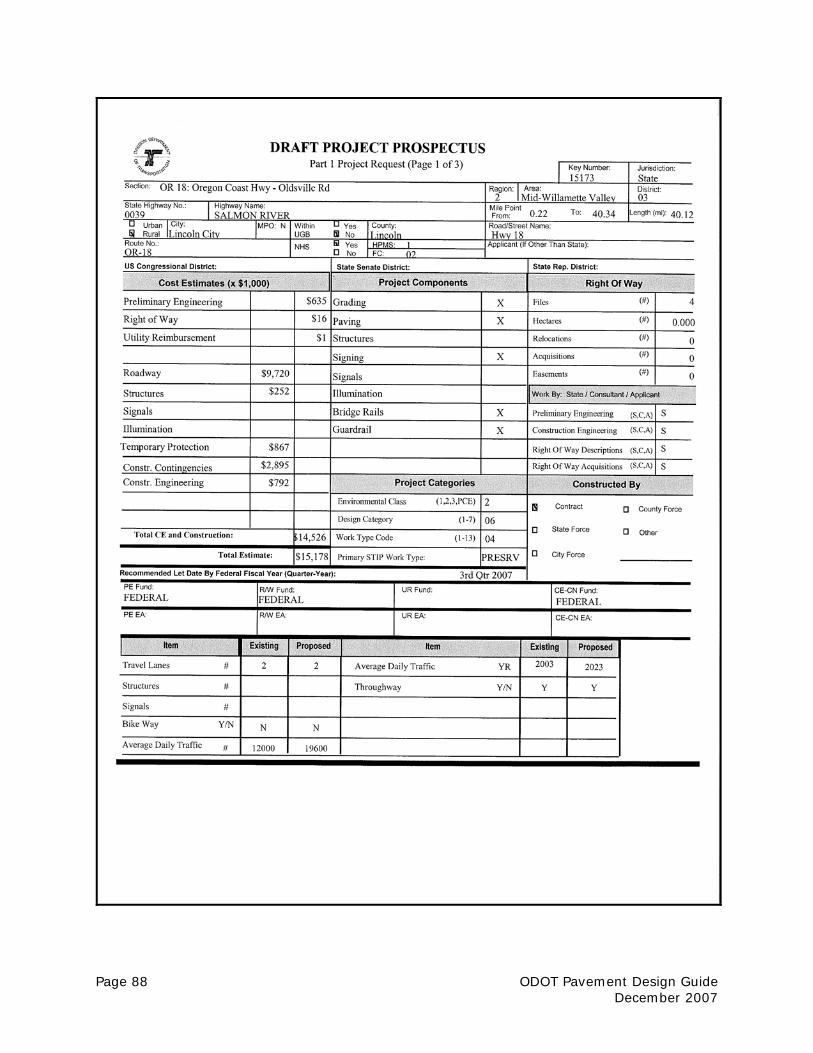
Page 88 ODOT Pavement Design Guide December 2007

ODOT Pavement Design Guide Page 89 December 2007

Page 90 ODOT Pavement Design Guide December 2007
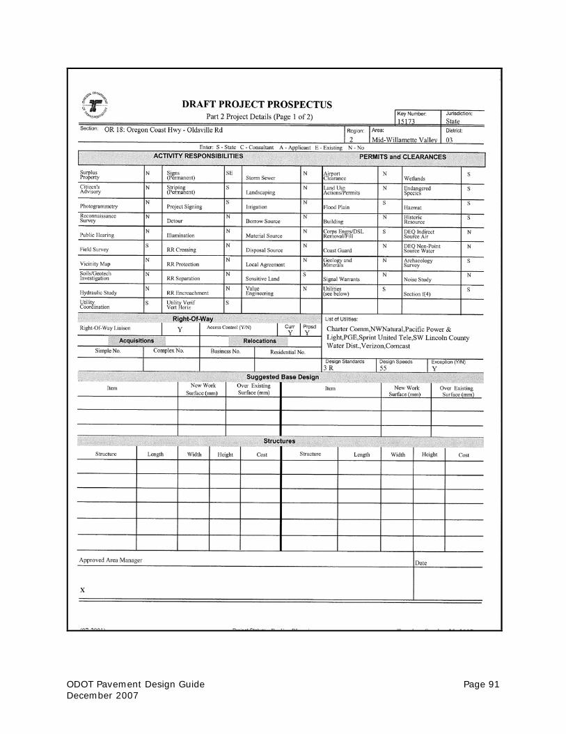
ODOT Pavement Design Guide Page 91 December 2007
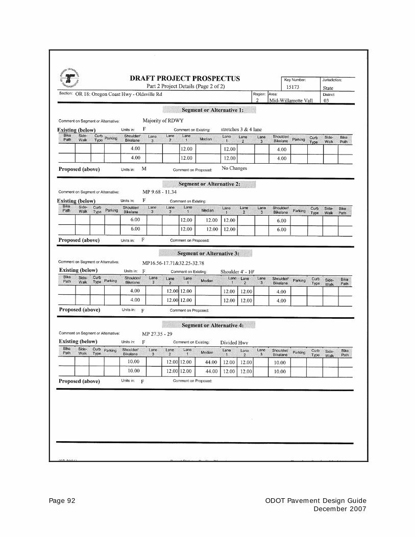
Page 92 ODOT Pavement Design Guide December 2007

ODOT Pavement Design Guide Page 93 December 2007
APPENDIX C
Pavement Depth Core Log These ODOT core logs are provided as an example only. The intent is to show the type of information that should be included on the logs. Consultants may copy the ODOT logs or develop their own form. Information to include on the core log should include:
• Lift line locations • Delamination locations (breaks caused by coring operation should be so noted) • General crack locations • Changes in core shape or areas of non-recovered material
The core condition should be visually rated by lifts:
• Good – Lift is recovered intact, tight vertical cracks may be present, no vertical or horizontal deformation
• Fair – Lift is recovered essentially intact, some single cracks may be present,
small hairline cracks may be present, small void pockets may be visible, minor spots of AC stripping or PCC deterioration, some minor deformation but stable
• Poor – Lift is not recovered intact, lift has lost core shape, recovered material is
loose (AC stripping or PCC deterioration)

Page 94 ODOT Pavement Design Guide December 2007
This page intentionally left blank.

ODOT Pavement Design Guide Page 95 December 2007
PROJECT: Saved: Yes NoHIGHWAY: PD #
LOCATION: Date:
CORE LENGTH: Logged By:Key No.: Designer:
DRILLED THROUGH PATCH: NO YES
DRILLED ON CRACK: NO YES (Trans. Long. Fat. Other):
TYPE: Dense AC Open AC PCC CTB Oil Mat OtherCONDITION: Good Fair Poor
TYPE: Dense AC Open AC PCC CTB Oil Mat OtherCONDITION: Good Fair Poor
TYPE: Dense AC Open AC PCC CTB Oil Mat OtherCONDITION: Good Fair Poor
TYPE: Dense AC Open AC PCC CTB Oil Mat OtherCONDITION: Good Fair Poor
TYPE: Dense AC Open AC PCC CTB Oil Mat OtherCONDITION: Good Fair Poor
TYPE: Dense AC Open AC PCC CTB Oil Mat OtherCONDITION: Good Fair Poor
TYPE: Dense AC Open AC PCC CTB Oil Mat OtherCONDITION: Good Fair Poor
NOTE DISTANCE FROM EDGE OF PAVEMENT AND DIRECTION
4 62 3
1
2
0 1
3
4
5
6
13
14
7
8
9
10
24
19
20
21
22
PAVEMENT CORE LOG
23
15
16
17
18
11
12
EP EP

Page 96 ODOT Pavement Design Guide December 2007
1. Fill in all appropriate blanks in the header. Some of these will be the same for all corestaken on a particular project and may be filled out ahead of time. Use of a printer orcopy machine to make multiple copies is recommended.
2. The PD # in the top right corner of the sheet is the number of the core represented by the log sheet. Number the sheets 1, 2, 3, etc. Start over at 1 for each project.
3. Identify if the core was cut through a patch and if it was cut through a crack suchas transverse, longitudinal, or fatigue by circling the appropriate entry.
4. Draw a graphical representation of the core that includes all cracks, delamainations,lift lines, and stripping.
A. Cracks: If the crack is tight (closed) and the two sides still attached, draw as a single irregular line.If the two sides are detached (open), show as as two narrowly spaced and parallel irregular lines.
B. Delaminations: Show as two narrowly spaced and parallel horizonatal lines.C. Lift lines: Single horizonatal line.D. Stripping: Stripping should be shown as a series of small irregular circles depicting the
presence of stripped aggregate. Do not try to replicate each individual piece of aggregate.
5. At the bottom of the page fill in the physical data for the core location.A. Under the arrow indicate the direction of the lane in which the core is taken.B. Indicate the approximate locations of existing striping.C. Indicate by a small box the approximate location where the core was cut.D. Measure distances from the edge of the pavement to the different stripes, to the core
location, and to the far edge of the pavement. Indicate these distances in feet and inches .
Open crackLift lineClosed crack
Delamination
Stripping
PAVEMENT SERVICES UNIT
CORE LOG INSTRUCTIONS

ODOT Pavement Design Guide Page 97 December 2007
PROJECT: Saved: Yes NoHIGHWAY: PD #MILEPOINT; Date:LOCATION: Logged By:CORE LENGTH: inches EB on r a m p ( l oop) a t
11 .5 " t o bot t om Cor n el i u s Pa ss Roa d . Designer:of CTB? EA #:
Key #:
DRILLED THROUGH PATCH: NO YES
DRILLED ON CRACK: NO YES (Trans. Long. Fat. Other):
TYPE: Dense AC Open AC PCC CTB Oil Mat OtherCONDITION: Good Fair Poor
TYPE: Dense AC Open AC PCC CTB Oil Mat OtherCONDITION: Good Fair Poor
TYPE: Dense AC Open AC PCC CTB Oil Mat OtherCONDITION: Good Fair Poor
St r i pped ou t TYPE: Dense AC Open AC PCC CTB Oil Mat OtherCTB CONDITION: Good Fair Poorbel ow.
TYPE: Dense AC Open AC PCC CTB Oil Mat OtherCONDITION: Good Fair Poor
TYPE: Dense AC Open AC PCC CTB Oil Mat OtherCONDITION: Good Fair Poor
TYPE: Dense AC Open AC PCC CTB Oil Mat OtherCONDITION: Good Fair Poor
Not e: St r i pped ou t CTBi n ba g w/ cor e.
NOTE DISTANCE FROM EDGE OF PAVEMENT AND DIRECTION
RogerPE001249/000/J13
MP 62.46631 '6" W. o f X- wa l k on Cor n el i u s Pa ss Rd . on r a m p EB.
7 .0
481/24/2007
Craigh Michael
Travis
N.PLAINS - CORNELL ROADSUNSET HWY. NO. 47
PAVEMENT CORE LOG
23
15
16
17
18
11
12
24
19
20
21
22
13
14
7
8
9
10
3
4
5
6
2 3
1
2
0 1 137074 5 6
EP EP
X
EN S
W
EB
4 1 / 2" cu r b F/ LS/ SF/ L
Cor e
7.3 '11.3 '21.2 '34.0 '38.0 '
Cor n el i u s Pa ss Rd .

Page 98 ODOT Pavement Design Guide December 2007
CORE #48

ODOT Pavement Design Guide Page 99 December 2007
APPENDIX D
Exploration Hole Log These ODOT exploration logs are provided as an example only. The intent is to show the type of information that should be included on the logs. Consultants may copy the ODOT logs or develop their own form.

Page 100 ODOT Pavement Design Guide December 2007
This page intentionally left blank.
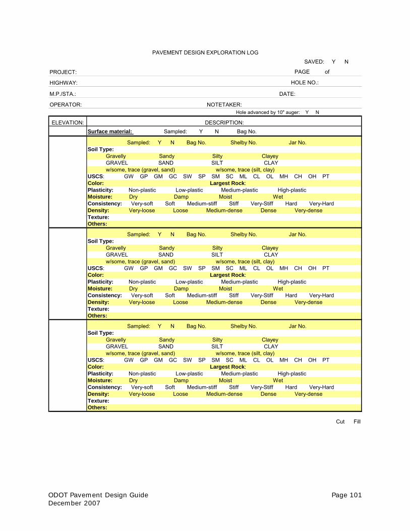
ODOT Pavement Design Guide Page 101 December 2007
SAVED: Y N
PROJECT: PAGE of
HIGHWAY: HOLE NO.:
M.P./STA.: DATE:
OPERATOR: NOTETAKER:Hole advanced by 10" auger: Y N
ELEVATION: DESCRIPTION:Surface material: Sampled: Y N Bag No.
Sampled: Y N Bag No. Shelby No. Jar No.Soil Type: Gravelly Sandy Silty Clayey GRAVEL SAND SILT CLAY w/some, trace (gravel, sand) w/some, trace (silt, clay) USCS: GW GP GM GC SW SP SM SC ML CL OL MH CH OH PTColor: Largest Rock:Plasticity: Non-plastic Low-plastic Medium-plastic High-plasticMoisture: Dry Damp Moist WetConsistency: Very-soft Soft Medium-stiff Stiff Very-Stiff Hard Very-HardDensity: Very-loose Loose Medium-dense Dense Very-denseTexture:Others:
Sampled: Y N Bag No. Shelby No. Jar No.Soil Type: Gravelly Sandy Silty Clayey GRAVEL SAND SILT CLAY w/some, trace (gravel, sand) w/some, trace (silt, clay) USCS: GW GP GM GC SW SP SM SC ML CL OL MH CH OH PTColor: Largest Rock:Plasticity: Non-plastic Low-plastic Medium-plastic High-plasticMoisture: Dry Damp Moist WetConsistency: Very-soft Soft Medium-stiff Stiff Very-Stiff Hard Very-HardDensity: Very-loose Loose Medium-dense Dense Very-denseTexture:Others:
Sampled: Y N Bag No. Shelby No. Jar No.Soil Type: Gravelly Sandy Silty Clayey GRAVEL SAND SILT CLAY w/some, trace (gravel, sand) w/some, trace (silt, clay) USCS: GW GP GM GC SW SP SM SC ML CL OL MH CH OH PTColor: Largest Rock:Plasticity: Non-plastic Low-plastic Medium-plastic High-plasticMoisture: Dry Damp Moist WetConsistency: Very-soft Soft Medium-stiff Stiff Very-Stiff Hard Very-HardDensity: Very-loose Loose Medium-dense Dense Very-denseTexture:Others:
Cut Fill
PAVEMENT DESIGN EXPLORATION LOG

Page 102 ODOT Pavement Design Guide December 2007

ODOT Pavement Design Guide Page 103 December 2007
APPENDIX E
Bridge Approach Testing Deflection Testing and Coring at Bridge Approaches * = Deflection tests at the following intervals: 5’, 10’, 20’, 30’, 40’, 50’, 75’, 100’, 125’, 150’, 200’. = Pavement Cores. Pavement Cores at the same locations as the 10’ and 50’ deflection tests. Do not deflect or core on impact panels. For our testing purposes impact panels are considered part of the structure.
200' 150'
125'
75'
30'40'
50'
100'
Bridge
No Impact Panel
* * * * *
5'10' 20'
* * ***
150'125'
100'75'
50'40'
30'20'
10'5'
Impact Panel
200'
** * * * * * * * * *

Page 104 ODOT Pavement Design Guide December 2007
This page intentionally left blank.

ODOT Pavement Design Guide Page 105 December 2007
APPENDIX F
At-Grade Railroad Crossing Testing Deflection Testing and Coring at Railroad Crossing Approaches
( ) Deflection tests at the following intervals: 5', 10', 20', 30', 40', 50', 75', 100', 125', 150', 200'.
( ) Pavement cores.
Note: The specific quantities and locations of tests may vary from the drawing above basedon specific site conditions.
FIELD WORK @ RR CROSSINGS
20'
30'40'
50'
75'
100'
125'
150'200'
20'
30'
40'
50'
75'
100'
125'
150'200'
Stop Bar
* * * * * * * * **********
*
Stop Bar
** *
10'
5'5'
10'
* RR
RR

Page 106 ODOT Pavement Design Guide December 2007
This page intentionally left blank.

ODOT Pavement Design Guide Page 107 December 2007
APPENDIX G
Objective Rating Distress Type Descriptions The Pavement Management Group has developed a pavement condition survey manual that provides a detailed description of the Objective Rating process as well as the pavement distress type descriptions. Excerpts of the manual are provided in this appendix. For the full manual, visit the Pavement Management website: http://www.oregon.gov/ODOT/HWY/CONSTRUCTION/pavement_management_sys.shtml

Page 108 ODOT Pavement Design Guide December 2007
This page intentionally left blank.

ODOT Pavement Design Guide Page 109 December 2007
OREGON DEPARTMENT OF TRANSPORTATION Pavement Management Group Distress Survey Manual INTRODUCTION • This manual in conjunction with the SHRP Distress Identification Manual for the Long-Term
Pavement Performance Project (SHRP-P-338) outlines the procedure for conducting distress surveys. The purpose of the distress surveys is to identify and quantify the amount and severity of surface distress in a given segment of pavement. The results of the distress survey are used along with other measured pavement characteristics to establish a condition rating for the roadway segment.
• The Oregon State Highway System is currently composed of three primary surface types; Asphalt Concrete (AC), Jointed Portland Cement Concrete Pavement (JCP), and Continuously Reinforced Portland Cement Concrete Pavement (CRCP). The distress types and procedures for rating each of these pavement types are presented in this manual.
SECTION 1
ASPHALT CONCRETE (AC) PAVEMENTS The evaluation of asphalt pavements will be completed by rating the distress in the pavement according to the SHRP descriptions and severity levels as summarized below. DISTRESS TYPES • Rutting • Fatigue Cracking • Longitudinal Cracking • Transverse Cracking • Block Cracking • Potholes and Patches • Raveling • Bleeding RUTTING (AC - JCP - CRCP) Rutting is a longitudinal surface depression in the wheel path caused by permanent deformation (AC only) or the wearing away of the pavement surface. The rut depth will be categorized as zero, low, moderate, or high according to the following criteria:
Identification - Longitudinal surface depression in wheel path Severity Level Zero = 0” < 1/4” Low = 1/4” < 1/2” Mod = 1/2” < 3/4” High ≥ 3/4”

Page 110 ODOT Pavement Design Guide December 2007
FATIGUE CRACKING Fatigue cracking, also known as alligator cracking, is a single crack or series of interconnected cracks caused by fatigue failure of the asphalt concrete. Longitudinal cracks in the wheel path are rated as fatigue cracks.
Identification - Occurs in areas subjected to repeated traffic loading (wheel paths). Can be a series of interconnected cracks in early stages of development. Develops into many-sided, sharp-angled pieces, usually less than 0.3 meters longest side. Characteristically has chicken wire/alligator pattern in later stages. Severity Levels Low - An area of cracks with no or only a few connecting cracks; Cracks must not be spalled; No pumping is evident. Moderate - An area of interconnected cracks forming a complete pattern; Cracks may be slightly spalled; No pumping is evident. High - An area of moderately or severely spalled interconnected cracks forming a complete pattern; Cracks may be sealed; Pieces may move when subjected to traffic; Pumping may be evident
LONGITUDINAL CRACKING Longitudinal cracks are cracks that are parallel to the pavement’s centerline. Only longitudinal cracks that are not in a wheel path should be recorded as this form of distress. Longitudinal cracks which occur in the wheel path should be rated as fatigue cracking.
Identification - Cracks predominantly parallel to pavement centerline. Location within the lane (non-wheel path) is significant. Severity Levels Low - A crack with a mean width of < 0.25”; or a sealed crack with sealant material in good condition and a width that cannot be determined. Moderate - Any crack with a mean width ≥ 0.25” and < 0.75”; or any crack with a mean width < 0.75 in and adjacent low severity random cracking. High - Any crack with a mean width ≥ 0.75”; or any crack with a mean width < 0.75” and adjacent moderate to high severity random cracking.
TRANSVERSE CRACKING Transverse cracks are predominantly perpendicular to the pavement centerline, and may extend all or part way across the travel lane. The amount of transverse cracking will be measured by counting the actual number of cracks that occur in the travel lane being rated. Cracks must extend at least half way across the travel lane before being counted.
Identification - Cracks predominantly perpendicular to pavement centerline. Severity Levels Low - An unsealed crack with a mean width of < 0.25”; or a sealed crack with sealant material in good condition and the width cannot be determined. Moderate - Any crack with a mean width ≥ 0.25” and < 0.75”; or any crack with a mean width < 0.75” and adjacent low severity random cracking. High - Any crack with a mean width ≥ 0.75”; or any crack with a mean width < 0.75” and adjacent moderate to high severity random cracking.

ODOT Pavement Design Guide Page 111 December 2007
BLOCK CRACKING Block cracking is a distress where cracks divide the pavement surface into approximately rectangular pieces. These pieces are typically one to 100 square feet. Block cracking, unlike fatigue cracking, will typically occur throughout the pavement width, not just in the wheel tracks. The amount of block cracking will be visually estimated as to the square feet of the travel lane that suffers this distress.
Identification - A pattern of cracks that divide the pavement into approximately rectangular pieces or blocks. Blocks range in size from approximately 1 ft2. to 100 ft2. Severity Levels Low - Cracks with a mean width of < 0.25”; or sealed cracks with sealant material in good condition and the width cannot be determined. Moderate - Cracks with a mean width ≥ 0.25” and < 0.75”; or any crack with a mean width < 0.75” and adjacent low severity random cracking. High - Cracks with a mean width ≥ 0.75”; or any crack with a mean width < 0.75” and adjacent moderate to high severity random cracking.
POTHOLES AND PATCHES Potholes and patches will be rated together. The amount of potholes and patching in any one segment will be visually estimated as to the square feet of the travel lane experiencing this distress.
Identification (Pothole) - Bowl-shaped holes of various sizes in the pavement surface. Minimum plan dimension is 6”.
Severity Levels Low < 1” Mod ≥ 1 < 2” High ≥ 2”
Identification (Patch) - Portion of pavement surface, greater than 1-ft2 that has been removed and replaced or additional material applied to the pavement after original construction.
Severity Levels
Low - Patch has at most low severity distress of any type. Moderate - Patch has moderate severity distress of any type. High - Patch has high severity distress of any type.
RAVELING Raveling is the wearing away of the pavement surface caused by the dislodging of coarse aggregate particles. It is a progressive disintegration from the surface downward, usually as the result of traffic action. The severity of raveling is based on the estimated percentage of aggregate loss in a 1’ wide longitudinal strip of pavement surface as described below. The quantity of raveling will be estimated based on the linear feet of raveling occurring in the inside wheel path, outside wheel path, and between the wheelpaths. Identification - Raveling can be identified by a roughened or pitted texture on the pavement surface. Mechanical abrasion from tire chains, studs, snowplows, or dragging equipment which significantly roughens up the texture should be rated as raveling. Studded tire rutting which does not roughen up the texture

Page 112 ODOT Pavement Design Guide December 2007
significantly should not be rated as raveling. Raveling tends to be most often found in the wheel paths, but can be elsewhere on the pavement surface.
Severity Level - For all surface types, raveling is not rated if less than 25% of the surface in a given 1’ wide strip is affected. NOTE - Chip Seals are normally rough textured - only rate as low severity raveling if there is ≥25% aggregate loss present in a 1’ wide strip. Low - The coarse aggregate has worn away resulting in ≥25% to <50% aggregate loss in a 1’ wide longitudinal strip of pavement surface. Loss of chip seal rock should be rated as raveling, but this is the maximum severity for chip sealed surfaces. Moderate - Surface texture is noticeably rough and/or pitted with ≥50% to <75 % aggregate loss in a 1’ wide longitudinal strip of pavement surface. A nearly continuous strip of aggregate loss 3” – 6” wide may be present. Loose particles may be present outside the traffic area. High - Surface texture is very rough and/or pitted with ≥75% aggregate loss in a 1’ wide longitudinal strip of pavement surface. Flat bottom potholes may be present where complete loss of aggregate has occurred. BLEEDING Bleeding is indicated by the excess bituminous material on the pavement surface, which creates a shiny, glass-like reflective surface which usually becomes sticky in hot temperatures. Bleeding is not rated by severity level, but should be recorded when it is severe enough to cause a reduction in skid resistance. A segment is considered to have measurable bleeding if it has multiple areas ≥ 25 square feet of bleeding. Bleeding will simply be recorded as either existing or not existing for each 0.1-mile segment.
Identification - Excess bituminous binder on pavement surface. May create a shiny, glass-like, reflective surface that may be tacky to the touch. Usually found in the wheelpaths.
Severity Levels - Bleeding is present if multiple areas of 25 ft2 or larger patches.
How to Measure - Recorded as either existing or not existing (Yes/No)

ODOT Pavement Design Guide Page 113 December 2007
SECTION 2 JOINTED CONCRETE PAVEMENTS (JCP)
The evaluation of jointed concrete pavements will be completed by rating the distress in the pavement according to the SHRP descriptions and severity levels as summarized below. DISTRESS TYPES • Rutting (See AC Pavement Section) • Corner Crack • Corner Break • Longitudinal Cracking • Transverse Cracking • Shattered Slab • Patch Condition • Joint Condition CORNER CRACKING Corner cracks are cracks of any length that begin at transverse joints and are predominantly parallel to the pavement centerline. These cracks are located anywhere from the edge of the PCC up to and including the wheel path. Corner crack severity is based on crack width, spalling or faulting. The amount of corner cracking will be measured by counting the number of cracks that occur in each tenth-mile segment. Corner cracks that intersect transverse cracks will be rated as corner breaks and not as corner cracks.
Identification - A crack which begins at a transverse joint and radiates outward predominantly parallel to the pavement centerline. Located anywhere from the PCC edge to and including the wheel path.
Severity Levels
Low – Crack widths < 0.125”, no spalling, and no measurable faulting; or well sealed and with a width that cannot be determined. Moderate – Crack widths > 0.125” and < 0.5”; or with spalling < 3”; or faulting up to 0.5”. High – Crack widths > 0.5”; or with spalling > 3”; or faulting > 0.5”.
How to Measure - Record the number of corner cracks at each severity level

Page 114 ODOT Pavement Design Guide December 2007
CORNER BREAK A corner break is the separation of a corner portion of concrete from the rest of the PCC slab. Corner breaks occur when a corner crack is intersected by a transverse crack or when a diagonal crack extends across the corner of a slab. Corner break severity is based on spalling, faulting, or number of broken pieces, not crack width. The amount of corner breaks will be measured by counting the number of breaks that occur in each segment.
Identification - A crack which separates the slab and intersects the adjacent transverse and longitudinal joints, describing an approximate 45 degree angle with the direction of traffic. Not included are cracks that are within one foot of the edge and less than 1 foot long.
Severity Levels
Low – Crack is not spalled or is spalled for <10 % of the length of the crack; no measurable faulting; and corner piece is not broken into two or more pieces. Moderate – Crack is spalled at low severity (< 3”) for >10% of its total length; or faulting of crack or joint is < 0.5”; and the corner piece is not broken. High – Crack is spalled at moderate (> 3” and < 6”) to high severity ≥ 6” for >10 % of its total length; or faulting is ≥ 0.5”; or the corner piece is broken into two or more pieces.
How to Measure - Record the number of corner breaks at each severity level. LONGITUDINAL CRACKS Longitudinal cracks are cracks that are predominantly parallel to the pavement centerline. Only longitudinal cracks that are not classified as corner cracks should be recorded as this form of distress (see description of corner cracks). Longitudinal cracks do not start at the joint, or if they start at the joint they are in the center of the lane between wheel paths. The crack severity is based on width, spalling, and faulting.
Identification - Cracks that are predominately parallel to the pavement centerline. Only cracks that are not corner cracks (intersecting transverse joints) should be recorded
Severity Levels
Low – Crack widths < 0.125”, no spalling, and no measurable faulting; or well sealed and with a width that cannot be determined. Moderate – Crack widths > 0.125” and < 0.5”; or with spalling < 3”; or faulting up to 0.5”. High – Crack widths > 0.5”; or with spalling > 3”; or faulting > 0.5”. How to Measure - Record the linear feet in each severity level

ODOT Pavement Design Guide Page 115 December 2007
TRANSVERSE CRACK Transverse cracks are cracks that are predominantly perpendicular to the pavement centerline. These cracks extend all or part way across the travel lane. Transverse crack severity is based on crack width, spalling and faulting. The amount of transverse cracking will be measured by counting the actual number of cracks that occur in the travel lane being rated.
Identification - Cracks that are perpendicular to the pavement centerline.
Severity Levels
Low – Crack width < 0.125 inches, and no spalling, and no measurable faulting; or well-sealed and width cannot be determined. Moderate – Crack widths ≥ 0.125 inches and < 0.25 inches; or with spalling < 3 inches; or faulting up to 0.25 inches. High – Crack widths ≥ 0.25 inches; or with spalling ≥ 3 inches; or faulting ≥ 0.25 inches.
How to Measure - Record the number of cracks at each severity. Rate the entire transverse crack at the highest severity level present for at least 10% of the total length of the crack. Cracks should extend at least half way across the travel lane before being counted.
SHATTERED SLAB A shattered slab is a concrete slab that is broken into three or more pieces. Slabs that are divided solely by transverse cracks are not included. Corner breaks are also not included. The severity of a shattered slab is determined by the number of pieces the slab is broken into combined with the severity of spalling and faulting exhibited. The quantity of shattered slabs will be measured by counting the number that occurs in each 0.1-mile segment.
Identification - A concrete slab that is broken into three or more pieces. Do not include corner breaks when counting broken slab sections. Also do not include slab sections that are divided by one or more transverse cracks.
Severity Levels
Low – Slab is broken into 3 pieces. The cracks describing the broken sections are not spalled or are spalled for <10 % of the length of the crack; no measurable faulting. Moderate – Slab is broken into 4 pieces; or the cracks describing the broken sections are spalled at low severity (< 3”) for >10% of its total length; or faulting is < 0.5”. High – Slab is broken into 5 or more pieces; or the cracks describing the broken sections are spalled > 3” for >10 % of its total length; or faulting is ≥ 0.5”.
How to Measure - Record the number of shattered slabs at each severity level.

Page 116 ODOT Pavement Design Guide December 2007
PATCH CONDITION A patch is an area where the original pavement has been removed and replaced, or additional material applied to the pavement after original construction. If patch material is non-concrete, the patch will be rated as high severity. The patch severity is based on distresses present in the patch or faulting. The amount of patching will be measured by estimating the square feet of the outside lane that is patched.
Identification - A portion or all of the original concrete slab that has been removed and replaced, or additional material applied to the pavement after original construction. Severity Levels Low – Patch has at most low severity distress of any type; and no measurable faulting or settlement; pumping is not evident. Moderate – Patch has moderate severity distress of any type; or faulting or settlement to 0.25 inches; pumping is not evident. High – Patch has a high severity distress of any type; or faulting or settlement ≥ 0.25 inches; pumping may be evident. Also includes patches that are not made with concrete materials.
How to Measure - Record the square feet at each severity level. JOINT CONDITION Rating is based on a combination of the joint and joint seal condition. The condition of the transverse, lane, and shoulder joints will be rated separately based on the average condition of the joints in each segment, as follows:
Severity Level Low - Joint is in good condition and seal is in good condition. Mod - Joint is slightly spalled with seal in good condition or joint is in good condition with seal in poor condition. High - Joint is badly spalled or joint is slightly spalled with seal in poor condition.

ODOT Pavement Design Guide Page 117 December 2007
SECTION 3 CONTINUOUSLY REINFORCED CONCRETE PAVEMENTS (CRCP)
The evaluation of continuously reinforced concrete pavements will be completed by rating the distress in the pavement according to the SHRP descriptions and severity levels as summarized below. DISTRESS TYPES • Rutting (See AC Pavement Section) • Longitudinal Cracking • Transverse Cracking • Punchouts • Potholes and Patches • Joint Condition LONGITUDINAL CRACK Longitudinal cracks are cracks that are predominantly parallel to the pavement centerline. The crack severity is based on width, spalling, and faulting, and is adjusted for load related cracking.
Identification - Cracks that are predominately parallel to the pavement centerline. For CRCP, the severity level is "bumped" up to the next level if the crack is load related, in accordance with the definition below.
Non-Load Related - Majority of crack out of wheeltrack; Within 1' of the lane or shoulder joint, or Within 1' of the middle of the lane; Note - Crack may meander into wheeltrack but generally stays out of the wheeltrack Load Related - Majority of crack in the wheeltrack (area excluded in above definition); Shape is typically linear and parallel to lane, although may be diagonal or crescent shaped. All load related cracks are rated as either moderate or high severity
Severity Levels
Low – Non-load related cracks with a width < 0.125”, no spalling, and no measurable faulting; or well sealed and with a width that cannot be determined. Low load-related cracks are bumped to moderate. Moderate – Crack widths ≥ 0.125” and < 0.5”; or with spalling < 3”; or faulting up to 0.5”. Also includes low severity load related cracks. Moderate load-related cracks are bumped to high. High – Crack widths ≥ 0.5”; or with spalling ≥ 3”; or faulting ≥ 0.5”. Also includes moderate severity load related cracks. How to Measure - Record the linear feet in each severity level.

Page 118 ODOT Pavement Design Guide December 2007
TRANSVERSE CRACK Transverse cracking of continuously reinforced concrete pavement is normal and is not considered a form of distress. However, if the cracks open up, major deterioration may result. Transverse crack severity is rated based on the average crack condition in the 0.1-mile segment Also, at each milepoint marker, the average crack spacing is determined in a 100-foot section by dividing 100 by the number of cracks counted in the section.
Identification - Cracks that are perpendicular to the pavement centerline. Severity Levels Low – Cracks that are not spalled or are spalled < 10% of the crack length. Moderate – Cracks that are spalled along ≥ 10% and < 50% of the crack length. High – Cracks that are spalled along ≥ 50% of the crack length.
PUNCHOUT A punchout is the separation of a block of concrete from the rest of the CRCP formed by two closely spaced transverse cracks, a short longitudinal crack, and the edge of the pavement or longitudinal joint. As the cracks deteriorate, the steel ruptures and the block of concrete punches downward into the base and subbase. Punchouts will be rated as low, moderate, or high based on spalling or faulting. The quantity of punchouts will be measured by counting the number that occurs in each segment. If a punchout has been patched with asphalt, it should be rated as a high-severity punchout and not a patch, as the patch is only a temporary repair.
Identification - A localized separation of a block of concrete from the rest of the PCC slab. Also includes "Y" cracks that exhibit spalling, breakup, and faulting. Longitudinal crack defining the block may be any length. Adjacent transverse cracks may be more than 2' apart. Branch portion of "Y" crack must be less than 1/2 lane.
Severity Levels
Low – Longitudinal or transverse crack are spalling < 3” or faulting < 0.25”. At least two cracks defining the block must be spalled. Does not include "Y" cracks. Moderate – Spalling ≥ 3” and < 6” or faulting ≥ 0.25 inches. Includes "Y" cracks that exhibit spalling, breakup and faulting in the branch portion of the "Y" along >10% (1' minimum) and <50% of crack length. High – Spalling ≥ 6” or concrete within the punchout is punched down by ≥ 0.5” or is loose and moves under traffic. Includes "Y" cracks that exhibit high severity spalling, breakup and faulting in the branches of the "Y" along >50% of the crack length.

ODOT Pavement Design Guide Page 119 December 2007
PATCH CONDITION A patch is an area where the original pavement has been removed and replaced with non-asphalt type of material. An asphalt patch should be rated as a high-severity punchout instead of a patch. The patch severity is based on distress in the patch, faulting or pumping. The amount of patching will be measured by estimating the square feet of the outside lane that is patched.
Identification - A portion or all of the original concrete slab that has been removed and replaced with a permanent (concrete) type of material. An asphalt patch should be rated as a high-severity punchout instead of a patch.
Severity Levels
Low – Patch has at most low severity distress of any type; and no measurable faulting or settlement at the perimeter of the patch. Moderate – Patch has moderate severity distress of any type; or faulting or settlement < 0.25 inches at the perimeter of the patch. High – Patch has a high severity distress of any type; or faulting or settlement ≥ 0.25 inches at the perimeter of the patch.
JOINT CONDITION Rating is based on a combination of the joint and joint seal condition. The condition of the transverse, lane, and shoulder joints will be rated separately based on the average condition of the joints in each segment, as follows:
Severity Level Low - Joint is in good condition and seal is in good condition. Mod - Joint is slightly spalled with seal in good condition or joint is in good condition with seal in poor condition. High - Joint is badly spalled or joint is slightly spalled with seal in poor condition.

Page 120 ODOT Pavement Design Guide December 2007
This page intentionally left blank.

ODOT Pavement Design Guide Page 121 December 2007
APPENDIX H
Sample Distress Rating Form This ODOT Pavement Design distress rating form is provided as an example only. The intent is to show the type of information that should be included on the form. Consultants may copy the ODOT logs or develop their own form.

Page 122 ODOT Pavement Design Guide December 2007
PRO
JEC
T:PA
GE:
HW
Y.:
DAT
E:
BOP:
toEO
P:
DIR
ECTI
ON
RA
TED
: R
ATE
R'S
NA
ME
:
BEG
INEN
DFL
US
H.
LAN
ESM
PM
PL
MH
LM
HL
MH
LM
HL
MH
LM
H
C =
Con
tinuo
us
E
= E
xten
sive
I =
Inte
rmitt
ent
S =
Spor
adic
V =
Ver
y c:
\usr
\form
s\ra
ting
form
FATI
GU
ETR
ANS.
MAP
CR
AC
KIN
GR
AVE
LIN
GP
ATC
HES
RU
TSC
OM
ME
NTS

ODOT Pavement Design Guide Page 123 December 2007
APPENDIX I
Example ESAL Calculation Given: State Highway with Asphalt Concrete Pavement
Construction Year = 2004 20-year Structural Design Life Traffic Data as provided by the ODOT Traffic Planning and Analysis Unit (contact phone number 503-986-4251):
2000 Two-way ADT = 13,400 2020 Two-way ADT = 19,300 20-year Expansion Factor = 1.44 Note – 20-year Expansion Factor = (2020 ADT)/(2000 ADT)
Truck Count From ODOT Traffic Planning and Analysis Unit 2 axle 3 axle 4 axle + 4 axle - 5 axle S 6 axle S 5 axle D 6 axle D 7 axle + Total %Trucks 350 200 4 80 140 55 5 5 20 859 6.4
Required: Determine 20-year Design ESAL’s for input into AASHTO Pavement Design
Procedure. Solution: 1) Determine Annual Growth Rate from the 20-year Expansion Factor:
100*1-E=Rn1)(
][
Where: R = Annual Growth (%) E = Expansion Factor n = Number of Years
84.1=100*1-44.1=R201 )(
][
Annual Growth = 1.84%
2) Perform Initial ESAL Calculation for the year 2000:
*Note – ODOT performs ESAL calculations based on number of axles. All two-axle trucks are combined; all three-axle trucks are combined etc. Trucks with six or more axles are combined into the six-axle group.
Number of
Axles Truck Count × Conversion Factor
(Table 2) = Year 2000 ESAL’s
2 350 × 50 = 17,500 3 200 × 110 = 22,000 4 84 × 160 = 13,440 5 145 × 325 = 47,125 6+ 80 × 325 = 26,000 Total = 859 Total = 126,065

Page 124 ODOT Pavement Design Guide December 2007
3) Expand Initial ESAL Calculation to Year of Construction:
(2004 in this example)
Year 2000 ESAL’s = 126,065 Annual Growth Rate = 1.84%
⎥⎦
⎤⎢⎣
⎡⎟⎠⎞
⎜⎝⎛+= n][ )(
1001 RE n
Where: R = Annual Growth (%) En = Expansion Factor to year n n = Number of Years
⎥⎦
⎤⎢⎣
⎡=⎟
⎠⎞
⎜⎝⎛+= 076.1
10084.114
4][ )(E
2004 ESAL’s = (2000 ESAL’s) * (4-yr Expansion Factor) 2004 ESAL’s = (126,065) * (1.076) = 135,646
4) Forecast ESAL’s to end of Design Life:
(20 years in this example) Example Calculation
100R
+1s2004ESAL'=s2005ESAL' ][ )(
142,138100
84.11646,135'2005 =⎟⎟⎠
⎞⎜⎜⎝
⎛⎟⎠⎞
⎜⎝⎛+= ][ )(sESAL
Year ESAL's Summation2004 135,646 135,6462005 138,142 273,7882006 140,684 414,4722007 143,272 557,7442008 145,908 703,6522009 148,593 852,2462010 151,327 1,003,5732011 154,112 1,157,6852012 156,947 1,314,6322013 159,835 1,474,4672014 162,776 1,637,2432015 165,771 1,803,0152016 168,821 1,971,8362017 171,928 2,143,7642018 175,091 2,318,8552019 178,313 2,497,1682020 181,594 2,678,7622021 184,935 2,863,6972022 188,338 3,052,0352023 191,803 3,243,8392024 195,333 3,439,171
20-year design ESAL’s are calculated by summing the annual ESAL’s as shown in the table to the left and subtracting the initial annual ESAL value (value for construction year). For this example the 20-year design ESAL’s are 3,439,171 – 135,646 = 3,303,525

ODOT Pavement Design Guide Page 125 December 2007
APPENDIX J
Mix Type and PG Binder Recommendation The following tables provide the recommended combinations of mix design Level, type of mix (aggregate size designation), and performance graded (PG) binder selection. In addition, information is provided for consideration. When considering the option(s) provided, the Designer should determine the most cost-effective selection considering such elements as:
• Quantities (tons) of resulting mixes • Number of mix types (levels and aggregate sizes) for the project • Types and quantities (tons) of PG binder for the project • Availability of mix and constituents
The table provides for possible situations for consideration of PG 76-xx binder. Project experience with PG 76 grades in Oregon is limited. Contact the ODOT Pavement Materials Engineer before selecting a PG 76-xx grade. As an example, a project in the coastal area requires 2,000 tons of HMAC dense graded mixture. The 20-year ESALs is 4 million. The location is designated as Urban. The design thickness is 8 inches.
Option 1: Use full depth Level 3, ½” dense, PG 70-22. Option 2: Use Level 3, ½” dense, PG 70-22 for the top 4 inches, and Level 3, ½” or ¾” dense, PG 64-22 for the lower 4 inches. Recommendation: Option 1, since Option 2 will require two lots, and each lot will be only 1,000 tons. The effect of 2 small quantity lots would offset any cost savings from changing the aggregate size or reducing the binder grading based on factors such as: 2 mix designs, if using ¾” dense then need a course size stockpile, QC testing would provide 1 test per lot rather than 2 tests for a single lot of Option 1, etc.
Definitions: Urban Highway: A highway with slow moving traffic (less than 40 mph) or with traffic lights or other stops. Rural Highway: A highway outside of towns where traffic speeds normally exceed 40 mph and there are no traffic lights or other stops.

Page 126 ODOT Pavement Design Guide December 2007
This page intentionally left blank.

ODOT Pavement Design Guide Page 127 December 2007
Table J-1 — Western & Coastal Oregon below 2500 feet Elevation (Willamette Valley and south to Cottage Grove, Columbia River Gorge east to Hood River, & Coast Range
to Ocean)
Dense Graded HMAC 20 year ESALs Traffic Designation < 1 million 1 – 3 million >3-10 million > 10 million
Rural
Level 2, ½” Dense PG 64-22
Level 3, ½” Dense PG 64-22
Level 3, ½” Dense PG 64-22
Level 4, ½” Dense
PG 70-22
Consider: below 4” depth
Level 3 ½” or ¾” Dense
PG 64-22 (Preferred if cost-effective)
Urban
Level 2, ½” Dense PG 70-22
Level 3, ½” Dense PG 70-22
Level 3, ½” Dense
PG 70-22
Consider: below 4” depth
Level 3 ½” or ¾” Dense
PG 64-22 (Preferred if cost-effective)
Level 4, ½” Dense
PG 70-22
Consider: below 4” depth
Level 3 ½” or ¾” Dense
PG 64-22 (Preferred if cost-effective)

Page 128 ODOT Pavement Design Guide December 2007
Table J-2 — Southern Oregon below 2500 feet Elevation
(Cottage Grove south including Douglas, Josephine & Jackson Counties between Coast Range and Cascades Foothills)
Dense Graded HMAC 20 year ESALs Traffic
Designation < 1 million 1 – 3 million >3-10 million > 10 million
Rural
Level 2, ½” Dense
Wearing Course: PG 70-22
Base Course: PG 70-22
or PG 64-22 (if cost-effective)
Level 3, ½” Dense
Wearing Course: PG 70-22
Base Course: PG 70-22
or PG 64-22 (if cost-effective)
Level 3, ½” Dense
Wearing Course: PG 70-22
Base Course: PG 70-22
or PG 64-22 (if cost-effective)
Level 4, ½” Dense PG 70-22
Consider:
below 4” depth Level 3
½” or ¾” dense PG 64-22
(Preferred if cost-effective)
Urban
Level 2, ½” Dense PG 70-22
Level 3, ½” Dense
PG 70-22
Level 3, ½” Dense
PG 70-22
Level 4, ½” Dense
PG 70-22
Urban (Critical)
CONSIDER for
Stop & Go Traffic:
Level 3, ½” Dense
Wearing Course: PG 76-22
Base Course shall be: PG 70-22
CONSIDER for I-5
Urban Designation:
Top 4”: Level 4, ½” Dense
PG 76-22
Depth > 4” shall be: Level 3
½” or ¾” Dense PG 70-22

ODOT Pavement Design Guide Page 129 December 2007
Table J-3 — Central & Eastern Oregon and Western/Southern Oregon above 2500 feet Elevation (Cascade
& Siskiyou Mountains)
Dense Graded HMAC 20 year ESALs Traffic Designation < 1 million 1 – 3 million >3-10 million > 10 million
Rural
Level 2, ½” Dense PG 64-28
Level 3, ½” Dense PG 64-28
Level 3, ½” Dense
Wearing Course:
PG 70-28 Base Course:
PG 70-28 or PG 64-28 (if cost-effective)
Level 4, ½” Dense PG 70-28
Consider:
below 4” depth Level 3
½” or ¾” Dense PG 64-28
(Preferred if cost-effective)
Urban
Level 2, ½” Dense PG 64-28
Level 3, ½” Dense
Wearing Course: PG 70-28
Base Course: PG 70-28
or PG 64-28 (if cost-effective)
Level 3, ½” Dense
Wearing Course: PG 70-28
Base Course: PG 70-28
or PG 64-28 (if cost-effective)
Level 4, ½” Dense PG 70-28
Consider:
below 4” depth Level 3
½” or ¾” Dense PG 64-28
(Preferred if cost-effective)
Urban (Critical)
CONSIDER for Ontario/Vale/Nyssa Stop & Go Traffic:
Level 3, ½” Dense
Wearing Course:
PG 76-28 Base Course shall be:
PG 70-28
CONSIDER for I-84 Urban Designation:
Top 4”:
Level 4, ½” Dense PG 76-28
Depth > 4” shall be: Level 3
½” or ¾” Dense PG 70-28

Page 130 ODOT Pavement Design Guide December 2007
Table J-4 — Open Graded HMAC Wearing Course Only ½” or ¾” Mix Type
(all Classifications/Designations)
Mix Level
Western Oregon to 2500 feet Elevation & Columbia River
Gorge to Hood River
Central & Eastern Oregon
Level 2 PG 70-22 PG 70-28 Level 3 PG 70-22ER PG 70-28ER Level 4 PG 70-22ER PG 70-28ER
Small Quantities of Open-Graded Mix If Level 2 or 3 project has less than 2000 tons of open-graded mix and the only other asphalt grade needed on the project is a PG 64-22 (or PG 64-28 in Central & Eastern Oregon) you may select PG 64-22 (PG 64-28 in Central & Eastern Oregon) for the open-graded mix instead of PG 70-22 (PG 70-28). This reduces the need for small quantities of two different grades of asphalt.

ODOT Pavement Design Guide Page 131 December 2007
APPENDIX K
Executive Summary This Executive Summary is provided as an example only. The intent is to show the type of information and general format that should be included in the executive summary.

Page 132 ODOT Pavement Design Guide December 2007
This page intentionally left blank.
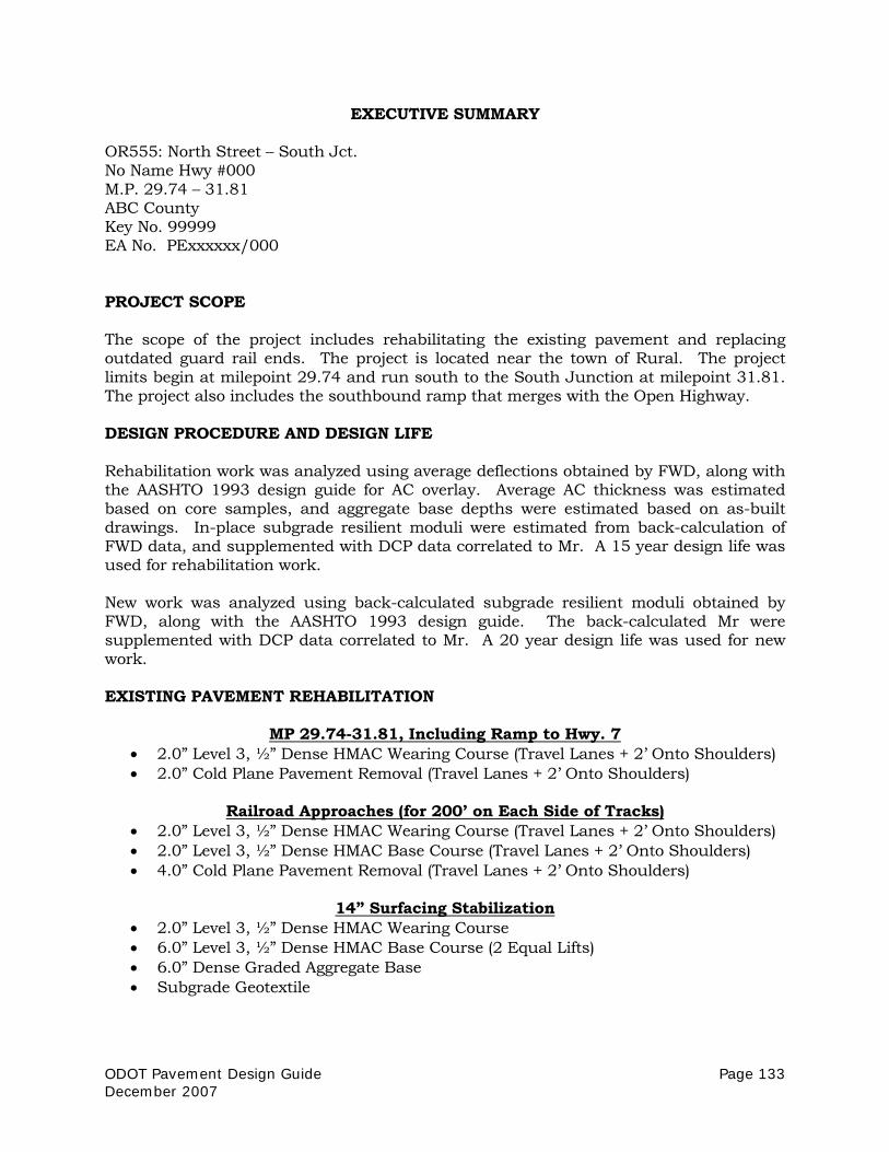
ODOT Pavement Design Guide Page 133 December 2007
EXECUTIVE SUMMARY
OR555: North Street – South Jct. No Name Hwy #000 M.P. 29.74 – 31.81 ABC County Key No. 99999 EA No. PExxxxxx/000 PROJECT SCOPE The scope of the project includes rehabilitating the existing pavement and replacing outdated guard rail ends. The project is located near the town of Rural. The project limits begin at milepoint 29.74 and run south to the South Junction at milepoint 31.81. The project also includes the southbound ramp that merges with the Open Highway. DESIGN PROCEDURE AND DESIGN LIFE Rehabilitation work was analyzed using average deflections obtained by FWD, along with the AASHTO 1993 design guide for AC overlay. Average AC thickness was estimated based on core samples, and aggregate base depths were estimated based on as-built drawings. In-place subgrade resilient moduli were estimated from back-calculation of FWD data, and supplemented with DCP data correlated to Mr. A 15 year design life was used for rehabilitation work. New work was analyzed using back-calculated subgrade resilient moduli obtained by FWD, along with the AASHTO 1993 design guide. The back-calculated Mr were supplemented with DCP data correlated to Mr. A 20 year design life was used for new work. EXISTING PAVEMENT REHABILITATION
MP 29.74-31.81, Including Ramp to Hwy. 7 • 2.0” Level 3, ½” Dense HMAC Wearing Course (Travel Lanes + 2’ Onto Shoulders) • 2.0” Cold Plane Pavement Removal (Travel Lanes + 2’ Onto Shoulders)
Railroad Approaches (for 200’ on Each Side of Tracks)
• 2.0” Level 3, ½” Dense HMAC Wearing Course (Travel Lanes + 2’ Onto Shoulders) • 2.0” Level 3, ½” Dense HMAC Base Course (Travel Lanes + 2’ Onto Shoulders) • 4.0” Cold Plane Pavement Removal (Travel Lanes + 2’ Onto Shoulders)
14” Surfacing Stabilization
• 2.0” Level 3, ½” Dense HMAC Wearing Course • 6.0” Level 3, ½” Dense HMAC Base Course (2 Equal Lifts) • 6.0” Dense Graded Aggregate Base • Subgrade Geotextile

Page 134 ODOT Pavement Design Guide December 2007
Railroad Approaches Only: Do not allow traffic on the cold-planed surfaces at the railroad approaches. Traffic may, however, be allowed on the base course for up to (3) weeks. MP 29.74-31.81, Including Ramp to Hwy. 7: Traffic may be allowed on the cold-planed surfaces for up to (3) weeks. Although no serious structural deficiencies in the existing pavement have been noted at the present time, provisions should still be made for a small quantity of surfacing stabilization (~150 yd2) in case conditions change before construction begins. NEW CONSTRUCTION
New Work Section • 2.0” Level 3, ½” Dense HMAC Wearing Course • 6.0” Level 3, ½” Dense HMAC Base Course (2 Equal Lifts) • 6.0” Dense Graded Aggregate Base • Subgrade Geotextile
Subgrade Stabilization
Provisions should be made under this contract for a quantity of Subgrade Stabilization equivalent to 50% of the total area of new construction at a depth of 18”. Subgrade Stabilization may be omitted if, upon excavation, subgrade is found to be dry and stable. Traffic should not be allowed on the new pavement before all lifts of HMAC Base Course have been paved. Traffic should not be allowed on the HMAC Base Course for more than 14 days. MATERIALS AND SPECIFICATIONS
MATERIALS/Activity SPECIFICATION (based on 2002 edition) Accomodations for Public Traffic
Include SP 00220.02 with the following: Do not allow traffic to drive on cold planed surfaces.
18”Subgrade Stabilization Special Provision 00331, aggregate subbase for backfill 14” Surfacing Stabilization Special Provision 00332 Subgrade Geotextile Special Provision 00350, Level B Certification Cold Plane Pavement Removal Special Provision 00620, Do not allow traffic to drive on
cold planed surfaces Aggregate Base Special Provision 00641 (1” – 0 or ¾” – 0) Level 3, ½” Dense HMAC Special Provision 00745. Lime or Latex Polymer
Treatment is Required. Asphalt Binder Use PG 70-28 Asphalt in Level 3, ½” Dense HMAC Material Transfer Vehicle Include SP 00745.48(b) Pavement Smoothness Do not require SP 00745.70 and related subsections
[Vicinity Map not shown]

ODOT Pavement Design Guide Page 135 December 2007
APPENDIX L
Glossary of Terms For terms not included in this glossary, refer to Section 00110.20 Definitions, of the 2002 Oregon Supplemental Specifications. Average Daily Traffic (ADT)
Number of vehicles traveling on a roadway during an average day. ADT is determined by either an automatic or manual count. ADT may include traffic in one direction (one-way ADT) or traffic in both directions (two-way ADT).
Back-Calculation
A method of determining the pavement layer moduli from measured surface deflections and known layer thicknesses. This procedure is typically used with deflection data to estimate the subgrade resilient modulus.
Designer The ODOT technical staff responsible for pavement design, or the professional consultant under contract with ODOT to provide pavement design services.
Emulsified Asphalt Concrete (EAC)
A mixture of emulsified asphalt and graded aggregate. Sometimes referred to as “Cold mix”.
Equivalent Single-Axle Load (ESAL)
A unit of measure for evaluating traffic for the development of a pavement design. More information can be found in the AASHTO Guide for Design of Pavement Structures.
Falling Weight Deflectometer (FWD)
A device used to measure deflections due to impact loading on a pavement surface. Deflections can be used to estimate the resilient modulus of the subgrade soil and overlying layers of the pavement structure.
International Roughness Index (IRI)
A statistic used to determine the amount of roughness in a measured longitudinal profile. The IRI is computed from a single longitudinal profile using a quarter-car simulator.
Life Cycle Cost Analysis (LCCA)
An economic analysis technique to evaluate the overall long-term economic worth of a project segment by analyzing initial costs and discounted future costs, such as maintenance, user, reconstruction, rehabilitation, restoring and resurfacing costs, over the life of the project segment. Life cycle cost analyses are used to compare pavement design strategies and to assist in determining the appropriate design alternative.

Page 136 ODOT Pavement Design Guide December 2007
Monte Carlo Simulation
Computer simulation technique to incorporate uncertainty into the analysis. Monte Carlo Simulations randomly draw samples from probability distributions of the input variables to calculate thousands of “what-if” outcomes. With enough samples, a probability distribution of the outcome can be determined.
New Work
New work includes widening of existing roads and construction of new alignments. The reconstruction of existing roads on current alignments is considered to be pavement rehabilitation.
Rehabilitation
Work performed on an existing pavement structure for the purpose of extending the service life of the pavement, up to and including total reconstruction of the pavement structure.
Resilient Modulus
A measure of the modulus of elasticity of a pavement layer. Generally refers to the subgrade soil but is also used for other pavement layers.
Spalling
Loss of material on PCC pavements due to chipping or scaling of the concrete. Spalling occurs often at construction joints or cracks.
Stripping
The loss of bond between the asphalt and aggregate in the presence of water. A typical mechanism for stripping is due to pore pressure created under heavy loads.
Wearing Course The top lift of HMAC, regardless of thickness (specification 00745.02)

ODOT Pavement Design Guide Page 137 December 2007
APPENDIX M
Deliverables Checklist

Page 138 ODOT Pavement Design Guide December 2007
This page intentionally left blank.

ODOT Pavement Design Guide Page 139 December 2007
Deliverables Checklist
(If item is “Not Applicable” notate with “N/A” next to box) □ A. Executive Summary □ 1. Description of project scope. □ 2. Design Procedure and Design Life. □ 3. Recommended pavement design(s). □ 4. Recommended Materials and Specifications. □ 5. Any required modifications to specifications. □ 6. Vicinity map.
□ B. Supporting Documentation □ 1. Summary of historical “as-built” construction information. □ 2. Design Inputs and justification (design traffic, soil modulus, reliability, etc). □ 3. Design calculations, including: traffic, layer thickness, total structure, etc. □ 4. Design options and basis for recommendation. □ 5. Pavement Design Life Exception – description and justification. Must include a
Life Cycle Cost Analysis. □ 6. Life Cycle Cost Analysis, including inputs, supporting documentation, and
results. For projects which include pavement rehabilitation or
Construction of new pavement on an existing alignment: □ 7. Proof of FWD Calibration. □ 8. Hard copy of normalized deflection data. □ 9. Plot of deflections by milepoint or station. □ 10. Copies of all core logs. □ 11. Copies of all exploration logs. □ 12. Summary of rut depth measurements per location, each wheel track,
maximum spacing of ¼ mile, average rut depth and standard deviation. □ 13. Summary of all test results conducted on material samples. □ 14. Color copies of photos for each core, with identifying label. □ 15. Documentation of visual evaluation of existing pavement. □ 16. Color copies of photos of existing pavement, taken in both directions,
maximum spacing of ¼ mile, with labeling. □ C. Electronic Data (Provided on CD) □ 1. Raw deflection data □ 2. Digital photos