odu single power connector high current connector · odu spc applications: – renewable energy...
TRANSCRIPT


www.odu.dePage 2
ODU SPC
Applications: – Renewable energy e.g. solar or wind power – Industrial- and controlgear – Power and emergency power supply – Lightning technology – Railway technology – Labor – Testing.
The latest version of this catalog is posted on our websites:www.odu.dewww.odu-usa.comwww.odu-china.com
All shown connectors are according to DIN EN 61984:2009 connectors without breaking capacity (COC).
All data and specifications subject to change without notice:All dimensions in mm.All pictures are illustrations.
Features: – Single Power Connector – Secure locking system – Reliable connection under vibration – Touch proof IP 2X.
ODU SPC – Single Power Connector
This pdf document is interactive:Blue underlined texts lead to the appropriate sides in the catalog and/or to the appropriate Internet sites.
www.odu.de
ODU SPC
Page 3
Table of contents
Chapter from page
1 Product description 5
2 ODU SPC with push-pull locking 13
3 ODU SPC with push-pull locking protection class IP 50 and IP 67 15
4 Special solutions 25
5
Accessories Tools and termination technologies Assembly instructions
293337
6 Technical information 41
7 Part number key and inquiry form 54

www.odu.dePage 4
ODU SPC
Order information
How to find the right connector:
– Choose on page 13 the type of connector. – Release the relevant numbers or letters into the 19 position part number (Order form see last page). – Choose coding, housing material, insulation body material, contact surface, termination, cross section and collet system in reference to the charts on page 22, 23 and 24. – Release the relevant numbers or letters into the 19 position part number.

www.odu.dePage 6
ODU SPC Product description
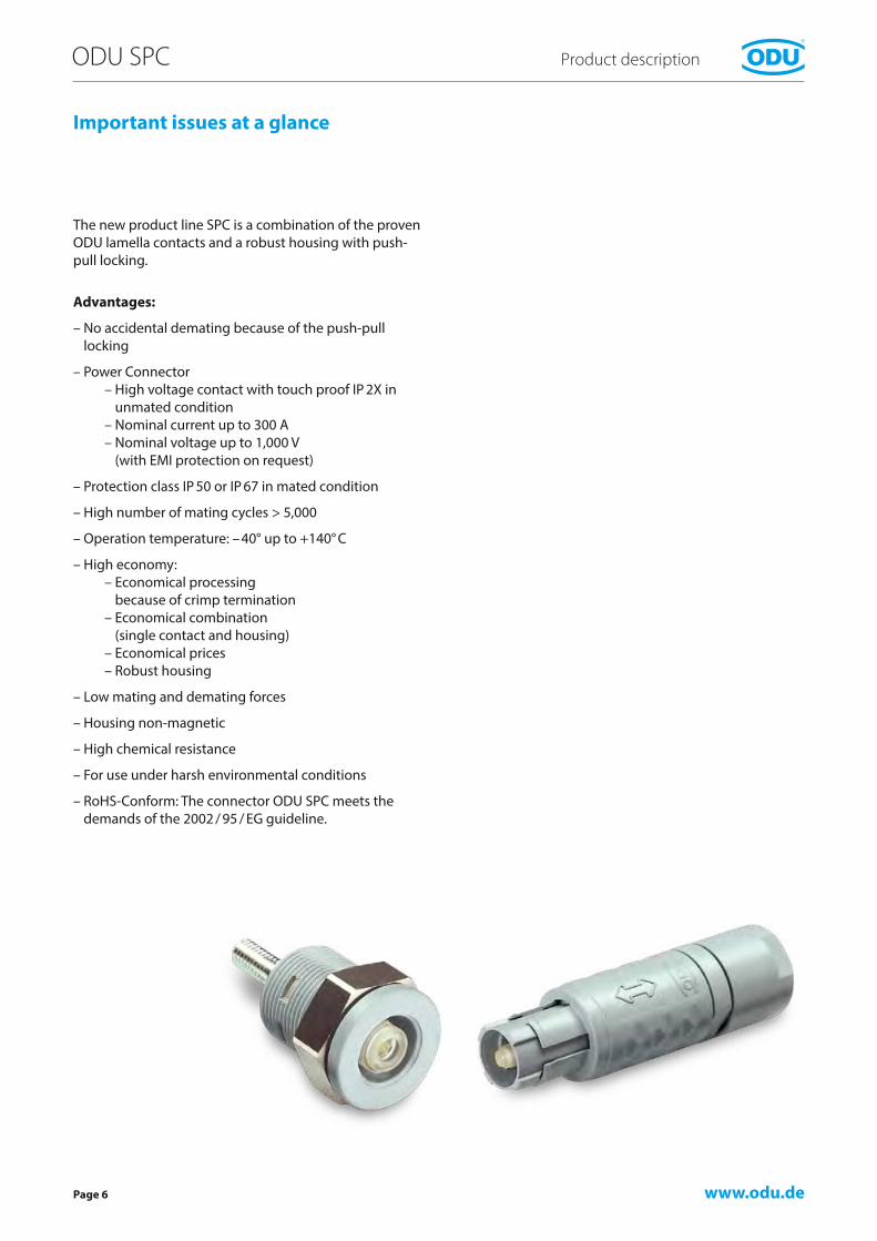
Important issues at a glance
The new product line SPC is a combination of the proven ODU lamella contacts and a robust housing with push-pull locking.
Advantages:
– No accidental demating because of the push-pull locking
– Power Connector – High voltage contact with touch proof IP 2X in unmated condition – Nominal current up to 300 A – Nominal voltage up to 1,000 V (with EMI protection on request)
– Protection class IP 50 or IP 67 in mated condition
– High number of mating cycles > 5,000
– Operation temperature: –40° up to +140° C
– High economy: – Economical processing because of crimp termination – Economical combination (single contact and housing) – Economical prices – Robust housing
– Low mating and demating forces
– Housing non-magnetic
– High chemical resistance
– For use under harsh environmental conditions
– RoHS-Conform: The connector ODU SPC meets the demands of the 2002 / 95 / EG guideline.

www.odu.de
ODU SPC
Page 7
Product description
Push-pull locking principle
Pulling on the cable or on the back nut causes the locking fingers to grip tighter into the groove inside receptacle. A separation is virtually impossible.
Pulling on the outer plug housing disengages the locking fingers from the receptacle groove and the connector separates easily.
The advantages of push-pull locking – Quick and easy mating and locking – Quick and easy separating – Easy blind mating in difficult-to-reach places – Less space required – Definite and secure locking condition.

www.odu.dePage 8
ODU SPC Product description
Contact technology: ODU lamella contact
The lamella contact consists of a stamped contact band with lamellas which is mounted into a turned carrier. The individual lamella ridges result in a multitude of contact points that guarantee a high level of contact stability and ensure optimal conductive characteristics. The ad-justed contact force ensures low insertion and removal forces, and consequently a long service life with few signs of wear.
If the contact diameter is 4 mm, for example, the ODU lamella contact results in a total of 18 contact points. Larger diameters correspondingly produce more contact points.
Features / Advantages
– Low contact resistance – Low fall of voltage – High number of contact points – High number of mating cycles / long product lifetime – High ampacity – Constant power transmission – No loss of power.
Socket
Unmated
Carrier Lamella
A
A
Pin
MatedView A–A
www.odu.de
ODU SPC
Page 9
Product description
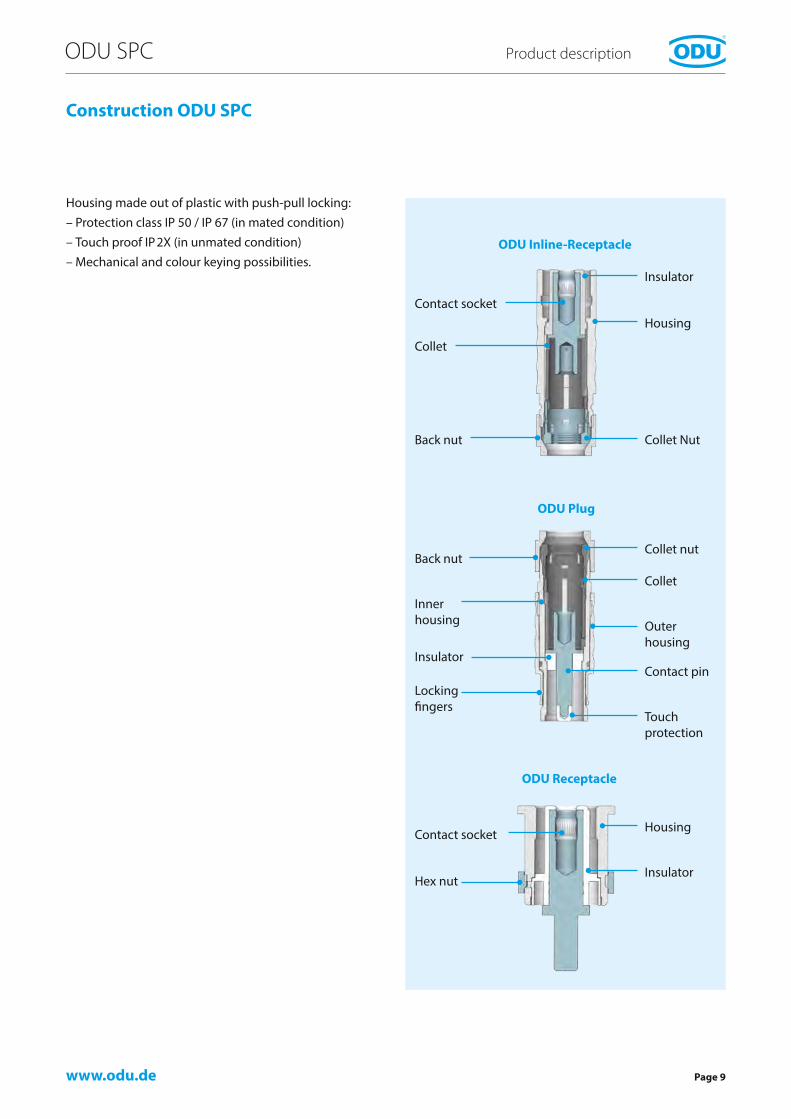
Construction ODU SPC
Housing made out of plastic with push-pull locking: – Protection class IP 50 / IP 67 (in mated condition) – Touch proof IP2X (in unmated condition) – Mechanical and colour keying possibilities.
Collet nut
Collet
Locking fingers
Touch protection
Contact pin
HousingContact socket
Insulator
Insulator
Contact socketHousing
Collet
Collet Nut
Back nut
Inner housing Outer
housing
Back nut
InsulatorHex nut
ODU Plug
ODU Inline-Receptacle
ODU Receptacle

www.odu.dePage 10
ODU SPC Product description
Everything from one source – ODU the system supplier
Every connection also needs its cable. Make no compro-mises here when it comes to the quality of the complete connection system. ODU gives you the complete system solution from one source, with no intermediary suppliers.
Cable assembly is a very complex subject. It requires equal measures of expertise in the areas of connectors, cables and assembly. ODU meets all these requirements in full.
Benefits for the customer: – ODU handles the complete processing, from procuring the cable to procuring connectors from other companies, and assembly up to individual extrusion or potting – No one knows our products better then we – no one knows how our products have to be processed better then we do – Close cooperation and experience with well-known cable manufacturers – Assembly of all standard lines, as well as special lines such as hybrid cable – Assembly of overmolded cable crossovers – 100 % inspection – systems can be used at the customer without testing. – Various potting options for water-tight or vacuum-tight system – UL approval (File: E333666) for cable assembly – Production in cleanroom acc. EN ISO 14644-1 possible – Production acc. medical certification ISO 13485 : 2003 + AC : 2007 possible – State-of-the-art production facilities in Mühldorf (Germany), Shanghai (China), Camarillo (USA) and Sibiu (Romania).

www.odu.de
1 2 3 4 5 6 7 8 9 10 11 12 13 14 15 16 17 18 19
P – A –
1 2 3 4 5 6 7 8 9 10 11 12 13 14 15 16 17 18 19
S 1 1 P 2 G – U 0 A C A K 0 – 3 7 0 0
ODU SPC
Page 11
Product description
The part number key
No. Description Coding
1
Type
S = Plug G = Receptacle K = In-line receptacle
2 Style 1 – 9 and A – Z
3 Size 1, 2, 34 SPC P5 Coding6 Housing material / colour
8 Insulator material9 Colour coding*
10 Surface11 Termination12 Type A13 14
Termination cross section (2 positions)
16 17
Collet system (2 positions)
18 19
Cable bend relief (2 positions)
1 = Plug 2 = Style 1, IP 50 with standard back nut 3 = Size 1 4 = Product series SPC 5 = Coding 2 6 = Plastic housing in grey 8 = Insulator material PSU/PPSU 9 = No colour coding 10 = Surface Ag 11 = Crimp termination 12 = Plastic housing – without EMI protection 13/14 = Cross section 4.0 mm² 16/17 = Collet system for cable diameter > 2.5 – 3.7 mm 18/19 = Without cable bend relief
Example
* Size 1 – 3: Colour Coding with cable bend relief


www.odu.de
∅ 18∅ 15∅ 12
Page 14
ODU SPC Without protection class
Technical data
Outside diameter – Plug
Dimensions in mm
Mechanical and electrical data Size / Contact diameter
1∅ 3.0 mm
2∅ 4.0 mm
3∅ 5.0 mm
Mechanical data:
Insertion force 10 N 13 N 16 N
Withdrawal force 9 N 12 N 15 N
Draw out strength1 > 75 N > 80 N > 85 N
Electrical data:
Nominal current 2 32 A 42 A 53A
Max. continuous current 2 55 A 70 A 91 A
Surge current (period 10 ms) 5 kA 8 kA 12 kA
Rated voltage (= nominal voltage) 3 1,000 V 1,000 V 1,000 V
Test voltage 4,260 V 4,260V 4,260 V
Contact resistance 350 µΩ 300 µΩ 250 µΩ
1 Connector can be used again after a accidentally demating. The datas are for the standard housing – without insert.2 Derating measurement procedure see page 42 / 43. Data derived from the derating curve.3 Tested with standing voltage with 50 Hz acc. DIN EN 61984 (VDE 0627) : 2009-11 / EN 61984 : 2009.
Available housing sizes
Size 1 Size 2 Size 3

www.odu.de
ODU SPC
Page 15
ODU SPC with push-pull locking protection class IP 50 and IP 67 *
*Explanation of protection classes see page 47.
www.odu.de
L1 L1
SW-B SW-B
SW-A SW-AL2 L2
∅ D
∅ D
Page 16
ODU SPC Protection class IP 50 and IP 67
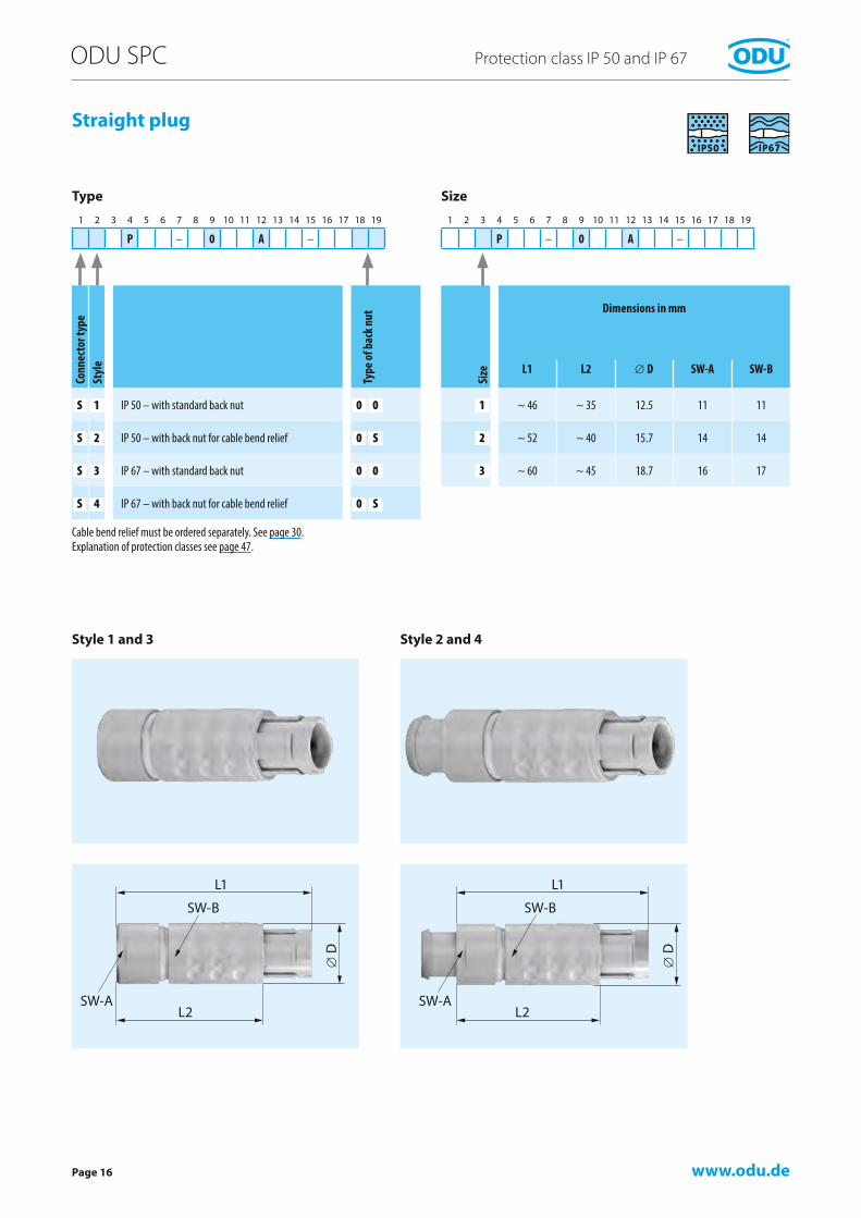
Straight plug
Type
Style 1 and 3
Size
Style 2 and 4
Cable bend relief must be ordered separately. See page 30.Explanation of protection classes see page 47.
1 2 3 4 5 6 7 8 9 10 11 12 13 14 15 16 17 18 19
P – 0 A –
1 2 3 4 5 6 7 8 9 10 11 12 13 14 15 16 17 18 19
P – 0 A –
Conn
ecto
r typ
eSt
yle
Type
of b
ack n
ut
S 1 IP 50 – with standard back nut 0 0
S 2 IP 50 – with back nut for cable bend relief 0 S
S 3 IP 67 – with standard back nut 0 0
S 4 IP 67 – with back nut for cable bend relief 0 S
Size
Dimensions in mm
L1 L2 ∅ D SW-A SW-B
1 ~ 46 ~ 35 12.5 11 11
2 ~ 52 ~ 40 15.7 14 14
3 ~ 60 ~ 45 18.7 16 17
www.odu.de
LC
M2
M3
∅ DSW
ODU SPC
Page 17
Protection class IP 50 and IP 67
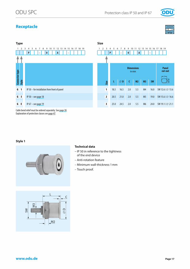
Receptacle
Type Size
Cable bend relief must be ordered separately. See page 30.Explanation of protection classes see page 47.
1 2 3 4 5 6 7 8 9 10 11 12 13 14 15 16 17 18 19
P – 0 A –
1 2 3 4 5 6 7 8 9 10 11 12 13 14 15 16 17 18 19
P – 0 A –
Conn
ecto
r typ
eSt
yle
G 1 IP 50 – for installation from front of panel
G 5 IP 50 – see page 18
G E IP 67 – see page 19Si
ze
Dimensions in mm
Panel cut-out
L ∅ D C M2 M3 SW
1 18.5 16.5 2.0 5.5 M4 16.0 SW 12.6 / ∅ 13.6
2 20.5 21.0 2.0 5.5 M5 19.0 SW 15.6 / ∅ 16.6
3 25.0 24.5 2.0 5.5 M6 24.0 SW 19.1 / ∅ 21.1
Style 1
Technical data – IP 50 in reference to the tightness of the end device – Anti-rotation feature – Minimum wall-thickness 1 mm – Touch proof.

www.odu.de
LM1
SWM2
∅ D
SW
M3
Page 18
ODU SPC Protection class IP 50 and IP 67
Receptacle
Type Size
1 2 3 4 5 6 7 8 9 10 11 12 13 14 15 16 17 18 19
P – 0 A –
1 2 3 4 5 6 7 8 9 10 11 12 13 14 15 16 17 18 19
P – 0 A –
Conn
ecto
r typ
eSt
yle
G 1 IP 50 – see page 17
G 5 IP 50 – with continuous thread, installation from rear or front of panel, optimal distance adjustment
G E IP 67 – see page 19Si
ze
Dimensions in mm Panel cut-out
L ∅ D M1 M2 M3 SW
1 18.5 19.0 5.0 5.5 M4 16.0 SW 12.6 / ∅ 13.6
2 20.5 21.5 5.0 5.5 M5 19.0 SW 15.6 / ∅ 16.6
3 25.0 28.0 5.0 5.5 M6 24.0 SW 19.1 / ∅ 21.1
Style 5
Technical data – IP 50 in reference to the tightness of the end device – Anti-rotation feature – Minimum wall-thickness 1 mm – Touch proof.
Cable bend relief must be ordered separately. See page 30.Explanation of protection classes see page 47.

www.odu.de
M1L
M2
∅ DSW
M3
ODU SPC
Page 19
Protection class IP 50 and IP 67
Receptacle
Type Size
Explanation of protection classes see page 47.
1 2 3 4 5 6 7 8 9 10 11 12 13 14 15 16 17 18 19
P – 0 A – 0 0
1 2 3 4 5 6 7 8 9 10 11 12 13 14 15 16 17 18 19
P – 0 A –
Conn
ecto
r typ
eSt
yle
G 1 IP 50 – see page 17
G 5 IP 50 – see page 18
G E IP 67 – for installation from front of panelSi
ze
Dimensions in mm Panel cut-out
L ∅ D C M1 M2 M3 SW
1 22.0 18.5 ~6.0 ~6.0 5.5 M4 16.0 SW 12.6 / ∅ 13.6
2 24.0 22.5 ~6.0 ~6.0 5.5 M5 19.0 SW 15.6 / ∅ 16.6
3 28.5 26.5 ~6.0 ~6.0 5.5 M6 24.0 SW 19.1 / ∅ 21.1
Style E
Technical data – IP 67 in mated condition – IP 50 in unmated condition and in reference to the tightness of the end device – Anti-rotation feature – Minimum wall-thickness 1 mm – Touch proof.

www.odu.de
L1 L1
SW-A SW-B SW-A SW-B
∅ D
∅ D
Page 20
ODU SPC Protection class IP 50 and IP 67
In-line receptacle
Style 1 Style 2
Type Size
Cable bend relief must be ordered separately. See page 30.Explanation of protection classes see page 47.Note: Standard colour is black – other colours on request!
1 2 3 4 5 6 7 8 9 10 11 12 13 14 15 16 17 18 19
P S – 0 A –
1 2 3 4 5 6 7 8 9 10 11 12 13 14 15 16 17 18 19
P S – 0 A –
Conn
ecto
r typ
eSt
yle
Type
of b
ack n
ut
K 1 IP 50 – with standard back nut 0 0
K 2 IP 50 – with back nut for cable bend relief 0 S
K 3 IP 67 – see page 21 0 0
K 4 IP 67 – see page 21 0 S
Size
Dimensions in mm
L ∅ D SW-A SW-B
1 ~ 46 12.5 11 11
2 ~ 52 15.7 14 14
3 ~ 60 18.7 16 17

www.odu.de
L1 L1
SW-A SW-ASW-B SW-B
∅ D
∅ D
ODU SPC
Page 21
Protection class IP 50 and IP 67
In-line receptacle
Style 3 Style 4
Type Size
1 2 3 4 5 6 7 8 9 10 11 12 13 14 15 16 17 18 19
P S – 0 A –
1 2 3 4 5 6 7 8 9 10 11 12 13 14 15 16 17 18 19
P S – 0 A –
Size
Dimensions in mm
L1 ∅ D SW-A SW-B
1 ~ 46 16.2 11 11
2 ~ 52 19.8 14 14
3 ~ 60 23.0 16 17
Conn
ecto
r typ
eSt
yle
Type
of b
ack n
ut
K 1 IP 50 – see page 20 0 0
K 2 IP 50 – see page 20 0 S
K 3 IP 67 – with standard back nut 0 0
K 4 IP 67 – with back nut for cable bend relief 0 S
Cable bend relief must be ordered separately. See page 30.Explanation of protection classes see page 47.Note: Standard colour is black – other colours on request!

www.odu.dePage 22
ODU SPC Protection class IP 50 and IP 67
Coding
Insulator material
Housing material
Contact surface
1 2 3 4 5 6 7 8 9 10 11 12 13 14 15 16 17 18 19
P – 0 A –
1 2 3 4 5 6 7 8 9 10 11 12 13 14 15 16 17 18 19
P – 0 A –
1 2 3 4 5 6 7 8 9 10 11 12 13 14 15 16 17 18 19
P – 0 A –
1 2 3 4 5 6 7 8 9 10 11 12 13 14 15 16 17 18 19
P – 0 A –
Codi
ng
Receptacle front view Size
1 2 3
1
2
9
Hous
ing
mat
eria
l Housing material
G Plastic, grey (similar RAL 7035)
S Plastic, black (similar RAL 9004)
W Plastic, white (similar RAL 9002), on request
Cont
act s
urfa
ce
Contact surface
A Galv. Ag (standard)
B Galv. Au (updated resistance)
Mat
eria
l ins
ulat
ion
body
Material
U PSU / PPSU (autoclaveable)
Explanation of protection classes see page 47

www.odu.de
ODU SPC
Page 23
Protection class IP 50 and IP 67
Termination Cross section
1 2 3 4 5 6 7 8 9 10 11 12 13 14 15 16 17 18 19
P – 0 A –
1 2 3 4 5 6 7 8 9 10 11 12 13 14 15 16 17 18 19
P – 0 A –Te
rmin
atio
n
Connector type
Plug Receptacle In-line receptacle
Crimp C Standard
Standard
Solder L
Screw S Standard
Cross section
Cros
s sec
tion
Size
mm² AWG 1 2 3
4.0 – K 0
6.0 10 L 0
10.0 8 N 0
Biggest possible cross section is stated. This cross-section depends on the cable diameter under consideration of the collet system. Other cross sections on request!
Explanation of protection classes see page 47.
Termination cross-section:The indicated cross-sections correspond to a flexible conductor design in accordance with EN 60228:2005 class 5 or to a flexible conductor design (7/19 strands) in accordance with AWG (ASTM B258-02).

www.odu.dePage 24
ODU SPC Protection class IP 50 and IP 67
1 2 3 4 5 6 7 8 9 10 11 12 13 14 15 16 17 18 19
P – 0 A
Cable diameter Size
Colle
t sys
tem
mm 1 2 3
> 1.5 – 2.5 2 5
> 2.5 – 3.7 3 7
> 3.1 – 4.5 4 5
> 3.7 – 4.9 4 9
> 4.6 – 6.0 6 0
> 4.9 – 6.0 6 0
> 6.1 – 7.5 7 5
> 7.6 – 9.0 9 0
> 9.1 – 10.5 0 2
Anti-rotation pin
Collet nut
Cable diameter
Collet system
www.odu.dePage 26
ODU SPC Special solutions
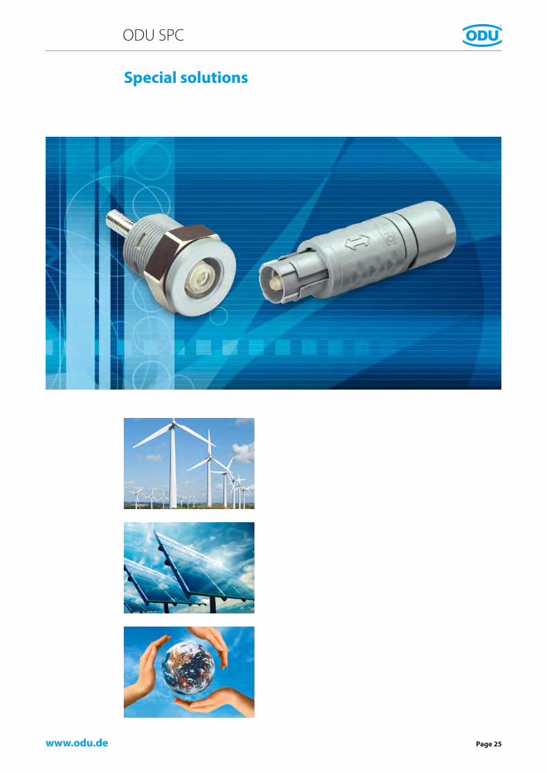
Special solutions
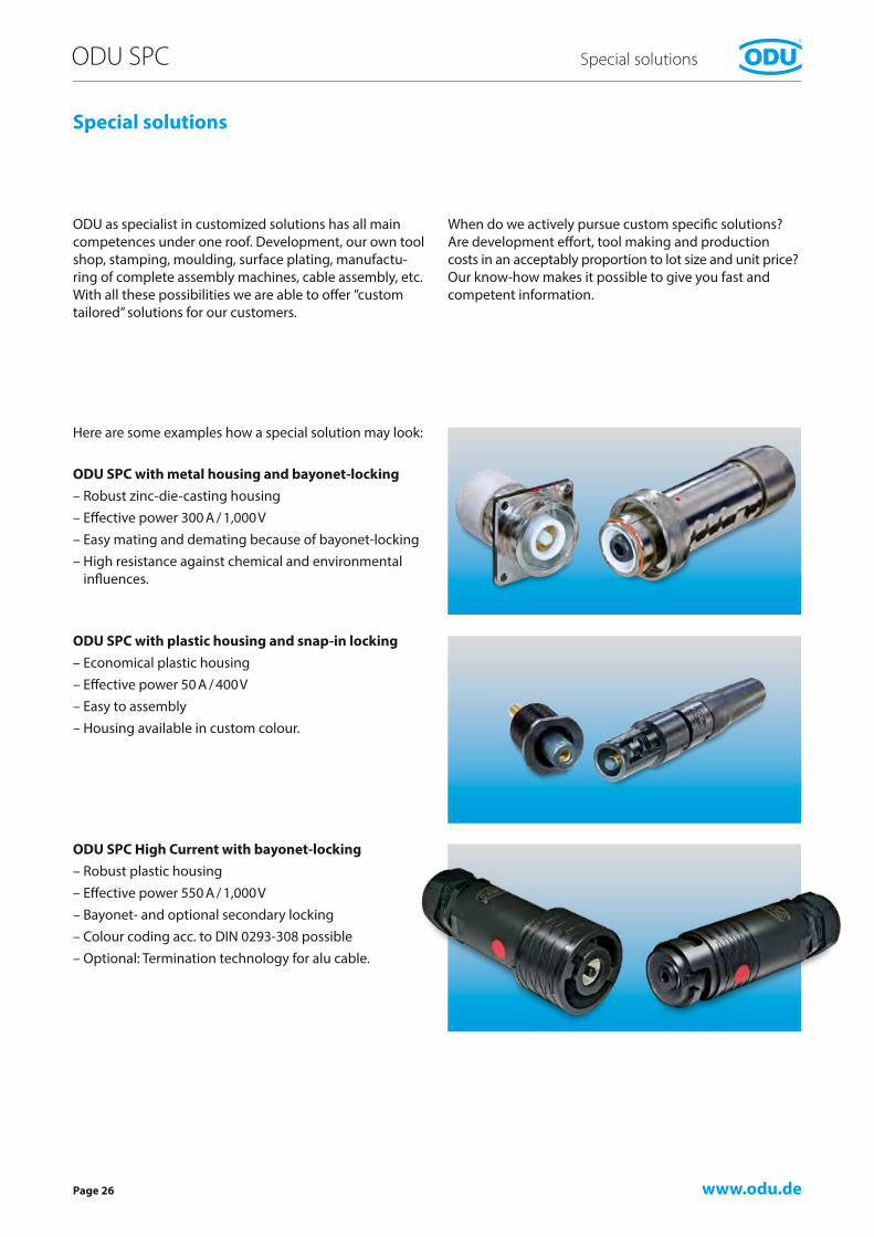
ODU as specialist in customized solutions has all main competences under one roof. Development, our own tool shop, stamping, moulding, surface plating, manufactu-ring of complete assembly machines, cable assembly, etc. With all these possibilities we are able to offer ”custom tailored” solutions for our customers.
When do we actively pursue custom specific solutions? Are development effort, tool making and production costs in an acceptably proportion to lot size and unit price?Our know-how makes it possible to give you fast and competent information.
Here are some examples how a special solution may look:
ODU SPC with metal housing and bayonet-locking – Robust zinc-die-casting housing – Effective power 300 A / 1,000 V – Easy mating and demating because of bayonet-locking – High resistance against chemical and environmental influences.
ODU SPC with plastic housing and snap-in locking – Economical plastic housing – Effective power 50 A / 400 V – Easy to assembly – Housing available in custom colour.
ODU SPC High Current with bayonet-locking – Robust plastic housing – Effective power 550 A / 1,000 V – Bayonet- and optional secondary locking – Colour coding acc. to DIN 0293-308 possible – Optional: Termination technology for alu cable.

www.odu.de
ODU SPC
Page 27
Special solutions
Metalized inner housing
ODU SPC series 329 – Current up to 400 A – Voltage up to 380 V – Robust housing – Bajonett locking.
ODU SPC with EMI ProtectionWith metalized inner housing.


www.odu.de
ODU SPC
Page 29
Accessories, Tools and termination technology Assembly Instructions

www.odu.dePage 30
ODU SPC Accessories
Silicone cable bend relief
Colour code Colour RAL-Nr.similar
202 Red 3020
203 White 9010
204 Yellow 1016
205 Green 6029
206 Blue 5002
207 Grey 7005
208 Black 9005
Because of different raw materials the colours may slightly different from RAL numbers.
Temperature range:Silicone: –50° C bis +200° C,Short-term up to +230° C
Autoclaveable
Size Part number Dim. L
Cable outer dimension
mm
Min. mm
Max. mm
1
701 023 ... 965 025 30 > 2.5 3.0
701 023 ... 965 030 30 > 3.0 3.5
701 023 ... 965 035 30 > 3.5 4.0
701 023 ... 965 040 30 > 4.0 5.0
701 023 ... 965 050 30 > 5.0 6.0
2
702 023 ... 965 025 36 >2.5 3.0
702 023 ... 965 030 36 > 3.0 3.5
702 023 ... 965 035 36 > 3.5 4.0
702 023 ... 965 040 36 > 4.0 5.0
702 023 ... 965 050 36 > 5.0 6.0
702 023 ... 965 060 36 > 6.0 7.0
702 023 ... 965 070 36 > 7.0 8.0
702 023 ... 965 080 36 > 8.0 9.0
3
703 023 ... 965 040 42 > 4.0 5.0
703 023 ... 965 050 42 > 5.0 6.0
703 023 ... 965 060 42 > 6.0 7.0
703 023 ... 965 070 42 > 7.0 8.0
703 023 ... 965 080 42 > 8.0 9.0
703 023 ... 965 090 42 > 9.0 10.0
703 023 ... 965 100 42 > 10.0 10.5

www.odu.de
A
D
BC
∅B
∅ E
A
D
BC
∅B
ODU SPC
Page 31
Accessories
Protective covers Fasten with loop – style 1 Fasten with solder lug – style 2
Size
Part number Dimensions in mm
A B C D ∅ B ∅ E
1 K01 097 006 933 … 7.8 18.80 15.1 75 17 10
2 K02 097 006 933 … 8.1 19.05 15.1 85 20 13
3 K03 097 006 933 … 10.3 19.70 16.1 100 25 16
Size
Part number Dimensions in mm
A B C D ∅ B
1 K01 097 006 933 … 7.8 18.80 15.1 75 17
2 K02 097 006 933 … 8.1 19.05 15.1 85 20
3 K03 097 006 933 … 10.3 19.70 16.0 100 25
Protection class IP 50 Protection class IP 67 with receptacle style E
Protection class IP 50 Protection class IP 67 with receptacle style E
Code Material lanyard Colour003 Polyamid White008 Polyamid Black103 Stainless steel White108 Stainless steel Black
Code Material lanyard Colour203 Polyamid White208 Polyamid Black303 Stainless steel White308 Stainless steel Black
Please register desired colour of cover and lanyard material.
Please register desired colour of cover and lanyard material.
Style 1 Style 2
∅ 3.2
www.odu.dePage 32
ODU SPC Accessories
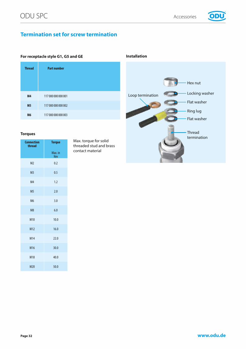
Termination set for screw termination
Torques
Installation
Connection thread
Torque
Max. in Nm
M2 0.2
M3 0.5
M4 1.2
M5 2.0
M6 3.0
M8 6.0
M10 10.0
M12 16.0
M14 22.0
M16 30.0
M18 40.0
M20 50.0
Max. torque for solid threaded stud and brass contact material
Thread Part number
M4 117 000 000 000 001
M5 117 000 000 000 002
M6 117 000 000 000 003
For receptacle style G1, G5 and GE
Locking washer
Flat washer
Flat washer
Thread termination
Ring lug
Hex nut
Loop termination

www.odu.dePage 34
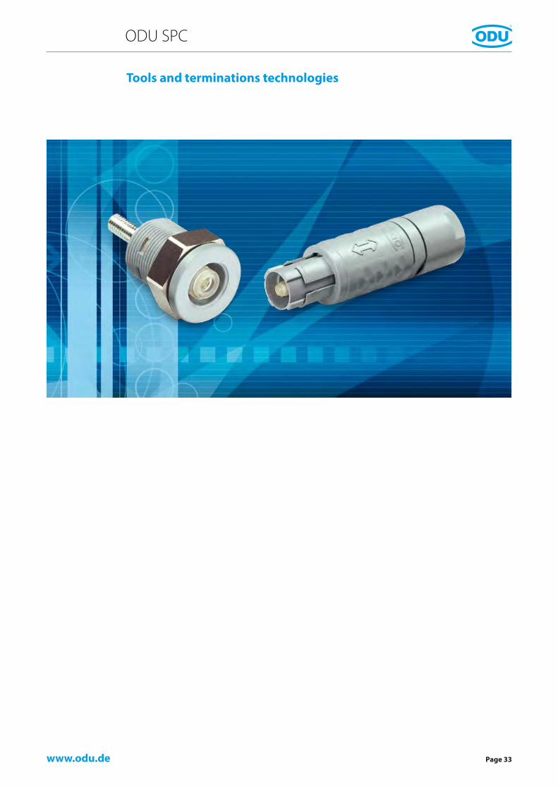
ODU SPC Tools and terminations
The three following termination technologies are possible for the ODU single contacts:
– Soldering – Screwing – Crimping
Solder termination
Soldering uses a melted added metal (solder), whose melting temperature is less than that of the base metals to be connected, in order to connect two metallic materi-als. In contrast to crimping, the wire to be soldered can also be considerably smaller than the intended solder hole. Please note: avoid undue temperature increases in sockets.
Screw termination
This method of terminating cables is usually done using cable lugs with serrated washers, flat washers and nuts. Washers and nuts are included in the delivery as standard (you will find corresponding assembly sets on page 32).
Termination technologies
Crimp termination
The processing of contacts by crimping in order to pro-duce connection lines results in a permanent, corrosion-free and securely contacted connection. Even those who are not experts can produce this time-saving termination.
The cold pressing operation (crimping) compresses the conductor and contact material at the pressing points to the extent that a gas-tight connection results that is tight with respect to the conductor material.
Crimping is possible on the smallest cross-sections as well as on large ones. The 8-point crimpers are advantageously chosen for smaller cross-sections (0.5 – 2.5 mm²) while hexagonal crimpers are chosen for the larger cross-sec-tions. The crimping’s width across corners is no larger than the original diameter. This process does not damage the line’s insulation, which can be run up to the contact end.
For flawless crimping, it is absolutely essential that the bore diameter be matched exactly to the cable. Flawless crimping of our contacts can only be guaranteed when the crimping tools recommended by ODU are used. In order to advise you, we will need to know your cable type and the cable cross-section – a sample with datasheet is particularly helpful.
Cross-section of a hexagonal crimping.

www.odu.de
ODU SPC
Page 35
Tools and terminations
The crimping tools and the associated crimping inserts are designed for the forces necessary for the pressing operation, and are provided with a safeguard to prevent the crimper from opening prematurely.
Opening is only possible after the pressing has been completed with the necessary pressure.
Tools
Hexagonal crimping tool for cross-sections 4.0 mm² and 6.0 mm².Order no. 080.000.062.000.000
Profile 3: 4 mm²Profile 4: 6 mm²
Hydraulic hexagonal crimping toolfor cross-section 10.0 mm².Crimp tong: Order no. 080.000.026.000.000Crimp insert: Order no. 080.000.026.110.000

www.odu.de
L
B
SW
b
Page 36
ODU SPC Tools and terminations
Spanner wrench
Part number Dimensions in mm
SW t B L b
598.700.001.003.000 12 2.5 24.5 115 10.0
598.700.001.004.000 13 2.5 30.5 98 16.5
598.700.001.005.000 14 2.5 30.5 98 16.5
598.700.001.007.000 16 3.0 35.5 145 15.0
598.700.001.008.000 17 3.0 35.5 145 15.0
598.700.001.013.000 19 3.0 42.0 172 16.0
598.700.001.014.000 24 3.0 54.0 119 23.5
t = Thickness


www.odu.de
1
Page 38
ODU SPC Assembly instructions
Assembly instructions
Assembly of version with protection class IP 50 and IP 67
Clamping nut Collet Sleeve Contact Insulator Connector housing
1. Slide the clamping nut, collet and sleeve on to the stripped cable.
2. Crimp or solder the wire to the contact.
3. Slide the insulator on to the contact.
4. First slide the sleeve up to the contact.
Recommended adhesive: Scotchweld, ODU order no. 890.204.000.030.025Recommended cleaning agent: Isopropyl alcoholIf adhesives that have not been released are used, cracks may appear after some time. Use only the specified adhesive.
5. Slide the sleeve and collet into the connector housing (observe the position of the guide in the connector housing).
6. Screw the clamping nut on to the assembled con nector, hold it against the surface (1) and use the ODU open-end wrench (see page 36) to tighten it. If necessary, secure the screw thread with adhesive.
www.odu.de
A
ODU SPC
Page 39
Assembly instructions
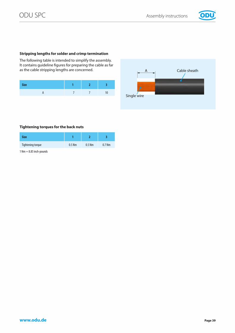
Size 1 2 3
Tightening torque 0.5 Nm 0.5 Nm 0.7 Nm
Tightening torques for the back nuts
Stripping lengths for solder and crimp termination
1 Nm = 8.85 inch-pounds
The following table is intended to simplify the assembly.It contains guideline figures for preparing the cable as far as the cable stripping lengths are concerned.
Size 1 2 3
A 7 7 10Single wire
Cable sheath


∆t3
∆t2
∆t1
l3
l2
l1
t3 t2 t1
www.odu.dePage 42
ODU SPC Technical information
Basic principles of current carrying capacityDerating measurement procedure (DIN EN 60512-5-2:2002)
A connector’s current carrying capacity is determined by measurement. The self-heating and ambient temperature are taken into account when determining the current carrying capacity, which is limited by the thermal proper-ties of the contact materials used; the upper limit tem-perature of these materials should not be exceeded.
The relationship between current, the temperature in-crease caused as a result of the power dissipation at the contact resistor, and the ambient temperature is depicted in a curve. The curve is drawn in a linear coordinate sys-tem with the current I as the ordinate and the temperature t
as the abscissa. The upper limit temperature is shown as a vertical straight line. The corrected current carrying capacity curve (derating curve) can be derived from the basis curve. To accomplish this, the measured curve is reduced by the derating factor 0.8 in order to eliminate variances, measurement errors, or the like in the test results.
In three measurements, the self-heating (Δt) is deter-mined at different currents on at least three connectors and the points determined in this process are connected to form a parabolic basis curve.
Structure of the basis current carrying capacity curve
Ambient temperature t in °C
Upper limit temperature determined by the materials
Curr
ent
in A
110
100
90
80
70
60
50
40
30
20
10
00 10 20 30 40 50 60 70 80 90 100 110 120 130 140
www.odu.de
ODU SPC
Page 43
Technical information
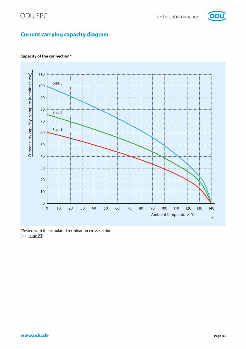
Current carrying capacity diagram
Capacity of the connection*
*Tested with the stipulated termination cross-section (see page 23).
Ambient temperature ° C
Curr
ent c
arry
cap
acity
in a
mpe
re (d
erat
ing
curv
e)
Size 3
Size 2
Size 1
www.odu.dePage 44
ODU SPC Technical information
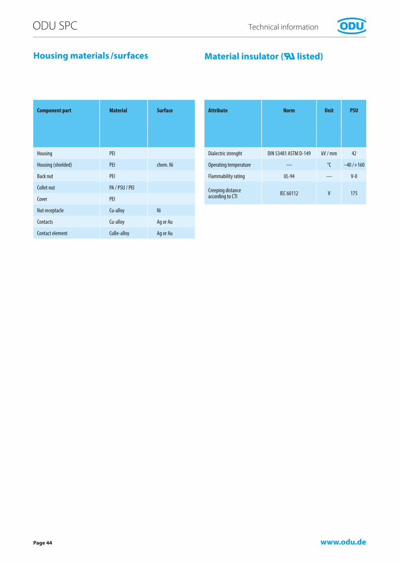
Material insulator ( listed)Housing materials /surfaces
Component part Material Surface
Housing PEI
Housing (shielded) PEI chem. Ni
Back nut PEI
Collet nut PA / PSU / PEI
Cover PEI
Nut receptacle Cu-alloy Ni
Contacts Cu-alloy Ag or Au
Contact element CuBe-alloy Ag or Au
Attribute Norm Unit PSU
Dialectric strenght DIN 53481 ASTM D-149 kV / mm 42
Operating temperature — °C –40 /+160
Flammability rating UL-94 — V-0
Creeping distance according to CTI IEC 60112 V 175
www.odu.de
ODU SPC
Page 45
Technical information
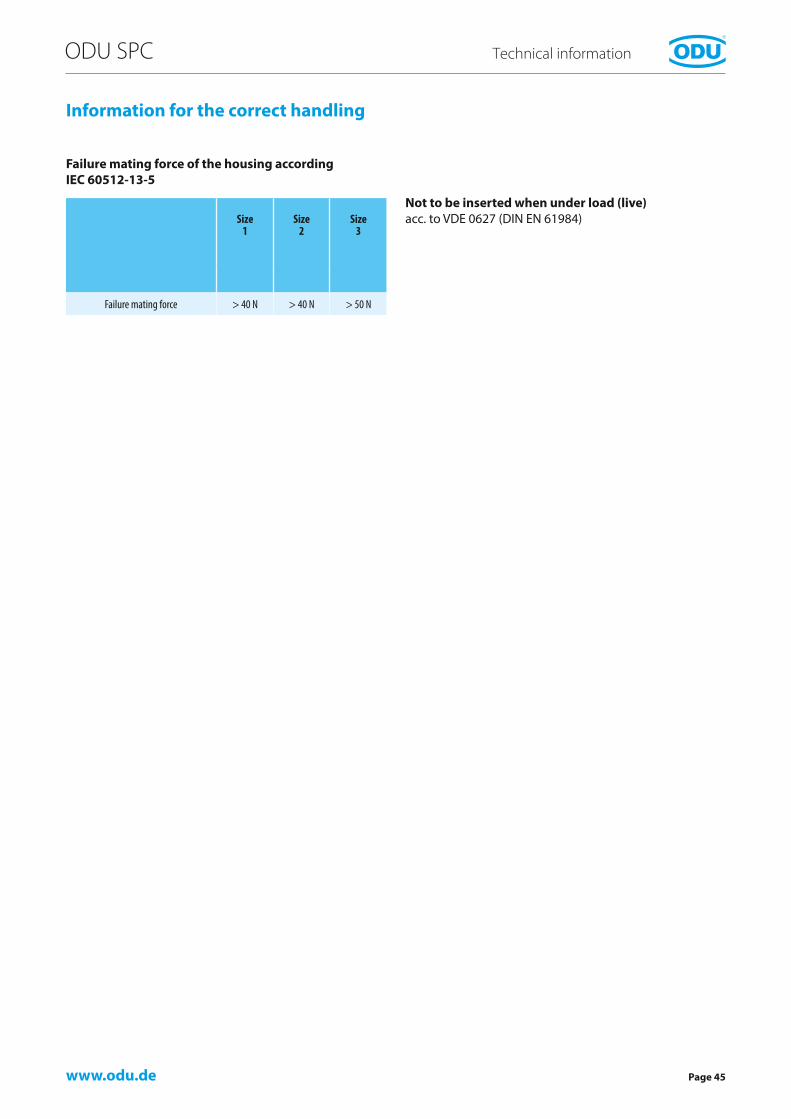
Information for the correct handling
Size 1
Size 2
Size 3
Failure mating force > 40 N > 40 N > 50 N
Not to be inserted when under load (live) acc. to VDE 0627 (DIN EN 61984)
Failure mating force of the housing according IEC 60512-13-5

www.odu.dePage 46
ODU SPC Technical information
Sterilizability
AutoclaveThe connectors in the ODU SPC series have been tested for 200 autoclave cycles according to the sterilization curve below. The standard version of ODU SPC is auto-claveable.
Gamma Radiation4 cycles à 25 k Gray
E-Beam4 cycles à 25 k Gray
For additional sterilization methods, please contact our technical team.
Sterilization curve
Ventilation
Pressure in mbar absolut
Time
0
1013
2000
3000
1. P
re-v
acuu
m
Prea
ssur
e in
crea
se
Prea
ssur
e de
crea
se
Prea
ssur
e de
crea
se
Aft
er-v
acuu
m
Dry
ing
time
Vent
ilatio
n
2. P
re-v
acuu
m
Prea
ssur
e in
crea
se
Tem
pera
ture
incr
ease
in
tran
sitio
n
Influ
ence
5 m
in. a
t 134
°C
15 m
in. a
t 121
°C
Increase of pressure Sterilization Drying

www.odu.de
ODU SPC
Page 47
Technical information
International Protecting (IP) Classes DIN EN 60529 (respectively IEC 529 / VDE 0470 T1)
The housing and the locking system of the ODU SPC protect the contacts against outside mechanical influ-ence, such as impact shocks, impuri-ties, dust, unintended contact and penetration of moisture, waster or other liquids (coolants, oils, etc.)
Protection classification is indicated with the letters IP and two numbers.
To achieve leak tightness at the cable gland, the sealing system must be adapted to the cable and the cable must be smooth, cylindrical and grooveless.
If coordination to the cable is not possible, the cable area can also be potted.
Code letters(internationalprotection)
First index figure(foreign bodiesprotection)
Second index figure(water protection)
IP 6 8
Index Degree of protection Index Degree of protection
0No protection againstaccidental contact, noprotection against intrusi-on of solid foreign bodies 0
No protection against water
1Protection against contact with any large area byhand and against largesolid foreign bodies with∅ > 50 mm
1Protection against vertical water drips
2Protection againstcontact with the fingers,protection against largesolid foreign bodies with∅ > 12 mm
2Protection against water drips (up to a 15° angle)
3Protection against tools,wires or similar objects with ∅ > 2.5 mm. Protectionagainst small foreign solidbodies with 0 > 2.5 mm
3Protection againstdiagonal water drips(up to a 60° angle)
4As 3 however ∅ > 1 mm
4Protection againstsplashed water from all directions
5Full protection againstcontact. Protectionagainst interior detrimen-tal dust deposition 5
Protection againstwater spray from all directions
6Total protection againstcontact. Protectionagainst intrusion of dust 6
Protection againsttemporary flooding
7Protection againsttemporary immersion
8Protection againstwater pressure
In accordance with DIN VDE 0470, DIN EN 60 529, IEC 529Source: ZVEI = German Association of the Electrotechnical and Electronic Industry e.V.

www.odu.dePage 48
ODU SPC Technical information
Conversions AWG – cross section (AWG = American Wire Gauge)
The AWG system describes the cross section of a wire using a gauge number for every 26 % increase in conduc-tor cross section. With larger wire diameters, the AWG gauge numbers decrease; as the wire sizes increase, the AWG gauge numbers decrease. This is only valid for solid conductors.
Most wires are made with stranded conductors. Com-pared to solid conductors stranded wires offer higher durability, higher flexibility and better performance under bending and vibration.
Stranded wires are made from wires with smaller gauge sizes (higher AWG gauge number). The AWG gauge number of the stranded wire is equal to that of a solid conductor of the same size wire. The cross section of the stranded conductor is the sum of cross sections of the single conductors. For example, a AWG-20 stranded wire of 7 AWG-28 conductors has a cross section of 0.563 mm²; an AWG-20 stranded wire with 19 AWG-32 conductors has a cross section of 0.616 mm².
Circular wire
AWG Diameter Cross section
Weight Max. resistance
Inch mm mm² kg/km Ω/km
10 (1) 0.1020 2.5900 5.2700 47.000 3.4510 (37/26) 1.1090 2.7500 4.5300 43.600 4.1312 (1) 0.0808 2.0500 3.3100 29.500 5.4512 (19/25) 0.0895 2.2500 3.0800 28.600 6.1412 (37/28) 0.0858 2.1800 2.9700 26.300 6.3614 (1) 0.0641 1.6300 2.0800 18.500 8.7914 (19/27) 0.0670 1.7000 1.9400 18.000 9.9414 (37/30) 0.0673 1.7100 1.8700 17.400 10.5016 (1) 0.0508 1.2900 1.3100 11.600 13.9416 (19/29) 0.0551 1.4000 1.2300 11.000 15.7018 (1) 0.0403 1.0200 0.8200 7.320 22.1818 (19/30) 0.0480 1.2200 0.9600 8.840 20.4020 (1) 0.0320 0.8130 0.5200 4.610 35.1020 (7/28) 0.0366 0.9300 0.5600 5.150 34.1020 (19/32) 0.0384 0.9800 0.6200 5.450 32.0022 (1) 0.0252 0.6400 0.3240 2.890 57.7022 (7/30) 0.0288 0.7310 0.3540 3.240 54.8022 (19/34) 0.0307 0.7800 0.3820 3.410 51.8024 (1) 0.0197 0.5000 0.1960 1.830 91.2024 (7/32) 0.0230 0.5850 0.2270 2.080 86.0024 (19/36) 0.0252 0.6400 0.2400 2.160 83.3026 (1) 0.1570 0.4000 0.1220 1.140 147.0026 (7/34) 0.0189 0.4800 0.1400 1.290 140.0026 (19/38) 0.0192 0.4870 0.1500 1.400 131.0028 (1) 0.0126 0.3200 0.0800 0.716 231.0028 (7/36) 0.0150 0.3810 0.0890 0.813 224.0028 (19/40) 0.0151 0.3850 0.0950 0.931 207.0030 (1) 0.0098 0.2500 0.0506 0.451 374.0030 (7/38) 0.0115 0.2930 0.0550 0.519 354.0030 (19/42) 0.0123 0.3120 0.0720 0.622 310.0032 (1) 0.0080 0.2030 0.0320 0.289 561.0032 (7/40) 0.0094 0.2400 0.0350 0.340 597.1032 (19/44) 0.0100 0.2540 0.0440 0.356 492.0034 (1) 0.0063 0.1600 0.0201 0.179 951.0034 (7/42) 0.0083 0.2110 0.0266 0.113 1,491.0036 (1) 0.0050 0.1270 0.0127 0.072 1,519.0036 (7/44) 0.0064 0.1630 0.0161 0.130 1,322.0038 (1) 0.0040 0.1000 0.0078 0.072 2,402.0040 (1) 0.0031 0.0800 0.0050 0.043 3,878.6042 (1) 0.0028 0.0700 0.0038 0.028 5,964.0044 (1) 0.0021 0.0540 0.0023 0.018 8,660.00
Conversion table AWG/mm²

www.odu.de
ODU SPC
Page 49
Technical information
Technical information / definition / terms
AutoclavabilitySee page 46.
AWGSee page 48.
Basis curveMetrologically established current carrying capac-ity curve for connectors according to the measure-ment procedure described in EN 60512-5-2:2002 depending on the permissible limit temperature of the materials.
Clearance distanceThe shortest distance, measured as a thread meas-ure, between two live metallic parts in the air.
CodingSystem of projections and grooves on mating connectors which prevent otherwise identical connectors from being mated. This is useful when several connectors of the same style are used in the same application.
Connector = ODU SPCA component that allows the connection of electri-cal conductors and that is intended to set up connections with a suitable mating component and/or to separate them. Connectors are operating materials that are not permitted to be inserted or separated when used as intended (when ener-gized). The connector consists of the connector housing and the contact elements.
Contact resistanceTotal resistance from termination to termination; the contact resistance here is considerably lower than the volume resistance. The information pro-vided refers to average values.
Creepage distancesShortest distance between live parts on the surface of insulators. All elevations and depressions in the insulator are taken into account as far as the speci-fied minimum dimensions are given.
Crimp areaThe part of a crimp barrel at which the crimp connection is achieved by pressure deformation or by reshaping the barrel around the conductor.
Crimp barrelA hollow part of a contact which accepts one or more conductors and which may be crimped through the application of a crimping tool.
Crimp connectionSee page 34.
Current carrying capacity (nominal current and max. continuous current)The information refers to sufficiently dimensioned connection cables in accordance with DIN VDE 0295 (EN 60228) in Class 5, so that this is not the source of a greater temperature increase. The specified temperature increase takes place through the contact. The information provided refers to average values.
Derating curveThe corrected current carrying capacity curve, derived from the established basis curve (0.8 × measured current). It takes into consideration production spreads as well as uncertainties in the temperature measurement and the measurement setup.
Derating measurement procedure (EN 60512-5-2)Measurement procedure for determining the current carrying capacity of connectors, taking the maximum permissible limit temperature into consideration.
Fixed connectorA connector for attachment to a rigid surface (panel).
Free connectorA connector for attachment to the free end of a wire or cable. Also called free hanging connector or in-line receptacle.
Impulse currentOne-time power pulse current with a load period of 10 ms.
Insertion or withdrawal forceForce that, without the influence of a coupling or locking device, is required for completely inserting or withdrawing pluggable components.
InsulatorNon-conductive part of a connector, for electrically and mechanically separating live parts and for protection against accidental touching.
Lower limit temperatureThe lowest permissible temperature for operating a connector or plug-in device. For ODU SPC –40° C.
LubricationThe contacts are pre-lubricated at the factory.
MaterialsSee page 44.
www.odu.dePage 50
ODU SPC Technical information
Mating cyclesMechanical operation of connectors and plug-in devices by insertion and withdrawal. One mating cycles compris-es one insertion and one withdrawal
Max. continuous currentThe metrologically determined current intensity at room temperature (approx. 20° C [70° F]) that causes the con-tact temperature to rise to the limit temperature.
Nominal single contact current loadCurrent load that can load every single contact
Nominal voltageNominal voltage characterizes a component.
Operating temperature ODU SPC–40° C to +140° C (–40° F to 285° F)
Operating voltageIs the nominal voltage of the current source intended for use with the connector. The operating voltage is not permitted to exceed the connector’s nominal voltage.
Plug appliance couplerOperating materials that are permitted to be inserted or separated during the intended use (when energized or electrically charged).
Rated current (IEC 61984)The metrologically determined current intensity that leads to an increase of 45 Kelvin in the contact tempera-ture. The current is determined according to the derating measurement procedure (EN 60512-5-2:2002) and is derived from the basis curve.
Rated voltageVoltage used when rating the connectors and when defining certain operating characteristics.
Reference voltageThe standardized voltage (VDE 0110 or EN 60664-1) for which the insulation of a connector is rated.
Solder connectionTermination technology in which a melted added metal (solder), whose melting temperature is less than that of the base materials to be connected, is used to join two metallic materials.
Termination cross-sectionThe indicated cross-sections correspond to a flexible conductor design in accordance with EN 60228:2005 class 5 or to a flexible conductor design (7/19 strands) in ac-cordance with AWG (ASTM B258-02).
Termination techniquesMethods for connecting a wire to an electro-mechanical component, e.g., solderless connection according to EN 60352, such as crimp, press-in, etc., or solder contacts.
Test voltageThe voltage that a connector withstands without flashover or arcing under specified conditions.
Upper limit temperatureHighest permissible temperature for operating a connec-tor or plug-in device. This temperature includes the self-heating and the ambient temperature. For ODU SPC 140° C (285° F).
Watertightness (EN 60529)see page 47.
WireWires may be provided with an insulation cover (electrical shielding). Cables or conductors may consist of one or more wires.
Care must be taken to assure that no person can come in contact with live conductors during installation or operation of the connectors.
ODU reserves the right to change the design and performance of any product to meet changing techni-cal developments without prior notice. ODU reserves the right to discontinue any part in this catalog with-out prior notice and without obligation to continue production after the change.
Technical information / definition / terms

www.odu.de
ODU SPC
Page 51
Technical information
Quality management
ODU has had a powerful quality management system in place for years. ODU has been successfully certified to ISO 9001 since 1994. In addition, the automotive sector of the company group is certified to ISO TS 16949. The certification process was carried out by the internati-onally active BVQI (Bureau Veritas Quality International) company.
ODU is also certified according the medical norm ISO 13485 : 2003 + AC : 2007.
Additional to this ODU ist approved to different certifica-tions: VDE, UL, UL wiring harness, SCA, VG und MIL.

www.odu.dePage 52
ODU SPC
The complete ODU product rangeThe Complete ODU Product Range
Single contacts(round or fl at)
High currentconnectors
Circular connectorswith Push-Pull locking
Modular rectangular connectors
PCB connectors
Robust connectors
Disposable Systems
Application specifi c solutions
AMC – Advanced Military Connector
Cable assembly

www.odu.de
ODU SPC
Page 53
Your Partner in Many Application AreasYour Partner in Many Application Areas
ODU stands for quality, fl exibility and reliability. This is why customers working in many application areas rely on ODU products in markets such as the following:
– Medical– Industrial– Measuring and testing– Military and security– Energy– Automotive.
MEDICAL
INDUSTRIAL
MEASURING AND TESTING
MILITARY AND SECURITY
ENERGY
AUTOMOTIVE

www.odu.dePage 55
ODU GmbH & Co. KGSales ODU SPCPregelstraße 1184453 Mühldorf a. InnGERMANY
Company:
Name:
Department:
Street:
City:
Telephone:
E-mail:
Date:
ODU SPC Summery of technical requirements.
TELEFAX-INQUIRY: +49/08631/6156-49
1. Connector application
2. Environment
3. Connector type Plug Receptacle In-Line Receptacle
4. Special version
5. Style
6. Size 1 2 3
7. Coding 1 2 9
8. Colour Grey Black White (on request)
9. Termination Solder Crimp Screw
10. Cross section ________ mm² ________ AWG
11. Cable diameter ________ mm
12. Cable bend relief (colour)
13. Protection class acc. DIN EN 60 529 IP 50 (Standard) IP 67 (watertight) Other: ________
14. Operating temperature ________ °C max ________ °C min
15. Electrical specifications:
- Operating voltage ________V AC ________ V DC
- Operating current Constant: _______ A Short-term: _______ A/_______ Seconds
16. Chemical resistance against
17. Other requirements
18. Autoclaveable Yes No
19. Required quantity
20. Production quantity
ODU SPC

www.odu.de
1 2 3 4 5 6 7 8 9 10 11 12 13 14 15 16 17 18 19
– –
1 2 3 4 5 6 7 8 9 10 11 12 13 14 15 16 17 18 19
S 1 1 P 2 G – U 0 A C A K 0 – 3 7 0 0
The part number key
Page 56
Nr. Description Codierung
1
Type
S = Plug G = Receptacle K = In-line receptacle
2 Style 1 – 9 and A – Z
3 Size 1, 2, 34 SPC P5 Coding6 Contact type / surface
8 Insulator material9 Colour coding*
10 Surface11 Termination12 Type A13 14
Termination cross section (2 positions)
16 17
Collet system (2 positions)
18 19
Cable bend relief (2 positions)
1 = Plug 2 = Style 1 IP 50 with standard back nut 3 = Size 1 4 = Product Series SPC 5 = Coding 2 6 = Plastic housing in grey 8 = Insulator material PSU/PPSU 9 = No colour coding 10 = Surface Ag 11 = Crimp termination 12 = Plastic housing – without EMI protection 13/14 = Cross section 4,0 mm² 16/17 = Collet system for cable diameter > 2.5 – 3.7 mm 18/19 = Without cable bend relief
Example
* Size 1-3: Colour Coding with cable bend relief

Please open

Stan
d: 20
14/0
1 • 17
47_K
atalo
g-SP
C_e •
Des
ign:
KO
MM
A Wer
beag
entu
r Gm
bH • w
ww.
kom
maw
eb.d
e
ODU Worldwide
Other qualifi ed representatives shown on our website:www.odu.de/sales
ODU GmbH & Co. KG
Pregelstr. 1184453 Mühldorf a. InnGermany
Phone: +49 8631 6156-0Fax: +49 8631 6156-49E-Mail: [email protected]
ODU FrancePhone: +33 1 3935-4690E-Mail: [email protected]
ODU ScandinaviaPhone: +46 176 18261E-Mail: [email protected]
ODU UKPhone: +44 1509-266-433E-Mail: [email protected]
ODU USAPhone: +1 805 4840540E-Mail: [email protected]
ODU Shanghai TradingPhone: +86 21 58347828-106E-Mail: [email protected]