of tanks main works and steps for the decommissioning d ... · 3/8 provided by japan space imaging,...
TRANSCRIPT
Storage and
handling Fuel removal
Installing
FHM*
Rubble removal
& dose reduction
Storage and
handling
Fuel debris
removal Stop leakage
Dose reduction
& Leakage
identification
Dismantling
Design & Manufacturing
of devices/ equipment
Scenario development & technology consideration
Unit 1: FY2017 Fuel removal will start (under consideration)
Unit 2: After FY2017 Fuel removal will start (under consideration)
Unit 3: FY2015 Fuel removal will start (planned)
Unit 4: 2014 Fuel removal will be completed
After FY2017
Water stoppage of PCV lower
part (under consideration)
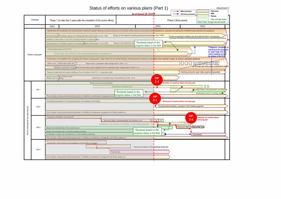
Summary of Decommissioning and Contaminated Water Management August 28, 2014 Secretariat of the Team for Countermeasures for Decommissioning and Contaminated Water Treatment
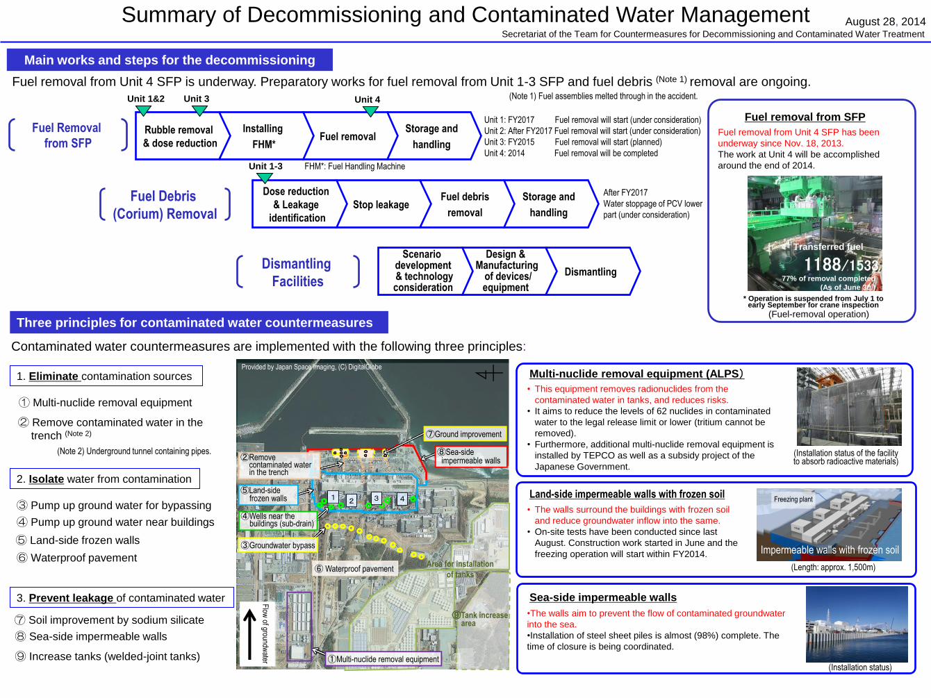
Main works and steps for the decommissioning
Fuel removal from Unit 4 SFP is underway. Preparatory works for fuel removal from Unit 1-3 SFP and fuel debris (Note 1) removal are ongoing. (Note 1) Fuel assemblies melted through in the accident.
Fuel Removal
from SFP
Fuel Debris
(Corium) Removal
Dismantling
Facilities
Fuel removal from SFP
Fuel removal from Unit 4 SFP has been
underway since Nov. 18, 2013.
The work at Unit 4 will be accomplished
around the end of 2014.
(Fuel-removal operation)
1188/1533
Transferred fuel
77% of removal completed
(As of June 30 )
* Operation is suspended from July 1 to early September for crane inspection
Unit 4 Unit 3 Unit 1&2
FHM*: Fuel Handling Machine Unit 1-3
Three principles for contaminated water countermeasures
Contaminated water countermeasures are implemented with the following three principles:
1. Eliminate contamination sources
2. Isolate water from contamination
3. Prevent leakage of contaminated water
① Multi-nuclide removal equipment
③ Pump up ground water for bypassing
④ Pump up ground water near buildings
⑤ Land-side frozen walls
⑥ Waterproof pavement
⑦ Soil improvement by sodium silicate
⑧ Sea-side impermeable walls
⑨ Increase tanks (welded-joint tanks)
Multi-nuclide removal equipment (ALPS)
• This equipment removes radionuclides from the
contaminated water in tanks, and reduces risks.
• It aims to reduce the levels of 62 nuclides in contaminated
water to the legal release limit or lower (tritium cannot be
removed).
• Furthermore, additional multi-nuclide removal equipment is
installed by TEPCO as well as a subsidy project of the
Japanese Government.
Land-side impermeable walls with frozen soil
• The walls surround the buildings with frozen soil
and reduce groundwater inflow into the same.
• On-site tests have been conducted since last
August. Construction work started in June and the
freezing operation will start within FY2014.
Sea-side impermeable walls
•The walls aim to prevent the flow of contaminated groundwater
into the sea.
•Installation of steel sheet piles is almost (98%) complete. The
time of closure is being coordinated.
(Installation status of the facility to absorb radioactive materials)
(Length: approx. 1,500m)
(Installation status)
Freezing plant
Impermeable walls with frozen soil
② Remove contaminated water in the
trench (Note 2)
(Note 2) Underground tunnel containing pipes.
Provided by Japan Space Imaging, (C) DigitalGlobe
1 2 3 4
②Remove contaminated water in the trench
⑥ Waterproof pavement
Flow
of groundwater ①Multi-nuclide removal equipment
③Groundwater bypass
④Wells near the buildings (sub-drain)
⑤Land-side frozen walls
⑦Ground improvement
⑧Sea-side impermeable walls
Area for installation
of tanks
⑨Tank increase area
2/8
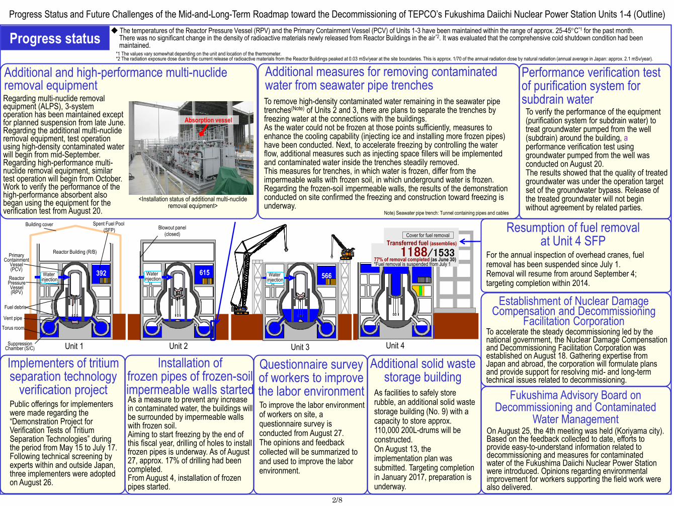
Additional and high-performance multi-nuclide removal equipment Regarding multi-nuclide removal equipment (ALPS), 3-system operation has been maintained except for planned suspension from late June. Regarding the additional multi-nuclide removal equipment, test operation using high-density contaminated water will begin from mid-September. Regarding high-performance multi-nuclide removal equipment, similar test operation will begin from October. Work to verify the performance of the high-performance absorbent also began using the equipment for the verification test from August 20.
On August 25, the 4th meeting was held (Koriyama city). Based on the feedback collected to date, efforts to provide easy-to-understand information related to decommissioning and measures for contaminated water of the Fukushima Daiichi Nuclear Power Station were introduced. Opinions regarding environmental improvement for workers supporting the field work were also delivered.
Fukushima Advisory Board on Decommissioning and Contaminated
Water Management
Performance verification test of purification system for subdrain water
To verify the performance of the equipment (purification system for subdrain water) to treat groundwater pumped from the well (subdrain) around the building, a performance verification test using groundwater pumped from the well was conducted on August 20. The results showed that the quality of treated groundwater was under the operation target set of the groundwater bypass. Release of the treated groundwater will not begin without agreement by related parties.
Note) Seawater pipe trench: Tunnel containing pipes and cables
Establishment of Nuclear Damage Compensation and Decommissioning
Facilitation Corporation
As a measure to prevent any increase in contaminated water, the buildings will be surrounded by impermeable walls with frozen soil. Aiming to start freezing by the end of this fiscal year, drilling of holes to install frozen pipes is underway. As of August 27, approx. 17% of drilling had been completed. From August 4, installation of frozen pipes started.
Installation of frozen pipes of frozen-soil impermeable walls started
<Installation status of additional multi-nuclide removal equipment>
Implementers of tritium separation technology
verification project Public offerings for implementers were made regarding the “Demonstration Project for Verification Tests of Tritium Separation Technologies” during the period from May 15 to July 17. Following technical screening by experts within and outside Japan, three implementers were adopted on August 26.
Additional measures for removing contaminated water from seawater pipe trenches To remove high-density contaminated water remaining in the seawater pipe trenches(Note) of Units 2 and 3, there are plans to separate the trenches by freezing water at the connections with the buildings. As the water could not be frozen at those points sufficiently, measures to enhance the cooling capability (injecting ice and installing more frozen pipes) have been conducted. Next, to accelerate freezing by controlling the water flow, additional measures such as injecting space fillers will be implemented and contaminated water inside the trenches steadily removed. This measures for trenches, in which water is frozen, differ from the impermeable walls with frozen soil, in which underground water is frozen. Regarding the frozen-soil impermeable walls, the results of the demonstration conducted on site confirmed the freezing and construction toward freezing is underway.
Additional solid waste storage building
As facilities to safely store rubble, an additional solid waste storage building (No. 9) with a capacity to store approx. 110,000 200L-drums will be constructed. On August 13, the implementation plan was submitted. Targeting completion in January 2017, preparation is underway.
Questionnaire survey of workers to improve the labor environment To improve the labor environment of workers on site, a questionnaire survey is conducted from August 27. The opinions and feedback collected will be summarized to and used to improve the labor environment.
To accelerate the steady decommissioning led by the national government, the Nuclear Damage Compensation and Decommissioning Facilitation Corporation was established on August 18. Gathering expertise from Japan and abroad, the corporation will formulate plans and provide support for resolving mid- and long-term technical issues related to decommissioning.
Absorption vessel
Progress status ◆ The temperatures of the Reactor Pressure Vessel (RPV) and the Primary Containment Vessel (PCV) of Units 1-3 have been maintained within the range of approx. 25-45C*1 for the past month.
There was no significant change in the density of radioactive materials newly released from Reactor Buildings in the air*2. It was evaluated that the comprehensive cold shutdown condition had been maintained.
*1 The values vary somewhat depending on the unit and location of the thermometer. *2 The radiation exposure dose due to the current release of radioactive materials from the Reactor Buildings peaked at 0.03 mSv/year at the site boundaries. This is approx. 1/70 of the annual radiation dose by natural radiation (annual average in Japan: approx. 2.1 mSv/year).
Progress Status and Future Challenges of the Mid-and-Long-Term Roadmap toward the Decommissioning of TEPCO’s Fukushima Daiichi Nuclear Power Station Units 1-4 (Outline)
Vent pipe
Torus room
Blowout panel
(closed)
392 615
構台
安全第一 福島第一 安全第一 福島第一 安全
第一
福島第一
安全第一 福島第一 安全第一 福島第一 安全第一 福島第一
クローラクレーン 1188/1533 77% of removal completed (as June 30) *Fuel removal is suspended from July 1
Cover for fuel removal
Transferred fuel (assemblies)
Unit 2 Unit 3 Unit 4 Unit 1
Water injection
Water injection
Water injection
Spent Fuel Pool
(SFP) Building cover
Reactor Building (R/B) Primary
Containment Vessel (PCV)
Reactor Pressure Vessel (RPV)
Fuel debris
Suppression Chamber (S/C)
For the annual inspection of overhead cranes, fuel removal has been suspended since July 1. Removal will resume from around September 4; targeting completion within 2014.
Resumption of fuel removal at Unit 4 SFP
566
3/8
Provided by Japan Space Imaging, (C) DigitalGlobe
Additional multi-nuclide removal
equipment
Fukushima Advisory Board on Decommissioning and Contaminated
Water Management (* Koriyama city)
Sub-drain and other treatment
facilities
Establishment of Nuclear Damage Compensation and Decommissioning
Facilitation Corporation
Questionnaire survey
of workers to improve
the labor environment
Performance verification test of purification system for subdrain water
High-performance multi-nuclide
removal equipment
Sub-drain
collection tank
Solid waste storage building
(No. 9)
Additional solid waste
storage building
Installation of frozen pipes of frozen-soil impermeable walls started
Implementers of tritium
separation technology
verification project
MP-1
MP-2
MP-3 MP-4
MP-5
MP-6
MP-7
MP-8
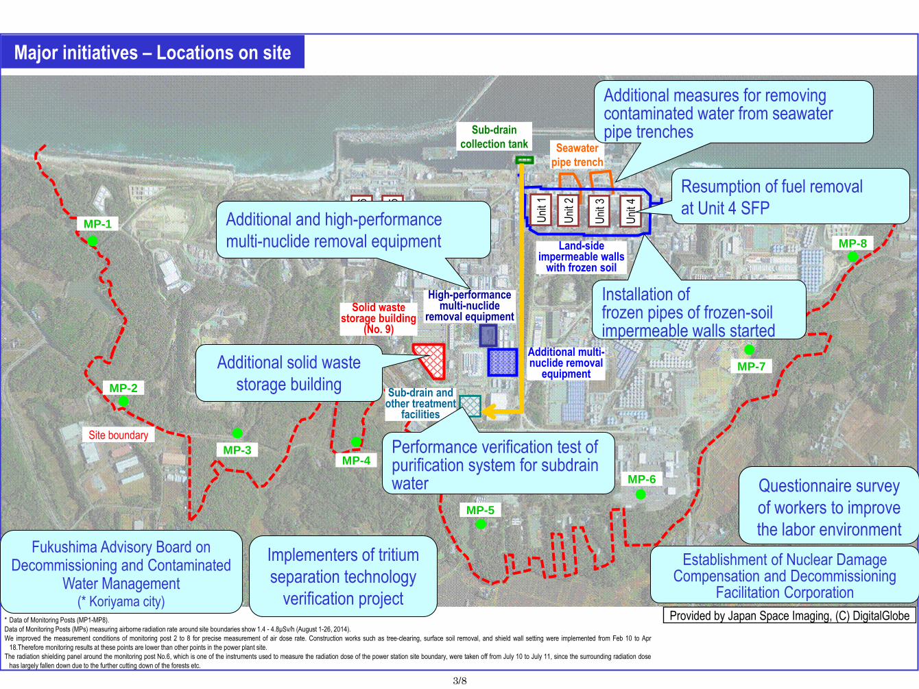
* Data of Monitoring Posts (MP1-MP8).
Data of Monitoring Posts (MPs) measuring airborne radiation rate around site boundaries show 1.4 - 4.8μSv/h (August 1-26, 2014).
We improved the measurement conditions of monitoring post 2 to 8 for precise measurement of air dose rate. Construction works such as tree-clearing, surface soil removal, and shield wall setting were implemented from Feb 10 to Apr
18.Therefore monitoring results at these points are lower than other points in the power plant site.
The radiation shielding panel around the monitoring post No.6, which is one of the instruments used to measure the radiation dose of the power station site boundary, were taken off from July 10 to July 11, since the surrounding radiation dose
has largely fallen down due to the further cutting down of the forests etc.
Major initiatives – Locations on site
Seawater
pipe trench
Additional measures for removing contaminated water from seawater pipe trenches
Land-side impermeable walls
with frozen soil
Site boundary
Uni
t 1
Uni
t 2
Uni
t 3
Uni
t 4
Uni
t 6
Uni
t 5
Additional and high-performance
multi-nuclide removal equipment
Resumption of fuel removal
at Unit 4 SFP

4/8
I. Confirmation of the reactor conditions 1. Temperatures inside the reactors
Through continuous reactor cooling by water injection, the temperatures of the Reactor Pressure Vessel (RPV) bottom and the Primary Containment Vessel (PCV) gas phase have been maintained within the range of approx. 25 to 45C for the past month, though they vary depending on the unit and location of the thermometer.
2. Release of radioactive materials from the Reactor Buildings
The density of radioactive materials newly released from Reactor Building Units 1-4 in the air measured at site boundaries was evaluated at approx. 1.3 x 10⁻⁹ Bq/cm3 for both Cs-134 and -137. The radiation exposure dose due to the release of radioactive materials was 0.03 mSv/year (equivalent to approx. 1/70 of the annual radiation dose by natural radiation (annual average in Japan: approx. 2.1 mSv/year)) at the site boundaries.
3. Other indices
There was no significant change in indices, including the pressure in the PCV and the PCV radioactivity density (Xe-135) for monitoring criticality, nor was any abnormality of cold shutdown condition or sign of criticality detected. Based on the above, it was confirmed that the comprehensive cold shutdown condition had been maintained and the reactors remained in a stabilized condition.
II. Progress status by each plan 1. Reactor cooling plan
The cold shutdown condition will be maintained by cooling the reactor by water injection and measures to complement status monitoring will continue to be implemented
Nitrogen injection test from the Unit 1 jet pump instrumentation rack ・ To prepare for cases where nitrogen cannot be injected from the existing RPV head spray line, an alternative
involving injecting nitrogen from the jet-pump instrumentation rack to the RPV was examined. The results of the soundness verification test conducted from July 28 to August 5 showed that nitrogen could be injected from that
route. The results of the stability verification test that injected 20Nm3/h from the jet pump instrumentation rack showed no change in the plant situation (August 20-27).
Replacement of the thermometer at the bottom of Unit 2 RPV ・ In April, attempts to remove and replace the thermometer installed at the bottom of the RPV, which had broken in
February 2014, failed and the operation was suspended. The estimated cause was fixing or added friction due to rust having formed. To help remove the thermometer, the effect of removal is being verified by mock-up test equipment using full-scale piping prepared for the test.
2. Accumulated water-treatment plan
To tackle the increase in accumulated water due to groundwater inflow, fundamental measures to prevent such inflow into the Reactor
Buildings will be implemented, while improving the decontamination capability of water-treatment and preparing facilities to control the
contaminated water
Operation of groundwater bypass
・ From April 9, the operation of 12 groundwater bypass pumping wells commenced sequentially to pump up
groundwater. Release was commenced from May 21 in the presence of officials from the Intergovernmental Liaison
Office for the Decommissioning and Contaminated Water Issue of the Cabinet Office. As of August 27, 27,517 m3 of
groundwater had been released. The pumped up groundwater has been temporarily stored in tanks and released
after TEPCO and the third-party organization (Japan Chemical Analysis Center) confirmed that its quality met
operational targets.
・ The groundwater level at pumping wells of the groundwater bypass is being decreased. It was confirmed that the
groundwater level at observation holes had decreased by 20-30cm compared to the level before pumping at the
groundwater bypass started (see Figure 1).
・ As the analytical results of the groundwater bypass pumping well No. 12 (sampled on August 5) showed tritium
density of 1,900Bq/L, which exceeded the operation target of 1,500Bq/L for the temporary storage tanks, pumping
from that pumping well was suspended from August 6. As the assessment results on the temporary storage tank
side based on the monitoring results (including analysis by a third-party organization) showed that the density would
not exceed the operation target, pumping resumed from August 22. Regarding the groundwater bypass pumping
well No. 12, enhanced monitoring of the tritium analytical result trends will continue.
・
0
10
20
30
40
50
60
70
80
90
100
5/26 6/5 6/15 6/25 7/5 7/15 7/25 8/4 8/14 8/24 9/3
℃
0
10
20
30
40
50
60
70
80
90
100
5/26 6/5 6/15 6/25 7/5 7/15 7/25 8/4 8/14 8/24 9/3
℃
2014 2013 2012 2011
PCV gas phase temperatures (recent quarter)
* The trend graphs show part of the temperature data measured at multiple points.
RPV bottom temperatures (recent quarter)
Reactor injection water temperature Unit 1
Unit 2
Unit 3
Unit 1
Unit 3
Reactor injection water temperature
Unit 2
Air temperature: Air temperature:
(Reference)
* The density limit of radioactive materials in the air outside the surrounding monitoring area:
[Cs-134]: 2 x 10⁻⁵ Bq/cm3 [Cs-137]: 3 x 10⁻⁵ Bq/cm3
* Dust density around the site boundaries of Fukushima Daiichi Nuclear Power Station (actual measured values):
[Cs-134]: ND (Detection limit: approx. 1 x 10⁻⁷ Bq/cm3) [Cs-137]: ND (Detection limit: approx. 2 x 10⁻⁷ Bq/cm3)
* Data of Monitoring Posts (MP1-MP8). Data of Monitoring Posts (MPs) measuring airborne radiation
rate around site boundaries show 1.4 - 4.8μSv/h (August 1-26, 2014)
To measure the variation in the airborne radiation rate of MP2-MP8 more accurately, environmental improvement (tree trimming, removal of surface soil and shielding around the MPs) has been completed.
Annual radiation dose at site boundaries by radioactive materials (cesium) released from Reactor Building Units 1-4
0
0.1
0.2
0.3
0.4
0.5
0.6
Exp
osur
e do
se (m
Sv/
year
)
1.7
Note: Different formulas and coefficients were used to evaluate the radiation dose in the facility operation plan and monthly report. The evaluation methods were integrated in September 2012. As the fuel removal from the spent fuel pool (SFP) commenced for Unit 4, the radiation exposure dose from Unit 4 was added to the items subject to evaluation since November 2013.
6.5
7.0
7.5
8.0
8.5
9.0
0 100 200 300 400 500
30日降雨量(mm)
地下水位(O
P.m)
H25.4.1~H26.5.20
H26.5.21~6.20
H26.6.21~8.17
至近(8.1~8.17)
10m-B孔
8.0
8.5
9.0
9.5
10.0
10.5
0 100 200 300 400 500
30日降雨量(mm)
地下水位(OP.m)
H25.4.1~H26.5.20
H26.5.21~6.20
H26.6.21~8.17
至近(8.1~8.17)
10m-C孔
6.5
7.0
7.5
8.0
8.5
9.0
0 100 200 300 400 500
30日降雨量(mm)
地下水位(O
P.m)
H25.4.1~H26.5.20
H26.5.21~6.20
H26.6.21~8.17
至近(8.1~8.17)
10m-A孔
:H24.11~H26.4.9 データ回帰直線(稼働前)
:H26.6.21~ データ回帰直線(本格稼働1ヶ月以降)
:H26.8.1~データ回帰直線(至近データ)
Figure 1: Water levels of groundwater bypass Observation Holes
10m-Hole A 10m-Hole B 10m-Hole C
Gro
undw
ater
leve
l (O
Pm
)
Gro
undw
ater
leve
l (O
Pm
)
Gro
undw
ater
leve
l (O
Pm
)
30-day rainfall (mm)
30-day rainfall (mm)
30-day rainfall (mm)
Apr 1, 2013 – May 20, 2014
May 21, 2014 – June 20
Jun 21, 2014 – Aug 17
Latest (Aug 1 – Aug 17)
Apr 1, 2013 – May 20, 2014
May 21, 2014 – June 20
Jun 21, 2014 – Aug 17
Latest (Aug 1 – Aug 17)
Apr 1, 2013 – May 20, 2014
May 21, 2014 – June 20
Jun 21, 2014 – Aug 17
Latest (Aug 1 – Aug 17)
: Nov 2012 – Apr 9, 2014 Data regression line (before operation)
: From Jun 21, 2014 Data regression line (one month and later after full-scale operation)
: From Aug 1 Data regression line (latest data)
5/8
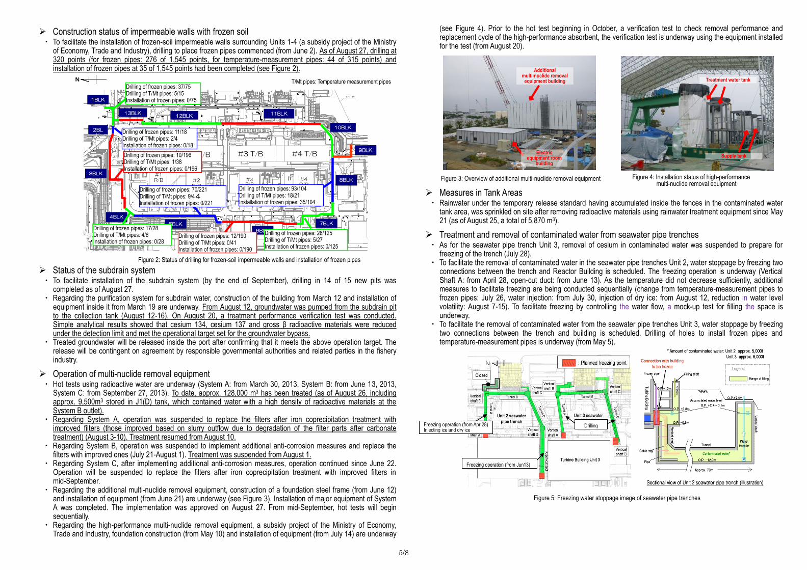
Construction status of impermeable walls with frozen soil ・ To facilitate the installation of frozen-soil impermeable walls surrounding Units 1-4 (a subsidy project of the Ministry
of Economy, Trade and Industry), drilling to place frozen pipes commenced (from June 2). As of August 27, drilling at 320 points (for frozen pipes: 276 of 1,545 points, for temperature-measurement pipes: 44 of 315 points) and installation of frozen pipes at 35 of 1,545 points had been completed (see Figure 2).
Status of the subdrain system ・ To facilitate installation of the subdrain system (by the end of September), drilling in 14 of 15 new pits was
completed as of August 27. ・ Regarding the purification system for subdrain water, construction of the building from March 12 and installation of
equipment inside it from March 19 are underway. From August 12, groundwater was pumped from the subdrain pit to the collection tank (August 12-16). On August 20, a treatment performance verification test was conducted. Simple analytical results showed that cesium 134, cesium 137 and gross β radioactive materials were reduced under the detection limit and met the operational target set for the groundwater bypass.
・ Treated groundwater will be released inside the port after confirming that it meets the above operation target. The release will be contingent on agreement by responsible governmental authorities and related parties in the fishery industry.
Operation of multi-nuclide removal equipment ・ Hot tests using radioactive water are underway (System A: from March 30, 2013, System B: from June 13, 2013,
System C: from September 27, 2013). To date, approx. 128,000 m3 has been treated (as of August 26, including approx. 9,500m3 stored in J1(D) tank, which contained water with a high density of radioactive materials at the System B outlet).
・ Regarding System A, operation was suspended to replace the filters after iron coprecipitation treatment with improved filters (those improved based on slurry outflow due to degradation of the filter parts after carbonate treatment) (August 3-10). Treatment resumed from August 10.
・ Regarding System B, operation was suspended to implement additional anti-corrosion measures and replace the filters with improved ones (July 21-August 1). Treatment was suspended from August 1.
・ Regarding System C, after implementing additional anti-corrosion measures, operation continued since June 22. Operation will be suspended to replace the filters after iron coprecipitation treatment with improved filters in mid-September.
・ Regarding the additional multi-nuclide removal equipment, construction of a foundation steel frame (from June 12) and installation of equipment (from June 21) are underway (see Figure 3). Installation of major equipment of System A was completed. The implementation was approved on August 27. From mid-September, hot tests will begin sequentially.
・ Regarding the high-performance multi-nuclide removal equipment, a subsidy project of the Ministry of Economy, Trade and Industry, foundation construction (from May 10) and installation of equipment (from July 14) are underway
(see Figure 4). Prior to the hot test beginning in October, a verification test to check removal performance and replacement cycle of the high-performance absorbent, the verification test is underway using the equipment installed for the test (from August 20).
Measures in Tank Areas ・ Rainwater under the temporary release standard having accumulated inside the fences in the contaminated water
tank area, was sprinkled on site after removing radioactive materials using rainwater treatment equipment since May 21 (as of August 25, a total of 5,870 m3).
Treatment and removal of contaminated water from seawater pipe trenches ・ As for the seawater pipe trench Unit 3, removal of cesium in contaminated water was suspended to prepare for
freezing of the trench (July 28). ・ To facilitate the removal of contaminated water in the seawater pipe trenches Unit 2, water stoppage by freezing two
connections between the trench and Reactor Building is scheduled. The freezing operation is underway (Vertical Shaft A: from April 28, open-cut duct: from June 13). As the temperature did not decrease sufficiently, additional measures to facilitate freezing are being conducted sequentially (change from temperature-measurement pipes to frozen pipes: July 26, water injection: from July 30, injection of dry ice: from August 12, reduction in water level volatility: August 7-15). To facilitate freezing by controlling the water flow, a mock-up test for filling the space is underway.
・ To facilitate the removal of contaminated water from the seawater pipe trenches Unit 3, water stoppage by freezing two connections between the trench and building is scheduled. Drilling of holes to install frozen pipes and temperature-measurement pipes is underway (from May 5).
Figure 2: Status of drilling for frozen-soil impermeable walls and installation of frozen pipes
Figure 3: Overview of additional multi-nuclide removal equipment Figure 4: Installation status of high-performance multi-nuclide removal equipment
NN
#1 T/B #2 T/B #3 T/B #4 T/B
#1R/B #2
R/B
#3R/B
#4R/B
13BLK13BLK
3BLK3BLK
4BLK4BLK
5BLK5BLK
6BLK6BLK
7BLK7BLK
8BLK8BLK
9BLK9BLK
10BLK10BLK2BL
K
2BLK
11BLK11BLK12BLK12BLK
1BLK1BLK
NN
#1 T/B #2 T/B #3 T/B #4 T/B
#1R/B #2
R/B
#3R/B
#4R/B
NN
#1 T/B #2 T/B #3 T/B #4 T/B
#1R/B #2
R/B
#3R/B
#4R/B
NNNN
#1 T/B #2 T/B #3 T/B #4 T/B
#1R/B #2
R/B
#3R/B
#4R/B
13BLK13BLK
3BLK3BLK
4BLK4BLK
5BLK5BLK
6BLK6BLK
7BLK7BLK
8BLK8BLK
9BLK9BLK
10BLK10BLK2BL
K
2BLK
11BLK11BLK12BLK12BLK
1BLK1BLK
Drilling of frozen pipes: 17/28 Drilling of T/Mt pipes: 4/6 Installation of frozen pipes: 0/28
Drilling of frozen pipes: 26/125 Drilling of T/Mt pipes: 5/27 Installation of frozen pipes: 0/125
Treatment water tank
Supply tank
Drilling of frozen pipes: 11/18 Drilling of T/Mt pipes: 2/4 Installation of frozen pipes: 0/18
Drilling of frozen pipes: 10/196 Drilling of T/Mt pipes: 1/38 Installation of frozen pipes: 0/196
Drilling of frozen pipes: 37/75 Drilling of T/Mt pipes: 5/15 Installation of frozen pipes: 0/75
Drilling of frozen pipes: 70/221 Drilling of T/Mt pipes: 9/44 Installation of frozen pipes: 0/221
Drilling of frozen pipes: 12/190 Drilling of T/Mt pipes: 0/41 Installation of frozen pipes: 0/190
Drilling of frozen pipes: 93/104 Drilling of T/Mt pipes: 18/21 Installation of frozen pipes: 35/104
Figure 5: Freezing water stoppage image of seawater pipe trenches
Freezing operation (from Apr 28) Injecting ice and dry ice
Freezing operation (from Jun13)
T/Mt pipes: Temperature measurement pipes
Additional multi-nuclide removal
equipment building
Electric equipment room
building
Drilling
6/8
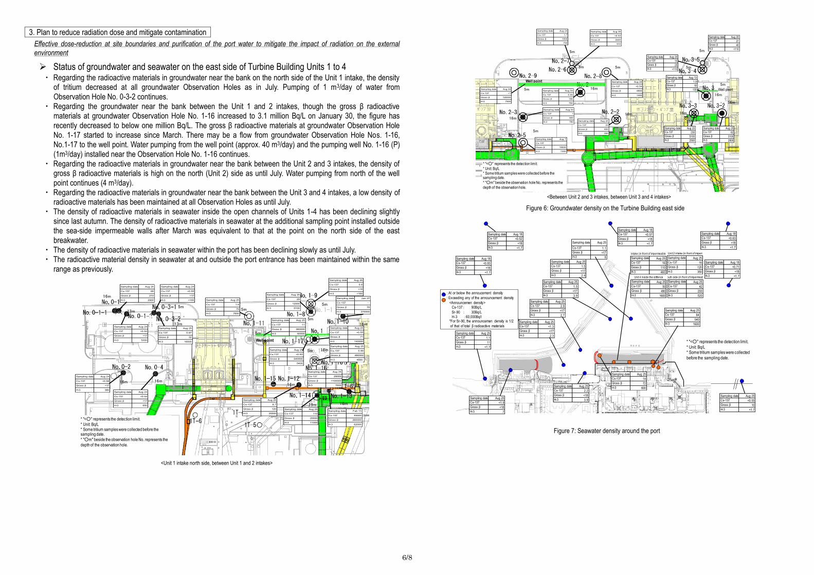
3. Plan to reduce radiation dose and mitigate contamination
Effective dose-reduction at site boundaries and purification of the port water to mitigate the impact of radiation on the external
environment
Status of groundwater and seawater on the east side of Turbine Building Units 1 to 4 ・ Regarding the radioactive materials in groundwater near the bank on the north side of the Unit 1 intake, the density
of tritium decreased at all groundwater Observation Holes as in July. Pumping of 1 m3/day of water from Observation Hole No. 0-3-2 continues.
・ Regarding the groundwater near the bank between the Unit 1 and 2 intakes, though the gross β radioactive materials at groundwater Observation Hole No. 1-16 increased to 3.1 million Bq/L on January 30, the figure has recently decreased to below one million Bq/L. The gross β radioactive materials at groundwater Observation Hole No. 1-17 started to increase since March. There may be a flow from groundwater Observation Hole Nos. 1-16, No.1-17 to the well point. Water pumping from the well point (approx. 40 m3/day) and the pumping well No. 1-16 (P) (1m3/day) installed near the Observation Hole No. 1-16 continues.
・ Regarding the radioactive materials in groundwater near the bank between the Unit 2 and 3 intakes, the density of gross β radioactive materials is high on the north (Unit 2) side as until July. Water pumping from north of the well point continues (4 m3/day).
・ Regarding the radioactive materials in groundwater near the bank between the Unit 3 and 4 intakes, a low density of radioactive materials has been maintained at all Observation Holes as until July.
・ The density of radioactive materials in seawater inside the open channels of Units 1-4 has been declining slightly since last autumn. The density of radioactive materials in seawater at the additional sampling point installed outside the sea-side impermeable walls after March was equivalent to that at the point on the north side of the east breakwater.
・ The density of radioactive materials in seawater within the port has been declining slowly as until July. ・ The radioactive material density in seawater at and outside the port entrance has been maintained within the same
range as previously.
Figure 6: Groundwater density on the Turbine Building east side
Figure 7: Seawater density around the port
<Unit 1 intake north side, between Unit 1 and 2 intakes>
<Between Unit 2 and 3 intakes, between Unit 3 and 4 intakes>
13mAug 25
0.67
32
16000
Sampling date
Cs-137
Gross β
H-3
16m
* "<○" represents the detection limit.
* Unit: Bq/L* Some tritium samples were collected before the sampling date.
* "○m" beside the observation hole No. represents the
depth of the observation hole.
5m
5m
5m5m
16m
16m
16m19m
16m
5m13m
16m16m
Aug 24
68
210
2900
Sampling date
Cs-137
Gross β
H-3
Aug 24
<0.58
<17
380
Gross β
H-3
Cs-137
Sampling date
Aug 24
<0.55
<17
<100
Cs-137
Gross β
Sampling date
H-3
Aug 25
<0.55
71
140000H-3
Cs-137
Gross β
Sampling date
Aug 25
29
12000
5100
Cs-137
Gross β
Sampling date
H-3
Aug 26
5.6
<18
<100
Cs-137
Gross β
H-3
Sampling date
Aug 25
0.89
480000
4500
Sampling date
Cs-137
Gross β
H-3
Aug 25
<0.83
540000
5400
Cs-137
Sampling date
Gross β
H-3
Aug 25
11
360000
60000
Gross β
Sampling date
H-3
Cs-137
Aug 24
<0.54
<17
650
Gross β
H-3
Sampling date
Cs-137
5m
Jan 27
-
78
270000
Sampling date
Cs-137
Gross β
H-3
5m
Aug 25
110
20000
11000
Sampling date
Cs-137
Gross β
H-3
Aug 25
1.6
75
7600
Cs-137
Gross β
Sampling date
H-3
Aug 25
29000
1100000
7600
Sampling date
Cs-137
Gross β
H-3
Aug 24
<0.54
<17
5200
Cs-137
Gross β
H-3
Sampling date
Feb 13
93000
260000
62000
Sampling date
Cs-137
Gross β
H-3
16m
Aug 25
8.7
120
20000
Cs-137
Gross β
H-3
Sampling date
Well point
5m5m
16m16m
5m
5m
16m
16m
5m
5m
Well point
Well point
* "<○" represents the detection limit.
* Unit: Bq/L* Some tritium samples were collected before the sampling date.
* "○m" beside the observation hole No. represents the
depth of the observation hole.
16m
5m
Aug 26
<0.53
2400
910
Sampling date
Cs-137
Gross β
H-3
Aug 7
-
19000
1300H-3
Cs-137
Gross β
Sampling date
Aug 24
<1
120000
7500
Cs-137
Gross β
Sampling date
H-3
Aug 24
22
400
350
Sampling date
Gross β
H-3
Cs-137
Aug 13
1.9
18
130H-3
Sampling date
Cs-137
Gross β
Aug 24
1
800
780
Cs-137
Gross β
H-3
Sampling date
5m
Aug 24
0.55
190
700
Gross β
Sampling date
Cs-137
H-3
Aug 20
15
25
<110H-3
Cs-137
Sampling date
Gross β
Aug 20
62
3100
2800
Sampling date
Cs-137
Gross β
H-3
Aug 20
21
40
<110
Cs-137
Gross β
Sampling date
H-3
Aug 24
<0.54
4800
1400
Sampling date
Cs-137
Gross β
H-3
Aug 20
230
5100
2500
Cs-137
Sampling date
Gross β
H-3
16m
Aug 24
1.7
1000
730
Cs-137
Sampling date
Gross β
H-3
* "<○" represents the detection limit.
* Unit: Bq/L* Some tritium samples were collected
before the sampling date.
Aug 25
<1.9
<18
7
Sampling date
Cs-137
Gross β
H-3
Aug 25
2.2
<18
3.9
Cs-137
Gross β
H-3
Sampling date
Aug 25
1.5
<17
3.9
Sampling date
Cs-137
Gross β
H-3
Aug 25
2.9
<17
2.7
Sampling date
Cs-137
H-3
Gross β
Aug 25
<1.3
<17
2.3
Sampling date
Gross β
Cs-137
H-3
Aug 25
1.5
<17
2.4
Sampling date
Cs-137
Gross β
H-3
Aug 25
1.1
11
<1.7
Sampling date
H-3
Cs-137
Gross β
Aug 25
<0.55
10
<1.7
Sampling date
Cs-137
Gross β
H-3
Aug 25
1.1
<17
8
Sampling date
Cs-137
Gross β
H-3Aug 18
<0.83
<16
<1.7
Cs-137
Sampling date
Gross β
H-3
Aug 18
<0.52
<18
<1.7H-3
Cs-137
Gross β
Sampling date
Aug 18
<0.57
<18
<1.7
Sampling date
Cs-137
Gross β
H-3
Aug 18
<0.63
<18
<1.7
Gross β
H-3
Cs-137
Sampling date
Aug 18
<0.71
<18
<1.7
Cs-137
Gross β
H-3
Sampling date
Aug 25
14
72
600H-3
Cs-137
Gross β
Sampling date
Aug 25
16
110
460
Gross β
H-3
Cs-137
Unit 1 intake (in front of impermeable walls)
Sampling date Aug 25
16
120
350
Sampling date
Cs-137
Gross β
H-3
Unit 2 intake (in front of impermeable walls)
Aug 25
64
540
1600H-3
Cs-137
Gross β
Sampling date
Aug 25
50
490
1600
Sampling date
H-3
Cs-137
Gross β
Unit 4 inside the siltfence
Aug 25
42
200
520H-3
Intake south side (in front of impermeable walls)
Sampling date
Cs-137
Gross β: At or below the annoucement density
: Exceeding any of the announcement density
<Announcemen density>Cs-137: 90Bq/L
Sr-90 : 30Bq/LH-3 :60,000Bq/l
*For Sr-90, the announcemen density is 1/2
of that of total β radioactive materials
7/8
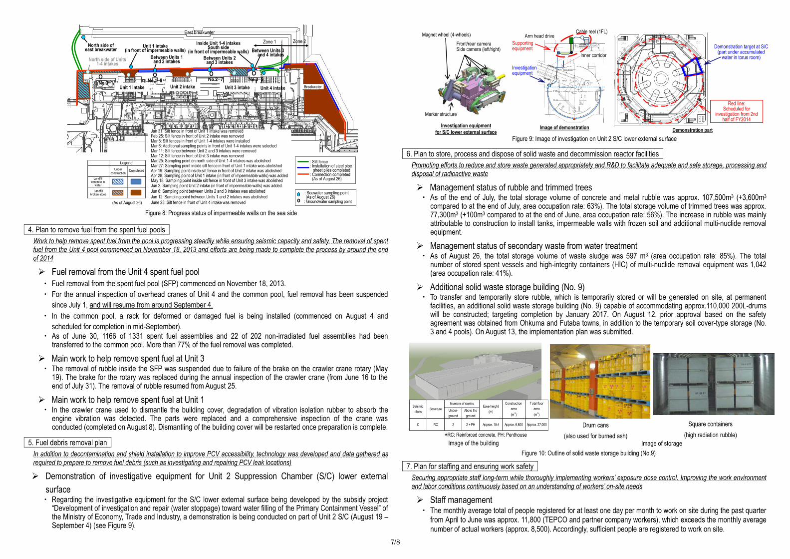
4. Plan to remove fuel from the spent fuel pools
Work to help remove spent fuel from the pool is progressing steadily while ensuring seismic capacity and safety. The removal of spent
fuel from the Unit 4 pool commenced on November 18, 2013 and efforts are being made to complete the process by around the end
of 2014
Fuel removal from the Unit 4 spent fuel pool
・ Fuel removal from the spent fuel pool (SFP) commenced on November 18, 2013.
・ For the annual inspection of overhead cranes of Unit 4 and the common pool, fuel removal has been suspended
since July 1, and will resume from around September 4.
・ In the common pool, a rack for deformed or damaged fuel is being installed (commenced on August 4 and
scheduled for completion in mid-September).
・ As of June 30, 1166 of 1331 spent fuel assemblies and 22 of 202 non-irradiated fuel assemblies had been transferred to the common pool. More than 77% of the fuel removal was completed.
Main work to help remove spent fuel at Unit 3 ・ The removal of rubble inside the SFP was suspended due to failure of the brake on the crawler crane rotary (May
19). The brake for the rotary was replaced during the annual inspection of the crawler crane (from June 16 to the end of July 31). The removal of rubble resumed from August 25.
Main work to help remove spent fuel at Unit 1 ・ In the crawler crane used to dismantle the building cover, degradation of vibration isolation rubber to absorb the
engine vibration was detected. The parts were replaced and a comprehensive inspection of the crane was conducted (completed on August 8). Dismantling of the building cover will be restarted once preparation is complete.
5. Fuel debris removal plan
In addition to decontamination and shield installation to improve PCV accessibility, technology was developed and data gathered as
required to prepare to remove fuel debris (such as investigating and repairing PCV leak locations)
Demonstration of investigative equipment for Unit 2 Suppression Chamber (S/C) lower external
surface ・ Regarding the investigative equipment for the S/C lower external surface being developed by the subsidy project
“Development of investigation and repair (water stoppage) toward water filling of the Primary Containment Vessel” of the Ministry of Economy, Trade and Industry, a demonstration is being conducted on part of Unit 2 S/C (August 19 – September 4) (see Figure 9).
6. Plan to store, process and dispose of solid waste and decommission reactor facilities
Promoting efforts to reduce and store waste generated appropriately and R&D to facilitate adequate and safe storage, processing and
disposal of radioactive waste
Management status of rubble and trimmed trees ・ As of the end of July, the total storage volume of concrete and metal rubble was approx. 107,500m3 (+3,600m3
compared to at the end of July, area occupation rate: 63%). The total storage volume of trimmed trees was approx. 77,300m3 (+100m3 compared to at the end of June, area occupation rate: 56%). The increase in rubble was mainly attributable to construction to install tanks, impermeable walls with frozen soil and additional multi-nuclide removal equipment.
Management status of secondary waste from water treatment ・ As of August 26, the total storage volume of waste sludge was 597 m3 (area occupation rate: 85%). The total
number of stored spent vessels and high-integrity containers (HIC) of multi-nuclide removal equipment was 1,042 (area occupation rate: 41%).
Additional solid waste storage building (No. 9) ・ To transfer and temporarily store rubble, which is temporarily stored or will be generated on site, at permanent
facilities, an additional solid waste storage building (No. 9) capable of accommodating approx.110,000 200L-drums will be constructed; targeting completion by January 2017. On August 12, prior approval based on the safety agreement was obtained from Ohkuma and Futaba towns, in addition to the temporary soil cover-type storage (No. 3 and 4 pools). On August 13, the implementation plan was submitted.
7. Plan for staffing and ensuring work safety
Securing appropriate staff long-term while thoroughly implementing workers’ exposure dose control. Improving the work environment
and labor conditions continuously based on an understanding of workers’ on-site needs
Staff management ・ The monthly average total of people registered for at least one day per month to work on site during the past quarter
from April to June was approx. 11,800 (TEPCO and partner company workers), which exceeds the monthly average number of actual workers (approx. 8,500). Accordingly, sufficient people are registered to work on site.
Figure 8: Progress status of impermeable walls on the sea side
Figure 9: Image of investigation on Unit 2 S/C lower external surface
Front/rear camera Side camera (left/right)
Magnet wheel (4-wheels)
Marker structure
Investigation equipment
for S/C lower external surface Image of demonstration
Demonstration part
Supporting equipment
Investigation equipment
Demonstration target at S/C (part under accumulated
water in torus room)
Red line: Scheduled for
investigation from 2nd half of FY2014
Figure 10: Outline of solid waste storage building (No.9)
Image of the building
*RC: Reinforced concrete, PH: Penthouse
Image of storage
Drum cans
(also used for burned ash)
Square containers
(high radiation rubble)
: Silt fence: Installation of steel pipe
sheet piles completed: Connection completed
(As of August 26)
: Seawater sampling point(As of August 26)
: Groundwater sampling point
North side of Units 1-4 intakes
North side of east breakwater
No.0-1Unit 1 intake
No.1-9Unit 2 intake
No.2-7
Between Units 2 and 3 intakes
Unit 3 intake
No.3-5
Between Units 3 and 4 intakes
Unit 4 intake
Zone 2Zone 1Inside Unit 1-4 intakesSouth side
(in front of impermeable walls)
East breakwater
Unit 1 intake(in front of impermeable walls)
Jan 31: Silt fence in front of Unit 1 intake was removedFeb 25: Silt fence in front of Unit 2 intake was removedMar 5: Silt fences in front of Unit 1-4 intakes were installedMar 6: Additional sampling points in front of Unit 1-4 intakes were selectedMar 11: Silt fence between Unit 2 and 3 intakes were removedMar 12: Silt fence in front of Unit 3 intake was removedMar 25: Sampling point on north side of Unit 1-4 intakes was abolishedMar 27: Sampling point inside silt fence in front of Unit 1 intake was abolishedApr 19: Sampling point inside silt fence in front of Unit 2 intake was abolishedApr 28: Sampling point of Unit 1 intake (in front of impermeable walls) was addedMay 18: Sampling point inside silt fence in front of Unit 3 intake was abolishedJun 2; Sampling point Unit 2 intake (in front of impermeable walls) was added
Jun 6: Sampling point between Units 2 and 3 intakes was abolished
Jun 12: Sampling point between Units 1 and 2 intakes was abolished
June 23: Silt fence in front of Unit 4 intake was removed
埋立
水中コン
埋立
割栗石
凡例
施工中 施工済
(As of August 26)
Between Units 1 and 2 intakes
Breakwater
Legend
Under construction
Completed
Landfill concrete in
water
Landfill broken stone
Under-
ground
Above the
ground
C RC 2 2 + PH Approx. 15.4 Approx. 6,800 Approx. 27,000
Construction
area
(m2)
Total floor
area
(m2)
Seismic
classStructure
Number of storiesEave height
(m)
Arm head drive Cable reel (1FL)
Inner corridor
8/8
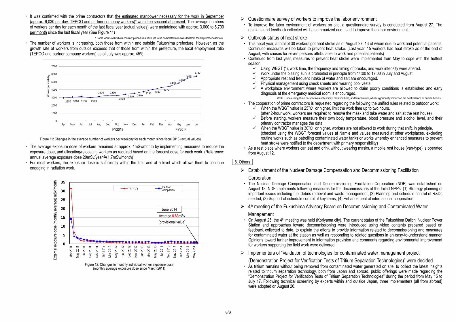
・ It was confirmed with the prime contractors that the estimated manpower necessary for the work in September (approx. 6,030 per day: TEPCO and partner company workers)* would be secured at present. The average numbers of workers per day for each month of the last fiscal year (actual values) were maintained with approx. 3,000 to 5,700 per month since the last fiscal year (See Figure 11)
・ The number of workers is increasing, both those from within and outside Fukushima prefecture. However, as the growth rate of workers from outside exceeds that of those from within the prefecture, the local employment ratio (TEPCO and partner company workers) as of July was approx. 45%.
・ The average exposure dose of workers remained at approx. 1mSv/month by implementing measures to reduce the exposure dose, and allocating/relocating workers as required based on the forecast dose for each work. (Reference: annual average exposure dose 20mSv/year≒1.7mSv/month)
・ For most workers, the exposure dose is sufficiently within the limit and at a level which allows them to continue engaging in radiation work.
Questionnaire survey of workers to improve the labor environment ・ To improve the labor environment of workers on site, a questionnaire survey is conducted from August 27. The
opinions and feedback collected will be summarized and used to improve the labor environment.
Outbreak status of heat stroke ・ This fiscal year, a total of 30 workers got heat stroke as of August 27, 13 of whom due to work and potential patients.
Continued measures will be taken to prevent heat stroke. (Last year, 15 workers had heat stroke as of the end of August, with causes for seven persons attributable to work and potential patients)
・ Continued from last year, measures to prevent heat stroke were implemented from May to cope with the hottest season. Using WBGT (*), work time, the frequency and timing of breaks, and work intensity were altered. Work under the blazing sun is prohibited in principle from 14:00 to 17:00 in July and August. Appropriate rest and frequent intake of water and salt are encouraged. Physical management using check sheets and wearing cool vests. A workplace environment where workers are allowed to claim poorly conditions is established and early
diagnosis at the emergency medical room is encouraged.
・ The cooperation of prime contractors is requested regarding the following the unified rules related to outdoor work: When the WBGT value is 25℃ or higher, limit the work time up to two hours.
(after 2-hour work, workers are required to remove the mask and take water and salt at the rest house) Before starting, workers measure their own body temperature, blood pressure and alcohol level, and their
primary contractor manages the data. When the WBGT value is 30℃ or higher, workers are not allowed to work during that shift, in principle.
(checked using the WBGT forecast values at Namie and values measured at other workplaces, excluding routine works such as patrolling contaminated water tanks or works whereby enhanced measures to prevent heat stroke were notified to the department with primary responsibility)
・ As a rest place where workers can eat and drink without wearing masks, a mobile rest house (van-type) is operated from August 12.
8. Others
Establishment of the Nuclear Damage Compensation and Decommissioning Facilitation
Corporation ・ The Nuclear Damage Compensation and Decommissioning Facilitation Corporation (NDF) was established on
August 18. NDF implements following measures for the decommissions of the failed NPPs: (1) Strategy planning of important issues including fuel debris retrieval and waste management, (2) Planning and schedule control of R&Ds needed, (3) Support of schedule control of key items, (4) Enhancement of international cooperation.
4th meeting of the Fukushima Advisory Board on Decommissioning and Contaminated Water
Management ・ On August 25, the 4th meeting was held (Koriyama city). The current status of the Fukushima Daiichi Nuclear Power
Station and approaches toward decommissioning were introduced using video contents prepared based on feedback collected to date, to explain the efforts to provide information related to decommissioning and measures for contaminated water at the station as well as responding to related questions in an easy-to-understand manner. Opinions toward further improvement in information provision and comments regarding environmental improvement for workers supporting the field work were delivered.
Implementers of “Validation of technologies for contaminated water management project
(Demonstration Project for Verification Tests of Tritium Separation Technologies)” were decided ・ As tritium remains without being removed from contaminated water generated on site, to collect the latest insights
related to tritium separation technology, both from Japan and abroad, public offerings were made regarding the “Demonstration Project for Verification Tests of Tritium Separation Technologies” during the period from May 15 to July 17. Following technical screening by experts within and outside Japan, three implementers (all from abroad) were adopted on August 26.
* Some works with which contract procedures have yet to be completed are excluded from the September estimate.
WBGT: Index using three perspectives of humidity, radiation heat, and temperature, which significantly impact on the heat balance of human bodies
Figure 11: Changes in the average number of workers per weekday for each month since fiscal 2013 (actual values)
2950 3060 3130 2990
3130 3290
3220 3410 3540
3730 4020
4270
4450 4840
5490 5730
0
1000
2000
3000
4000
5000
6000
7000
Apr May Jun Jul Aug Sep Oct Nov Dec Jan Feb Mar Apr May Jun Jul
Wor
kers
per
wee
kday
FY2014 FY2013
0
5
10
15
20
25
30
35
H2
3.3
H2
3.5
H2
3.7
H2
3.9
H2
3.1
1
H2
4.1
H2
4.3
H2
4.5
H2
4.7
H2
4.9
H2
4.1
1
H2
5.1
H2
5.3
H2
5.5
H2
5.7
H2
5.9
H2
5.1
1
H2
6.1
H2
6.3
H2
6.5
外部
被ば
く線
量 (
月平
均線
量 )
mS
v
東電社員 協力企業
June 2014
Average 0.83mSv
(provisional value)
Figure 12: Changes in monthly individual worker exposure dose (monthly average exposure dose since March 2011)
Ext
erna
l exp
osur
e do
se (
mon
thly
ave
rage
) m
Sv/
mon
th
TEPCO Partner companies
Mar
201
1
May
201
1
Jul 2
011
Sep
201
1
Nov
201
1
Jan
2012
Mar
201
2
May
201
2
Jul 2
012
Sep
201
2
Nov
201
2
Jan
2013
Mar
201
3
May
201
3
Jul 2
013
Sep
201
3
Nov
201
3
Jan
2014
Mar
201
4
May
201
4

Cesium-134: 3.3 (2013/10/17) → ND(1.1) Cesium-137: 9.0 (2013/10/17) → 1.5 Gross β: 74 (2013/ 8/19) → ND(17) Tritium: 67 (2013/ 8/19) → 3.9
Legal discharge
limit
Cesium-134 60
Cesium-137 90
Strontium-90 (strongly correlate with Gross β)
30
Tritium 60,000
Sea side impermeable wall
Silt fence
Cesium-134: 4.4 (2013/12/24) → ND(1.4) Cesium-137: 10 (2013/12/24) → 2.9 Gross β: 60 (2013/ 7/ 4) → ND(17) Tritium: 59 (2013/ 8/19) → 2.7
Cesium-134: 5.0 (2013/12/2) → ND(1.5) Cesium-137: 8.4 (2013/12/2) → ND(1.3) Gross β: 69 (2013/8/19) → ND(17) Tritium: 52 (2013/8/19) → 2.3
Cesium-134: 2.8 (2013/12/2) → ND(1.7) Cesium-137: 5.8 (2013/12/2) → ND(1.9) Gross β: 46 (2013/8/19) → ND(18) Tritium: 24 (2013/8/19) → 7.0
Cesium-134: 3.5 (2013/10/17) → ND(1.1) Cesium-137: 7.8 (2013/10/17) → 1.5 Gross β: 79 (2013/ 8/19) → ND(17) Tritium: 60 (2013/ 8/19) → 2.4
Cesium-134: 5.3 (2013/8/ 5) → ND(1.8) Cesium-137: 8.6 (2013/8/ 5) → 2.2 Gross β: 40 (2013/7/ 3) → ND(18) Tritium: 340 (2013/6/26) → 3.9
Below 1/3
Below 1/5 Below 1/4
Below 1/20
Below 1/2
Below 1/3
Below 1/2
Below 1/80
Below 1/3
Below 1/6
Below 1/4
Below 1/10
Below 1/3
Below 1/3
Below 1/3
Below 1/20
Below 1/3
Below 1/6
Below 1/4
Below 1/20
Below 1/3
Below 1/2
Below 1/3
Cesium-134: 3.3 (2013/12/24) → ND(1.1) Cesium-137: 7.3 (2013/10/11) → 1.1 Gross β: 69 (2013/ 8/19) → ND(17) Tritium: 68 (2013/ 8/19) → 8.0
Below 1/3
Below 1/6
Below 1/4
Below 1/8
Below 7/10
Cesium-134: 32 (2013/10/11) → 4.5 Cesium-137: 73 (2013/10/11) → 14 Gross β: 320 (2013/ 8/12) → 72 Tritium: 510 (2013/ 9/ 2) → 600
Below 1/7
Below 1/5
Below 1/4
Cesium-134: 13 Cesium-137: 42 Gross β: 200 Tritium: 520
Cesium-134: 5.6 Cesium-137: 16 Gross β: 110 Tritium: 460
Cesium-134: 4.5 Cesium-137: 16 Gross β: 120 Tritium: 350 * *
* * Monitoring commenced in or after
March 2014
Cesium-134: 28 (2013/ 9/16)→ 19 Cesium-137: 53 (2013/12/16)→ 64 Gross β: 390 (2013/ 8/12)→ 470 Tritium: 650 (2013/ 8/12)→ 1,600
Below 7/10
Cesium-134: 62 (2013/ 9/16)→ 16 Cesium-137: 140 (2013/ 9/16)→ 50 Gross β: 360 (2013/ 8/12)→ 490 Tritium: 400 (2013/ 8/12)→ 1,600
Below 1/3 Below 1/2
Status of seawater monitoring within the port (comparison between the highest values in 2013 and the latest values)
“The highest value” → “the latest value (sampled during August 18-25)”; unit (Bq/L); ND represents a value below the detection limit
Summary of
TEPCO data as
of August 27
【Port entrance】
【South side
in the port】
【East side in the port】
【West side in the port】
【North side in the port 】
【In front of Unit 6 intake】 【In front of shallow
draft quay】
Source: TEPCO website
Analysis results on nuclides of
radioactive materials around
Fukushima Daiichi Nuclear Power
Station
http://www.tepco.co.jp/nu/fukushima
-np/f1/smp/index-j.html
Appendix 1
【East side of port entrance (offshore 1km)】
【South side of south breakwater(offshore 0.5km)】
【North side of north breakwater(offshore 0.5km)】
Unit 1 Unit 2 Unit 3 Unit 4
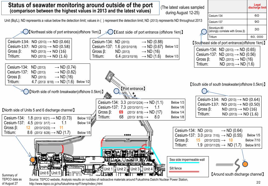
Unit (Bq/L); ND represents a value below the detection limit; values in ( ) represent the detection limit; ND (2013) represents ND throughout 2013
Source: TEPCO website, Analysis results on nuclides of radioactive materials around Fukushima Daiichi Nuclear Power Station,
http://www.tepco.co.jp/nu/fukushima-np/f1/smp/index-j.html
【North side of Units 5 and 6 discharge channel】
【Around south discharge channel】
Status of seawater monitoring around outside of the port (comparison between the highest values in 2013 and the latest values)
Summary of
TEPCO data as
of August 27
【Northeast side of port entrance(offshore 1km)】
【Port entrance】
Sea side impermeable wall Silt fence
(The latest values sampled
during August 12-25)
Legal discharge limit
Cesium-134 60
Cesium-137 90
Strontium-90 (strongly correlate with Gross β)
30
Tritium 60,000
Cesium-134: ND (2013) → ND (0.66) Cesium-137: ND (2013) → ND (0.58) Gross β: ND (2013) → ND (16) Tritium: ND (2013) → ND (1.6)
Cesium-134: ND (2013) → ND (0.88) Cesium-137: 1.6 (2013/10/18) → ND (0.67) Gross β: ND (2013) → ND (16) Tritium: 6.4 (2013/10/18) → ND (1.6)
Below 1/2
Below 1/3
Cesium-134: ND (2013) → ND (0.65) Cesium-137: ND (2013) → ND (0.56) Gross β: ND (2013) → ND (16) Tritium: ND (2013) → ND (1.6)
Cesium-134: ND (2013) → ND (0.74) Cesium-137: ND (2013) → ND (0.82) Gross β: ND (2013) → ND (16) Tritium: 4.7 (2013/ 8/18) → ND (1.6) Below 1/2
Cesium-134: ND (2013) → ND (0.64) Cesium-137: ND (2013) → ND (0.50) Gross β: ND (2013) → ND (16) Tritium: ND (2013) → ND (1.6)
Cesium-134: 3.3 (2013/12/24) → ND (1.1) Cesium-137: 7.3 (2013/10/11) → 1.1 Gross β: 69 (2013/ 8/19) → ND (17) Tritium: 68 (2013/ 8/19) → 8.0
Below 1/3
Below 1/6
Below 1/4
Below 1/8 Cesium-134: 1.8 (2013/ 6/21) → ND (0.73) Cesium-137: 4.5 (2013/ 3/17) → 1.1 Gross β: 12 (2013/12/23) → 11 Tritium: 8.6 (2013/ 6/26) → ND (1.7)
Below 1/2
Below 1/4
Below 1/5 Cesium-134: ND (2013) → ND (0.64) Cesium-137: 3.0 (2013/ 7/15) → ND (0.55) Gross β: 15 (2013/12/23) → 10 Tritium: 1.9 (2013/11/25) → ND (1.7)
2/2
Unit 6 Unit 5
Below 7/10
Below 1/5
Below 9/10
【Southeast side of port entrance(offshore 1km)】

MP-1
MP-2
MP-3
MP-4
MP-5
MP-6
MP-8
H2
Unit 1
Unit 2
Unit 3
Unit 4
Unit 5
Unit 6
G
B
H5 H6
H4
C
E
F
F
F
Main Anti-Earthquake
Building
H1
0m 100m 500m 1000m
Site boundary
D H9
Underground reservoirs
Temporary trimmed trees storage pool
Rubble
Rubble
H3
H8
Rubble
Rubble
Rubble
Rubble
Rubble
Rubble
Rubble
Rubble
Trimmed trees
Rubble
Temporary trimmed trees storage pool
Rubble
Spent absorption vessel temporary storage
G6
C
Rubble
Rubble
Rubble
Rubble
Trimmed trees
G3・G4・G5
J MP-7
Rubble
Common pool Temporary rest house
outside the site
Tank installation status
Access control facility
Large rest house (Under construction)
Administration Office Building
(planned)
Temporary Administration Office
Building (planned)
Inside the rubble storage tent
Rubble storage area
Trimmed trees area
Mid-/ low-level contaminated water
High-level contaminated water tank
Dry cask temporary storage facility
Multi-nuclide removal equipment
Trimmed trees area (planned)
Mid-/ low-level contaminated water tank (planned)
High-level contaminated water tank (planned)
Rubble storage area (planned)
Treatment facility for sub-drain water (planned)
TEPCO Fukushima Daiichi Nuclear Power Station Site Layout
Appendix 2
August 28, 2014
Rubble storage tent
Temporary soil cover type storage
Futaba town
Town boundary
Mega float
Ohkuma town
Rubble (outdoor accumulation)
Chiller for reactor water injection facility
Sea side impermeable wall
(Instllation underway)
Temporary trimmed trees storage pool
Cesium absorption apparatus (Incineration Workshop Building)
Decontamination instruments (Process Building)
Cesium absorption vessel temporary storage
Temporary waste sludge storage
High-level accumulated water reception tank
(emergency reception)
Mid-/ low-level fresh water tank
Trimmed trees (outdoor accumulation)
Spent absorption vessel temporary storage
Spent absorption vessel temporary storage
(multi-nuclide removal equipment, etc.)
Provided by Japan Space Imaging Corporation, (C)DigitalGlobe Temporary waste sludge storage
Water desalinations (RO)
Water desalinations (evaporative concentration)
Groundwater bypass temporary storage tank
Underground reservoirs
Additional multi-nuclide removal equipment (planned)
High-performance multi-nuclide removal equipment (planned)
Trimmed trees
Miscellaneous Solid Waste Volume Reduction
Treatment Building (Instllation underway)
Trimmed trees
Temporary trimmed trees storage pool
Temporary trimmed trees storage pool
Multi-nuclide removal
Dry cask temporary
storage facility
Purification system for subdrain water
2nd cesium absorption apparatus
(HTI Building)
Vehicle screening and decontamination
site
Vehicles maintenance site
Rubble
Land-side impermeable walls with frozen soil (Instllation underway)
Pipe route
Frozen soil impermeable wall demonstration test
Temporary trimmed trees storage pool
Rubble (container storage)
Rubble (outdoor accumulation)
Solid waste storage
2012
Attachment 3
20152013 2014
Status of efforts on various plans (Part 1)
Unit 3
Pla
n fo
r re
trie
ving
fuel
from
spe
nt fu
el p
ool
Challenges
Unit 4
Reactor cooling plan
Unit 1
Unit 2
Phase 1 (no later than 2 years after the completion of the current efforts) Phase 2 (Early period)
Review on fuel removing method
Improvement of the reliability of the circulating water injection cooling system (water intake from the turbine building) ( Review/implement measures to strengthen some materials for pipes, etc./improve earthquake resistance)
Reliability improvement measures for the lines taking water supplies from the condensate water storage tanks of Units 1 to 3
1回目 2回目 ☆ 格納容器内調査の実現性も含めて検討中 常設温度計の設置 常設温度計の設置
Maintenance and monitoring of the cold shut down condition of nuclear reactor (by continuous monitoring on the continuation of water injection and parameters including temperature etc., preservation and improvement of reliability through maintenance and management)
Partial observation of the PCV
Water source: Condensate water storage tank for Units 1 to 3 Water source: Treated water buffer tank
2号機圧力容器代替温度計の設置 1回目 2回目
▽Objective: Completion of
switching to the equipment for water intake from the reactor building (or from the bottom of the PCV)
Review on water take from reactor building (or from the bottom of the PCV) - Construction work Switching among the water intake equipment (sequential)
Inspection/review for early construction of the Construction of circulation loop in the building (for Units 1 to 3)
Review on the method for inserting alternative thermometer in Unit 1 RPV* Narrowing-down of candidate systems for inserting alternative thermometer in Unit 1 RPV
Pool circulation cooling (preservation/improvement of reliability by maintenance management and facility update etc.)
Review on the method for inserting alternative thermometer in Unit 3 RPV*
Consideration/preparation for the decontamination and shielding in the building
Pool circulation cooling (preservation/improvement of reliability by maintenance management and facility update etc.)
Decontamination/shielding, restoration of fuel handling equipment
Pool circulation cooling (preservation/improvement of reliability by maintenance management and facility update etc.)
Fuel removal Consideration, design and manufacturing of on-site shipping containers
Design and manufacturing of crane/fuel handling machines
Design and manufacturing of fuel removal cover
Pool circulation cooling (preservation/improvement of reliability by maintenance management and facility update etc.)
Construction of fuel removal cover/installation of fuel handling equipment
Removal of debris In the pool/fuel check etc.
Fuel removal
Installation of thermometer in Unit 2 RPV (including inspection in nuclear reactors)
*The time for executing the installation work will be determined after on -site studies etc., on the basis of the status of environmental improvement by means of decontamination/shielding.
Selection of a fuel/fuel debris removing plan
Selection of a fuel/fuel debris removing plan
Selection of a fuel/fuel debris removing plan
: Main processes
: Sub-main processes
Preparatory work/debris removing work
Construction of fuel removal cover/installation of fuel handling equipment
Removal of debris, decontamination and shielding in the
Removal of debris In the pool/fuel check
Modification/recovery of building cover
As of August 28, 2014▼
HP
3-1
Narrowing-down of candidate systems for inserting alternative thermometer in Unit 3 RPV
The circulating injection cooling system (water intake from the reactor building (or the lower part of the reactor containment vessel))
circulation loop in the building
Partial observation of the PCV
Remote visual check of the PCV, direct measurement/evaluation of temperature etc. Remote visual check of the PCV, direct measurement/evaluation of temperature etc.
Dismantling of building cover
* Reviewed based on the progress status in the field
HP
1-1
* Reviewed based on the progress status in the field
HP
2-1
: Field work
: R&D
: Review
: Plan until last month
Green frame: Change from last month
Removal of debris, decontamination and shielding
* Reviewed based on the
progress status in the field

2012
Others
2013
Status of efforts on various plans (Part 2)
20152014F
uel d
ebris
rem
oval
pla
n
Measures to
reduce overall dose
Inspection/repair of
leaking locations of
the PCV
Challenges
Decontamination of the
inside of the building
Fuel debris
removal
Stable storage,
processing/disposal
of fuel debris after
removal
To be continued
Decontamination, shielding, etc. in the building (Work environment improvement (1))
Formulation of a comprehensive plan for exposure reduction
腐食抑制対策(窒素バブリングによる原子炉冷却水中の溶存酸素低減) 原子炉施設の解体に向けた基礎データベース(汚染状況等)の構築
格納容器漏えい箇所調査・補修に向けた研究開発(建屋間止水含む) 格納容器補修装置の設計・製作・試験等③⑥ 圧力容器/格納容器腐食に対する健全性の評価技術の開発 燃料デブリ取出に向けた研究開発(内部調査方法や装置開発等、長期的課題へ継続) 格納容器調査装置の設計・製作・試験等②
臨界評価、検知技術の開発 格納容器内調査装置の設計・製作・試験等⑤ 除染技術調査/遠隔除染装置開発 遠隔汚染調査技術の開発① 遠隔除染装置の開発① 収納缶開発(既存技術調査、保管システム検討・安全評価技術の開発他) 処理・処分技術の調査・開発 安全活動の継続、放射線管理の維持・充実、医療体制の継続確保 等
調査・データベース構築計画策定 廃棄物の処分の最適化研究 廃棄物の性状把握、物量評価等 処理・処分に関する研究開発計画の策定 協力企業を含む要員の計画的育成・配置、意欲向上策の実施 等 現場調査、現場実証(適宜) ▽目標:除染ロボット技術の確立
漏えい箇所調査(開発成果の現場実証含む) 格納容器外部からの調査 建屋内除染・遮へい等(作業環境改善①) 燃料デブリに係る計量管理方策の構築
免震重要棟の非管理区域化 検討継続
R&D toward the removal of fuel debris (to be continued to address long -term challenges including internal R&D of equipment etc.)
Development of criticality evaluation and detection technologies
Design, manufacturing and testing etc. of the equipment for inspecting the inside of the PCV (5)
Inspection from outside the PCV (including on-site demonstration of development results)
Establishment of nuclear material accountancy and control measures for the fuel debris
R&D for inspection/repair of leaking locations of the PCV (including stop leakage between buildings).
Design, manufacturing and testing etc. of the equipment for inspecting the PCV (3), (6)
Design, manufacturing and testing etc. of the equipment for inspecting the PCV (2)
Review on decontamination technology/development of remote decontamination equipment
Development of remote contamination investigation technologies (1)
Development of remote decontamination technologies (1)
Site survey and on-site demonstration
▽Objective:
Establish decontamination robot technology
[Units 1 and 3] Inspection of the basement of the nuclear reactor building, Inspection of leaking locations☆
First floor of the reactor building
Development of storage cans (surveys on existing technologies, review on storage systems/development of safety evaluation technique etc.)
Research on/development of mock-up processing/disposal technologies
[Unit 2] Inspection of the basement of the nuclear reactor building, Inspection of leaking locations☆
☆: Including on-site demonstration
Phase 1 (no later than 2 years after the completion of the current efforts) Phase 2 (Early period)
: Main processes
: Sub-main processes
Grasping of the situation of work area
Formulation of work plan in the reactor building
Formulation of work plan on the floor with damage from explosion
As of August 28, 2014▼
: Field work
: R&D
: Review
: Plan until last month
Green frame: Change from last month

2012
Status of efforts on various plans (Part 3)
20142013
Pla
n fo
r m
aint
aini
ng a
nd c
ontin
uing
the
stea
dy s
tate
of p
lant
Pla
ns to
war
d th
e re
duct
ion
in th
e ra
diat
ion
dose
and
pre
vent
ion
of th
e sp
read
of c
onta
min
atio
n in
the
entir
e po
wer
pla
nt
Site
decontamination
plan
Gas/liquid waste
2015
Challenges
Retained water
treatment plan
Plan for preventing
the spread of
marine pollution
Reduction in
radiation dose at
the site boundary
Construction of sea side water barrier wall
Objective: Implement the measures to improve the reliability of the current facilities
Improving the reliability of the current facilities, etc. (improve the reliability of transfer, processing, and storage facilities).
Replacement of branch pipe pressure hoses with PE pipes
Treatment of retained water by water treatment facilities with improved reliability
Groundwater inflow is reduced (Retained water is decreased).
Consider and implement measures to increase the processing amount Purification of on-site reservoir water
Installation of multi-nuclide removal equipment
Retained water treatment by means of existing treatment facilities
Restore sub-drain facilities, reduce the amount of groundwater inflow
(reduction in retained water) Review on sub-drain and other purification facility → Installation work
Drawdown of groundwater in the building
Sub-drain restoration work Review on sub-drain recovery methods
▽
Consideration of reducing the circular lines
Decontamination of Radioactive strontium (Sr )
目標:汚染水漏えい時における海洋汚染拡大リスクの低減▽ ▽目標:港湾内海水中の放射性物質濃度の低減(告示濃度未満) シルトフェンス追加設置
▽Objective: Reduction of the risk of spreading marine
contamination during the leakage of contaminated water
Monitoring of ground water and seawater (implemented on an ongoing basis)
Landfilling etc. in the harbor area
Objective: Reduction of the concentration of
radioactive substances contained in the seawater of
the harbor (to less than the notified concentration) Consideration of technologies for decontaminating radioactive strontium (Sr)
Seawater circulation purification Sea water purification by fibrous adsorbent material (ongoing)
Operation of the gas management system of Units 1 to 3 PCVs
Land and marine environmental monitoring (implemented in an ongoing basis)
Installation of ventilation equipment/closure of the opening of blow-out panel for Unit 2
Measurement of dust concentration at the opening of buildings etc., on-site survey
Improve the accuracy of gas monitoring
The Phase 1 (no later than 2 years after the completion of the current efforts) The Phase 2 (Early period)
Reduction of radiation dose by shielding, etc.
Reduction of radiation dose by the purification of contaminated water etc.
Land and marine environmental monitoring (implemented in an ongoing basis)
▽Objective: Control the radiation dose at the site boundaries caused by radioactive substance etc.
additionally released from the entire power plant at 1mSv/year or less
: Main processes
: Sub-main processes
Preparation work for frozen soil impermeable walls
Installation work
Installation of steel pipe sheet pile
Covering etc. of dredge soil over sea routes and berths
▽
Reduce groundwater inflow rate (Reduce accumulated water)
Measures to prevent the expansion of tank leakage (Reinforced concrete dam/embankment/replacement by closed conduits), to be taken sequentially along with the installation of tanks
Objective: Reduction to average 5 Sv/hour in the South side area on site except for around Units 1-4.
Systematic implementation of decontamination in the site of power generation plant
Groundwater bypass
installation work
As of August 28, 2014▼
: Field work
: R&D
: Review
: Plan until last month
Green frame: Change from last month
▽

2012
Common pool
Temporary cask
storage facility
2013
Status of efforts on various plans (Part 4)
20152014
Implementation system and
personnel procurement plan
Pla
n fo
r m
anag
emen
t and
pro
cess
ing/
disp
osal
of s
olid
rad
ioac
tive
was
te, a
nd th
e de
com
mis
sion
ing
of r
eact
or fa
cilit
ies
Processing/
disposal plans for
solid wastes
Plan to ensure the safety of
work
R&D
Cask for both
transport and
storage
Dry storage cask
Harbor
Challenges
Pla
n fo
r re
trie
ving
fuel
from
spe
nt fu
el p
ool
Installation of
reactor building
Fue
l deb
ris
rem
oval
pla
n
Storage and
management plans
for solid wastes
Decommissioning
plans for reactor
facilities
Preservation of the
integrity of
RPV/PCV
Cask manufacturing
Inspection of existing dry storage casks (9 pieces)
Fixation
Storage of fuel retrieved from spent fuel pool (storage and management).
Acceptance and interim storage of casks
Sequential carrying-in Already carried-in
Retrieval of fuel from the common pool
Design/manufacturing of damaged fuel racks
Installation
Development of evaluation technology for integrity against corrosion of RPV/PCV
Evaluation of long-term integrity of fuel retrieved from spent fuel pool
Examination of the processing method of damaged fuel etc. retrieved from spent fuel pool
The Phase 1 (no later than 2 years after the completion of the current efforts) The Phase 2 (Early period)
Systematic cultivation/deployment of personnel, including the cooperative companies, and implementation of measures to stimulate motivation etc.
Reduction of radiation dose in the rest area of the main office building, rest area in front of the important quake-proof building, and the important quake-proof building
: Main processes
: Sub-main processes
Continuation of secure storage equipped with adequate shielding and scattering prevention measures
多核種除去設備の設置 多核種除去設備の設置
Waste characterization (radiochemistry analysis, assessment of volume etc.)
Verification of applicability of processing/disposal technologies in Japan and foreign countries Development of R&D plan for safety processing/disposal
Establishment of vehicle maintenance shops
Evaluation of waste prevention measures
Update the storage management plan
Establishment of drum storage facility
Facility renewal plan development Evaluation of secondary wastes from water treatment and lifespan of storage containers
Development of feasible and rational decommissioning scenarios
Transfer of debris to the soil-coveried temporary storage facility
Soil covering work for felled trees
Reduction of radiation dose from stored secondary wastes from water treatment through shielding etc.
Improvement of waste reducing management policy
Improvement of waste storage management policy
Design and manufacturing of incineration plants for miscellaneous solid wastes
Installation of incineration plants for miscellaneous solid wastes
Development of storage management plans (Reduction in
generation amount/optimization
of storage)
Cask manufacturing
Establishment of decommissioning scenarios
HP
ND-1
Carrying-in of empty casks (sequential)
Design and production
Corrosion protection (Reduction in dissolved oxygen contained in reactor cooling water by means of nitrogen bubbling)
Continuation of safety activities, maintenance and enhancement of radiation management, continuous ensurement of medical services, etc.
As of August 28, 2014▼
Wharf restoration work
: Field work
: R&D
: Review
: Plan until last month
Green frame: Change from last month
* Launched
* Completed
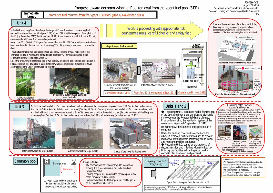
In the Mid- and Long-Term Roadmap, the target of Phase 1 involved commencing fuel removal from inside the spent fuel pool (SFP) of the 1st Unit within two years of completion of Step 2 (by December 2013). On November 18, 2013, fuel removal from Unit 4, or the 1st Unit, commenced and Phase 2 of the roadmap started.As of June 30, 1,166 of 1,331 spent fuel assemblies and 22 of 202 new fuel assemblies have been transferred to the common pool, meaning 77% of the removal has been completed to date.Though fuel removal has been suspended since July 1 due to annual inspection of the overhead cranes, it will resume from around September 4. There is no change in the scheduled removal completion within 2014.Since the procurement of storage casks was partially prolonged, the common pool run out of space. The plan was changed to transferring new fuel assemblies (all remaining 180 fuel assemblies) in the Unit 4 spent fuel pool to Unit 6.
To facilitate the installation of a cover for fuel removal, installation of the gantry was completed (March 13, 2013). Removal of rubble from the roof of the Reactor Building was completed (October 11, 2013). Currently, toward the installation of a cover for fuel removal and the fuel-handling machine on the operating floor (*1), measures to reduce the radiation dose (decontamination and shielding) are underway (from October 15, 2013). Removal of large rubble from the SFP is also underway (from December 17, 2013).
August 28, 2014Secretariat of the Team for Countermeasures for
Decommissioning and Contaminated Water Treatment1/6
Progress toward decommissioning: Fuel removal from the spent fuel pool (SFP)
Removal of rubble from the roof of the Reactor Building
Installation of cover for fuel removal
Completed in Dec. 2012 From Apr. 2012, completed in Nov. 2013
Commence fuel removal from the Spent Fuel Pool (Unit 4, November 2013)Immediate target
Steps toward fuel removal Cover(or container)
Spent fuel pool
Overhead crane
Fuel Exchanger
Transfer
Removal
Commenced in Nov. 2013
Unit 3Unit 3
Common poolCommon pool
An open space will be maintained in the common pool (Transfer to the
temporary dry cask storage facility)
Progress to date・ The common pool has been restored to the condition
whereby it can re-accommodate fuel to be handled (November 2012)
・ Loading of spent fuel stored in the common pool to dry casks commenced (June 2013)
・ Fuel removed from the Unit 4 spent fuel pool began to be received (November 2013)
Units 1 and 2Units 1 and 2
Reference
クレーン
防護柵 モジュール
Spent fuel is accepted from the common pool
Temporary dry cask (*3)
storage facilityTemporary dry cask (*3)
storage facility
Operation commenced on April 12, 2013; from the cask-storage building, transfer of 9 existing dry casks completed (May 21); fuel stored in the common pool sequentially transferred.
Measures to reduce release
● Regarding Unit 1, to remove rubble from the top of the operating floor, there are plans to dismantle the cover over the Reactor Building is planned. Prior to dismantling, the ventilation system of the cover was suspended (September 17, 2013). Dismantling will be launched once preparation is complete.When the building cover is dismantled and the rubble is removed, sufficient measures to prevent radioactive materials from scattering will be taken and monitoring will be conducted.● Regarding Unit 2, based on the progress of decontamination and shielding within the Reactor Building, the facilities will be inspected and a concrete plan examined and prepared.
<Glossary>(*1) Operating floor: During regular inspection, the roof over the reactor is opened while on the operating floor, fuel inside the core is replaced and the core internals are inspected.(*2) Cask: Transportation container for samples and equipment, including radioactive materials.
Image of the cover for fuel removal
Unit 4Unit 4
Before removal of the large rubble After removal of the large rubblePhoto taken on February 21, 2012 Photo taken on October 11, 2013
Work is proceeding with appropriate risk countermeasures, careful checks and safety first
* Some portions of these photos, in which classified information related to physical protection is included, were corrected.Fuel removal status
Loading the transportation container onto the trailer
Check of the soundness of the Reactor BuildingSince May 2012, regular quarterly inspections have been conducted, which have confirmed that the soundness of the Reactor Building has been maintained.
Check for tilt (measurement of the water level)
Check for tilt (measurement of the external wall)
Legend : Measurement pointNorth
Reactor Building Cover for fuel removal
Measures for rainwater infiltration
Measurement points Spent fuel pool
Fuel storage pool
Reactor well
North
Approx. 10m
Approx. 12m 5th floor
Optical equipment
Rainwater preventionmeasures
(Protection)
North
fuel-handling machine
Crane
Cover for fuel removal
Dismantling of the cover over Reactor Building Unit 1
To facilitate the early removal of fuel and fuel debris from the SFP, the cover over the Reactor Building will be dismantled to accelerate the removal of rubble on the operation floor. The radiation dose on the site boundaries will also increase compared to before the dismantling. However, through measures to reduce the release, the estimated impact of the release from Units 1 to 3 on the site boundaries (0.03mSv/year) will be limited.
Cask pit Storage area
Open space
Cask pit
Crane Protection
fence Modules Progress to date
・The common pool has been restored to a condition allowing it to re-accommodate fuel to be handled (November 2012)
・Loading of spent fuel stored in the common pool to dry casks commenced (June 2013)
・Fuel removed from the Unit 4 spent fuel pool began to be received (November 2013)
Transportationcontainer
①Spraying anti-scattering agents
②Removing dust and dirt by suctioning devices
③Preventing dust from being stirred up via a windbreak sheet
④ Enhancing the dust-monitoring system by installing additional monitors
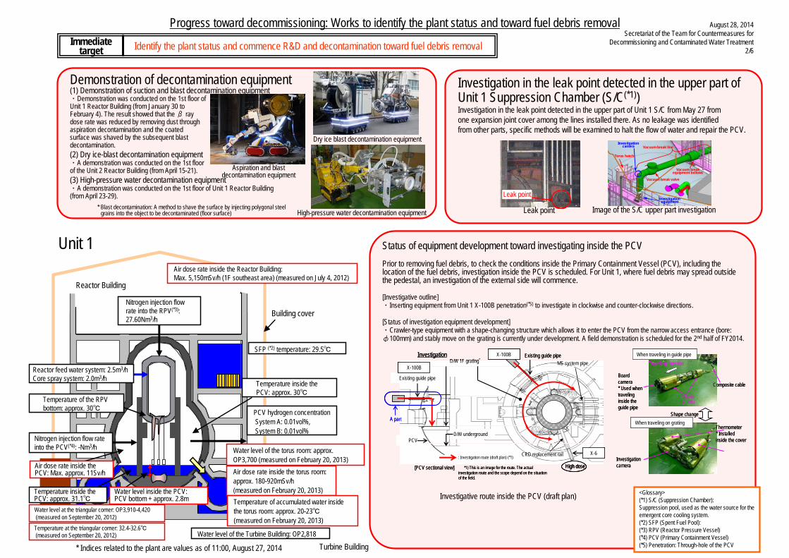
Progress toward decommissioning: Works to identify the plant status and toward fuel debris removal
Identify the plant status and commence R&D and decontamination toward fuel debris removalImmediatetarget
* Indices related to the plant are values as of 11:00, August 27, 2014
Unit 1
Turbine Building
August 28, 2014Secretariat of the Team for Countermeasures for
Decommissioning and Contaminated Water Treatment2/6
<Glossary>(*1) S/C (Suppression Chamber):
Suppression pool, used as the water source for the emergent core cooling system.
(*2) SFP (Spent Fuel Pool):(*3) RPV (Reactor Pressure Vessel)
(*4) PCV (Primary Containment Vessel)1号機
:808
0mm
ベント管
自己位置検知要素技術実証試験イメージ
長尺ケーブル処理技術実証試験イメージ(水上ボート利用)
サプレッションチェンバ(S/C)
①のベント管
の下のサンド
クッションド
レン管が外れ
ており、そこか
らの流水を確
認した
S/C 側面
トーラス室水面
④のベント管の
上部方向からト
ーラス室滞留水
面への流水を確
認した
②
③
④
⑤
⑥
⑦ ⑧
①
X-5B X-5C
X-5D
X-5E
X -5A
X-5G
X-5H
N
X-5F
②
③
④
⑤
⑥
⑦ ⑧
①
X-5B X-5C
X-5D
X-5E
X -5A
X-5G
X-5H
N
X-5F
②
③
④
⑤
⑥
⑦ ⑧
①
X-5B X-5C
X-5D
X-5E
X -5A
X-5G
X-5H
NN
X-5F
Image of the swimming investigation robot demonstration
Status of leak water from the sand cushion drain pipe and above the vent pipe
Sand cushion drain pipe
under the vent pipe (1) was
disconnected, from which
water flow was detected.
Water flow was detected from above
the vent pipe (4) to the
accumulated water surface in the torus
room.
S/C side surface
Water surface of the torus room
Vent pipe
Unit 1
Image of long cable treatment technology demonstration test (using a water boat)
Self-location detection element technology demonstration image
Suppression Chamber (S/C)
Status of equipment development toward investigating inside the PCVPrior to removing fuel debris, to check the conditions inside the Primary Containment Vessel (PCV), including the location of the fuel debris, investigation inside the PCV is scheduled. For Unit 1, where fuel debris may spread outside the pedestal, an investigation of the external side will commence.
[Investigative outline]・Inserting equipment from Unit 1 X-100B penetration(*5) to investigate in clockwise and counter-clockwise directions.
[Status of investigation equipment development]・Crawler-type equipment with a shape-changing structure which allows it to enter the PCV from the narrow access entrance (bore: φ100mm) and stably move on the grating is currently under development. A field demonstration is scheduled for the 2nd half of FY2014.
<Glossary>(*1) S/C (Suppression Chamber):Suppression pool, used as the water source for the emergent core cooling system.(*2) SFP (Spent Fuel Pool):(*3) RPV (Reactor Pressure Vessel)(*4) PCV (Primary Containment Vessel)(*5) Penetration: Through-hole of the PCV
Investigative route inside the PCV (draft plan)
D/W 1F grating゙
D/W underground
Existing guide pipe
X-6: Investigation route (draft plan) (*1)
*1) This is an image for the route. The actual investigation route and the scope depend on the situation of the field.
Existing guide pipe
[PCV sectional view]
PCV
X-100B
X-100B
High dose
A part
CRD replacement rail
MS system pipe
Board camera* Used when traveling inside the guide pipe
Composite cable
Shape change
When traveling in guide pipe
When traveling on gratingThermometer* Installed inside the cover
Investigation camera
Crawler(2 units)
Traveling directionInvestigation
D/W 1F grating゙
D/W underground
Existing guide pipe
X-6: Investigation route (draft plan) (*1)
*1) This is an image for the route. The actual investigation route and the scope depend on the situation of the field.
Existing guide pipe
[PCV sectional view]
PCV
X-100B
X-100B
High doseHigh dose
A part
CRD replacement rail
MS system pipe
Board camera* Used when traveling inside the guide pipe
Composite cable
Shape change
When traveling in guide pipe
When traveling on gratingThermometer* Installed inside the cover
Investigation camera
Crawler(2 units)
Traveling directionInvestigation
Demonstration of decontamination equipment(1) Demonstration of suction and blast decontamination equipment・Demonstration was conducted on the 1st floor of Unit 1 Reactor Building (from January 30 to February 4). The result showed that the β ray dose rate was reduced by removing dust throughaspiration decontamination and the coated surface was shaved by the subsequent blast decontamination.(2) Dry ice-blast decontamination equipment・A demonstration was conducted on the 1st floor of the Unit 2 Reactor Building (from April 15-21).(3) High-pressure water decontamination equipment・A demonstration was conducted on the 1st floor of Unit 1 Reactor Building (from April 23-29).
High-pressure water decontamination equipment
Dry ice blast decontamination equipment
Aspiration and blast decontamination equipment
* Blast decontamination: A method to shave the surface by injecting polygonal steel grains into the object to be decontaminated (floor surface)
Investigation in the leak point detected in the upper part of Unit 1 Suppression Chamber (S/C(*1))Investigation in the leak point detected in the upper part of Unit 1 S/C from May 27 from one expansion joint cover among the lines installed there. As no leakage was identified from other parts, specific methods will be examined to halt the flow of water and repair the PCV.
Image of the S/C upper part investigationLeak point
Leak point
Vacuum break line
Torus hatch
Vacuum break equipment bellows
Vacuum break valve
Investigation equipment
Investigation camera
Air dose rate inside the Reactor Building:Max. 5,150mSv/h (1F southeast area) (measured on July 4, 2012)
Building cover
Temperature inside the PCV: approx. 30℃
PCV hydrogen concentrationSystem A: 0.01vol%,System B: 0.01vol%
Water level of the torus room: approx. OP3,700 (measured on February 20, 2013)Air dose rate inside the torus room:approx. 180-920mSv/h(measured on February 20, 2013)Temperature of accumulated water inside the torus room: approx. 20-23℃(measured on February 20, 2013)
Water level of the Turbine Building: OP2,818Temperature at the triangular corner: 32.4-32.6℃(measured on September 20, 2012)
Water level at the triangular corner: OP3,910-4,420(measured on September 20, 2012)
Water level inside the PCV:PCV bottom + approx. 2.8m
Temperature inside the PCV: approx. 31.1℃
Air dose rate inside the PCV: Max. approx. 11Sv/h
Nitrogen injection flow rate into the PCV(*4): -Nm3/h
Temperature of the RPV bottom: approx. 30℃
Reactor feed water system: 2.5m3/hCore spray system: 2.0m3/h
Nitrogen injection flow rate into the RPV(*3): 27.60Nm3/h
Reactor Building
SFP (*2) temperature: 29.5℃
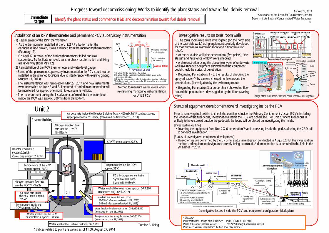
Progress toward decommissioning: Works to identify the plant status and toward fuel debris removal
Identify the plant status and commence R&D and decontamination toward fuel debris removalImmediate target
* Indices related to plant are values as of 11:00, August 27, 2014
August 28, 2014Secretariat of the Team for Countermeasures for
Decommissioning and Contaminated Water Treatment3/6
Equipment developed to measure the water level
Probe press structureX direction guide
Status of equipment development toward investigating inside the PCVPrior to removing fuel debris, to check the conditions inside the Primary Containment Vessel (PCV), including the location of the fuel debris, investigations inside the PCV are scheduled. For Unit 2, where fuel debris is unlikely to have spread outside the pedestal, the focus will be placed on investigating the inside.[Investigative outline]・Inserting the equipment from Unit 2 X-6 penetration(*1) and accessing inside the pedestal using the CRD rail
to conduct investigation.[Status of investigative equipment development]・Based on issues confirmed by the CRD rail status investigation conducted in August 2013, the investigation
method and equipment design are currently being examined. A demonstration is scheduled in the field in the 2nd half of FY2014.
<Glossary>(*1) Penetration: Through-hole of the PCV (*2) SFP (Spent Fuel Pool)(*3) RPV (Reactor Pressure Vessel) (*4) PCV (Primary Containment Vessel)(*5) Tracer: Material used to trace the fluid flow. Clay particles
Investigative issues inside the PCV and equipment configuration (draft plan)
Installation of an RPV thermometer and permanent PCV supervisory instrumentation (1) Replacement of the RPV thermometer・ As the thermometer installed at the Unit 2 RPV bottom after the
earthquake had broken, it was excluded from the monitoring thermometers (February 19).
・On April 17, removal of the broken thermometer failed and was suspended. To facilitate removal, tests to check rust formation and fixingare underway (from May 12).
(2) Reinstallation of the PCV thermometer and water-level gauge・Some of the permanent supervisory instrumentation for PCV could not be
installed in the planned locations due to interference with existing grating (August 13, 2013).
・The instrumentation was removed on May 27, 2014 and new instruments were reinstalled on June 5 and 6. The trend of added instrumentation will be monitored for approx. one month to evaluate its validity.
・The measurement during the installation confirmed that the water level inside the PCV was approx. 300mm from the bottom.
X-6 penetration
Isolation valve
Insertion tool
5. Avoiding the foothold
Chamber
Isolation valve
7. Avoiding rail holding tool
9. Travel on the grating
6. Crossing over deposit on the rail
8. Crossing over the space between rail and platform
Platform
Self-traveling equipment (draft plan)
Front camera & lightPan & tilt function
Issues before using X-6 penetration1. Removal of existing shield in front of the
penetration2. Installation of alternative shield3. Boring in the penetration hatch4. Removal of inclusion of the penetration
Measurement equipment
Alternative shield
This plan may be changed depending on the future examination status
Method to measure water levels when re-installing monitoring instrumentation
for Unit 2 PCV
Nitrogen injection flow rate into the PCV(*4): -Nm3/h
PCV hydrogen concentration System A: 0.03vol%System B: 0.03vol%
Temperature of the RPV bottom: approx. 38℃
Temperature inside the PCV: approx. 39℃
Water level of the torus room: approx. OP3,270 (measured on June 6, 2012)
Water level inside the PCV: PCV bottom + approx. 300mm
Water level of the Turbine Building: OP2,911
Air dose rate inside the PCV: Max. approx. 73Sv/h
Temperature inside the PCV: approx. 40.6℃
Air dose rate inside the torus room: 30-118mSv/h(measured on April 18, 2012)6-134mSv/h(measured on April 11, 2013)
Water level at the triangular corner: OP3,050-3,190(measured on June 28, 2012)
Temperature at the triangular corner: 30.2-32.1℃(measured on June 28, 2012)
Air dose rate inside the Reactor Building: Max. 4,400mSv/h (1F southeast area, upper penetration(*1) surface) (measured on November 16, 2011)
SFP(*2) temperature: 27.8℃
Reactor feed water system:2.0m3/hCore spray system: 2.5m3/h
Reactor BuildingNitrogen injection flow rate into the RPV(*3): 15.41Nm3/h
Unit 2
Turbine Building
① Confirm that the top reaches the surface② Confirm that the equipment reaches the bottom based on the
movement of the top③ Raise the equipment to resolve deflection when reaching the bottom* Calculate the water level based on the difference of the inserted cable
length of ① and ③
Approx. 300mmVent pipe
PCV ①Surface
PCV bottom OP 5480
Monitoring equipment(collecting pipe)
②Bottoming
Camera
③Bottom
Top for confirming the bottoming
Investigative results on torus room walls・The torus room walls were investigated (on the north side of the east-side walls) using equipment specially developed for that purpose (a swimming robot and a floor traveling robot).・At the east-side wall pipe penetrations (five points), “the status” and “existence of flow” were checked.・A demonstration using the above two types of underwater wall investigative equipment showed how the equipment could check the status of penetration.・Regarding Penetrations 1 - 5, the results of checking the sprayed tracer (*5) by camera showed no flow around the penetrations. (investigation by the swimming robot) ・Regarding Penetration 3, a sonar check showed no flow around the penetrations. (investigation by the floor traveling robot)
Swimming robot
Floor traveling robot
Penetration (3)
Image of the torus room east-side cross-sectional investigation
Penetrations investigated
T/B East-side wall
S/C
Underwater
Swimming robot
R/B 1st floor
Tracer
Sonar
(Investigative equipment insert point)
R/B torus room

Progress toward decommissioning: Works to identify the plant status and toward fuel debris removal
Identify the plant status and commence R&D and decontamination toward fuel debris removalImmediatetarget
Decontamination inside R/B・The contamination status inside the Reactor Building (R/B) was investigated by a robot (June 11-15, 2012).・To select an optimal decontamination method, decontamination samples were collected (June 29 to July 3, 2012).・To facilitate decontamination inside the Reactor Building, removal of obstacles on the 1st floor was conducted (from November 18, 2013 to March 20, 2014).
Robot for investigating the contamination status (gamma camera mounted)
* Indices related to plant are values as of 11:00, August 27, 2014
August 28, 2014Secretariat of the Team for Countermeasures for
Decommissioning and Contaminated Water Treatment4/6
Outline of the water-flow status* Main Steam Isolation Valve: A valve to shut off the steam generated from the Reactor in an emergency
Water flow was detected from the Main Steam Isolation Valve* room
On January 18, a flow of water from around the door of the Steam Isolation Valve room in the Reactor Building Unit 3 1st floor northeast area to the nearby floor drain funnel (drain outlet) was detected. As the drain outlet connects with the underground part of the Reactor Building, there is no possibility of outflow from the building.From April 23, image data has been acquired by camera and the radiation dose measured via pipes for measurement instrumentation, which connect the air-conditioning room on the Reactor Building 2nd floor with the Main Steam Isolation Valve Room on the 1st floor. On May 15, water flow from the expansion joint of one Main Steam Line was detected.This is the first leak from PCV detected in Unit 3. Based on the images collected in this investigation, the leak volume will be estimated and the need for additional investigations will be examined. The investigative results will also be utilized to examine water stoppage and PCV repair methods.
Visual check range
Blown out TIP room door
Inaccessible area for robot
Status of equipment development toward investigating inside the PCVPrior to removing fuel debris, to check the conditions inside the Primary Containment Vessel (PCV), including the location of the fuel debris, investigation inside the PCV is scheduled. For Unit 3, where there is little possibility of fuel debris spreading outside the pedestal, the focus will be placed on investigating the inside. As the water level inside the PCV is high and the penetration scheduled for use in Units 1 and 2 may decline in the water, another method needs to be examined. [Steps for investigation and equipment development](1) Investigation from X-53 penetration
・Following decontamination, a field investigation is scheduled in the areas around X-53 penetration to determine the plan for conducting the inside investigation and equipment specifications.
(2) Investigation plan following the investigation of X-53 penetration・Based on the measurement values of hydraulic head pressure inside the PCV, X-6 penetration may decline. It is
estimated that access to X-6 penetration is difficult.・For access from another penetration, approaches such as “further downsizing the equipment” or “moving in water to
access the pedestal” are necessary and will be examined.
<Glossary>(*1) SFP (Spent Fuel Pool)(*2) RPV (Reactor Pressure Vessel)(*3) PCV (Primary Containment Vessel)
CRD
PCV
PlatformCRD rail
Pedestal
opening
X-6 penetration1F grating
opening part
X-53 penetration
Workers access
entrance
CRD
PCV
PlatformCRD rail
Pedestal
opening
X-6 penetration1F grating
opening part
X-53 penetration
Workers access
entrance
Main Steam Isolation Valve room
Floor drain funnel
N
Water flow
PCV
side
Main Steam Line
Expansion joint
Expansion joint
Leak point
構台
安全第一福島第一安全第一福島第一 安全
第一
福島第一
安全第一福島第一 安全第一福島第一 安全第一福島第一
Unit 3
Reactor feed water system: 1.9m3/hCore spray system: 2.3m3/h
Nitrogen injection flow rate into the PCV(*3): -Nm3/h
PCV hydrogen concentration System A: 0.06vol%System B: 0.03vol%
Temperature of the RPV bottom: approx. 35℃
Temperature inside the PCV: approx. 35℃
Water level of the Turbine Building: OP2,698
Water level inside the PCV: unconfirmed
Water level at the triangular corner: OP3,150 (measured on June 6, 2012)
Reactor Building
SFP(*1) temperature: 28.5℃
Air dose rate inside the Reactor Building: Max. 4,780mSv/h (1F northeast area, in front of the equipment hatch) (measured on November 27, 2012)
Water level of the torus room: approx. OP3,370 (measured on June 6, 2012)Air dose rate inside the torus room: 100-360mSv/h(measured on July 11, 2012)
Nitrogen injection flow rate into the RPV(*2): 16.44Nm3/h
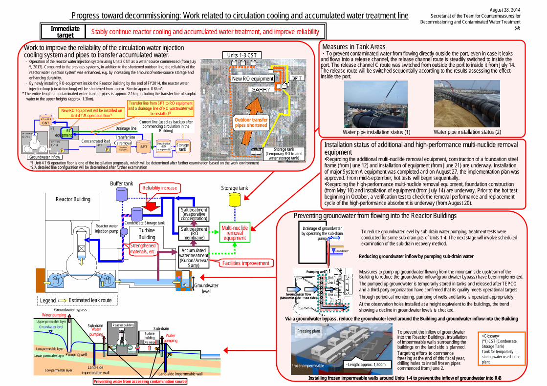
Upper permeable layer
Low-permeable layer
Water pumping
Water pumping Water
pumping
Pumping wellLower permeable layer
Low-permeable layer
Sub-drain Sub-drain
Drainage
Groundwater level Reactor building
Turbine building
Land-side impermeable wall Land-side impermeable wall
Groundwater bypass
Preventing water from accessing contamination source
Progress toward decommissioning: Work related to circulation cooling and accumulated water treatment line
Stably continue reactor cooling and accumulated water treatment, and improve reliabilityImmediate target
Facilities improvement
Reliability increase
Reactor Building
Turbine Building
Estimated leak routeLegend
地下水
Accumulated water treatment (Kurion/ Areva/
Sarry)
Strengthened materials, etc.
Multi-nuclide removal
equipment
Condensate Storage tank
Buffer tank
Reactor water injection pump
Groundwater level
Storage tank
Salt treatment(RO
membrane)
Salt treatment(evaporative
concentration)
August 28, 2014Secretariat of the Team for Countermeasures for
Decommissioning and Contaminated Water Treatment5/6
Reducing groundwater inflow by pumping sub-drain water
Via a groundwater bypass, reduce the groundwater level around the Building and groundwater inflow into the Building
Drainage of groundwaterby operating the sub-drain
pump
Groundwater
To reduce groundwater level by sub-drain water pumping, treatment tests were conducted for some sub-drain pits of Units 1-4. The next stage will involve scheduled examination of the sub-drain recovery method.
Measures to pump up groundwater flowing from the mountain side upstream of the Building to reduce the groundwater inflow (groundwater bypass) have been implemented.The pumped up groundwater is temporarily stored in tanks and released after TEPCO and a third-party organization have confirmed that its quality meets operational targets.Through periodical monitoring, pumping of wells and tanks is operated appropriately.At the observation holes installed at a height equivalent to the buildings, the trend showing a decline in groundwater levels is checked.
Preventing groundwater from flowing into the Reactor Buildings
<Glossary>(*1) CST (Condensate Storage Tank)Tank for temporarily storing water used in the plant.
Work to improve the reliability of the circulation water injection cooling system and pipes to transfer accumulated water. ・ Operation of the reactor water injection system using Unit 3 CST as a water source commenced (from July
5, 2013). Compared to the previous systems, in addition to the shortened outdoor line, the reliability of the reactor water injection system was enhanced, e.g. by increasing the amount of water-source storage and enhancing durability.
・ By newly installing RO equipment inside the Reactor Building by the end of FY2014, the reactor water injection loop (circulation loop) will be shortened from approx. 3km to approx. 0.8km*.
* The entire length of contaminated water transfer pipes is approx. 2.1km, including the transfer line of surplus water to the upper heights (approx. 1.3km).
※1 4号T/Bオペフロは設置案の1つであり、作業環境等を考慮し、今後更に検討を進めて決定予定
※2 詳細なライン構成等は、今後更に検討を進めて決定予定
#1~#3
R/B
#1~#4
T/B集中ラドHTI
SPT塩分除去(RO装置)
RO装置
P
#1~#3
CST 現状ライン(建屋内循環開始後はバックアップ)
Cs除去(SARRY、KURION)P
※1
地下水流入
移送ライン
排水ライン
RO装置を4号T/Bオペフロ※1に新設SPTからRO装置への移送ライン、
RO廃液の排水ライン設置※2
貯蔵タンク
※1 4号T/Bオペフロは設置案の1つであり、作業環境等を考慮し、今後更に検討を進めて決定予定
※2 詳細なライン構成等は、今後更に検討を進めて決定予定
#1~#3
R/B
#1~#4
T/B集中ラドHTI
SPT塩分除去(RO装置)
RO装置
P
#1~#3
CST 現状ライン(建屋内循環開始後はバックアップ)
Cs除去(SARRY、KURION)P
※1
地下水流入
移送ライン
排水ライン
RO装置を4号T/Bオペフロ※1に新設SPTからRO装置への移送ライン、
RO廃液の排水ライン設置※2
貯蔵タンク貯蔵タンク
New RO equipment will be installed on Unit 4 T/B operation floor*1
Transfer line from SPT to RO equipment and a drainage line of RO wastewater will
be installed*2
RO equipment
Groundwater inflow
Concentrated Rad
Drainage line
Transfer line Cs removal
Current line (used as backup after commencing circulation in the
Building)
Desalination (RO
equipment)Storage
tank
Units 1-3 CST
*1 Unit 4 T/B operation floor is one of the installation proposals, which will be determined after further examination based on the work environment*2 A detailed line configuration will be determined after further examination
New RO equipment
Storage tank (Temporary RO treated
water storage tank)
Outdoor transfer pipes shortened
Pumping well
Groundwater flow(Mountain side→sea side)
Unit 1 Unit 2
Unit 4
Installation status of additional and high-performance multi-nuclide removal equipment•Regarding the additional multi-nuclide removal equipment, construction of a foundation steel frame (from June 12) and installation of equipment (from June 21) are underway. Installation of major System A equipment was completed and on August 27, the implementation plan was approved. From mid-September, hot tests will begin sequentially.•Regarding the high-performance multi-nuclide removal equipment, foundation construction (from May 10) and installation of equipment (from July 14) are underway. Prior to the hot test beginning in October, a verification test to check the removal performance and replacement cycle of the high-performance absorbent is underway (from August 20).
Freezing plant
・Length: approx. 1,500mFrozen impermeable walls
To prevent the inflow of groundwater into the Reactor Buildings, installation of impermeable walls surrounding the buildings on the land side is planned.Targeting efforts to commence freezing at the end of this fiscal year, drilling holes to install frozen pipes commenced from June 2.
Installing frozen impermeable walls around Units 1-4 to prevent the inflow of groundwater into R/B
Measures in Tank Areas・To prevent contaminated water from flowing directly outside the port, even in case it leaks and flows into a release channel, the release channel route is steadily switched to inside the port. The release channel C route was switched from outside the port to inside it from July 14. The release route will be switched sequentially according to the results assessing the effect inside the port.
Water pipe installation status (1) Water pipe installation status (2)
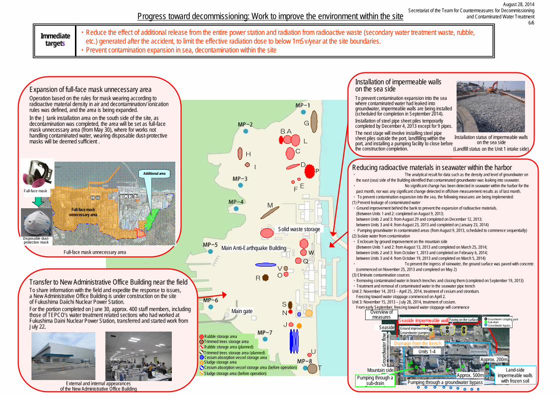
AB
F
固体廃棄物貯蔵庫
C
D
E
G
H
I
J
L
M
N
OR
T
S
U
Q
V
W
P
AB
F
固体廃棄物貯蔵庫
C
D
E
G
H
I
J
L
M
N
OR
T
S
U
Q
V
W
P
瓦礫保管エリア
伐採木保管エリア瓦礫保管エリア(予定地)伐採木保管エリア(予定地)セシウム吸着塔保管エリア
セシウム吸着塔保管エリア(運用前)スラッジ保管エリア
スラッジ保管エリア(運用前)
Progress toward decommissioning: Work to improve the environment within the site
・ Reduce the effect of additional release from the entire power station and radiation from radioactive waste (secondary water treatment waste, rubble, etc.) generated after the accident, to limit the effective radiation dose to below 1mSv/year at the site boundaries.
・ Prevent contamination expansion in sea, decontamination within the site
Immediatetargets
August 28, 2014Secretariat of the Team for Countermeasures for Decommissioning
and Contaminated Water Treatment6/6
Expansion of full-face mask unnecessary areaOperation based on the rules for mask wearing according to radioactive material density in air and decontamination/ ionization rules was defined, and the area is being expanded.In the J tank installation area on the south side of the site, as decontamination was completed, the area will be set as full-face mask unnecessary area (from May 30), where for works not handling contaminated water, wearing disposable dust-protective masks will be deemed sufficient .
Full-face mask unnecessary area
Additional area
Full-face mask unnecessary area
Disposable dust-protective mask
Full-face mask
Solid waste storage
Main Anti-Earthquake Building
Main gate
Rubble storage area Trimmed trees storage area
Trimmed trees storage area (planned)Rubble storage area (planned)
Sludge storage area
Sludge storage area (before operation)Cesium absorption vessel storage area (before operation)
Cesium absorption vessel storage area
Transfer to New Administrative Office Building near the fieldTo share information with the field and expedite the response to issues, a New Administrative Office Building is under construction on the site of Fukushima Daiichi Nuclear Power Station. For the portion completed on June 30, approx. 400 staff members, including those of TEPCO’s water treatment related sections who had worked at Fukushima Daini Nuclear Power Station, transferred and started work from July 22.
External and internal appearances of the New Administrative Office Building
Installation of impermeable wallson the sea sideTo prevent contamination expansion into the sea where contaminated water had leaked into groundwater, impermeable walls are being installed (scheduled for completion in September 2014).Installation of steel pipe sheet piles temporarily completed by December 4, 2013 except for 9 pipes.The next stage will involve installing steel pipe sheet piles outside the port, landfilling within the port, and installing a pumping facility to close before the construction completion.
Installation status of impermeable walls on the sea side
(Landfill status on the Unit 1 intake side)
Reducing radioactive materials in seawater within the harbor・ The analytical result for data such as the density and level of groundwater on
the east (sea) side of the Building identified that contaminated groundwater was leaking into seawater.・ No significant change has been detected in seawater within the harbor for the
past month, nor was any significant change detected in offshore measurement results as of last month.・ To prevent contamination expansion into the sea, the following measures are being implemented:(1) Prevent leakage of contaminated water・Ground improvement behind the bank to prevent the expansion of radioactive materials.
(Between Units 1 and 2: completed on August 9, 2013; between Units 2 and 3: from August 29 and completed on December 12, 2013; between Units 3 and 4: from August 23, 2013 and completed on January 23, 2014)
・ Pumping groundwater in contaminated areas (from August 9, 2013, scheduled to commence sequentially)(2) Isolate water from contamination・ Enclosure by ground improvement on the mountain side
(Between Units 1 and 2: from August 13, 2013 and completed on March 25, 2014;between Units 2 and 3: from October 1, 2013 and completed on February 6, 2014;between Units 3 and 4: from October 19, 2013 and completed on March 5, 2014)
・ To prevent the ingress of rainwater, the ground surface was paved with concrete (commenced on November 25, 2013 and completed on May 2)
(3) Eliminate contamination sources・Removing contaminated water in branch trenches and closing them (completed on September 19, 2013)・Treatment and removal of contaminated water in the seawater pipe trenchUnit 2: November 14, 2013 – April 25, 2014, treatment of cesium and strontium.
Freezing toward water stoppage commenced on April 2.Unit 3: November 15, 2013 – July 28, 2014, treatment of cesium.
From early September, freezing toward water stoppage will commence
海側遮水壁
地盤改良地下水くみ上げ
約200m
約500m
地下水採取点サブドレン地下水バイパス
海側遮水壁海側遮水壁
地盤改良地下水くみ上げ
約200m
約500m
地下水採取点サブドレン地下水バイパス
地下水採取点サブドレン地下水バイパス
地下水バイパスによるくみ上げ
1~4号機
トレンチからの排水
地表舗装等
山側
海側
地下水の流れ
対策の全体図
凍土方式による陸側遮水壁サブドレンによ
るくみ上げ
Overview of measures
Seaside Seaside impermeable wall Ground improvement Groundwater pumping
Paving on the surface Groundwater sampling point Sub-drain Groundwater bypass
Grou
ndwa
ter flo
w
Mountain side
Drainage from the trench Units 1-4
Approx. 200m
Approx. 500m Pumping through a sub-drain Pumping through a groundwater bypass
Land-side impermeable walls
with frozen soil