of ug programme be in “electronics and instrumentation engineering”
TRANSCRIPT
1
ENGINEERING MATHEMATICS – III
Sub Code : 10MAT31 IA Marks : 25
Hrs/ Week : 04 Exam Hours : 03
Total Hrs. : 52 Exam Marks : 100
PART – A
UNIT-1
Fourier series Convergence and divergence of infinite series of positive terms, definition
and illustrative examples*
Periodic functions, Dirichlet’s conditions, Fourier series of periodic functions
of period and arbitrary period, half range Fourier series. Complex form
of Fourier Series. Practical harmonic analysis.
7 Hours
UNIT-2
Fourier Transforms
Infinite Fourier transform, Fourier Sine and Cosine transforms, properties,
Inverse transforms
6 Hours
UNIT-3
Application of PDE Various possible solutions of one dimensional wave and heat equations, two
dimensional Laplace’s equation by the method of separation of variables,
Solution of all these equations with specified boundary conditions.
D’Alembert’s solution of one dimensional wave equation.
6 Hours
UNIT-4
Curve Fitting and Optimisation
Curve fitting by the method of least squares- Fitting of curves of the form
,y ax b 2 ,y a x b x c , y bx by a e ax
Optimization: Linear programming, mathematical formulation of linear
programming problem (LPP), Graphical method and simplex method.
7 Hours

2
PART-B
UNIT-5
Numerical Methods - 1 Numerical Solution of algebraic and transcendental equations: Regula-falsi
method, Newton - Raphson method. Iterative methods of solution of a system
of equations: Gauss-seidel and Relaxation methods. Largest eigen value and
the corresponding eigen vector by Rayleigh’s power method.
6 Hours
UNIT-6
Numerical Methods – 2
Finite differences: Forward and backward differences, Newton’s forward and
backward interpolation formulae. Divided differences - Newton’s divided
difference formula, Lagrange’s interpolation formula and inverse
interpolation formula.
Numerical integration: Simpson’s one-third, three-eighth and Weddle’s rules
(All formulae/rules without proof)
7 Hours
UNIT-7
Numerical Methods – 3 Numerical solutions of PDE – finite difference approximation to derivatives,
Numerical solution of two dimensional Laplace’s equation, one dimensional
heat and wave equations
7 Hours
UNIT-8
Difference Equations and Z-Transorms Difference equations: Basic definition; Z-transforms – definition, standard Z-
transforms, damping rule, shifting rule, initial value and final value theorems.
Inverse Z-transform. Application of Z-transforms to solve difference
equations.
6 Hours
Note: * In the case of illustrative examples, questions are not to be set.
TEXT BOOKS:
1. B.S. Grewal, Higher Engineering Mathematics, Latest edition,
Khanna Publishers.
2. Erwin Kreyszig, Advanced Engineering Mathematics, Latest
edition, Wiley Publications.
3
REFERENCE BOOKS: 1. B.V. Ramana, Higher Engineering Mathematics, Latest edition, Tata
Mc. Graw Hill Publications.
2. Peter V. O’Neil, Engineering Mathematics, CENGAGE Learning
India Pvt Ltd.Publishers.
ANALOG ELECTRONIC CIRCUITS
(Common to EC/TC/EE/IT/BM/ML/EI)
Sub Code : 10ES32 IA Marks : 25
Hrs/ Week : 04 Exam Hours : 03
Total Hrs. : 52 Exam Marks : 100
PART – A
UNIT 1:
Diode Circuits: Diode Resistance, Diode equivalent circuits, Transition and
diffusion capacitance, Reverse recovery time, Load line analysis, Rectifiers,
Clippers and clampers. 6 Hours
UNIT 2:
Transistor Biasing: Operating point, Fixed bias circuits, Emitter stabilized
biased circuits, Voltage divider biased, DC bias with voltage feedback,
Miscellaneous bias configurations, Design operations, Transistor switching
networks, PNP transistors, Bias stabilization. 6 Hours
UNIT 3:
Transistor at Low Frequencies: BJT transistor modeling, CE Fixed bias
configuration, Voltage divider bias, Emitter follower, CB configuration,
Collector feedback configuration, Analysis of circuits re model; analysis of
CE configuration using h- parameter model; Relationship between h-
parameter model of CE,CC and CE configuration. 7 Hours

4
UNIT 4:
Transistor Frequency Response: General frequency considerations, low
frequency response, Miller effect capacitance, High frequency response,
multistage frequency effects. 7 Hours
PART – B
UNIT 5:
(a) General Amplifiers: Cascade connections, Cascode connections,
Darlington connections. 3 Hours
(b) Feedback Amplifier: Feedback concept, Feedback connections type,
Practical feedback circuits. Design procedures for the feedback amplifiers.
4 Hours
UNIT 6:
Power Amplifiers: Definitions and amplifier types, series fed class A
amplifier, Transformer coupled Class A amplifiers, Class B amplifier
operations, Class B amplifier circuits, Amplifier distortions. Designing of
Power amplifiers. 7 Hours
UNIT 7:
Oscillators: Oscillator operation, Phase shift Oscillator, Wienbridge
Oscillator, Tuned Oscillator circuits, Crystal Oscillator. (BJT Version Only)
Simple design methods of Oscillators. 6 Hours
UNIT 8:
FET Amplifiers: FET small signal model, Biasing of FET, Common drain
common gate configurations, MOSFETs, FET amplifier networks.
6 Hours
TEXT BOOK:
1. “Electronic Devices and Circuit Theory”, Robert L. Boylestad
and Louis Nashelsky, PHI/Pearson Eduication. 9TH
Edition.

5
REFERENCE BOOKS:
1. „Integrated Electronics‟, Jacob Millman & Christos C. Halkias, Tata -
McGraw Hill, 2nd
Edition, 2010.
2. “Electronic Devices and Circuits”, David A. Bell, PHI, 4th
Edition,
2004.
3. “Analog Electronics Circuits: A Simplified Approach”, U.B.
Mahadevaswamy, Pearson/Saguine, 2007.
LOGIC DESIGN
(Common to EC/TC/EE/IT/BM/ML/EI)
Sub Code : 10ES33 IA Marks : 25
Hrs/ Week : 04 Exam Hours : 03
Total Hrs. : 52 Exam Marks : 100
UNIT 1:
Principles of combinational logic-1: Definition of combinational logic,
Canonical forms, Generation of switching equations from truth tables,
Karnaugh maps-3, 4 and 5 variables, Incompletely specified functions (Don’t
Care terms), Simplifying Max term equations. 6 Hours
UNIT 2:
Principles of combinational Logic-2: Quine-McCluskey minimization
technique- Quine-McCluskey using don’t care terms, Reduced Prime
Implicant Tables, Map entered variables. 7 Hours
UNIT 3:
Analysis and design of combinational logic - I: General approach,
Decoders-BCD decoders, Encoders. 6 Hours
UNIT 4:
Analysis and design of combinational logic - II: Digital multiplexers-
Using multiplexers as Boolean function generators. Adders and subtractors-
Cascading full adders, Look ahead carry, Binary comparators. Design
methods of building blocks of combinational logics.
7 Hours
6
PART – B
UNIT 5:
Sequential Circuits – 1: Basic Bistable Element, Latches, SR Latch,
Application of SR Latch, A Switch Debouncer, The S R
Latch, The gated
SR Latch, The gated D Latch, The Master-Slave Flip-Flops (Pulse-Triggered
Flip-Flops): The Master-Slave SR Flip-Flops, The Master-Slave JK Flip-
Flop, Edge Triggered Flip-Flop: The Positive Edge-Triggered D Flip-Flop,
Negative-Edge Triggered D Flip-Flop. 7 Hours
UNIT 6:
Sequential Circuits – 2: Characteristic Equations, Registers, Counters -
Binary Ripple Counters, Synchronous Binary counters, Counters based on
Shift Registers, Design of a Synchronous counters, Design of a Synchronous
Mod-6 Counter using clocked JK Flip-Flops Design of a Synchronous Mod-6
Counter using clocked D, T, or SR Flip-Flops 7 Hours
UNIT 7: Sequential Design - I: Introduction, Mealy and Moore Models, State
Machine Notation, Synchronous Sequential Circuit Analysis and Design.
6 Hours
UNIT 8:
Sequential Design - II: Construction of state Diagrams, Counter Design.
6 Hours
TEXT BOOKS:
1. “Digital Logic Applications and Design”, John M Yarbrough,
Thomson Learning, 2001.
2. “Digital Principles and Design “, Donald D Givone, Tata McGraw Hill
Edition, 2002.

7
REFERENCE BOOKS:
1. “Fundamentals of logic design”, Charles H Roth, Jr; Thomson
Learning, 2004.
2. “Logic and computer design Fundamentals”, Mono and Kim,
Pearson, Second edition, 2001.
3. “Logic Design”, Sudhakar Samuel, Pearson/Saguine, 2007
NETWORK ANALYSIS
(Common to EC/TC/EE/IT/BM/ML/EI)
Sub Code : 10ES34 IA Marks : 25
Hrs/ Week : 04 Exam Hours : 03
Total Hrs. : 52 Exam Marks : 100
PART – A
UNIT 1:
Basic Concepts: Practical sources, Source transformations, Network
reduction using Star – Delta transformation, Loop and node analysis With
linearly dependent and independent sources for DC and AC networks,
Concepts of super node and super mesh. 7 Hours
UNIT 2:
Network Topology: Graph of a network, Concept of tree and co-tree,
incidence matrix, tie-set, tie-set and cut-set schedules, Formulation of
equilibrium equations in matrix form, Solution of resistive networks,
Principle of duality. 7 Hours
UNIT 3:
Network Theorems – 1: Superposition, Reciprocity and Millman’s
theorems. 6 Hours
UNIT 4:
Network Theorems - II:
Thevinin’s and Norton’s theorems; Maximum Power transfer theorem
. 6 Hours

8
PART – B
UNIT 5: Resonant Circuits: Series and parallel resonance, frequency-
response of series and Parallel circuits, Q –factor, Bandwidth.
7 Hours
UNIT 6:
Transient behavior and initial conditions: Behavior of circuit elements
under switching condition and their Representation, evaluation of initial and
final conditions in RL, RC and RLC circuits for AC and DC excitations.
7 Hours
UNIT 7:
Laplace Transformation & Applications : Solution of networks, step,
ramp and impulse responses, waveform Synthesis. 6 Hours
UNIT 8:
Two port network parameters: Definition of z, y, h and transmission
parameters, modeling with these parameters, relationship between parameters
sets. 6 Hours
TEXT BOOKS: 1. “Network Analysis”, M. E. Van Valkenburg, PHI / Pearson Education,
3rd
Edition. Reprint 2002.
2. “Networks and systems”, Roy Choudhury, 2nd
edition, 2006 re-print,
New Age International Publications.
REFERENCE BOOKS:
1. “Engineering Circuit Analysis”, Hayt, Kemmerly and DurbinTMH 7th
Edition, 2010
2. “Basic Engineering Circuit Analysis”, J. David Irwin / R. Mark Nelms,
John Wiley, 8th
ed, 2006.
3. 3.“ Fundamentals of Electric Circuits”, Charles K Alexander and
Mathew N O Sadiku, Tata McGraw-Hill, 3 ed, 2009.

9
ELECTRONIC MEASUREMENTS
Sub Code : 10EI35 IA Marks : 25
Hrs/ Week : 04 Exam Hours : 03
Total Hrs. : 52 Exam Marks : 100
UNIT – 1:
Introduction
(a) Measurement System & Errors: Measurements, Significance of
measurements, methods of measurements, instruments and measurement
systems, Functions of instruments and measurement systems, Applications of
measurement systems. Gross errors and systematic errors, Absolute and
relative errors, Basic concepts of accuracy, Precision, Resolution and
Significant figures, Measurement error combinations.
(b) Multimeters: Introduction, DC voltmeter, DC ammeter, Multirange
voltmeter, Extending voltmeter ranges, Loading, AC voltmeter using
Rectifiers – Half wave and full wave, Peak responding and True RMS
voltmeters.
07 Hrs
UNIT – 2:
Digital Instruments
Digital Voltmeters – Introduction, DVM’s based on V–T, V–F and
Successive approximation principles, Resolution and sensitivity, General
specifications, Digital Multi-meters, Digital frequency meters, Digital
measurement of time.
06 Hrs
UNIT – 3:
Oscilloscopes
Introduction, Basic principles, CRT features, Block diagram and working of
each block, Typical CRT connections, Dual beam and dual trace CROs,
Electronic switch, measurement of frequency by Lissajous method, Sampling
and digital storage oscilloscopes.
07 Hrs
10
UNIT – 4:
Instrument Calibration
Introduction, comparison methods, digital multimeters as standard
instruments, calibration instruments, potentiometers, potentiometer
calibration methods.
06 Hrs
PART – B
UNIT – 5:
Signal Generators
Introduction, Fixed and variable AF oscillator, Standard signal generator,
Laboratory type signal generator, AF sine and Square wave generator,
Function generator, Square and Pulse generator, Sweep frequency generator,
Frequency synthesizer.
06 Hrs
UNIT – 6:
Bridge Circuits for Measurement of R, L & C:
Introduction, Wheatstone’s bridge, Kelvin Bridge; AC bridges, Capacitance
Comparison Bridge, inductance Comparison Bridge, Maxwell’s bridge, Hay
Bridge, Schearing Bridge, Wien Bridge, Wagner ground connection.
07 Hrs
UNIT – 7:
Opto Electronic Measurement
Optical spectrum, Luminosity curve, optical transducer, optical sources,
optical detectors: Photodiode, photo transistor, photo voltaic cells, thermal
sensors.
Signal Analyzer: Wave analyzer- frequency selective wave analyzer,
heterodyne wave analyzer, applications of wave analyzers. Harmonic
distortion analyzers.
Spectrum Analyzer: Basic Spectrum analyzer, spectral displays, spectra of
different signals.
07 Hrs
11
UNIT – 8:
Display Devices and Recorders: Introduction, electrical indicating
instruments, digital instruments, digital display methods, digital display unit.
Segmental Displays: Seven segmental display, dot matrices, LED, LCD,
decade counting assemblies, display systems.
Recorders: Recording requirements, analog recorders- Graphic recorders-
strip chart recorders & its types, X-Y recorder, Magnetic & Digital tape
recorders.
06 Hrs
Note: Wherever needed, numerical problems are to be solved in all units
TEXT BOOKS:
1. “Electronic Instrumentation”, H. S. Kalsi, TMH, 2004
2. “Electronic Instrumentation and Measurements”, David A Bell, PHI /
Pearson Education, 2006.
3. “Electrical and Electronic Measurements and Instrumentation”, A K
Sawhney, 9th
Edition, Dhanpat Rai & Sons, 2004.
REFERENCE BOOKS:
1. “Principles of measurement systems”, John P. Beately, 3rd
Edition,
Pearson Education, 2000
2. “Modern electronic instrumentation and measuring techniques”, Cooper
D & A D Helfrick, PHI, 1998.
TRANSDUCERS AND INSTRUMENTATION
Sub Code : 10EI36 IA MARKS : 25
Hrs/Week : 04 Exam Hours : 03
Total Hrs : 52 Exam Marks :100
PART-A
Unit-1:
Introduction: Measurements, Monitoring, Control & Analysis Instruments:
Transducer, Signal Conditioner & Transmitter, Display/Recording device.
Classification and Functional Elements of Instrument/measurement
system:

12
Mechanical, electrical and electronic instruments, Deflection and Null type
instruments, Analog and digital modes of operation, Elements of generalized
measurement system, Input-output configuration of measuring instruments
and measurement systems, methods of correction for interfering and
modifying inputs.
07 Hrs.
Unit-2:
Static and Dynamic Characteristics: Static calibration and error calibration
curve, Accuracy and Precision, indications of precision, Sensitivity, scale
range and scale span, Reproducibility and drift, static error, dead zone,
Linearity, Threshold, Resolution, Hysteresis, Dead zone and dead time,
signal to noise ratio, selection of transducers.
Dynamic response, Introduction to time domain and frequency domain
analysis
06 Hrs.
Unit-3:
Measurement of Displacement: Introduction, Principles of Transduction,
Variable resistance devices, variable Inductance Transducer, Induction
Potentiometers, Variable Capacitance Transducer, Hall Effect Devices,
Proximity Devices, Digital Transducer.
06 Hrs.
Unit-4:
Measurement of Strain: Introduction, Factors affecting strain
measurements, Types of Strain Gauges, Theory of operation of resistance
strain gauges, Types of Electrical Strain Gauges, Materials for Strain Gauges,
Gauging Techniques and other factors, Strain gauge Circuits, Temperature
Compensation, Application.
07 Hrs
PART-B
Unit-5:
Measurement of Temperature: Introduction, temperature scales,
mechanical temperature sensors, resistance-type temperature sensors,
resistance-type temperature sensors, platinum resistance thermometer,
thermistors, thermocouples, solid-state sensors, Quartz thermometer,
Temperature measurement by radiation methods, optical pyrometer,
calibration of thermometers.
07 Hrs.

13
Unit-6:
Measurement of Pressure: Introduction, Diaphragms, other elastic
elements, transduction methods, force balance transducer, solid-state devices,
thin-film pressure transducers, piezo-electric pressure transducer, pressure
multiplexer, pressure calibration.
06 Hrs.
Unit-7:
Measurement of Level:
Capacitance probes, conductivity probes, diaphragm level detector,
differential pressure level detector, float level devices, level gauges, optical
level switches, radiation level sensor, ultrasonic level detector, thermal level
sensors.
07 Hrs.
Unit-8:
Miscellaneous Sensors: Energy management Devices, Leak Detectors, Metal
Detectors, Noise Sensors, Speed Sensors, Thickness Measurement, Weather
Stations, pH sensors.
06 Hrs.
Note: Wherever needed, numerical problems are to be solved in all units
Text Books:
1. Electrical and Electronic Measurements and Instrumentation - A K
Sawhney, 9th
Edition, Dhanpat Rai & Sons, 2004.
2. Instrumentation Devices and Systems- C.S.Rangan, G.R.Sharma,
V.S.V.Mani, Tata McGraw Hill.
3. Process Measurement Instrument Engineers Handbook- Bela
G.Liptak, Chilton Book Company.
Reference Books: 1. Introduction to Instrumentation and Control-A.K.Ghosh, PHI.
2. Instrumentation Measurement and Analysis- B.C.Nakra,
K.K.Choudhry.
3. Measurement Systems Application and design- Ernest O.Doeblin-
Tata McGraw Hill.
14
ANALOG ELECTRONICS LAB
(Common to EC/TC/EE/IT/BM/ML/EI)
Sub Code : 10ESL37 IA Marks : 25
Hrs/ Week : 03 Exam Hours : 03
Total Hrs. : 42 Exam Marks : 50
NOTE: Use the Discrete components to test the circuits. LabView can be
used for the verification and testing along with the above.
1. Wiring of RC coupled Single stage FET & BJT amplifier and
determination of the gain-frequency response, input and output impedances.
2. Wiring of BJT Darlington Emitter follower with and without bootstrapping
and determination of the gain, input and output impedances (Single circuit)
(One Experiment)
3. Wiring of a two stage BJT Voltage series feed back amplifier and
determination of the gain, Frequency response, input and output impedances
with and without feedback (One Experiment)
4. Wiring and Testing for the performance of BJT-RC Phase shift Oscillator
for f0 ≤ 10 KHz
5. Testing for the performance of BJT – Hartley & Colpitts Oscillators for
RF range f0 ≥100KHz.
6. Testing for the performance of BJT -Crystal Oscillator for f0 > 100 KHz
7 Testing of Diode clipping (Single/Double ended) circuits for peak clipping,
peak detection
8. Testing of Clamping circuits: positive clamping /negative clamping.
9. Testing of a transformer less Class – B push pull power amplifier and
determination of its conversion efficiency.
10. Testing of Half wave, Full wave and Bridge Rectifier circuits with and
without Capacitor filter. Determination of ripple factor, regulation and
efficiency

15
11. Verification of Thevinin’s Theorem and Maximum Power Transfer
theorem for DC Circuits.
12. Characteristics of Series and Parallel resonant circuits.
LOGIC DESIGN LAB
(Common to EC/TC/EE/IT/BM/ML/EI)
Sub Code : 10ESL38 IA Marks : 25
Hrs/ Week : 03 Exam Hours : 03
Total Hrs. : 42 Exam Marks : 50
NOTE: Use discrete components to test and verify the logic gates. LabView
can be used for designing the gates along with the above.
1. Simplification, realization of Boolean expressions using logic
gates/Universal gates.
2. Realization of Half/Full adder and Half/Full Subtractors using logic
gates.
3. (i) Realization of parallel adder/Subtractors using 7483 chip
(ii) BCD to Excess-3 code conversion and vice versa.
4. Realization of Binary to Gray code conversion and vice versa
5. MUX/DEMUX – use of 74153, 74139 for arithmetic circuits and code
converter.
6. Realization of One/Two bit comparator and study of 7485 magnitude
comparator.
7. Use of a) Decoder chip to drive LED display and b) Priority encoder.
8. Truth table verification of Flip-Flops: (i) JK Master slave (ii) T type and
(iii) D type.
9. Realization of 3 bit counters as a sequential circuit and MOD – N
counter design (7476, 7490, 74192, 74193).
10. Shift left; Shift right, SIPO, SISO, PISO, PIPO operations using 74S95.
11. Wiring and testing Ring counter/Johnson counter.
12. Wiring and testing of Sequence generator.
16
IV SEMESTER
ENGINEERING MATHEMATICS - IV
Sub Code : 10MAT41 IA Marks : 25
Hrs/ Week : 04 Exam Hours : 03
Total Hrs. : 52 Exam Marks : 100
PART – A
Unit-1:
NUMERICAL METHODS - 1
Numerical solution of ordinary differential equations of first order and first
degree; Picard’s method, Taylor’s series method, modified Euler’s method,
Runge-kutta method of fourth-order. Milne’s and Adams - Bashforth
predictor and corrector methods (No derivations of formulae).
[6 hours]
Unit-2:
NUMERICAL METHODS – 2
Numerical solution of simultaneous first order ordinary differential
equations: Picard’s method, Runge-Kutta method of fourth-order. Numerical
solution of second order ordinary differential quations: Picard’s method,
Runge-Kutta method and Milne’s method.
[6 hours]
Unit-3:
Complex Variables – 1
Function of a complex variable, Analytic functions-Cauchy-Riemann
equations in cartesian and polar forms. Properties of analytic functions.
Application to flow problems- complex potential, velocity potential,
equipotential lines, stream functions, stream lines.
[7 hours]
Unit-4: Complex Variables – 2
Conformal Transformations: Bilinear Transformations. Discussion of
Transformations:
w = z2, w = ez , w = z + (a2 / z) . Complex line integrals- Cauchy’s theorem
and Cauchy’s integral formula.
[7 hours]

17
PART-B
Unit-5:
SPECIAL FUNCTIONS
Solution of Laplace equation in cylindrical and spherical systems leading
Bessel’s and Legendre’s differential equations, Series solution of Bessel’s
differential equation leading to
Bessel function of first kind. Orthogonal property of Bessel functions. Series
solution of Legendre’s differential equation leading to Legendre polynomials,
Rodrigue’s formula.
[7 hours]
Unit-6:
PROBABILITY THEORY - 1
Probability of an event, empherical and axiomatic definition, probability
associated with set theory, addition law, conditional probability,
multiplication law, Baye’s theorem.
[6 hours]
Unit-7:
PROBABILITY THEORY- 2
Random variables (discrete and continuous), probability density function,
cumulative density function. Probability distributions – Binomial and Poisson
distributions; Exponential and normal distributions.
[7 hours]
Unit-8:
SAMPLING THEORY
Sampling, Sampling distributions, standard error, test of hypothesis for
means, confidence limits for means, student’s t distribution. Chi -Square
distribution as a test of goodness of fit.
[6 hours]
Text Books:
1. B.S. Grewal, Higher Engineering Mathematics, Latest edition, Khanna
Publishers
2. Erwin Kreyszig, Advanced Engineering Mathematics, Latest edition,
Wiley Publications.
Reference Book:
1. B.V. Ramana, Higher Engineering Mathematics, Latest edition, Tata Mc.
Graw Hill Publications.

18
2. Peter V. O’Neil, Engineering Mathematics, CENGAGE Learning India Pvt
Ltd.Publishers
MICROCONTROLLERS
(Common to EC/TC/EE/IT/BM/ML/EI)
Sub Code : 10ES42 IA Marks : 25
Hrs/ Week : 04 Exam Hours : 03
Total Hrs. : 52 Exam Marks : 100
PART – A
UNIT 1:
Microprocessors and microcontroller. Introduction, Microprocessors and
Microcontrollers, RISC & CISC CPU Architectures, Harvard & Von-
Neumann CPU architecture, Computer software.
The 8051 Architecture: Introduction, Architecture of 8051, Pin diagram of
8051, Memory organization, External Memory interfacing, Stacks.
6 Hours
UNIT 2:
Addressing Modes: Introduction, Instruction syntax, Data types, Subroutines,
Addressing modes: Immediate addressing , Register addressing, Direct
addressing, Indirect addressing, relative addressing, Absolute addressing,
Long addressing, Indexed addressing, Bit inherent addressing, bit direct
addressing.
Instruction set: Instruction timings, 8051 instructions: Data transfer
instructions, Arithmetic instructions, Logical instructions, Branch
instructions, Subroutine instructions, Bit manipulation instruction.
6 Hours
UNIT 3:
8051 programming: Assembler directives, Assembly language programs and
Time delay calculations. 6 Hours
UNIT 4:
8051 Interfacing and Applications: Basics of I/O concepts, I/O Port
Operation, Interfacing 8051 to LCD, Keyboard, parallel and serial ADC,
DAC, Stepper motor interfacing and DC motor interfacing and programming
7 Hours

19
PART – B
UNIT 5:
8051 Interrupts and Timers/counters: Basics of interrupts, 8051 interrupt
structure, Timers and Counters, 8051 timers/counters, programming 8051
timers in assembly and C . 6 Hours
UNIT 6:
8051 Serial Communication: Data communication, Basics of Serial Data
Communication, 8051 Serial Communication, connections to RS-232, Serial
communication Programming in assembly and C.
8255A Programmable Peripheral Interface:, Architecture of 8255A, I/O
addressing,, I/O devices interfacing with 8051 using 8255A.
5 Hours
Course Aim – The MSP430 microcontroller is ideally suited for development
of low-power embedded systems that must run on batteries for many years.
There are also applications where MSP430 microcontroller must operate on
energy harvested from the environment. This is possible due to the ultra-low
power operation of MSP430 and the fact that it provides a complete system
solution including a RISC CPU, flash memory, on-chip data converters and
on-chip peripherals.
UNIT 7:
Motivation for MSP430microcontrollers – Low Power embedded systems,
On-chip peripherals (analog and digital), low-power RF capabilities. Target
applications (Single-chip, low cost, low power, high performance system
design).
2 Hours
MSP430 RISC CPU architecture, Compiler-friendly features, Instruction
set, Clock system, Memory subsystem. Key differentiating factors between
different MSP430 families.
2 Hours Introduction to Code Composer Studio (CCS v4). Understanding how to
use CCS for Assembly, C, Assembly+C projects for MSP430
microcontrollers. Interrupt programming.
2 Hours

20
Digital I/O – I/O ports programming using C and assembly, Understanding
the muxing scheme of the MSP430 pins. 2 Hours
UNIT 8:
On-chip peripherals. Watchdog Timer, Comparator, Op-Amp, Basic
Timer, Real Time Clock (RTC), ADC, DAC, SD16, LCD, DMA.
2 Hours Using the Low-power features of MSP430. Clock system, low-power
modes, Clock request feature, Low-power programming and Interrupt.
2 Hours
Interfacing LED, LCD, External memory. Seven segment LED modules
interfacing. Example – Real-time clock.
2 Hours Case Studies of applications of MSP430 - Data acquisition system, Wired
Sensor network, Wireless sensor network with Chipcon RF interfaces.
2 Hours
TEXT BOOKS:
1. “The 8051 Microcontroller and Embedded Systems – using assembly
and C ”-, Muhammad Ali Mazidi and Janice Gillespie Mazidi and
Rollin D. McKinlay; PHI, 2006 / Pearson, 2006
2. “MSP430 Microcontroller Basics”, John Davies, Elsevier, 2010
(Indian edition available)
REFERENCE BOOKS:
1. “The 8051 Microcontroller Architecture, Programming &
Applications”, 2e Kenneth J. Ayala ;, Penram International, 1996 /
Thomson Learning 2005.
2. “The 8051 Microcontroller”, V.Udayashankar and
MalikarjunaSwamy, TMH, 2009
3. MSP430 Teaching CD-ROM, Texas Instruments, 2008 (can be
requested http://www.uniti.in )
4. Microcontrollers: Architecture, Programming, Interfacing and
System Design”,Raj Kamal, “Pearson Education, 2005

21
CONTROL SYSTEMS
(Common to EC/TC/EE/IT/BM/ML/EI)
Sub Code : 10ES43 IA Marks : 25
Hrs/ Week : 04 Exam Hours : 03
Total Hrs. : 52 Exam Marks : 100
PART – A
UNIT 1:
Modeling of Systems: Introduction to Control Systems, Types of Control
Systems, Effect of Feedback Systems, Differential equation of Physical
Systems -Mechanical systems, Friction, Translational systems (Mechanical
accelerometer, systems excluded), Rotational systems, Gear trains, Electrical
systems, Analogous systems. 7 Hours
UNIT 2:
Block diagrams and signal flow graphs: Transfer functions, Block diagram
algebra, Signal Flow graphs (State variable formulation excluded) 6 Hours
UNIT 3:
Time Response of feed back control systems: Standard test signals, Unit
step response of First and second order systems, Time response
specifications, Time response specifications of second order systems, steady
– state errors and error constants. Introduction to PID Controllers(excluding
design) 7 Hours
UNIT 4: Stability analysis: Concepts of stability, Necessary conditions for Stability,
Routh- stability criterion, Relative stability analysis; More on the Routh
stability criterion. 6 Hours
PART – B
UNIT 5:
Root–Locus Techniques: Introduction, The root locus concepts,
Construction of root loci. 6 Hours
22
UNIT 6:
Frequency domain analysis: Correlation between time and frequency
response, Bode plots, Experimental determination of transfer functions,
Assessment of relative stability using Bode Plots. Introduction to lead, lag
and lead-lag compensating networks (excluding design). 7 Hours
UNIT 7:
Stability in the frequency domain: Introduction to Polar Plots, (Inverse
Polar Plots excluded) Mathematical preliminaries, Nyquist Stability criterion,
Assessment of relative stability using Nyquist criterion, (Systems with
transportation lag excluded). 7 Hours
UNIT 8:
Introduction to State variable analysis: Concepts of state, state variable
and state models for electrical systems, Solution of state equations.
6 Hours
TEXT BOOK :
1. J. Nagarath and M.Gopal, “Control Systems Engineering”, New Age
International (P) Limited, Publishers, Fourth edition – 2005.
REFERENCE BOOKS:
3. “Modern Control Engineering “, K. Ogata, Pearson Education Asia/
PHI, 4th
Edition, 2002.
4. “Automatic Control Systems”, Benjamin C. Kuo, John Wiley India
Pvt. Ltd., 8th
Edition, 2008.
5. “Feedback and Control System”, Joseph J Distefano III et al.,
Schaum’s Outlines, TMH, 2nd
Edition 2007.
23
SIGNALS & SYSTEMS
(Common to EC/TC/IT/BM/ML/EI)
Sub Code : 10EC44 IA Marks : 25
Hrs/ Week : 04 Exam Hours : 03
Total Hrs. : 52 Exam Marks : 100
PART – A
UNIT 1:
Introduction: Definitions of a signal and a system, classification of signals,
basic Operations on signals, elementary signals, Systems viewed as
Interconnections of operations, properties of systems. 6 Hours
UNIT 2:
Time-domain representations for LTI systems – 1: Convolution, impulse
response representation, Convolution Sum and Convolution Integral.
6 Hours
UNIT 3:
Time-domain representations for LTI systems – 2: Properties of impulse
response representation, Differential and difference equation Representations,
Block diagram representations. 7 Hours
UNIT 4:
Fourier representation for signals – 1: Introduction, Discrete time and
continuous time Fourier series (derivation of series excluded) and their
properties . 7 Hours
PART – B
UNIT 5:
Fourier representation for signals – 2: Discrete and continuous Fourier
transforms(derivations of transforms are excluded) and their properties.
6 Hours
24
UNIT 6:
Applications of Fourier representations: Introduction, Frequency response
of LTI systems, Fourier transform representation of periodic signals, Fourier
transform representation of discrete time signals. Sampling theorm and
Nyquist rate. 7 Hours
UNIT 7:
Z-Transforms – 1: Introduction, Z – transform, properties of ROC,
properties of Z – transforms, inversion of Z – transforms.
6 Hours
UNIT 8:
Z-transforms – 2: Transform analysis of LTI Systems, unilateral Z-
Transform and its application to solve difference equations. 7 Hours
TEXT BOOK
1. Simon Haykin, “Signals and Systems”, John Wiley India Pvt. Ltd., 2nd
Edn, 2008.
2. Michael Roberts, “Fundamentals of Signals & Systems”, 2nd
ed, Tata
McGraw-Hill, 2010.
REFERENCE BOOKS:
Alan V Oppenheim, Alan S, Willsky and A Hamid Nawab, “Signals
and Systems” Pearson Education Asia / PHI, 2nd
edition, 1997. Indian
Reprint 2002.
H. P Hsu, R. Ranjan, “Signals and Systems”, Scham’s outlines, TMH,
2006.
B. P. Lathi, “Linear Systems and Signals”, Oxford University Press,
2005.
Ganesh Rao and Satish Tunga, “Signals and Systems”,
Pearson/Sanguine Technical Publishers, 2004.

25
FUNDAMENTALS OF HDL
(Common to EC/TC/IT/BM/ML/EI)
Sub Code : 10EC45 IA Marks : 25
Hrs/ Week : 04 Exam Hours : 03
Total Hrs. : 52 Exam Marks : 100
PART – A
UNIT 1:
Introduction: Why HDL? , A Brief History of HDL, Structure of HDL
Module, Operators, Data types, Types of Descriptions, simulation and
synthesis, Brief comparison of VHDL and Verilog
7 Hours
UNIT 2:
Data –Flow Descriptions: Highlights of Data-Flow Descriptions, Structure
of Data-Flow Description, Data Type – Vectors. 6 Hours
UNIT 3:
Behavioral Descriptions: Behavioral Description highlights, structure of
HDL behavioral Description, The VHDL variable –Assignment Statement,
sequential statements. 6 Hours
UNIT 4:
Structural Descriptions: Highlights of structural Description, Organization
of the structural Descriptions, Binding, state Machines, Generate, Generic,
and Parameter statements.
7 Hours
PART – B
UNIT 5:
Procedures, Tasks, and Functions: Highlights of Procedures, tasks, and
Functions, Procedures and tasks, Functions.
Advanced HDL Descriptions: File Processing, Examples of File Processing
7 Hours

26
UNIT 6:
Mixed –Type Descriptions: Why Mixed-Type Description? VHDL User-
Defined Types, VHDL Packages, Mixed-Type Description examples
6 Hours
UNIT 7:
Mixed –Language Descriptions: Highlights of Mixed-Language
Description, How to invoke One language from the Other, Mixed-language
Description Examples, Limitations of Mixed-Language Description.
7 Hours
UNIT 8:
Synthesis Basics: Highlights of Synthesis, Synthesis information from Entity
and Module, Mapping Process and Always in the Hardware Domain.
6 Hours
TEXT BOOKS:
1. HDL Programming (VHDL and Verilog)- Nazeih M.Botros- John
Weily India Pvt. Ltd. 2008.
REFERENCE BOOKS:
1. Fundamentals of HDL – Cyril P.R. Pearson/Sanguin 2010.
2. VHDL -Douglas perry-Tata McGraw-Hill.
3. A Verilog HDL Primer- J.Bhaskar – BS Publications
4. Circuit Design with VHDL-Volnei A.Pedroni-PHI.
LINEAR IC‟s & APPLICATIONS
(Common to EC/TC/IT/BM/ML/EI)
Sub Code : 10EC46 IA Marks : 25
Hrs/ Week : 04 Exam Hours : 03
Total Hrs. : 52 Exam Marks : 100
PART – A
UNIT 1:
Operational Amplifier Fundamentals: Basic Op-Amp circuit, Op-Amp
parameters – Input and output voltage, CMRR and PSRR, offset voltages and
currents, Input and output impedances, Slew rate and Frequency limitations;
Op-Amps as DC Amplifiers- Biasing Op-Amps, Direct coupled -Voltage

27
Followers, Non-inverting Amplifiers, Inverting amplifiers, Summing
amplifiers, Difference amplifier. 7 Hours
UNIT 2:
Op-Amps as AC Amplifiers: Capacitor coupled Voltage Follower, High
input impedance - Capacitor coupled Voltage Follower, Capacitor coupled
Non-inverting Amplifiers, High input impedance - Capacitor coupled Non-
inverting Amplifiers, Capacitor coupled Inverting amplifiers, setting the
upper cut-off frequency, Capacitor coupled Difference amplifier, Use of a
single polarity power supply. 7 Hours
UNIT 3:
Op-Amps frequency response and compensation: Circuit stability,
Frequency and phase response, Frequency compensating methods, Band
width, Slew rate effects, Zin Mod compensation, and circuit stability
precautions. 6 Hours
UNIT 4:
OP-AMP Applications: Voltage sources, current sources and current sinks,
Current amplifiers, instrumentation amplifier, precision rectifiers, Limiting
circuits. 6 Hours
PART – B
UNIT 5:
More applications: Clamping circuits, Peak detectors, sample and hold
circuits, V to I and I to V converters, Log and antilog amplifiers, Multiplier
and divider, Triangular / rectangular wave generators, Wave form generator
design, phase shift oscillator, Wein bridge oscillator.
7 Hours
UNIT 6:
Non-linear circuit applications: crossing detectors, inverting Schmitt
trigger circuits, Monostable & Astable multivibrator, Active Filters –First and
second order Low pass & High pass filters. 6 Hours
28
UNIT 7:
Voltage Regulators: Introduction, Series Op-Amp regulator, IC Voltage
regulators, 723 general purpose regulator, Switching regulator.
6 Hours
UNIT 8:
Other Linear IC applications: 555 timer - Basic timer circuit, 555 timer used
as astable and monostable multivibrator, Schmitt trigger; PLL-operating
principles, Phase detector / comparator, VCO; D/A and A/ D converters –
Basic DAC Techniques, AD converters. 7 Hours
TEXT BOOKS:
1. “Operational Amplifiers and Linear IC‟s”, David A. Bell, 2nd
edition,
PHI/Pearson, 2004.
2. “Linear Integrated Circuits”, D. Roy Choudhury and Shail B. Jain, 2nd
edition, Reprint 2006, New Age International.
REFERENCE BOOKS:
1. “Opamps- Design, Applications and Trouble Shooting”, Terrell,
Elsevier, 3rd
ed. 2006.
2. “Operational Amplifiers”, George Clayton and Steve Winder, Elsever
3. 5th
ed., 2008.
4. “Operational Amplifiers and Linear Integrated Circuits”, Robert. F.
Coughlin & Fred.F. Driscoll, PHI/Pearson, 2006.
5. “Design with Operational Amplifiers and Analog Integrated
Circuits”, Sergio Franco, TMH, 3e, 2005.
29
MICROCONTROLLERS LAB
(Common to EC/TC/EE/IT/BM/ML/EI)
Sub Code : 10ESL47 IA Marks : 25
Hrs/ Week : 03 Exam Hours : 03
Total Hrs. : 42 Exam Marks : 50
I. PROGRAMMING
1. Data Transfer - Block move, Exchange, Sorting, Finding largest element in
an array.
2. Arithmetic Instructions - Addition/subtraction, multiplication and division,
square, Cube – (16 bits Arithmetic operations – bit addressable).
3. Counters.
4. Boolean & Logical Instructions (Bit manipulations).
5. Conditional CALL & RETURN.
6. Code conversion: BCD – ASCII; ASCII – Decimal; Decimal - ASCII;
HEX - Decimal and Decimal - HEX .
7. Programs to generate delay, Programs using serial port and on-Chip timer /
counter.
Note: Programming exercise is to be done on both 8051 & MSP430.
II. INTERFACING:
Write C programs to interface 8051 chip to Interfacing modules to develop
single chip solutions.
8. Simple Calculator using 6 digit seven segment displays and Hex Keyboard
interface to 8051.
9. Alphanumeric LCD panel and Hex keypad input interface to 8051.
10. External ADC and Temperature control interface to 8051.
11. Generate different waveforms Sine, Square, Triangular, Ramp etc. using
DAC interface to 8051; change the frequency and amplitude.
12. Stepper and DC motor control interface to 8051.
13. Elevator interface to 8051.

30
HDL LAB
(Common to EC/TC/IT/BM/ML/EI)
Sub Code : 10ECL48 IA Marks : 25
Hrs/ Week : 03 Exam Hours : 03
Total Hrs. : 42 Exam Marks : 50
Note: Programming can be done using any compiler. Download the
programs on a FPGA/CPLD boards such as
Apex/Acex/Max/Spartan/Sinfi/TK Base or equivalent and performance
testing may be done using 32 channel pattern generator and logic analyzer
apart from verification by simulation with tools such as Altera/Modelsim or
equivalent.
PROGRAMMING (using VHDL /Verilog)
1. Write HDL code to realize all the logic gates
2. Write a HDL program for the following combinational designs
1. 2 to 4 decoder
2. 8 to 3 (encoder without priority & with priority)
3. 8 to 1 multiplexer
4. 4 bit binary to gray converter
5. Multiplexer, de-multiplexer, comparator.
6. Write a HDL code to describe the functions of a Full Adder Using three
modeling styles.
7. Write a model for 32 bit ALU using the schematic diagram shown below
A (31:0) B (31:0)
Out
1. ALU should use combinational logic to calculate an output based on the
four bit op-code input.
Opcode (3:0)
Enable
31
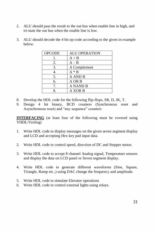
2. ALU should pass the result to the out bus when enable line in high, and
tri-state the out bus when the enable line is low.
3. ALU should decode the 4 bit op-code according to the given in example
below.
OPCODE ALU OPERATION
1. A + B
2. A – B
3. A Complement
4. A * B
5. A AND B
6. A OR B
7. A NAND B
8. A XOR B
8. Develop the HDL code for the following flip-flops, SR, D, JK, T.
9. Design 4 bit binary, BCD counters (Synchronous reset and
Asynchronous reset) and “any sequence” counters
INTERFACING (at least four of the following must be covered using
VHDL/Verilog)
1. Write HDL code to display messages on the given seven segment display
and LCD and accepting Hex key pad input data.
2. Write HDL code to control speed, direction of DC and Stepper motor.
3. Write HDL code to accept 8 channel Analog signal, Temperature sensors
and display the data on LCD panel or Seven segment display.
4. Write HDL code to generate different waveforms (Sine, Square,
Triangle, Ramp etc.,) using DAC change the frequency and amplitude.
5. Write HDL code to simulate Elevator operations
6. Write HDL code to control external lights using relays.